JP5688357B2 - Building management apparatus, building management system, and building management program - Google Patents
Building management apparatus, building management system, and building management program Download PDFInfo
- Publication number
- JP5688357B2 JP5688357B2 JP2011244546A JP2011244546A JP5688357B2 JP 5688357 B2 JP5688357 B2 JP 5688357B2 JP 2011244546 A JP2011244546 A JP 2011244546A JP 2011244546 A JP2011244546 A JP 2011244546A JP 5688357 B2 JP5688357 B2 JP 5688357B2
- Authority
- JP
- Japan
- Prior art keywords
- request
- equipment
- response
- facility
- building management
- Prior art date
- Legal status (The legal status is an assumption and is not a legal conclusion. Google has not performed a legal analysis and makes no representation as to the accuracy of the status listed.)
- Active
Links
- 230000004044 response Effects 0.000 claims description 164
- 230000005540 biological transmission Effects 0.000 description 38
- 230000000875 corresponding effect Effects 0.000 description 37
- 238000012986 modification Methods 0.000 description 25
- 230000004048 modification Effects 0.000 description 25
- 238000012423 maintenance Methods 0.000 description 17
- 238000004891 communication Methods 0.000 description 16
- 238000000034 method Methods 0.000 description 11
- 238000012544 monitoring process Methods 0.000 description 9
- 230000006870 function Effects 0.000 description 7
- 238000010586 diagram Methods 0.000 description 5
- 238000009434 installation Methods 0.000 description 5
- 238000012545 processing Methods 0.000 description 5
- 238000005516 engineering process Methods 0.000 description 2
- 239000000284 extract Substances 0.000 description 2
- 230000002596 correlated effect Effects 0.000 description 1
- 230000000694 effects Effects 0.000 description 1
- 230000010365 information processing Effects 0.000 description 1
- 238000007639 printing Methods 0.000 description 1
- 238000013404 process transfer Methods 0.000 description 1
Images


Description
本発明は、ビル内に設置されている設備機器を管理するビル管理装置、ビル管理システム及びビル管理プログラムに関する。 The present invention relates to a building management apparatus, a building management system, and a building management program for managing equipment installed in a building.
ビル管理サービスは、顧客のビルに電力量計や監視カメラ等の様々な設備機器を設置し、電力消費レポートや監視カメラの映像等を顧客に提供するサービスである。顧客のビルに設置された設備機器には、IPアドレス(Internet Protocol Address)が割り当てられてネットワークへの接続が可能な設備機器がある。このような設備機器の設置や保守を行う場合、各設備機器にネットワーク経由で保守端末を接続し、保守端末から各種の設定を行う。このようにネットワーク経由で設備機器の設定を行う場合、各設備機器に割り当てられているIPアドレスを、保守等を行う作業員が把握している必要がある。従来の運用では、設備機器を設置するときに、設備機器とIPアドレスとの対応付けを示す機器管理台帳を作成することで、各設備機器のIPアドレスを管理していた。しかしながら、機器管理台帳の作成時の記入ミスや、設備機器を新たに追加したときの機器管理台帳への反映漏れ等によって、実際に設置されている設備機器と機器管理台帳に記載されている内容とが一致しない場合がある。この場合、実際に設置されている設備機器を作業員が手作業で調査する必要があるため、保守作業に時間がかかってしまうことがある。従って、ネットワークに実際に接続されている設備機器の種別と、各設備機器に割り当てられているIPアドレスとを自動的に識別して対応付けを行い、機器管理台帳に記載されている内容と、ネットワークの実際の構成との差異を容易に確認できることが望ましい。 The building management service is a service in which various equipment such as a watt hour meter and a monitoring camera are installed in a customer's building, and a power consumption report and a video of the monitoring camera are provided to the customer. Among equipment installed in a customer's building, there is equipment that can be connected to a network by being assigned an IP address (Internet Protocol Address). When performing installation and maintenance of such equipment, a maintenance terminal is connected to each equipment via a network, and various settings are performed from the maintenance terminal. Thus, when setting an equipment device via a network, it is necessary for an operator who performs maintenance or the like to know the IP address assigned to each equipment device. In the conventional operation, when installing the equipment, the IP address of each equipment is managed by creating a device management ledger indicating the correspondence between the equipment and the IP address. However, due to mistakes in the creation of the device management ledger, the contents of the equipment installed in the device management ledger and the contents that are actually installed due to omissions in the device management ledger when new equipment is added. May not match. In this case, since it is necessary for a worker to manually investigate the installed equipment, maintenance work may take time. Therefore, the type of equipment actually connected to the network and the IP address assigned to each equipment are automatically identified and correlated, and the contents described in the equipment management ledger It is desirable to be able to easily confirm the difference from the actual configuration of the network.
下記の特許文献1には、ネットワークに接続されているネットワークデバイスにWebサーバを同梱し、SNMP(Simple Network Management Protocol)、LDAP(Lightweight Directory Access Protocol)、Novell社のNDS(NetWare Directory Service)又はSLP(Service Location Protocol)を利用して、ネットワークデバイスのIPアドレス、名称及び製品名を取得する方法が開示されている。
In the following
また、下記の特許文献2には、家庭内に存在するデジタルカメラ、スキャナ及びプリンタ等の装置のように本来はIPアドレスが割り当てられていない制御対象製品にIPアドレスを割り当て、インターネットを経由して受信したデータからIPアドレスを識別し、識別されたIPアドレスに対応する制御対象製品にデータを出力するゲートウェイ装置が開示されている。このゲートウェイ装置は、制御対象製品と当該制御対象製品に割り当てられているIPアドレスとの対応関係を示すIPアドレス管理テーブルを備えている。
Further, in
また、下記の特許文献3には、機器のMACアドレスに基づいて当該機器に関する情報を取得するためのデータベースを予め構築しておき、ネットワークに接続されている機器からMACアドレスを取得し、そのデータベースを参照することで、予め登録されている機器を認識する方法が開示されている。未登録の機器を登録する場合、管理者が機器を選択して登録を指示する。
In
また、下記の特許文献4には、ネットワークに接続されているネットワーク接続機器の情報を、NetBIOSを用いて収集する装置が開示されている。 Patent Document 4 below discloses an apparatus that collects information of network connection devices connected to a network using NetBIOS.
また、下記の特許文献5には、予め識別されている機器からポーリングによって情報を収集する装置が開示されている。
しかしながら、上述した従来技術では、ネットワークに接続されている設備機器の種別と、各設備機器に割り当てられているIPアドレスとを自動的に識別して対応付けることは困難である。 However, with the above-described conventional technology, it is difficult to automatically identify and associate the type of equipment connected to the network and the IP address assigned to each equipment.
例えば特許文献1に記載された方法では、どのような通信プロトコルを用いたとしても、ネットワークデバイスからIPアドレスや名称等の情報を取得するためには、そのネットワークデバイスが当該通信プロトコルに対応している必要がある。SNMP等のプロトコルに対応していないネットワークデバイスからはIPアドレスや名称等の情報を取得することができない。そのため、ネットワークデバイスがSNMP等のプロトコルに対応していない場合、そのネットワークデバイスの種別とIPアドレスとを自動的に識別して対応付けることは困難である。
For example, in the method described in
また、特許文献2に記載のゲートウェイ装置は、制御対象製品と当該制御対象製品に割り当てられているIPアドレスとの対応付けを示すIPアドレス管理テーブルを備えているに過ぎない。そのIPアドレス管理テーブルは予め作成されており、特許文献2に記載のゲートウェイ装置では、ネットワークに接続されている制御対象製品の種別と、その制御対象製品のIPアドレスとを自動的に識別して対応付けることは困難である。
In addition, the gateway device described in
また、特許文献3に記載された方法は、予め登録されている機器をMACアドレスとデータベースとに基づいて認識するに過ぎず、ネットワークに接続されている機器の種別と、その機器のIPアドレスとを自動的に識別して対応付けることは困難である。
In addition, the method described in
また、特許文献4に記載された装置は、NetBIOSという通信インターフェースを用いているため、汎用の機器に適用して汎用の機器の種別と当該機器のIPアドレスとを自動的に識別して対応付けることは困難である。 In addition, since the device described in Patent Document 4 uses a communication interface called NetBIOS, it is applied to a general-purpose device and automatically identifies and associates the type of general-purpose device and the IP address of the device. It is difficult.
また、特許文献5に記載された装置は、予め識別されている装置を対象としており、ネットワークに接続されている機器の種別と、その機器のIPアドレスとを自動的に識別して対応付けることは困難である。
The device described in
以上のように、従来技術では、ネットワークに接続されている設備機器の種別と、各設備機器に割り当てられているIPアドレスとを自動的に識別して対応付けることは困難であり、機器管理台帳に記載されている内容と、ネットワークの実際の構成との差異を確認することは容易ではない。 As described above, according to the conventional technology, it is difficult to automatically identify and associate the type of equipment connected to the network and the IP address assigned to each equipment. It is not easy to confirm the difference between the contents described and the actual configuration of the network.
本発明の目的は、ネットワークに接続されている設備機器の種別と、各設備機器に割り当てられているアドレスとを識別することが可能なビル管理装置、ビル管理システム及びビル管理プログラムを提供することである。 An object of the present invention is to provide a building management apparatus, a building management system, and a building management program capable of identifying the type of equipment connected to a network and the address assigned to each equipment. It is.
請求項1に係る発明は、ビル内に設置され前記ビル内のネットワークに接続されている複数の設備機器を探索し、前記複数の設備機器のそれぞれに予め割り当てられているアドレスデータを前記ネットワークを介して前記複数の設備機器のそれぞれから取得する機器探索手段と、前記アドレスデータによって特定される前記複数の設備機器のそれぞれに前記ネットワークを介して所定の要求を送信する要求送信手段と、前記要求に対応する応答を前記ネットワークを介して前記複数の設備機器のそれぞれから受信する応答受信手段と、前記応答に基づいて前記複数の設備機器のそれぞれの種別を識別する機器識別手段と、を有し、前記要求送信手段は、前記複数の設備機器のそれぞれに第1の要求を送信し、前記複数の設備機器のうち前記第1の要求に対応する応答が他の設備機器と同じになった設備機器に対して、前記第1の要求とは異なる第2の要求を送信し、前記機器識別手段は、前記第1の要求に対応する応答が他の設備機器と同じになった設備機器については、前記第1の要求に対応する応答と、前記第2の要求に対応する応答と、に基づいて種別を識別し、前記第1の要求に対応する応答が他の設備機器とは異なる設備機器については、前記第1の要求に対応する応答に基づいて種別を識別する、ことを特徴とするビル管理装置である。
The invention according to
請求項2に係る発明は、請求項1に記載のビル管理装置であって、前記機器識別手段は前記応答の一部に基づいて前記設備機器を識別する、ことを特徴とする。
The invention according to
請求項3に係る発明は、請求項1又は請求項2に記載のビル管理装置であって、前記機器識別手段による識別結果を出力する出力手段を更に有する、ことを特徴とする。
The invention according to
請求項4に係る発明は、請求項3に記載のビル管理装置であって、前記ネットワークに接続されている前記設備機器の種別とアドレスデータとの対応付けを示す機器管理情報を予め記憶する機器管理記憶手段を更に有し、前記出力手段は、前記識別結果と、前記機器管理記憶手段に記憶されている前記機器管理情報との差異を出力する、ことを特徴とする。
The invention according to claim 4 is the building management apparatus according to
請求項5に係る発明は、請求項3に記載のビル管理装置であって、前記出力手段は、前記機器識別手段によって識別されなかった設備機器に割り当てられているアドレスデータを出力する、ことを特徴とする。
The invention according to
請求項6に係る発明は、請求項1から請求項5のいずれか一項に記載のビル管理装置であって、前記機器識別手段によって識別された設備機器の動作条件を前記ネットワークを介して設定する機器設定手段を更に有する、ことを特徴とする。
The invention according to claim 6 is the building management apparatus according to any one of
請求項7に係る発明は、請求項1から請求項6のいずれか一項に記載のビル管理装置であって、前記機器識別手段は、要求に対して前記設備機器から返信され得る応答に該当する情報である識別情報を取得し、前記設備機器からの前記応答と前記識別情報とに基づいて前記設備機器の種別を識別する、ことを特徴とする。
The invention according to claim 7 is the building management system according to any one of
請求項8に係る発明は、請求項7に記載のビル管理装置であって、前記機器識別手段は、前記ネットワークに接続されたサーバから前記識別情報を取得して前記設備機器の種別を識別する、ことを特徴とする。
The invention according to
請求項9に係る発明は、ビル内に設置された複数の設備機器とビル管理装置とが前記ビル内のネットワークを介して接続されたビル管理システムであって、前記ビル管理装置は、前記ネットワークに接続されている前記複数の設備機器を探索し、前記複数の設備機器のそれぞれに予め割り当てられているアドレスデータを前記ネットワークを介して前記複数の設備機器のそれぞれから取得する機器探索手段と、前記アドレスデータによって特定される前記複数の設備機器のそれぞれに前記ネットワークを介して所定の要求を送信する要求送信手段と、前記要求に対応する応答を前記ネットワークを介して前記複数の設備機器のそれぞれから受信する応答受信手段と、前記応答に基づいて前記複数の設備機器のそれぞれの種別を識別する機器識別手段と、を有し、前記要求送信手段は、前記複数の設備機器のそれぞれに第1の要求を送信し、前記複数の設備機器のうち前記第1の要求に対応する応答が他の設備機器と同じになった設備機器に対して、前記第1の要求とは異なる第2の要求を送信し、前記機器識別手段は、前記第1の要求に対応する応答が他の設備機器と同じになった設備機器については、前記第1の要求に対応する応答と、前記第2の要求に対応する応答と、に基づいて種別を識別し、前記第1の要求に対応する応答が他の設備機器とは異なる設備機器については、前記第1の要求に対する応答に基づいて種別を識別する、ことを特徴とするビル管理システムである。
The invention according to
請求項10に係る発明は、コンピュータを、ビル内に設置され前記ビル内のネットワークに接続されている複数の設備機器を探索し、前記複数の設備機器のそれぞれに予め割り当てられているアドレスデータを前記ネットワークを介して前記複数の設備機器のそれぞれから取得する機器探索手段と、前記アドレスデータによって特定される前記複数の設備機器のそれぞれに前記ネットワークを介して所定の要求を送信する要求送信手段と、前記要求に対応する応答を前記ネットワークを介して前記複数の設備機器のそれぞれから受信する応答受信手段と、前記応答に基づいて前記複数の設備機器のそれぞれの種別を識別する機器識別手段と、として機能させ、前記要求送信手段は、前記複数の設備機器のそれぞれに第1の要求を送信し、前記複数の設備機器のうち前記第1の要求に対応する応答が他の設備機器と同じになった設備機器に対して、前記第1の要求とは異なる第2の要求を送信し、前記機器識別手段は、前記第1の要求に対応する応答が他の設備機器と同じになった設備機器については、前記第1の要求に対応する応答と、前記第2の要求に対応する応答と、に基づいて種別を識別し、前記第1の要求に対応する応答が他の設備機器とは異なる設備機器については、前記第1の要求に対する応答に基づいて種別を識別する、ことを特徴とするビル管理プログラムである。
The invention according to
本発明によると、ネットワークに接続されている設備機器からアドレスデータを取得し、そのアドレスデータによって特定される設備機器に所定の要求を送信し、その要求に対応する応答を設備機器から受信し、その応答に基づいて設備機器の種別を識別することで、ネットワークに接続されている設備機器の種別と、その設備機器のアドレスとを識別することが可能となる。 According to the present invention, the address data is acquired from the equipment connected to the network, a predetermined request is transmitted to the equipment specified by the address data, and a response corresponding to the request is received from the equipment. By identifying the type of the equipment device based on the response, it is possible to identify the type of the equipment device connected to the network and the address of the equipment device.
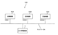
図1に、本発明の実施形態に係るビル管理システム100を示す。本実施形態に係るビル管理システム100は、ビル管理装置1と、設備機器30A,30B,30Cとを含んで構成されている。ビル管理装置1と設備機器30A,30B,30Cとは、オフィスビル等のビル内に設けられたネットワークNに接続されている。ネットワークNは、例えばLAN(Local Area Network)等によって構成されている。図1に示す例では、3つの設備機器(設備機器30A,30B,30C)が示されているが、これらは例示であり、ビル管理システム100は、1又は複数の設備機器を備えていればよい。
FIG. 1 shows a
設備機器30A,30B,30Cは、オフィスビル等のビル内に設置されている機器であり、例えば、プリンタ、ルータ、Webカメラ、電力量計等である。設備機器30A,30B,30Cはそれぞれ通信機能を備え、ネットワークNを介してデータを送受信することができる。設備機器30A,30B,30Cはそれぞれ同じ種別の機器であってもよいし、それぞれ異なる種別の機器であってもよい。設備機器30A,30B,30Cのそれぞれには、ネットワークN上で設備機器30A,30B,30Cのそれぞれを識別するためのアドレスが割り当てられている。例えば、設備機器30A,30B,30Cのそれぞれには、IPアドレス(Internet Protocol Address)が割り当てられている。一例として、設備機器30AにはIPアドレス(10.0.0.1)が割り当てられており、設備機器30BにはIPアドレス(10.0.0.2)が割り当てられており、設備機器30CにはIPアドレス(10.0.0.3)が割り当てられている。
The
ビル管理装置1は、例えば、保守員等の作業者が設備機器の保守を行う場合にネットワークNに一時的に接続される。なお、ビル管理装置1は、ネットワークNに常に接続されていてもよい。
The
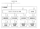
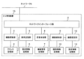
図2に本実施形態に係るビル管理装置1を示す。ビル管理装置1は、ネットワークインターフェース部2と、機器探索部3と、アドレス記憶部4と、要求送信部5と、要求情報記憶部6と、機器管理記憶部7と、応答受信部8と、機器識別部9と、識別情報記憶部10と、出力部11と備えている。
FIG. 2 shows a
ネットワークインターフェース部2は、ネットワークNを介してビル管理装置1の外部にデータを送信し、また、ネットワークNを介してビル管理装置1の外部からデータを受信する。
The
機器探索部3は、ネットワークNに接続されている設備機器30A,30B,30Cを探索し、設備機器30A,30B,30Cのそれぞれに割り当てられているIPアドレスを示すデータをネットワークNを介して取得する。以下の説明では、IPアドレスを示すデータを「IPアドレスデータ」と称する場合がある。例えば、機器探索部3は、ICMP Echo Requestをブロードキャストし、設備機器30A,30B,30CのそれぞれからICMP Echo Replyを受信することにより、設備機器30A,30B,30CのそれぞれのIPアドレスデータを取得する。図3に、機器探索部3によって取得されたIPアドレスの一例を示す。機器探索部3は、設備機器30AからIPアドレス(10.0.0.1)を取得し、設備機器30BからIPアドレス(10.0.0.2)を取得し、設備機器30CからIPアドレス(10.0.0.3)を取得する。
The
機器探索部3は、設備機器30A,30B,30CのそれぞれのIPアドレスデータをアドレス記憶部4に記憶させる。アドレス記憶部4は、設備機器毎に取得されたIPアドレスデータを記憶する。例えば、図3に示すように、アドレス記憶部4は、設備機器毎に取得されたIPアドレスを示すアドレステーブルを記憶する。
The
要求送信部5は、ネットワークNを介して設備機器30A,30B,30Cに所定の要求を送信する。要求情報記憶部6は、要求のリストを示す要求情報テーブルを記憶する。要求送信部5は、アドレス記憶部4に記憶されているアドレステーブルから識別対象の設備機器のIPアドレスを選択し、要求情報記憶部6に記憶されている要求情報テーブルから所定の要求を選択し、当該IPアドレスに対応する設備機器に所定の要求を送信する。設備機器30A,30B,30Cは、要求送信部5から送信された要求に対する応答をネットワークNを介してビル管理装置1に送信する。
The
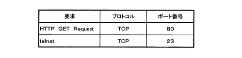
図4に要求の一例を示す。要求情報記憶部6は、要求の内容と、通信プロトコルと、ポート番号とを対応付けた要求情報テーブルを記憶する。要求情報テーブルは予め作成されて要求情報記憶部6に記憶される。要求情報テーブルには、複数の要求と複数の通信プロトコルと複数のポート番号とが対応付けられている。一例として、要求「HTTP GET Request」には通信プロトコル「TCP(Transmission Control Protocol)」が対応付けられ、要求「BACnet Who Is」には通信プロトコル「UDP(User Datagram Protocol)」が対応付けられている。要求送信部5は、「HTTP GET Request」等の要求を図4に示す要求情報テーブルから選択し、ネットワークNを介して設備機器30A,30B,30Cに要求を送信する。
FIG. 4 shows an example of the request. The request information storage unit 6 stores a request information table in which request contents, communication protocols, and port numbers are associated with each other. The request information table is created in advance and stored in the request information storage unit 6. In the request information table, a plurality of requests, a plurality of communication protocols, and a plurality of port numbers are associated. As an example, the communication protocol “TCP (Transmission Control Protocol)” is associated with the request “HTTP GET Request”, and the communication protocol “UDP (User Datagram Protocol)” is associated with the request “BACnet Who Is”. . The
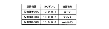
機器管理記憶部7は、機器管理台帳を示すデータ(機器管理テーブル)を記憶する。図5に機器管理台帳の一例を示す。機器管理台帳は、図5に示すように、ビル内に設置されてネットワークNに接続されている設備機器の種別(「機器種別」と称する場合がある)、IPアドレス、及び設置場所等の情報が対応付けられて一覧となった情報である。機器種別とは、ルータやプリンタやWebカメラ等の具体的な設備機器の種類を意味する。機器管理台帳は例えば保守作業で使用される。ビル内に設備機器を設置するときに、保守員等の作業員が機器管理台帳を作成する。ただし、機器管理台帳の作成時の記入ミスや、設備機器を新たに追加したときの機器管理台帳への記入漏れ等によって、ネットワークNに実際に接続されている設備機器と、機器管理台帳に記載されている内容とが一致しない場合がある。なお、機器管理台帳(機器管理テーブル)が「機器管理情報」の一例に相当する。 The device management storage unit 7 stores data (device management table) indicating a device management ledger. FIG. 5 shows an example of the device management ledger. As shown in FIG. 5, the device management ledger is information such as the type of equipment installed in the building and connected to the network N (sometimes referred to as “device type”), IP address, and installation location. Is information that is associated with the list. The device type means a specific type of equipment such as a router, a printer, or a Web camera. The device management ledger is used for maintenance work, for example. When installing equipment in the building, a maintenance worker or the like creates an equipment management ledger. However, due to an entry error when creating a device management ledger or a missing entry in the device management ledger when a new equipment is newly added, it is written in the equipment devices actually connected to the network N and the device management ledger. The contents may not match. The device management ledger (device management table) corresponds to an example of “device management information”.
応答受信部8は、要求送信部5が送信した要求に対する応答を設備機器30A,30B,30CのそれぞれからネットワークNを介して受信し、各応答を機器識別部9に出力する。
The
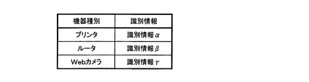
機器識別部9は、応答受信部8が受信した応答に基づいて、設備機器30A,30B,30Cのそれぞれの機器種別を識別する。識別情報記憶部10は、機器識別部9が設備機器の機器種別を識別するための識別情報を記憶する。識別情報は、所定の要求に対して設備機器30A,30B,30Cのそれぞれが送信(返信)し得る応答に該当する情報である。識別情報記憶部10は、機器種別と識別情報とを対応付けた識別情報テーブルを記憶する。要求ごとの識別情報テーブルが予め作成されて、識別情報記憶部10に記憶される。例えば、要求「HTTP GET Request」についての識別情報テーブルと、要求「BACnet Who Is」についての識別情報テーブルとが、識別情報記憶部10に記憶されている。機器識別部9は、応答受信部8が受信した応答と、識別情報記憶部10に記憶されている識別情報とを比較し、その応答に一致する識別情報に対応付けられた機器種別を特定する。このようにして特定された機器種別が、その応答を送信した設備機器の機器種別に該当する。そして、機器識別部9は、設備機器30A,30B,30Cのそれぞれの機器種別とIPアドレスとを対応付ける。
The
図6に識別情報テーブルの一例を示す。図6に示す例では、機器種別(プリンタ)には識別情報αが対応付けられ、機器種別(ルータ)には識別情報βが対応付けられ、機器種別(Webカメラ)には識別情報γが対応付けられている。同じ機器種別であっても、要求が異なると応答も異なるため、応答に相当する識別情報は要求ごとに異なる。 FIG. 6 shows an example of the identification information table. In the example illustrated in FIG. 6, identification information α is associated with a device type (printer), identification information β is associated with a device type (router), and identification information γ is associated with a device type (Web camera). It is attached. Even if the device type is the same, since the response is different if the request is different, the identification information corresponding to the response is different for each request.
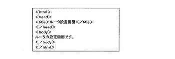
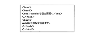
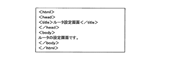
一例として、要求が「HTTP GET Request」である場合の各機器種別の識別情報を図7から図9に示す。図7に示されている識別情報は、プリンタの識別情報αの一例である。すなわち、識別情報αは、要求「HTTP GET Request」に対するプリンタからの応答の内容を示している。図8に示されている識別情報は、ルータの識別情報βの一例である。すなわち、識別情報βは、要求「HTTP GET Request」に対するルータからの応答の内容を示している。図9に示されている識別情報は、Webカメラの識別情報γの一例である。すなわち、識別情報γは、要求「HTTP GET Request」に対するWebカメラからの応答の内容を示している。 As an example, FIG. 7 to FIG. 9 show identification information of each device type when the request is “HTTP GET Request”. The identification information shown in FIG. 7 is an example of printer identification information α. That is, the identification information α indicates the content of a response from the printer to the request “HTTP GET Request”. The identification information shown in FIG. 8 is an example of router identification information β. That is, the identification information β indicates the content of the response from the router to the request “HTTP GET Request”. The identification information shown in FIG. 9 is an example of the identification information γ of the Web camera. That is, the identification information γ indicates the content of a response from the Web camera to the request “HTTP GET Request”.
出力部11は機器識別部9の識別結果を出力する。出力部11は一例として表示装置を備え、識別結果を表示する。例えば、出力部11は、識別結果と機器管理台帳とを並べて表示してもよいし、識別結果と機器管理台帳との差異を表示してもよい。または、出力部11は印刷装置を備え、識別結果を印刷してもよい。
The
次に、図10に示すフローチャートを参照して、本実施形態に係るビル管理装置1による動作の概要を説明する。ビル管理装置1は、機器探索ステップ(ステップS01)と機器識別ステップ(ステップS02)とを実行することで、設備機器30A,30B,30Cのそれぞれの機器種別とIPアドレスとを識別して対応付ける。機器探索ステップ(ステップS01)では、ビル管理装置1は、ネットワークNに接続されている設備機器を探索し、設備機器のIPアドレスデータをネットワークNを介して取得する。次に、機器識別ステップ(ステップS02)では、ビル管理装置1は、機器探索ステップにて取得したIPアドレスに対応する設備機器の機器種別を識別する。
Next, with reference to the flowchart shown in FIG. 10, the outline | summary of operation | movement by the
次に、機器探索ステップ(ステップS01)及び機器識別ステップ(ステップS02)の詳細を説明する。機器探索ステップ(ステップS01)では、機器探索部3がネットワークNに接続されている設備機器30A,30B,30Cを探索し、設備機器30A,30B,30CのそれぞれのIPアドレスデータをネットワークNを介して取得する。一例として、機器探索部3は設備機器30AからIPアドレス(10.0.0.1)を取得し、設備機器30BからIPアドレス(10.0.0.2)を取得し、設備機器30CからIPアドレス(10.0.0.3)を取得する。この機器探索ステップ(ステップS01)によって、ネットワークNには3台の設備機器(設備機器30A,30B,30C)が接続されていることと、それら3台の設備機器のIPアドレスが判明する。機器探索ステップ(ステップS01)の段階では、設備機器30A,30B,30Cのそれぞれの機器種別は判明しておらず未知である。アドレス記憶部4は、機器探索部3によって取得されたIPアドレスを図3に示すように、設備機器毎に取得されたIPアドレスを示すアドレステーブルを記憶する。そして、処理は機器識別ステップ(ステップS02)へ移行する。
Next, details of the device search step (step S01) and the device identification step (step S02) will be described. In the device search step (step S01), the
図11及び図12を参照して、機器識別ステップ(ステップS02)の詳細を説明する。図11は、機器識別ステップ(ステップS02)の詳細を示すフローチャートである。図12は、ビル管理装置1の動作を説明するための図である。
With reference to FIG.11 and FIG.12, the detail of an apparatus identification step (step S02) is demonstrated. FIG. 11 is a flowchart showing details of the device identification step (step S02). FIG. 12 is a diagram for explaining the operation of the
まず、要求送信部5は、アドレス記憶部4に記憶されているアドレステーブルから識別対象の設備機器のIPアドレスを選択する(ステップS10)。例えば、要求送信部5は、図3に示すIPアドレスの一覧から識別対象の設備機器のIPアドレスを選択する。選択の基準は任意でよい。例えば、要求送信部5は、IPアドレスデータが取得された時間の順序に従ってIPアドレスを選択してもよいし、IPアドレスの値に基づく順序に従ってIPアドレスを選択してもよい。ここでは、要求送信部5が、設備機器30AのIPアドレス(10.0.0.1)を選択した場合について説明する。
First, the
要求送信部5は、要求情報記憶部6に記憶されている要求情報テーブルから所定の要求を選択する(ステップS11)。例えば、要求送信部5は、図4に示す要求情報の一覧から要求を選択する。選択の基準は任意でよい。例えば、要求に優先順位を予め付けておき、要求送信部5は、その優先順位に従って要求を選択してもよい。ここでは、要求送信部5が、「HTTP GET Request」を選択した場合について説明する。なお、ステップS10,S11は、処理の順番が逆であってもよいし、同時に行われてもよい。
The
そして、要求送信部5は、選択したIPアドレスに対応する設備機器30Aに対して、選択した要求をネットワークNを介して送信する(ステップS12)。例えば図12に示すように、要求送信部5は、IPアドレス(10.0.0.1)に対応する設備機器30Aに対して、要求Aである「HTTP GET Request」を送信する。
Then, the
設備機器30Aは、ビル管理装置1から送信された要求を受信すると、その要求に対応する応答をネットワークNを介してビル管理装置1に送信する。例えば図12に示すように、設備機器30Aは、要求Aである「HTTP GET Request」に対応する「HTTP Response」を応答Aとしてビル管理装置1に送信する。図13に、設備機器30Aからの応答Aの一例を示す。
Upon receiving the request transmitted from the
応答受信部8は、ネットワークNを介して設備機器30Aから応答Aを受信し、その応答Aを機器識別部9に出力する(ステップS13)。
The
機器識別部9は、応答Aに基づいて設備機器30Aの機器種別を識別する。機器識別部9は、識別情報記憶部10に記憶されている識別情報テーブルを参照し、応答Aに一致する識別情報を検索する(ステップS14)。要求が「HTTP GET Request」であるため、機器識別部9は、その要求「HTTP GET Request」についての識別情報テーブルを参照し、応答Aに一致する識別情報を検索する。応答Aに一致する識別情報が識別情報テーブルに含まれている場合(ステップS15,Yes)、設備機器30Aの機器種別の識別に成功したことになり、設備機器30Aに対する識別処理を終了する(ステップS16)。応答Aに一致する識別情報に対応付けられた機器種別が、設備機器30Aの機器種別に該当する。
The
一方、応答Aに一致する識別情報が識別情報テーブルに含まれておらず(ステップS15,No)、要求送信部5が要求情報テーブルから全ての要求を選択していない場合(ステップS17,No)、要求送信部5は要求情報テーブルから別の要求を選択する(ステップS11)。そして、ステップS11からステップS15までの処理を設備機器30Aに対して行う。一方、要求送信部5が要求情報テーブルから全ての要求を選択している場合(ステップS17,Yes)、設備機器30Aの機器種別の識別に失敗したことになり、設備機器30Aに対する識別処理は終了する(ステップS18)。このように、応答Aに一致する識別情報が識別情報テーブルに含まれていない場合(ステップS15,No)、要求送信部5は、要求情報テーブルから次の要求を選択して設備機器30Aに送信する。この処理を、応答Aに一致する識別情報が識別情報テーブル内で見つかるか、要求情報テーブルに含まれる全ての要求を設備機器30Aに送信するまで繰り返す。
On the other hand, when the identification information matching the response A is not included in the identification information table (No at Step S15), and the
設備機器30Aに対する識別処理が終了し、要求送信部5がアドレステーブルから全てのIPアドレスを選択していない場合(ステップS19,No)、要求送信部5はアドレステーブルから別のIPアドレスを選択する(ステップS10)。そして、そのIPアドレスに対応する設備機器に対して、ステップS11からステップS18までの処理を行う。一方、要求送信部5がアドレステーブルから全てのIPアドレスを選択している場合(ステップS19,Yes)、一連の識別処理は終了する。
When the identification processing for the equipment 30A is completed and the
一例として、図13に示す設備機器30Aからの応答Aは、図8に示す識別情報βと一致する。識別情報βはルータからの応答の内容を示しているため、設備機器30Aの機器種別はルータであると識別される。 As an example, the response A from the equipment 30A shown in FIG. 13 matches the identification information β shown in FIG. Since the identification information β indicates the content of the response from the router, the equipment type of the equipment 30A is identified as a router.
一方、要求「HTTP GET Request」に対する設備機器30Aからの応答が予め設定された期間内にない場合や、要求「HTTP GET Request」に対応する応答Aと一致する識別情報が識別情報テーブルに含まれていない場合、要求送信部5は、要求「HTTP GET Request」以外の要求を要求情報テーブルから選択して設備機器30Aに送信する。例えば、要求送信部5は、図4に示す「BACnet Who Is」を要求情報テーブルから選択して設備機器30Aに送信する。この処理を、応答Aに一致する識別情報が識別情報テーブル内で見つかるか、要求情報テーブルに含まれる全ての要求を設備機器30Aに送信するまで繰り返す。
On the other hand, when the response from the equipment 30A to the request “HTTP GET Request” is not within a preset period, the identification information table includes identification information that matches the response A corresponding to the request “HTTP GET Request”. If not, the
設備機器30B,30Cに対しても設備機器30Aと同様の処理を行う。すなわち、図12に示すように、ビル管理装置1は、ネットワークNを介して設備機器30Bに要求Bを送信し、その要求Bに対応する応答Bを設備機器30BからネットワークNを介して受信し、その応答Bと識別情報テーブルに含まれる識別情報を比較することで設備機器30Bの機器種別を識別する。同様に、ビル管理装置1は、ネットワークNを介して設備機器30Cに要求Cを送信し、その要求Cに対応する応答Cを設備機器30CからネットワークNを介して受信し、応答Cと識別情報テーブルに含まれる識別応報とを比較することで設備機器30Cの機器種別を識別する。
The same processing as that for the equipment 30A is performed for the
図14に、各設備機器のIPアドレスと各設備機器からの応答との対応関係を示す。図14に示す応答「HTTP Response」は、要求「HTTP GET Request」に対する応答である。例えば、設備機器30A(10.0.0.1)の応答Aは図8に示す識別情報βと一致し、設備機器30B(10.0.0.2)の応答Bは図7に示す識別情報αと一致し、設備機器30C(10.0.0.3)の応答Cは図9に示す識別情報γと一致する。
FIG. 14 shows the correspondence between the IP address of each equipment device and the response from each equipment device. The response “HTTP Response” illustrated in FIG. 14 is a response to the request “HTTP GET Request”. For example, the response A of the equipment 30A (10.0.0.1) matches the identification information β shown in FIG. 8, and the response B of the
機器識別部9は、図14に示す情報と、図6に示す識別情報テーブルとを比較することで、設備機器30A,30B,30Cのそれぞれの機器種別と機器種別とを対応付ける。
The
図15に、機器識別部9によって得られた識別結果の一例を示す。例えば、設備機器30A(10.0.0.1)からの応答Aが、識別情報テーブル内の「ルータ」の識別情報βと一致するため、設備機器30A(10.0.0.1)の機器種別は「ルータ」であることが判明する。従って、機器識別部9は、設備機器30Aの機器種別「ルータ」と、IPアドレス「10.0.0.1」とを対応付ける。また、設備機器30B(10.0.0.2)からの応答Bが、識別情報テーブル内の「プリンタ」の識別情報αと一致するため、設備機器30B(10.0.0.2)の機器種別は「プリンタ」であることが判明する。従って、機器識別部9は、設備機器30Bの機器種別「プリンタ」と、IPアドレス「10.0.0.2」とを対応付ける。また、設備機器30C(10.0.0.3)からの応答Cが、識別情報テーブル内の「Webカメラ」の識別情報γと一致するため、設備機器30Cの種別は「Webカメラ」であることが判明する。従って、機器識別部9は、設備機器30Cの機器種別「Webカメラ」と、IPアドレス「10.0.0.3」とを対応付ける。機器識別部9は識別結果を出力部11に出力する。また、機器識別部9は、図示しない記憶装置に識別結果を記憶させてもよい。上記の例では、機器識別部9は、図15に示す対応関係を識別結果として出力部11に出力する。
FIG. 15 shows an example of the identification result obtained by the
出力部11は機器識別部9の識別結果を出力する。例えば、出力部11は、図15に示す識別結果の一覧表を表示する。また、出力部11は、図15に示す識別結果の一覧表と、図5に示す機器管理台帳(機器管理テーブル)とを並べて表示してもよい。それにより、識別結果と機器管理台帳の設備機器毎のIPアドレスとの差異の有無が分かる。また、出力部11は、機器識別部9の識別結果と機器管理台帳とを比較し、識別結果と機器管理台帳との差異を表示してもよい。例えば、出力部11は、機器種別とIPアドレスとの対応付けが識別結果と機器管理台帳とで異なる設備機器を保守員等の作業員が認識できるように、その異なる設備機器の機器種別やIPアドレスを、他の機器設備の機器種別やIPアドレスとは異なる色で表示したり、ハイライトで表示したりしてもよい。
The
以上のように、本実施形態に係るビル管理装置1によると、ネットワークNに接続されている設備機器30A,30B,30Cの機器種別と、設備機器30A,30B,30CのそれぞれのIPアドレスとを容易に識別して対応付けることが可能となる。また、要求情報テーブルに複数の異なる通信プロトコルを規定しておくことで、ある通信プロトコルでは応答が得られない場合であっても、別の通信プロトコルでは応答が得られる場合があるため、複数の通信プロトコルに対応して設備機器の機器種別を識別することができる。
As described above, according to the
また、機器識別部9の識別結果は、ネットワークNに実際に接続されている設備機器の機器種別とIPアドレスとを示しているため、保守員等の作業員は識別結果と機器管理台帳とを比較することで、機器管理台帳の内容とネットワークに実際に接続されている設備機器との差異を確認することができる。例えば、機器管理台帳の作成時の記入ミスや、設備機器を新たに追加したときの機器管理台帳への反映漏れ等によって、実際に設置されている設備機器と機器管理台帳に記載されている内容とが一致しない場合であっても、識別結果と機器管理台帳とを比較することで、記入ミスや反映漏れ等を発見することができる。
In addition, since the identification result of the
また、識別結果と機器管理台帳とが一致しない場合、保守員等の作業員が図示しない入力装置を用いて、機器管理台帳又は識別結果を修正できるようにしてもよいし、識別結果を新たな機器管理台帳として選択できるようにしてもよい。新たな機器管理台帳として選択された識別結果は、機器管理記憶部7に記憶される。 If the identification result and the device management ledger do not match, an operator such as a maintenance staff may use an input device (not shown) to correct the device management ledger or the identification result, or the identification result You may make it selectable as an apparatus management ledger. The identification result selected as the new device management ledger is stored in the device management storage unit 7.
また、機器識別部9によって機器種別が識別されなかった設備機器(識別に失敗した設備機器)がある場合、出力部11は、その結果を表示してもよい。例えば、IPアドレスは取得できたが、機器種別が識別されなかった設備機器がある場合、出力部11は、機器種別が識別されなかった設備機器のIPアドレスを表示する。この場合、保守員等の作業員が入力装置を用いて、機器種別が識別されなかった設備機器の機器種別を入力できるようにしてもよい。機器識別部9は、機器種別が識別されなかった設備機器のIPアドレスと入力装置から入力された機器種別とを対応付けて、識別結果とともに図示しない記憶装置に記憶させる。また、機器種別が識別されなかった設備機器のIPアドレスと機器種別とが機器管理台帳に含まれていない場合、機器識別部9は、機器種別が識別されなかった設備機器のIPアドレスと入力装置から入力された機器種別とを対応付けて機器管理台帳に追加し、機器管理台帳を更新してもよい。また、設備機器から送信された応答と一致する識別情報が識別情報テーブルに含まれていないために設備機器の機器種別が識別されていない場合、機器識別部9は、機器種別が識別されなかった設備機器から送信された応答(識別情報)と入力装置から入力された機器種別とを対応付けて識別情報テーブルに追加し、識別情報テーブルを更新してもよい。以上のように、機器種別が識別されなかった設備機器のIPアドレスを表示することで、保守員等の作業員は、機器管理台帳や識別情報テーブルに規定されていない設備機器がネットワークNに接続されていることを見つけ出すことができる。
When there is an equipment device whose equipment type has not been identified by the equipment identifying unit 9 (an equipment device that has failed to be identified), the
次に、図16を参照して、本実施形態に係るビル管理装置1の適用例について説明する。例えば、ビル60内には、情報収集装置40と設備コントローラ41と監視カメラ42とが、設備機器の一例として設置されている。情報収集装置40と設備コントローラ41と監視カメラ42とは、ビル60内に構築されたネットワークNに接続されている。情報収集装置40は、例えば温度計、湿度計及び電力量計等であり、ビル60内の温度、湿度及び電力量等を計測する。設備コントローラ41は、ネットワークNに接続されている他の設備機器の動作を制御する装置である。
Next, an application example of the
設備機器の設置や保守を行う場合、保守員はビル管理装置1をネットワークNに接続する。ビル管理装置1は、上述したように、情報収集装置40、設備コントローラ41及び監視カメラ42のそれぞれのIPアドレスデータを取得し、さらに、情報収集装置40、設備コントローラ41及び監視カメラ42のそれぞれの機器種別を識別する。そして、ビル管理装置1は、情報収集装置40、設備コントローラ41及び監視カメラ42のそれぞれの機器種別とIPアドレスデータとを対応付ける。図16に示す例では、ビル管理装置1によって、情報収集装置40とIPアドレス「10.0.0.1」とが対応付けられ、設備コントローラ41とIPアドレス「10.0.0.2」とが対応付けられ、監視カメラ42とIPアドレス「10.0.0.4」とが対応付けられる。一方、機器管理台帳50によると、情報収集装置40とIPアドレス「10.0.0.1」とが対応付けられ、設備コントローラ41とIPアドレス「10.0.0.2」とが対応付けられ、監視カメラ42とIPアドレス「10.0.0.3」とが対応付けられている。保守員は、機器管理台帳50の内容とビル管理装置1によって得られた識別結果とを比較することで、両者の差異を認識することができる。機器管理台帳50によると監視カメラ42のIPアドレスは「10.0.0.3」であるが、識別結果によると監視カメラ42のIPアドレスは「10.0.0.4」であることが判明している。従って、保守員は機器管理台帳50と識別結果とを比較することで、機器管理台帳50の誤りを発見することができる。
When installing and maintaining the equipment, the maintenance staff connects the
(変形例1)
次に、図17から図20を参照して、変形例1に係るビル管理システムについて説明する。変形例1に係るビル管理装置は、設備機器の機器種別とIPアドレスとを識別して対応付けた後、設備機器の設定を自動的に行う。
(Modification 1)
Next, a building management system according to
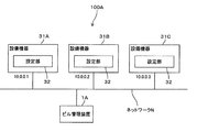
図17に、変形例1に係るビル管理システム100Aを示す。変形例1に係るビル管理システム100Aは、ビル管理装置1Aと、設備機器31A,31B,31Cとを含んで構成されている。ビル管理装置1Aと設備機器31A,31B,31Cとは、オフィスビル等のビル内に設けられたネットワークNに接続されている。
FIG. 17 shows a
設備機器31A,31B,31Cは、上述した設備機器30A等と同様に、プリンタ、ルータ、Webカメラ、電力量計等である。変形例1においては、設備機器31A,31B,31Cはそれぞれ設定部32を備えている。設定部32は、自身の設備機器の動作条件を設定する。設定部32による設定内容としては、例えば、ルータのパケットフィルタの設定やWebカメラの角度調整等が該当する。設定部32以外の構成及び機能については、設備機器31A,31B,31Cは、上述した設備機器30A,30B,30Cと同じ構成及び機能を有する。
The
図18に変形例1に係るビル管理装置1Aを示す。ビル管理装置1Aは、上述したビル管理装置1の構成に加えて、機器設定部12と設定情報記憶部13とを備えている。なお、図18には出力部11が示されていないが、ビル管理装置1Aは出力部11を備えていてもよい。機器設定部12及び設定情報記憶部13以外の構成及び機能については、ビル管理装置1Aは、上述したビル管理装置1と同じ構成及び機能を有する。
FIG. 18 shows a
機器設定部12は、設備機器31A,31B,31Cの設定部32にネットワークNを介して接続し、設定部32を制御して設定情報に基づいて設備機器31A,31B,31Cの動作条件を設定する。
The
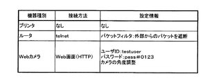
設定情報記憶部13は、設備機器の機器種別ごとの設定情報と、設定部32への接続方法とを対応付けた設定情報テーブルを記憶する。設定情報テーブルは予め作成されて設定情報記憶部13に記憶される。図19に設定情報テーブルの一例を示す。設定情報テーブルにおいては、機器種別と、設定部32への接続方法と、設定項目及びパラメータを示す設定情報とが対応付けられている。例えば、設定情報が、各設備機器の初期設定の内容を示していてもよい。
The setting
次に、変形例1に係るビル管理装置1Aによる動作を図20に示すフローチャートを参照して説明する。ビル管理装置1Aは、上述したビル管理装置1と同様に、機器探索ステップ(ステップS01)と機器識別ステップ(ステップS02)とを実行することで、設備機器31A,31B,31Cのそれぞれの機器種別とIPアドレスとを識別して対応付ける。次に、ビル管理装置1Aは、機器設定ステップ(ステップS03)を実行することで、機器識別ステップ(ステップS02)にて識別された設備機器の動作条件を設定する。
Next, the operation of the
機器設定ステップ(ステップS03)では、機器設定部12は、設備機器31A,31B,31Cの設定部32にネットワークNを介して接続し、設定部32を制御して設定情報テーブルに含まれる設定情報に基づいて設備機器31A,31B,31Cの動作条件を設定する。図19に示す例では、機器設定部12は、機器種別が「ルータ」の設備機器に対しては「telnet」で接続し、パケットフィルタの設定を行う。また、機器設定部12は、機器種別が「Webカメラ」の設備機器に対しては「HTTP」で接続し、Webカメラの角度を調整する。
In the device setting step (step S03), the
なお、管理者等の作業員が、設定対象となる設備機器と設定情報とを選択してもよい。例えば、図示しない表示装置によって設定情報テーブルを表示し、作業員が図示しない入力装置を用いて設定対象となる設備機器と設定情報とを選択する。機器設定部12は、作業員によって選択された設定情報に基づいて、作業員によって選択された設備機器の動作条件を設定する。図19に示す例では、1つの機器種別に対して1つの設定情報が対応付けられているが、1つの機器種別に対して複数の設定情報が対応付けられていてもよい。この場合、作業員が入力装置を用いて所望の設定情報を選択すればよい。
Note that an operator such as an administrator may select the equipment to be set and the setting information. For example, a setting information table is displayed on a display device (not shown), and an operator selects facility equipment and setting information to be set using an input device (not shown). The
以上のように、変形例1に係るビル管理装置1Aによると、上述したビル管理装置1による効果に加えて、設備機器31A,31B,31Cの動作条件を自動的に設定することが可能となる。例えば、ビル内のネットワークNに設備機器を接続した後、ビル管理装置1AをネットワークNに接続し、上記のステップS01,S02,S03を実行することで、設備機器の機器種別とIPアドレスとを自動的に識別し、更に、設定情報に基づいて各設備機器の動作条件を自動的に設定することができる。そのことにより、従来は設備機器の動作条件を手動で設定していた作業を自動で行うことができ、ビル内での設備機器の設置及び設定作業を効率的に行うことができる。
As described above, according to the
(変形例2)
次に、図21及び図22を参照して、変形例2に係るビル管理システムについて説明する。変形例2に係るビル管理システムは、上述したビル管理システム100と同じ構成を有し、変形例2に係るビル管理装置は、上述したビル管理装置1と同じ構成を有する。変形例2においては、要求送信部5は、各設備機器に対して複数の異なる要求を送信し、応答受信部8は、複数の異なる要求のそれぞれに対応する複数の応答を受信し、機器識別部9は、複数の応答の組み合わせに基づいて設備機器の種別を識別する。
(Modification 2)
Next, with reference to FIG.21 and FIG.22, the building management system which concerns on the
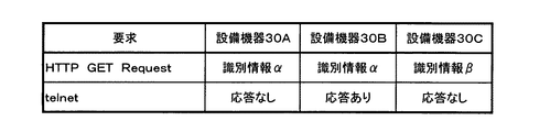
図21に、変形例2に係る要求情報テーブルの一例を示す。図22に、変形例2に係る識別情報テーブルの一例を示す。図21に示す要求情報テーブルは予め作成されて要求情報記憶部6に記憶され、図22に示す識別情報テーブルは予め作成されて識別情報記憶部10に記憶されている。変形例2に係る識別情報テーブルでは、要求と各設備機器の識別情報とが対応付けられている。例えば図22に示す例では、要求が「HTTP GET Request」の場合、設備機器30Aが送信(返信)し得る応答は識別情報αであり、設備機器30Bが送信し得る応答は識別情報αであり、設備機器30Cが送信し得る応答は識別情報βである。この場合、要求「HTTP GET Request」に対応する応答(識別情報)が、設備機器30Aと設備機器30Bとで同一であるため、要求「HTTP GET Request」の応答だけでは、設備機器30Aと設備機器30Bとを識別することができない。そこで、要求送信部5は、別の要求を設備機器30Aと設備機器30Bとに送信し、応答受信部8は、その別の要求に対応する応答を設備機器30Aと設備機器30Bとから受信する。図21に示す例では、要求送信部5は、次の要求「telnet」によって設備機器30Aと設備機器30Bとに対して通信を行い、応答受信部8は、要求「telnet」に対する応答を受信する。図22に示す例では、要求「telnet」に対する応答は、設備機器30Aと設備機器30Bとで異なるため、機器識別部9は、要求「HTTP GET Request」に対する応答と、要求「telnet」に対する応答とを組み合わせることで、設備機器30Aと設備機器30Bとを識別することができる。例えば、要求「HTTP GET Request」に対して識別情報αを返信し、要求「telnet」に対して予め設定された期間内に応答しない設備機器は、設備機器30Aである。一方、要求「HTTP GET Request」に対して識別情報αを返信し、要求「telnet」に対して予め設定され期間内に応答する設備機器は、設備機器30Bである。
FIG. 21 shows an example of the request information table according to the second modification. FIG. 22 shows an example of the identification information table according to the second modification. The request information table shown in FIG. 21 is created in advance and stored in the request information storage unit 6, and the identification information table shown in FIG. 22 is created in advance and stored in the identification
なお、要求送信部5は、すべての設備機器30A,30B,30Cに対して複数の異なる要求を送信し、機器識別部9は、複数の異なる要求に対応する複数の応答の組み合わせに基づいて、設備機器30A,30B,30Cの機器種別を識別してもよい。
The
または、要求送信部5は、設備機器30A,30B,30Cのそれぞれに対して1つの要求を送信し、応答が同一となった複数の設備機器に対して更に別の要求を送信し、機器識別部9は、複数の応答の組み合わせに基づいて、応答が一部で同一となる複数の設備機器のそれぞれの機器種別を識別してもよい。例えば、要求送信部5は、設備機器30A,30B,30Cのそれぞれに対して第1の要求を送信する。設備機器30Aからの応答と設備機器30Bからの応答とが同一になった場合、要求送信部5は、設備機器30A,30Bに対して第1の要求とは異なる第2の要求を送信する。機器識別部9は、第1の要求に対する応答と第2の要求に対する応答との組み合わせに基づいて、設備機器30A,30Bの機器種別を識別する。また、機器識別部9は、第1の要求に対する応答に基づいて設備機器30Cの機器種別を識別する。なお、第2の要求に対する応答も設備機器30A,30Bで同じになった場合、要求送信部5は、第1及び第2の要求とは異なる第3の要求を設備機器30A,30Bに送信してもよい。機器識別部9は、第1、第2及び第3の要求のそれぞれに対する応答に基づいて、設備機器30A,30Bの機器種別を識別する。なお、1又は複数の応答が同一となる複数の設備機器の機器種別を同一と判断してもよい。
Or the
(変形例3)
次に、変形例3に係るビル管理システムについて説明する。変形例3に係るビル管理システムは、上述したビル管理システム100,100Aと同じ構成を有し、変形例3に係るビル管理装置は、上述したビル管理装置1,1Aと同じ構成を有する。変形例3においては、機器識別部9は、設備機器からの応答と一部が一致する識別情報を識別情報テーブルから検索し、その識別情報に対応付けら機器種別を特定する。このようにして特定された機器種別が、その応答を送信した設備機器の機器種別であると推定される。例えば、機器識別部9は、予め設定されたキーワードを応答から抽出し、そのキーワードを含む識別情報を識別情報テーブルから検索し、その識別情報に対応付けられた機器種別を設備機器の機器種別であると推定する。キーワードは例えば機器種別を特定する文字列であり、一例として「プリンタ」、「ルータ」、「Webカメラ」等である。
(Modification 3)
Next, the building management system which concerns on the
一例として、図13に示す応答が設備機器から得られた場合について説明する。機器識別部9は、予め設定されたキーワード「ルータ」を図3に示す応答から抽出し、そのキーワードである「ルータ」を含む識別情報を識別情報テーブルから検索する。例えば図8に示す識別情報βはルータの識別情報であり、識別情報βにはキーワードである「ルータ」が含まれている。従って、機器識別部9は、識別情報βに対応付けられた機器種別「ルータ」を、応答を送信した設備機器の機器種別であると推定する。
As an example, a case where the response shown in FIG. 13 is obtained from the equipment will be described. The
設備機器の設定内容の違いやバージョンの違いによって、同じ機器種別の設備機器であっても、要求に対する応答(識別情報)が異なる場合がある。応答と一部が一致する識別情報に対応付けられた機器種別を設備機器の機器種別であると推定することで、応答と完全に一致する識別情報が識別情報テーブルに含まれていない場合でも、設備機器の機器種別を推定し、設備機器の機器種別とIPアドレスとを対応付けることができる。 Depending on the setting contents of the equipment and the version, the response (identification information) to the request may be different even for equipment of the same equipment type. Even if the identification information table does not contain identification information that completely matches the response by estimating that the device type associated with the identification information that partially matches the response is the device type of the equipment device, The equipment type of the equipment can be estimated, and the equipment type of the equipment can be associated with the IP address.
(変形例4)
上述した識別情報テーブルや設定情報テーブルを、ネットワークNに接続された図示しないサーバに保存してもよい。なお、このサーバは、ビル内又はビル外のいずれに設置されていてもよく、ビル管理装置1,1Aと有線や無線のネットワーク、インターネット等を介して通信できればよい。ビル管理装置1,1Aは、そのサーバにアクセスして識別情報テーブルを参照することで設備機器の機器種別を識別する。この場合、ビル管理装置1,1Aは識別情報記憶部10を備えていなくてもよい。また、ビル管理装置1Aは、設定情報テーブルに関しても同様にそのサーバにアクセスするようにすれば、設定情報記憶部13を備えていなくてもよい。
(Modification 4)
The above-described identification information table and setting information table may be stored in a server (not shown) connected to the network N. This server may be installed either inside or outside the building, as long as it can communicate with the
(ハードウェア構成)
上述したビル管理装置1,1Aの機器探索部3、要求送信部5、応答受信部8、機器識別部9及び機器設定部12は、例えばハードウェア資源とソフトウェア資源との協働によって実現されてもよい。具体的には、機器探索部3、要求送信部5、応答受信部8、機器識別部9及び機器設定部12のそれぞれの機能は、記憶媒体に記憶されたプログラムがメインメモリに読み出されてCPU(Central Processing Unit)により実行されることによって実現される。このプログラムは、コンピュータ読み取り可能な記憶媒体に記憶されて提供されることも可能であるし、データ通信として通信により提供されることも可能である。また、ビル管理装置1は、物理的に1つの装置により実現されてもよいし、複数の装置により実現されてもよい。
(Hardware configuration)
The
また、設備機器31A,31B,31Cの設定部32は、例えばハードウェア資源とソフトウェア資源との協働により実現されてもよい。設定部32の機能は、記憶媒体に記憶されたプログラムがメインメモリに読み出されてCPUにより実行されることによって実現される。このプログラムは、コンピュータ読み取り可能な記憶媒体に記憶されて提供されることも可能であるし、データ通信として通信により提供されることも可能である。
The setting
1,1A ビル管理装置、2 ネットワークインターフェース部、3 機器探索部、4 アドレス記憶部、5 要求送信部、6 要求情報記憶部、7 機器管理記憶部、8 応答受信部、9 機器識別部、10 識別情報記憶部、11 出力部、12 機器設定部、13 設定情報記憶部、30A,30B,30C,31A,31B,31C 設備機器、32 設定部、40 情報収集装置、41 設備コントローラ、42 監視カメラ、50 機器管理台帳、60 ビル、100,100A ビル管理システム。 1, 1A building management device, 2 network interface unit, 3 device search unit, 4 address storage unit, 5 request transmission unit, 6 request information storage unit, 7 device management storage unit, 8 response reception unit, 9 device identification unit, 10 Identification information storage unit, 11 output unit, 12 device setting unit, 13 setting information storage unit, 30A, 30B, 30C, 31A, 31B, 31C equipment device, 32 setting unit, 40 information collecting device, 41 equipment controller, 42 surveillance camera , 50 device management ledger, 60 building, 100, 100A building management system.
Claims (10)
前記アドレスデータによって特定される前記複数の設備機器のそれぞれに前記ネットワークを介して所定の要求を送信する要求送信手段と、
前記要求に対応する応答を前記ネットワークを介して前記複数の設備機器のそれぞれから受信する応答受信手段と、
前記応答に基づいて前記複数の設備機器のそれぞれの種別を識別する機器識別手段と、
を有し、
前記要求送信手段は、前記複数の設備機器のそれぞれに第1の要求を送信し、前記複数の設備機器のうち前記第1の要求に対応する応答が他の設備機器と同じになった設備機器に対して、前記第1の要求とは異なる第2の要求を送信し、
前記機器識別手段は、前記第1の要求に対応する応答が他の設備機器と同じになった設備機器については、前記第1の要求に対応する応答と、前記第2の要求に対応する応答と、に基づいて種別を識別し、前記第1の要求に対応する応答が他の設備機器とは異なる設備機器については、前記第1の要求に対応する応答に基づいて種別を識別する、
ことを特徴とするビル管理装置。 It is installed in a building and searching a plurality of equipment connected to the network of said building, the address data allocated in advance to each of the plurality of equipment of the plurality of equipment through the network A device search means to acquire from each ;
Request transmitting means for transmitting a predetermined request to each of the plurality of facility devices specified by the address data via the network;
Response receiving means for receiving a response corresponding to the request from each of the plurality of facility devices via the network;
A device identifying means for identifying each type of the plurality of facility devices based on the response;
I have a,
The request transmitting means transmits a first request to each of the plurality of facility devices, and the facility device in which a response corresponding to the first request among the plurality of facility devices is the same as other facility devices. To send a second request different from the first request,
The equipment identifying means, for equipment whose response corresponding to the first request is the same as other equipment, is a response corresponding to the first request and a response corresponding to the second request. And identifying a type based on the response, and for a facility device whose response corresponding to the first request is different from other facility devices, identifying the type based on the response corresponding to the first request,
A building management device characterized by that.
前記機器識別手段は前記応答の一部に基づいて前記設備機器を識別する、
ことを特徴とするビル管理装置。 The building management device according to claim 1 ,
The device identifying means identifies the facility device based on a part of the response;
A building management device characterized by that.
前記機器識別手段による識別結果を出力する出力手段を更に有する、
ことを特徴とするビル管理装置。 The building management device according to claim 1 or 2 ,
It further has an output means for outputting the identification result by the device identification means.
A building management device characterized by that.
前記ネットワークに接続されている前記設備機器の種別とアドレスデータとの対応付けを示す機器管理情報を予め記憶する機器管理記憶手段を更に有し、
前記出力手段は、前記識別結果と、前記機器管理記憶手段に記憶されている前記機器管理情報との差異を出力する、
ことを特徴とするビル管理装置。 The building management device according to claim 3 ,
Further comprising device management storage means for storing in advance device management information indicating a correspondence between the type of the facility device connected to the network and address data;
The output means outputs a difference between the identification result and the device management information stored in the device management storage means;
A building management device characterized by that.
前記出力手段は、前記機器識別手段によって識別されなかった設備機器に割り当てられているアドレスデータを出力する、
ことを特徴とするビル管理装置。 The building management device according to claim 3 ,
The output means outputs address data assigned to the equipment not identified by the equipment identification means;
A building management device characterized by that.
前記機器識別手段によって識別された設備機器の動作条件を前記ネットワークを介して設定する機器設定手段を更に有する、
ことを特徴とするビル管理装置。 The building management device according to any one of claims 1 to 5 ,
Further comprising a device setting means for setting the operating condition of the equipment device identified by the device identifying means via the network,
A building management device characterized by that.
前記機器識別手段は、要求に対して前記設備機器から返信され得る応答に該当する情報である識別情報を取得し、前記設備機器からの前記応答と前記識別情報とに基づいて前記設備機器の種別を識別する、
ことを特徴とするビル管理装置。 The building management device according to any one of claims 1 to 6 ,
Said device identification unit acquires the identification information, which is information corresponding to the response that may be returned from the equipment with respect to requests, of the equipment on the basis of said response and said identification information from said equipment Identify the type,
A building management device characterized by that.
前記機器識別手段は、前記ネットワークに接続されたサーバから前記識別情報を取得して前記設備機器の種別を識別する、
ことを特徴とするビル管理装置。 The building management device according to claim 7 ,
The device identifying means acquires the identification information from a server connected to the network and identifies the type of the facility device.
A building management device characterized by that.
前記ビル管理装置は、
前記ネットワークに接続されている前記複数の設備機器を探索し、前記複数の設備機器のそれぞれに予め割り当てられているアドレスデータを前記ネットワークを介して前記複数の設備機器のそれぞれから取得する機器探索手段と、
前記アドレスデータによって特定される前記複数の設備機器のそれぞれに前記ネットワークを介して所定の要求を送信する要求送信手段と、
前記要求に対応する応答を前記ネットワークを介して前記複数の設備機器のそれぞれから受信する応答受信手段と、
前記応答に基づいて前記複数の設備機器のそれぞれの種別を識別する機器識別手段と、
を有し、
前記要求送信手段は、前記複数の設備機器のそれぞれに第1の要求を送信し、前記複数の設備機器のうち前記第1の要求に対応する応答が他の設備機器と同じになった設備機器に対して、前記第1の要求とは異なる第2の要求を送信し、
前記機器識別手段は、前記第1の要求に対応する応答が他の設備機器と同じになった設備機器については、前記第1の要求に対応する応答と、前記第2の要求に対応する応答と、に基づいて種別を識別し、前記第1の要求に対応する応答が他の設備機器とは異なる設備機器については、前記第1の要求に対する応答に基づいて種別を識別する、
ことを特徴とするビル管理システム。 A building management system in which a plurality of equipment installed in a building and a building management apparatus are connected via a network in the building,
The building management device
Searching the plurality of facility devices connected to the network, the plurality of facility devices searching means for acquiring from each of said plurality of equipment through the network address data assigned in advance to each device When,
Request transmitting means for transmitting a predetermined request to each of the plurality of facility devices specified by the address data via the network;
Response receiving means for receiving a response corresponding to the request from each of the plurality of facility devices via the network;
A device identifying means for identifying each type of the plurality of facility devices based on the response;
I have a,
The request transmitting means transmits a first request to each of the plurality of facility devices, and the facility device in which a response corresponding to the first request among the plurality of facility devices is the same as other facility devices. To send a second request different from the first request,
The equipment identifying means, for equipment whose response corresponding to the first request is the same as other equipment, is a response corresponding to the first request and a response corresponding to the second request. And identifying the type based on the response, and for a facility device whose response corresponding to the first request is different from other facility devices, identifying the type based on the response to the first request,
Building management system characterized by that.
ビル内に設置され前記ビル内のネットワークに接続されている複数の設備機器を探索し、前記複数の設備機器のそれぞれに予め割り当てられているアドレスデータを前記ネットワークを介して前記複数の設備機器のそれぞれから取得する機器探索手段と、
前記アドレスデータによって特定される前記複数の設備機器のそれぞれに前記ネットワークを介して所定の要求を送信する要求送信手段と、
前記要求に対応する応答を前記ネットワークを介して前記複数の設備機器のそれぞれから受信する応答受信手段と、
前記応答に基づいて前記複数の設備機器のそれぞれの種別を識別する機器識別手段と、
として機能させ、
前記要求送信手段は、前記複数の設備機器のそれぞれに第1の要求を送信し、前記複数の設備機器のうち前記第1の要求に対応する応答が他の設備機器と同じになった設備機器に対して、前記第1の要求とは異なる第2の要求を送信し、
前記機器識別手段は、前記第1の要求に対応する応答が他の設備機器と同じになった設備機器については、前記第1の要求に対応する応答と、前記第2の要求に対応する応答と、に基づいて種別を識別し、前記第1の要求に対応する応答が他の設備機器とは異なる設備機器については、前記第1の要求に対する応答に基づいて種別を識別する、
ことを特徴とするビル管理プログラム。 The computer,
It is installed in a building and searching a plurality of equipment connected to the network of said building, the address data allocated in advance to each of the plurality of equipment of the plurality of equipment through the network A device search means to acquire from each ;
Request transmitting means for transmitting a predetermined request to each of the plurality of facility devices specified by the address data via the network;
Response receiving means for receiving a response corresponding to the request from each of the plurality of facility devices via the network;
A device identifying means for identifying each type of the plurality of facility devices based on the response;
Function as
The request transmitting means transmits a first request to each of the plurality of facility devices, and the facility device in which a response corresponding to the first request among the plurality of facility devices is the same as other facility devices. To send a second request different from the first request,
The equipment identifying means, for equipment whose response corresponding to the first request is the same as other equipment, is a response corresponding to the first request and a response corresponding to the second request. And identifying the type based on the response, and for a facility device whose response corresponding to the first request is different from other facility devices, identifying the type based on the response to the first request,
Building management program characterized by that.
Priority Applications (1)
| Application Number | Priority Date | Filing Date | Title |
|---|---|---|---|
| JP2011244546A JP5688357B2 (en) | 2011-11-08 | 2011-11-08 | Building management apparatus, building management system, and building management program |
Applications Claiming Priority (1)
| Application Number | Priority Date | Filing Date | Title |
|---|---|---|---|
| JP2011244546A JP5688357B2 (en) | 2011-11-08 | 2011-11-08 | Building management apparatus, building management system, and building management program |
Publications (3)
| Publication Number | Publication Date |
|---|---|
| JP2013102339A JP2013102339A (en) | 2013-05-23 |
| JP2013102339A5 JP2013102339A5 (en) | 2014-03-13 |
| JP5688357B2 true JP5688357B2 (en) | 2015-03-25 |
Family
ID=48622558
Family Applications (1)
| Application Number | Title | Priority Date | Filing Date |
|---|---|---|---|
| JP2011244546A Active JP5688357B2 (en) | 2011-11-08 | 2011-11-08 | Building management apparatus, building management system, and building management program |
Country Status (1)
| Country | Link |
|---|---|
| JP (1) | JP5688357B2 (en) |
Families Citing this family (2)
| Publication number | Priority date | Publication date | Assignee | Title |
|---|---|---|---|---|
| JP5884793B2 (en) * | 2013-08-28 | 2016-03-15 | 株式会社豊田自動織機 | Loom monitoring system in a weaving factory |
| JP2015144402A (en) * | 2013-12-24 | 2015-08-06 | クラリオン株式会社 | On-vehicle device and on-vehicle device control method |
Family Cites Families (7)
| Publication number | Priority date | Publication date | Assignee | Title |
|---|---|---|---|---|
| JP2000172600A (en) * | 1998-12-03 | 2000-06-23 | Canon Inc | Network constitution investigation method, network equipment control method and device therefor |
| JP2001331393A (en) * | 2000-05-18 | 2001-11-30 | Canon Inc | Device and method for controlling network device |
| JP2002335245A (en) * | 2001-05-10 | 2002-11-22 | Allied Tereshisu Kk | Method, device and program for detecting node |
| US7899900B1 (en) * | 2002-08-22 | 2011-03-01 | Ricoh Company, Ltd. | Method and system for monitoring network connected devices with multiple protocols |
| JP4217558B2 (en) * | 2003-08-29 | 2009-02-04 | キヤノン株式会社 | Recording medium type identification device, recording device, and identification method |
| JP2008059480A (en) * | 2006-09-01 | 2008-03-13 | Canon Inc | Network device management device, network device management method, network device management program, and storage medium |
| JP4824100B2 (en) * | 2009-06-04 | 2011-11-24 | 株式会社オプティム | Network management method, network management apparatus, and program based on device type |
-
2011
- 2011-11-08 JP JP2011244546A patent/JP5688357B2/en active Active
Also Published As
| Publication number | Publication date |
|---|---|
| JP2013102339A (en) | 2013-05-23 |
Similar Documents
| Publication | Publication Date | Title |
|---|---|---|
| US8180876B2 (en) | Device manager and device management program | |
| EP2779712A1 (en) | Configuring Secure Wireless Networks | |
| US7774438B2 (en) | Parameter provisioning | |
| US8364823B2 (en) | Self-configuring IP video router | |
| EP1954010A2 (en) | Address provisioning | |
| US9930216B2 (en) | Printing system, computer readable recording medium stored with printing device search program, and computer readable recording medium stored with printing device control program for acquiring and displaying information without requiring client terminal authentication | |
| US20070081544A1 (en) | Gateway apparatus, server apparatus, and method for address management | |
| US9344399B2 (en) | Relay server and relay communication system | |
| JP6008411B2 (en) | Device management apparatus, device management system, device management method and program | |
| US8943195B2 (en) | Node detection apparatus, node detection method and computer readable medium | |
| JP5688357B2 (en) | Building management apparatus, building management system, and building management program | |
| US9385990B2 (en) | Relay server and relay communication system | |
| US20060077984A1 (en) | Gateway apparatus, server apparatus, and method for address management | |
| EP3217630A1 (en) | Method and associated server for providing user-friendly operation | |
| US20160373268A1 (en) | Information processing system, information processing method, and storage medium | |
| US10050929B2 (en) | Connection setting information managing system | |
| JP2003101566A (en) | Network equipment management method and system | |
| JP6213239B2 (en) | Packet monitor system and packet monitor method | |
| JP6119187B2 (en) | Management device, address information management program, and address information management system | |
| JP7051444B2 (en) | Information processing equipment, its control method and program | |
| JP6766337B2 (en) | Gateway device, communication control method, communication control system, and program | |
| JP6606355B2 (en) | Information processing apparatus, information processing method, and program | |
| JP2001177531A (en) | Network interface unit | |
| TWI556610B (en) | Internal network system on a local area network and method of communication in an internal network system on a local area network | |
| JP2012238143A (en) | Home equipment management system and home equipment management method |
Legal Events
| Date | Code | Title | Description |
|---|---|---|---|
| A521 | Request for written amendment filed |
Free format text: JAPANESE INTERMEDIATE CODE: A523 Effective date: 20140128 |
|
| A621 | Written request for application examination |
Free format text: JAPANESE INTERMEDIATE CODE: A621 Effective date: 20140128 |
|
| A977 | Report on retrieval |
Free format text: JAPANESE INTERMEDIATE CODE: A971007 Effective date: 20140901 |
|
| A131 | Notification of reasons for refusal |
Free format text: JAPANESE INTERMEDIATE CODE: A131 Effective date: 20140930 |
|
| TRDD | Decision of grant or rejection written | ||
| A01 | Written decision to grant a patent or to grant a registration (utility model) |
Free format text: JAPANESE INTERMEDIATE CODE: A01 Effective date: 20150106 |
|
| A61 | First payment of annual fees (during grant procedure) |
Free format text: JAPANESE INTERMEDIATE CODE: A61 Effective date: 20150126 |
|
| R150 | Certificate of patent or registration of utility model |
Ref document number: 5688357 Country of ref document: JP Free format text: JAPANESE INTERMEDIATE CODE: R150 |
|
| R250 | Receipt of annual fees |
Free format text: JAPANESE INTERMEDIATE CODE: R250 |
|
| S111 | Request for change of ownership or part of ownership |
Free format text: JAPANESE INTERMEDIATE CODE: R313117 |
|
| R350 | Written notification of registration of transfer |
Free format text: JAPANESE INTERMEDIATE CODE: R350 |
|
| R250 | Receipt of annual fees |
Free format text: JAPANESE INTERMEDIATE CODE: R250 |
|
| S533 | Written request for registration of change of name |
Free format text: JAPANESE INTERMEDIATE CODE: R313533 |
|
| R350 | Written notification of registration of transfer |
Free format text: JAPANESE INTERMEDIATE CODE: R350 |
|
| R250 | Receipt of annual fees |
Free format text: JAPANESE INTERMEDIATE CODE: R250 |