JP5674775B2 - Linear clamp for anastomosis - Google Patents
Linear clamp for anastomosis Download PDFInfo
- Publication number
- JP5674775B2 JP5674775B2 JP2012517532A JP2012517532A JP5674775B2 JP 5674775 B2 JP5674775 B2 JP 5674775B2 JP 2012517532 A JP2012517532 A JP 2012517532A JP 2012517532 A JP2012517532 A JP 2012517532A JP 5674775 B2 JP5674775 B2 JP 5674775B2
- Authority
- JP
- Japan
- Prior art keywords
- clamp member
- clamp
- instrument
- base
- distal portion
- Prior art date
- Legal status (The legal status is an assumption and is not a legal conclusion. Google has not performed a legal analysis and makes no representation as to the accuracy of the status listed.)
- Active
Links
- 230000003872 anastomosis Effects 0.000 title claims description 46
- 239000000463 material Substances 0.000 claims description 24
- 238000000034 method Methods 0.000 claims description 23
- 239000002184 metal Substances 0.000 claims description 4
- 229910052751 metal Inorganic materials 0.000 claims description 4
- 239000011358 absorbing material Substances 0.000 claims description 3
- 230000015572 biosynthetic process Effects 0.000 claims description 2
- 210000001035 gastrointestinal tract Anatomy 0.000 claims description 2
- 210000000056 organ Anatomy 0.000 description 29
- 210000001519 tissue Anatomy 0.000 description 21
- 238000003780 insertion Methods 0.000 description 13
- 230000037431 insertion Effects 0.000 description 13
- 238000001356 surgical procedure Methods 0.000 description 7
- 210000001630 jejunum Anatomy 0.000 description 6
- 230000017074 necrotic cell death Effects 0.000 description 4
- 210000002784 stomach Anatomy 0.000 description 4
- 241001465754 Metazoa Species 0.000 description 3
- 210000001124 body fluid Anatomy 0.000 description 3
- 239000010839 body fluid Substances 0.000 description 3
- 230000002496 gastric effect Effects 0.000 description 3
- 239000004033 plastic Substances 0.000 description 3
- 229920003023 plastic Polymers 0.000 description 3
- 229920000642 polymer Polymers 0.000 description 3
- 239000000956 alloy Substances 0.000 description 2
- 229910045601 alloy Inorganic materials 0.000 description 2
- 150000001720 carbohydrates Chemical class 0.000 description 2
- 230000006835 compression Effects 0.000 description 2
- 238000007906 compression Methods 0.000 description 2
- 238000013461 design Methods 0.000 description 2
- 229920001971 elastomer Polymers 0.000 description 2
- 210000003736 gastrointestinal content Anatomy 0.000 description 2
- 230000014759 maintenance of location Effects 0.000 description 2
- 230000007246 mechanism Effects 0.000 description 2
- 229920001451 polypropylene glycol Polymers 0.000 description 2
- 210000000813 small intestine Anatomy 0.000 description 2
- 241000894006 Bacteria Species 0.000 description 1
- 239000004698 Polyethylene Substances 0.000 description 1
- 239000004743 Polypropylene Substances 0.000 description 1
- 230000002745 absorbent Effects 0.000 description 1
- 239000002250 absorbent Substances 0.000 description 1
- 230000009471 action Effects 0.000 description 1
- 210000003484 anatomy Anatomy 0.000 description 1
- 238000007681 bariatric surgery Methods 0.000 description 1
- 230000004888 barrier function Effects 0.000 description 1
- 210000000013 bile duct Anatomy 0.000 description 1
- 239000000560 biocompatible material Substances 0.000 description 1
- 238000004891 communication Methods 0.000 description 1
- 238000011109 contamination Methods 0.000 description 1
- 229920001577 copolymer Polymers 0.000 description 1
- 230000034994 death Effects 0.000 description 1
- 210000001198 duodenum Anatomy 0.000 description 1
- 230000000694 effects Effects 0.000 description 1
- 239000000806 elastomer Substances 0.000 description 1
- 238000001125 extrusion Methods 0.000 description 1
- 239000004744 fabric Substances 0.000 description 1
- 239000012530 fluid Substances 0.000 description 1
- 229920001519 homopolymer Polymers 0.000 description 1
- 208000015181 infectious disease Diseases 0.000 description 1
- 230000000302 ischemic effect Effects 0.000 description 1
- 238000002357 laparoscopic surgery Methods 0.000 description 1
- 210000002429 large intestine Anatomy 0.000 description 1
- 238000004519 manufacturing process Methods 0.000 description 1
- 238000000968 medical method and process Methods 0.000 description 1
- 150000002739 metals Chemical class 0.000 description 1
- 239000000203 mixture Substances 0.000 description 1
- 238000012986 modification Methods 0.000 description 1
- 230000004048 modification Effects 0.000 description 1
- 210000003205 muscle Anatomy 0.000 description 1
- HLXZNVUGXRDIFK-UHFFFAOYSA-N nickel titanium Chemical compound [Ti].[Ti].[Ti].[Ti].[Ti].[Ti].[Ti].[Ti].[Ti].[Ti].[Ti].[Ni].[Ni].[Ni].[Ni].[Ni].[Ni].[Ni].[Ni].[Ni].[Ni].[Ni].[Ni].[Ni].[Ni] HLXZNVUGXRDIFK-UHFFFAOYSA-N 0.000 description 1
- 229910001000 nickel titanium Inorganic materials 0.000 description 1
- 229920000747 poly(lactic acid) Polymers 0.000 description 1
- 229920001223 polyethylene glycol Polymers 0.000 description 1
- 238000011160 research Methods 0.000 description 1
- 230000000717 retained effect Effects 0.000 description 1
- 238000012552 review Methods 0.000 description 1
- 239000005060 rubber Substances 0.000 description 1
- 238000009958 sewing Methods 0.000 description 1
- 230000001225 therapeutic effect Effects 0.000 description 1
- 210000004888 thoracic abdominal cavity Anatomy 0.000 description 1
- 210000000115 thoracic cavity Anatomy 0.000 description 1
Images


Classifications
-
- A—HUMAN NECESSITIES
- A61—MEDICAL OR VETERINARY SCIENCE; HYGIENE
- A61B—DIAGNOSIS; SURGERY; IDENTIFICATION
- A61B17/00—Surgical instruments, devices or methods, e.g. tourniquets
- A61B17/11—Surgical instruments, devices or methods, e.g. tourniquets for performing anastomosis; Buttons for anastomosis
- A61B17/1114—Surgical instruments, devices or methods, e.g. tourniquets for performing anastomosis; Buttons for anastomosis of the digestive tract, e.g. bowels or oesophagus
-
- A—HUMAN NECESSITIES
- A61—MEDICAL OR VETERINARY SCIENCE; HYGIENE
- A61B—DIAGNOSIS; SURGERY; IDENTIFICATION
- A61B17/00—Surgical instruments, devices or methods, e.g. tourniquets
- A61B2017/00004—(bio)absorbable, (bio)resorbable, resorptive
-
- A—HUMAN NECESSITIES
- A61—MEDICAL OR VETERINARY SCIENCE; HYGIENE
- A61B—DIAGNOSIS; SURGERY; IDENTIFICATION
- A61B17/00—Surgical instruments, devices or methods, e.g. tourniquets
- A61B17/11—Surgical instruments, devices or methods, e.g. tourniquets for performing anastomosis; Buttons for anastomosis
- A61B2017/1139—Side-to-side connections, e.g. shunt or X-connections
Description
本実施形態は、概括的には、2つの臓器の間に吻合を形成するための医療器械に関し、より具体的には、胃空腸吻合術の様な、側側吻合を形成するための医療器械に関する。 The present embodiment generally relates to a medical instrument for forming an anastomosis between two organs, and more specifically, a medical instrument for forming a lateral anastomosis such as gastrojejunostomy About.
従来、体液を再配向することを目的として、2つの臓器の間に流路を形成するための胃腸(GI)手術、即ち吻合が行なわれてきた。多くの様々な臓器を吻合する必要性がありうることは認識されるところであり、例えば空腸と胃(胃空腸吻合)、胆管と十二指腸、小腸又は大腸の2つの区間、又は肥満症治療手術での様な臓器の様々な他の組合せなどが考えられる。 Traditionally, gastrointestinal (GI) surgery, or anastomosis, has been performed to form a flow path between two organs for the purpose of reorienting body fluids. It is recognized that there may be a need for anastomosis of many different organs, for example in the jejunum and stomach (gastrojejunostomy), bile duct and duodenum, two sections of the small or large intestine, or in bariatric surgery Various other combinations of such organs are possible.
吻合を形成する手術中、多くの場合、2つの組織は、縫合糸、ステープル、又は何らかの他の固定手段の様な、固定器を使用して寄せ合わされ互いに付着される。固定器を設置させている間に、様々な手段を使用して各々の臓器の組織を互いに近接した位置に保持する。開放性手術では、これは通常、把持器、鉗子、又は臨床医によって扱われる他の組織保持器具を使用して達成されている。腹腔鏡的手術では、腹腔鏡的アクセスが、器具の数を数少ない経皮的「出入口」に制限されるため、処置の技術的課題がなおいっそう大きくなるということを別にしては、同様の器具が使用される。 During surgery to form the anastomosis, often the two tissues are brought together and attached to each other using a fixator, such as a suture, staple, or some other fixing means. While installing the fixator, various means are used to hold the tissues of each organ in close proximity to each other. In open surgery, this is usually accomplished using a grasper, forceps, or other tissue holding device handled by a clinician. In laparoscopic surgery, laparoscopic access is limited to a few percutaneous “entrances” with a small number of instruments, aside from the increasing technical challenges of the procedure, similar instruments Is used.
これらの型式のGI手術を施行する場合、境界壁を裂いてしまう可能性がある。よって、胸腔と腹腔がGI内容物で汚染され細菌で一杯になるという、それらの場所に普通では起こらない事態を回避するために、最大限の注意が払われなくてはならない。もし重大な汚染が起これば、深刻な感染が始まり、早期に精力的に手当てされなければ重篤な疾患或いは死を引き起こさないとも限らない。 When performing these types of GI surgery, the boundary wall may be torn. Therefore, utmost care must be taken to avoid an unusual situation where the thoracic cavity and abdominal cavity are contaminated with GI contents and full of bacteria. If serious contamination occurs, serious infection will begin and will not cause serious illness or death unless treated early and vigorously.
これらの制限の幾つかの解決を図り、その様な手術の侵襲性をできる限り小さくするべく、磁気吻合装置(MAD)が吻合形成のために開発された。例えば、MADは金属性リムに取り囲まれた2つの磁石コアから成る。2つの磁石コアは、臓器間吻合が所望される2つの臓器の中に位置付けられる。コア間の磁気吸引力のせいで、2つの隣接している臓器の壁同士が圧縮される。臓器の壁同士が圧縮される結果、虚血性壊死が生じて2つの臓器の間に吻合が作り出される。MADを使用した場合、MADが形成した吻合を維持するために、時にステント又は他の装置を挿入する第2の処置を執り行う必要がある。第2の処置は、追加の費用が必要になり患者や医師の時間が更に取られるし、また如何なる内視鏡的処置も或る種のリスクを伴う。加えて、MADを使用した場合、吻合はその処置の時点で即座に形成されるのではなく、数日間をかけて形成される。
本発明は、技術的困難性を減らし且つ吻合形成のための先行技術の潜在的なリスクを最小限にしながら、2つの臓器の間の吻合を速やかに形成するための医療器械、システム、及び方法を提供する。吻合は、確実性を以って、患者が医療施設を去る前に形成されることになるので、フォローアップ処置の必要性がなくなる。境界壁の裂け防止の追加の保護が提供されており、患者が医療施設にいない間に吻合が分離してしまったり漏出を形成したりするリスクは最小限に留まる。 The present invention is a medical instrument, system, and method for rapidly forming an anastomosis between two organs while reducing technical difficulties and minimizing the potential risks of prior art for anastomosis. I will provide a. The anastomosis will be formed with certainty before the patient leaves the medical facility, thus eliminating the need for a follow-up procedure. Additional protection against boundary wall tearing is provided, and the risk that the anastomosis will separate or form a leak while the patient is not in the medical facility is minimal.
1つの実施形態によれば、2つの臓器の組織を隣接させるための医療システムは、細長い部材に、回転可能なクランプ部材が取り付けられている2つの基部を含んでいる医療装置を付着させ、次いで医療装置を2つの臓器の体壁を貫いて挿入する動作を含んでいる。医療装置の基部は、内部空間、長手方向軸、横軸を画定するべく、互いに向かい合って配置されている。2つの基部の間の内部空間は、回転可能なクランプ部材が2つの臓器を圧縮しそれらを近接に維持している間に、それら2つの基部の間に吻合が形成されることを許容し且つ当該吻合を維持するサイズである。医療装置は、第1の保定器を介して或いは代わりに2つの保定器を介して細長い部材へ保持され送達されるか、又はその設計上の性質によっては保定器なしに細長い部材に保持されている。 According to one embodiment, a medical system for adjoining tissue of two organs attaches to an elongated member a medical device that includes two bases to which a rotatable clamping member is attached, and then It includes the action of inserting a medical device through the body wall of two organs. The bases of the medical devices are arranged facing each other to define an interior space, a longitudinal axis, and a transverse axis. The internal space between the two bases allows an anastomosis to form between the two bases while the rotatable clamping member compresses the two organs and keeps them in close proximity and The size is to maintain the anastomosis. The medical device is held and delivered to the elongate member via the first retainer or alternatively via the two retainers or, depending on its design nature, is retained on the elongate member without the retainer Yes.
本医療装置の更に詳細な態様によれば、回転可能なクランプ部材は、それぞれ、送達状態と配備状態の間で回転する近位部分及び遠位部分を有しており、それらの部分は配備状態となるように付勢される。送達状態では、近位部分は遠位部分から離れる方向に回転して、長手方向に細長い部材に沿って整列している。配備状態では、近位部分と遠位部分は横方向に互いに向けて回転し、その結果それらは互いに近接している。 According to a more detailed aspect of the medical device, the rotatable clamp members each have a proximal portion and a distal portion that rotate between a delivery state and a deployed state, the portions being in the deployed state. It is energized to become. In the delivered state, the proximal portion rotates away from the distal portion and is aligned longitudinally along the elongated member. In the deployed state, the proximal and distal portions rotate laterally toward each other so that they are in close proximity to each other.
2つの臓器の間の吻合を形成するための方法も、本実施形態の教義に従って提供されている。概して、2つの小孔が2つの臓器に形成され、小孔が互いに近接に寄せられ、次いで上述の2つの基部と回転可能なクランプ部材を有する医療装置が提供され、小孔の中へ挿入される。医療装置は、2つの臓器内に、クランプ部材の近位部分と遠位部分がそれらの間の2つの臓器の壁を圧縮し、壁同士を互いに近接に保持するように位置付けられる。 A method for forming an anastomosis between two organs is also provided according to the teachings of this embodiment. In general, a medical device is provided in which two small holes are formed in two organs, the small holes are brought close together, and then have the two bases described above and a rotatable clamping member, inserted into the small hole The The medical device is positioned within the two organs such that the proximal and distal portions of the clamp member compress the walls of the two organs therebetween and hold the walls in close proximity to each other.
本方法の更に詳細な態様によれば、吻合のサイズは、メス又は他の切断装置を使用して、回転可能なクランプ部材によって画定されている内部空間内に位置する2つの臓器の壁から余計な組織を切除することにより、即座に拡げることができる。切除する段階は内視鏡的に行うことができ、切断器具は内視鏡の作業チャネルを通して導入することができる。 According to a more detailed aspect of the method, the size of the anastomosis is extraneous from the walls of two organs located within the internal space defined by the rotatable clamping member using a scalpel or other cutting device. It can be expanded immediately by excising the tissue. The ablating step can be performed endoscopically and the cutting instrument can be introduced through the working channel of the endoscope.
第1の材料の層の開口部を第2の材料の層の開口部へ隣接させるための方法の実施形態も、本実施形態の教義に従って提供されている。概して、上述の医療装置と同様の、2つの基部と回転可能なクランプ部材を備えた装置が提供される。装置の基部は分解性又は分解吸収性の材料で形成されている。装置はその送達形態からその配備形態へ操作される。装置はその基部が分解するか又は分解吸収される期間の間放置され、基部が分解するか又は分解吸収されることによって、クランプ部材が基部から離れ、ひいては互いに分離される。 An embodiment of a method for adjoining an opening in a first material layer to an opening in a second material layer is also provided according to the teachings of this embodiment. In general, a device with two bases and a rotatable clamping member is provided, similar to the medical device described above. The base of the device is made of a degradable or resorbable material. The device is operated from its delivery configuration to its deployed configuration. The device is left for a period of time when its base is decomposed or absorbed and the base is decomposed or absorbed so that the clamping members are separated from the base and thus separated from each other.
当業者には、添付図面及び以下の詳細な説明を考察すれば、本発明の他のシステム、方法、特徴、及び利点が明らかであろう、又は明らかになってくるであろう。全てのその様な追加のシステム、方法、特徴、及び利点は、本発明の範囲に含まれ、付随の特許請求の範囲によって網羅されるものとする。 Other systems, methods, features, and advantages of the present invention will become apparent or will become apparent to those skilled in the art upon review of the accompanying drawings and the following detailed description. All such additional systems, methods, features, and advantages are intended to be included within the scope of the present invention and covered by the appended claims.
本発明は、添付図面及び以下の記述を参照することにより、より深く理解することができる。図中の構成要素は、必ずしも縮尺合わせされているわけではなく、むしろ本発明の原理を説明することに重点が置かれている。また、図中、同様の参照番号は、異なった図全部を通して対応する部分を表している。 The invention can be better understood with reference to the following drawings and description below. The components in the figures are not necessarily to scale, but rather focus on explaining the principles of the invention. In the drawings, like reference numerals designate corresponding parts throughout the different drawings.
本出願では、「近位」という用語は、概して医療処置中の医師に向かう方向を指し、一方「遠位」という用語は、概して医療処置中の医療専門家から離れる及び/又は患者の解剖学的構造内の目標部位に向かう方向を指す。 In this application, the term “proximal” generally refers to the direction toward the physician during the medical procedure, while the term “distal” generally refers to the distance from the medical professional during the medical procedure and / or the anatomy of the patient. The direction toward the target site in the structural structure.
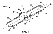
ここで図1−図4を参照すると、例えば内視鏡的処置中などに吻合を形成するための医療装置18の或る実施形態が描かれている。ここで論じられている様に、医療装置18は、吻合の周囲の組織を締め付け、それを開口保持する働きはもとより、吻合の拡大を容易にする働きもする。医療装置18は、概して、水平軸29に沿って互いに反対側に配置されている第1基部20と第2基部22を含んでいる。基部20及び22は、内視鏡の外面に一致するように形状が半円形であるものとして描かれているが、当業者には認識される様に他の形状も適している。基部20及び22は、それぞれ、2つの挿入溝21を有しており、それら挿入溝は、基部20及び22に取り付けられている第1クランプ部材28と第2クランプ部材27が当該挿入溝21の中へ押し込まれることによってそれらクランプ部材をしっかりと受け入れるサイズである。挿入溝21は図4に更に詳しく描かれているが、クランプ部材28と27を挿入溝21に「スナップ嵌め」できるように1つ又はそれ以上の突出部21aによって形成されているのが好適とされる狭い喉部Tを含んでいる。クランプ部材はまた、基部20及び22の中へ包み込まれるなどして基部に永久的に取り付けられていてもよいし、或いは蝶番又は本技術で知られている他の締結装置を介して基部に付着していてもよい。
1-4, one embodiment of a
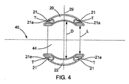
基部20は、基部22とは反対側に、基部20及び22を内視鏡の様な細長い部材に上から嵌められるように設計されている内部空間44を画定するべく距離Lを空けて、配置されている。距離Lは好適には約7mmから約20mmの範囲である。内部空間の直径Dは約8mmから約23mmの範囲とすることができる。ここで使用されている寸法と範囲は、概ね、内視鏡及び胃腸に用いる場合であるが、当業者には他の用途のためのサイズが容易に見極められることであろう。基部は、金属、合金、プラスチック、生体適合性材料、分解吸収性材料、分解性材料、又は如何なる他の適した材料から作られていてもよい。分解吸収性とは、ここでの使用に際しては、材料の組織及び/又は体液に接触したときに当該組織及び/又は体液の中へ吸収されてゆく材料特性をいう。本技術分野では、数多くの分解吸収性材料が知られており、如何なる適した分解吸収性材料が使用されてもよい。例として、分解吸収性のホモポリマー、コポリマー、又は分解吸収性ポリマーの配合物が挙げられる。分解性とは、ここでの使用に際しては、材料の体内に植え込まれたときに臨床上妥当な時間量の内に放散してゆく特性であって、溶解、崩解、吸収、及び排泄の様な放散を起こすことのできるメカニズムとは無関係に放散することができる特性をいい、基部20及び22は、クランプ部材28及び27から係合解除されるように分解しさえすれば十分である。数多くの分解性材料が当技術分野で知られており、如何なる適した分解性材料が使用されてもよい。例として、ポリエチレン、ポリプロピレン、及びポリオキシプロピレングリコール系糖類並びにポリラクチド系糖類が挙げられる。
The
図1−図3Aから最もよく分かる様に、第1クランプ部材28は、近位部分24、中間部分19、及び遠位部分26を有している。図3Aは、未だ取り付けられていない、その自然な状態にある第1クランプ部材28を示している。近位部分24と遠位部分26はともに、それらが図1に示されている様につがうことができるように共通の形状とデザインを有している。描かれている様に、近位部分24と遠位部分26は概ねU字形状を有しているが、それらは、V字形状、半矩形の形状、又は如何なる他の半環状形状とすることもできる。クランプ部材28及び27は、内部空間44と連通、好適には連続する、内部空間71を画定する形状を有している。近位部分24と遠位部分26は、それらが基部20及び22の挿入溝21に取り付けられている中間部分19周りに回転させることができる。同様に、第2クランプ部材27は、基部20及び22の挿入溝21に取り付けられている中間部分19周りに回転させることができる近位部分23と遠位部分25を有している。
As best seen in FIGS. 1-3A, the first clamping
図1及び図3Aでは、クランプ部材28と27は、近位部分24及び23が遠位部分26及び25に対して略平行になるように回転して、その結果クランプ部材28と27が横方向に横軸40(基部20と22も当該横軸周りに離間されている)に沿って突き出る格好になっている配備状態にある。略平行とは、ここでの使用に際しては、組織が近位部分24及び23と遠位部分26及び25との間で締め付けられことが可能である限りにおいては、近位部分24及び23と遠位部分26及び25との間の平行からの偏差を含んでいる。配備状態は、近位部分24及び23と遠位部分26及び25が図3Aに見られる様に中間部分19に概ね垂直になるように回転した状態と言うこともできる。配備状態では、近位部分24及び23は、図7に示され以下に更に詳細に説明されている様に、遠位部分26及び25との間の組織を締め付けるために遠位部分26及び25に向けて回転する。
1 and 3A, the
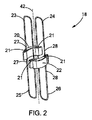
図2では、医療装置18のクランプ部材28及び27は、長手方向軸42に向けて回転して、クランプ部材28と27の近位部分24と23が互いに隣接し、クランプ部材28と27の遠位部分26と25が互いに隣接している送達状態にある。近位部分24及び23と遠位部分26及び25は、クランプ部材28と27が長手方向軸42に沿って整列して互いに略平行になるように回転しているのが好適である。
In FIG. 2, the
図1−図3Aに示されている実施形態では、クランプ部材は図3Aに描かれている配備状態の形成に向けて付勢される。クランプ部材28及び27は、丸又は矩形(平)断面形状を有する金属ワイヤ、好適にはニチノール、で形成されているものとして示されているが、他の構成が採用されてもよい。例えば、クランプ部材28及び27は、適した弾性を有していて、それによりクランプ部材が本来備わっているか又は付与された形状記憶特性に従って回転することのできる、他の金属、合金、プラスチック、又は他の材料で構成されていてもよい。クランプ部材28及び27は生体適合性又は分解吸収性の材料で構成されていてもよい。
In the embodiment shown in FIGS. 1-3A, the clamping member is biased towards the formation of the deployed state depicted in FIG. 3A.
加えて、クランプ部材は、本技術で知られている他の締結装置によって基部に取り付けられていてもよいし、蝶番、ばね、又は本技術で知られている他の回転式連結器によって基部に取り付けられていてもよい。例えば、クランプ部材が拘束されていないとき、蝶番を付勢してクランプ部材を配備状態に回転させるようにしてもよいであろう。また、クランプ部材28及び27は、図1−図3Aでは2つの一体のクランプ部材として描かれているが、それぞれは、図3Bに示されている様に2本のワイヤの様な2つの部分から編成されていてもよい。1つの実施形態では、近位部分24は1本のワイヤが基部20と22の両方に取り付けられて構成され、遠位部分26は1本のワイヤが基部20と22の両方に取り付けられて構成され、そうして接続用の中間区間19がないものになっている。蝶番(図示せず)は、近位部分24を遠位部分26に向けて、それぞれが基部から離れるように横方向に突き出る配備状態に回転させることになる。また更には、各近位部分24と各遠位部分26は、ほぼ連続的な近位部分24とほぼ連続的な遠位部分26を形成するように互いに隣接する自由端を有する2つの部分(例えばワイヤ)から編成されていてもよく、その場合、クランプ部材は4つの回転式部品(図示せず)から編成される。
In addition, the clamp member may be attached to the base by other fastening devices known in the art, or may be attached to the base by a hinge, spring, or other rotary coupler known in the art. It may be attached. For example, when the clamp member is not constrained, the hinge may be biased to rotate the clamp member into the deployed state. Also, the
次に吻合を形成するための医療システム70を図5−図9を参照しながら説明していく。医療システム70は、吻合を形成、作成、及び維持するための医療装置と、医療装置を送達するための細長い部材と、医療装置を細長い部材上に保持するための保定装置と、随意ではあるが医療装置を細長い部材から射出するための追加の押出装置と、を含んでいる。図5Aに示されている1つの実施形態によれば、医療装置18は、細長い部材、この事例では内視鏡60、の上へ装填されていることが示されている。内視鏡60は本技術分野で知られている如何なる型式のスコープであってもよいし、又は代わりに、治療目的で身体の中へ挿入されるのに適した如何なる可撓性の細長部材であってもよい。装置18は内視鏡60上をその遠位端43に向かって滑る。クランプ部材の遠位部分26及び25は、第1保定器31を介して送達状態で互いに近接に保持されている。この実施形態では、第1保定器31は、付属チャネル62に通されている縫合糸32であって、縫合糸32はそれぞれの遠位部分26及び25上のループ又はフック30を通過している。縫合糸を遠位部分26と25に巻き付けて、それらを互いに近接に保持するようにしてもよい。縫合糸とは別に、鉗子、把持器、クランプ、又は本技術で知られている類似の装置を付属チャネル62に通し、それらを使用して、遠位部分26と25を互いに近接に保持することもできるであろうし、或いは細長いキャップ、帯、又は本技術で知られている類似の装置を使用して、遠位部分26と25を互いに近接に保持することもできるであろう。
Next, a
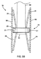
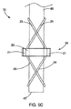
保定器は、更に、近位部分24と23を送達状態に、好適には内視鏡60に沿って互いに略平行に、保持している。この実施形態では、第2保定器33は、近位部分24と23を送達状態に保持しており、第2保定器33は好適には伸縮性の帯34である。第2保定器33は、マルチバンドリゲータと縫合糸、クリップ、ラッチ掛け機構、又は本技術分野で知られている、対象物を送達状態に保定するための他の装置であってもよい。加えて、2つの保定器31及び33を使うのではなく、図5Bに示されているオーバーチューブ66の様な1つの保定器が遠位部分と近位部分の両方を所定場所に引き留めるのに使用されていてもよい。更に、医療装置18は、図5Cに描かれている様に、自らを内視鏡60上に保定するように構成されていてもよく、それにより保定器は必要なくなる。この方式では、クランプ部材28及び27の近位部分24及び23と遠位部分26及び25は、一方の近位部分が他方の近位部分の内部空間71を通り抜け且つ一方の遠位部分が他方の遠位部分の内部空間71を通り抜けた状態でクランプ部材の近位部分24及び23と遠位部分26及び25が全て長手方向軸42を横切るように、長手方向に回転させられることになろう。医療装置18はこうして内視鏡60上に嵌って、クランプ部材の本来備わっている配備状態に復帰する付勢力によってクランプ部材が内視鏡に力を働かせ、医療装置18の内視鏡60上の位置を維持しようとする。
The retainer further holds the
次に図6を参照すると、医療装置18は、遠位方向に、第1の体壁46(例えば胃45)を貫き、第2の体壁48(例えば小腸、典型的には空腸52)を貫いて挿入され、空腸52の内部に置かれている。この実施形態では、縫合糸32は臨床医によって後退させられるか又は切断してから後退させられるかしていて、クランプ部材28及び27の遠位部分26及び25はそれらの配備状態へ回転できるようにされている。システム70を近位方向に引き戻す(即ち、後退させる)と、遠位部分26及び25が第2の体壁48の内面に圧力を働かせる。
Referring now to FIG. 6, the
次に図7を参照すると、内視鏡60は更に後退させられており、ようやく基部が少なくとも部分的に第1の体壁46の小孔49内側にあるのが見えたところで、伸縮性の帯34が解放され、近位部分24及び23がそれらの配備状態へ回転して、第1の体壁46の近位側を押し付け、圧力を働かせられるようになる。近位部分24及び23を解放するための手順は、使用されている保定装置に応じて異なる。図6に描かれている様に第2保定器33が伸縮性の帯34である場合は、第2保定器33は伸縮性の帯34を切除さえすれば取り除くことができる。内視鏡60は代わりに溝か筋が付けられて、内視鏡60を後退させると(例えば筋との摩擦により)伸縮性の帯34が係合するようにされていてもよく、そうすると内視鏡を後退させてゆけば伸縮性の帯34が、好適には内視鏡60上に固定されたままに、近位方向に転がされるか又は動かされるかして近位部分24及び23から離れることができる。また、縫合糸を、内視鏡60の外側を走らせて第2保定器33に結わえておき、縫合糸を引っ張ると第2保定器33が取り除かれるようにしてもよい。また更に、図5Bに描かれている様にオーバーチューブ66が医療装置18全体を覆うように使用されている場合、オーバーチューブ66を後退させると、まず遠位部分がそれらの配備状態へと解放され、オーバーチューブ66を更に後退させてゆくと次に近位部分がそれらの配備状態へと解放されることになる。オーバーチューブ66はそのルーメンの中にスコープ及び器械を受け入れるサイズである。当業者には他の保定装置及びそれらを取り除くための他の手段が認知されることであろう。
Referring now to FIG. 7, the
吻合を形成するための医療方法を、これより図5−図9を参照しながら説明してゆく。吻合を形成するために医療装置18を完全に配備する前に、所望の臓器に小孔を形成しなくてはならず、それらの小孔同士を互いの近傍内に寄せなくてはならない。この目標を達成するための1つのやり方は、図5A、図5B、又は図5Cに描かれている様に医療装置18を内視鏡60上に装填し、次いで内視鏡を第1の臓器まで前進させることである。切断装置(図示せず)を内視鏡60の作業ルーメンを通して前進させ、それを使用して第1の臓器である例えば胃45に小孔49を形成する。次いで内視鏡60を空腸52の様な第2の臓器へ更に前進させ、切断装置を使用して第2の臓器に第2の小孔51を形成する。医療装置18の遠位部分26及び25が上述の様に配備されたなら、次いで、医療装置18、内視鏡60、及び空腸52を、第1の臓器の小孔49に向けて後退させる。医療装置18が図6にあるように正しく位置付けられてしまえば、近位部分24及び23を解放することができ、そうして吻合が形成されることになる。
A medical method for forming an anastomosis will now be described with reference to FIGS. Before the
小孔は、医療装置18の挿入に先立って、形成され、互いに近接に寄せてこられてもよい。これを実現するためのやり方で、本技術で知られているものは数多くあり、そのうちの幾つかは、2008年2月5日出願の米国非仮特許出願第12/025,985号に記載されており、同出願をここに参考文献としてそっくりそのまま援用する。腹腔鏡的手術又は開放性手術及びそれらの手術型式で使用される装置も同様に、医療装置18の挿入を準備するために小孔を形成し、それら小孔を互いに近接に所定場所に保持するのに採用することができる。
The stoma may be formed and brought in close proximity to one another prior to insertion of the
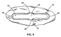
小孔が形成され、以上に説明され図5−図7に描かれているシステム70を介して医療装置18が配備されてしまえば、近位部分24及び23が第1の体壁46に対して働かせている力と、遠位部分26及び25が第2の体壁48に働かせている力が、2つの体壁を圧縮し、それらを互いに近接に保持する。第1基部20と第2基部22は、第1の体壁46の小孔49と第2の体壁48の第2の小孔51を維持する。こうして、システムは即座に、十分なサイズの吻合を形成する。クランプ部材が体壁に働かせている圧縮はクランプ部材の間に閉じ込められている2つの臓器の組織の壊死を引き起こし、その結果、組織の厚さ及びクランプ部材に使用されている材料の強さにもよるが、数日若しくは1週間後には吻合は更に大きくなっている。より大きな吻合が直ぐさま所望されるなら、メス又は他の切断装置を使用して、内部24から横方向に第1クランプ部材28の頂点に向かって切ることによって組織を2つの体壁から切除すれば、図9に描かれている様により大きな開口部72が形成される。追加的に、第2のより大きな開口部72を形成するために、次いで、切開を内部24から横方向に第2クランプ部材27の頂点に向けて延ばしていってもよく、そうすれば今度は1つの大きな途切れのない吻合が形成される。
Once the stoma has been formed and the
医療装置18の除去は自然的な手段を通して完遂されてもよい。組織46及び48に働いている圧力は何日もかけて壊死を引き起こし、それにより24又は24と72を合わせたものより僅かに大きい吻合が形成される。或る一定量の壊死が起こった後、医療装置18は、押し出され、自然に身体を通過してゆくであろう。或いは、医療装置18を分解性又は分解吸収性の材料で作って、装置が身体によって自然に崩壊してゆくようにしてもよい。加えて、基部20及び22を分解性又は分解吸収性の材料で作って、基部が身体によって自然に崩壊してゆくようにしてもよく、それによって、次にクランプ部材27及び28が、仮にそれらが崩壊され得ない場合には、自然に身体を通過してゆくであろう。
Removal of the
当業者には、これらの吻合形成処置の間、組織46及び48の圧縮されている区域は、GI内容物の漏出又は関与している臓器によっては他の体液の漏出を防ぐ障壁を提供していることが認識されるであろう。同様に、吻合は、確実性を以って、患者が医療施設を去る前に形成されるので、フォローアップ処置の必要性はなくなる。また、基部20及び22は―また切開が入れられた場合には同様にクランプ部材28及び27が―吻合のサイズを維持するので、開口部を維持するためにステントを挿入する第2の処置の必要性はない。
For those skilled in the art, during these anastomosis procedures, the compressed area of
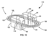
次に図10及び図11を参照すると、吻合を形成するための医療装置118の或る代わりの実施形態が描かれている。医療装置118は、医療装置18の場合とまったく同じ様に、互いに反対側に配置されている第1基部120と第2基部122を含んでいる。基部120及び122は、それぞれ、第1クランプ部材128と第2クランプ部材127を受け入れ案内するための2つのソケット80を有している。この実施形態では、クランプ部材128及び127は、基部120及び122に包み込まれ、それぞれの中間部分119の挿入孔84に通された円筒管82によって所定場所に保持されている。クランプ部材は同様に、蝶番又は本技術で知られている他の締結装置を介して基部120及び122に取り付けられていてもよく、医療装置118には先に医療装置18について論じたものと概ね同様の変更が加えられてもよい。
Referring now to FIGS. 10 and 11, an alternate embodiment of a
第1クランプ部材128は、近位部分124、中間部分119、及び遠位部分126を有しており、第2クランプ部材127は、近位部分123、中間部分119、及び遠位部分125を有している。図10は自然な状態である配備状態にあるクランプ部材128及び127を描いている。近位部分124及び123と遠位部分126及び125は中間部分119周りに回転させることができる。医療装置118の寸法と使用法は医療装置18と概ね同様であり、先の実施形態で既に論じたものと同様の修正がここでも当て嵌まる。
The
図11では、医療装置118のクランプ部材128及び127は、クランプ部材が基部120及び122から離れるように長手方向に回転して、クランプ部材128と127の近位部分124と123が互いに近接し、遠位部分126と125が互いに近接した送達状態にある。基部120及び122のソケット80は、クランプ部材を配備状態から送達状態へ案内しており、医療装置18の28と27では図2に描かれている様に整列できる余地があったが、ソケット80はクランプ部材128と127が長手方向に180度に整列することのないようにしている。示されてはいないが、当業者には、ソケット80及び/又は基部120と122のサイズは、クランプ部材128と127が送達状態で長手方向に180度回転できるように修正されてもよいことが認識されるであろう。
In FIG. 11, the
当業者には認識される様に、以上に記載されている方法は、概して、2つの臓器の体壁を隣接させることを含んでいるが、本システム、装置、及び方法は、人間又は動物の身体に関連し得る材料がそうでないかを問わず、如何なる材料(例えば、織物、布、ポリマー、エラストラマー、プラスチック、及びゴム)の2つの層に使用されてもよいことが認識されるであろう。例えば、本システム、装置及び方法に関しては、研究施設及び産業環境で、人間又は動物の身体への適用が見い出され得る材料かそうでないかを問わず、2層又はそれ以上の材料の層を隣接させる場合の利用、及び同様に、身体組織ではない2層又はそれ以上の材料の層の孔又は穿孔を接続する場合の利用を見い出すことができる。幾つかの例として、縫製又は縫合及び関連の製造工程、合成組織を用いた作業、ポリマーシートの接続又は修復、動物の研究、獣医学的適用、及び死体解剖活動が挙げられる。 As will be appreciated by those skilled in the art, the methods described above generally involve adjoining the body walls of two organs, but the systems, devices, and methods are human or animal. It will be appreciated that any material (eg, woven, cloth, polymer, elastomer, plastic, and rubber) may be used for two layers, whether or not a material that can be related to the body. Let's go. For example, with respect to the present systems, devices and methods, two or more layers of materials are adjacent in research facilities and industrial environments, whether or not materials that can find application to the human or animal body. Uses can be found, as well as use to connect holes or perforations in two or more layers of material that are not body tissue. Some examples include sewing or suturing and related manufacturing processes, working with synthetic tissue, connecting or repairing polymer sheets, animal studies, veterinary applications, and cadaveric activities.
本発明の様々な実施形態を記載してきたが、本発明は、付随の特許請求の範囲及びそれらの等価物に照らした場合を除き限定されるものではない。更に、ここに記載されている利点は必ずしも本発明の唯一の利点というわけではなく、また必ずしも本発明のあらゆる実施形態が、記載されている利点の全てを実現できるものと期待されているわけではない。 While various embodiments of the invention have been described, the invention is not limited except in light of the appended claims and their equivalents. Further, the advantages described herein are not necessarily the only advantages of the present invention, and not every embodiment of the present invention is expected to be able to realize all of the described advantages. Absent.
18 医療装置
19 中間部分
20 第1基部
21 挿入溝
21a 突出部
22 第2基部
23、24 近位部分
25、26 遠位部分
27、28 クランプ部材
29 水平軸
30 ループ又はフック
32 縫合糸
33 第2保定器
34 伸縮性の帯
40 横軸
42 長手方向軸
43 内視鏡の遠位端
44 基部による内部空間
45 胃
46 第1の体壁
48 第2の体壁
49 小孔
51 第2の小孔
52 空腸
60 内視鏡
62 内視鏡の付属チャネル
66 オーバーチューブ
70 医療システム
71 クランプによる内部空間
72 より大きな開口部
80 ソケット
82 円筒管
84 挿入孔
118 医療装置
119 中間部分
120、122 基部
123、124 近位部分
125、126 遠位部分
127、128 クランプ部材
D 内部空間の直径
L 基部間距離
T 基部の挿入溝の喉部
DESCRIPTION OF
Claims (12)
内部空間を画定するように向かい合って配置された第1基部及び第2基部であって、当該第1及び第2基部と前記内部空間とで長手方向軸及び横軸を画定しており、分解性又は分解吸収性の材料からなる、第1基部及び第2基部と、
近位部分と遠位部分を有する第1クランプ部材であって、前記第1及び第2基部に取り付けられ、そこから横方向に延びていて、前記近位部分と前記遠位部分が前記第1及び第2基部に対して回転可能である、分解性でなく且つ分解吸収性でない材料からなる、第1クランプ部材と、
近位部分と遠位部分を有する第2クランプ部材であって、前記第1及び第2基部に取り付けられ、そこから横方向に延びていて、前記近位部分と前記遠位部分が前記第1及び第2基部に対して回転可能である、分解性でなく且つ分解吸収性でない材料からなる、第2クランプ部材と、を備えており、
前記第1クランプ部材と前記第2クランプ部材は、それぞれ、送達状態と配備状態の間で動作可能となっており、前記第1クランプ部材と前記第2クランプ部材は、前記配備状態となるように付勢されており、
前記送達状態となっている前記第1クランプ部材は、前記近位部分と前記遠位部分とが互いから離れる方向に回転されており、前記送達状態の前記第2クランプ部材は、前記近位部分と前記遠位部分とが互いから離れる方向に回転されており、
前記配備状態となっている前記第1クランプ部材は、前記第1クランプ部材の前記近位部分と前記遠位部分とが互いに近接して前記身体組織を間に保持し、前記配備状態となっている前記第2クランプ部材は、前記第2クランプの前記近位部分と前記遠位部分とが互いに近接して前記身体組織を間に保持するようになっている、器械。 An instrument for facilitating the formation of an anastomosis in body tissue,
A first base and a second base arranged to face each other so as to define an internal space, wherein the first and second bases and the internal space define a longitudinal axis and a horizontal axis; Or a first base and a second base made of a decomposition-absorbing material;
A first clamping member having a proximal portion and a distal portion, attached to and extending laterally from the first and second bases, wherein the proximal portion and the distal portion are the first And a first clamping member made of a non-degradable and non-degradable material that is rotatable relative to the second base;
A second clamp member having a proximal portion and a distal portion, attached to and extending laterally from the first and second bases, the proximal portion and the distal portion being the first And a second clamp member that is rotatable relative to the second base and made of a non- degradable and non-degradable material ,
The first clamp member and the second clamp member are operable between a delivery state and a deployed state, respectively, so that the first clamp member and the second clamp member are in the deployed state. Energized,
The first clamp member in the delivery state is rotated in a direction in which the proximal portion and the distal portion are separated from each other, and the second clamp member in the delivery state is the proximal portion And the distal portion are rotated away from each other,
The first clamp member in the deployed state is in the deployed state, with the proximal portion and the distal portion of the first clamp member approaching each other to hold the body tissue therebetween. The second clamping member, wherein the proximal portion and the distal portion of the second clamp are in close proximity to each other to hold the body tissue therebetween.
長手方向軸を画定している細長い部材と、
前記細長い部材から前記器械を射出するための送達部材と、
前記第1及び第2クランプ部材の各遠位部分を前記送達状態に維持し且つ前記第1及び第2クランプ部材の各近位部分を前記送達状態に維持するための少なくとも1つの保定器と、を更に備えており、
前記器械の前記内部空間が、前記細長い部材を受け入れるサイズとなっており、
前記少なくとも1つの保定器が、縫合糸または伸縮性の帯である、医療システム。 A medical system for forming an anastomosis using the instrument of claim 1, comprising:
An elongate member defining a longitudinal axis;
A delivery member for injecting the instrument from the elongate member;
At least one retainer for maintaining the distal portions of the first and second clamp members in the delivery state and maintaining the proximal portions of the first and second clamp members in the delivery state; Is further provided,
The inner space of the instrument is, has a size to receive said elongate member,
The medical system , wherein the at least one retainer is a suture or a stretchable band .
前記第1及び第2基部を、前記第1クランプ部材と前記第2クランプ部材とが前記送達状態に維持された状態で、細長い部材上に嵌める段階と、
前記第1及び第2クランプ部材の各遠位部分を、前記送達状態から、前記第1及び第2クランプ部材の各遠位部分が互いから離れるように横方向に回転している前記配備状態へ回転させる段階と、
前記第1及び第2クランプ部材の各近位部分を、前記送達状態から、前記第1及び第2クランプ部材の各近位部分が互いから離れるように横方向に回転している前記配備状態へ回転させる段階と、を含む前記器械を人間以外の動物の体内に配備する方法。 The first clamp member and the second clamp member are provided with a first base and a second base made of a degradable or decomposable material, to which the first clamp member and the second clamp member are attached. Each having a proximal portion and a distal portion rotatably attached to the first and second bases, wherein the first clamping member and the second clamping member are each of the first clamping member. The proximal portion is substantially parallel to the distal portion of the first clamp member and the proximal portion of the second clamp member is substantially parallel to the distal portion of the second clamp member. The first clamp member and the second clamp member are each rotated longitudinally such that the proximal portion and the distal portion of the first clamp member are spaced apart from each other; Above The proximal portion of the second clamping member and said distal portion has a delivery state of being rotated in the longitudinal direction away from each other, the first clamping member and the second clamping member, respectively, Providing an instrument comprising a non-degradable and non-degradable material ; and
Fitting the first and second bases onto an elongated member with the first clamp member and the second clamp member maintained in the delivery state;
The distal portions of the first and second clamp members are moved from the delivery state to the deployed state in which the distal portions of the first and second clamp members are rotated laterally such that they are separated from each other. Rotating, and
The proximal portions of the first and second clamp members are moved from the delivery state to the deployed state in which the proximal portions of the first and second clamp members are rotated laterally such that they are separated from each other. Rotating the instrument comprising the step of rotating the instrument into a non-human animal body.
Applications Claiming Priority (3)
| Application Number | Priority Date | Filing Date | Title |
|---|---|---|---|
| US22084809P | 2009-06-26 | 2009-06-26 | |
| US61/220,848 | 2009-06-26 | ||
| PCT/US2010/034690 WO2010151382A1 (en) | 2009-06-26 | 2010-05-13 | Linear clamps for anastomosis |
Publications (3)
| Publication Number | Publication Date |
|---|---|
| JP2012531255A JP2012531255A (en) | 2012-12-10 |
| JP2012531255A5 JP2012531255A5 (en) | 2013-06-27 |
| JP5674775B2 true JP5674775B2 (en) | 2015-02-25 |
Family
ID=42352007
Family Applications (1)
| Application Number | Title | Priority Date | Filing Date |
|---|---|---|---|
| JP2012517532A Active JP5674775B2 (en) | 2009-06-26 | 2010-05-13 | Linear clamp for anastomosis |
Country Status (5)
| Country | Link |
|---|---|
| US (1) | US8728103B2 (en) |
| EP (1) | EP2445418B1 (en) |
| JP (1) | JP5674775B2 (en) |
| AU (1) | AU2010263224B2 (en) |
| WO (1) | WO2010151382A1 (en) |
Families Citing this family (23)
| Publication number | Priority date | Publication date | Assignee | Title |
|---|---|---|---|---|
| US10166128B2 (en) | 2011-01-14 | 2019-01-01 | W. L. Gore & Associates. Inc. | Lattice |
| US9839540B2 (en) | 2011-01-14 | 2017-12-12 | W. L. Gore & Associates, Inc. | Stent |
| US9931193B2 (en) | 2012-11-13 | 2018-04-03 | W. L. Gore & Associates, Inc. | Elastic stent graft |
| US9144492B2 (en) | 2012-12-19 | 2015-09-29 | W. L. Gore & Associates, Inc. | Truncated leaflet for prosthetic heart valves, preformed valve |
| US9101469B2 (en) | 2012-12-19 | 2015-08-11 | W. L. Gore & Associates, Inc. | Prosthetic heart valve with leaflet shelving |
| US9968443B2 (en) | 2012-12-19 | 2018-05-15 | W. L. Gore & Associates, Inc. | Vertical coaptation zone in a planar portion of prosthetic heart valve leaflet |
| US9364238B2 (en) * | 2013-04-16 | 2016-06-14 | Ethicon Endo-Surgery, Inc. | Method and apparatus for joining hollow organ sections in anastomosis |
| US11033272B2 (en) | 2013-04-16 | 2021-06-15 | Ethicon Endo-Surgery, Inc. | Methods for partial diversion of the intestinal tract |
| US10842918B2 (en) | 2013-12-05 | 2020-11-24 | W.L. Gore & Associates, Inc. | Length extensible implantable device and methods for making such devices |
| WO2015095333A1 (en) | 2013-12-17 | 2015-06-25 | Standard Bariatrics, Inc. | Resection line guide for a medical procedure and method of using same |
| US9724096B2 (en) | 2014-03-29 | 2017-08-08 | Standard Bariatrics, Inc. | End effectors, surgical stapling devices, and methods of using same |
| US9936953B2 (en) | 2014-03-29 | 2018-04-10 | Standard Bariatrics, Inc. | End effectors, surgical stapling devices, and methods of using same |
| WO2016037158A1 (en) | 2014-09-05 | 2016-03-10 | Standard Bariatrics, Inc. | Sleeve gastrectomy calibration tube and method of using same |
| US9827094B2 (en) | 2014-09-15 | 2017-11-28 | W. L. Gore & Associates, Inc. | Prosthetic heart valve with retention elements |
| US10285837B1 (en) | 2015-09-16 | 2019-05-14 | Standard Bariatrics, Inc. | Systems and methods for measuring volume of potential sleeve in a sleeve gastrectomy |
| EP4233806A3 (en) | 2016-04-21 | 2023-09-06 | W. L. Gore & Associates, Inc. | Diametrically adjustable endoprostheses |
| WO2019036490A1 (en) | 2017-08-14 | 2019-02-21 | Standard Bariatrics, Inc. | End effectors, surgical stapling devices, and methods of using same |
| US11020221B2 (en) | 2017-09-27 | 2021-06-01 | W. L. Gore & Associates, Inc. | Prosthetic valve with expandable frame and associated systems and methods |
| CA3078606C (en) | 2017-10-31 | 2023-09-05 | W.L. Gore & Associates, Inc. | Medical valve and leaflet promoting tissue ingrowth |
| AU2019406218B2 (en) | 2018-12-21 | 2023-03-30 | W. L. Gore & Associates, Inc. | Implantable cardiac sensors |
| US11497601B2 (en) | 2019-03-01 | 2022-11-15 | W. L. Gore & Associates, Inc. | Telescoping prosthetic valve with retention element |
| WO2021101714A1 (en) | 2019-11-04 | 2021-05-27 | Standard Bariatrics, Inc. | Systems and methods of performing surgery using laplace's law tension retraction during surgery |
| US11452574B1 (en) | 2021-03-23 | 2022-09-27 | Standard Bariatrics, Inc. | Systems and methods for preventing tissue migration in surgical staplers |
Family Cites Families (220)
| Publication number | Priority date | Publication date | Assignee | Title |
|---|---|---|---|---|
| US766197A (en) * | 1904-01-19 | 1904-08-02 | Louis M Picker | Display-case. |
| GB877903A (en) | 1958-02-17 | 1961-09-20 | Initial Plastics Ltd | Improvements in paper clips |
| GB1035205A (en) | 1962-11-30 | 1966-07-06 | Yeda Res & Dev | Improvements in the remote controlled propulsion of a body |
| US3299883A (en) | 1963-11-08 | 1967-01-24 | Engelhard Hanovia Inc | Gynecologic instrument |
| SE336642B (en) | 1969-10-28 | 1971-07-12 | Astra Meditec Ab | |
| US3709214A (en) | 1971-10-27 | 1973-01-09 | J Robertson | Gas obturating method |
| US4022208A (en) | 1974-07-25 | 1977-05-10 | Valtchev Konstantin L | Gynecologic instrument |
| US4214587A (en) | 1979-02-12 | 1980-07-29 | Sakura Chester Y Jr | Anastomosis device and method |
| US4899744A (en) | 1988-12-15 | 1990-02-13 | Tatsuo Fujitsuka | Apparatus for anastomosing digestive tract |
| US5081997A (en) | 1989-03-09 | 1992-01-21 | Vance Products Incorporated | Echogenic devices, material and method |
| US5290300A (en) | 1989-07-31 | 1994-03-01 | Baxter International Inc. | Flexible suture guide and holder |
| US5234447A (en) | 1990-08-28 | 1993-08-10 | Robert L. Kaster | Side-to-end vascular anastomotic staple apparatus |
| US5484451A (en) | 1992-05-08 | 1996-01-16 | Ethicon, Inc. | Endoscopic surgical instrument and staples for applying purse string sutures |
| US5766246A (en) | 1992-05-20 | 1998-06-16 | C. R. Bard, Inc. | Implantable prosthesis and method and apparatus for loading and delivering an implantable prothesis |
| GR930100244A (en) | 1992-06-30 | 1994-02-28 | Ethicon Inc | Flexible endoscopic surgical port |
| US5297536A (en) | 1992-08-25 | 1994-03-29 | Wilk Peter J | Method for use in intra-abdominal surgery |
| US5458131A (en) | 1992-08-25 | 1995-10-17 | Wilk; Peter J. | Method for use in intra-abdominal surgery |
| US5578044A (en) | 1992-09-04 | 1996-11-26 | Laurus Medical Corporation | Endoscopic suture system |
| US5304184A (en) | 1992-10-19 | 1994-04-19 | Indiana University Foundation | Apparatus and method for positive closure of an internal tissue membrane opening |
| US5693060A (en) | 1992-11-17 | 1997-12-02 | Smith & Nephew, Inc. | Suture securing device and method |
| US5643317A (en) | 1992-11-25 | 1997-07-01 | William Cook Europe S.A. | Closure prosthesis for transcatheter placement |
| US6355050B1 (en) | 1992-12-10 | 2002-03-12 | Abbott Laboratories | Device and method for suturing tissue |
| US5346501A (en) | 1993-02-05 | 1994-09-13 | Ethicon, Inc. | Laparoscopic absorbable anastomosic fastener and means for applying |
| US5342396A (en) | 1993-03-02 | 1994-08-30 | Cook Melvin S | Staples |
| WO1994023788A1 (en) | 1993-04-20 | 1994-10-27 | Medchem Products, Inc. | Apparatus and method for applying a particulate hemostatic agent to living tissue |
| US5562687A (en) | 1993-07-12 | 1996-10-08 | Mitek Surgical Products, Inc. | Surgical repair kit and its method of use |
| US5527321A (en) | 1993-07-14 | 1996-06-18 | United States Surgical Corporation | Instrument for closing trocar puncture wounds |
| JPH08504120A (en) | 1993-08-25 | 1996-05-07 | アポロ キャメラ,リミテッド ライアビリティー カンパニー | Surgical ligation clip |
| US5584835A (en) | 1993-10-18 | 1996-12-17 | Greenfield; Jon B. | Soft tissue to bone fixation device and method |
| WO1995011630A1 (en) | 1993-10-25 | 1995-05-04 | Children's Medical Center Corporation | Retractable suture needle with self-contained driver |
| AU1011595A (en) | 1994-01-13 | 1995-07-20 | Ethicon Inc. | Spiral surgical tack |
| IT1269443B (en) | 1994-01-19 | 1997-04-01 | Stefano Nazari | VASCULAR PROSTHESIS FOR THE REPLACEMENT OR INTERNAL COATING OF MEDIUM AND LARGE DIAMETER BLOOD VESSELS AND DEVICE FOR ITS APPLICATION WITHOUT INTERRUPTION OF BLOOD FLOW |
| CH687060A5 (en) | 1994-02-11 | 1996-09-13 | Alice Walder Utz Dr | Piece surgical clip. |
| US5429131A (en) | 1994-02-25 | 1995-07-04 | The Regents Of The University Of California | Magnetized electrode tip catheter |
| AT400304B (en) | 1994-02-28 | 1995-12-27 | Immuno Ag | DEVICE FOR APPLICATING A MULTI-COMPONENT TISSUE ADHESIVE |
| GB9405790D0 (en) | 1994-03-23 | 1994-05-11 | Univ London | Sewing device |
| US5562688A (en) | 1994-03-25 | 1996-10-08 | Riza; Erol D. | Apparatus facilitating suturing in laparoscopic surgery |
| US5630824A (en) | 1994-06-01 | 1997-05-20 | Innovasive Devices, Inc. | Suture attachment device |
| US5573540A (en) | 1994-07-18 | 1996-11-12 | Yoon; Inbae | Apparatus and method for suturing an opening in anatomical tissue |
| US5573542A (en) | 1994-08-17 | 1996-11-12 | Tahoe Surgical Instruments-Puerto Rico | Endoscopic suture placement tool |
| US5571090A (en) | 1994-10-07 | 1996-11-05 | United States Surgical Corporation | Vascular suturing apparatus |
| US5938668A (en) | 1994-10-07 | 1999-08-17 | United States Surgical | Surgical suturing apparatus |
| CA2157744C (en) | 1994-10-07 | 2005-08-23 | Charles R. Sherts | Endoscopic vascular suturing apparatus |
| US5643292A (en) | 1995-01-10 | 1997-07-01 | Applied Medical Resources Corporation | Percutaneous suturing device |
| US5645552A (en) | 1995-01-11 | 1997-07-08 | United States Surgical Corporation | Surgical apparatus for suturing body tissue |
| JPH10512470A (en) | 1995-01-18 | 1998-12-02 | メドケム プロダクツ,インコーポレーテッド | Apparatus and method for applying a hemostatic agent to tissue |
| US6110187A (en) | 1995-02-24 | 2000-08-29 | Heartport, Inc. | Device and method for minimizing heart displacements during a beating heart surgical procedure |
| US5904697A (en) | 1995-02-24 | 1999-05-18 | Heartport, Inc. | Devices and methods for performing a vascular anastomosis |
| US5976159A (en) | 1995-02-24 | 1999-11-02 | Heartport, Inc. | Surgical clips and methods for tissue approximation |
| US5919184A (en) | 1995-03-17 | 1999-07-06 | Tilton, Jr.; Eugene B. | Instrumentation for laparoscopic insertion and application of surgical sheet material |
| US6086608A (en) | 1996-02-22 | 2000-07-11 | Smith & Nephew, Inc. | Suture collet |
| US6132438A (en) | 1995-06-07 | 2000-10-17 | Ep Technologies, Inc. | Devices for installing stasis reducing means in body tissue |
| US5690656A (en) | 1995-06-27 | 1997-11-25 | Cook Incorporated | Method and apparatus for creating abdominal visceral anastomoses |
| US5700273A (en) | 1995-07-14 | 1997-12-23 | C.R. Bard, Inc. | Wound closure apparatus and method |
| US5846253A (en) | 1995-07-14 | 1998-12-08 | C. R. Bard, Inc. | Wound closure apparatus and method |
| WO1997007745A1 (en) | 1995-08-24 | 1997-03-06 | Nobles-Lai Engineering, Inc. | Method and apparatus for suturing |
| US5782865A (en) | 1995-08-25 | 1998-07-21 | Grotz; Robert Thomas | Stabilizer for human joints |
| US5653717A (en) | 1995-08-28 | 1997-08-05 | Urohealth Systems, Inc. | Wound closure device |
| US5674231A (en) | 1995-10-20 | 1997-10-07 | United States Surgical Corporation | Apparatus and method for vascular hole closure |
| US5582615A (en) | 1995-10-30 | 1996-12-10 | Pilling Weck, Incorporated | Handle for surgical clip applicator systems |
| CN1218414A (en) * | 1996-02-02 | 1999-06-02 | 血管转换公司 | Methods and apparatus for blocking flow through blood vessels |
| US5759169A (en) | 1996-03-13 | 1998-06-02 | New York Blood Center Inc. | Fibrin sealant glue-gun |
| US5788625A (en) | 1996-04-05 | 1998-08-04 | Depuy Orthopaedics, Inc. | Method of making reconstructive SIS structure for cartilaginous elements in situ |
| US5824010A (en) | 1996-05-23 | 1998-10-20 | Mcdonald; Garth R. | Suture needle guide |
| US5810848A (en) | 1996-08-21 | 1998-09-22 | Hayhurst; John O. | Suturing system |
| US6811555B1 (en) * | 1996-09-16 | 2004-11-02 | Origin Medsystems, Inc. | Method and apparatus for performing anastomosis with eversion of tissue edges and joining of exposed intima of the everted tissue |
| US5868763A (en) | 1996-09-16 | 1999-02-09 | Guidant Corporation | Means and methods for performing an anastomosis |
| US5865836A (en) | 1996-09-20 | 1999-02-02 | United States Surgical Corporation | Needle-suture combination |
| US5948000A (en) | 1996-10-03 | 1999-09-07 | United States Surgical Corporation | System for suture anchor placement |
| US5902228A (en) | 1996-10-11 | 1999-05-11 | Cornell Research Foundation, Inc. | Method and apparatus for support and tubularization of surgical grafts |
| CA2224366C (en) | 1996-12-11 | 2006-10-31 | Ethicon, Inc. | Meniscal repair device |
| US6149658A (en) | 1997-01-09 | 2000-11-21 | Coalescent Surgical, Inc. | Sutured staple surgical fasteners, instruments and methods for minimally invasive vascular and endoscopic surgery |
| DE19704211B4 (en) | 1997-02-05 | 2009-06-18 | Schulz, Rolf A., Dipl.-Kaufm. | Flat sheet clamp |
| US6331172B1 (en) | 1997-04-14 | 2001-12-18 | Baxter International Inc. | Applicator for dispensing measured quantities with use of controlled suction |
| US5891159A (en) | 1997-05-02 | 1999-04-06 | Cardiothoratic Systems, Inc. | Automatic purse string suture device |
| US5908428A (en) | 1997-05-27 | 1999-06-01 | United States Surgical Corporation | Stitching devices for heart valve replacement surgery |
| US6077217A (en) | 1997-06-25 | 2000-06-20 | Ramus Medical Technologies, Inc. | System and method for assembling graft structures |
| US6293952B1 (en) | 1997-07-31 | 2001-09-25 | Circon Corporation | Medical instrument system for piercing through tissue |
| US6015414A (en) | 1997-08-29 | 2000-01-18 | Stereotaxis, Inc. | Method and apparatus for magnetically controlling motion direction of a mechanically pushed catheter |
| US6021776A (en) | 1997-09-09 | 2000-02-08 | Intertex Research, Inc. | Disposable atomizer device with trigger valve system |
| US5873530A (en) | 1997-09-26 | 1999-02-23 | Chizinsky; George | Liquid atomizing spray gun |
| US5984949A (en) | 1997-10-06 | 1999-11-16 | Levin; John M. | Tissue hooks and tools for applying same |
| JP3342021B2 (en) | 1997-10-17 | 2002-11-05 | サーコン コーポレーション | Medical device system that penetrates tissue |
| US5931844A (en) | 1998-03-31 | 1999-08-03 | Smith & Nephew, Inc. | Surgical drive tool |
| US20040087985A1 (en) | 1999-03-19 | 2004-05-06 | Amir Loshakove | Graft and connector delivery |
| US5972002A (en) | 1998-06-02 | 1999-10-26 | Cabot Technology Corporation | Apparatus and method for surgical ligation |
| US6030365A (en) | 1998-06-10 | 2000-02-29 | Laufer; Michael D. | Minimally invasive sterile surgical access device and method |
| US6200329B1 (en) | 1998-08-31 | 2001-03-13 | Smith & Nephew, Inc. | Suture collet |
| US6152937A (en) | 1998-11-06 | 2000-11-28 | St. Jude Medical Cardiovascular Group, Inc. | Medical graft connector and methods of making and installing same |
| US6113612A (en) | 1998-11-06 | 2000-09-05 | St. Jude Medical Cardiovascular Group, Inc. | Medical anastomosis apparatus |
| US6110183A (en) | 1998-12-22 | 2000-08-29 | Cook Incorporated | Suture anchor device |
| ATE324072T1 (en) | 1998-12-30 | 2006-05-15 | Ethicon Inc | THREAD SECURING DEVICE |
| US6193732B1 (en) | 1999-01-08 | 2001-02-27 | Cardiothoracic System | Surgical clips and apparatus and method for clip placement |
| CA2261488A1 (en) | 1999-01-21 | 2000-07-21 | Anthony Paolitto | Transabdominal device for performing closed-chest cardiac surgery |
| US6159223A (en) | 1999-01-26 | 2000-12-12 | Endoscopic Concepts, Inc. | Surgical clip applicator |
| US7226467B2 (en) | 1999-04-09 | 2007-06-05 | Evalve, Inc. | Fixation device delivery catheter, systems and methods of use |
| US6569173B1 (en) | 1999-12-14 | 2003-05-27 | Integrated Vascular Interventional Technologies, L.C. | Compression plate anastomosis apparatus |
| US6428550B1 (en) | 1999-05-18 | 2002-08-06 | Cardica, Inc. | Sutureless closure and deployment system for connecting blood vessels |
| US6251116B1 (en) * | 1999-07-28 | 2001-06-26 | Vasconnect, Inc. | Device for interconnecting vessels in a patient |
| JP4108882B2 (en) | 1999-08-04 | 2008-06-25 | オリンパス株式会社 | Endoscope wall fixture |
| JP3901421B2 (en) | 1999-08-19 | 2007-04-04 | 有限会社 パックス オプティカ ジャパン | Organ anastomosis device |
| US6494889B1 (en) | 1999-09-01 | 2002-12-17 | Converge Medical, Inc. | Additional sutureless anastomosis embodiments |
| US6231561B1 (en) | 1999-09-20 | 2001-05-15 | Appriva Medical, Inc. | Method and apparatus for closing a body lumen |
| US6689062B1 (en) | 1999-11-23 | 2004-02-10 | Microaccess Medical Systems, Inc. | Method and apparatus for transesophageal cardiovascular procedures |
| US6527753B2 (en) | 2000-02-29 | 2003-03-04 | Olympus Optical Co., Ltd. | Endoscopic treatment system |
| AU2001249308A1 (en) | 2000-03-24 | 2001-10-15 | Johns Hopkins University | Peritoneal cavity device and method |
| IL136702A (en) | 2000-06-12 | 2005-11-20 | Niti Alloys Tech Ltd | Surgical clip |
| US6572629B2 (en) | 2000-08-17 | 2003-06-03 | Johns Hopkins University | Gastric reduction endoscopy |
| CA2423061A1 (en) | 2000-09-25 | 2002-03-28 | Cohesion Technologies, Inc. | Resorbable anastomosis stents and plugs |
| US6535764B2 (en) | 2001-05-01 | 2003-03-18 | Intrapace, Inc. | Gastric treatment and diagnosis device and method |
| US20060293701A1 (en) | 2001-05-02 | 2006-12-28 | Medtronic, Inc. | Self-closing surgical clip for tissue |
| US7115136B2 (en) | 2001-06-20 | 2006-10-03 | Park Medical Llc | Anastomotic device |
| US6629988B2 (en) * | 2001-08-28 | 2003-10-07 | Ethicon, Inc. | Composite staple for completing an anastomosis |
| US7892247B2 (en) * | 2001-10-03 | 2011-02-22 | Bioconnect Systems, Inc. | Devices and methods for interconnecting vessels |
| US7637919B2 (en) | 2002-01-30 | 2009-12-29 | Olympus Corporation | Anastomosis system for performing anastomosis in body |
| JP4351458B2 (en) | 2002-03-18 | 2009-10-28 | オリンパス株式会社 | Endoscope insertion system |
| JP4405165B2 (en) | 2002-03-19 | 2010-01-27 | オリンパス株式会社 | Endoscope system |
| JP3930757B2 (en) | 2002-04-10 | 2007-06-13 | 有限会社 パックス オプティカ ジャパン | Organ anastomosis device |
| US7648515B2 (en) | 2002-04-16 | 2010-01-19 | Tyco Healthcare Group Lp | Method and apparatus for anastomosis including an expandable anchor |
| US6837847B2 (en) | 2002-06-13 | 2005-01-04 | Usgi Medical, Inc. | Shape lockable apparatus and method for advancing an instrument through unsupported anatomy |
| JP4384033B2 (en) | 2002-06-19 | 2009-12-16 | タイコ ヘルスケア グループ エルピー | Method and apparatus for anastomosis |
| US8066724B2 (en) | 2002-09-12 | 2011-11-29 | Medtronic, Inc. | Anastomosis apparatus and methods |
| US20060025788A1 (en) | 2002-09-25 | 2006-02-02 | By-Pass, Inc. | Anastomotic leg arrangement |
| US8105345B2 (en) | 2002-10-04 | 2012-01-31 | Medtronic, Inc. | Anastomosis apparatus and methods |
| US7351202B2 (en) | 2002-12-05 | 2008-04-01 | Ethicon Endo-Surgery, Inc. | Medical device with track and method of use |
| US20040186349A1 (en) | 2002-12-24 | 2004-09-23 | Usgi Medical Corp. | Apparatus and methods for achieving endoluminal access |
| US20040249367A1 (en) | 2003-01-15 | 2004-12-09 | Usgi Medical Corp. | Endoluminal tool deployment system |
| DE602004015729D1 (en) | 2003-02-11 | 2008-09-25 | Olympus Corp | ABOUT TUBE |
| JP4477382B2 (en) | 2003-03-04 | 2010-06-09 | オリンパス株式会社 | Endoscopic intraperitoneal treatment system |
| GB0307826D0 (en) | 2003-04-04 | 2003-05-07 | Univ London | A device for transfixing and joining tissue |
| US7621924B2 (en) | 2003-04-16 | 2009-11-24 | Tyco Healthcare Group Lp | Method and apparatus for radical prostatectomy anastomosis including an anchor for engaging a body vessel and deployable sutures |
| US7615005B2 (en) | 2003-05-16 | 2009-11-10 | Ethicon Endo-Surgery, Inc. | Medical apparatus for use with an endoscope |
| JP4145200B2 (en) | 2003-06-06 | 2008-09-03 | オリンパス株式会社 | Suture device |
| US6918871B2 (en) | 2003-06-19 | 2005-07-19 | Ethicon Endo-Surgery, Inc. | Method for accessing cavity |
| US7608086B2 (en) | 2003-09-30 | 2009-10-27 | Ethicon Endo-Surgery, Inc. | Anastomosis wire ring device |
| US20050070935A1 (en) * | 2003-09-30 | 2005-03-31 | Ortiz Mark S. | Single lumen access deployable ring for intralumenal anastomosis |
| WO2005053511A2 (en) | 2003-11-26 | 2005-06-16 | Johns Hopkins University | Peroral transgastric endoscopic techniques |
| US7618427B2 (en) | 2003-12-29 | 2009-11-17 | Ethicon Endo-Surgery, Inc. | Device and method for intralumenal anastomosis |
| EP1713402B1 (en) | 2004-02-13 | 2018-07-04 | Ethicon Endo-Surgery, Inc. | Device for reducing stomach volume |
| US7553317B2 (en) | 2004-05-07 | 2009-06-30 | Ethicon Endo-Surgery, Inc. | Instrument for effecting anastomosis of respective tissues defining two body lumens |
| US8206417B2 (en) | 2004-06-09 | 2012-06-26 | Usgi Medical Inc. | Apparatus and methods for optimizing anchoring force |
| EP1765451B1 (en) | 2004-06-14 | 2021-11-17 | Edwards Lifesciences Corporation | Devices for arterio-venous fistula creation |
| US7232448B2 (en) | 2004-06-17 | 2007-06-19 | Ethicon, Inc. - Usa | Minimally invasive stitching device |
| US20060036267A1 (en) | 2004-08-11 | 2006-02-16 | Usgi Medical Inc. | Methods and apparatus for performing malabsorptive bypass procedures within a patient's gastro-intestinal lumen |
| US7828814B2 (en) * | 2004-08-27 | 2010-11-09 | Rox Medical, Inc. | Device and method for establishing an artificial arterio-venous fistula |
| US9706997B2 (en) | 2004-08-27 | 2017-07-18 | Rox Medical, Inc. | Device and method for establishing an artificial arterio-venous fistula |
| WO2006081134A2 (en) | 2005-01-26 | 2006-08-03 | Wilk Patent, Llc | Intra-abdominal medical procedures and device |
| US7766810B2 (en) | 2005-03-10 | 2010-08-03 | Olympus Medical Systems Corp. | Probing method and holding method for luminal organ |
| US20060211919A1 (en) | 2005-03-18 | 2006-09-21 | Wilk Patent. Llc | Intra-abdominal medical device and associated method |
| US20060212063A1 (en) | 2005-03-18 | 2006-09-21 | Wilk Patent, Llc | Surgical device and associated trans-organ surgical method |
| US7789890B2 (en) | 2005-03-30 | 2010-09-07 | Ethicon Endo-Surgery, Inc. | Harness and balloon catheter assembly and method for use in anastomosis procedures |
| US20060258909A1 (en) | 2005-04-08 | 2006-11-16 | Usgi Medical, Inc. | Methods and apparatus for maintaining sterility during transluminal procedures |
| US20060241480A1 (en) | 2005-04-12 | 2006-10-26 | Wilk Patent, Llc | Endoscopic medical method and associated device |
| US7963941B2 (en) | 2005-04-12 | 2011-06-21 | Wilk Peter J | Intra-abdominal medical method and associated device |
| US20060241344A1 (en) | 2005-04-12 | 2006-10-26 | Wilk Patent, Llc | Intra-abdominal surgical method and associated apparatus |
| US20060241691A1 (en) | 2005-04-12 | 2006-10-26 | Wilk Patent, Llc | Medical treatment method and device utilizing magnetic elements |
| US20060241651A1 (en) | 2005-04-22 | 2006-10-26 | Wilk Patent, Llc | Surgical port device and associated method |
| US7785251B2 (en) | 2005-04-22 | 2010-08-31 | Wilk Patent, Llc | Port extraction method for trans-organ surgery |
| US20060241570A1 (en) | 2005-04-22 | 2006-10-26 | Wilk Patent, Llc | Intra-abdominal medical method |
| US20060252997A1 (en) | 2005-04-22 | 2006-11-09 | Wilk Patent, Llc | Medical port device, kit and associated method |
| US20060237023A1 (en) | 2005-04-26 | 2006-10-26 | Usgi Medical Inc. | Transgastric tubal ligation |
| US8663236B2 (en) | 2005-04-26 | 2014-03-04 | Usgi Medical Inc. | Transgastric abdominal access |
| US20100106171A1 (en) * | 2005-05-06 | 2010-04-29 | Johns Hopkins University | Transcaval mesenteric venous anastomosis and access system |
| US20060287666A1 (en) | 2005-06-15 | 2006-12-21 | Usgi Medical Inc. | Apparatus and methods for endoluminal advancement |
| US7591828B2 (en) | 2005-07-22 | 2009-09-22 | Ethicon Endo-Surgery, Inc. | Resposable anastomotic ring applier device |
| US20100114124A1 (en) | 2005-08-03 | 2010-05-06 | Brian Kelleher | Method and apparatus for partioning an organ within the body |
| US8021355B2 (en) | 2005-08-12 | 2011-09-20 | Board Of Regents The University Of Texas System | System, kit, and method of transgastric removal of visceral fat and other related methods |
| US20070123840A1 (en) | 2005-10-18 | 2007-05-31 | Usgi Medical, Inc. | Instrument assisted abdominal access |
| US20070112362A1 (en) | 2005-11-14 | 2007-05-17 | Olympus Medical Systems Corp. | Perforation suturing method |
| US20080312502A1 (en) | 2005-12-02 | 2008-12-18 | Christopher Paul Swain | System and Device for in Vivo Procedures |
| US9962066B2 (en) | 2005-12-30 | 2018-05-08 | Intuitive Surgical Operations, Inc. | Methods and apparatus to shape flexible entry guides for minimally invasive surgery |
| TW200744518A (en) | 2006-01-06 | 2007-12-16 | Olympus Medical Systems Corp | Medical system conducted percutaneous or using naturally ocurring body orifice |
| US20070260214A1 (en) | 2006-01-13 | 2007-11-08 | Olympus Medical Systems Corp. | Medical procedure through natural body opening |
| US7785333B2 (en) | 2006-02-21 | 2010-08-31 | Olympus Medical Systems Corp. | Overtube and operative procedure via bodily orifice |
| US20070167675A1 (en) | 2006-01-13 | 2007-07-19 | Olympus Medical Systems Corp. | Overtube and medical procedure via natural orifice using the same |
| US7735489B2 (en) | 2006-01-13 | 2010-06-15 | Olympus Medical Systems Corp. | Endotracheal tube, device for use in medical procedure through natural opening and medical procedure through natural opening |
| WO2007080971A1 (en) | 2006-01-13 | 2007-07-19 | Olympus Medical Systems Corp. | Overtube for endoscope |
| US20070167676A1 (en) | 2006-01-13 | 2007-07-19 | Olympus Medical Systems Corp. | Overtube and medical procedure via natural orifice using the same |
| US20070219411A1 (en) | 2006-01-13 | 2007-09-20 | Olympus Medical Systems Corp. | Overtube and endoscopic treatment system |
| US20070163604A1 (en) | 2006-01-13 | 2007-07-19 | Olympus Medical Systems Corp. | Leak test method for medical procedure via natural orifice |
| US20070163585A1 (en) | 2006-01-13 | 2007-07-19 | Olympus Medical Systems Corp. | Method for accessing abdominal cavity and medical procedure via natural orifice |
| US20070167967A1 (en) | 2006-01-13 | 2007-07-19 | Olympus Medical Systems Corp. | Medical procedure via natural orifice and puncture device |
| US8241279B2 (en) | 2006-02-23 | 2012-08-14 | Olympus Medical Systems Corp. | Overtube and natural opening medical procedures using the same |
| US8002695B2 (en) | 2006-01-13 | 2011-08-23 | Olympus Medical Systems Corp. | Medical procedure via natural opening |
| US20070213702A1 (en) | 2006-03-08 | 2007-09-13 | Olympus Medical Systems Corp. | Medical procedure carried out via a natural opening |
| US20070213749A1 (en) | 2006-03-08 | 2007-09-13 | Olympus Medical Systems Corp. | Medical procedure performed inside abdominal cavity |
| US20070225734A1 (en) | 2006-03-22 | 2007-09-27 | Minos Medical | Systems and methods for less invasive resolution of maladies of tissue including the appendix, gall bladder, and hemorrhoids |
| US8406901B2 (en) * | 2006-04-27 | 2013-03-26 | Medtronic, Inc. | Sutureless implantable medical device fixation |
| EP2012697A4 (en) | 2006-04-29 | 2010-07-21 | Univ Texas | Devices for use in transluminal and endoluminal surgery |
| US20070270629A1 (en) | 2006-05-19 | 2007-11-22 | Charles Filipi J | System and techniques for magnetic manipulation of internal organs during minimally invasive surgery |
| US9549663B2 (en) | 2006-06-13 | 2017-01-24 | Intuitive Surgical Operations, Inc. | Teleoperated surgical retractor system |
| US7815566B2 (en) | 2006-07-20 | 2010-10-19 | Ethicon Endo-Surgery, Inc. | Methods for stabilizing and positioning an endoscope and surgical procedures |
| US20080051626A1 (en) | 2006-08-28 | 2008-02-28 | Olympus Medical Systems Corp. | Fistulectomy method between first duct and second duct, ultrasonic endoscope, catheter with balloon, magnet retaining device, and magnet set |
| US8475453B2 (en) | 2006-10-06 | 2013-07-02 | Covidien Lp | Endoscopic vessel sealer and divider having a flexible articulating shaft |
| JP4584230B2 (en) | 2006-11-14 | 2010-11-17 | オリンパスメディカルシステムズ株式会社 | Clip device |
| US8221443B2 (en) | 2006-11-15 | 2012-07-17 | Mayo Foundation For Medical Education And Research | Submucosal endoscopy with mucosal flap methods and kits |
| US8025670B2 (en) | 2006-11-22 | 2011-09-27 | Minos Medical | Methods and apparatus for natural orifice vaginal hysterectomy |
| JP2008161570A (en) | 2006-12-28 | 2008-07-17 | Olympus Medical Systems Corp | Ultrasonic endoscope system |
| US20080171907A1 (en) | 2007-01-12 | 2008-07-17 | Ethicon Endo-Surgery, Inc. | Magnetic Tissue Grasping |
| US20080183039A1 (en) | 2007-01-26 | 2008-07-31 | Ethicon Endo-Surgery, Inc. | Balloon Positioning System for Endoscopic Access |
| US20080200762A1 (en) | 2007-02-16 | 2008-08-21 | Stokes Michael J | Flexible endoscope shapelock |
| US8460314B2 (en) | 2007-02-26 | 2013-06-11 | Olympus Medical Systems Corp. | Application of procedure through natural orifice |
| US8155728B2 (en) | 2007-08-22 | 2012-04-10 | Ethicon Endo-Surgery, Inc. | Medical system, method, and storage medium concerning a natural orifice transluminal medical procedure |
| US20080228203A1 (en) | 2007-03-15 | 2008-09-18 | Minos Medical | System and method for translumenal closure in natural orifice surgery |
| JP4996311B2 (en) | 2007-04-05 | 2012-08-08 | オリンパスメディカルシステムズ株式会社 | Treatment instrument system |
| US7967741B2 (en) | 2007-05-01 | 2011-06-28 | Ethicon Endo-Surgery, Inc. | Endoscopic guide device |
| US20090023985A1 (en) | 2007-06-14 | 2009-01-22 | Usgi Medical, Inc. | Endoluminal instrument management system |
| US20090054728A1 (en) | 2007-08-21 | 2009-02-26 | Trusty Robert M | Manipulatable guide system and methods for natural orifice translumenal endoscopic surgery |
| JP2009072368A (en) | 2007-09-20 | 2009-04-09 | Olympus Medical Systems Corp | Medical apparatus |
| US20090182195A1 (en) | 2008-01-11 | 2009-07-16 | Ethicon Endo-Surgery, Inc. | Endoscopic guide system |
| US8792966B2 (en) | 2008-03-03 | 2014-07-29 | Ethicon Endo-Surgery, Inc. | Transluminal tissue markers |
| US8262680B2 (en) | 2008-03-10 | 2012-09-11 | Ethicon Endo-Surgery, Inc. | Anastomotic device |
| US20090254105A1 (en) * | 2008-04-04 | 2009-10-08 | Medtronic Vascular, Inc. | Anastomotic connectors |
| US10350050B2 (en) | 2008-05-01 | 2019-07-16 | Ethicon Endo-Surgery, Inc. | Method for gastric volume reduction surgery |
| US20090281559A1 (en) | 2008-05-06 | 2009-11-12 | Ethicon Endo-Surgery, Inc. | Anastomosis patch |
| US20100010520A1 (en) | 2008-07-11 | 2010-01-14 | Olympus Medical Systems Corp. | Tissue fastener |
| US8685046B2 (en) | 2008-08-05 | 2014-04-01 | Covidien Lp | Magnetic compression anastomosis device |
| US8241204B2 (en) | 2008-08-29 | 2012-08-14 | Ethicon Endo-Surgery, Inc. | Articulating end cap |
| US8425406B2 (en) | 2008-12-19 | 2013-04-23 | Boston Scientific Scimed, Inc. | Systems and methods for directing instruments to varying positions at the distal end of a guide tube |
| US8828031B2 (en) | 2009-01-12 | 2014-09-09 | Ethicon Endo-Surgery, Inc. | Apparatus for forming an anastomosis |
-
2010
- 2010-05-13 EP EP10719705.5A patent/EP2445418B1/en active Active
- 2010-05-13 JP JP2012517532A patent/JP5674775B2/en active Active
- 2010-05-13 US US12/779,378 patent/US8728103B2/en active Active
- 2010-05-13 WO PCT/US2010/034690 patent/WO2010151382A1/en active Application Filing
- 2010-05-13 AU AU2010263224A patent/AU2010263224B2/en not_active Expired - Fee Related
Also Published As
| Publication number | Publication date |
|---|---|
| EP2445418B1 (en) | 2015-03-18 |
| US20100331866A1 (en) | 2010-12-30 |
| AU2010263224A1 (en) | 2012-02-02 |
| EP2445418A1 (en) | 2012-05-02 |
| WO2010151382A1 (en) | 2010-12-29 |
| JP2012531255A (en) | 2012-12-10 |
| AU2010263224B2 (en) | 2014-02-06 |
| US8728103B2 (en) | 2014-05-20 |
Similar Documents
| Publication | Publication Date | Title |
|---|---|---|
| JP5674775B2 (en) | Linear clamp for anastomosis | |
| US8545525B2 (en) | Planar clamps for anastomosis | |
| JP7236752B2 (en) | Magnetic anastomosis device with variable magnetic force at a distance | |
| US11723786B2 (en) | Bariatric clamp with suture portions, magnetic inserts and curvature | |
| US10779831B2 (en) | Systems, devices, and methods for forming anastomoses | |
| US20190021736A1 (en) | Method and apparatus for joining hollow organ sections in anastomosis | |
| US8828031B2 (en) | Apparatus for forming an anastomosis | |
| US20220265454A1 (en) | Inflatable bariatric clamp | |
| US8535259B2 (en) | Methods for biliary diversion | |
| US20110093009A1 (en) | Otomy closure device | |
| JP5485286B2 (en) | Endoscopic end cap for suturing tissue | |
| WO2014055193A1 (en) | Magnetic compression anastomosis device | |
| JP2011025024A (en) | Surgical port and frangible introducer assembly | |
| US11253258B2 (en) | Endoscopic closure device |
Legal Events
| Date | Code | Title | Description |
|---|---|---|---|
| A521 | Request for written amendment filed |
Free format text: JAPANESE INTERMEDIATE CODE: A523 Effective date: 20130513 |
|
| A621 | Written request for application examination |
Free format text: JAPANESE INTERMEDIATE CODE: A621 Effective date: 20130513 |
|
| A131 | Notification of reasons for refusal |
Free format text: JAPANESE INTERMEDIATE CODE: A131 Effective date: 20140218 |
|
| A977 | Report on retrieval |
Free format text: JAPANESE INTERMEDIATE CODE: A971007 Effective date: 20140221 |
|
| A601 | Written request for extension of time |
Free format text: JAPANESE INTERMEDIATE CODE: A601 Effective date: 20140519 |
|
| A602 | Written permission of extension of time |
Free format text: JAPANESE INTERMEDIATE CODE: A602 Effective date: 20140526 |
|
| A521 | Request for written amendment filed |
Free format text: JAPANESE INTERMEDIATE CODE: A523 Effective date: 20140618 |
|
| TRDD | Decision of grant or rejection written | ||
| A01 | Written decision to grant a patent or to grant a registration (utility model) |
Free format text: JAPANESE INTERMEDIATE CODE: A01 Effective date: 20141202 |
|
| A61 | First payment of annual fees (during grant procedure) |
Free format text: JAPANESE INTERMEDIATE CODE: A61 Effective date: 20141222 |
|
| R150 | Certificate of patent or registration of utility model |
Ref document number: 5674775 Country of ref document: JP Free format text: JAPANESE INTERMEDIATE CODE: R150 |
|
| R250 | Receipt of annual fees |
Free format text: JAPANESE INTERMEDIATE CODE: R250 |
|
| R250 | Receipt of annual fees |
Free format text: JAPANESE INTERMEDIATE CODE: R250 |
|
| R250 | Receipt of annual fees |
Free format text: JAPANESE INTERMEDIATE CODE: R250 |
|
| R250 | Receipt of annual fees |
Free format text: JAPANESE INTERMEDIATE CODE: R250 |
|
| R250 | Receipt of annual fees |
Free format text: JAPANESE INTERMEDIATE CODE: R250 |
|
| R250 | Receipt of annual fees |
Free format text: JAPANESE INTERMEDIATE CODE: R250 |
|
| R250 | Receipt of annual fees |
Free format text: JAPANESE INTERMEDIATE CODE: R250 |