JP5674095B2 - Liquid supply device - Google Patents
Liquid supply device Download PDFInfo
- Publication number
- JP5674095B2 JP5674095B2 JP2010158371A JP2010158371A JP5674095B2 JP 5674095 B2 JP5674095 B2 JP 5674095B2 JP 2010158371 A JP2010158371 A JP 2010158371A JP 2010158371 A JP2010158371 A JP 2010158371A JP 5674095 B2 JP5674095 B2 JP 5674095B2
- Authority
- JP
- Japan
- Prior art keywords
- liquid
- valve
- closing
- opening
- piston
- Prior art date
- Legal status (The legal status is an assumption and is not a legal conclusion. Google has not performed a legal analysis and makes no representation as to the accuracy of the status listed.)
- Active
Links
Images






Landscapes
- Details Of Reciprocating Pumps (AREA)
- Accessories For Mixers (AREA)
- Feeding, Discharge, Calcimining, Fusing, And Gas-Generation Devices (AREA)
Description
本発明は加圧容器に注液する液体供給装置に関する。特に磁気記録媒体用材料、2次電池用極剤材料の粉体材料等を加圧しながら混合、混練する加圧型の混練装置に注液する液体供給装置に関する。 The present invention relates to a liquid supply device for injecting liquid into a pressurized container. In particular, the present invention relates to a liquid supply device that injects a liquid into a pressure-type kneading device that mixes and kneads a magnetic recording medium material, a powder material of an electrode material for a secondary battery, and the like while applying pressure.
磁気記録媒体用の磁性塗料や2次電池の電極用塗料の製造にあってはこれらの原材料である粉体材料、
合成樹脂、有機溶剤、各種添加剤を混合、混練装置で強力に混練、捏和操作を行なう工程を有している。
In the manufacture of magnetic paints for magnetic recording media and electrode paints for secondary batteries, these raw materials are powder materials,
It has a step of mixing a synthetic resin, an organic solvent and various additives, and strongly kneading and kneading with a kneading apparatus.
粉体原材料の微粒子化に伴い、混練操作において、凝集体である2次粒子を1次粒子に解しながら粉体の湿潤、分散剤、合成樹脂の吸着を行なうためには、強力なせん断力を有する混練機構が必要であり、従来の、混練物を上部から押さえ込まない上部開放型の混練装置から上方より加圧蓋を用いて混練物を加圧しながら混練する装置や筒内で2軸の混練羽根を高速回転させながら連続的に混練する装置が主流となりつつある。
原材料の混合、混練を効率的に行い、且つ粉体状態から混練状態を経て、最終的には、さらに粘度を下げて塗料状態へ良好に相変化させるためには、せん断力のかかる混練部分において溶剤あるいは樹脂液等の希釈剤を精度良く徐々に注液する必要がある。
As the powder raw material becomes finer, a powerful shearing force is required in the kneading operation to disperse the secondary particles that are aggregates into primary particles while adsorbing the powder, dispersing agent, and synthetic resin. A conventional kneading mechanism that presses the kneaded material from above using a pressure lid from above and from a conventional open upper kneading device that does not press the kneaded material from above, Devices that continuously knead while rotating the kneading blades at high speed are becoming mainstream.
In order to efficiently mix and knead the raw materials and go from the powder state to the kneaded state, and finally to further reduce the viscosity and make a good phase change to the paint state, in the kneaded part where shear force is applied It is necessary to slowly and accurately inject a diluent such as a solvent or a resin solution.
前述の開放型の混練装置では混練物の上方より希釈剤を滴下注液する方法が一般的であり、上方より蓋をして加圧しながら混練する装置においては混練物の上方より希釈剤を滴下注液する方法の他、混練槽の壁面や底面に注液口を設け、直接希釈剤を注液する方法がある。2軸の混練羽根を高速回転させる連続式混練装置においても処理装置の内壁面に注液口を設け直接希釈剤を注液する方法が提案されている。このような注液機構の一例が特許文献1、特許文献2に開示されている。
In the above-described open type kneading apparatus, a method in which a diluent is dropped and poured from above the kneaded material is generally used. In an apparatus for kneading while applying pressure with a lid from above, the diluent is dropped from above the kneaded material. In addition to the liquid injection method, there is a method in which a liquid injection port is provided on the wall surface or bottom surface of the kneading tank and the diluent is directly injected. Also in a continuous kneading apparatus that rotates a biaxial kneading blade at a high speed, a method of injecting a diluent directly by providing a liquid injection port on the inner wall surface of the processing apparatus has been proposed. An example of such a liquid injection mechanism is disclosed in
しかしながら、これらの提案されている注液機構を加圧型の混練装置に用いると、注液の際、注液弁を開けた瞬間に混練材料が注液口より逆流し、弁体や注液部の内部に付着する問題がある。また注液に用いる希釈剤の材質、性状によっては、希釈剤が弁体や注液部の内部に凝集付着物を生成、固化する場合もあり、いずれの場合も注液機構の弁機能が不完全となる。 However, when these proposed injection mechanisms are used in a pressure-type kneading device, the kneading material flows backward from the injection port at the moment when the injection valve is opened, and the valve body and the injection unit There is a problem of sticking to the inside. In addition, depending on the material and properties of the diluent used for injection, the diluent may produce agglomerated deposits and solidify inside the valve body and the injection part. Become complete.
特許文献1で開示されている注液機構は、混練室内に対し出没可能の噴射ノズルを備えているが、特に加圧には対応しておらず、加圧蓋でより強固に混練物を加圧混練した場合、希釈によって混練物の粘度が低くなるに従い、注液口を混練装置内部に突出させた瞬間に混練物が注液口に逆流し閉塞させてしまう懸念がある。また注液物の供給が停止された瞬間にも注液口の内圧より処理槽側の圧力が高い場合、混練物が逆流して注液口を閉塞させる懸念がある。閉塞が発生した場合は注液機構の分解清掃が必要となり多大な工数が必要となる。
The liquid injection mechanism disclosed in
特許文献2で開示されている注液機構では、液の注入と停止に応じてばね手段またはエアシリンダの作用により弁部材を前進、後退させて液注入口を開閉し、混練物による液注入口の閉塞を防止しているが、さらに内部の弁体本体にまで逆流物や希釈剤による付着物が発生した場合、弁体部分での閉塞機能が不完全となり弁体と液供給部の間隙より希釈剤が混練装置側にいつまでも漏れ出る場合がある。
これら従来の注液機構では弁機構への付着物の発生を完全に防ぐことが出来ず、注液弁の開閉動作が妨げられ、混練、希釈工程における希釈剤の注液精度が著しく低下して混練物の品質低下を招いていた。
In the liquid injection mechanism disclosed in
These conventional injection mechanisms cannot completely prevent the deposit on the valve mechanism, hindering the opening and closing operation of the injection valve, and significantly reducing the accuracy of diluent injection in the kneading and dilution processes. The quality of the kneaded product was lowered.
本発明では上記従来技術の問題点を解決し、加圧型の混練装置においても確実に安定して液体材料を供給することが可能な液体供給装置を提供することを目的とする。 An object of the present invention is to solve the above-mentioned problems of the prior art and to provide a liquid supply apparatus capable of reliably and stably supplying a liquid material even in a pressure-type kneading apparatus.
本発明者らはタンクから供給ポンプを介して加圧型混練装置などの加圧容器に注液する液体供給装置の構成について鋭意検討を行なった結果、液体供給装置を下記の構成とすることにより上記目的を達成できることを見出し本発明をなすに至った。
すなわち、タンクから供給ポンプを介して加圧容器に注液する液体供給装置であって、前記加圧容器に接した注液流路にピストン形状の弁構造体を抜き差しして、流路の開閉を制御する第1の流路開閉手段であるピストンバルブが配置され、前記供給ポンプと前記ピストンバルブとの間にさらに別の弁構造を有する第2の流路開閉手段が配置されていることを特徴とする。
As a result of intensive studies on the configuration of a liquid supply device that injects liquid from a tank to a pressurized container such as a pressure-type kneading device via a supply pump, the above-described configuration is achieved by setting the liquid supply device to the following configuration. The inventors have found that the object can be achieved, and have made the present invention.
That is, a liquid supply device that injects liquid from a tank to a pressurized container via a supply pump, and opens and closes the flow path by inserting and removing a piston-shaped valve structure into and from the injected flow path in contact with the pressurized container. A piston valve which is a first flow path opening / closing means for controlling the flow rate is disposed, and a second flow path opening / closing means having another valve structure is disposed between the supply pump and the piston valve. Features.
上記の液体供給装置を使用して加圧容器に注液する液体供給方法であって、第1の流路開閉手段が開状態の場合は、必ず第1の流路開閉手段と第2の流路開閉手段との間の液圧力が加圧容器内から供給装置側へ逆流する液圧力より高くなるように供給ポンプの運転/停止、両開閉装置の開/閉タイミングおよび開度を制御することを特徴とする。
上記の第1の流路開閉装置と前記第2の流路開閉装置とを結ぶ配管長と配管内径との関係を(配管長/配管内径)<200とすることを特徴とする。
In the liquid supply method for injecting liquid into the pressurized container using the liquid supply device described above, when the first flow path opening / closing means is open, the first flow path opening / closing means and the second flow path are always Control the operation / stop of the supply pump, the opening / closing timing and the opening degree of both opening / closing devices so that the fluid pressure between the passage opening / closing means is higher than the fluid pressure flowing back from the inside of the pressurized container to the supplying device side. It is characterized by.
The relationship between the pipe length connecting the first flow path opening / closing apparatus and the second flow path opening / closing apparatus and the pipe inner diameter is (pipe length / pipe inner diameter) <200.
タンクから供給ポンプを介して加圧容器に注液する液体供給装置において、前記供給ポンプと第1の流路開閉装置であるピストン形状の弁構造体を抜き差しして、流路の開閉を制御するピストンバルブとの間に別の弁構造を有する第2の流路開閉手段を配置し、注液機構における弁機能の役割をそれぞれの流路開閉装置に分けて持たせているため、第1の流路開閉装置であるピストンバルブは注液口の閉塞を防ぐことに機能を特化でき、加圧容器内から第1の流路開閉装置に混練物が逆流してピストンバルブの弁体に付着して弁機能が不完全となったとしても、第2の流路開閉装置で液体材料の供給を確実に制御することができる。凝集、付着しやすい希釈剤の注液で第1の流路開閉装置の弁体に付着物が形成、付着固化しても同様に第2の流路開閉装置で液体材料の供給を確実に制御することができる。 In a liquid supply apparatus for injecting liquid into a pressurized container from a tank via a supply pump, the supply pump and a piston-shaped valve structure which is a first flow path opening / closing device are inserted and removed to control the opening and closing of the flow path. Since the second flow path opening / closing means having another valve structure is arranged between the piston valve and the role of the valve function in the liquid injection mechanism is divided into each flow path opening / closing device, The piston valve, which is a flow path opening / closing device, can be specialized in preventing the injection port from being blocked, and the kneaded material flows back from the pressurized container to the first flow path opening / closing device and adheres to the valve body of the piston valve. Even if the valve function becomes incomplete, the supply of the liquid material can be reliably controlled by the second flow path opening / closing device. Even if a deposit is formed on the valve body of the first flow path opening / closing device by injecting a diluent that easily aggregates and adheres, the supply of liquid material is reliably controlled by the second flow path opening / closing device as well. can do.
また第1の流路開閉手段が開状態の場合は、必ず第1の流路開閉手段と第2の流路開閉手段との間の液圧力が加圧容器内から供給装置側へ逆流する液圧力より高くなるように供給ポンプの運転/停止、両開閉装置の開/閉タイミングおよび開度を制御することにより混練装置の加圧容器側から混練物が第1の流路開閉装置側に逆流することを未然に防ぐことができる。
In addition, when the first flow path opening / closing means is in the open state, the liquid pressure between the first flow path opening / closing means and the second flow path opening / closing means always flows back from the inside of the pressurized container to the supply device side. By controlling the operation / stop of the supply pump and the opening / closing timing and opening degree of both opening / closing devices so as to be higher than the pressure, the kneaded material flows backward from the pressure vessel side of the kneading device to the first flow path opening / closing device side. Can be prevented in advance.
以下、本発明に係る液体供給装置及び注液方法の実施形態を、加圧型混練装置に適用した場合を例にとって、図面に基づいて説明する。 DESCRIPTION OF EMBODIMENTS Hereinafter, embodiments of a liquid supply apparatus and a liquid injection method according to the present invention will be described with reference to the drawings, taking as an example the case of application to a pressure-type kneading apparatus.
図1に加圧型混練装置のイメージ図を、図6に従来の液体供給装置の注液停止時の様子を示す説明図を示す。加圧型混練装置10は混練槽1の内部に水平な2つの回転軸3、3が備えられ、この2つの軸3、3には、材料を撹拌、混練するブレード2、2が設けられている。混練槽の内部は回転するブレード2、2の外周に対して、少しの間隔を持たせた、断面繭形の形状にくり抜かれている。混練槽の上部には、同様に断面繭形を形成するような加圧蓋4が設けられ、空圧や油圧で加圧できる構造となっている。本実施形態の加圧型混練装置10には、回転軸3、3の軸方向のこれらの軸を駆動するモータの配置されている側と反対側の混練槽の壁面11に液体供給装置20を取り付けてある。液体は、壁面11に設けられた注液孔5から混練槽内に供給される。
FIG. 1 is an image diagram of a pressure-type kneading apparatus, and FIG. 6 is an explanatory diagram showing a state when liquid injection is stopped in a conventional liquid supply apparatus. The pressure-
実際の使用に当っては、まず加圧蓋4を上げた状態で、混練しようとする粉体材料や添加剤、樹脂、溶剤類が投入され、回転軸3、3が回転駆動される(図5)。しばらく回転を続けると粉体の嵩が下がってくるので、加圧蓋4で加圧される(図4)。この粉末の状態から、さらに回転を続けると粉体が固まり始めて、やがては餅を捏ねるような練り込み状態になり混練が始まる。
In actual use, first, with the pressure lid 4 raised, the powder material, additive, resin, and solvents to be kneaded are charged, and the
実際には、このような最初の1回の配合で混練操作を行なうことは少なく、調整や、より良好な混練状態を得るために、途中で樹脂液や溶剤の追加注液することが多い。また混練状態の後、混練槽に溶剤や樹脂液をさらに注液して混練(希釈操作)を行って粘度を下げ、塗料状態に徐々に近づけてゆく。これらの追加注液する溶剤、樹脂液は壁面11に設けられた注液孔5から混練槽内に注液される。
Actually, the kneading operation is rarely performed in such a first one-time blending, and in order to obtain a better kneading state, the resin liquid and the solvent are often additionally injected on the way. Further, after the kneading state, a solvent or a resin liquid is further poured into the kneading tank and kneading (dilution operation) is performed to lower the viscosity, and gradually approach the paint state. These additional solvent and resin liquid are injected into the kneading tank through the injection hole 5 provided in the
加圧蓋4で加圧されている混練物に注液する際や、粘度を下げた塗料に注液する際には、壁面11に設けられた注液孔5にて混練物や塗料の逆流が発生し、弁閉塞を起こす、あるいはテーパー部21b、弁部22bに付着して、弁閉鎖機能の不全を起こすという問題があった。また凝集、付着性の強い樹脂液や粉体を含むスラリー液を注液した場合にもテーパー部21b、あるいは弁部22bに付着、固化して弁閉鎖機能の不全を起こすという問題があった。
When pouring into the kneaded material pressurized by the pressure lid 4 or when pouring into the paint with reduced viscosity, the kneaded material or the paint flows backward through the liquid injection hole 5 provided in the
本発明者らは、このような不具合を対策するために、例えば上記のような加圧型混練装置のような加圧容器に注液できる液体供給装置について検討した。
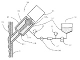
図1に、本発明の液体供給装置を適用した加圧型混練装置のイメージ図を、図2に、一例の本発明の液体供給装置の構成を示す。本図は、注液停止時の状態を示している。本発明の液体供給装置は、第1の流路開閉手段であるピストンバルブ20と、供給タンク50と、これら2つを繋ぐ配管経路と、この配管経路に設けられたピストンバルブ20と別構造の第2の流路開閉手段である開閉バルブ30と、供給ポンプ40を含み構成される。
In order to deal with such a problem, the present inventors have studied a liquid supply apparatus that can inject a liquid into a pressurized container such as the above-described pressurized kneading apparatus.
FIG. 1 shows an image of a pressure-type kneading apparatus to which the liquid supply apparatus of the present invention is applied, and FIG. 2 shows an example of the configuration of the liquid supply apparatus of the present invention. This figure has shown the state at the time of liquid injection stop. The liquid supply apparatus of the present invention has a
ピストンバルブ20は、供給液体が溜まるシリンダ21と、注液を制御するピストン22と、ピストン22を駆動するエアシリンダ23を含み構成される。シリンダ21の混練槽の壁11に取り付ける側は径が細く絞られて配管21aを形成している。ピストン22の先端側は、配管21aの内径よりわずかに小さい外径に加工された挿入部22aを形成しており、混練材料12が容易にはシリンダ21の内部に侵入しないようになっている。また、ピストン22の中央部は径が大きくなっており、配管21aのエアシリンダ23側端部に押し付けて液体流路が開閉可能な弁部22bを形成している。ピストンバルブ20の流路開閉はシリンダ21が細く絞られて配管21aを形成するまでのテーパー部21bとこれに接するピストン22の弁部22bテーパー面部分の圧着によって行われ、ピストン22の挿入部22aは配管21aへの混練材料の進入防止機能を有する。
The
本発明の液体供給装置の基本的な動作について図10にフローチャートで示すとともに、以下で説明する。先ず図2に注液停止時の状態を示す。シリンダ21内でピストン22は、エアシリンダ23により混練槽1側に移動しており。弁部22bは配管21aの端部のテーパー部21bに圧着されて液体流路を遮断している。開閉バルブ30は閉、供給ポンプ40は停止状態であり、供給タンク50と混練槽1とを結ぶ配管経路は完全に遮断されている。
The basic operation of the liquid supply apparatus of the present invention is shown in the flowchart of FIG. 10 and will be described below. First, FIG. 2 shows a state when the injection is stopped. The
次に図3に注液時の状態を示す。供給ポンプ40の駆動、開閉バルブ30の開動作と同時にエアシリンダ23が動作(A)し、ピストン22がエアシリンダ側に移動(B)する。これに伴い弁部22bが配管21aの壁面11側の端部から離れてシリンダ21内部に移動することにより液体流路の遮断が解除(C)され、液体の流通が可能になる。供給タンク50内の液体51が供給ポンプ40により開になった開閉バルブ30を経由してシリンダ21に供給され、配管21aを経由して混練槽内に注液(D)される。
Next, FIG. 3 shows a state during injection. The air cylinder 23 operates (A) simultaneously with the driving of the
所定量の注液が完了すると、エアシリンダ23が動作してピストン22が、混練槽1側に移動(E)して、挿入部22aが配管21aに挿入され、これに伴い弁部22bが配管21aのテーパー部21bに押し付けられて、混練材料12の配管21aへの進入を防ぐと伴に液体流路が遮断(F)される。これと同時に開閉バルブ30が閉鎖され、供給ポンプ40が停止(G)する。これにより、再び供給タンク50と混練槽1とを結ぶ配管経路は完全に遮断される。
When a predetermined amount of liquid injection is completed, the air cylinder 23 operates to move the
本発明の液体供給装置は、第1の流路開閉手段であるピストンバルブ20の主機能を加圧型混練装置などの加圧容器内からの逆流物による注液孔5、配管21aの閉塞防止とし、供給ポンプ40とピストンバルブ20の間に配置した第2の流路開閉手段である開閉バルブ30を主要な注液制御とすることにより、ピストンバルブ20部分で逆流や凝集によって弁部22bとシリンダ21の内壁との間に混練材料12が挟まっても確実に注液を停止できるようにしたものである。ここで用いる第2の流路開閉手段である開閉バルブ30としては瞬時に完全な流路開閉が行えるバルブであれば特に制限は無く、ボールバルブ、ポペットバルブ、バタフライバルブ、シリンダバルブなどを用いることが出来る。
In the liquid supply apparatus of the present invention, the main function of the
更にこれら一連の、注液開始/停止のバルブ動作時において、加圧容器側からピストンバルブ20側に混練材料が逆流することを防ぐための好ましい動作について説明する。図11に示したフローチャートのようにピストンバルブ20が開状態の間(ピストンバルブ20の開動作する瞬間から閉作動が終了するまでの間)は必ず前記のピストンバルブ20から加圧容器への注液圧力が加圧容器側からピストンバルブ20内部への逆流圧力より高くなるように供給ポンプ40の運転停止タイミング、ピストンバルブ20と開閉バルブ30の開閉タイミング制御を行うことが好ましい。こうすることにより、配管21aを混練材料が逆流するのを防ぐことができる。
Further, a preferable operation for preventing the kneaded material from flowing backward from the pressurized container side to the
具体的には、注液開始時にはピストンバルブ20を閉のまま開閉バルブ30を開動作すると同時に供給ポンプ40を駆動(A)して、圧力計41により示される供給側の圧力値が混練槽側からシリンダ21内へ逆流する圧力値を超えた(B)ところで、ピストンバルブ20の開動作(C)を行い、流体経路の遮断を解除(D)すれば、混練材料12が逆流することなく混練漕内に注液(E)することができるので好ましい。
Specifically, at the start of liquid injection, the opening and closing
また、注液停止時には、まずピストンバルブ20を閉動作(F)して流体経路を遮断(G)し、圧力計42により示されるシリンダ21内の圧力値が注液時の圧力より少し高くなった(H)時に、開閉バルブ30を閉(I)、供給ポンプ40を駆動停止(J)とすると、シリンダ21内の圧力を加圧容器側からの圧力より高く維持して注液停止できるので、混練材料が逆流することがないので好ましい。
When the injection is stopped, the
本発明の供給装置の場合は、仮にピストンバルブ20中に、供給される液体51が樹脂液や粉体を含むスラリー液でありこれらの固形分がシリンダ内に凝集付着しても、ピストンバルブ20を閉状態で開閉バルブ30を開操作、供給ポンプ40を駆動して供給圧力を上げた状態の後、ピストンバルブ20を一気に開状態にすると高圧の液体51を勢いよく供給することができるので、凝集付着物をシリンダ21の外に押し出すことができ、付着防止を図ることが出来る。
In the case of the supply device of the present invention, even if the liquid 51 to be supplied is a slurry liquid containing a resin liquid or a powder in the
前述の制御例は一例であり、各装置の運転、開閉タイミングは本順序に制約されるものではない。第1の流路開閉装置であるピストンバルブ20が開動作する瞬間から閉作動が終了するまでの間、常にピストンバルブ20から加圧容器への注液圧が、加圧容器側からピストンバルブ20側へ混練物が逆流する逆流圧以上の圧力となるようにポンプの回転数、運転/停止タイミング、両開閉装置の開閉タイミング、開度を制御すればよい。
The above control example is an example, and the operation and opening / closing timing of each device are not limited to this order. From the moment when the
上記の各バルブ、供給ポンプの動作および制御をより確実にするためには、ピストンバルブ20と開閉バルブ30とを結ぶ配管長と配管内径との関係を(配管長/配管内径)<200とすることが好ましい。この範囲が好ましいのは、この範囲を超えて配管長が長くなると、各バルブの開閉動作、供給ポンプの動作を上述のように制御しようとしても、配管内に滞留する気体(空気)の影響や液体の慣性等の影響が大きくなって、流体の送液、停止の応答遅れが発生し、制御が困難になる場合があるからである。
In order to make the operation and control of each of the valves and the supply pump more reliable, the relationship between the pipe length connecting the
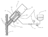
図6に第2の流路開閉手段である開閉バルブ30の無い液体供給装置の例を示す。この例では、液体供給装置の構成が簡単になって良いように見えるが、本発明者らの検討によると種々問題があることが判明した。
この例の液体供給装置の動作について説明する。図6に注液停止時の状態を示す。シリンダ21内でピストン22は、エアシリンダ23により混練槽1側に移動しており、弁部22bは配管21aの端部のテーパー面21bに圧着されて液体流路を遮断している。供給ポンプ40は停止状態であり、供給タンク50と混練槽1とを結ぶ配管経路は完全に遮断されている。
FIG. 6 shows an example of a liquid supply device without the opening / closing
The operation of the liquid supply apparatus of this example will be described. FIG. 6 shows a state when the injection is stopped. In the
図7に注液時の状態を示す。供給ポンプ40の駆動と同時にエアシリンダ23が動作し、ピストン22がエアシリンダ側に移動する。これに伴い弁部22bが配管21aの壁面11側の端部から離れてシリンダ21内部に移動することにより液体流路の遮断が解除され、液体の流通が可能になる。供給タンク50内の液体51が供給ポンプ40によりシリンダ21に供給され、配管21aを経由して混練槽内に注液される。
FIG. 7 shows the state during injection. The air cylinder 23 operates simultaneously with the driving of the
所定量の注液が完了すると、エアシリンダ23が動作してピストン22が、混練槽1側に移動して、挿入部22aが配管21aに挿入され、これに伴い弁部22bが配管21aの端部に押し付けられて、混練材料12の配管21aへの進入を防ぐと伴に液体流路が遮断される。これと同時に供給ポンプ40が停止する。これにより、再び供給タンク50と混練槽1とを結ぶ配管経路は完全に遮断される。
When a predetermined amount of liquid injection is completed, the air cylinder 23 is operated, the
各個所の動作タイミングが順次正常に行われると注液は問題なく行なわれるはずであるが、実際の使用に当っては、供給ポンプ40の慣性駆動、エアシリンダ23の駆動抵抗や経年劣化による動作遅れなどが必ず発生し、各装置の動作タイミングは微妙にずれ必ずしも安定しない。
When the operation timing of each part is normally performed in succession, the liquid injection should be performed without any problem. However, in actual use, the operation is driven by the inertial drive of the
例えば、注液状態から注液停止になる時に、供給ポンプが停止すると同時にピストン22が混練槽側に移動して、弁部22bが配管21aの端部に押し付けられて、液体の流通が遮断されるタイミングが少し遅れると、図8に示すように、混練材料12が逆流する場合がある。このように混練成分がシリンダ21の内部に逆流すると、挿入部22aを配管21aに押し込んだとしても、弁部22bとシリンダ21のテーパー部21bとの間に混練材料12が挟まって、図9に示す状態となり弁部22bを21bに押し付けて、流路を完全に遮断することができなくり閉鎖機能が不完全となる。
For example, when the liquid injection is stopped from the liquid injection state, the
注液停止状態から注液状態にピストンバルブ22が開作動する時に、液体の流れに遅れが発生して、シリンダ21内の液圧が混練槽より低くなった場合においても、シリンダ21の配管21aの流路が開放された瞬間に混練物12が逆流して図8に示すようになり、シリンダ21内部に付着することがある。この場合もピストンバルブ20の閉作動時には図9に示す状態となり、弁部22bを配管21aの端部に押し付けて、流路を完全に遮断することができなくなり閉鎖機能が不完全となる。
Even when the
ピストン22の先端側22aは、配管21aに抜き差しすることから配管21aの内径よりわずかに小さい外径に加工されているため、この抜差し部分で完全に流路の遮断はできない。一旦、上記の逆流による付着が発生すると、その後は、流路の遮断が不完全になり、混練成分12の逆流がますます増加する、もしくは供給ポンプ40の停止指令後も慣性で駆動された場合、余分な注液が行われ、注液精度が安定しなくなる。
Since the distal end side 22a of the
液体供給装置によって注液される液体51が付着性の強い樹脂液や粉体を含むスラリー液の場合には混練材料12の逆流が発生しなくとも、ピストンバルブ20の内部、特に弁部22bとシリンダ21のテーパー部21bの間に凝集物が付着して、同様に図9に示す状態となり、流路を完全に遮断することが出来なくなり閉鎖機能が不完全となる。
一度、ピストンバルブ20内で逆流、凝集物による付着が発生した場合、シリンダ21を分解して内部清掃を行い、付着物を排除しなければならず、多大な工数が必要となる。
In the case where the liquid 51 injected by the liquid supply device is a slurry liquid containing a resin liquid or a powder having strong adhesion, the inside of the
Once the back flow and adhesion due to aggregates occur in the
本発明の液体供給装置では、ピストンバルブ20と供給ポンプ40とを結ぶ配管経路の間に開閉バルブ30を配置し、液体の注液圧力を適正に制御しているため、前述の問題は発生しない。また、仮にピストンバルブ20内で混練材料12の逆流、付着や注液材料51の付着が生じた場合でも、注液の制御は別設置のバルブ30で確実に行われるため、液体供給装置の給液制御も問題なく行われる。
In the liquid supply apparatus of the present invention, the opening / closing
本発明によれば、加圧容器に、液体を安定して確実に供給することができる。
According to the present invention, a liquid can be stably and reliably supplied to a pressurized container.
1 混練槽
2 ブレード
3 回転軸
4 加圧蓋
5 注液孔
9 従来の加圧型混練装置
10 本発明の液体供給装置を適用した一例の加圧型混練装置
11 混練槽の壁面
12 混練材料
20 ピストンバルブ
21 シリンダ
21a 配管
21b テーパー部
22 ピストン
22a 挿入部
22b 弁部
23 エアシリンダ
30 開閉バルブ
40 供給ポンプ
41、42 圧力計
43 流量計
50 供給タンク
51 液体
DESCRIPTION OF
Claims (3)
前記加圧容器に接した注液流路にピストン形状の弁構造体を抜き差しして、流路の開閉を制御する第1の流路開閉手段であるピストンバルブが配置され、
前記ピストンバルブは供給液体が溜まるシリンダ、注液を制御するピストン、前記ピストンを駆動するエアシリンダを含み
前記ピストンは弁部テーパー面部分を有し、
前記シリンダは、前記ピストンの移動により前記弁部テーパー面部分が押しつけられるテーパー部を有し、
前記供給ポンプと前記ピストンバルブとの間にさらに別の弁構造を有する第2の流路開閉手段が配置されていることを特徴とする液体供給装置。 A liquid supply device for injecting liquid from a tank to a pressurized container via a supply pump,
A piston valve, which is a first channel opening / closing means for controlling the opening and closing of the channel, is arranged by inserting and removing a piston-shaped valve structure into and from the liquid injection channel in contact with the pressurized container,
The piston valve includes a cylinder for storing a supply liquid, a piston for controlling liquid injection, and an air cylinder for driving the piston.
The piston has a valve portion tapered surface portion;
The cylinder has a tapered portion against which the valve portion tapered surface portion is pressed by the movement of the piston,
A liquid supply apparatus, wherein a second flow path opening / closing means having another valve structure is arranged between the supply pump and the piston valve.
第1の流路開閉手段が開状態の場合は、必ず第1の流路開閉手段と第2の流路開閉手段との間の液圧力が加圧容器内から供給装置側へ逆流する液圧力より高くなるように供給ポンプの運転/停止、両開閉装置の開/閉タイミングおよび開度を制御することを特徴とする液体供給方法。 A liquid supply method for injecting liquid into a pressurized container using the liquid supply apparatus shown in claim 1,
When the first flow path opening / closing means is in the open state, the liquid pressure between the first flow path opening / closing means and the second flow path opening / closing means always flows back from the inside of the pressurized container to the supply device side. A liquid supply method characterized by controlling the operation / stop of the supply pump and the opening / closing timing and opening degree of both opening / closing devices so as to be higher.
Priority Applications (1)
| Application Number | Priority Date | Filing Date | Title |
|---|---|---|---|
| JP2010158371A JP5674095B2 (en) | 2010-07-13 | 2010-07-13 | Liquid supply device |
Applications Claiming Priority (1)
| Application Number | Priority Date | Filing Date | Title |
|---|---|---|---|
| JP2010158371A JP5674095B2 (en) | 2010-07-13 | 2010-07-13 | Liquid supply device |
Publications (2)
| Publication Number | Publication Date |
|---|---|
| JP2012020212A JP2012020212A (en) | 2012-02-02 |
| JP5674095B2 true JP5674095B2 (en) | 2015-02-25 |
Family
ID=45774943
Family Applications (1)
| Application Number | Title | Priority Date | Filing Date |
|---|---|---|---|
| JP2010158371A Active JP5674095B2 (en) | 2010-07-13 | 2010-07-13 | Liquid supply device |
Country Status (1)
| Country | Link |
|---|---|
| JP (1) | JP5674095B2 (en) |
Families Citing this family (1)
| Publication number | Priority date | Publication date | Assignee | Title |
|---|---|---|---|---|
| JP5838014B2 (en) * | 2012-11-09 | 2015-12-24 | 株式会社ノリタケカンパニーリミテド | Fluid mixing device |
Family Cites Families (7)
| Publication number | Priority date | Publication date | Assignee | Title |
|---|---|---|---|---|
| JPS60143821A (en) * | 1983-12-28 | 1985-07-30 | Hitachi Maxell Ltd | Apparatus for supplying small particle body |
| JPS60187325A (en) * | 1984-03-06 | 1985-09-24 | Noritake Co Ltd | Fluid injection method and device for dispersion mixer |
| JPH0737703Y2 (en) * | 1989-11-28 | 1995-08-30 | 株式会社ノリタケカンパニーリミテド | Dispersion mixer |
| JP2760931B2 (en) * | 1993-03-10 | 1998-06-04 | 株式会社 栗本鐵工所 | Kneading machine with liquid injection mechanism |
| JP2004255231A (en) * | 2003-02-24 | 2004-09-16 | Katsutoshi Masuda | Fluid delivery pump |
| JP4772310B2 (en) * | 2004-09-30 | 2011-09-14 | 株式会社栗本鐵工所 | Kneading machine |
| JP2007069504A (en) * | 2005-09-08 | 2007-03-22 | Sumitomo Chemical Co Ltd | Injection nozzle |
-
2010
- 2010-07-13 JP JP2010158371A patent/JP5674095B2/en active Active
Also Published As
| Publication number | Publication date |
|---|---|
| JP2012020212A (en) | 2012-02-02 |
Similar Documents
| Publication | Publication Date | Title |
|---|---|---|
| US10946354B2 (en) | Dynamic mixer dispense valve for two-component high-viscosity high-ratio compounds | |
| CN104815783B (en) | Glue-pouring machine equipment | |
| JP7384988B2 (en) | equipment for mixing | |
| CN110997256A (en) | Systems for coating building materials | |
| CN107850239A (en) | Needle-valve | |
| JP5758968B2 (en) | In-line injection molding machine with plunger | |
| JP2012020212A (en) | Liquid supply device | |
| KR102300089B1 (en) | Fluid-material ejecting apparatus | |
| CN211800111U (en) | A plain bumper mixing arrangement that shakes for cladding of graphite tar liquid phase | |
| AT513879B1 (en) | Continuous mixer | |
| US20210322939A1 (en) | Dynamic mixer dispense valvefor two-component high-viscosity high ratio compounds having quick change cartridge | |
| WO2019128026A1 (en) | Sand mixer and sand mixing process | |
| CN112654481B (en) | Apparatus and method for producing reactive plastics | |
| JP4965208B2 (en) | Two-component mixing device | |
| JP3776616B2 (en) | Two-component mixing method | |
| JP2006095469A (en) | Kneading machine | |
| JP4234339B2 (en) | Liquid applicator | |
| CN212498972U (en) | Powder paving device | |
| JP2014188513A (en) | Liquid injection method for kneader | |
| JPS6260621A (en) | Injection method in injection unit | |
| CN222060848U (en) | Double-component stretch yarn mixer | |
| CN208697698U (en) | Aggregate bin discharging device | |
| CN207546381U (en) | A kind of drawing mechanism | |
| JP3143195U (en) | Mixing device with pressure control mechanism | |
| CN220026681U (en) | Mixing device of formaldehyde scavenger |
Legal Events
| Date | Code | Title | Description |
|---|---|---|---|
| A621 | Written request for application examination |
Free format text: JAPANESE INTERMEDIATE CODE: A621 Effective date: 20130520 |
|
| A977 | Report on retrieval |
Free format text: JAPANESE INTERMEDIATE CODE: A971007 Effective date: 20140311 |
|
| A131 | Notification of reasons for refusal |
Free format text: JAPANESE INTERMEDIATE CODE: A131 Effective date: 20140403 |
|
| A521 | Request for written amendment filed |
Free format text: JAPANESE INTERMEDIATE CODE: A523 Effective date: 20140516 |
|
| TRDD | Decision of grant or rejection written | ||
| A01 | Written decision to grant a patent or to grant a registration (utility model) |
Free format text: JAPANESE INTERMEDIATE CODE: A01 Effective date: 20141217 |
|
| A61 | First payment of annual fees (during grant procedure) |
Free format text: JAPANESE INTERMEDIATE CODE: A61 Effective date: 20141218 |
|
| R150 | Certificate of patent or registration of utility model |
Ref document number: 5674095 Country of ref document: JP Free format text: JAPANESE INTERMEDIATE CODE: R150 |
|
| S111 | Request for change of ownership or part of ownership |
Free format text: JAPANESE INTERMEDIATE CODE: R313113 |
|
| R350 | Written notification of registration of transfer |
Free format text: JAPANESE INTERMEDIATE CODE: R350 |
|
| R250 | Receipt of annual fees |
Free format text: JAPANESE INTERMEDIATE CODE: R250 |
|
| R250 | Receipt of annual fees |
Free format text: JAPANESE INTERMEDIATE CODE: R250 |
|
| R250 | Receipt of annual fees |
Free format text: JAPANESE INTERMEDIATE CODE: R250 |
|
| R250 | Receipt of annual fees |
Free format text: JAPANESE INTERMEDIATE CODE: R250 |
|
| R250 | Receipt of annual fees |
Free format text: JAPANESE INTERMEDIATE CODE: R250 |
|
| R250 | Receipt of annual fees |
Free format text: JAPANESE INTERMEDIATE CODE: R250 |
|
| R250 | Receipt of annual fees |
Free format text: JAPANESE INTERMEDIATE CODE: R250 |
|
| R250 | Receipt of annual fees |
Free format text: JAPANESE INTERMEDIATE CODE: R250 |
|
| R250 | Receipt of annual fees |
Free format text: JAPANESE INTERMEDIATE CODE: R250 |