JP5663168B2 - Single-bit segmentation indicator - Google Patents
Single-bit segmentation indicator Download PDFInfo
- Publication number
- JP5663168B2 JP5663168B2 JP2009541263A JP2009541263A JP5663168B2 JP 5663168 B2 JP5663168 B2 JP 5663168B2 JP 2009541263 A JP2009541263 A JP 2009541263A JP 2009541263 A JP2009541263 A JP 2009541263A JP 5663168 B2 JP5663168 B2 JP 5663168B2
- Authority
- JP
- Japan
- Prior art keywords
- rlc
- pdu
- sdu
- bit
- indicator
- Prior art date
- Legal status (The legal status is an assumption and is not a legal conclusion. Google has not performed a legal analysis and makes no representation as to the accuracy of the status listed.)
- Active
Links
- 230000011218 segmentation Effects 0.000 title description 29
- 230000005540 biological transmission Effects 0.000 claims description 15
- 238000000034 method Methods 0.000 claims description 15
- 238000010295 mobile communication Methods 0.000 claims description 2
- 238000004891 communication Methods 0.000 description 16
- 230000009286 beneficial effect Effects 0.000 description 1
- 230000008901 benefit Effects 0.000 description 1
- 230000008859 change Effects 0.000 description 1
- 238000010586 diagram Methods 0.000 description 1
- 238000005516 engineering process Methods 0.000 description 1
- 230000007246 mechanism Effects 0.000 description 1
- 238000012986 modification Methods 0.000 description 1
- 230000004048 modification Effects 0.000 description 1
- 230000008569 process Effects 0.000 description 1
Images


Classifications
-
- H—ELECTRICITY
- H04—ELECTRIC COMMUNICATION TECHNIQUE
- H04L—TRANSMISSION OF DIGITAL INFORMATION, e.g. TELEGRAPHIC COMMUNICATION
- H04L1/00—Arrangements for detecting or preventing errors in the information received
- H04L1/12—Arrangements for detecting or preventing errors in the information received by using return channel
- H04L1/16—Arrangements for detecting or preventing errors in the information received by using return channel in which the return channel carries supervisory signals, e.g. repetition request signals
- H04L1/18—Automatic repetition systems, e.g. Van Duuren systems
- H04L1/1867—Arrangements specially adapted for the transmitter end
- H04L1/1887—Scheduling and prioritising arrangements
-
- H—ELECTRICITY
- H04—ELECTRIC COMMUNICATION TECHNIQUE
- H04W—WIRELESS COMMUNICATION NETWORKS
- H04W28/00—Network traffic management; Network resource management
- H04W28/02—Traffic management, e.g. flow control or congestion control
- H04W28/06—Optimizing the usage of the radio link, e.g. header compression, information sizing, discarding information
- H04W28/065—Optimizing the usage of the radio link, e.g. header compression, information sizing, discarding information using assembly or disassembly of packets
Description
本発明は一般的には、無線ネットワークにおける高速パケットデータサービスについての無線リンクに関し、特に、IPパケットをRLCプロトコルのデータユニットに分割することと再組立てに関する。 The present invention relates generally to wireless links for high-speed packet data services in wireless networks, and more particularly to dividing and reassembling IP packets into RLC protocol data units.
無線リンク制御(RLC)は無線チャネルによるエラー率を低減するために移動体通信ネットワークで用いられるプロトコルである。前方エラー修正と再送プロトコルの使用により、物理層では通常、1%のオーダのエラー率でパケットを配信することができる。しかしながら、たいていのIPネットワークで用いられるトランスポート制御プロトコル(TCP)は、信頼できる通信のために0.01%のオーダのエラー率を要求している。無線リンク制御(RLC)は物理層でのエラー性能とTCPによる信頼できる通信のための要求との間のギャップを橋渡しする。 Radio Link Control (RLC) is a protocol used in mobile communication networks to reduce the error rate due to radio channels. Through the use of forward error correction and retransmission protocols, the physical layer can typically deliver packets with an error rate on the order of 1%. However, the transport control protocol (TCP) used in most IP networks requires an error rate on the order of 0.01% for reliable communication. Radio Link Control (RLC) bridges the gap between error performance at the physical layer and the requirement for reliable communication over TCP.
RLCプロトコルは、無線通信チャネルによるIPパケットのエラーのない、順番通りの配信を担当する。RLCは、RLCサービスデータユニット(SDU)とも呼ばれるIPパケットを、無線通信チャネルによる送信のために、RLCプロトコルデータユニット(PDU)と呼ばれるより小さいユニットに分割する。再送プロトコルは、各RLC PDUの配信を保証するために用いられる。RLC PDUが受信器側で失われると、その受信器は失われたRLC PDUの再送を要求することができる。RLC SDUはその受信器で受信された複数のRLC PDUから再び組み立てられる。 The RLC protocol is responsible for in-order delivery without errors in IP packets over the wireless communication channel. RLC divides IP packets, also called RLC service data units (SDUs), into smaller units called RLC protocol data units (PDUs) for transmission over a wireless communication channel. The retransmission protocol is used to guarantee the delivery of each RLC PDU. If an RLC PDU is lost at the receiver side, the receiver can request retransmission of the lost RLC PDU. The RLC SDU is reassembled from multiple RLC PDUs received at that receiver.
IPパケットは大きいこともあるので、RLCはIPパケットの分割や連結のための機構を提供している。分割により複数のIPパケットは送信のために多数のRLC PDUに分割される。連結により多数のIPパケットの部分部分が1つのRLC PDUに含めることができる。RLC PDUのヘッダは従来より、長さインジケータ(LI)を含んでおり、これが各IPパケットの長さを示し、受信器でのIPパケットの再組立を可能にしている。 Since IP packets can be large, RLC provides a mechanism for splitting and concatenating IP packets. Due to the division, a plurality of IP packets are divided into a number of RLC PDUs for transmission. Due to the concatenation, parts of multiple IP packets can be included in one RLC PDU. RLC PDU headers conventionally include a length indicator (LI), which indicates the length of each IP packet and allows reassembly of the IP packet at the receiver.
第3世代パートナーシッププロジェクト(3GPP)により標準化された広帯域符号分割多元接続(WCDMA)の標準のリリース7に関し、連結の機能を削除して、RLCヘッダの長さインジケータをセグメンテーション・インジケータで置換することが提案された。2ビットのセグメンテーション・インジケータは次の4つのセグメンテーションの可能性の内の1つを示唆するために用いられることが提案された。その4つとは以下の通りである。即ち、
・1つのRLC SDUを正確に1つのRLC PDUにフィットさせること
・RLC SDUはRLC PDUで始まり、次にRLC PDUに続くこと
・RLC SDUのセグメントがRLC PDUを満たすこと
・RLC SDUはRLC PDUで終了すること
である。
For Release 7 of the Standard for Wideband Code Division Multiple Access (WCDMA) standardized by the 3rd Generation Partnership Project (3GPP), removing the concatenation function and replacing the length indicator in the RLC header with a segmentation indicator was suggested. It has been proposed that the 2-bit segmentation indicator be used to suggest one of the following four segmentation possibilities. The four are as follows. That is,
-Fit one RLC SDU to exactly one RLC PDU-RLC SDU starts with RLC PDU and then follows RLC PDU-RLC SDU segment fills RLC PDU-RLC SDU with RLC PDU It is to end.
上記の提案は、RLC PDUに関して新しく確認応答されるモードのフォーマットを必要とする。従って、RLC PDUのついて現存する確認応答モードのフォーマットの再利用を可能とするセグメンテーション・インジケータをもつことが本発明の目的である。 The above proposal requires a newly acknowledged mode format for RLC PDUs. Accordingly, it is an object of the present invention to have a segmentation indicator that allows reuse of existing acknowledgment mode formats for RLC PDUs.
本発明では、第1の送信フォーマットに従うデータユニットを第2の送信フォーマットに従うデータユニットに分割する方法を提案する。第1の送信フォーマットに従うデータユニットは、2つ以上のセグメントに分割され、ヘッダが各セグメントに付加されて第2の送信フォーマットに従うデータユニットを創成する。1ビットのセグメンテーション・インジケータが第2の送信フォーマットに従うデータユニットのヘッダに付加されて、第1の送信フォーマットに従うデータユニットが第2の送信フォーマットに従うデータユニットで終了するかどうかを示す。 The present invention proposes a method for dividing a data unit according to a first transmission format into data units according to a second transmission format. A data unit according to the first transmission format is divided into two or more segments and a header is added to each segment to create a data unit according to the second transmission format. A 1-bit segmentation indicator is added to the header of the data unit according to the second transmission format to indicate whether the data unit according to the first transmission format ends with a data unit according to the second transmission format.
本発明はまた、本発明に従う方法を実行するために構成されたRLCプロセッサを含む送信器に関したものでもある。 The invention also relates to a transmitter comprising an RLC processor configured to carry out the method according to the invention.
1つの代表的な実施例では、第1の送信フォーマットに従うデータユニットはRLC SDUを有し、第2の送信フォーマットに従うデータユニットはRLC PDUを有している。連結が用いられないと仮定するなら、複数のRLC PDUに順序番号を付けることと組み合わせて、1ビットのセグメンテーション・インジケータは、RLCプロトコルの分割と再組立機能を実行するのに十分である。受信器が、最後のRLC SDUの終わりとなるRLC PDUの順序番号からRLC SDUの始まりを判断しても良い。この情報に基づいて、受信器は1つのRLC SDUに対応する全てのRCL PDUの順序番号を判断しても良い。 In one exemplary embodiment, data units according to the first transmission format have RLC SDUs and data units according to the second transmission format have RLC PDUs. Assuming no concatenation is used, a 1-bit segmentation indicator in combination with ordering multiple RLC PDUs is sufficient to perform the RLC protocol segmentation and reassembly functions. The receiver may determine the start of the RLC SDU from the sequence number of the RLC PDU that ends the last RLC SDU. Based on this information, the receiver may determine the sequence numbers of all RCL PDUs corresponding to one RLC SDU.
本発明により、柔軟なRLC PDUフォーマットのセグメンテーション・インジケーション・フィールドの1ビットが節約でき、新しいFMDフォーマットが規定される場合には、将来の拡張や機能追加のために利用可能なスペアビットが備えられるという利点がある。 The present invention saves one bit in the segmentation indication field of the flexible RLC PDU format and provides a spare bit that can be used for future expansion and function addition when a new FMD format is specified. There is an advantage that
本発明の代表的な実施例を添付図面を参照してより詳細に説明する。 Exemplary embodiments of the present invention will be described in more detail with reference to the accompanying drawings.
さて、図面を参照して説明すると、図1は通信ネットワーク10を図示しており、その図では移動局20が通信チャネル30により基地局40と通信している。基地局40はインターネットのようなIPネットワークへの接続を提供するアクセスネットワーク(AN)の一部である。移動局20はパケットデータを無線通信ネットワーク30を介して基地局40に送信し、また、基地局40から無線通信ネットワーク30を介してパケットデータを受信する。次の検討では基地局40と移動局20は第3世代パートナーシッププロジェクト(3GPP)により標準化された広帯域符号分割多元接続(WCDMA)に従って動作すると仮定するが、ここで説明する原理は他の標準やアクセス技術に対しても適用可能である。
Referring now to the drawings, FIG. 1 illustrates a
WCDMAネットワークではハイブリッドARQが物理層に採用され約1%程度のエラー率を提供している。しかしながら、トランスポート制御プロトコル(TCP)では、信頼できる通信のために0.01%のオーダでのエラー率を要求している。無線リンク制御(RLC)は、物理層でのエラー性能とTCPネットワークによる信頼できる通信のための要求との間のギャップを橋渡しする。RLC機能は移動局20ではRLCプロセッサ22により、基地局40ではRLCプロセッサ42により実現される。
In a WCDMA network, hybrid ARQ is employed in the physical layer and provides an error rate of about 1%. However, the transport control protocol (TCP) requires an error rate on the order of 0.01% for reliable communication. Radio Link Control (RLC) bridges the gap between error performance at the physical layer and the requirements for reliable communication over TCP networks. The RLC function is realized by the RLC
WCDMAでは、送信局(例えば、アップリンク送信では移動局20、ダウンリンク送信では基地局40)におけるRLCプロセッサ22、42はパケットデータ収束プロトコル(PDCP)層から圧縮IPパケットを受信する。そのIPパケットはRLCサービスデータユニット(SDU)としても知られている。RLCは複数のSDUを複数のセグメントへと分割し、各セグメントにヘッダを付加してRLCプロトコルデータユニット(PDU)を創成する。それから、PDUが無線通信チャネル30により受信器へと送信される。アップリンクでは、PDUは移動局20の送信器により基地局40の受信器へと送信される。ダウンリンクでは、PDUは基地局40の送信器により移動局20の受信器へと送信される。受信器のRLCプロセッサ22、42においてPDUの喪失が検出されるとき、受信器は否定確認応答(NACK)を送信し、喪失したPDUの再送を要求する。1つのSDUに対応する複数のPDUが受信されると、SDUが再組立されて上位層のプロトコルへと渡される。
In WCDMA, RLC
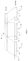
図2は複数のRLC SDUを複数のRLC PDUへと分割する様子を図示している。図2に示されている例では、SDU50が3つのセグメントへと分割され、3つのPDU52を形成する。セグメントの数は、SDU50とPDU52の相対サイズに依存して変えても良い。各PDU52は、ヘッダ54と、SDU50の1つのセグメントを含むペイロード56とを含む。PDU52のサイズは柔軟性があっても良く、運用者はPDU52に関して所定の最大サイズを設定しても良い。セグメンテーション処理中に、RLCプロセッサ22、42はSDU50を最大サイズの基準に基づいてセグメントに分割する。最後のSDU50のサイズは、パッディングや連結が最後のPDU52を満たすことが要求されないように変更することが許されている。
FIG. 2 illustrates how a plurality of RLC SDUs are divided into a plurality of RLC PDUs. In the example shown in FIG. 2,
複数のPDU52から複数のSDUを再組立するために、受信器のRLCプロセッサ22、42は1つのSDU50に対応する複数のPDU52を識別することが必要である。連結が用いられないことを仮定すると、PDU52のヘッダ54のセグメンテーション・インジケータがSDU50の終わりを定めるために用いられても良い。1実施例に従えば、そのセグメンテーション・インジケータは、もしSDU50が次のPDU52に続くなら第1の値にセットされ、もしSDU50がそのPDU52で終了するなら第2の値にセットされる1ビットを有する。例えば、そのセグメンテーション・インジケータが“0”の値にセットされたならSDU50は次のPDU52に続くことを示すようにし、“1”の値にセットされたならSDU50は現在のPDU52で終了することを示すようにしても良い。セグメンテーション・インジケータとPDU52の順序番号とに基づいて、RLCプロセッサ22,42はどのPDU52がSDU50に対応するのかを判断することができる。代わりの実施例では、セグメンテーション・インジケータはSDUの始まりを定めるように用いられても良いが、さもなければ、同じ方法で動作する。
In order to reassemble multiple SDUs from
図3は1実施例に従う代表的なPDUフォーマットを図示している。ヘッダ54は、データ/制御(D/C)フィールド、順序番号フィールド、ポーリングビット(P)フィールド、及び、ヘッダ拡張(HE)フィールドを含んでいる。D/CフィールドはPDU52のタイプ(例えば、データか制御か)を示す。順序番号フィールドはPDU52の第1オクテットと第2オクテットに拡がり、PDU52の順序番号を含む。Pフィールドは状態レポートを要求するために用いられる。HEフィールドは、セグメンテーション・インジケータとスペアビットとを含む2ビットのフィールドである。セグメンテーション・インジケータはPDU52がSDU50の最初のセグメントを含むかどうかを示すために用いられる。スペアビットはセグメンテーション以外の目的のために用いられても良い。代わりの実施例に従えば、別のPDUフォーマットが同じように用いられても良い。あるPDUフォーマットでは、セグメンテーション・インジケータとして用いられる1ビットをもつ分離したセグメンテーション・インジケータ(SI)をもつかもしれない。
FIG. 3 illustrates an exemplary PDU format according to one embodiment. The
以下の表1は図3に示したPDUフォーマットを用いてセグメンテーション・インジケータを実装する1つの方法を例示している。 Table 1 below illustrates one way to implement a segmentation indicator using the PDU format shown in FIG.
表1:セグメンテーション・インジケータ(第1実施例)
┌−−┬−−−−−−−−−−−−−−−−−−−−−−−−−−−−−−┐
| 値| 説 明 |
├−−┼−−−−−−−−−−−−−−−−−−−−−−−−−−−−−−┤
|x0|このRLC PDUのRLC SDUは次のRLC PDUに続く|
├−−┼−−−−−−−−−−−−−−−−−−−−−−−−−−−−−−┤
|x1|RLC SDUはこのRLC PDUで終わる |
└−−┴−−−−−−−−−−−−−−−−−−−−−−−−−−−−−−┘
Table 1: Segmentation indicators (first embodiment)
┌--┬ ----------------------------- ┐
| Value | Description |
├--┼ ----------------------------- ┤
| X0 | The RLC SDU for this RLC PDU follows the next RLC PDU |
├--┼ ----------------------------- ┤
| X1 | RLC SDU ends with this RLC PDU |
└--┴ ----------------------------- ┘
表1に示されているように、SDU50が次のPDU52に続くことを示すために、最下位ビットが“0”にセットされ、SDU50が現在のPDU52で終了することを示すために、“1”にセットされる。この実施例では、“x”で示されている最上位ビットはスペアビットである。そのスペアビットは、例えば、PDU52が始めて送信されたのかどうかを示すために用いられても良い。例えば、そのスペアビット“0”の値がセットされると、PDU52が始めて送信されることを示し、“1”の値がセットされると、そのPDU52は以前に送信されたPDU52の再送であることを示すようにしても良い。PDU52が再送されるかどうかを示すことにより、基地局40で送信される複数のPDU52の優先順位付けを行なうことが可能になり、これは性能上有益である。
As shown in Table 1, the least significant bit is set to “0” to indicate that the
表2はセグメンテーション・インジケータを実装の別の例を示している。 Table 2 shows another example of implementing a segmentation indicator.
表2:セグメンテーション・インジケータ(第2実施例)
┌−−┬−−−−−−−−−−−−−−−−−−−−−−−−−−−−−−┐
| 値| 説 明 |
├−−┼−−−−−−−−−−−−−−−−−−−−−−−−−−−−−−┤
|0x|このRLC PDUのRLC SDUは次のRLC PDUに続く|
├−−┼−−−−−−−−−−−−−−−−−−−−−−−−−−−−−−┤
|1x|RLC SDUはこのRLC PDUで終わる |
└−−┴−−−−−−−−−−−−−−−−−−−−−−−−−−−−−−┘
Table 2: Segmentation indicators (second embodiment)
┌--┬ ----------------------------- ┐
| Value | Description |
├--┼ ----------------------------- ┤
| 0x | The RLC SDU for this RLC PDU follows the next RLC PDU |
├--┼ ----------------------------- ┤
| 1x | RLC SDU ends with this RLC PDU |
└--┴ ----------------------------- ┘
表2に示されているように、最上位ビットがセグメンテーション・インジケータとして機能する一方、最下位ビットはスペアビットとして機能する。SDU50が現在のPDU52で終了するかどうかに依存して、セグメンテーション・インジケータは、“0”或は“1”の値にセットされる。そのスペアビットは、例えば、PDU52が始めて送信されたのか、以前に送信されたPDU52の再送であるのかを示すために用いられても良い。
As shown in Table 2, the most significant bit functions as a segmentation indicator while the least significant bit functions as a spare bit. Depending on whether the
図4は送信器のRLCプロセッサ22、42により実現される、複数のSDU50を複数のPDU52に分割する代表的な手順100を図示している。その送信器は、アップリンク通信用に移動局20に位置するか、ダウンリンク通信用に基地局40に位置している。手順100はRLCプロセッサ22、42が上位層のプロトコルからSDU50を受信するときに開始される(ブロック102)。RLCプロセッサ22、42はSDU50を分割し(ブロック104)、ヘッダを各セグメントに付加して、1つ以上のPDU52を創成する(ブロック106)。創成された各PDU52に関して、RLCプロセッサ22、42はSDU50がPDU52で終了するかどうかを判断する(ブロック108)。もし、終了しないなら、RLCプロセッサ22、42はPDU52のセグメンテーション・インジケータを“0”に等しいようにセットする(ブロック110)。もし、SDU50がPDU52で終了するなら、RLCプロセッサ22、42はPDU52のセグメンテーション・インジケータを“1”に等しいようにセットする(ブロック112)。この手順100は各PDU52に関して繰り返され、最後のPDU52が処理されるときに終了する(ブロック114)。
FIG. 4 illustrates an
図5は受信器のRLCプロセッサ22、42により実現される、受信した複数のPDU52から複数のSDU50を再組立する代表的な手順150を図示している。その受信器は、ダウンリンク通信用に移動局20に位置するか、アップリンク通信用に基地局40に位置している。RLCプロセッサ22、42は1つ以上のSDU50を有する複数のPDU52を受信する(ブロック152)。各SDU50に関し、SDU50の始まりは、最後のSDU50の終わりを含むPDU52の順序番号に基づく(ブロック154)。例えば、最後のSDU50が順序番号nのPDU52で終了するなら、次のSDU50の始まりは順序番号n+1を含むPDU52で始まる。RLCプロセッサ22、42は、PDU52のヘッダのセグメンテーション・インジケータに基づいて、各SDU50の終了を判断する(ブロック156)。RLCプロセッサ22、42はSDUが始まり終了するPDU52の順序番号を知っているので、同じSDU50に属する全てのPDU52を識別して、SDU50を再組立すると良い(ブロック158)。
FIG. 5 illustrates an
もちろん、本発明は、本発明の本質的な特徴を逸脱することなく、ここで具体的に説明した実施例以外の方法で実現することは可能である。この実施例は全ての点において、例示的であり限定的なものではないとして考えられるべきであり、添付の請求の範囲の意味と同等の範囲の中にある全ての変更は請求の範囲の内に含まれることが意図されている。 Of course, the present invention can be implemented by methods other than those specifically described herein without departing from the essential characteristics of the present invention. This example is to be considered in all respects as illustrative and not restrictive, and all modifications within the scope equivalent to the meaning of the appended claims are intended to be within the scope of the claims. It is intended to be included in
Claims (5)
RLC PDUのヘッダの第2番目のオクテットにビットが連続する2ビットのインジケータ・フィールドを挿入する工程と、
RLC SDUが、前記RLC PDUで終了するなら、前記インジケータ・フィールドの1ビットであるインジケータビットに第1の値を設定する工程と、
前記RLC SDUが次のRLC PDUに続くなら、前記インジケータビットに前記第1の値とは異なる第2の値を設定する工程とを有することを特徴とする方法。 A method of dividing a radio link control (RLC) service data unit (SDU) into RLC protocol data units (PDUs) and transmitting in acknowledgment mode, the method comprising:
Inserting a 2-bit indicator field of consecutive bits in the second octet of the header of the RLC PDU;
If the RLC SDU ends with the RLC PDU, setting a first value to an indicator bit that is one bit of the indicator field ;
Setting the indicator bit to a second value different from the first value if the RLC SDU follows the next RLC PDU .
RLC PDUのヘッダの第2番目のオクテットにビットが連続する2ビットのインジケータ・フィールドを挿入し、
RLC SDUが、前記RLC PDUで終了するなら、前記インジケータ・フィールドの1ビットであるインジケータビットに第1の値を設定し、
前記RLC SDUが次のRLC PDUに続くなら、前記インジケータビットに前記第1の値とは異なる第2の値を設定するように構成されていることを特徴とする送信器。 A transmitter in a mobile communication system having an RLC processor that divides a radio link control (RLC) service data unit (SDU) into RLC protocol data units (PDUs) and transmits in acknowledgment mode, the RLC processor comprising: ,
Insert a 2-bit indicator field with consecutive bits in the second octet of the RLC PDU header;
If the RLC SDU ends with the RLC PDU, set a first value to the indicator bit which is one bit of the indicator field ;
A transmitter configured to set the indicator bit to a second value different from the first value if the RLC SDU follows the next RLC PDU .
Applications Claiming Priority (3)
| Application Number | Priority Date | Filing Date | Title |
|---|---|---|---|
| SE0602745 | 2006-12-15 | ||
| SE0602745-2 | 2006-12-15 | ||
| PCT/SE2007/050968 WO2008073043A2 (en) | 2006-12-15 | 2007-12-10 | Single bit segmentation indicator |
Related Child Applications (1)
| Application Number | Title | Priority Date | Filing Date |
|---|---|---|---|
| JP2014248369A Division JP2015092694A (en) | 2006-12-15 | 2014-12-08 | Single bit segmentation indicator |
Publications (3)
| Publication Number | Publication Date |
|---|---|
| JP2010514252A JP2010514252A (en) | 2010-04-30 |
| JP2010514252A5 JP2010514252A5 (en) | 2011-01-06 |
| JP5663168B2 true JP5663168B2 (en) | 2015-02-04 |
Family
ID=39512210
Family Applications (3)
| Application Number | Title | Priority Date | Filing Date |
|---|---|---|---|
| JP2009541263A Active JP5663168B2 (en) | 2006-12-15 | 2007-12-10 | Single-bit segmentation indicator |
| JP2014248369A Pending JP2015092694A (en) | 2006-12-15 | 2014-12-08 | Single bit segmentation indicator |
| JP2016112904A Active JP6322667B2 (en) | 2006-12-15 | 2016-06-06 | Single-bit segmentation indicator |
Family Applications After (2)
| Application Number | Title | Priority Date | Filing Date |
|---|---|---|---|
| JP2014248369A Pending JP2015092694A (en) | 2006-12-15 | 2014-12-08 | Single bit segmentation indicator |
| JP2016112904A Active JP6322667B2 (en) | 2006-12-15 | 2016-06-06 | Single-bit segmentation indicator |
Country Status (4)
| Country | Link |
|---|---|
| US (1) | US20100046448A1 (en) |
| EP (1) | EP2092676A4 (en) |
| JP (3) | JP5663168B2 (en) |
| WO (1) | WO2008073043A2 (en) |
Families Citing this family (10)
| Publication number | Priority date | Publication date | Assignee | Title |
|---|---|---|---|---|
| US20090175175A1 (en) * | 2008-01-04 | 2009-07-09 | Interdigital Patent Holdings, Inc. | Radio link control reset using radio resource control signaling |
| KR102059042B1 (en) * | 2013-05-10 | 2020-02-11 | 주식회사 팬택 | Method and apparatus of in sequence delivery considering multi-flow in dual connectivity system |
| US9361106B2 (en) * | 2013-12-27 | 2016-06-07 | Intel Corporation | SMS4 acceleration processors, methods, systems, and instructions |
| US9513913B2 (en) * | 2014-07-22 | 2016-12-06 | Intel Corporation | SM4 acceleration processors, methods, systems, and instructions |
| US9467279B2 (en) | 2014-09-26 | 2016-10-11 | Intel Corporation | Instructions and logic to provide SIMD SM4 cryptographic block cipher functionality |
| CN110505656B (en) | 2016-09-30 | 2020-07-24 | 华为技术有限公司 | Data processing method, device and system |
| BR112019008903A2 (en) | 2016-11-04 | 2019-08-13 | Beijing Xiaomi Mobile Software Co Ltd | method and device for generating protocol data unit (pdu) packets |
| US20200205224A1 (en) * | 2017-05-02 | 2020-06-25 | Lg Electronics Inc. | Method and device for receiving data unit |
| US10602563B2 (en) * | 2017-06-09 | 2020-03-24 | Samsung Electronics Co., Ltd. | Method and apparatus for supporting RLC UM mode operation in next generation mobile communication system |
| CN109041120A (en) * | 2017-06-12 | 2018-12-18 | 中国移动通信有限公司研究院 | Data transmission method, device and computer readable storage medium |
Family Cites Families (21)
| Publication number | Priority date | Publication date | Assignee | Title |
|---|---|---|---|---|
| US5883893A (en) * | 1996-09-10 | 1999-03-16 | Cisco Technology, Inc. | ATM voice transport protocol |
| KR20000075358A (en) * | 1999-05-27 | 2000-12-15 | 윤종용 | Variable-length data transmitting and receiving apparatus in accordance with radio link protocol for a mobile telecommunication system and method thereof |
| CN1202643C (en) * | 2000-10-07 | 2005-05-18 | Lg电子株式会社 | Radio communication system with radio chain-circuit control layer and data processing method |
| DE10054473A1 (en) * | 2000-11-03 | 2002-05-08 | Siemens Ag | Method for exchanging data packets between two service providers of a radio transmission system |
| US7668176B2 (en) * | 2001-01-18 | 2010-02-23 | Alcatel-Lucent Usa Inc. | Universal mobile telecommunications system (UMTS) quality of service (QoS) supporting variable QoS negotiation |
| US6961349B2 (en) * | 2001-05-30 | 2005-11-01 | Telefonaktiebolaget Lm Ericsson (Publ) | Handling TCP protocol for connections transmitted in parallel over radio link |
| US7542482B2 (en) * | 2001-08-16 | 2009-06-02 | Qualcomm Incorporated | Method and apparatus for message segmentation in a wireless communication system |
| US7289535B2 (en) * | 2002-03-15 | 2007-10-30 | Freescale Semiconductor, Inc. | Method of accommodating fragmentation and burst in a wireless protocol |
| ATE506822T1 (en) * | 2003-09-23 | 2011-05-15 | Panasonic Corp | PROTOCOL CONTEXT TRANSMISSION IN A MOBILE RADIO COMMUNICATION SYSTEM |
| US7586922B2 (en) * | 2004-03-12 | 2009-09-08 | Telefonaktiebolaget Lm Ericsson (Publ) | Providing higher layer packet/frame boundary information in GRE frames |
| KR20050095419A (en) * | 2004-03-26 | 2005-09-29 | 삼성전자주식회사 | Method for efficiently utilizing radio resources of voice over internet protocol in a mobile telecommunication system |
| US7475323B2 (en) * | 2004-08-20 | 2009-01-06 | Qualcomm Incorporated | Method and apparatus for receiving a control channel in a wireless communication system |
| CN100589342C (en) * | 2004-12-21 | 2010-02-10 | 三星电子株式会社 | Apparatus and method for transmitting data in a communication system |
| ATE538553T1 (en) * | 2005-01-05 | 2012-01-15 | Nokia Corp | USING THE FP HEADER TO SIGNAL TO THE RNC THAT NODE B COULD NOT DETERMINE THE NUMBER OF RETRANSMISSIONS |
| WO2006083149A1 (en) * | 2005-02-07 | 2006-08-10 | Samsung Electronics Co., Ltd. | Method and apparatus for requesting/transmitting status report of a mobile communication system |
| EP1855494A4 (en) * | 2005-03-04 | 2012-03-07 | Fujitsu Ltd | Wireless communication apparatus |
| KR100913900B1 (en) * | 2005-05-04 | 2009-08-26 | 삼성전자주식회사 | A method and apparatus for transmitting/receiving packet data using predefined length indicator in mobile communication system |
| TWI307589B (en) * | 2005-05-18 | 2009-03-11 | Innovative Sonic Ltd | Method and apparatus of data segmentation in a mobile communications system |
| JP4449823B2 (en) * | 2005-05-31 | 2010-04-14 | 日立電線株式会社 | Wireless LAN IP phone |
| ES2314534T3 (en) * | 2005-09-20 | 2009-03-16 | Panasonic Corporation | PROCEDURE AND DEVICE FOR THE SIGNALING OF SEGMENTATION AND CONCATENATION OF PACKAGES IN A TELECOMMUNICATIONS SYSTEM. |
| JP4781939B2 (en) * | 2006-08-21 | 2011-09-28 | 富士通株式会社 | Wireless communication device |
-
2007
- 2007-12-10 JP JP2009541263A patent/JP5663168B2/en active Active
- 2007-12-10 US US12/519,320 patent/US20100046448A1/en not_active Abandoned
- 2007-12-10 WO PCT/SE2007/050968 patent/WO2008073043A2/en active Application Filing
- 2007-12-10 EP EP07852240.6A patent/EP2092676A4/en not_active Withdrawn
-
2014
- 2014-12-08 JP JP2014248369A patent/JP2015092694A/en active Pending
-
2016
- 2016-06-06 JP JP2016112904A patent/JP6322667B2/en active Active
Also Published As
| Publication number | Publication date |
|---|---|
| JP6322667B2 (en) | 2018-05-09 |
| EP2092676A4 (en) | 2013-06-26 |
| EP2092676A2 (en) | 2009-08-26 |
| US20100046448A1 (en) | 2010-02-25 |
| JP2016195401A (en) | 2016-11-17 |
| WO2008073043A3 (en) | 2008-08-07 |
| JP2010514252A (en) | 2010-04-30 |
| WO2008073043A2 (en) | 2008-06-19 |
| JP2015092694A (en) | 2015-05-14 |
Similar Documents
| Publication | Publication Date | Title |
|---|---|---|
| JP6322667B2 (en) | Single-bit segmentation indicator | |
| JP5240455B2 (en) | Forming method | |
| US7894443B2 (en) | Radio link control unacknowledged mode header optimization | |
| EP2498434B1 (en) | A flexible segmentation scheme for communication systems | |
| JP4489971B2 (en) | Method and apparatus for managing polling requests in data communication | |
| JP4991015B2 (en) | Method and apparatus for signaling packet segmentation and concatenation in a communication system | |
| JP5369272B2 (en) | Status reporting method in wireless communication system | |
| EP3509351B1 (en) | Method and device for processing radio protocol in mobile telecommunications system | |
| US20090310537A1 (en) | Wireless communication system and method for determining the size allocated to a field in the header of a packet based on the length of the packet payload | |
| EP2382727B1 (en) | New packet indicator for rlc protocol | |
| JP5364889B2 (en) | Status report triggers in wireless communication systems | |
| KR101023388B1 (en) | Method and apparatus for transmitting and receiving packet data unitin mobile communication system |
Legal Events
| Date | Code | Title | Description |
|---|---|---|---|
| A521 | Request for written amendment filed |
Free format text: JAPANESE INTERMEDIATE CODE: A523 Effective date: 20101110 |
|
| A621 | Written request for application examination |
Free format text: JAPANESE INTERMEDIATE CODE: A621 Effective date: 20101110 |
|
| A131 | Notification of reasons for refusal |
Free format text: JAPANESE INTERMEDIATE CODE: A131 Effective date: 20130204 |
|
| A977 | Report on retrieval |
Free format text: JAPANESE INTERMEDIATE CODE: A971007 Effective date: 20130206 |
|
| A601 | Written request for extension of time |
Free format text: JAPANESE INTERMEDIATE CODE: A601 Effective date: 20130502 |
|
| A602 | Written permission of extension of time |
Free format text: JAPANESE INTERMEDIATE CODE: A602 Effective date: 20130513 |
|
| A521 | Request for written amendment filed |
Free format text: JAPANESE INTERMEDIATE CODE: A523 Effective date: 20130730 |
|
| A131 | Notification of reasons for refusal |
Free format text: JAPANESE INTERMEDIATE CODE: A131 Effective date: 20140214 |
|
| TRDD | Decision of grant or rejection written | ||
| A01 | Written decision to grant a patent or to grant a registration (utility model) |
Free format text: JAPANESE INTERMEDIATE CODE: A01 Effective date: 20141107 |
|
| A61 | First payment of annual fees (during grant procedure) |
Free format text: JAPANESE INTERMEDIATE CODE: A61 Effective date: 20141208 |
|
| R150 | Certificate of patent or registration of utility model |
Ref document number: 5663168 Country of ref document: JP Free format text: JAPANESE INTERMEDIATE CODE: R150 |
|
| R250 | Receipt of annual fees |
Free format text: JAPANESE INTERMEDIATE CODE: R250 |
|
| R250 | Receipt of annual fees |
Free format text: JAPANESE INTERMEDIATE CODE: R250 |
|
| R250 | Receipt of annual fees |
Free format text: JAPANESE INTERMEDIATE CODE: R250 |
|
| R250 | Receipt of annual fees |
Free format text: JAPANESE INTERMEDIATE CODE: R250 |
|
| R250 | Receipt of annual fees |
Free format text: JAPANESE INTERMEDIATE CODE: R250 |
|
| R250 | Receipt of annual fees |
Free format text: JAPANESE INTERMEDIATE CODE: R250 |
|
| R250 | Receipt of annual fees |
Free format text: JAPANESE INTERMEDIATE CODE: R250 |