JP5652168B2 - Hydraulic brake system - Google Patents

Hydraulic brake system Download PDF

Info

Publication number
JP5652168B2
JP5652168B2 JP2010268323A JP2010268323A JP5652168B2 JP 5652168 B2 JP5652168 B2 JP 5652168B2 JP 2010268323 A JP2010268323 A JP 2010268323A JP 2010268323 A JP2010268323 A JP 2010268323A JP 5652168 B2 JP5652168 B2 JP 5652168B2
Authority
JP
Japan
Prior art keywords
pressure
valve
hydraulic pressure
hydraulic
brake
Prior art date
Legal status (The legal status is an assumption and is not a legal conclusion. Google has not performed a legal analysis and makes no representation as to the accuracy of the status listed.)
Active
Application number
JP2010268323A
Other languages
Japanese (ja)
Other versions
JP2012116344A (en
Inventor
徹也 宮崎
徹也 宮崎
Current Assignee (The listed assignees may be inaccurate. Google has not performed a legal analysis and makes no representation or warranty as to the accuracy of the list.)
Toyota Motor Corp
Original Assignee
Toyota Motor Corp
Priority date (The priority date is an assumption and is not a legal conclusion. Google has not performed a legal analysis and makes no representation as to the accuracy of the date listed.)
Filing date
Publication date
Application filed by Toyota Motor Corp filed Critical Toyota Motor Corp
Priority to JP2010268323A priority Critical patent/JP5652168B2/en
Publication of JP2012116344A publication Critical patent/JP2012116344A/en
Application granted granted Critical
Publication of JP5652168B2 publication Critical patent/JP5652168B2/en
Active legal-status Critical Current
Anticipated expiration legal-status Critical

Links

Images

Description

本発明は、車輪の回転を抑制する液圧ブレーキを備えた液圧ブレーキシステムに関するものである。   The present invention relates to a hydraulic brake system including a hydraulic brake that suppresses rotation of a wheel.

特許文献1には、(a)車輪の回転を抑制する液圧ブレーキと、(b)マスタシリンダと、(c)アキュムレータと、(d)そのアキュムレータの液圧を利用して、電気アクチュエータの駆動により作動させられる増圧機構と、(e)その増圧機構の液圧とマスタシリンダの液圧とのうち高い方を選択して液圧ブレーキのブレーキシリンダに供給する選択バルブとを備えた液圧ブレーキシステムが記載されている。
特許文献2には、(a)車両の前後左右の車輪に設けられ、車輪の回転を抑制する液圧ブレーキと、(b)マスタシリンダと、(c)マスタシリンダと前輪の液圧ブレーキのブレーキシリンダとの間に設けられた機械式倍力機構と、(d)高圧源およびその高圧源の液圧を制御する電磁弁とを備えた液圧ブレーキシステムが記載されている。
In Patent Document 1, (a) a hydraulic brake that suppresses rotation of a wheel, (b) a master cylinder, (c) an accumulator, and (d) a drive of an electric actuator using the hydraulic pressure of the accumulator A pressure increasing mechanism that is actuated by the hydraulic pressure sensor, and (e) a selection valve that selects a higher one of the hydraulic pressure of the pressure increasing mechanism and the hydraulic pressure of the master cylinder and supplies the selected pressure to the brake cylinder of the hydraulic brake. A pressure brake system is described.
In Patent Document 2, (a) a hydraulic brake that is provided on the front, rear, left, and right wheels of the vehicle and suppresses the rotation of the wheel, (b) a master cylinder, and (c) a hydraulic brake brake for the master cylinder and the front wheels. A hydraulic brake system including a mechanical booster provided between the cylinder and (d) a high-pressure source and an electromagnetic valve that controls the hydraulic pressure of the high-pressure source is described.

特表2009−502645号公報Special table 2009-502645 特開平10−287227号公報Japanese Patent Laid-Open No. 10-287227

本発明の課題は、液圧ブレーキシステムの改良を図ることである。   An object of the present invention is to improve a hydraulic brake system.

課題を解決するための手段および効果Means and effects for solving the problem

本発明に係る液圧ブレーキシステムは、増圧装置とマニュアル式液圧源との間に、電磁開閉弁である入力側遮断弁が設けられたものである。
入力側遮断弁を設ければ、例えば、増圧装置を作動させる必要性が低い場合に閉状態とすることができ、マニュアル式液圧源の液圧が増圧装置に供給されないようにすることができる。
入力側遮断弁の開状態において、原則として、増圧装置の作動が許容されるが、入力側遮断弁の閉状態において、増圧装置の作動が禁止あるいは抑制される。
In the hydraulic brake system according to the present invention, an input side shut-off valve, which is an electromagnetic on-off valve, is provided between the pressure booster and the manual hydraulic pressure source.
If an input-side shut-off valve is provided, for example, when it is less necessary to operate the pressure booster, it can be closed, and the hydraulic pressure of the manual hydraulic pressure source is not supplied to the pressure booster. Can do.
In principle, the operation of the pressure booster is allowed in the open state of the input side shutoff valve, but the operation of the pressure booster is prohibited or suppressed in the closed state of the input side shutoff valve.

特許請求可能な発明Patentable invention

以下に、本願において特許請求が可能と認識されている発明(以下、「請求可能発明」という場合がある。請求可能発明は、少なくとも、請求の範囲に記載された発明である「本発明」ないし「本願発明」を含むが、本願発明の下位概念発明や、本願発明の上位概念あるいは別概念の発明を含むこともある。)の態様をいくつか例示し、それらについて説明する。各態様は請求項と同様に、項に区分し、各項に番号を付する形式で記載する。請求可能発明を構成する構成要素は、以下の各項に記載されたもの、各項の2つ以上の組に記載されたものとすることができる。また、各項の態様にさらに他の構成要素を付加した態様も、また、各項の態様から構成要素を削除した態様も、請求可能発明の一態様となり得る。   In the following, the invention that is claimed to be claimable in the present application (hereinafter referred to as “claimable invention”. The claimable invention is at least the “present invention” to the invention described in the claims. Some aspects of the present invention, including subordinate concept inventions of the present invention, superordinate concepts of the present invention, or inventions of different concepts) will be illustrated and described. Each aspect is divided into a term like a claim, and it describes in the format which attaches a number to each term. The constituent elements constituting the claimable invention may be those described in the following items, or described in two or more sets of each item. In addition, an aspect in which another component is added to the aspect of each term, and an aspect in which the constituent element is deleted from the aspect of each term can also be an aspect of the claimable invention.

(1)車両に設けられ、運転者によって操作可能なブレーキ操作部材と、
そのブレーキ操作部材の操作により液圧を発生させる少なくとも1つのマニュアル式液圧源と、
少なくとも、前記少なくとも1つのマニュアル式液圧源のうちの1つの液圧により作動させられ、前記1つのマニュアル式液圧源の液圧より高い液圧を出力可能な増圧装置と、
その増圧装置と前記1つのマニュアル式液圧源との間に設けられた電磁開閉弁である入力側遮断弁と
を含むことを特徴とする液圧ブレーキシステム。
マニュアル式液圧源は、マスタシリンダの加圧室としたり、液圧ブースタとしたりすることができる。液圧ブレーキシステムに、1つの加圧室を有するマスタシリンダと液圧ブースタとが設けられる場合には、液圧ブレーキシステムに2つのマニュアル式液圧源が含まれると考えることができる。また、マスタシリンダが2つの加圧室を含む場合にも同様に2つのマニュアル式液圧源が含まれると考えることができる。
入力側遮断弁は、少なくとも、開状態と閉状態とをとり得る電磁開閉弁である。電磁開閉弁は、ソレノイドに供給される電流量を(厳密にいえば、ソレノイドに含まれるコイルに電流が供給されるのであるが、以下、ソレノイドに電流が供給されると略称する)連続的に制御することにより、前後の差圧(および/または開度)が連続的に制御可能とされるリニア制御弁としても、供給電流のON/OFF制御により、開状態と閉状態とのいずれかに切り換えられる単なる開閉弁としてもよい。以下、本明細書において、「リニア制御弁」、「単なる開閉弁」と記載しない限り、電磁開閉弁、電磁制御弁、液圧制御弁等の「弁」は、「リニア制御弁」であっても、「単なる開閉弁」であってもよいものとする。
増圧装置に接続された1つのマニュアル式液圧源は、増圧装置接続マニュアル式液圧源と称することができる。
特許文献1,2のいずれにも、増圧装置とマニュアル式液圧源との間に電磁開閉弁を設けることは記載されていない。特許文献1には、増圧装置と、マスタシリンダと、アキュムレータとの間に方向切換弁が設けられるが、方向切換弁と開閉弁とは異なる。
(2)当該液圧ブレーキシステムが、前記車両に設けられた複数の車輪の各々に対応して設けられ、ブレーキシリンダの液圧により作動させられ、車輪の回転を抑制する液圧ブレーキを含むとともに、前記マニュアル式液圧源を2つ含み、かつ、
それら2つのマニュアル式液圧源の一方が、前記複数のブレーキシリンダのうちの少なくとも1つである第1ブレーキシリンダに前記増圧装置をバイパスして第1マニュアル通路を介して接続され、
前記2つのマニュアル式液圧源のうちの他方が、前記複数のブレーキシリンダのうちの少なくとも1つである第2ブレーキシリンダに前記増圧装置を介して接続され、
前記入力側遮断弁が、その他方のマニュアル式液圧源と前記増圧装置との間に設けられた常開弁とされる。
第1ブレーキシリンダ、第2ブレーキシリンダは、それぞれ、1つであっても2つ以上であってもよい。また、第1ブレーキシリンダ、第2ブレーキシリンダは、互いに、同じものであっても、異なるものであっても、一部が同じものであっても、一方が他方を含んでいてもよい。
例えば、第1ブレーキシリンダを左右前輪のいずれか一方のブレーキシリンダとし、第2ブレーキシリンダを左右前輪のブレーキシリンダを含む2つ以上のブレーキシリンダとすることができる。第2ブレーキシリンダは第1ブレーキシリンダを含むものとすることができる。
具体的には、第1ブレーキシリンダを右前輪のブレーキシリンダとして、第2ブレーキシリンダを左右前輪のブレーキシリンダとしたり、左右前輪および左右後輪の少なくとも一方のブレーキシリンダとしたりすること等ができる。
(3)前記他方のマニュアル式液圧源と前記第2ブレーキシリンダのうちの少なくとも1つとが、前記増圧装置をバイパスして第2マニュアル通路を介して接続される。
第2ブレーキシリンダのうちの少なくとも1つ(以下、第3ブレーキシリンダと称することがある)には、他方のマニュアル式液圧源が、増圧装置を介して接続されるとともに、第2マニュアル通路を介して直接接続される。
第2マニュアル通路に、マニュアル遮断弁が設けられれば、マニュアル遮断弁と入力側遮断弁との両方の制御により、第3ブレーキシリンダに、他方のマニュアル式液圧源が直接連通させられるマニュアル液圧源連通状態と、他方のマニュアル式液圧源が増圧装置を介して接続される増圧装置連通状態とに選択的に切り換え可能となる。
一方、増圧装置が、他方のマニュアル式液圧源と第2ブレーキシリンダとを連通可能な増圧装置内通路を含む場合には、増圧装置内連通路を含む液通路により第3マニュアル通路が構成されると考えることができる。
なお、第1マニュアル通路、第2マニュアル通路は、増圧装置をバイパスしてマニュアル式液圧源とブレーキシリンダとを直接接続する直結型マニュアル通路であり、第3マニュアル通路は、増圧装置を通って、マニュアル液圧源とブレーキシリンダとを接続する非直結型(迂回型)マニュアル通路である。
(4)当該液圧ブレーキシステムが、前記第1マニュアル通路に設けられた常閉の電磁開閉弁である第1マニュアル遮断弁と、前記第2マニュアル通路に設けられた常閉の電磁開閉弁である第2マニュアル遮断弁とを含む。
電気系統の異常時には、第2マニュアル遮断弁が閉状態とされ、入力側遮断弁が開状態とされるため、第3ブレーキシリンダには、増圧装置の出力液圧であるサーボ圧が供給される。そのため、他方のマニュアル式液圧源の液圧が直接供給される場合に比較して、第3ブレーキシリンダに供給される液圧を大きくすることができる。
なお、入力側遮断弁は、第3マニュアル通路に設けられた常開のマニュアル遮断弁であると考えることができる。
(5)当該液圧ブレーキシステムが、前記複数のブレーキシリンダが接続された共通通路を含み、前記増圧装置が、(a)少なくとも、前記他方のマニュアル式液圧源の液圧により作動可能なピストンを備えた可動部と、(b)その可動部をバイパスして、前記他方のマニュアル式液圧源と前記共通通路とを接続するバイパス通路と、(c)そのバイパス通路に設けられ、前記共通通路から前記他方のマニュアル式液圧源への作動液の流れを阻止し、前記他方のマニュアル式液圧源から前記共通通路へ向かう作動液の流れを許容する入力側逆止弁とを含むものとすることができる。
入力側遮断弁を閉状態とすれば、ピストンの前進を抑制または阻止することができる。可動部の作動を抑制し、増圧装置の作動を抑制することができる。
(6)当該液圧ブレーキシステムが、前記共通通路に接続され、電気エネルギの供給により液圧を発生させる動力式液圧源と、その動力式液圧源の液圧を利用して前記複数のブレーキシリンダの液圧を制御可能な動力液圧制御装置とを含む。
動力式液圧源は、例えば、電気エネルギの供給により液圧を発生させるポンプ装置を含むが、ポンプ装置から吐出された作動液を加圧した状態で蓄えるアキュムレータを含むものとすることができる。アキュムレータに作動液が加圧された状態で蓄えられている間は、増圧装置に高圧の作動液を供給することができる。
動力液圧制御装置は、動力式液圧源と共通通路との間に設けられた液圧制御弁を含み、その液圧制御弁の制御により共通通路に供給される液圧を制御可能なものとしたり(共通通路と低圧源との間に設けられた液圧制御弁を含むものとすることもできる)、動力式液圧源を制御(例えば、ポンプモータの制御等)して共通通路に供給される液圧を制御可能なものとしたりすること等ができる。
また、動力式液圧源と共通通路との間に設けられた液圧制御弁は、動力式液圧源を共通通路から遮断する出力側遮断弁としての機能も有する。
(7)当該液圧ブレーキシステムが、前記動力液圧制御装置が前記複数のブレーキシリンダの液圧を制御可能な状態である場合に、前記入力側遮断弁を閉状態とする第2入力側遮断弁制御装置を含む。
複数のブレーキシリンダの液圧が動力液圧制御装置により制御される場合には、増圧装置を作動させる必要性は低い。この場合には、入力側遮断弁が閉状態とされることが望ましい。増圧装置を作動させる必要性が低い場合に入力側遮断弁を閉状態とすれば、振動を抑制したり、作動音を軽減したりすることができる。
なお、動力液圧制御装置が正常であり、かつ、ブレーキ操作が行われた場合に、入力遮断弁が閉状態とされるようにすることもできる。
(8)当該液圧ブレーキシステムが、
前記他方のマニュアル式液圧源に接続されたストロークシミュレータと、
そのストロークシミュレータの作動が許可された場合に、前記入力側遮断弁を閉状態とし、前記ストロークシミュレータの作動が阻止された場合に、前記入力側遮断弁を開状態とする第1入力側遮断弁制御装置と
を含むものとすることができる。
例えば、ストロークシミュレータが、他方のマニュアル式液圧源に接続されるとともに、他方のマニュアル式液圧源とストロークシミュレータとの間にシミュレータ制御弁が設けられる場合には、シミュレータ制御弁の開状態において、ストロークシミュレータが他方のマニュアル式液圧源に連通させられ、ストロークシミュレータの作動が許可される。シミュレータ制御弁の閉状態において、ストロークシミュレータが他方のマニュアル式液圧源から遮断されて、ストロークシミュレータの作動が阻止される。ストロークシミュレータは、ブレーキシリンダの液圧が動力液圧制御装置によって制御される場合に許可される。
仮に、入力側遮断弁が設けられていない場合には、他方のマニュアル式液圧源にストロークシミュレータと増圧装置との両方が連通させられた状態にある。そして、ストロークシミュレータも、増圧装置も、それに加えられる液圧が、スプリングのセット荷重、可動部の摩擦力等(摺動抵抗等)で決まる作動の開始に必要が力に対応する液圧(作動開始圧)より小さい間は、作動しないが、作動開始圧より大きくなると、作動させられる。この場合において、ストロークシミュレータの作動開始圧と増圧装置の作動開始圧とは同じであるとは限らない。ストロークシミュレータの作動開始圧が増圧装置の作動開始圧より小さい場合には、ストロークシミュレータの作動が開始された後に、増圧装置が作動することになるのであり、増圧装置の作動開始に起因してブレーキ操作部材の入り込みが生じる。
それに対して、ストロークシミュレータの作動が許可された場合に入力側遮断弁が閉状態とされれば、ブレーキ操作力が増圧装置の作動開始圧以上になった場合の、ブレーキ操作部材の入り込みを防止し、運転者の操作フィーリングの悪化を抑制することができる。
(9)前記増圧装置と前記動力式液圧源との間に、高圧遮断弁を設けることができる。
高圧遮断弁を開状態とすれば増圧装置の作動が許容され、閉状態とされれば、原則として、増圧装置の作動が阻止される。そのため、高圧遮断弁の開状態において入力側遮断弁を開状態として、高圧遮断弁の閉状態において、増圧装置を閉状態とすることが望ましい。
また、高圧遮断弁を閉状態とするとともに入力側遮断弁を閉状態とすれば、増圧装置と共通通路との間に出力側遮断弁を設けなくても、増圧装置の非作動状態に保持することができる。
なお、高圧遮断弁は、常開の電磁開閉弁とすることができる。
(1) a brake operation member provided on the vehicle and operable by a driver;
At least one manual hydraulic pressure source that generates hydraulic pressure by operating the brake operating member;
A pressure increasing device which is operated by at least one hydraulic pressure of the at least one manual hydraulic pressure source and which can output a hydraulic pressure higher than the hydraulic pressure of the one manual hydraulic pressure source;
A hydraulic brake system comprising: an input side shut-off valve that is an electromagnetic on-off valve provided between the pressure increasing device and the one manual hydraulic pressure source.
The manual hydraulic pressure source can be a pressurizing chamber of the master cylinder or a hydraulic booster. When the hydraulic brake system is provided with a master cylinder having one pressurizing chamber and a hydraulic booster, it can be considered that the hydraulic brake system includes two manual hydraulic pressure sources. Similarly, when the master cylinder includes two pressurizing chambers, it can be considered that two manual hydraulic pressure sources are included.
The input-side shut-off valve is an electromagnetic on-off valve that can take at least an open state and a closed state. The electromagnetic on-off valve continuously determines the amount of current supplied to the solenoid (strictly speaking, current is supplied to a coil included in the solenoid, but hereinafter, abbreviated as current supplied to the solenoid). Even if it is a linear control valve that can continuously control the differential pressure (and / or opening) between the front and the back by controlling, it can be in either the open state or the closed state by ON / OFF control of the supply current. It may be a simple on-off valve that can be switched. Hereinafter, in the present specification, unless it is described as “linear control valve” or “simple on / off valve”, “valve” such as an electromagnetic on / off valve, electromagnetic control valve, and hydraulic control valve is a “linear control valve”. Also, it may be a “simple on-off valve”.
One manual hydraulic pressure source connected to the pressure booster can be referred to as a pressure booster connected manual hydraulic pressure source.
None of Patent Documents 1 and 2 describes that an electromagnetic on-off valve is provided between the pressure booster and the manual hydraulic pressure source. In Patent Document 1, a directional switching valve is provided between the pressure increasing device, the master cylinder, and the accumulator, but the directional switching valve and the on-off valve are different.
(2) The hydraulic brake system includes a hydraulic brake that is provided corresponding to each of the plurality of wheels provided in the vehicle, is operated by the hydraulic pressure of the brake cylinder, and suppresses the rotation of the wheels. Including two manual hydraulic pressure sources, and
One of the two manual hydraulic pressure sources is connected to the first brake cylinder, which is at least one of the plurality of brake cylinders, via the first manual passage, bypassing the pressure increasing device,
The other of the two manual hydraulic pressure sources is connected to the second brake cylinder, which is at least one of the plurality of brake cylinders, via the pressure increasing device,
The input-side shutoff valve is a normally open valve provided between the other manual hydraulic pressure source and the pressure booster.
Each of the first brake cylinder and the second brake cylinder may be one or two or more. The first brake cylinder and the second brake cylinder may be the same, different, or partially the same, and one may include the other.
For example, the first brake cylinder can be any one of the left and right front wheels, and the second brake cylinder can be two or more brake cylinders including the left and right front wheels. The second brake cylinder may include a first brake cylinder.
Specifically, the first brake cylinder can be used as the right front wheel brake cylinder, the second brake cylinder can be used as the left and right front wheel brake cylinder, and the left and right front wheels and the left and right rear wheels can be used as the brake cylinder.
(3) The other manual hydraulic pressure source and at least one of the second brake cylinders are connected via a second manual passage, bypassing the pressure increasing device.
The other manual hydraulic pressure source is connected to at least one of the second brake cylinders (hereinafter sometimes referred to as a third brake cylinder) via a pressure increasing device, and a second manual passage is provided. It is connected directly via.
If a manual shut-off valve is provided in the second manual passage, the manual hydraulic pressure can be directly communicated with the third brake cylinder by the control of both the manual shut-off valve and the input-side shut-off valve. It is possible to selectively switch between a source communication state and a pressure booster communication state in which the other manual hydraulic pressure source is connected via a pressure booster.
On the other hand, when the pressure increasing device includes a pressure increasing device internal passage capable of communicating with the other manual hydraulic pressure source and the second brake cylinder, the third manual passage is provided by the liquid passage including the pressure increasing device internal communication passage. Can be considered to be constructed.
The first manual passage and the second manual passage are directly connected manual passages that directly connect the manual hydraulic pressure source and the brake cylinder, bypassing the pressure booster, and the third manual passage is provided with the pressure booster. It is a non-direct connection (bypass) manual passage that connects the manual hydraulic pressure source and the brake cylinder.
(4) The hydraulic brake system includes a first manual shut-off valve that is a normally closed electromagnetic on-off valve provided in the first manual passage and a normally closed electromagnetic on-off valve provided in the second manual passage. And a second manual shut-off valve.
When the electric system is abnormal, the second manual shut-off valve is closed and the input shut-off valve is opened, so that the third brake cylinder is supplied with the servo pressure that is the output hydraulic pressure of the pressure booster. The Therefore, the hydraulic pressure supplied to the third brake cylinder can be increased as compared with the case where the hydraulic pressure of the other manual hydraulic pressure source is directly supplied.
The input side shut-off valve can be considered as a normally open manual shut-off valve provided in the third manual passage.
(5) The hydraulic brake system includes a common passage to which the plurality of brake cylinders are connected, and the pressure increasing device is operable by (a) at least the hydraulic pressure of the other manual hydraulic pressure source. A movable portion provided with a piston, (b) a bypass passage that bypasses the movable portion and connects the other manual hydraulic pressure source and the common passage, and (c) provided in the bypass passage, An input-side check valve that prevents the flow of hydraulic fluid from the common passage to the other manual hydraulic pressure source and allows the hydraulic fluid to flow from the other manual hydraulic source to the common passage. It can be.
If the input side shut-off valve is closed, the forward movement of the piston can be suppressed or prevented. The operation of the movable part can be suppressed, and the operation of the pressure booster can be suppressed.
(6) The hydraulic brake system is connected to the common passage and generates a hydraulic pressure by supplying electric energy, and a plurality of the hydraulic brake systems using the hydraulic pressure of the hydraulic pressure source. And a power hydraulic pressure control device capable of controlling the hydraulic pressure of the brake cylinder.
The power hydraulic pressure source includes, for example, a pump device that generates a hydraulic pressure by supplying electric energy, but may include an accumulator that stores hydraulic fluid discharged from the pump device in a pressurized state. While the hydraulic fluid is stored in the accumulator in a pressurized state, high-pressure hydraulic fluid can be supplied to the pressure increasing device.
The power hydraulic pressure control device includes a hydraulic pressure control valve provided between the power hydraulic pressure source and the common passage, and can control the hydraulic pressure supplied to the common passage by controlling the hydraulic pressure control valve. (Including a hydraulic pressure control valve provided between the common passage and the low pressure source), or control the power hydraulic pressure source (for example, control of a pump motor, etc.) to be supplied to the common passage. The fluid pressure can be controlled.
Further, the hydraulic pressure control valve provided between the power hydraulic pressure source and the common passage also has a function as an output side shut-off valve that shuts off the power hydraulic pressure source from the common passage.
(7) When the hydraulic brake system is in a state in which the power hydraulic pressure control device can control the hydraulic pressures of the plurality of brake cylinders, the second input-side shut-off that closes the input-side shut-off valve Includes a valve controller.
When the hydraulic pressures of a plurality of brake cylinders are controlled by the power hydraulic pressure control device, it is not necessary to operate the pressure increase device. In this case, it is desirable that the input side shut-off valve is closed. If the input side shut-off valve is closed when it is less necessary to operate the pressure booster, vibrations can be suppressed and operating noise can be reduced.
In addition, when the power hydraulic pressure control device is normal and a brake operation is performed, the input shutoff valve can be closed.
(8) The hydraulic brake system
A stroke simulator connected to the other manual hydraulic pressure source;
A first input side shut-off valve that closes the input side shut-off valve when the operation of the stroke simulator is permitted and opens the input side shut-off valve when the operation of the stroke simulator is blocked And a control device.
For example, when the stroke simulator is connected to the other manual hydraulic pressure source and a simulator control valve is provided between the other manual hydraulic pressure source and the stroke simulator, the simulator control valve is opened. The stroke simulator is communicated with the other manual hydraulic pressure source and the operation of the stroke simulator is permitted. In the closed state of the simulator control valve, the stroke simulator is disconnected from the other manual hydraulic pressure source, and the operation of the stroke simulator is prevented. The stroke simulator is permitted when the hydraulic pressure of the brake cylinder is controlled by the power hydraulic pressure control device.
If the input side shut-off valve is not provided, both the stroke simulator and the pressure booster are in communication with the other manual hydraulic pressure source. In both the stroke simulator and the pressure booster, the hydraulic pressure applied to the hydraulic pressure corresponding to the force required for the start of the operation in which the hydraulic pressure applied to it is determined by the set load of the spring, the frictional force of the movable part (sliding resistance, etc.) It does not operate while it is smaller than the operation start pressure), but is activated when it becomes greater than the operation start pressure. In this case, the operation start pressure of the stroke simulator and the operation start pressure of the pressure increasing device are not necessarily the same. When the operation start pressure of the stroke simulator is smaller than the operation start pressure of the pressure booster, the pressure booster will be operated after the stroke simulator is started. As a result, the brake operating member enters.
On the other hand, if the input side shut-off valve is closed when the operation of the stroke simulator is permitted, the brake operation member is prevented from entering when the brake operation force exceeds the operation start pressure of the pressure booster. It is possible to prevent the driver's operation feeling from deteriorating.
(9) A high-pressure shut-off valve can be provided between the pressure booster and the power hydraulic pressure source.
When the high-pressure shut-off valve is opened, the operation of the pressure booster is allowed, and when it is closed, the operation of the pressure booster is blocked in principle. Therefore, it is desirable that the input side shut-off valve is opened when the high-pressure shut-off valve is open, and the pressure booster is closed when the high-pressure shut-off valve is closed.
Also, if the high-pressure shut-off valve is closed and the input-side shut-off valve is closed, the pressure booster can be deactivated without providing an output-side shut-off valve between the pressure booster and the common passage. Can be held.
The high-pressure shut-off valve can be a normally open electromagnetic on-off valve.

本発明の共通の実施例である液圧ブレーキシステムが搭載された車両全体を示す図である。1 is a diagram showing an entire vehicle equipped with a hydraulic brake system that is a common embodiment of the present invention. 本発明の実施例1に係る液圧ブレーキシステムの液圧ブレーキ回路を表す回路図である。It is a circuit diagram showing the hydraulic brake circuit of the hydraulic brake system which concerns on Example 1 of this invention. 上記液圧ブレーキ回路に含まれる増圧リニア制御弁の断面図である。It is sectional drawing of the pressure increase linear control valve contained in the said hydraulic brake circuit. 上記液圧ブレーキ回路に含まれる入力側逆止弁を示す図である。(a)はカップシート式の逆止弁の断面図であり、(b-i)はボール式の逆止弁の断面図であり、(b-ii)は、(b-i)のAA断面図であり、(c)は、磁力式の逆止弁を概念的に示す図である。It is a figure which shows the input side non-return valve contained in the said hydraulic brake circuit. (a) is a sectional view of a cup seat type check valve, (bi) is a sectional view of a ball type check valve, (b-ii) is an AA sectional view of (bi), (c) is a diagram conceptually showing a magnetic check valve. 上記液圧ブレーキシステムに含まれるブレーキECUの記憶部に記憶された液圧供給状態制御プログラムを表すフローチャートである。It is a flowchart showing the hydraulic pressure supply state control program memorize | stored in the memory | storage part of brake ECU contained in the said hydraulic brake system. 上記液圧ブレーキシステムにおいて、供給状態制御プログラムが実行された場合の状態を示す図である(正常な場合)。In the said hydraulic brake system, it is a figure which shows a state when a supply state control program is performed (when normal). 上記液圧ブレーキシステムにおいて、供給状態制御プログラムが実行された場合の別の状態を示す図である(制御系が異常な場合)。In the said hydraulic brake system, it is a figure which shows another state when a supply state control program is performed (when a control system is abnormal). 上記液圧ブレーキシステムにおいて、供給状態制御プログラムが実行された場合の別の状態を示す図である(制御系が異常な場合)。In the said hydraulic brake system, it is a figure which shows another state when a supply state control program is performed (when a control system is abnormal). 上記液圧ブレーキシステムにおいて、イグニッションスイッチがOFFの状態を示す図である(液漏れの可能性がある場合)。FIG. 3 is a diagram showing a state where an ignition switch is OFF in the hydraulic brake system (when there is a possibility of liquid leakage). 本発明の実施例2に係る液圧ブレーキシステムの液圧ブレーキ回路図である。It is a hydraulic-brake circuit diagram of the hydraulic-brake system which concerns on Example 2 of this invention. 本発明の実施例3に係る液圧ブレーキシステムの液圧ブレーキ回路図である。It is a hydraulic-brake circuit diagram of the hydraulic-brake system which concerns on Example 3 of this invention. (a)本発明の実施例4に係る液圧ブレーキシステムの液圧ブレーキ回路図である、(b)上記液圧ブレーキシステムが搭載された右ハンドルの車両である。(a) A hydraulic brake circuit diagram of a hydraulic brake system according to a fourth embodiment of the present invention. (b) A right-hand drive vehicle equipped with the hydraulic brake system. (a)本発明の実施例5に係る液圧ブレーキシステムの液圧ブレーキ回路図である、(b)上記液圧ブレーキシステムが搭載された右ハンドルの車両である。(a) A hydraulic brake circuit diagram of a hydraulic brake system according to a fifth embodiment of the present invention. (b) A right-hand drive vehicle equipped with the hydraulic brake system. (a)本発明の実施例6に係る液圧ブレーキシステムの液圧ブレーキ回路図である、(b)上記液圧ブレーキシステムが搭載された右ハンドルの車両である。(a) A hydraulic brake circuit diagram of a hydraulic brake system according to a sixth embodiment of the present invention. (b) A right-hand drive vehicle equipped with the hydraulic brake system. (a)本発明の実施例7に係る液圧ブレーキシステムの液圧ブレーキ回路図である、(b)上記液圧ブレーキシステムが搭載された右ハンドルの車両である。(a) A hydraulic brake circuit diagram of a hydraulic brake system according to a seventh embodiment of the present invention. (b) A right-hand drive vehicle equipped with the hydraulic brake system. 本発明の実施例8に係る液圧ブレーキシステムの液圧ブレーキ回路図である。FIG. 10 is a hydraulic brake circuit diagram of a hydraulic brake system according to an eighth embodiment of the present invention. 上記液圧ブレーキシステムにおいて、供給状態制御プログラムが実行された場合の状態を示す図である(システムが正常である場合)。It is a figure which shows a state when the supply state control program is performed in the said hydraulic brake system (when a system is normal). 上記液圧ブレーキシステムにおいて、供給状態制御プログラムが実行された場合の別の状態を示す図である(制御系が異常な場合)。In the said hydraulic brake system, it is a figure which shows another state when a supply state control program is performed (when a control system is abnormal). 上記液圧ブレーキシステムにおいて、供給状態制御プログラムが実行された場合の別の状態を示す図である(制御系が異常な場合)。In the said hydraulic brake system, it is a figure which shows another state when a supply state control program is performed (when a control system is abnormal). 上記液圧ブレーキシステムにおいて、供給状態制御プログラムが実行された場合のさらに別の状態を示す図である(液漏れの可能性がある場合)。In the said hydraulic brake system, it is a figure which shows another state at the time of a supply state control program being performed (when there exists a possibility of a liquid leak). 上記液圧ブレーキシステムのブレーキECUの記憶部に記憶されたチェックプログラムを示すフローチャートである。It is a flowchart which shows the check program memorize | stored in the memory | storage part of brake ECU of the said hydraulic brake system. (a)上記液圧ブレーキシステムにおいて、チェックプログラムが実行される場合の状態を示す図である(チェック1)。(b)増圧装置の入力側の液圧と出力側の液圧との関係を示す図である。(a) It is a figure which shows the state in case the check program is performed in the said hydraulic brake system (check 1). (b) It is a figure which shows the relationship between the hydraulic pressure of the input side of a pressure booster, and the hydraulic pressure of an output side. 上記液圧ブレーキシステムにおいて、チェックプログラムが実行される場合の状態を示す図である(チェック2−1)。It is a figure which shows a state in case the check program is performed in the said hydraulic brake system (check 2-1). 上記液圧ブレーキシステムにおいて、チェックプログラムが実行された場合の別の状態を示す図である(チェック2−2)。It is a figure which shows another state when a check program is performed in the said hydraulic brake system (check 2-2). チェック2が行われた場合の小径側室の液圧の変化を示す図である。(a)目標液圧となるように制御された場合の液圧の変化を示す図である。(b)高圧遮断弁が閉状態から開状態に切り換えられた場合の液圧の変化を示す図である。(c)チェック1,2とは別のチェックが行われる場合の小径側室の液圧の変化を示す図である。It is a figure which shows the change of the hydraulic pressure of the small diameter side chamber when the check 2 is performed. (a) It is a figure which shows the change of the hydraulic pressure at the time of controlling so that it may become a target hydraulic pressure. (b) It is a figure which shows the change of the hydraulic pressure when a high pressure cutoff valve is switched from a closed state to an open state. (c) It is a figure which shows the change of the hydraulic pressure of a small diameter side chamber in case a check different from the checks 1 and 2 is performed. 前記チェックプログラムの一部を示すフローチャート(チェック2が実行される場合)である。It is a flowchart (when check 2 is executed) showing a part of the check program.

以下、本発明の複数の実施例である液圧ブレーキシステムについて図面に基づいて詳細に説明する。最初に、本発明の複数の実施例である液圧ブレーキシステムである液圧ブレーキシステムが搭載された車両について説明する。
本車両は、図1に示すように、駆動装置として電動モータとエンジンとを含むハイブリッド車両である。ハイブリッド車両において、駆動輪としての左右前輪2,4は、電気的駆動装置6と内燃的駆動装置8とを含む駆動装置10によって駆動される。駆動装置10の駆動力はドライブシャフト12,14を介して左右前輪2,4に伝達される。内燃的駆動装置8は、エンジン16,エンジン16の作動状態を制御するエンジンECU18等を含むものであり、電気的駆動装置6は電動モータ20,蓄電装置22,モータジェネレータ24,電力変換装置26,モータECU28、動力分割機構30等を含む。動力分割機構30には、電動モータ20、モータジェネレータ24、エンジン16が連結され、これらの制御により、出力部材32に電動モータ20の駆動トルクのみが伝達される場合、エンジン16の駆動トルクと電動モータ20の駆動トルクとの両方が伝達される場合、エンジン16の出力がモータジェネレータ24と出力部材32とに出力される場合等に切り換えられる。出力部材32に伝達された駆動力は、減速機、差動装置を介してドライブシャフト12,14に伝達される。電力変換装置26は、インバータ等を含むものであり、モータECU28によって制御される。インバータの電流制御により、少なくとも、電動モータ20に蓄電装置22から電気エネルギが供給されて回転させられる回転駆動状態と、回生制動により発電器として機能することにより蓄電装置22に電気エネルギを充電する充電状態とに切り換えられる。充電状態においては、左右前輪2,4に回生制動トルクが加えられる。その意味において、電気的駆動装置6は回生ブレーキ装置であると考えることができる。
Hereinafter, a hydraulic brake system which is a plurality of embodiments of the present invention will be described in detail with reference to the drawings. First, a vehicle equipped with a hydraulic brake system that is a hydraulic brake system according to a plurality of embodiments of the present invention will be described.
As shown in FIG. 1, the vehicle is a hybrid vehicle that includes an electric motor and an engine as a drive device. In the hybrid vehicle, the left and right front wheels 2 and 4 as drive wheels are driven by a drive device 10 including an electric drive device 6 and an internal combustion drive device 8. The driving force of the driving device 10 is transmitted to the left and right front wheels 2 and 4 via the drive shafts 12 and 14. The internal combustion drive 8 includes an engine 16, an engine ECU 18 that controls the operating state of the engine 16, and the like. The electrical drive 6 includes an electric motor 20, a power storage device 22, a motor generator 24, a power conversion device 26, A motor ECU 28, a power split mechanism 30 and the like are included. When the electric motor 20, the motor generator 24, and the engine 16 are connected to the power split mechanism 30, and only the driving torque of the electric motor 20 is transmitted to the output member 32 by these controls, the driving torque of the engine 16 and the electric power When both the driving torque of the motor 20 is transmitted, the output is switched to when the output of the engine 16 is output to the motor generator 24 and the output member 32, or the like. The driving force transmitted to the output member 32 is transmitted to the drive shafts 12 and 14 via a speed reducer and a differential device. The power conversion device 26 includes an inverter and the like, and is controlled by the motor ECU 28. By the current control of the inverter, at least a rotational drive state in which electric energy is supplied to the electric motor 20 from the power storage device 22 and rotated, and charging that charges the power storage device 22 by functioning as a power generator by regenerative braking Switch to state. In the charged state, regenerative braking torque is applied to the left and right front wheels 2 and 4. In that sense, the electric drive device 6 can be considered as a regenerative brake device.

液圧ブレーキシステムは、左右前輪2,4に設けられた液圧ブレーキ40のブレーキシリンダ42,左右後輪46,48(図2等参照)に設けられた液圧ブレーキ50のブレーキシリンダ52と、これらブレーキシリンダ42,52の液圧を制御可能な液圧制御部54等を含む。液圧制御部54は、コンピュータを主体とするブレーキECU56によって制御される。また、車両には、ハイブリッドECU58が設けられ、これらハイブリッドECU58,ブレーキECU56,エンジンECU18,モータECU28は、CAN(Car area Network)59を介して接続されている。これらは、互いに通信可能とされており、適宜必要な情報が通信される。   The hydraulic brake system includes a brake cylinder 42 of the hydraulic brake 40 provided on the left and right front wheels 2, 4, a brake cylinder 52 of the hydraulic brake 50 provided on the left and right rear wheels 46 and 48 (see FIG. 2 and the like), A hydraulic pressure control unit 54 capable of controlling the hydraulic pressure of the brake cylinders 42 and 52 is included. The hydraulic pressure control unit 54 is controlled by a brake ECU 56 mainly including a computer. The vehicle is provided with a hybrid ECU 58, and the hybrid ECU 58, the brake ECU 56, the engine ECU 18, and the motor ECU 28 are connected via a CAN (Car area Network) 59. These can communicate with each other, and necessary information is communicated as appropriate.

なお、本液圧ブレーキシステムは、ハイブリッド車輪に限らず、プラグインハイブリッド車両、電気自動車、燃料電池車両に搭載することもできる。電気自動車においては、内燃的駆動装置8が不要となる。燃料電池車両においては、駆動用モータが燃料電池スタック等によって駆動される。また、本液圧ブレーキシステムは、内燃駆動車両に搭載することもできる。電気的駆動装置6が設けられていない車両においては、駆動輪2,4に回生制動トルクが加えられることがないため、回生協調制御が行われることはない。   In addition, this hydraulic brake system can also be mounted not only on a hybrid wheel but on a plug-in hybrid vehicle, an electric vehicle, and a fuel cell vehicle. In the electric vehicle, the internal combustion drive device 8 is not necessary. In a fuel cell vehicle, a driving motor is driven by a fuel cell stack or the like. The present hydraulic brake system can also be mounted on an internal combustion drive vehicle. In a vehicle in which the electric drive device 6 is not provided, regenerative braking torque is not applied to the drive wheels 2, 4, so regenerative cooperative control is not performed.

以下、液圧ブレーキシステムについて説明するが、ブレーキシリンダ、液圧ブレーキ、後述する種々の電磁開閉弁等を、前後左右の車輪の位置に対応して区別する必要がある場合には、車輪位置を表す符号(FL,FR,RL,RR)を付して記載し、代表して、あるいは、区別する必要がない場合には、符号を付さないで記載する。   Hereinafter, the hydraulic brake system will be described, but when it is necessary to distinguish the brake cylinder, the hydraulic brake, and various electromagnetic on-off valves, which will be described later, according to the positions of the front, rear, left and right wheels, It is described with reference numerals (FL, FR, RL, RR) to be represented, and representatively or when it is not necessary to distinguish, it is described without reference numerals.

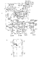
実施例1に係る液圧ブレーキシステムは、図2に示すブレーキ回路を含む。60はブレーキ操作部材としてのブレーキペダルであり、62はブレーキペダル60の操作により液圧を発生させるマスタシリンダである。64はポンプ装置65とアキュムレータ66とを含む動力式液圧源である。液圧ブレーキ40,50は、ブレーキシリンダ42,52の液圧により作動させられ、車輪の回転を抑制するものであり、本実施例においては、ディスクブレーキである。なお、液圧ブレーキ40,50は、ドラムブレーキとすることができる。また、前輪2,4の液圧ブレーキ40をディスクブレーキとし、後輪46,48の液圧ブレーキ50をドラムブレーキとすることもできる。
マスタシリンダ62は、2つの加圧ピストン68,69を備えたタンデム式のものであり、加圧ピストン68,69のそれぞれの前方が加圧室70,72とされる。本実施例においては、加圧室70,72がそれぞれマニュアル式液圧源に該当する。また、加圧室72,70には、それぞれ、マニュアル通路としてのマスタ通路74,76を介して、左前輪2の液圧ブレーキ40FLのブレーキシリンダ42FL、右前輪4の液圧ブレーキ40FRのブレーキシリンダ42FRが接続される。また、加圧室70,72は、加圧ピストン68,69が後退端に達した場合に、それぞれ、リザーバ78に連通させられる。リザーバ78の内部は、作動液を収容する複数の収容室80,82,84に仕切られている。収容室80,82は、それぞれ、加圧室70,72に対応して設けられ、収容室84はポンプ装置65に対応して設けられたものである。
The hydraulic brake system according to the first embodiment includes a brake circuit shown in FIG. Reference numeral 60 denotes a brake pedal as a brake operation member, and reference numeral 62 denotes a master cylinder that generates hydraulic pressure by operating the brake pedal 60. A power hydraulic pressure source 64 includes a pump device 65 and an accumulator 66. The hydraulic brakes 40 and 50 are actuated by the hydraulic pressure of the brake cylinders 42 and 52 to suppress the rotation of the wheels. In the present embodiment, the hydraulic brakes 40 and 50 are disc brakes. The hydraulic brakes 40 and 50 can be drum brakes. Alternatively, the hydraulic brake 40 for the front wheels 2 and 4 can be a disc brake, and the hydraulic brake 50 for the rear wheels 46 and 48 can be a drum brake.
The master cylinder 62 is of a tandem type having two pressure pistons 68 and 69, and the pressure chambers 70 and 72 are in front of the pressure pistons 68 and 69, respectively. In this embodiment, the pressurizing chambers 70 and 72 correspond to manual hydraulic pressure sources, respectively. The pressurizing chambers 72 and 70 are respectively connected to the brake cylinder 42FL of the hydraulic brake 40FL of the left front wheel 2 and the brake cylinder of the hydraulic brake 40FR of the right front wheel 4 via master passages 74 and 76 as manual passages. 42FR is connected. The pressurizing chambers 70 and 72 are communicated with the reservoir 78 when the pressurizing pistons 68 and 69 reach the retracted end, respectively. The interior of the reservoir 78 is partitioned into a plurality of storage chambers 80, 82, and 84 that store hydraulic fluid. The accommodating chambers 80 and 82 are provided corresponding to the pressurizing chambers 70 and 72, respectively, and the accommodating chamber 84 is provided corresponding to the pump device 65.

動力式液圧源64において、ポンプ装置65は、ポンプ90およびポンプモータ92を含み、ポンプ90によりリザーバ78の収容室84から作動液が汲み上げられて吐出されて、アキュムレータ66に蓄えられる。ポンプモータ92は、アキュムレータ66に蓄えられた作動液の圧力が予め定められた設定範囲内にあるように制御される。また、リリーフ弁93により、ポンプ90の吐出圧が過大になることが防止される。   In the motive power hydraulic pressure source 64, the pump device 65 includes a pump 90 and a pump motor 92, and the hydraulic fluid is pumped up from the storage chamber 84 of the reservoir 78 by the pump 90, and is stored in the accumulator 66. The pump motor 92 is controlled so that the pressure of the hydraulic fluid stored in the accumulator 66 is within a predetermined setting range. Further, the relief valve 93 prevents the discharge pressure of the pump 90 from becoming excessive.

動力式液圧源64とマスタシリンダ62とブレーキシリンダ42,52との間には増圧装置としてのメカ式増圧装置96が設けられる。メカ式増圧装置96は、可動部としてのメカ式可動部98と、入力側逆止弁99と、高圧側逆止弁100とを含む。メカ式可動部98は、ハウジング102と、ハウジング102に液密かつ摺動可能に嵌合された段付きピストン104とを含み、段付きピストン104の大径側に大径側室110が設けられ、小径側に小径側室112が設けられる。大径側室110には加圧室72が接続されるのであり、本実施例においては、加圧室72が増圧装置接続マニュアル式液圧源(1つのマニュアル式液圧源)に対応する。小径側室112には、動力式液圧源64に接続された高圧室114が連通させられ、小径側室112と高圧室114との間に、高圧供給弁116が設けられる。高圧供給弁116は、ハウジング102に形成された弁座122と、弁座122に対して接近、離間可能に設けられた弁子120と、スプリング124とを含み、スプリング124の付勢力が、弁子120を弁座122に押し付ける向きに作用する。高圧供給弁116は常閉弁である。小径側室112には、弁子120に対向して開弁部材125が設けられ、開弁部材125と段付きピストン104との間にスプリング126が設けられる。スプリング126の付勢力は、開弁部材125と段付きピストン104とを互いに離間させる向きに作用する。開弁部材125は、高圧供給弁116の構成要素であると考えることもできる。   A mechanical pressure booster 96 as a pressure booster is provided between the power hydraulic pressure source 64, the master cylinder 62, and the brake cylinders 42 and 52. The mechanical pressure booster 96 includes a mechanical movable portion 98 as a movable portion, an input side check valve 99, and a high pressure side check valve 100. The mechanical movable portion 98 includes a housing 102 and a stepped piston 104 that is fluid-tight and slidably fitted to the housing 102. A large-diameter side chamber 110 is provided on the large-diameter side of the stepped piston 104. A small-diameter side chamber 112 is provided on the small-diameter side. The pressurizing chamber 72 is connected to the large-diameter side chamber 110. In the present embodiment, the pressurizing chamber 72 corresponds to a pressure-increasing device connection manual hydraulic pressure source (one manual hydraulic pressure source). A high pressure chamber 114 connected to the power hydraulic pressure source 64 is communicated with the small diameter side chamber 112, and a high pressure supply valve 116 is provided between the small diameter side chamber 112 and the high pressure chamber 114. The high-pressure supply valve 116 includes a valve seat 122 formed in the housing 102, a valve element 120 provided so as to be able to approach and separate from the valve seat 122, and a spring 124. This acts in a direction to press the child 120 against the valve seat 122. The high pressure supply valve 116 is a normally closed valve. In the small diameter side chamber 112, a valve opening member 125 is provided so as to face the valve element 120, and a spring 126 is provided between the valve opening member 125 and the stepped piston 104. The biasing force of the spring 126 acts in a direction to separate the valve opening member 125 and the stepped piston 104 from each other. The valve opening member 125 can also be considered as a component of the high pressure supply valve 116.

段付きピストン104の段部とハウジング102との間には、スプリング128(リターンスプリング)が設けられ、段付きピストン104を後退方向に付勢する。なお、段付きピストン104とハウジング102との間には図示しないストッパが設けられ、段付きピストン104の前進端位置を規制する。また、段付きピストン104の内部には、大径側室110と小径側室112とを連通させるピストン内連通路129が形成され、ピストン内連通路129の途中にピストン内逆止弁130が設けられる。ピストン内逆止弁130は、大径側室110から小径側室112へ向かう作動液の流れを阻止し、小径側室112から大径側室110へ向かう作動液の流れを許容する。   A spring 128 (return spring) is provided between the step portion of the stepped piston 104 and the housing 102 to urge the stepped piston 104 in the backward direction. A stopper (not shown) is provided between the stepped piston 104 and the housing 102 to restrict the forward end position of the stepped piston 104. Further, in the stepped piston 104, an in-piston communication passage 129 that connects the large-diameter side chamber 110 and the small-diameter side chamber 112 is formed, and an in-piston check valve 130 is provided in the middle of the in-piston communication passage 129. The piston check valve 130 blocks the flow of hydraulic fluid from the large-diameter side chamber 110 toward the small-diameter side chamber 112 and allows the hydraulic fluid to flow from the small-diameter side chamber 112 toward the large-diameter side chamber 110.

高圧側逆止弁100は、高圧室114と動力式液圧源64とを接続する高圧供給通路132の途中に設けられる。高圧側逆止弁100は、動力式液圧源64の液圧が高圧室114の液圧より高い場合には、動力式液圧源64から高圧室114への作動液の流れを許容するが、動力式液圧源64の液圧が高圧室114の液圧以下の場合には閉状態にあり、双方向の流れを阻止する。そのため、仮に、電気系統の異常により、動力液圧源64の液圧が低くなっても、小径側室112の液圧の低下が防止される。   The high pressure check valve 100 is provided in the middle of the high pressure supply passage 132 that connects the high pressure chamber 114 and the power hydraulic pressure source 64. The high pressure side check valve 100 allows the flow of hydraulic fluid from the power hydraulic pressure source 64 to the high pressure chamber 114 when the hydraulic pressure of the power hydraulic pressure source 64 is higher than the hydraulic pressure of the high pressure chamber 114. When the hydraulic pressure of the motive power hydraulic pressure source 64 is equal to or lower than the hydraulic pressure of the high pressure chamber 114, the power supply pressure source 64 is in a closed state and prevents bidirectional flow. Therefore, even if the hydraulic pressure of the power hydraulic pressure source 64 decreases due to an abnormality in the electrical system, a decrease in the hydraulic pressure in the small-diameter side chamber 112 is prevented.

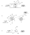
入力側逆止弁99は、マスタ通路74とメカ式可動部98の出力側(小径側室112でもよい)とを、メカ式可動部98をバイパスして接続する可動部バイパス通路としてのバイパス通路136の途中に設けられる。バイパス通路136は、マスタ通路74と共通通路94とを、メカ式可動部98をバイパスして接続する通路であると考えることもできる。入力側逆止弁99は、マスタ通路74からメカ式可動部98の出力側への作動液の流れを許容し、逆向きの流れを阻止するものであり、開弁圧が設定圧のものである。設定圧は、マスタリザーバ78とブレーキシリンダ42との間の高低差に起因する液圧差に基づいて決まる値である(マスタリザーバ78がブレーキシリンダ42より鉛直方向の上方にある)。設定圧は、高低差対応設定圧と称することができる。   The input-side check valve 99 is a bypass passage 136 serving as a movable portion bypass passage that connects the master passage 74 and the output side of the mechanical movable portion 98 (or the small-diameter side chamber 112) by bypassing the mechanical movable portion 98. It is provided in the middle. The bypass passage 136 can also be considered as a passage connecting the master passage 74 and the common passage 94 by bypassing the mechanical movable portion 98. The input-side check valve 99 allows the flow of hydraulic fluid from the master passage 74 to the output side of the mechanical movable unit 98 and blocks the reverse flow, and has a valve opening pressure of a set pressure. is there. The set pressure is a value determined based on a hydraulic pressure difference caused by a difference in height between the master reservoir 78 and the brake cylinder 42 (the master reservoir 78 is above the brake cylinder 42 in the vertical direction). The set pressure can be referred to as a height difference set pressure.

ブレーキペダル60の非操作状態において、マスタシリンダ62の加圧室72はマスタリザーバ78に連通させられ、ほぼ大気圧である。また、ブレーキシリンダ42の液圧もほぼ大気圧であるが、これらの間には、高低差に起因する液圧差がある。それに対して、入力側逆止弁99の開弁圧を高低差に起因する液圧差に基づいて決まる大きさとすれば、ブレーキペダル60の非操作状態におけるマスタリザーバ78からの作動液の流出を阻止することができるのであり、仮に、ブレーキシリンダ42の周辺に漏れがあったとしても、マスタリザーバ78からブレーキシリンダ42に向かう作動液の流れを阻止することができる。また、ブレーキペダル60が作用操作(液圧ブレーキ40,50が作用状態になるように行われる操作であり、通常は、踏み込み操作である)され、加圧室72の液圧が高くなると、入力側逆止弁99の前後の差圧(マスタシリンダ側の液圧から共通通路側の液圧を引いた値)は高低差対応設定圧より大きくなり、入力側逆止弁99は開状態に切り換えられる。それにより、マスタシリンダ62からブレーキシリンダへ向かう作動液の流れが許容される。   When the brake pedal 60 is not operated, the pressurizing chamber 72 of the master cylinder 62 is communicated with the master reservoir 78 and is at almost atmospheric pressure. Further, the hydraulic pressure of the brake cylinder 42 is almost atmospheric pressure, but there is a hydraulic pressure difference due to the difference in height between them. On the other hand, if the valve opening pressure of the input-side check valve 99 is determined based on the hydraulic pressure difference due to the height difference, the hydraulic fluid from the master reservoir 78 is prevented from flowing out when the brake pedal 60 is not operated. Therefore, even if there is a leak around the brake cylinder 42, the flow of hydraulic fluid from the master reservoir 78 toward the brake cylinder 42 can be prevented. Further, when the brake pedal 60 is operated (the operation is performed so that the hydraulic brakes 40 and 50 are in an applied state and is usually a stepping operation), and the hydraulic pressure in the pressurizing chamber 72 is increased, the input is performed. The differential pressure before and after the side check valve 99 (the value obtained by subtracting the fluid pressure on the common passage side from the fluid pressure on the master cylinder side) is larger than the set pressure corresponding to the elevation difference, and the input side check valve 99 is switched to the open state. It is done. Thereby, the flow of hydraulic fluid from the master cylinder 62 toward the brake cylinder is allowed.

入力側逆止弁99は、例えば、図4に示す構造を成したものとすることができる。例えば、図4(a)に示すように、カップシール式の逆止弁99xとしたり、図4(b)に示すように、ボール式の逆止弁99yとしたり、図4(c)に示すように、磁力式の逆止弁99zとしたりすること等ができる。   The input-side check valve 99 can have, for example, the structure shown in FIG. For example, as shown in FIG. 4 (a), a cup seal type check valve 99x is used, as shown in FIG. 4 (b), a ball type check valve 99y is used, or as shown in FIG. 4 (c). Thus, the magnetic check valve 99z can be used.

図4(a)において、逆止弁99xは、バイパス通路136に固定的に設けられたハウジング140と、ハウジング140に支持された環状のシール部材142とを含む。シール部材142はゴム等の弾性変形し易い材料により成形されたものであり、矢印Xの方向に撓み易く、逆方向に撓み難い形状を成したものである。本実施例においては、矢印Xの上流側にマスタ通路74が接続され、下流側に共通通路94が接続される。シール部材142は、前後の差圧(マスタ通路74の液圧から共通通路94の液圧を引いた値)が高低差対応設定圧以下である場合には撓むことがない。逆止弁99xは閉状態にあり、マスタリザーバ78からの作動液の流出が阻止される。前後の差圧が高低差対応設定圧より大きくなるとシール部材142が撓む。逆止弁99xは開状態に切り換えられ、マスタシリンダ62からの流出が許容される。なお、逆向き、すなわち、共通通路94からマスタ通路74へ向かう作動液の流れは阻止される。   4A, the check valve 99x includes a housing 140 fixedly provided in the bypass passage 136, and an annular seal member 142 supported by the housing 140. The seal member 142 is formed of a material that is easily elastically deformed, such as rubber, and has a shape that is easily bent in the direction of the arrow X and hardly bent in the opposite direction. In the present embodiment, the master passage 74 is connected to the upstream side of the arrow X, and the common passage 94 is connected to the downstream side. The seal member 142 does not bend when the differential pressure before and after (the value obtained by subtracting the hydraulic pressure of the common passage 94 from the hydraulic pressure of the master passage 74) is equal to or lower than the set pressure corresponding to the elevation difference. The check valve 99x is in a closed state, and the outflow of hydraulic fluid from the master reservoir 78 is prevented. When the front-rear differential pressure becomes larger than the height difference setting pressure, the seal member 142 is bent. The check valve 99x is switched to the open state, and the outflow from the master cylinder 62 is allowed. Note that the flow of hydraulic fluid in the reverse direction, that is, from the common passage 94 toward the master passage 74 is blocked.

逆止弁99yは、図4(b)-(i)が示すように、(a)ハウジング142と、(b)ハウジング142に形成された弁座143と、(c)弁座143に対して接近・離間可能な弁子144とを含むシーティング弁である。逆止弁99yにおいて、弁子144が球状を成したものであり、スプリングが設けられていない。また、図4(b)-(ii)に示すように、ハウジング142の弁座143が設けられた側との反対側には、抜け止め部145が設けられる。本実施例において逆止弁99yは、図4(b)-(i)に示すように、逆止弁99yの軸線Lが水平線Hに対して角度θだけ傾いた姿勢で配設される。また、弁子144に作用する重力G(=mg)の軸線方向の成分Ga(=mgsinθ)の下流側にマスタ通路74が接続され、上流側に共通通路94が接続される。   As shown in FIGS. 4B to 4I, the check valve 99y includes (a) a housing 142, (b) a valve seat 143 formed on the housing 142, and (c) a valve seat 143. It is a seating valve including a valve element 144 that can be approached and separated. In the check valve 99y, the valve element 144 has a spherical shape and no spring is provided. Further, as shown in FIGS. 4B to 4I, a retaining portion 145 is provided on the opposite side of the housing 142 from the side on which the valve seat 143 is provided. In this embodiment, the check valve 99y is disposed in a posture in which the axis L of the check valve 99y is inclined by an angle θ with respect to the horizontal line H, as shown in FIGS. The master passage 74 is connected to the downstream side of the axial component Ga (= mgsin θ) of the gravity G (= mg) acting on the valve element 144, and the common passage 94 is connected to the upstream side.

逆止弁99yにおいて、前後の差圧(マスタリザーバ78の液圧から小径側室112の液圧を引いた値)が、成分Gaに対応する大きさ以下の場合には、弁子144は弁座143に着座した状態にある。逆止弁99yは閉状態にあり、マスタリザーバ78から増圧装置98の出力側への作動液の流れは阻止される。前後の差圧が、成分Gaに対応する大きさより大きくなると、弁子144が弁座143から離間させられ、逆止弁99yが開状態とされ、マスタ通路74から共通通路94へ向かう作動液の流れが許容される。この場合に、抜け止め部145が設けられるため、弁子144が逆止弁99yから抜け出すことが防止される。また、共通通路94からマスタ通路74に向かう作動液の流れが生じると、吸引力が作用し、弁子144は弁座143に向かって移動させられ、着座させられる。換言すれば、成分Gaが高低差対応設定圧に対応する力となる姿勢で(角度θだけ傾いた姿勢で)逆止弁99yが設けられる。   In the check valve 99y, when the differential pressure before and after (the value obtained by subtracting the hydraulic pressure of the small-diameter side chamber 112 from the hydraulic pressure of the master reservoir 78) is equal to or smaller than the magnitude corresponding to the component Ga, the valve element 144 is 143 is in a seated state. The check valve 99y is closed, and the flow of hydraulic fluid from the master reservoir 78 to the output side of the pressure increasing device 98 is blocked. When the front-rear differential pressure becomes larger than the magnitude corresponding to the component Ga, the valve element 144 is separated from the valve seat 143, the check valve 99y is opened, and the working fluid from the master passage 74 toward the common passage 94 is opened. Flow is allowed. In this case, since the retaining portion 145 is provided, the valve element 144 is prevented from coming out of the check valve 99y. Further, when a flow of hydraulic fluid from the common passage 94 toward the master passage 74 is generated, a suction force is applied, and the valve element 144 is moved toward the valve seat 143 and is seated. In other words, the check valve 99y is provided in a posture in which the component Ga becomes a force corresponding to the height difference setting pressure (in a posture inclined by the angle θ).

図4(c)において、逆止弁99zは、弁子146と弁座147とを含むものであるが、スプリングを有していない。また、弁子146,弁座147のうち少なくとも一方は強磁性材料から製造された永久磁石であり、磁力によって互いに接近するようにされている。弁子146と弁座147との間に作用する磁力(吸引力)は、高低差対応設定圧に対応する大きさとされる。磁力に対向する方向に、マスタ通路74の液圧と共通通路94の液圧との差圧が作用するように、すなわち、矢印Zの上流側にマスタ通路74が接続され、反対側に共通通路94が接続される。前後の差圧が高低差対応設定圧以下である場合には、逆止弁99zは閉状態にあり、マスタリザーバ78からの作動液の流出が阻止される。前後の差圧が、高低差対応設定圧より大きくなると、弁子146が磁力に抗して弁座147から離間し、逆止弁99zが開状態に切り換えられる。それにより、マスタ通路74から共通通路96に向かう作動液の流れが許容される。なお、逆止弁99zにおいても、図示を省略する抜け止め部を設けることができる。
本実施例においては、バイパス通路136,ピストン内連通路129により増圧装置内連通路が構成され、入力側逆止弁99x,99y,99z等により第1逆止弁が構成され、ピストン内逆止弁130により第2逆止弁が構成される。
In FIG. 4C, the check valve 99z includes a valve element 146 and a valve seat 147, but does not have a spring. Further, at least one of the valve element 146 and the valve seat 147 is a permanent magnet made of a ferromagnetic material, and is brought close to each other by a magnetic force. The magnetic force (attraction force) acting between the valve element 146 and the valve seat 147 has a magnitude corresponding to the height difference setting pressure. The master passage 74 is connected to the upstream side of the arrow Z so that a differential pressure between the hydraulic pressure of the master passage 74 and the hydraulic pressure of the common passage 94 acts in the direction opposite to the magnetic force, that is, the common passage on the opposite side. 94 is connected. When the front-rear differential pressure is equal to or lower than the set pressure corresponding to the height difference, the check valve 99z is in a closed state, and the outflow of hydraulic fluid from the master reservoir 78 is prevented. When the front-rear differential pressure becomes larger than the height difference setting pressure, the valve element 146 moves away from the valve seat 147 against the magnetic force, and the check valve 99z is switched to the open state. Thereby, the flow of hydraulic fluid from the master passage 74 toward the common passage 96 is allowed. In the check valve 99z, a retaining portion (not shown) can be provided.
In this embodiment, the bypass passage 136 and the piston internal passage 129 constitute the pressure booster internal passage, the input side check valves 99x, 99y, 99z, etc. constitute the first check valve, and the piston internal reverse passage. A stop valve 130 constitutes a second check valve.

なお、マスタ通路74とメカ式増圧装置96との間には、入力側遮断弁148が設けられる。入力側遮断弁148は、ソレノイドのコイルに電流(以下、ソレノイドに電流と略称する)が供給されない場合に開状態にある常開の電磁開閉弁である。   An input side shut-off valve 148 is provided between the master passage 74 and the mechanical pressure booster 96. The input side shut-off valve 148 is a normally open electromagnetic on-off valve that is open when no current is supplied to the solenoid coil (hereinafter abbreviated as current to the solenoid).

一方、左右前輪2,4のブレーキシリンダ42FL,FR、左右後輪46,48のブレーキシリンダ52RL,RRは、それぞれ、ブレーキ側通路、個別ブレーキ側通路としての個別通路150FL,FR,RL,RRを介して共通通路94に接続される。個別通路150FL,FR,RL,RRには、それぞれ、保持弁(SHij:i=F,R、j=L,R)153FL,FR,RL,RRが設けられるとともに、ブレーキシリンダ42FL,FR、52RL,52RRとリザーバ78との間には、それぞれ、減圧弁(SRij:i=F,R、j=L,R)156FL,FR,RL,RRが設けられる。本実施例においては、左右前輪2,4に対応して設けられた保持弁153FL,FRが、ソレノイドに電流が供給されない場合に開状態にある常開の電磁開閉弁であり、左右後輪46,48に対応して設けられた保持弁153RL,RRがソレノイドに電流が供給されない場合に閉状態にある常閉の電磁開閉弁である。また、左右前輪2,4に対応して設けられた減圧弁156FL,FRが、ソレノイドに電流が供給されない場合に閉状態にある常閉の電磁開閉弁であり、左右後輪46,48に対応して設けられた減圧弁156RL,RRがソレノイドに電流が供給されない場合に開状態にある常開の電磁開閉弁である。   On the other hand, the brake cylinders 42FL and FR of the left and right front wheels 2 and 4 and the brake cylinders 52RL and RR of the left and right rear wheels 46 and 48 have individual passages 150FL, FR, RL, and RR as the brake side passage and the individual brake side passage, respectively. To the common passage 94. The individual passages 150FL, FR, RL, RR are provided with holding valves (SHij: i = F, R, j = L, R) 153FL, FR, RL, RR, and brake cylinders 42FL, FR, 52RL, respectively. , 52RR and the reservoir 78 are provided with pressure reducing valves (SRij: i = F, R, j = L, R) 156FL, FR, RL, RR, respectively. In this embodiment, the holding valves 153FL and FR provided corresponding to the left and right front wheels 2 and 4 are normally open electromagnetic on-off valves that are open when no current is supplied to the solenoid. , 48 are normally closed electromagnetic on-off valves that are closed when no current is supplied to the solenoids. Further, the pressure reducing valves 156FL, FR provided corresponding to the left and right front wheels 2, 4 are normally closed electromagnetic on-off valves that are closed when no current is supplied to the solenoid, and correspond to the left and right rear wheels 46, 48. The pressure reducing valves 156RL and RR provided in this manner are normally open electromagnetic on-off valves that are open when no current is supplied to the solenoid.

共通通路94には、ブレーキシリンダ42,52に加えて、動力式液圧源64、メカ式増圧装置96も接続される。動力式液圧源64は、動力液圧通路170を介して共通通路94に接続される。動力液圧通路170に増圧リニア制御弁(SLA)172が設けられる。増圧リニア制御弁172は、ソレノイドに電流が供給されない場合に閉状態にある常閉の電磁開閉弁であり、ソレノイドへの供給電流の大きさの連続的な制御により、共通通路94の液圧の大きさを連続的に制御可能なものである。   In addition to the brake cylinders 42 and 52, a power hydraulic pressure source 64 and a mechanical pressure booster 96 are connected to the common passage 94. The power hydraulic pressure source 64 is connected to the common passage 94 via the power hydraulic pressure passage 170. The power hydraulic pressure passage 170 is provided with a pressure-increasing linear control valve (SLA) 172. The pressure-increasing linear control valve 172 is a normally closed electromagnetic on-off valve that is closed when no current is supplied to the solenoid, and the hydraulic pressure in the common passage 94 is controlled by continuously controlling the magnitude of the current supplied to the solenoid. Can be continuously controlled.

図3に示すように、増圧リニア制御弁172は、弁子180と弁座182とを含むシーティング弁と、スプリング184と、ソレノイド(コイルとプランジャとを含む)186とを含み、スプリング184の付勢力F2は、弁子180を弁座182に接近させる向きに作用し、ソレノイド186に電流が供給されることにより電磁駆動力F1が弁子180を弁座182から離間させる向きに作用する。また、増圧リニア制御弁172において、動力式液圧源64と共通通路94との差圧に応じた差圧作用力F3が弁子180を弁座182から離間させる向きに作用する(F1+F3:F2)。ソレノイド186への供給電流の制御により、差圧作用力F3が制御され、動力液圧通路170の液圧が制御される。また、増圧リニア制御弁172は、動力式液圧源64の出力液圧を制御する出力液圧制御弁と称することもできる。なお、共通通路94の減圧制御を行う場合には、保持弁153の開状態において、少なくとも1つの減圧弁156が開閉させられる。本実施例においては、増圧リニア制御弁172、減圧弁156のうちの少なくとも1つ等により動力液圧制御装置が構成される。   As shown in FIG. 3, the pressure-increasing linear control valve 172 includes a seating valve including a valve element 180 and a valve seat 182, a spring 184, and a solenoid (including a coil and a plunger) 186. The urging force F <b> 2 acts in a direction in which the valve element 180 approaches the valve seat 182, and an electromagnetic driving force F <b> 1 acts in a direction in which the valve element 180 is separated from the valve seat 182 when current is supplied to the solenoid 186. Further, in the pressure-increasing linear control valve 172, a differential pressure acting force F3 corresponding to the differential pressure between the power hydraulic pressure source 64 and the common passage 94 acts in a direction to separate the valve element 180 from the valve seat 182 (F1 + F3: F2). By controlling the current supplied to the solenoid 186, the differential pressure acting force F3 is controlled, and the hydraulic pressure in the power hydraulic pressure passage 170 is controlled. The pressure-increasing linear control valve 172 can also be referred to as an output hydraulic pressure control valve that controls the output hydraulic pressure of the power hydraulic pressure source 64. Note that, when the pressure reduction control of the common passage 94 is performed, at least one pressure reduction valve 156 is opened and closed when the holding valve 153 is open. In the present embodiment, the power hydraulic pressure control device is configured by at least one of the pressure-increasing linear control valve 172 and the pressure-reducing valve 156.

メカ式増圧装置96はサーボ圧通路190を介して共通通路94に接続される。サーボ圧通路190には、増圧装置遮断弁としての出力側遮断弁(SREG)192が設けられる。出力側遮断弁192はソレノイドに電流が供給されない場合に開状態にある常開の電磁開閉弁である。   The mechanical pressure booster 96 is connected to the common passage 94 via the servo pressure passage 190. The servo pressure passage 190 is provided with an output side cutoff valve (SREG) 192 as a pressure booster cutoff valve. The output-side shut-off valve 192 is a normally-open electromagnetic on-off valve that is open when no current is supplied to the solenoid.

一方、マスタ通路74,76が、それぞれ、左右前輪2,4の個別通路150FL,FRの保持弁153FL,FRの下流側に接続される。すなわち、マスタ通路74,76は、メカ式増圧装置96、共通通路94をバイパスして、加圧室72,70と、左右前輪2,4のブレーキシリンダ42とを直接接続するものである(マスタ通路74,76は直結型マニュアル通路と称することができる)。マスタ通路74,76の途中にそれぞれマニュアル遮断弁としてのマスタ遮断弁(SMCFL,FR)194FL,FRが設けられる。マスタ遮断弁194FL,FRはソレノイドに電流が供給されない場合に閉状態にある常閉の電磁開閉弁である。さらに、マスタ通路74には、ストロークシミュレータ200がシミュレータ制御弁202を介して接続される。シミュレータ制御弁202は常閉の電磁開閉弁である。   On the other hand, the master passages 74 and 76 are connected to the downstream sides of the holding valves 153FL and FR of the individual passages 150FL and FR of the left and right front wheels 2 and 4, respectively. That is, the master passages 74 and 76 bypass the mechanical pressure intensifier 96 and the common passage 94, and directly connect the pressurizing chambers 72 and 70 to the brake cylinders 42 of the left and right front wheels 2 and 4 ( The master passages 74 and 76 can be called direct connection type manual passages). Master cutoff valves (SMCFL, FR) 194FL, FR as manual cutoff valves are provided in the middle of the master passages 74, 76, respectively. The master shut-off valves 194FL and FR are normally closed electromagnetic on-off valves that are closed when no current is supplied to the solenoid. Further, the stroke simulator 200 is connected to the master passage 74 via a simulator control valve 202. The simulator control valve 202 is a normally closed electromagnetic on-off valve.

以上のように、本実施例においては、ポンプ装置65,増圧リニア制御弁172,マスタ遮断弁194,保持弁153,減圧弁156,入力側遮断弁148,出力側遮断弁192等により液圧制御部54が構成される。液圧制御部54はブレーキECU56の指令に基づいて制御される。ブレーキECU56は、図1に示すように、実行部、入出力部、記憶部等を含むコンピュータを主体とするものであり、入出力部には、ブレーキスイッチ218,ストロークセンサ220,マスタシリンダ圧センサ222,アキュムレータ圧センサ224,ブレーキシリンダ圧センサ226,レベルウォーニング228,車輪速度センサ230、イグニッションスイッチ234等が接続されるとともに液圧制御部54等が接続される。   As described above, in this embodiment, the hydraulic pressure is increased by the pump device 65, the pressure-increasing linear control valve 172, the master cutoff valve 194, the holding valve 153, the pressure reducing valve 156, the input side cutoff valve 148, the output side cutoff valve 192, and the like. A control unit 54 is configured. The hydraulic pressure control unit 54 is controlled based on a command from the brake ECU 56. As shown in FIG. 1, the brake ECU 56 mainly includes a computer including an execution unit, an input / output unit, a storage unit, and the like. The input / output unit includes a brake switch 218, a stroke sensor 220, a master cylinder pressure sensor. 222, an accumulator pressure sensor 224, a brake cylinder pressure sensor 226, a level warning 228, a wheel speed sensor 230, an ignition switch 234, and the like, and a hydraulic pressure control unit 54 and the like are connected.

ブレーキスイッチ218は、ブレーキペダル60が操作されるとOFFからONになるスイッチである。
ストロークセンサ220は、ブレーキペダル60の操作ストローク(STK)を検出するものであり、本実施例においては、2つのセンサが設けられ、同様に、ブレーキペダル60の操作ストロークが検出される。このように、ストロークセンサ220が2つ設けられるため、一方が故障しても他方により操作ストロークを検出することができる。
マスタシリンダ圧センサ222は、マスタシリンダ62の加圧室72の液圧(PMCFL)を検出するものであり、本実施例においては、マスタ通路74に設けられる。
The brake switch 218 is a switch that turns from OFF to ON when the brake pedal 60 is operated.
The stroke sensor 220 detects an operation stroke (STK) of the brake pedal 60. In this embodiment, two sensors are provided, and similarly, an operation stroke of the brake pedal 60 is detected. Thus, since two stroke sensors 220 are provided, even if one breaks down, the operation stroke can be detected by the other.
The master cylinder pressure sensor 222 detects the hydraulic pressure (PMCFL) in the pressurizing chamber 72 of the master cylinder 62, and is provided in the master passage 74 in this embodiment.

アキュムレータ圧センサ224は、アキュムレータ66に蓄えられている作動液の圧力(PACC)を検出するものである。
ブレーキシリンダ圧センサ226は、ブレーキシリンダ42,52の液圧(PWC)を検出するものであり、共通通路94に設けられる。保持弁153の開状態において、ブレーキシリンダ42,52と共通通路94とは連通させられるため、共通通路94の液圧をブレーキシリンダ42,52の液圧とすることができる。
レベルウォーニング228は、マスタリザーバ78に収容された作動液が予め定められた設定量以下になるとONとなるスイッチである。本実施例においては、3つの収容室80、82,84のいずれか1つに収容された作動液量が設定量以下になると、ONとなる。
車輪速度センサ230は、左右前輪2,4、左右後輪46,48に対応してそれぞれ設けられ、車輪の回転速度を検出する。また、4輪の回転速度に基づいて車両の走行速度が取得される。
イグニッションスイッチ(IGSW)234は、車両のメインスイッチである。
記憶部には、種々のプログラム、テーブル等が記憶されている。
The accumulator pressure sensor 224 detects the pressure (PACC) of the hydraulic fluid stored in the accumulator 66.
The brake cylinder pressure sensor 226 detects the hydraulic pressure (PWC) of the brake cylinders 42 and 52 and is provided in the common passage 94. When the holding valve 153 is in the open state, the brake cylinders 42 and 52 and the common passage 94 are communicated with each other, so that the hydraulic pressure in the common passage 94 can be made the hydraulic pressure in the brake cylinders 42 and 52.
The level warning 228 is a switch that is turned on when the hydraulic fluid stored in the master reservoir 78 is less than or equal to a predetermined set amount. In the present embodiment, when the amount of the hydraulic fluid stored in any one of the three storage chambers 80, 82, 84 becomes equal to or less than the set amount, it is turned ON.
Wheel speed sensors 230 are provided corresponding to the left and right front wheels 2, 4 and the left and right rear wheels 46, 48, respectively, and detect the rotational speed of the wheels. Further, the traveling speed of the vehicle is acquired based on the rotational speed of the four wheels.
The ignition switch (IGSW) 234 is a main switch of the vehicle.
Various programs, tables, and the like are stored in the storage unit.

<液圧ブレーキシステムにおける作動>
本実施例において、正常である場合、漏れの可能性がある場合、制御系が異常である場合の各々において、ブレーキシリンダ42,52への液圧の供給状態が制御される。
図5のフローチャートで表される供給状態制御プログラムは予め定められた設定時間毎に実行される。
ステップ1(以下、S1と略称する。他のステップについても同様とする)において、制動要求があるか否かが判定される。ブレーキスイッチ218がONである場合、あるいは、自動ブレーキを作動させる要求がある場合等には制動要求があるとされて、判定がYESとなる。自動ブレーキは、トラクション制御、ビークルスタビリティ制御、車間距離制御、衝突回避制御において作動させられる場合があり、これらの制御開始条件が満たされた場合に、制動要求があるとされることがある。
制動要求がある場合には、S2、3において、液漏れの可能性があるか否か、制御系が異常であるか否かの判定結果が読み込まれる。
<Operation in hydraulic brake system>
In the present embodiment, the supply state of the hydraulic pressure to the brake cylinders 42 and 52 is controlled in each of the case where there is a possibility of leakage, the possibility of leakage, and the case where the control system is abnormal.
The supply state control program represented by the flowchart of FIG. 5 is executed at predetermined time intervals.
In step 1 (hereinafter abbreviated as S1; the same applies to other steps), it is determined whether or not there is a braking request. When the brake switch 218 is ON, or when there is a request for operating the automatic brake, it is determined that there is a braking request, and the determination is YES. The automatic brake may be operated in traction control, vehicle stability control, inter-vehicle distance control, and collision avoidance control. When these control start conditions are satisfied, a braking request may be made.
When there is a braking request, in S2 and S3, a determination result as to whether there is a possibility of liquid leakage or whether the control system is abnormal is read.

液漏れの可能性の有無とは、液漏れの可能性の高低、液漏れの量の多少を問わない。そのため、液漏れの可能性が非常に低い場合、あるいは、漏れ量が非常に少ない場合であっても、液漏れでないと断定できない場合には可能性が有るとする。そのため、液漏れの可能性が有ると検出された場合であっても、液漏れが実際に生じていない場合がある{液漏れ以外の原因によって、後述する(b)〜(e)の条件が満たされる場合があり得る}。
例えば、(a)レベルウォーニングスイッチ228がONである場合、(b)ブレーキ操作が行われた場合において、ブレーキペダル60のストロークとマスタシリンダ62の液圧との間に予め定められた関係が成立する場合には液漏れがないとされるが、マスタシリンダ62の液圧がストロークに対して小さい場合には液漏れの可能性が有るとされる。また、(c)ポンプ92が予め定められた設定時間以上継続して作動してもアキュムレータ圧センサ224の検出値が液漏れ判定しきい値以上にならない場合、(d)回生協調制御が行われていない場合において、マスタシリンダ圧センサ222の検出値に対してブレーキシリンダ圧センサ226の検出値が小さい場合、(e)前回のブレーキ作動時に、液漏れの可能性が有ると検出された場合(左右前輪2,4のブレーキシリンダ42にマスタシリンダ62の液圧が供給され、左右後輪46,48のブレーキシリンダ52にポンプ圧が供給された場合)等には、液漏れの可能性が有るとされる。
The presence or absence of the possibility of liquid leakage does not matter whether the possibility of liquid leakage is high or low and the amount of liquid leakage. Therefore, there is a possibility that the possibility of liquid leakage is very low, or even if the amount of leakage is very small, it cannot be determined unless it is liquid leakage. Therefore, even if it is detected that there is a possibility of liquid leakage, the liquid leakage may not actually occur {the conditions (b) to (e) described later are caused by causes other than liquid leakage. May be met}.
For example, when (a) the level warning switch 228 is ON, (b) when a brake operation is performed, a predetermined relationship is established between the stroke of the brake pedal 60 and the hydraulic pressure of the master cylinder 62. In this case, it is assumed that there is no liquid leakage. However, if the hydraulic pressure in the master cylinder 62 is small relative to the stroke, there is a possibility of liquid leakage. Further, (c) when the detection value of the accumulator pressure sensor 224 does not exceed the liquid leakage determination threshold value even if the pump 92 continues to operate for a predetermined set time or longer, (d) regenerative cooperative control is performed. If the detected value of the brake cylinder pressure sensor 226 is smaller than the detected value of the master cylinder pressure sensor 222, (e) if it is detected that there is a possibility of liquid leakage during the previous brake operation ( In the case where the hydraulic pressure of the master cylinder 62 is supplied to the brake cylinders 42 of the left and right front wheels 2, 4 and the pump pressure is supplied to the brake cylinders 52 of the left and right rear wheels 46, 48), there is a possibility of liquid leakage. It is said.

制御系の異常とは、ブレーキシリンダ42,52の液圧あるいは共通通路94の液圧を、動力式液圧源64の液圧を利用して制御できない状態をいう。
例えば、(i)電磁開閉弁等を指令通りに作動させることができない場合{増圧リニア制御弁172等の電磁開閉弁(例えば、保持弁153,減圧弁156,マスタ遮断弁194,出力側遮断弁192等)において断線が生じている場合等}、(ii)ブレーキシリンダ42,52の液圧の制御に必要な検出値が得られない場合(正確に得られない場合も含む)[
各センサ(ブレーキスイッチ218,ストロークセンサ220、マスタシリンダ圧センサ222、アキュムレータ圧センサ224,ブレーキシリンダ圧センサ226,車輪速度センサ230等)において断線が生じている場合等]、(iii)各電磁開閉弁、センサ等に電力(電気エネルギ、電流と称することもできる)を供給できない場合(蓄電装置22等の電源の異常、あるいは、配線の断線が生じている場合等)、(iv)動力式液圧源64から高圧の作動液を供給できない場合{例えば、ポンプモータ92の異常、ポンプモータ92に電力を供給できない場合(電源の異常に起因する場合を含む)等}が該当する。
The abnormality of the control system means a state in which the hydraulic pressure of the brake cylinders 42 and 52 or the hydraulic pressure of the common passage 94 cannot be controlled using the hydraulic pressure of the power type hydraulic pressure source 64.
For example, (i) When an electromagnetic on-off valve or the like cannot be operated as commanded {an electromagnetic on-off valve such as a pressure increasing linear control valve 172 (for example, a holding valve 153, a pressure reducing valve 156, a master cutoff valve 194, an output side cutoff Valve 192 etc.) is disconnected, etc.}, (ii) when a detection value necessary for controlling the hydraulic pressure of the brake cylinders 42 and 52 cannot be obtained (including cases where it cannot be obtained accurately) [
Each sensor (brake switch 218, stroke sensor 220, master cylinder pressure sensor 222, accumulator pressure sensor 224, brake cylinder pressure sensor 226, wheel speed sensor 230, etc.) is disconnected, etc.], (iii) each electromagnetic open / close When power (also referred to as electrical energy or current) cannot be supplied to valves, sensors, etc. (such as when the power supply of the power storage device 22 or the like is broken or the wiring is broken), (iv) This corresponds to a case where high-pressure hydraulic fluid cannot be supplied from the pressure source 64 {for example, an abnormality of the pump motor 92, a case where electric power cannot be supplied to the pump motor 92 (including a case caused by an abnormality of the power source), etc.}.

S2,3のいずれの判定もNOであり、当該液圧ブレーキシステムが正常である場合(本実施例においては、制御系が正常で、かつ、液漏れの可能性が無いとされた場合)には、S4において、正常時制御が行われる。動力式液圧源64の出力液圧が増圧リニア制御弁172によって制御されて、その動力制御圧が共通通路94に供給され、ブレーキシリンダ42,52に供給される。
制御系が異常である場合には、S3の判定がYESとなり、S5において、すべてのバルブのソレノイドに電流が供給されなくなることにより、原位置に戻される。また、ポンプモータ92は停止状態に保たれる。
液漏れの可能性が有ると検出された場合には、S2の判定がNOとなり、S6において、左右前輪2,4のブレーキシリンダ42にマスタシリンダ62の液圧が供給され、左右後輪46,48のブレーキシリンダ52に動力式液圧源64の出力液圧が制御されて供給される。制御系の異常と液漏れの可能性との両方が生じることは稀であるため、液漏れの可能性が有るとされても制御系は正常であり、各バルブの制御、ポンプモータ92の駆動は可能であると考えられる。
また、本実施例においては、制御系が異常であるとされた場合、液漏れの可能性が有るとされた場合には自動ブレーキは作動させられないようにされている。
When both determinations of S2 and S3 are NO and the hydraulic brake system is normal (in this embodiment, the control system is normal and there is no possibility of liquid leakage). In S4, normal control is performed. The output hydraulic pressure of the power hydraulic pressure source 64 is controlled by the pressure-increasing linear control valve 172, and the power control pressure is supplied to the common passage 94 and supplied to the brake cylinders 42 and 52.
If the control system is abnormal, the determination in S3 is YES, and in S5, no current is supplied to the solenoids of all the valves, thereby returning the original position. Further, the pump motor 92 is kept in a stopped state.
If it is detected that there is a possibility of liquid leakage, the determination in S2 is NO, and in S6, the hydraulic pressure of the master cylinder 62 is supplied to the brake cylinders 42 of the left and right front wheels 2, 4, and the left and right rear wheels 46, The output hydraulic pressure of the power type hydraulic pressure source 64 is controlled and supplied to the 48 brake cylinders 52. Since it is rare that both the abnormality of the control system and the possibility of liquid leakage occur, the control system is normal even if there is a possibility of liquid leakage, the control of each valve, the drive of the pump motor 92 Is considered possible.
In the present embodiment, the automatic brake is not operated when the control system is abnormal or when there is a possibility of liquid leakage.

1)システムが正常な場合
図6に示すように、前後左右の4輪2,4,46,48のブレーキシリンダ42,52には、動力式液圧源64の液圧が制御されて(制御された液圧を動力制御圧と称する)供給されるのであり、原則として回生協調制御が行われる。
回生協調制御は、駆動輪2,4に加わる回生制動トルクと、駆動輪2,4と従動輪46,48との両方に加わる摩擦制動トルクとの和である総制動トルクが総要求制動トルクとなるように行われる制御である。
総要求制動トルクは、ストロークセンサ220,マスタシリンダ圧センサ222の検出値等に基づいて取得される場合(運転者が要求する制動トルク)、車両の走行状態に基づいて取得される場合(トラクション制御、ビークルスタビリティ制御において必要な制動トルク)等がある。そして、ハイブリッドECU58から供給された情報(電動モータ20の回転数等に基づいて決まる回生制動トルクの上限値である発電側上限値、蓄電装置22の充電容量等に基づいて決まる上限値である蓄電側上限値)と、上述の総要求制動トルク(要求値)とのうちの最小値が要求回生制動トルクとして決定され、この要求回生制動トルクを表す情報がハイブリッドECU58に供給される。
ハイブリッドECU58は要求回生制動トルクを表す情報をモータECU28に出力する。モータECU28は、電動モータ20によって左右前輪2,4に加えられる制動トルクが要求回生制動トルクとなるように、電力変換装置26に制御指令を出力する。電動モータ20は、電力変換装置26によって制御される。
電動モータ20の実際の回転数等の作動状態を表す情報がモータECU28からハイブリッドECU58に供給される。ハイブリッドECU58において、電動モータ20の実際の作動状態に基づいて実際に得られた実回生制動トルクが求められ、その実回生制動トルク値を表す情報をブレーキECU56に出力する。
ブレーキECU56は、総要求制動トルクから実回生制動トルクを引いた値等に基づいて要求液圧制動トルクを決定し、ブレーキシリンダ液圧が要求液圧制動トルクに対応する目標液圧に近づくように、増圧リニア制御弁172、減圧弁156等を制御する。
1) When the system is normal As shown in FIG. 6, the hydraulic pressure of the power hydraulic pressure source 64 is controlled in the brake cylinders 42, 52 of the front, rear, left and right four wheels 2, 4, 46, 48 (control). In principle, regenerative cooperative control is performed.
In the regenerative cooperative control, the total braking torque, which is the sum of the regenerative braking torque applied to the driving wheels 2 and 4 and the friction braking torque applied to both the driving wheels 2 and 4 and the driven wheels 46 and 48, is the total required braking torque. The control is performed as follows.
The total required braking torque is acquired based on detection values of the stroke sensor 220 and the master cylinder pressure sensor 222 (braking torque requested by the driver), or acquired based on the running state of the vehicle (traction control). Braking torque necessary for vehicle stability control). Then, the information supplied from the hybrid ECU 58 (the power generation side upper limit value that is the upper limit value of the regenerative braking torque determined based on the rotation speed of the electric motor 20, the power storage that is the upper limit value determined based on the charging capacity of the power storage device 22, etc. Side upper limit value) and the total required braking torque (requested value) described above are determined as the required regenerative braking torque, and information representing the required regenerative braking torque is supplied to the hybrid ECU 58.
Hybrid ECU 58 outputs information representing the required regenerative braking torque to motor ECU 28. The motor ECU 28 outputs a control command to the power converter 26 so that the braking torque applied to the left and right front wheels 2 and 4 by the electric motor 20 becomes the required regenerative braking torque. The electric motor 20 is controlled by the power converter 26.
Information representing the operating state such as the actual rotational speed of the electric motor 20 is supplied from the motor ECU 28 to the hybrid ECU 58. The hybrid ECU 58 obtains the actual regenerative braking torque actually obtained based on the actual operating state of the electric motor 20, and outputs information representing the actual regenerative braking torque value to the brake ECU 56.
The brake ECU 56 determines the required hydraulic braking torque based on a value obtained by subtracting the actual regenerative braking torque from the total required braking torque, so that the brake cylinder hydraulic pressure approaches the target hydraulic pressure corresponding to the required hydraulic braking torque. The pressure increasing linear control valve 172, the pressure reducing valve 156 and the like are controlled.

回生協調制御においては、原則として、前後左右の各輪2,4,46,48の保持弁153FL,FR,RL,RRがすべて開状態とされ、減圧弁156FL,FR,RL,RRがすべて閉状態とされる。また、マスタ遮断弁194FL,FRは閉状態とされ、シミュレータ制御弁202が開状態とされ、入力側遮断弁148が閉状態とされ、出力側遮断弁192が閉状態とされる。共通通路94がメカ式増圧装置96から遮断され、左右前輪2,4のブレーキシリンダ42FL、FRがマスタシリンダ62から遮断された状態で、増圧リニア制御弁172の制御により、動力式液圧源64の出力液圧が制御され、その動力制御圧が共通通路94に供給され、4輪のブレーキシリンダ42,52に共通に供給される。なお、共通通路94の液圧を減少させる場合には、減圧弁156FL,FR,RL,RRのうちの1つ以上が制御される。   In regenerative cooperative control, in principle, the holding valves 153FL, FR, RL, RR of the front, rear, left and right wheels 2, 4, 46, 48 are all opened, and the pressure reducing valves 156FL, FR, RL, RR are all closed. State. Further, the master cutoff valves 194FL and FR are closed, the simulator control valve 202 is opened, the input side cutoff valve 148 is closed, and the output side cutoff valve 192 is closed. With the common passage 94 cut off from the mechanical pressure booster 96 and the brake cylinders 42FL and FR of the left and right front wheels 2 and 4 cut off from the master cylinder 62, the hydraulic pressure is controlled by the pressure boost linear control valve 172. The output hydraulic pressure of the source 64 is controlled, and the power control pressure is supplied to the common passage 94 and supplied to the four-wheel brake cylinders 42 and 52 in common. Note that when the hydraulic pressure in the common passage 94 is decreased, one or more of the pressure reducing valves 156FL, FR, RL, and RR are controlled.

このように、本実施例においては、正常作動時に、入力側遮断弁148が閉状態とされる。
仮に、入力側遮断弁148が開状態にある場合を想定する。
出力側遮断弁192は閉状態にあるため、メカ式増圧装置96は非作動状態にあるのが原則である。しかし、高圧室114の容積と、小径側室112の容積と、大径側室110の容積との和がほぼ一定に保たれる範囲内で、段付きピストン104の前進は許容される。一方、シミュレータ制御弁202は開状態にあるため、マスタ通路74の液圧がストロークシミュレータ200の作動開始圧より大きくなると、ストロークシミュレータ200が作動させられるが、本実施例において、ストロークシミュレータ200の作動開始圧は、メカ式可動部98の作動開始圧より小さい。
ブレーキペダル60が作用操作され、マスタ通路74の液圧が、ストロークシミュレータ200の作動開始圧より大きくなると、ストロークシミュレータ200が作動させられ、ブレーキペダル60の前進が許容される。その後、メカ式可動部98の作動開始圧より大きくなると、段付きピストン104が前進させられ、それにより、ブレーキペダル60の入り込みが生じるのであり、運転者は違和感を感じる。
それに対して、本実施例においては、入力側遮断弁148が閉状態とされる。その結果、ブレーキペダル60はストロークシミュレータ200の作動に伴って前進が許容される。急激な入り込みが抑制されるのであり、運転者の違和感を軽減することができる。
また、入力側遮断弁148を閉状態とすることにより、振動を軽減したり、作動音を軽減したりすること等ができる。
ストロークシミュレータ200の作動開始圧は、スプリングのセット荷重、ピストンとハウジングとの間の摩擦等の摺動抵抗等で決まる値であり、ピストンに作用する液圧が作動開始圧より大きくなると、ピストンの移動が許容される。作動開始圧は、スプリングのセット荷重、摩擦力等で決まる。
メカ式可動部98の作動開始圧も同様であり、スプリング126のセット荷重、段付きピストン104とハウジング102との間に作用する摩擦力等の摺動抵抗等で決まる値である。
Thus, in this embodiment, the input side shut-off valve 148 is closed during normal operation.
Assume that the input side shut-off valve 148 is in an open state.
Since the output side shut-off valve 192 is in a closed state, the mechanical pressure intensifier 96 is in principle inoperative. However, the stepped piston 104 is allowed to advance within a range in which the sum of the volume of the high-pressure chamber 114, the volume of the small-diameter side chamber 112, and the volume of the large-diameter side chamber 110 is kept substantially constant. On the other hand, since the simulator control valve 202 is in the open state, the stroke simulator 200 is activated when the hydraulic pressure in the master passage 74 becomes larger than the operation start pressure of the stroke simulator 200. In this embodiment, the operation of the stroke simulator 200 is performed. The start pressure is smaller than the operation start pressure of the mechanical movable unit 98.
When the brake pedal 60 is operated and the hydraulic pressure in the master passage 74 becomes larger than the operation start pressure of the stroke simulator 200, the stroke simulator 200 is activated and the brake pedal 60 is allowed to advance. Thereafter, when the pressure exceeds the operation start pressure of the mechanical movable portion 98, the stepped piston 104 is moved forward, whereby the brake pedal 60 enters, and the driver feels uncomfortable.
On the other hand, in this embodiment, the input side shut-off valve 148 is closed. As a result, the brake pedal 60 is allowed to advance with the operation of the stroke simulator 200. Sudden entry is suppressed, and the driver's uncomfortable feeling can be reduced.
Further, by closing the input side shut-off valve 148, it is possible to reduce vibration, reduce operating noise, and the like.
The operation start pressure of the stroke simulator 200 is a value determined by a set load of the spring, a sliding resistance such as friction between the piston and the housing, and when the hydraulic pressure acting on the piston becomes larger than the operation start pressure, Movement is allowed. The operation start pressure is determined by the spring set load, frictional force, and the like.
The operation start pressure of the mechanical movable portion 98 is the same, and is a value determined by a set load of the spring 126, a sliding resistance such as a frictional force acting between the stepped piston 104 and the housing 102, and the like.

なお、この状態で、車輪2,4,46,48のスリップが過大となり、アンチロック制御開始条件が満たされると、保持弁153、減圧弁156が別個独立にそれぞれ開閉させられ、各ブレーキシリンダ42,52の液圧が制御される。前後左右の各輪2,4,46,48のスリップ状態が適正な状態とされる。
また、液圧ブレーキシステムが電気的駆動装置8を備えていない車両に搭載された場合等回生協調制御が行われない車両においては、システムが正常である場合に、総要求制動トルクと液圧制動トルクとが等しくなるように、増圧リニア制御弁172等が制御される。
なお、ブレーキECU56の液圧供給状態制御プログラムのS4を記憶する部分、実行する部分等により、第1入力側遮断弁制御装置、第2入力側遮断弁制御装置が構成される。また、これらは、動力制御圧供給部と称することもできる。
また、ブレーキECU56のS4を記憶する部分、実行する部分、動力式液圧源64,増圧リニア制御弁172,共通通路94,個別通路150、ブレーキシリンダ42,52等により動力液圧系が構成される。
In this state, when the slip of the wheels 2, 4, 46, 48 becomes excessive and the antilock control start condition is satisfied, the holding valve 153 and the pressure reducing valve 156 are opened and closed independently, and the brake cylinders 42 are opened and closed. , 52 is controlled. The slip state of the front, rear, left and right wheels 2, 4, 46, 48 is set to an appropriate state.
Further, when the hydraulic brake system is mounted on a vehicle that does not include the electric drive device 8, in a vehicle in which regenerative cooperative control is not performed, when the system is normal, the total required braking torque and the hydraulic braking are performed. The pressure-increasing linear control valve 172 and the like are controlled so that the torque becomes equal.
The first input side shut-off valve control device and the second input side shut-off valve control device are configured by a portion that stores S4 of the hydraulic pressure supply state control program of the brake ECU 56, a portion that executes the program, and the like. Moreover, these can also be called a power control pressure supply part.
Further, the part for storing S4 of the brake ECU 56, the part for executing, the power hydraulic pressure source 64, the pressure-increasing linear control valve 172, the common passage 94, the individual passage 150, the brake cylinders 42, 52, etc. constitute a power hydraulic system. Is done.

2)制御系が異常である場合
図7,8に示すように、各バルブは原位置に戻される。
増圧リニア制御弁172は、ソレノイド186に電流が供給されないことにより閉状態とされて、動力式液圧源64が共通通路94から遮断される。
また、マスタ遮断弁194は閉状態とされるため、ブレーキシリンダ42は、マスタシリンダ62から遮断される。
さらに、入力側遮断弁148、出力側遮断弁192は開状態とされるため、メカ式増圧装置96が、マスタ通路74,共通通路94に連通させられる。
さらに、保持弁153RL,RRは閉状態にあり、保持弁153FL,FRは開状態にあるため、共通通路94に左右前輪2,4のブレーキシリンダ42FL,FRが連通させられ、左右後輪46,48のブレーキシリンダ52RL,RRが遮断される。
このように、制御系の異常時に、左右前輪2,4のブレーキシリンダ42FL,FRが作動させられるため、車両の重心が左右方向のほぼ中心にある場合に、ヨーモーメントが生じ難くすることができる。
2) When the control system is abnormal As shown in FIGS. 7 and 8, each valve is returned to its original position.
The pressure-increasing linear control valve 172 is closed when no current is supplied to the solenoid 186, and the power hydraulic pressure source 64 is shut off from the common passage 94.
In addition, since the master shut-off valve 194 is closed, the brake cylinder 42 is shut off from the master cylinder 62.
Further, since the input side shut-off valve 148 and the output side shut-off valve 192 are opened, the mechanical pressure booster 96 is communicated with the master passage 74 and the common passage 94.
Further, since the holding valves 153RL and RR are in the closed state and the holding valves 153FL and FR are in the open state, the brake cylinders 42FL and FR of the left and right front wheels 2 and 4 are communicated with the common passage 94, and the left and right rear wheels 46, The 48 brake cylinders 52RL and RR are shut off.
As described above, when the control system is abnormal, the brake cylinders 42FL and FR of the left and right front wheels 2 and 4 are actuated, so that the yaw moment can be hardly generated when the center of gravity of the vehicle is substantially at the center in the left and right direction. .

2−1)大径側室110の液圧がメカ式可動部98の作動開始圧以下の場合
図7に示すように、大径側室110の液圧が、メカ式可動部98の作動開始圧以下の場合には、加圧室72の液圧(マニュアル液圧としてのマスタ液圧と称する)は、マスタ通路74,バイパス通路136、サーボ圧通路190を経て共通通路94に供給され、左右前輪2,4のブレーキシリンダ42に供給される。
入力側逆止弁99の開弁圧は非常に小さいため、ブレーキペダル60の操作に伴って速やかにブレーキシリンダ42に作動液を供給することが可能となり、液圧ブレーキ40の効き遅れを小さくすることができる。
2-1) When the hydraulic pressure in the large-diameter side chamber 110 is equal to or less than the operation start pressure of the mechanical movable unit 98 As shown in FIG. In this case, the hydraulic pressure in the pressurizing chamber 72 (referred to as a master hydraulic pressure as a manual hydraulic pressure) is supplied to the common passage 94 via the master passage 74, the bypass passage 136, and the servo pressure passage 190, and the left and right front wheels 2 are supplied. , 4 are supplied to the brake cylinder 42.
Since the valve opening pressure of the input-side check valve 99 is very small, it becomes possible to quickly supply the hydraulic fluid to the brake cylinder 42 in accordance with the operation of the brake pedal 60, and to reduce the delay in the effect of the hydraulic brake 40. be able to.

2−2)大径側室110の液圧がメカ式可動部98の作動開始圧より大きい場合
2−2−1)アキュムレータ66に蓄えられた作動液の液圧が作用許可圧より大きい場合
ポンプ装置65の作動が停止させられても、アキュムレータ66に蓄えられた作動液の液圧が設定圧より大きい場合には、メカ式可動部98の作動が許可される。設定圧は、メカ式可能部98を作動させ得る大きさであり、換言すれば、メカ式可動部98の高圧室114に液圧を供給し得る大きさであり、高圧室114(小径側室112)の液圧より大きい値であると考えることができる。設定圧を作動許可圧と称することができる。
図8の実線が示すように、大径側室110の液圧によって段付きピストン104が前進させられ、開弁部材125に当接し、高圧供給弁116が開状態に切り換えられる。小径側室112が大径側室110から遮断され、アキュムレータ66から高圧側逆止弁100を経て高圧室114に高圧の作動液が供給され、小径側室112に供給される。小径側室112の液圧は、マスタシリンダ62の液圧より高くされ、開状態にある出力側遮断弁192を経て共通通路94に供給され、保持弁153FL,FRを経て左右前輪2,4のブレーキシリンダ42FL,42RRに供給される。
小径側室112の液圧Poutは、仮に、作動開始圧が0であるとした場合に、マスタシリンダ62の液圧(大径側室110の液圧)Pinに、段付きピストン104の大径部側の受圧面積Sinと小径部側の受圧面積Soutとの比率(Sin/Sout)を掛けた値
Pout=Pin・(Sin/Sout)
となる。この液圧Poutをサーボ圧と称する。また、このことから、小径側室112は制御圧室と称することができる。
なお、メカ式増圧装置96は加圧室72の液圧により作動させられるため、広義のマニュアル液圧源であると考えることができる。本実施例においては、加圧室72が第1マニュアル式液圧源としての増圧装置接続マニュアル式液圧源に対応し、メカ式増圧装置96が第2マニュアル式液圧源に対応する。
2-2) When the hydraulic pressure in the large-diameter side chamber 110 is higher than the operation start pressure of the mechanical movable unit 98 2-2-1) When the hydraulic pressure of the hydraulic fluid stored in the accumulator 66 is higher than the allowable pressure Even when the operation of 65 is stopped, if the hydraulic pressure of the hydraulic fluid stored in the accumulator 66 is higher than the set pressure, the operation of the mechanical movable unit 98 is permitted. The set pressure is such a size that the mechanical type capable portion 98 can be operated, in other words, a size capable of supplying the hydraulic pressure to the high pressure chamber 114 of the mechanical type movable portion 98, and the high pressure chamber 114 (the small diameter side chamber 112). ) Can be considered to be larger than the hydraulic pressure. The set pressure can be referred to as an operation permission pressure.
As indicated by the solid line in FIG. 8, the stepped piston 104 is advanced by the hydraulic pressure in the large-diameter side chamber 110, contacts the valve opening member 125, and the high-pressure supply valve 116 is switched to the open state. The small-diameter side chamber 112 is shut off from the large-diameter side chamber 110, and high-pressure hydraulic fluid is supplied from the accumulator 66 to the high-pressure chamber 114 through the high-pressure side check valve 100 and then supplied to the small-diameter side chamber 112. The hydraulic pressure in the small-diameter side chamber 112 is made higher than the hydraulic pressure in the master cylinder 62, supplied to the common passage 94 through the output-side shut-off valve 192 in the open state, and brakes for the left and right front wheels 2 and 4 through the holding valves 153FL and FR. It is supplied to the cylinders 42FL and 42RR.
The hydraulic pressure Pout of the small-diameter side chamber 112 is assumed to be equal to the hydraulic pressure of the master cylinder 62 (the hydraulic pressure of the large-diameter side chamber 110) Pin and the large-diameter portion side of the stepped piston 104, assuming that the operation start pressure is zero. A value Pout = Pin · (Sin / Sout) obtained by multiplying the ratio (Sin / Sout) of the pressure receiving area Sin and the pressure receiving area Sout on the small diameter portion side
It becomes. This hydraulic pressure Pout is referred to as servo pressure. From this, the small-diameter side chamber 112 can be called a control pressure chamber.
The mechanical pressure increasing device 96 is actuated by the hydraulic pressure in the pressurizing chamber 72, and therefore can be considered as a manual hydraulic pressure source in a broad sense. In the present embodiment, the pressurizing chamber 72 corresponds to a manual pressure source connected to a pressure booster as a first manual hydraulic pressure source, and the mechanical pressure booster 96 corresponds to a second manual hydraulic pressure source. .

2−2−2)アキュムレータ66に蓄えられた作動液の液圧が作動許可圧以下である場合
アキュムレータ66に蓄えられた作動液の液圧が作動許可圧以下である場合には、図7に示す状態と同様に、マスタシリンダ62の加圧室72のマスタ液圧が、マスタ通路74,バイパス通路136,サーボ圧通路190,共通通路94を経て左右前輪2,4のブレーキシリンダ42に供給される。
一方、メカ式可動部98の作動によりアキュムレータ66に蓄えられた作動液の液圧が低下して作動許可圧より低くなると、アキュムレータ66から高圧室114に作動液が供給されなくなる。それにより、メカ式可動部98が作動し難くなる。例えば、ポンピングブレーキ操作が行われた場合には、アキュムレータ66の作動液の消費量が多くなり、アキュムレータ圧が作動許可圧より低くなる。段付きピストン104の前進が阻止され(ストッパに当接するまで前進させられ、その後、前進が阻止されると考えられる)、小径側室112の液圧はそれ以上高くなることがないのであり、メカ式可動部98は倍力機能を発揮できなくなる。そして、小径側室112の液圧より加圧室72の液圧の方が高くなると、図8の破線が示すように、マスタシリンダ62の加圧室72の液圧が、バイパス通路136,サーボ圧通路190を経て共通通路94に供給される。マスタシリンダ62の加圧室72の液圧は、倍力されることなく、左右前輪2,4のブレーキシリンダ42FL,42FRに供給される。
2-2-2) When the hydraulic pressure of the hydraulic fluid stored in the accumulator 66 is equal to or lower than the allowable pressure for operation When the hydraulic pressure of the hydraulic fluid stored in the accumulator 66 is equal to or lower than the allowable pressure of operation, FIG. Similarly to the state shown, the master hydraulic pressure in the pressurizing chamber 72 of the master cylinder 62 is supplied to the brake cylinder 42 of the left and right front wheels 2, 4 through the master passage 74, the bypass passage 136, the servo pressure passage 190, and the common passage 94. The
On the other hand, when the hydraulic pressure of the hydraulic fluid stored in the accumulator 66 is lowered by the operation of the mechanical movable unit 98 and becomes lower than the operation permission pressure, the hydraulic fluid is not supplied from the accumulator 66 to the high-pressure chamber 114. Thereby, the mechanical movable part 98 becomes difficult to operate. For example, when a pumping brake operation is performed, the amount of hydraulic fluid consumed by the accumulator 66 increases, and the accumulator pressure becomes lower than the operation permission pressure. The forward movement of the stepped piston 104 is prevented (it is advanced until it abuts against the stopper, and then the forward movement is considered to be blocked), and the hydraulic pressure in the small-diameter side chamber 112 does not increase any further, and the mechanical type The movable part 98 cannot exhibit the boosting function. When the hydraulic pressure in the pressurizing chamber 72 becomes higher than the hydraulic pressure in the small-diameter side chamber 112, the hydraulic pressure in the pressurizing chamber 72 of the master cylinder 62 becomes the bypass passage 136, servo pressure, as shown by the broken line in FIG. It is supplied to the common passage 94 via the passage 190. The hydraulic pressure in the pressurizing chamber 72 of the master cylinder 62 is supplied to the brake cylinders 42FL and 42FR of the left and right front wheels 2 and 4 without being boosted.

また、保持弁153RL、RRは閉状態にあるため、左右後輪46,48のブレーキシリンダ52RL、52RRには、メカ式可動部98の液圧が供給されないようにされている。その結果、液不足が抑制され、左右前輪2,4のブレーキシリンダ42FL、FRの増圧不足を抑制することができる。
さらに、マスタシリンダ62において加圧室72の容積を大きくすることができる。加圧室72の容積を大きくすれば、左右前輪2,4のブレーキシリンダ42FL,FRの両方に作動液が供給される場合であっても、液量不足が生じることを回避することができる。この場合には、運転者のブレーキペダル60のストロークが大きくなることもある。
本実施例においては、保持弁153FL,FRが常開弁であること、入力側遮断弁148,出力側遮断弁192が常開弁であること、ブレーキECU56のS5を記憶する部分、実行する部分等により異常時サーボ圧供給装置が構成される。また、ブレーキECU56のS5を記憶する部分、実行する部分等によりサーボ圧供給部が構成される。
Further, since the holding valves 153RL and RR are in the closed state, the hydraulic pressure of the mechanical movable unit 98 is not supplied to the brake cylinders 52RL and 52RR of the left and right rear wheels 46 and 48. As a result, liquid shortage is suppressed, and insufficient pressure increase of the brake cylinders 42FL and FR of the left and right front wheels 2 and 4 can be suppressed.
Furthermore, the volume of the pressurizing chamber 72 in the master cylinder 62 can be increased. If the volume of the pressurizing chamber 72 is increased, it is possible to avoid a shortage of fluid even when hydraulic fluid is supplied to both the brake cylinders 42FL and FR of the left and right front wheels 2 and 4. In this case, the stroke of the driver's brake pedal 60 may be increased.
In the present embodiment, the holding valves 153FL, FR are normally open valves, the input side shut-off valve 148, the output side shut-off valve 192 are normally open valves, a part that stores S5 of the brake ECU 56, and a part that executes it Thus, the servo pressure supply device for abnormal time is configured. In addition, the servo pressure supply unit is configured by a part that stores S5 of the brake ECU 56, a part that executes S5, and the like.

3)液漏れの可能性が有ると検出された場合
図9に示すように、左右前輪2,4の保持弁153FL,FRが閉状態とされ、左右後輪46,48の保持弁153RL,RRが開状態とされる。また、マスタ遮断弁194FL,FRは開状態とされ、入力側遮断弁148,出力側遮断弁192,シミュレータ制御弁202は閉状態とされる。さらに、すべての減圧弁156は閉状態とされる。
左右前輪2,4のブレーキシリンダ42FL,FRには、それぞれ、マスタシリンダ62の加圧室72,70の液圧が供給され、左右後輪46,48のブレーキシリンダ52RL,RRには、ポンプ装置65の液圧が制御されて供給される。
このように、左右前輪2,4の保持弁153FL,FRが遮断状態とされるため、左右前輪2,4のブレーキシリンダ42FL,FRが互いに独立とされる。また、左右前輪2,4のブレーキシリンダ42FL,FRと左右後輪46,48のブレーキシリンダ52RL,RRとが遮断される。前輪2,4、後輪46,48のブレーキシリンダ同士が互いに遮断されるとともに、前輪側において、左前輪2、右前輪4のブレーキシリンダ同士が遮断される。すなわち、(左前輪2のブレーキシリンダ42FLを含むブレーキ系統250FL)、(右前輪4のブレーキシリンダ42FRを含むブレーキ系統250FR)、(左右後輪46,48のブレーキシリンダ52FL,RRを含むブレーキ系統250R)の3つのブレーキ系統が互いに遮断される。その結果、たとえ、これら3つのブレーキ系統のうちの1つに液漏れが生じた場合であっても、他のブレーキ系統に影響が及ばないようにすることができる。
この意味において、保持弁153FL、FRが、ブレーキ系統250FR,FL,Rを分離する分離弁としての機能を有する。
3) When it is detected that there is a possibility of liquid leakage As shown in FIG. 9, the holding valves 153FL, FR of the left and right front wheels 2, 4 are closed, and the holding valves 153RL, RR of the left and right rear wheels 46, 48 are closed. Is opened. Further, the master cutoff valves 194FL and FR are opened, and the input side cutoff valve 148, the output side cutoff valve 192, and the simulator control valve 202 are closed. Further, all the pressure reducing valves 156 are closed.
The hydraulic pressures in the pressurizing chambers 72 and 70 of the master cylinder 62 are respectively supplied to the brake cylinders 42FL and FR of the left and right front wheels 2 and 4, and the pump devices are supplied to the brake cylinders 52RL and RR of the left and right rear wheels 46 and 48, respectively. A hydraulic pressure of 65 is controlled and supplied.
In this way, the holding valves 153FL, FR of the left and right front wheels 2, 4 are shut off, so that the brake cylinders 42FL, FR of the left and right front wheels 2, 4 are independent from each other. Further, the brake cylinders 42FL, FR of the left and right front wheels 2, 4 and the brake cylinders 52RL, RR of the left and right rear wheels 46, 48 are blocked. The brake cylinders of the front wheels 2 and 4 and the rear wheels 46 and 48 are blocked from each other, and the brake cylinders of the left front wheel 2 and the right front wheel 4 are blocked from each other on the front wheel side. That is, (brake system 250FL including the brake cylinder 42FL of the left front wheel 2), (brake system 250FR including the brake cylinder 42FR of the right front wheel 4), (brake system 250R including the brake cylinders 52FL and RR of the left and right rear wheels 46 and 48) ) Are disconnected from each other. As a result, even if liquid leakage occurs in one of these three brake systems, the other brake systems can be prevented from being affected.
In this sense, the holding valves 153FL and FR have a function as a separation valve that separates the brake systems 250FR, FL, and R.

本実施例において、ブレーキ系統250FRは、ブレーキシリンダ42FR、マスタ通路76,加圧室70,収容室80等を含むものであり、ブレーキ系統250FLは、ブレーキシリンダ42FL、マスタ通路74,加圧室72,収容室82等を含むものであり、ブレーキ系統250Rは、ブレーキシリンダ52RL,RR,個別通路150RL、RR,動力式液圧源64,収容室84等を含むものである。したがって、ブレーキ系統250FR,FL,Rが互いに独立にされるということは、リザーバ78の収容室80,82,84も互いに独立にされるということである。
本実施例においては、ブレーキECU56のS6を記憶する部分、実行する部分等によりマニュアル液圧・動力制御圧供給部が構成される。
In this embodiment, the brake system 250FR includes a brake cylinder 42FR, a master passage 76, a pressurizing chamber 70, a storage chamber 80, etc., and the brake system 250FL includes the brake cylinder 42FL, the master passage 74, and the pressurizing chamber 72. The brake system 250R includes the brake cylinders 52RL and RR, the individual passages 150RL and RR, the power hydraulic pressure source 64, the storage chamber 84, and the like. Therefore, the fact that the brake systems 250FR, FL, R are made independent from each other means that the storage chambers 80, 82, 84 of the reservoir 78 are also made independent from each other.
In the present embodiment, a manual hydraulic pressure / power control pressure supply unit is configured by a part that stores S6 of the brake ECU 56, a part that executes S6, and the like.

また、液漏れの可能性がない場合であっても、アキュムレータ66に蓄えられた作動液の液圧が作動許可圧より低い場合には、図9の状態とすることができる。アキュムレータ66に蓄えられた作動液の液圧が作動許可圧より低くなるのは、ポンプ装置65の異常等に起因すると考えられる(電磁開閉弁の制御は可能である)が、この場合には、制御系の異常であるとされて、図7,8の状態に切り換えられることになる。しかし、図7,8の状態とされても、メカ式可動部98は作動不能な状態となり、図8の破線が示すように、ブレーキシリンダ42FL,FRには、マスタシリンダ62の加圧室72の液圧が供給される。それに対して、図9の状態に切り換えられれば、ブレーキシリンダ42FL、FRにそれぞれ加圧室72,70が連通させられるため、液圧不足を抑制することができる。なお、アキュムレータ66に蓄えられた作動液の液圧が低いことに起因して、左右後輪46,48のブレーキシリンダ52RL,RRの液圧を効果的に制御できない場合には、増圧リニア制御弁172を閉状態として、保持弁153RL,RRを閉状態とすることが望ましい。   Further, even when there is no possibility of liquid leakage, the state shown in FIG. 9 can be obtained when the hydraulic pressure of the hydraulic fluid stored in the accumulator 66 is lower than the operation permission pressure. It is considered that the hydraulic pressure of the hydraulic fluid stored in the accumulator 66 is lower than the operation permission pressure due to an abnormality of the pump device 65 (control of the electromagnetic on-off valve is possible). It is assumed that there is an abnormality in the control system, and the state shown in FIGS. However, even when the state shown in FIGS. 7 and 8 is established, the mechanical movable portion 98 becomes inoperable, and as shown by the broken line in FIG. 8, the pressurizing chamber 72 of the master cylinder 62 is provided in the brake cylinders 42FL and FR. Is supplied. On the other hand, if the state is switched to the state shown in FIG. 9, the pressurizing chambers 72 and 70 are communicated with the brake cylinders 42FL and FR, respectively, so that insufficient hydraulic pressure can be suppressed. If the hydraulic pressure in the brake cylinders 52RL and RR of the left and right rear wheels 46 and 48 cannot be effectively controlled due to the low hydraulic pressure of the hydraulic fluid stored in the accumulator 66, the pressure-increasing linear control is performed. It is desirable that the valve 172 be closed and the holding valves 153RL and RR be closed.

4)液圧ブレーキが解除される場合
ブレーキ操作が解除されると、すべてのバルブのソレノイドに電流が供給されなくなることにより、図2の原位置に戻される。メカ式増圧装置96において、段付きピストン104は後退端にある(あるいは、後退端に戻される)。段付きピストン104は開弁部材125から離間させられ、ピストン内連通路129は開放される。左右前輪2,4のブレーキシリンダ42FL,FRの液圧はピストン内連通路129,ピストン内逆止弁130を経てマスタシリンダ62(マスタリザーバ78)に戻される。また、左右後輪46,48のブレーキシリンダ52RL,RRの液圧は、減圧弁156を経てリザーバ78に戻される。
4) When the hydraulic brake is released When the brake operation is released, the current is not supplied to the solenoids of all the valves, thereby returning the original position of FIG. In the mechanical pressure increasing device 96, the stepped piston 104 is at the retracted end (or returned to the retracted end). The stepped piston 104 is separated from the valve opening member 125, and the intra-piston communication path 129 is opened. The hydraulic pressures in the brake cylinders 42FL and FR of the left and right front wheels 2 and 4 are returned to the master cylinder 62 (master reservoir 78) through the in-piston communication passage 129 and the in-piston check valve 130. The hydraulic pressures in the brake cylinders 52RL and RR of the left and right rear wheels 46 and 48 are returned to the reservoir 78 via the pressure reducing valve 156.

5)イグニッションスイッチ234のOFF状態
すべてのバルブのソレノイドに電流が供給されなるなることにより図2の原位置とされる。
a)図2に示すように、増圧リニア制御弁172が閉状態にあるため、動力式液圧源64が共通通路94から遮断される。そのため、たとえ、共通通路94より下流側(ブレーキシリンダ42FL,FR)において液漏れがあったとしても、リザーバ78の収容室84から動力液圧通路170を経て作動液が流出させられることは防止される。
b)マスタ遮断弁194が閉状態にあるため、仮に、左右前輪2,4のブレーキシリンダ42FL,FR周辺において液漏れがあったとしても、リザーバ収容室80,82からマスタ通路74,76を経て作動液が流出させられることは防止される。
c)入力側逆止弁99、ピストン内逆止弁130が設けられるため、仮に、共通通路94の下流側に液漏れがあったとしても、マスタリザーバ78の収容室82からメカ式増圧装置96を通る作動液の流出を防止することができる。仮に、共通通路94の下流側に液漏れがあったとしても、マスタリザーバ78の収容室82からピストン内連通路129を通る作動液の流出が阻止されるのであり、入力側逆止弁99,ピストン内逆止弁130等により流出防止装置260が構成される。
5) Ignition switch 234 in OFF state By supplying current to the solenoids of all the valves, the original position in FIG. 2 is obtained.
a) As shown in FIG. 2, since the pressure-increasing linear control valve 172 is in the closed state, the power hydraulic pressure source 64 is cut off from the common passage 94. Therefore, even if there is a liquid leak on the downstream side (brake cylinders 42FL, FR) from the common passage 94, the hydraulic fluid is prevented from flowing out from the storage chamber 84 of the reservoir 78 through the power hydraulic pressure passage 170. The
b) Since the master shut-off valve 194 is in the closed state, even if liquid leaks around the brake cylinders 42FL and FR of the left and right front wheels 2 and 4, the reservoir passages 80 and 82 pass through the master passages 74 and 76. The hydraulic fluid is prevented from flowing out.
c) Since the input side check valve 99 and the in-piston check valve 130 are provided, even if there is a liquid leak downstream of the common passage 94, the mechanical pressure booster from the storage chamber 82 of the master reservoir 78 The outflow of hydraulic fluid through 96 can be prevented. Even if there is a liquid leak on the downstream side of the common passage 94, the hydraulic fluid is prevented from flowing out from the storage chamber 82 of the master reservoir 78 through the in-piston communication passage 129, and the input side check valve 99, The in-piston check valve 130 and the like constitute an outflow prevention device 260.

このように、本実施例においては、イグニッションスイッチ234のOFF状態において、仮に、共通通路94の下流側に液漏れがあったとしても、マスタリザーバ78の収容室80,82,84からの作動液の流出を良好に阻止することができる。それにより、液圧ブレーキ40,50を良好に作用させることができる。
本実施例においては、入力側逆止弁99,ピストン内逆止弁130等により流出防止装置260が構成されるが、その他、マスタ遮断弁194,増圧リニア制御弁172,保持弁153RL,RR等によりマスタリザーバ78からの流出が防止される。
As described above, in this embodiment, when the ignition switch 234 is in the OFF state, even if there is a liquid leak on the downstream side of the common passage 94, the working fluid from the storage chambers 80, 82, 84 of the master reservoir 78 Can be prevented well. Thereby, the hydraulic brakes 40 and 50 can be operated satisfactorily.
In the present embodiment, the outflow prevention device 260 is configured by the input side check valve 99, the piston check valve 130, etc., but in addition, the master cutoff valve 194, the pressure-increasing linear control valve 172, the holding valves 153RL, RR. For example, outflow from the master reservoir 78 is prevented.

流出防止装置270が、図10に示すように、共通通路94のサーボ圧通路190の接続部と個別通路150FRの保持弁153FRが設けられた部分との間の任意の位置に設けられる。その他の部分については、実施例1における場合と同様である。流出防止装置270は、互いに並列に設けられた第1逆止弁272,第2逆止弁274を含む。第1逆止弁272は、実施例1の入力側逆止弁99と同様に、開弁圧が高低差対応設定圧とされたものであり、第2逆止弁274は、実施例1のピストン内逆止弁130と同様に、ブレーキシリンダ42FRからマスタリザーバ78へ向かう作動液の流れを許容し、逆向きの流れを阻止するものである。流出防止装置270によれば、ブレーキペダル60の作用操作が行われない場合に、リザーバ収容室82からメカ式増圧装置96を通って、ブレーキシリンダ42FRに向かう作動液の流出を防止することができる。特に、右前輪4のブレーキシリンダ42FRの周辺に液漏れが生じた場合のリザーバ収容室82の作動液の流出を防止することができるのであり、液圧ブレーキ40,50を作動させた場合の制動力不足を抑制することができる。なお、メカ式増圧装置96において、ピストン内逆止弁は不要である。また、入力側逆止弁276の開弁圧の大きさは問わない。入力側逆止弁276の開弁圧は、高低差に起因する液圧差とは関係ない大きさに設定することができる。   As shown in FIG. 10, the outflow prevention device 270 is provided at an arbitrary position between the connection portion of the servo pressure passage 190 of the common passage 94 and the portion of the individual passage 150FR where the holding valve 153FR is provided. Other portions are the same as those in the first embodiment. Outflow prevention device 270 includes a first check valve 272 and a second check valve 274 provided in parallel with each other. The first check valve 272 is similar to the input-side check valve 99 of the first embodiment in that the valve opening pressure is set to a height difference setting pressure, and the second check valve 274 is the same as that of the first embodiment. Similar to the in-piston check valve 130, the flow of hydraulic fluid from the brake cylinder 42FR to the master reservoir 78 is allowed and the reverse flow is prevented. According to the outflow prevention device 270, when the operation operation of the brake pedal 60 is not performed, the outflow of hydraulic fluid toward the brake cylinder 42FR from the reservoir accommodation chamber 82 through the mechanical pressure intensifying device 96 can be prevented. it can. In particular, it is possible to prevent the hydraulic fluid from flowing out of the reservoir housing chamber 82 when liquid leaks around the brake cylinder 42FR of the right front wheel 4, and control when the hydraulic brakes 40, 50 are operated. Power shortage can be suppressed. In the mechanical pressure increasing device 96, an in-piston check valve is not required. Moreover, the magnitude | size of the valve opening pressure of the input side check valve 276 is not ask | required. The valve opening pressure of the input side check valve 276 can be set to a magnitude that is not related to the hydraulic pressure difference due to the height difference.

流出防止装置280は、図11に示すように、メカ式増圧装置96の内部の、サーボ圧通路190の小径側室112とバイパス通路136の接続部との間に設けることができる。流出防止装置280は、実施例2における場合と同様に、互いに並列に設けられた第1逆止弁282,第2逆止弁284を含む。その他の部分については、実施例1における場合と同様である。流出防止装置280によれば、ブレーキペダル60が作用操作されない場合に、マスタリザーバ78の収容室82からピストン内連通路129を通る作動液の流出を阻止することができる。流出防止装置280は、サーボ圧通路190のいずれに設けてもよく、バイパス通路136の下流側に設けても、さらに、出力側遮断弁192の下流側(共通通路側)に設けてもよい。   As shown in FIG. 11, the outflow prevention device 280 can be provided between the small-diameter side chamber 112 of the servo pressure passage 190 and the connection portion of the bypass passage 136 inside the mechanical pressure booster 96. The outflow prevention device 280 includes a first check valve 282 and a second check valve 284 provided in parallel with each other as in the second embodiment. Other portions are the same as those in the first embodiment. According to the outflow prevention device 280, when the brake pedal 60 is not operated, the outflow of hydraulic fluid from the accommodation chamber 82 of the master reservoir 78 through the in-piston communication path 129 can be prevented. The outflow prevention device 280 may be provided in any of the servo pressure passages 190, may be provided on the downstream side of the bypass passage 136, and may further be provided on the downstream side (common passage side) of the output side shut-off valve 192.

その他の実施例Other examples

なお、ブレーキ回路の構造は問わない。
例えば、マスタ通路74にメカ式増圧装置96を直接接続することもできる。換言すれば、入力側遮断弁148は不可欠ではないのである。また、流出防止装置を設けることも不可欠ではない。さらに、マスタ遮断弁194FL,FRの両方を常閉弁とすることも不可欠ではなく、少なくとも一方を常開弁とすることもできる。
また、左右後輪46,48の保持弁153RL,RRの少なくとも一方を常開の電磁開閉弁として、それに対応する減圧弁156RL,RRの少なくとも一方を常閉の電磁開閉弁とすることができる。本実施例においては、制御系の異常時に、3輪または4輪のブレーキシリンダ42,52にメカ式増圧装置96の出力液圧を供給することができる。制御系の異常時に、メカ式増圧装置96に連通させられるブレーキシリンダは、マスタシリンダ62の加圧室72の容積等に基づき、作動液の供給が可能な範囲において決定することができる。また、マスタシリンダ62の容積を大きくする場合には、運転者のブレーキペダル60の操作ストロークが大きくなったり、反力が大きくなったり(大きな操作力が必要になったり)する場合があるが、マスタシリンダ62の容積は、運転者の操作フィーリング、制御系の異常時に作用作動させる液圧ブレーキの個数等を考慮して適宜設計することができる。
In addition, the structure of a brake circuit is not ask | required.
For example, a mechanical pressure booster 96 can be directly connected to the master passage 74. In other words, the input side shut-off valve 148 is not indispensable. In addition, it is not essential to provide an outflow prevention device. Furthermore, it is not essential that both the master shut-off valves 194FL and FR are normally closed valves, and at least one of them can be a normally open valve.
Further, at least one of the holding valves 153RL, RR of the left and right rear wheels 46, 48 can be a normally open electromagnetic on / off valve, and at least one of the corresponding pressure reducing valves 156RL, RR can be a normally closed electromagnetic on / off valve. In this embodiment, when the control system is abnormal, the output hydraulic pressure of the mechanical pressure booster 96 can be supplied to the three-wheel or four-wheel brake cylinders 42 and 52. The brake cylinder communicated with the mechanical pressure intensifier 96 when the control system is abnormal can be determined within a range where the hydraulic fluid can be supplied based on the volume of the pressurizing chamber 72 of the master cylinder 62 and the like. Further, when the volume of the master cylinder 62 is increased, the operation stroke of the driver's brake pedal 60 may increase or the reaction force may increase (a large operating force may be required). The volume of the master cylinder 62 can be appropriately designed in consideration of the operation feeling of the driver, the number of hydraulic brakes that are actuated when the control system is abnormal, and the like.

図12(a)に示すように、左右後輪46,48のうちのいずれか一方である右後輪48のブレーキシリンダ52RRに対応する保持弁153RR1を常開の電磁開閉弁とし、減圧弁156RR1を常閉の電磁開閉弁とすることができる。本実施例においては、制御系の異常時に、メカ式増圧装置96の出力液圧が、左右前輪2,4,右後輪48のブレーキシリンダ42FL,FR,52RRに供給される。図12(b)に示すように、運転席が前進方向の右側にある(操舵部材300が、前進方向の右側にある)車両、いわゆる、右ハンドルの車両であって、比較的小形の車両においては、運転者等を含む車両全体の重心G1が、左右方向の中心より右側に位置することがある。その他の部分については実施例1における場合と同様である。この車両においては、重心G1から左側車輪2,46の路面との接地点までのアームの長さrLは右側車輪4,48の路面との接地点までのアームの長さrRより長くなる(rL>rR)。この場合において、制御系の異常時に、メカ式増圧装置96の液圧が左右前輪2,4のブレーキシリンダ42FL,FRに液圧が供給される場合には、左旋回方向のヨーモーメントγが作用する。
γ=rR・(FFR)−rL・(FFL)<0
As shown in FIG. 12A, the holding valve 153RR1 corresponding to the brake cylinder 52RR of the right rear wheel 48, which is one of the left and right rear wheels 46, 48, is a normally open electromagnetic on-off valve, and the pressure reducing valve 156RR1. Can be a normally closed electromagnetic on-off valve. In this embodiment, when the control system is abnormal, the output hydraulic pressure of the mechanical pressure booster 96 is supplied to the brake cylinders 42FL, FR, 52RR of the left and right front wheels 2, 4, and the right rear wheel 48. As shown in FIG. 12 (b), in a vehicle in which the driver's seat is on the right side in the forward direction (the steering member 300 is on the right side in the forward direction), a so-called right-hand drive vehicle, In some cases, the center of gravity G1 of the entire vehicle including the driver or the like is located on the right side of the center in the left-right direction. Other portions are the same as those in the first embodiment. In this vehicle, the length rL of the arm from the center of gravity G1 to the contact point with the road surface of the left wheels 2, 46 is longer than the length rR of the arm to the contact point with the road surface of the right wheels 4, 48 (rL > RR). In this case, when the hydraulic pressure of the mechanical pressure booster 96 is supplied to the brake cylinders 42FL and FR of the left and right front wheels 2 and 4 when the control system is abnormal, the yaw moment γ in the left turn direction is increased. Works.
γ = rR · (F FR ) −rL · (F FL ) <0

それに対して、本実施例においては、制御系の異常時に、メカ式増圧装置96の液圧であるサーボ圧が、左右前輪2,4のブレーキシリンダ42FL,FRおよび右後輪48のブレーキシリンダ52RRに供給されるのであり、これら3輪のブレーキシリンダ42FL,FR,RRの液圧はほぼ同じになる(PFL=PFR=PRR)。そのため、左側車輪2,46のブレーキシリンダ42FL,52RLに供給される液圧に起因する制動力(路面とタイヤとの間に作用する力)の和(左後輪46のブレーキシリンダ52RLには液圧は供給されない)が右側車輪4,48のブレーキシリンダ42FR,RRに供給される液圧に起因する制動力の和より小さくなる(FFL<FFR+FRR)。
そして、この車両に作用するヨーモーメントγの絶対値は、
|γ|=|rR・(FFR+FRR)−rL・(FFL)|
となるが、上述のように、アームrLはアームrRより長いため、作用するヨーモーメントγの絶対値を小さくすることができる。
In contrast, in this embodiment, when the control system is abnormal, the servo pressure, which is the hydraulic pressure of the mechanical pressure booster 96, is applied to the brake cylinders 42FL and FR of the left and right front wheels 2 and 4, and the brake cylinder of the right rear wheel 48. The hydraulic pressures of these three brake cylinders 42FL, FR, RR are substantially the same (P FL = P FR = P RR ). Therefore, the sum of the braking force (force acting between the road surface and the tire) caused by the hydraulic pressure supplied to the brake cylinders 42FL and 52RL of the left wheels 2 and 46 (the brake cylinder 52RL of the left rear wheel 46 has no liquid) Pressure is not supplied) is smaller than the sum of the braking forces resulting from the hydraulic pressure supplied to the brake cylinders 42FR, RR of the right wheels 4, 48 (F FL <F FR + F RR ).
And the absolute value of the yaw moment γ acting on this vehicle is
| Γ | = | rR · (F FR + F RR ) −rL · (F FL ) |
However, since the arm rL is longer than the arm rR as described above, the absolute value of the acting yaw moment γ can be reduced.

このように、本実施例においては、制御系の異常時に、前後左右の4輪のうちの3輪のブレーキシリンダにメカ式増圧装置96のサーボ圧が供給されるのであり、左側車輪2,46に作用する制動力の和と右側車輪4,48に作用する制動力の和とが等しくならない。しかし、メカ式増圧装置96のサーボ圧が、重心Gが車両の左右方向の中心から外れた位置にある場合に、重心Gからのアームが短い側の制動力の和がアームが長い側の制動力の和より大きくなるように配分される。そのため、制御系の異常時に、ヨーモーメントが生じ難くすることができる。本実施例においては、マスタシリンダ62,メカ式増圧装置96,共通通路94,個別通路150FL,FR,RR、常開の保持弁153FL,FR,RR1、ブレーキシリンダ42FL,FR,52RR等によりマニュアル液圧系が構成される。マニュアル液圧系は、単一型液圧分配部を含む。なお、前述のように、メカ式増圧装置96の出力液圧はサーボ圧であるが、サーボ圧は広義のマニュアル液圧であると考えることができる。   Thus, in this embodiment, when the control system is abnormal, the servo pressure of the mechanical pressure booster 96 is supplied to the three brake cylinders of the front, rear, left and right four wheels. The sum of the braking forces acting on 46 and the sum of the braking forces acting on the right wheels 4, 48 are not equal. However, when the servo pressure of the mechanical pressure booster 96 is at a position where the center of gravity G deviates from the center in the left-right direction of the vehicle, the sum of the braking forces on the short side of the arm from the center of gravity G is It is distributed so as to be larger than the sum of braking forces. Therefore, yaw moment can be made difficult to occur when the control system is abnormal. In this embodiment, manual operation is performed by the master cylinder 62, the mechanical pressure intensifier 96, the common passage 94, the individual passages 150FL, FR, RR, the normally open holding valves 153FL, FR, RR1, the brake cylinders 42FL, FR, 52RR, and the like. A hydraulic system is constructed. The manual hydraulic system includes a single hydraulic distribution unit. As described above, the output hydraulic pressure of the mechanical pressure booster 96 is a servo pressure, but it can be considered that the servo pressure is a manual hydraulic pressure in a broad sense.

なお、本実施例において、ピストン内逆止弁130、入力側遮断弁148は不可欠ではない。   In the present embodiment, the in-piston check valve 130 and the input side shut-off valve 148 are not essential.

さらに、図13(a)に示す液圧ブレーキ回路においては、左右後輪46,48のうちの左後輪46のブレーキシリンダ52RLに対応する保持弁153RL2が常開弁とされ、減圧弁156RL2が常閉弁とされる。本実施例においては、制御系の異常時に、メカ式増圧装置96のサーボ圧が、左右前輪2,4,左後輪46のブレーキシリンダ42FL,FR,52RLに供給される。図13(b)に示すように、運転席が前進方向の左側にある(操舵部材302が前進方向の左側にある)車両(左ハンドルの車両)であって、運転者等を含む車両全体の重心G2が、左右方向の中心より左側に位置する。その他の部分については、実施例1における場合と同様である。
本実施例において、制御系の異常時に、車両に作用するヨーモーメントγの絶対値は、
|γ|=|rR(FFR)−rL(FFL+FRL)|
となる。この場合において、右側車輪4,48に作用する制動力の和が左側車輪2,46に作用する制動力の和より小さく{(FFR)<(FFL+FRL)}、重心G2から右側車輪4,48の路面に対する接地点までのアームrRが左側車輪2,46の接地点までのアームrLより長い(rR>rL)ため、作用するヨーモーメントγの絶対値を小さくすることができる。本実施例においては、マスタシリンダ62,メカ式増圧装置96,共通通路94,個別通路150FL,FR,RL、常開の保持弁153FL,FR,RL2,ブレーキシリンダ42FL,FR,52RR等によりマニュアル液圧系が構成される。マニュアル液圧系は、単一型液圧分配部を含む。
Further, in the hydraulic brake circuit shown in FIG. 13A, the holding valve 153RL2 corresponding to the brake cylinder 52RL of the left rear wheel 46 of the left and right rear wheels 46, 48 is normally opened, and the pressure reducing valve 156RL2 is It is a normally closed valve. In this embodiment, when the control system is abnormal, the servo pressure of the mechanical pressure booster 96 is supplied to the brake cylinders 42FL, FR, 52RL of the left and right front wheels 2, 4 and the left rear wheel 46. As shown in FIG. 13 (b), the driver's seat is on the left side in the forward direction (the steering member 302 is on the left side in the forward direction). The center of gravity G2 is located on the left side of the center in the left-right direction. Other portions are the same as those in the first embodiment.
In this embodiment, when the control system is abnormal, the absolute value of the yaw moment γ acting on the vehicle is
| Γ | = | rR (F FR ) −rL (F FL + F RL ) |
It becomes. In this case, the sum of the braking forces acting on the right wheels 4, 48 is smaller than the sum of the braking forces acting on the left wheels 2, 46 {(F FR ) <(F FL + F RL )}, and the right wheel from the center of gravity G2 Since the arm rR to the contact point with respect to the road surface 4, 48 is longer than the arm rL to the contact point of the left wheel 2, 46 (rR> rL), the absolute value of the acting yaw moment γ can be reduced. In this embodiment, manual operation is performed by a master cylinder 62, a mechanical pressure intensifier 96, a common passage 94, individual passages 150FL, FR, RL, normally open holding valves 153FL, FR, RL2, brake cylinders 42FL, FR, 52RR, and the like. A hydraulic system is constructed. The manual hydraulic system includes a single hydraulic distribution unit.

図14(a)の液圧ブレーキ回路においては、右前輪4のブレーキシリンダ42FRに対応するマスタ遮断弁194FR3が常開弁であり、保持弁153FR3が常閉弁である。また、右後輪48のブレーキシリンダ52RRに対応する保持弁153RR3が常開弁であり、減圧弁153RR3が常閉弁である。制御系の異常時には、右前輪4のブレーキシリンダ42FRにはマスタ圧が供給され、対角輪(左前輪2、右後輪48)のブレーキシリンダ42FL,52RRにはメカ式増圧装置96のサーボ圧が供給される。
運転席が前進方向の左側にある車両(ステアリングホイール302が左側にある車両)に作用する右旋回方向のヨーモーメントγは、
γ=rR(FFR+FRR)−rL(FFL
となる。上式において、マスタシリンダ62の液圧Pmがメカ式増圧装置96のサーボ圧Pbより小さい(Pm<Pb)。また、ブレーキシリンダ液圧が同じ場合に、後輪に作用する制動力は前輪に作用する制動力より小さい。そのため、左側車輪2,46に作用する制動力の和と右側車輪4,8に作用する制動力の和とはほぼ同じとなる。
(FFL)≒(FFR+FRR
In the hydraulic brake circuit of FIG. 14A, the master cutoff valve 194FR3 corresponding to the brake cylinder 42FR of the right front wheel 4 is a normally open valve, and the holding valve 153FR3 is a normally closed valve. Further, the holding valve 153RR3 corresponding to the brake cylinder 52RR of the right rear wheel 48 is a normally open valve, and the pressure reducing valve 153RR3 is a normally closed valve. When the control system is abnormal, the master pressure is supplied to the brake cylinder 42FR of the right front wheel 4, and the servo of the mechanical pressure booster 96 is applied to the brake cylinders 42FL and 52RR of the diagonal wheels (left front wheel 2, right rear wheel 48). Pressure is supplied.
The yaw moment γ in the right turn direction acting on the vehicle with the driver's seat on the left side in the forward direction (the vehicle with the steering wheel 302 on the left side) is
γ = rR (F FR + F RR ) −rL (F FL )
It becomes. In the above formula, the hydraulic pressure Pm of the master cylinder 62 is smaller than the servo pressure Pb of the mechanical pressure booster 96 (Pm <Pb). When the brake cylinder hydraulic pressure is the same, the braking force acting on the rear wheel is smaller than the braking force acting on the front wheel. Therefore, the sum of braking forces acting on the left wheels 2 and 46 and the sum of braking forces acting on the right wheels 4 and 8 are substantially the same.
(F FL ) ≒ (F FR + F RR )

一方、アームrRの長さはアームrLの長さより長い(rR>rL)ため、本実施例において、ヨーモーメントγは正の値となる(γ>0)。したがって、図14(b)に示すように、制御系の異常時に、左ハンドルの車両には、右旋回方向のヨーモーメントが作用する。この制御系の異常時に作用するヨーモーメントは、左ハンドルの車両が法規により右側を走行する地域において、車両が対向車線から外れる方向となる。その結果、例えば、運転者が修正操作を行う場合において、対向車線に近づく方向のヨーモーメントが作用する場合より、車両の安全性を向上させることができる。本実施例においては、動力式液圧源64,増圧リニア制御弁172、共通通路94.個別通路150,保持弁153、ブレーキシリンダ42,52等により動力液圧系が構成され、マスタシリンダ62,メカ式増圧装置96,共通通路94,個別通路150FL,RR、常開の保持弁153FL3,RR3,マスタ通路76,常開のマスタ遮断弁194FL3,ブレーキシリンダ42FL,FR,52RR等によりマニュアル液圧系が構成される。マニュアル液圧系は、混合型液圧分配部を含む。   On the other hand, since the length of the arm rR is longer than the length of the arm rL (rR> rL), in this embodiment, the yaw moment γ is a positive value (γ> 0). Therefore, as shown in FIG. 14 (b), when the control system is abnormal, the yaw moment in the right turning direction acts on the left-hand drive vehicle. The yaw moment that acts when the control system is abnormal is in the direction in which the vehicle deviates from the oncoming lane in an area where the left-hand drive vehicle travels on the right side according to regulations. As a result, for example, when the driver performs a correction operation, the safety of the vehicle can be improved as compared with the case where the yaw moment in the direction approaching the oncoming lane acts. In the present embodiment, the power hydraulic pressure source 64, the pressure-increasing linear control valve 172, the common passage 94. The individual passage 150, the holding valve 153, the brake cylinders 42, 52, etc. constitute a power hydraulic system, and the master cylinder 62, the mechanical pressure booster 96, the common passage 94, the individual passages 150FL, RR, the normally open holding valve 153FL3. , RR3, master passage 76, normally open master shut-off valve 194FL3, brake cylinders 42FL, FR, 52RR, etc. constitute a manual hydraulic system. The manual hydraulic system includes a mixed hydraulic distribution unit.

なお、このことは、左ハンドルの車両が図2に示すブレーキ回路を有する場合においても、同様の効果を奏することができる。   This also has the same effect when the left-hand drive vehicle has the brake circuit shown in FIG.

図15(a)に示す液圧ブレーキ回路においては、左前輪2のブレーキシリンダ42FLに対応するマスタ遮断弁194FL4が常開弁であり、保持弁153FL4が常閉弁である。また、左後輪46に対応する保持弁153RL4が常開弁であり、減圧弁153RL4が常閉弁である。制御系の異常時には、左前輪2のブレーキシリンダ42FLにマスタ圧が供給され、対角輪(右前輪4,左後輪46)のブレーキシリンダ42FR,52RLにはメカ式増圧装置96のサーボ圧が供給される。
運転席が前進方向の右側にある車両(ステアリングホイール300が右側にある車両)に作用する右旋回方向のヨーモーメントγは、
γ=rR(FFR)−rL(FFL+FRL
となる。上式において、左側車輪2,46に作用する制動力の和と右側車輪4,8に作用する制動力の和とはほぼ同じとなる。
(FFR)≒(FFL+FRL
In the hydraulic brake circuit shown in FIG. 15A, the master cutoff valve 194FL4 corresponding to the brake cylinder 42FL of the left front wheel 2 is a normally open valve, and the holding valve 153FL4 is a normally closed valve. Further, the holding valve 153RL4 corresponding to the left rear wheel 46 is a normally open valve, and the pressure reducing valve 153RL4 is a normally closed valve. When the control system is abnormal, the master pressure is supplied to the brake cylinder 42FL of the left front wheel 2, and the servo pressure of the mechanical pressure booster 96 is applied to the brake cylinders 42FR and 52RL of the diagonal wheels (the right front wheel 4 and the left rear wheel 46). Is supplied.
The yaw moment γ in the right turn direction acting on the vehicle whose driver's seat is on the right side in the forward direction (the vehicle on which the steering wheel 300 is on the right side) is
γ = rR (F FR ) −rL (F FL + F RL )
It becomes. In the above equation, the sum of braking forces acting on the left wheels 2 and 46 and the sum of braking forces acting on the right wheels 4 and 8 are substantially the same.
(F FR ) ≒ (F FL + F RL )

一方、アームrLはアームrRより長いため(rL>rR)、図15(b)に示すように、ヨーモーメントγは負の値となり(γ<0)、左旋回方向のヨーモーメントとなる。
このヨーモーメントは、右ハンドルの車両が法規により左側車線を走行する地域において、車両は対向車線から外れる方向となる。その結果、制御系の異常時の走行安全性を向上させることができる。
本実施例においては、マスタシリンダ62,メカ式増圧装置96,共通通路94,個別通路150FR,RL、常開の保持弁153FR4,RL4,マスタ通路76,常開のマスタ遮断弁194FR4,ブレーキシリンダ42FL,FR,52RL等によりマニュアル液圧系が構成される。マニュアル液圧系は、単一型液圧分配部を含む。
On the other hand, since the arm rL is longer than the arm rR (rL> rR), the yaw moment γ becomes a negative value (γ <0) as shown in FIG.
This yaw moment is in a direction in which the vehicle deviates from the oncoming lane in an area where the right-hand drive vehicle travels in the left lane by law. As a result, traveling safety when the control system is abnormal can be improved.
In this embodiment, the master cylinder 62, the mechanical pressure increasing device 96, the common passage 94, the individual passages 150FR and RL, the normally open holding valves 153FR4 and RL4, the master passage 76, the normally open master shut-off valve 194FR4 and the brake cylinder. 42FL, FR, 52RL, etc. constitute a manual hydraulic system. The manual hydraulic system includes a single hydraulic distribution unit.

また、制御系の異常時に、互いに対角位置にある車輪のブレーキシリンダにサーボ圧が供給されるようにすることができる。例えば、図14(a)に示すブレーキ回路において、マスタ遮断弁194FR3を常閉弁とすることができる。本実施例においては、左前輪2,右後輪48のブレーキシリンダ42FL,52RRにサーボ圧が供給される。図14(b)に示すように、ステアリングホイール302が左側に設けられた車両において、右側車輪(アームが長い方)に加えられる制動力が左側車輪(アームが短い方)に加えられる制動力より小さくなるため、ヨーモーメントが生じ難くすることができる。同様に、図15(a)に示すブレーキ回路において、マスタ遮断弁194FL4を常閉弁とすることができる。本実施例においては、右前輪4,左後輪46のブレーキシリンダ42FR,52RLにサーボ圧が供給される。図15(b)に示すように、ステアリングホイール300が右側に設けられた車両において、左側車輪(アームが長い方)に加えられる制動力が右側車輪(アームが短い方)に加えられる制動力より小さくなるため、ヨーモーメントが生じ難くすることができる。   Further, when the control system is abnormal, the servo pressure can be supplied to the brake cylinders of the wheels that are diagonal to each other. For example, in the brake circuit shown in FIG. 14A, the master shut-off valve 194FR3 can be a normally closed valve. In the present embodiment, the servo pressure is supplied to the brake cylinders 42FL and 52RR of the left front wheel 2 and the right rear wheel 48. As shown in FIG. 14B, in a vehicle with the steering wheel 302 provided on the left side, the braking force applied to the right wheel (the one with the longer arm) is greater than the braking force applied to the left wheel (the one with the shorter arm). Therefore, the yaw moment can hardly be generated. Similarly, in the brake circuit shown in FIG. 15 (a), the master shut-off valve 194FL4 can be a normally closed valve. In the present embodiment, servo pressure is supplied to the brake cylinders 42FR and 52RL of the right front wheel 4 and the left rear wheel 46. As shown in FIG. 15B, in a vehicle with the steering wheel 300 provided on the right side, the braking force applied to the left wheel (the one with the longer arm) is greater than the braking force applied to the right wheel (the one with the shorter arm). Therefore, the yaw moment can hardly be generated.

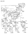
液圧ブレーキシステムは、図16に示すブレーキ回路を含むものとすることができる。その他の部分については実施例1における場合と同様である。図16に示す液圧ブレーキ回路において、マスタシリンダ62の加圧室72には、メカ弁入力通路310を介してメカ式増圧装置96に接続される。また、メカ式増圧装置96には、バイパス通路136が設けられるため、加圧室72は、メカ弁入力通路310,バイパス通路136,サーボ圧通路190,共通通路94,個別通路150FL,150FRを介してブレーキシリンダ42FL,FRに接続されることになる。そのため、これらメカ弁入力通路310,バイパス通路136,サーボ圧通路190,共通通路94,個別通路150FL,FR等によりマスタ通路(メカ式増圧装置96をバイパスしない通路であり、非直結型マニュアル通路311と称することができる)が構成されると考えることができる。   The hydraulic brake system may include a brake circuit shown in FIG. Other portions are the same as those in the first embodiment. In the hydraulic brake circuit shown in FIG. 16, the pressurizing chamber 72 of the master cylinder 62 is connected to a mechanical pressure booster 96 via a mechanical valve input passage 310. Further, since the mechanical pressure intensifier 96 is provided with a bypass passage 136, the pressurizing chamber 72 has a mechanical valve input passage 310, a bypass passage 136, a servo pressure passage 190, a common passage 94, and individual passages 150FL and 150FR. To the brake cylinders 42FL and FR. Therefore, the mechanical valve input passage 310, the bypass passage 136, the servo pressure passage 190, the common passage 94, the individual passage 150FL, FR, etc. are used as master passages (passages that do not bypass the mechanical pressure booster 96 and are not directly connected manual passages). 311) can be considered.

また、メカ式増圧装置96と動力式液圧源64との間の高圧通路132には、高圧側逆止弁100と直列に、高圧遮断弁312が設けられる。本実施例において、高圧遮断弁312が高圧側逆止弁100より動力式液圧源64側に設けられるが、配置は問わない。高圧遮断弁312の開状態においては、高圧側逆止弁100の機能が発揮される。メカ式増圧装置96から動力式液圧源64へ向かう作動液の流れが阻止され、動力式液圧源64の液圧がメカ式増圧装置96の液圧より大きい場合に、動力式液圧源64からメカ式増圧装置96への作動液の流れが許容される。しかし、高圧遮断弁312の閉状態においては、高圧側逆止弁100の機能が発揮されない。高圧室114における作動液の流入・流出が阻止され、メカ式増圧装置96の作動が阻止される。   Further, a high-pressure shut-off valve 312 is provided in series with the high-pressure check valve 100 in the high-pressure passage 132 between the mechanical pressure booster 96 and the power-type hydraulic pressure source 64. In this embodiment, the high-pressure shut-off valve 312 is provided on the power hydraulic pressure source 64 side from the high-pressure check valve 100, but the arrangement is not limited. In the open state of the high pressure shut-off valve 312, the function of the high pressure check valve 100 is exhibited. When the flow of hydraulic fluid from the mechanical pressure booster 96 to the power hydraulic pressure source 64 is blocked and the hydraulic pressure of the power hydraulic pressure source 64 is larger than the hydraulic pressure of the mechanical pressure booster 96, the power hydraulic fluid The flow of hydraulic fluid from the pressure source 64 to the mechanical pressure booster 96 is allowed. However, in the closed state of the high pressure shut-off valve 312, the function of the high pressure side check valve 100 is not exhibited. The inflow / outflow of the hydraulic fluid in the high pressure chamber 114 is blocked, and the operation of the mechanical pressure intensifier 96 is blocked.

さらに、メカ弁入力通路310の途中には、実施例1における場合と同様に、入力側遮断弁148が設けられるが、入力側遮断弁148は、閉状態において、ブレーキシリンダへのマスタシリンダ62の作動液の流入を阻止するため、マスタ遮断弁に対応すると考えることができる。入力側遮断弁148は非直結型マニュアル通路に設けられるのであり、常開弁である。また、本実施例においては、減圧リニア制御弁316が共通通路94とリザーバ78との間に設けられる。減圧リニア制御弁316は図3に示す増圧リニア制御弁172と構造はほぼ同じものであり、共通通路94の液圧とリザーバ78の液圧との差圧に応じた差圧作用力が弁子180を弁座182から離間させる方向に作用する。そして、ソレノイド186への供給電流の連続的な制御により、共通通路94の液圧の大きさが制御される。なお、減圧リニア制御弁316は不可欠ではなく、実施例1における場合と同様に、保持弁153の開状態において、減圧弁156を用いて共通通路94の液圧を減圧制御することもできる。   Further, an input side shut-off valve 148 is provided in the middle of the mechanical valve input passage 310 as in the first embodiment. The input side shut-off valve 148 is closed when the master cylinder 62 is connected to the brake cylinder. In order to prevent the inflow of hydraulic fluid, it can be considered to correspond to a master cutoff valve. The input side shut-off valve 148 is provided in the non-directly connected manual passage and is a normally open valve. In this embodiment, the pressure-reducing linear control valve 316 is provided between the common passage 94 and the reservoir 78. The pressure-reducing linear control valve 316 has substantially the same structure as the pressure-increasing linear control valve 172 shown in FIG. 3, and a differential pressure acting force corresponding to the pressure difference between the fluid pressure in the common passage 94 and the fluid pressure in the reservoir 78 is the valve. This acts in the direction of separating the child 180 from the valve seat 182. The magnitude of the hydraulic pressure in the common passage 94 is controlled by continuous control of the current supplied to the solenoid 186. Note that the pressure-reducing linear control valve 316 is not indispensable, and the hydraulic pressure in the common passage 94 can be controlled to be reduced by using the pressure-reducing valve 156 when the holding valve 153 is open as in the first embodiment.

さらに、共通通路94の、サーボ圧通路190の接続部と個別通路150RRの接続部との間には分離弁320が設けられる。分離弁320は、常閉の電磁開閉弁である。換言すれば、メカ式増圧装置96は、共通通路94の分離弁320が設けられた部分より前輪2,4のブレーキシリンダ42FL,FRが接続される側の部分に接続される。また、左右後輪46,48のブレーキシリンダ52RL,RRに対応して設けられた保持弁153RLa,RRaは、常開弁とされる。   Further, a separation valve 320 is provided between the common passage 94 and the connection portion of the servo pressure passage 190 and the connection portion of the individual passage 150RR. The separation valve 320 is a normally closed electromagnetic on-off valve. In other words, the mechanical pressure booster 96 is connected to a portion of the common passage 94 on the side where the brake cylinders 42FL and FR of the front wheels 2 and 4 are connected to a portion where the separation valve 320 is provided. The holding valves 153RLa and RRa provided corresponding to the brake cylinders 52RL and RR of the left and right rear wheels 46 and 48 are normally opened.

なお、分離弁320は不可欠ではない。また、保持弁153RLa,RRaは常閉弁とすることもできる。   Note that the separation valve 320 is not essential. Further, the holding valves 153RLa and RRa can be normally closed valves.

一方、本実施例において、出力側遮断弁192は設けられない。高圧遮断弁312の閉状態においてメカ式可動部98が作動し難くされる。また、入力側遮断弁148の閉状態においてマスタシリンダ62の液圧が大径側室110に供給されることがないのであり、マスタシリンダ62の液圧により段付きピストン104が前進させられることはない。そのため、高圧遮断弁312が閉状態とされ、かつ、入力側遮断弁148が閉状態とされることにより、出力側遮断弁を閉状態にした場合とほぼ同様の効果が得られる。そのため、出力側遮断弁をメカ式増圧装置96の出力側に設ける必要性は低いのである。また、加圧室72にマスタ通路74(直結型マスタ通路)が接続されていなし。マスタ通路311(非直結型マスタ通路)が設けられているため、並行して、マスタ通路74を設ける必要性は低いのである。さらに、マスタ通路76に、マスタシリンダ圧センサ222FRが設けられる。マスタシリンダ圧センサが2つ設けられることにより、一方が異常になっても他方によりマスタシリンダ圧を検出することができる。   On the other hand, in this embodiment, the output side shut-off valve 192 is not provided. When the high-pressure shut-off valve 312 is in the closed state, the mechanical movable portion 98 is hardly operated. Further, the hydraulic pressure of the master cylinder 62 is not supplied to the large-diameter side chamber 110 when the input-side shut-off valve 148 is closed, and the stepped piston 104 is not moved forward by the hydraulic pressure of the master cylinder 62. . Therefore, when the high-pressure shut-off valve 312 is closed and the input-side shut-off valve 148 is closed, substantially the same effect as when the output-side shut-off valve is closed is obtained. Therefore, it is not necessary to provide the output side shut-off valve on the output side of the mechanical pressure booster 96. Further, the master passage 74 (directly connected master passage) is not connected to the pressurizing chamber 72. Since the master passage 311 (non-directly connected master passage) is provided, the necessity of providing the master passage 74 in parallel is low. Further, a master cylinder pressure sensor 222FR is provided in the master passage 76. By providing two master cylinder pressure sensors, the master cylinder pressure can be detected by the other even if one becomes abnormal.

<液圧ブレーキ装置における作動>
1)システムが正常である場合
図17に示すように入力側遮断弁148が閉状態とされ、シミュレータ制御弁202が開状態とされ、高圧遮断弁312が閉状態とされる。また、左右後輪46,48の減圧弁156RL,RRが閉状態とされ、分離弁320が開状態とされる。ブレーキシリンダ42FRがマスタシリンダ62から遮断され、メカ式増圧装置96の作動が禁止された状態で、動力式液圧源64の出力液圧を利用して、共通通路94の液圧が、増圧リニア制御弁172,減圧リニア制御弁316により制御され、ブレーキシリンダ42,52に供給される。共通通路94とメカ式増圧装置96の小径側室112とは連通状態にあるが、入力側遮断弁148が閉状態にあるため、小径側室112の液圧がマスタ入力通路310に戻されることはない。また、高圧遮断弁312が閉状態にあるため、アキュムレータ66の液圧が高圧室114に供給されることはないのであり、小径側室112の液圧は保持される。後述するように、小径側室112の液圧がピストン内逆止弁130を経て大径側室110に供給されることにより、段付きピストン104が前進させられ、開弁部材125に当接して、ピストン内連通路129が塞がれる。また、入力側遮断弁148が閉状態にあるため、原則として、段付きピストン104の後退は阻止される。そのため、このことが、共通通路94の液圧の制御に影響を与えることは殆どないと考えられる。
本実施例においては、保持弁153RLa,RRaが常開弁とされるため、通常のブレーキ作動時にソレノイドに電流を供給する必要がなくなり、その分、消費電力の低減を図ることができる。
<Operation in hydraulic brake device>
1) When the system is normal As shown in FIG. 17, the input side shutoff valve 148 is closed, the simulator control valve 202 is opened, and the high pressure shutoff valve 312 is closed. Further, the pressure reducing valves 156RL, RR of the left and right rear wheels 46, 48 are closed, and the separation valve 320 is opened. In the state where the brake cylinder 42FR is disconnected from the master cylinder 62 and the operation of the mechanical pressure increasing device 96 is prohibited, the hydraulic pressure in the common passage 94 is increased by using the output hydraulic pressure of the power hydraulic pressure source 64. It is controlled by the pressure linear control valve 172 and the pressure reduction linear control valve 316 and supplied to the brake cylinders 42 and 52. Although the common passage 94 and the small-diameter side chamber 112 of the mechanical pressure increasing device 96 are in communication with each other, the hydraulic pressure in the small-diameter side chamber 112 is returned to the master input passage 310 because the input-side shut-off valve 148 is closed. Absent. Further, since the high pressure shut-off valve 312 is in the closed state, the hydraulic pressure of the accumulator 66 is not supplied to the high pressure chamber 114, and the hydraulic pressure of the small diameter side chamber 112 is maintained. As will be described later, when the hydraulic pressure in the small-diameter side chamber 112 is supplied to the large-diameter side chamber 110 via the in-piston check valve 130, the stepped piston 104 is advanced and comes into contact with the valve-opening member 125. The inner communication path 129 is blocked. Further, since the input side shut-off valve 148 is in the closed state, the stepped piston 104 is prevented from retreating in principle. For this reason, it is considered that this hardly affects the control of the hydraulic pressure in the common passage 94.
In the present embodiment, since the holding valves 153RLa and RRa are normally opened, it is not necessary to supply current to the solenoid during normal braking operation, and power consumption can be reduced accordingly.

2)制御系が異常である場合
図18、19に示すように、すべてのソレノイドに電流が供給されなくなることにより原位置に戻される。
2−1)大径側室110の液圧がメカ式可動部98の作動開始圧以下の場合
図18に示すように、大径側室110の液圧がメカ式可動部98の作動開始圧以下の場合には、加圧室72の液圧は、メカ弁入力通路310,バイパス通路136、サーボ圧通路190を経て共通通路94に供給され、左右前輪2,4のブレーキシリンダ42に供給される。入力側逆止弁99の開弁圧は非常に小さいため、ブレーキペダル60の操作に伴って速やかにブレーキシリンダ42に作動液を供給することが可能となり、液圧ブレーキ40の効き遅れを小さくすることができる。このように、制御系の異常時に、左右前輪2,4のブレーキシリンダ42FL,FRが作動させられるため、車両の重心が左右方向のほぼ中心にある場合に、ヨーモーメントが生じ難くすることができる。
2) When the control system is abnormal As shown in FIGS. 18 and 19, the current is not supplied to all the solenoids, so that the control system is returned to the original position.
2-1) When the hydraulic pressure in the large-diameter side chamber 110 is equal to or lower than the operation start pressure of the mechanical movable unit 98 As shown in FIG. In this case, the hydraulic pressure in the pressurizing chamber 72 is supplied to the common passage 94 through the mechanical valve input passage 310, the bypass passage 136, and the servo pressure passage 190, and is supplied to the brake cylinders 42 of the left and right front wheels 2 and 4. Since the valve opening pressure of the input-side check valve 99 is very small, it becomes possible to quickly supply the hydraulic fluid to the brake cylinder 42 in accordance with the operation of the brake pedal 60, and to reduce the delay in the effect of the hydraulic brake 40. be able to. As described above, when the control system is abnormal, the brake cylinders 42FL and FR of the left and right front wheels 2 and 4 are actuated, so that the yaw moment can be hardly generated when the center of gravity of the vehicle is substantially at the center in the left and right direction. .

2−2)加圧室72の液圧がメカ式可動部98の作動開始圧より大きい場合
2−2−1)アキュムレータ66に蓄えられた作動液の液圧が作動許可圧より大きい場合
ポンプ装置65の作動が停止させられても、アキュムレータ66に蓄えられた作動液の液圧が作動許可圧より大きい場合には、メカ式可動部98の作動が許可される。図19の実線が示すように、大径側室110の液圧によって段付きピストン104が前進させられ、開弁部材125に当接し、高圧供給弁116が開状態に切り換えられる。小径側室112が大径側室110から遮断され、アキュムレータ66から高圧側逆止弁100を経て高圧室114に高圧の作動液が供給される。小径側室112の液圧(サーボ圧)は、マスタシリンダ62の液圧より高くされ、共通通路94に供給され、左右前輪2,4のブレーキシリンダ42FL,42RRに供給される。小径側室112の液圧は、大径側室110の液圧と、段付きピストン104の大径部と小径部との受圧面積の比率とで決まる大きさとされる。
2-2) When the hydraulic pressure in the pressurizing chamber 72 is higher than the operation start pressure of the mechanical movable unit 98 2-2-1) When the hydraulic pressure of the hydraulic fluid stored in the accumulator 66 is higher than the operation permission pressure Even if the operation of 65 is stopped, if the hydraulic pressure of the hydraulic fluid stored in the accumulator 66 is higher than the operation permission pressure, the operation of the mechanical movable unit 98 is permitted. As indicated by the solid line in FIG. 19, the stepped piston 104 is advanced by the hydraulic pressure in the large-diameter side chamber 110, contacts the valve opening member 125, and the high-pressure supply valve 116 is switched to the open state. The small-diameter side chamber 112 is shut off from the large-diameter side chamber 110, and high-pressure hydraulic fluid is supplied from the accumulator 66 through the high-pressure side check valve 100 to the high-pressure chamber 114. The hydraulic pressure (servo pressure) in the small-diameter side chamber 112 is made higher than the hydraulic pressure in the master cylinder 62, supplied to the common passage 94, and supplied to the brake cylinders 42 FL and 42 RR of the left and right front wheels 2 and 4. The hydraulic pressure in the small diameter side chamber 112 is determined by the hydraulic pressure in the large diameter side chamber 110 and the ratio of the pressure receiving area between the large diameter portion and the small diameter portion of the stepped piston 104.

2−2−2)アキュムレータ66に蓄えられた作動液の液圧が作動許可圧以下である場合
アキュムレータ66に蓄えられた作動液の液圧が設定圧以下である場合には、図18に示す場合と同様に、マスタシリンダ62の加圧室72の液圧は、メカ弁入力通路310,バイパス通路136,サーボ圧通路190,共通通路94を経て左右前輪2,4のブレーキシリンダ42に供給される。一方、液圧ブレーキ40の作動当初は、アキュムレータ66に蓄えられた作動液の液圧が作動許可圧より高い状態にあったが、メカ式可動部98の作動によりアキュムレータ66に蓄えられた作動液の液圧が低下して作動許可圧より低くなると、アキュムレータ66から高圧室114に作動液が供給されなくなる。それにより、メカ式可動部98の作動が不能となる。例えば、ポンピングブレーキ操作が行われた場合には、アキュムレータ66の作動液の消費量が多くなり、アキュムレータ圧が低くなることがある。段付きピストン104の前進が阻止され(ストッパに当接すると考えられる)、小径側室112の液圧はそれ以上高くなることがないのであり、メカ式可動部98は倍力機能を発揮できなくなる。小径側室112の液圧より加圧室72の液圧の方が高くなり、図19の破線が示すように、マスタシリンダ62の加圧室72の液圧が、バイパス通路136,サーボ圧通路190を経て共通通路94に供給される。マスタシリンダ62の加圧室72の液圧は、倍力されることなく、左右前輪2,4のブレーキシリンダ42FL,42FRに供給される。
2-2-2) When the hydraulic pressure of the hydraulic fluid stored in the accumulator 66 is equal to or lower than the operation permission pressure When the hydraulic pressure of the hydraulic fluid stored in the accumulator 66 is equal to or lower than the set pressure, it is shown in FIG. Similarly to the case, the hydraulic pressure in the pressurizing chamber 72 of the master cylinder 62 is supplied to the brake cylinders 42 of the left and right front wheels 2, 4 through the mechanical valve input passage 310, the bypass passage 136, the servo pressure passage 190, and the common passage 94. The On the other hand, at the beginning of the operation of the hydraulic brake 40, the hydraulic pressure of the hydraulic fluid stored in the accumulator 66 was higher than the operation permission pressure. However, the hydraulic fluid stored in the accumulator 66 by the operation of the mechanical movable unit 98. When the hydraulic pressure of the accumulator 66 decreases and becomes lower than the operation permission pressure, the hydraulic fluid is not supplied from the accumulator 66 to the high pressure chamber 114. Thereby, the operation of the mechanical movable unit 98 becomes impossible. For example, when a pumping brake operation is performed, the amount of hydraulic fluid consumed by the accumulator 66 increases and the accumulator pressure may decrease. The forward movement of the stepped piston 104 is prevented (it is considered to abut against the stopper), and the hydraulic pressure in the small-diameter side chamber 112 does not increase any more, and the mechanical movable unit 98 cannot exhibit the boosting function. The hydraulic pressure in the pressurizing chamber 72 is higher than the hydraulic pressure in the small-diameter side chamber 112, and as shown by the broken line in FIG. 19, the hydraulic pressure in the pressurizing chamber 72 of the master cylinder 62 is changed to the bypass passage 136 and the servo pressure passage 190. And supplied to the common passage 94. The hydraulic pressure in the pressurizing chamber 72 of the master cylinder 62 is supplied to the brake cylinders 42FL and 42FR of the left and right front wheels 2 and 4 without being boosted.

また、分離弁320が閉状態にあるため、左右後輪46,48のブレーキシリンダ52RL、52RRに、メカ式可動部98の液圧が供給されないようにされている。その結果、液不足が抑制され、左右前輪2,4のブレーキシリンダ42FL、FRの増圧不足を抑制することができる。さらに、マスタシリンダ62において加圧室72の容積を大きくすることができる。加圧室72の容積を大きくすれば、左右前輪2,4のブレーキシリンダ42FL,FRの両方に作動液が供給される場合であっても、液量不足が生じることを回避することができる。この場合には、運転者のブレーキペダル60のストロークが大きくなることもある。   Further, since the separation valve 320 is in the closed state, the hydraulic pressure of the mechanical movable portion 98 is prevented from being supplied to the brake cylinders 52RL and 52RR of the left and right rear wheels 46 and 48. As a result, liquid shortage is suppressed, and insufficient pressure increase of the brake cylinders 42FL and FR of the left and right front wheels 2 and 4 can be suppressed. Furthermore, the volume of the pressurizing chamber 72 in the master cylinder 62 can be increased. If the volume of the pressurizing chamber 72 is increased, it is possible to avoid a shortage of fluid even when hydraulic fluid is supplied to both the brake cylinders 42FL and FR of the left and right front wheels 2 and 4. In this case, the stroke of the driver's brake pedal 60 may be increased.

3)漏れの可能性がある場合
図20に示すように、入力側遮断弁148が開状態とされ、高圧遮断弁312が閉状態とされ、マスタ遮断弁194FRが開状態とされる。また、左右後輪46,48について減圧弁156RL,RRが閉状態とされる。また、分離弁320が閉状態とされ、右前輪4の保持弁153FRが閉状態とされる。
(a)左右後輪46,48のブレーキシリンダ52は、左右前輪2,4のブレーキシリンダ42から遮断された状態で、動力式液圧源64の液圧が増圧リニア制御弁172,減圧リニア制御弁316によって制御されて、供給される。
(b)右前輪4のブレーキシリンダ42FRには、3輪のブレーキシリンダ42FL、52RL、RRから遮断された状態で、マスタシリンダ62の加圧室70の液圧が供給される。
(c)左前輪2のブレーキシリンダ42FLには、左右後輪46,48のブレーキシリンダ52RL,RR、右前輪4のブレーキシリンダ42FRから遮断された状態で、加圧室72の液圧が、メカ式増圧装置96(バイパス通路136)を通って供給される。
この場合において、高圧遮断弁312が閉状態にあるため、入力側遮断弁148が開状態にあってもメカ式可動部98の作動が阻止される。そのため、左右前輪2,4のブレーキシリンダ42FL,FRには、等しい液圧が供給される。
3) When there is a possibility of leakage As shown in FIG. 20, the input side shutoff valve 148 is opened, the high pressure shutoff valve 312 is closed, and the master shutoff valve 194FR is opened. Further, the pressure reducing valves 156RL, RR are closed for the left and right rear wheels 46, 48. Further, the separation valve 320 is closed, and the holding valve 153FR of the right front wheel 4 is closed.
(a) While the brake cylinders 52 of the left and right rear wheels 46 and 48 are disconnected from the brake cylinders 42 of the left and right front wheels 2 and 4, the hydraulic pressure of the power hydraulic pressure source 64 is increased by the linear pressure increasing control valve 172 Controlled by a control valve 316 and supplied.
(b) The hydraulic pressure in the pressurizing chamber 70 of the master cylinder 62 is supplied to the brake cylinder 42FR of the right front wheel 4 while being disconnected from the three brake cylinders 42FL, 52RL, RR.
(c) The hydraulic pressure in the pressurizing chamber 72 is mechanically applied to the brake cylinder 42FL of the left front wheel 2 while being disconnected from the brake cylinders 52RL and RR of the left and right rear wheels 46 and 48 and the brake cylinder 42FR of the right front wheel 4. Supplied through a pressure booster 96 (bypass passage 136).
In this case, since the high-pressure shut-off valve 312 is in the closed state, the operation of the mechanical movable unit 98 is prevented even when the input-side shut-off valve 148 is in the open state. Therefore, equal hydraulic pressure is supplied to the brake cylinders 42FL, FR of the left and right front wheels 2, 4.

また、高圧遮断弁312が閉状態とされることにより、動力式液圧源64の液圧がメカ式増圧装置96に供給されることが阻止され、3つのブレーキ系統330FL,FR,Rを互いに独立にすることができる。仮に、高圧遮断弁312が開状態にある場合(高圧遮断弁312が設けられていない場合)には、動力式液圧源64の液圧が、左右後輪46,48のブレーキシリンダ52を含むブレーキ系統330Rにも、左前輪2のブレーキシリンダ42FLを含むブレーキ系統330FLにも供給され、これらブレーキ系統330R、330FLを独立にすることができない。そのため、仮に、ブレーキ系統330FLにおいて液漏れが生じたとした場合には、動力式液圧源64の液圧がブレーキ系統330FLにおいて消費され、ブレーキ系統330Rにも影響が及ぶ場合がある。それに対して、高圧遮断弁312が閉状態とされれば、仮に、ブレーキ系統330FLにおいて液漏れが生じた場合であっても、動力式液圧源64からメカ式増圧装置96を経て流出させられることを阻止することができる。   Further, by closing the high-pressure shut-off valve 312, the hydraulic pressure of the power hydraulic pressure source 64 is prevented from being supplied to the mechanical pressure booster 96, and the three brake systems 330 FL, FR, and R are connected. Can be independent of each other. If the high-pressure shut-off valve 312 is in an open state (when the high-pressure shut-off valve 312 is not provided), the hydraulic pressure of the power-type hydraulic pressure source 64 includes the brake cylinders 52 of the left and right rear wheels 46 and 48. The brake system 330R is also supplied to the brake system 330FL including the brake cylinder 42FL of the left front wheel 2, and the brake systems 330R and 330FL cannot be made independent. For this reason, if a fluid leak occurs in the brake system 330FL, the hydraulic pressure of the power hydraulic pressure source 64 is consumed in the brake system 330FL, which may affect the brake system 330R. On the other hand, if the high-pressure shut-off valve 312 is closed, even if a liquid leak occurs in the brake system 330FL, the high-pressure shut-off valve 312 is caused to flow out from the power hydraulic pressure source 64 via the mechanical pressure booster 96. Can be prevented.

すなわち、高圧遮断弁312が閉状態とされ、かつ、分離弁320が閉状態とされることにより、それぞれ、3つのブレーキ系統330FL,FR,Rを互いに独立とすることができる。そのため、これら3つのブレーキ系統のうちの1つにおいて液漏れが生じても、それの影響が他のブレーキ系統に及ばないようにすることができる。ブレーキ系統330FRは、ブレーキシリンダ42FR、マスタ通路76,加圧室70,収容室80等を含むものであり、ブレーキ系統330FLは、ブレーキシリンダ42FL、個別通路150FL,共通通路94,サーボ圧通路190,メカ式増圧装置96,マスタ入力通路310,加圧室72,収容室82等を含むものであり、ブレーキ系統330Rは、ブレーキシリンダ52RL,RR,個別通路150RL、RR,動力式液圧源64,収容室84等を含むものである。したがって、ブレーキ系統330FR,FL,Rが互いに独立にされるということは、マスタリザーバ78の収容室80,82,84も互いに独立にされるということである。   That is, when the high-pressure cutoff valve 312 is closed and the separation valve 320 is closed, the three brake systems 330FL, FR, and R can be made independent of each other. Therefore, even if liquid leakage occurs in one of these three brake systems, it is possible to prevent the influence from affecting other brake systems. The brake system 330FR includes a brake cylinder 42FR, a master passage 76, a pressurizing chamber 70, a storage chamber 80, and the like. The brake system 330FL includes a brake cylinder 42FL, an individual passage 150FL, a common passage 94, a servo pressure passage 190, A mechanical pressure intensifying device 96, a master input passage 310, a pressurizing chamber 72, a storage chamber 82, and the like are included. A brake system 330R includes brake cylinders 52RL and RR, individual passages 150RL and RR, and a power hydraulic pressure source 64. , Including the storage chamber 84 and the like. Therefore, the fact that the brake systems 330FR, FL, R are made independent from each other means that the storage chambers 80, 82, 84 of the master reservoir 78 are also made independent from each other.

また、制御系が異常(例えば、ポンプ装置65の作動が不能であるが、電磁開閉弁の制御が可能)であり、かつ、アキュムレータ66に蓄えられた液圧が作動許可圧より低い場合には、図18の状態に切り換えるより、図20の状態に切り換えた方が有効な場合がある。メカ式可動部98の作動が禁止された状態においては、図18の状態において、左右前輪のブレーキシリンダ42FL,FRに、加圧室72の液圧が供給されるのに対して、図20の状態においては、左右前輪2,4のブレーキシリンダ42FL,FRに、それぞれ、加圧室72,70が連通させられる。それにより、ブレーキシリンダ42FL,FRの各々における作動液不足が生じ難くすることができる。   Further, when the control system is abnormal (for example, the pump device 65 cannot be operated but the electromagnetic on-off valve can be controlled) and the hydraulic pressure stored in the accumulator 66 is lower than the operation permission pressure. In some cases, switching to the state of FIG. 20 is more effective than switching to the state of FIG. In the state where the operation of the mechanical movable portion 98 is prohibited, in the state of FIG. 18, the hydraulic pressure in the pressurizing chamber 72 is supplied to the brake cylinders 42FL and FR of the left and right front wheels, whereas in FIG. In the state, the pressurizing chambers 72 and 70 are communicated with the brake cylinders 42FL and FR of the left and right front wheels 2 and 4, respectively. As a result, the hydraulic fluid shortage in each of the brake cylinders 42FL and FR can be made difficult to occur.

4)液圧ブレーキが解除される場合
ブレーキ操作が解除されると、すべてのバルブのソレノイドに電流が供給されなくなることにより、図16の原位置に戻される。また、メカ式増圧装置96において、段付きピストン104が開弁部材125から離間させられる。左右前輪2,4のブレーキシリンダ42FL,FRの液圧はピストン内連通路129,ピストン内逆止弁130を経てマスタシリンダ62(マスタリザーバ78)に戻される。また、左右後輪46,48のブレーキシリンダ52RL,RRの液圧は、減圧弁156を経てリザーバ78に戻される。
4) When the hydraulic brake is released When the brake operation is released, the current is not supplied to the solenoids of all the valves, thereby returning the original position of FIG. Further, in the mechanical pressure increasing device 96, the stepped piston 104 is separated from the valve opening member 125. The hydraulic pressures in the brake cylinders 42FL and FR of the left and right front wheels 2 and 4 are returned to the master cylinder 62 (master reservoir 78) through the in-piston communication passage 129 and the in-piston check valve 130. The hydraulic pressures in the brake cylinders 52RL and RR of the left and right rear wheels 46 and 48 are returned to the reservoir 78 via the pressure reducing valve 156.

5)イグニッションスイッチ234のOFF状態
すべての電磁開閉弁のソレノイドに電流が供給されなくなることにより、図16に示す原位置に戻される。実施例1における場合と同様に、3つのブレーキ系統330FR,FL,Rが独立にされるため、1つの系統で液漏れが生じても、他の系統に、その影響が及ぶことが良好に回避される。また、メカ式増圧装置96には流出防止装置が設けられるため、メカ式増圧装置96を通るマスタリザーバ78からの作動液の流出を阻止ることができる。
5) Ignition switch 234 OFF state When no current is supplied to the solenoids of all the solenoid on / off valves, the ignition switch 234 is returned to the original position shown in FIG. As in the case of the first embodiment, since the three brake systems 330FR, FL, and R are made independent, even if liquid leakage occurs in one system, it is well avoided that the influence is exerted on other systems. Is done. Further, since the mechanical pressure booster 96 is provided with an outflow prevention device, it is possible to prevent the hydraulic fluid from flowing out of the master reservoir 78 that passes through the mechanical pressure booster 96.

6)メカ式増圧装置96のチェック
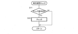
本実施例においては、予め定められたチェック条件が成立すると、メカ式増圧装置96の作動が正常であるか否かのチェックが行われる。
図21のフローチャートで表されるチェックプログラムは予め定められた設定時間毎に実行される。S11において、チェック条件が成立するか否かが判定される。チェック条件が成立しない場合には、チェックが行われることはないが、チェック条件が成立すると、S12においてメカ式増圧装置96の作動チェックが行われる。本実施例においては、(i)イグニッションスイッチ234がOFFからONに切り換えられた後の最初にブレーキペダル60が作用操作された場合、(ii)車両が停止状態にある場合に成立したとされる。車輪速度センサ230の検出値に基づいて取得された車両の走行速度が停止状態にあるとみなし得る設定速度以下である場合に、車両が停止状態にあると考えることができる。
6) Check of mechanical pressure booster 96 In this embodiment, when a predetermined check condition is satisfied, it is checked whether or not the operation of the mechanical pressure booster 96 is normal.
The check program represented by the flowchart of FIG. 21 is executed at predetermined time intervals. In S11, it is determined whether or not a check condition is satisfied. If the check condition is not satisfied, no check is performed, but if the check condition is satisfied, an operation check of the mechanical pressure booster 96 is performed in S12. In this embodiment, (i) when the brake pedal 60 is operated for the first time after the ignition switch 234 is switched from OFF to ON, (ii) when the vehicle is stopped. . It can be considered that the vehicle is in a stopped state when the traveling speed of the vehicle acquired based on the detection value of the wheel speed sensor 230 is equal to or lower than a set speed that can be considered to be in the stopped state.

このように、チェックは、ブレーキペダル60の作用操作状態で行われる。また、チェックは車両の停止状態において行われることが望ましいが、停止状態に行うことは不可欠ではない。さらに、チェックにはチェック1,チェック2の2つの方法がある。チェック1,2は、適宜、選択的に行われるようにしても、チェック条件が成立した場合に、チェック1,2の両方が行われるようにしても、マスタシリンダ液圧が設定圧以上の場合にチェック1が行われ、設定圧より低い場合にチェック2が行われるようにすることができる。後述するように、マスタシリンダ液圧の設定圧は、チェック1によってメカ式増圧装置96の作動が正常であるか否かの判定を正確に行い得る大きさとすることができる。設定圧はチェック可能圧と称することができる。   As described above, the check is performed in the operation operation state of the brake pedal 60. Further, it is desirable that the check be performed while the vehicle is stopped, but it is not essential to perform the check while the vehicle is stopped. Furthermore, there are two methods of check, check 1 and check 2. Checks 1 and 2 may be performed selectively as appropriate, or when the check condition is satisfied, both checks 1 and 2 may be performed, or the master cylinder hydraulic pressure is greater than or equal to the set pressure Check 1 can be performed, and when the pressure is lower than the set pressure, Check 2 can be performed. As will be described later, the set pressure of the master cylinder hydraulic pressure can be set to such a level that the check 1 can accurately determine whether or not the operation of the mechanical pressure booster 96 is normal. The set pressure can be referred to as a checkable pressure.

6−1)チェック1
チェック1においては、メカ弁可動部98の入力液圧Pin(Pm)とメカ弁可動部98の出力液圧Pout(Pwc)とを比較して、メカ式増圧装置96の作動が正常であるか否かが検出される。図22(a)に示すように、増圧リニア制御弁172,減圧リニア制御弁316を閉状態として、入力側遮断弁148を開状態、高圧遮断弁314を開状態として、メカ式増圧装置96の作動を許可する。そして、マスタシリンダ圧センサ222FLの検出値Pm(メカ弁可動部98の入力液圧Pin)と、ブレーキシリンダ圧センサ226の検出値Pw(メカ弁可動部98の出力液圧Pout)とを比較する。これらが、図22(b)に示す正常領域R内に属する場合に、メカ式増圧装置96の作動は正常であると判定することができる。それに対して、正常領域R内にない場合には、メカ式増圧装置96の作動が異常であると判定される。図22(b)の実線は、メカ式増圧装置96の作動が正常である場合のPinとPoutとの関係を示す。
6-1) Check 1
In Check 1, the operation of the mechanical pressure intensifier 96 is normal by comparing the input hydraulic pressure Pin (Pm) of the mechanical valve movable portion 98 with the output hydraulic pressure Pout (Pwc) of the mechanical valve movable portion 98. Is detected. As shown in FIG. 22 (a), the pressure-increasing linear control valve 172 and the pressure-decreasing linear control valve 316 are closed, the input side shut-off valve 148 is opened, and the high-pressure shut-off valve 314 is opened. 96 operations are allowed. Then, the detection value Pm of the master cylinder pressure sensor 222FL (the input hydraulic pressure Pin of the mechanical valve movable unit 98) and the detection value Pw of the brake cylinder pressure sensor 226 (the output hydraulic pressure Pout of the mechanical valve movable unit 98) are compared. . When these belong to the normal region R shown in FIG. 22B, it can be determined that the operation of the mechanical pressure intensifying device 96 is normal. On the other hand, when not in the normal region R, it is determined that the operation of the mechanical pressure booster 96 is abnormal. The solid line in FIG. 22 (b) shows the relationship between Pin and Pout when the mechanical pressure booster 96 is operating normally.

メカ式増圧装置96の作動が異常であるのは、(a)動力式液圧源64の異常(動力式液圧源64の出力液圧が低い場合、動力式液圧源64から高圧の液圧が供給されない場合であり、例えば、アキュムレータ66の液漏れ、ポンプモータ92の故障、高圧通路132の液漏れ等の原因が考えられる)、(b)高圧遮断弁312の閉固着異常、(c)メカ式増圧装置96の異常(メカ式可動部98が作動しない場合であり、例えば、段付きピストン104の食い付き等の作動不能異常、高圧供給弁116の閉固着異常等の原因が考えられる)、(d)入力側遮断弁148の開固着異常等のうちの少なくとも1つが原因であると考えられる。また、マスタシリンダ圧センサ222FL、ブレーキシリンダ圧センサ226の異常、分離弁320の閉固着異常、液漏れ等も考えられる。それに対して、メカ式増圧装置96の作動が正常である場合には、メカ式可動部98の作動が正常であり、かつ、動力式液圧源64から高圧の作動液が供給され、高圧遮断弁312,入力側遮断弁148が指令通りに開状態に切り換わったと考えられる。換言すれば、メカ式増圧装置96の作動が正常である場合には、メカ式増圧装置96が正常である場合のみならず、メカ式増圧装置96の作動に関連する部材、装置等も正常であると判定することができる。   The operation of the mechanical pressure increasing device 96 is abnormal because (a) the power hydraulic pressure source 64 is abnormal (if the output hydraulic pressure of the power hydraulic pressure source 64 is low, the power hydraulic pressure source 64 This is a case where the hydraulic pressure is not supplied. For example, there may be causes such as liquid leakage of the accumulator 66, failure of the pump motor 92, liquid leakage of the high-pressure passage 132, etc.), (b) abnormal closure of the high-pressure cutoff valve 312; c) Abnormality of the mechanical pressure booster 96 (this is a case where the mechanical movable part 98 does not operate. For example, there are causes such as an inoperable abnormality such as a biting of the stepped piston 104, an abnormal close fixation of the high pressure supply valve 116, etc. (D) It is considered that this is caused by at least one of (d) an abnormally open sticking abnormality of the input side shut-off valve 148 and the like. Also, abnormalities in the master cylinder pressure sensor 222FL and the brake cylinder pressure sensor 226, abnormal closure of the separation valve 320, liquid leakage, etc. can be considered. On the other hand, when the operation of the mechanical pressure intensifying device 96 is normal, the operation of the mechanical movable unit 98 is normal, and the high-pressure hydraulic fluid is supplied from the power hydraulic pressure source 64, and the high pressure It is considered that the shut-off valve 312 and the input-side shut-off valve 148 are switched to the open state as instructed. In other words, when the operation of the mechanical pressure increase device 96 is normal, not only when the mechanical pressure increase device 96 is normal, but also members, devices, etc. related to the operation of the mechanical pressure increase device 96 Can also be determined to be normal.

なお、入力液圧Pinとして、マスタシリンダ圧センサ222FLの検出値を利用したが、マスタシリンダ圧センサ222FRの検出値を利用したり、ストロークセンサ218の検出値に基づいて推定した値を利用したりすること等もできる。
また、上述の(a)動力式液圧源64、(b)高圧遮断弁312、(c)メカ式増圧装置96、(d)入力側遮断弁148のうちの少なくとも1つが正常であることが予めわかっている場合、あるいは、さらに詳細に、これらの構成部材が正常であることが分かっている場合において、メカ式増圧装置96の作動が異常であると判定された場合には、その異常の原因を取得することができる場合がある。
Although the detection value of the master cylinder pressure sensor 222FL is used as the input hydraulic pressure Pin, the detection value of the master cylinder pressure sensor 222FR is used, or the value estimated based on the detection value of the stroke sensor 218 is used. You can also do it.
In addition, at least one of the above-described (a) power hydraulic pressure source 64, (b) high pressure cutoff valve 312, (c) mechanical pressure booster 96, and (d) input side cutoff valve 148 is normal. Is known in advance, or more specifically, when these components are known to be normal, if it is determined that the operation of the mechanical pressure booster 96 is abnormal, In some cases, the cause of the abnormality can be acquired.

6−2)チェック2
チェック2において、メカ式入力側遮断弁148の閉状態、高圧遮断弁312の閉状態で、段付きピストン104が前進して、高圧供給弁114が開状態に切り換わるように、小径側室112の液圧を増加させる。その後、高圧遮断弁312を開状態に切り換わるように制御した後の、小径側室112の液圧の変化に基づいて、メカ式増圧装置96の作動が正常であるか否かが判定される。
6−2−1)チェック前制御
図23に示すように、メカ式入力側遮断弁148、高圧遮断弁312の閉状態で、増圧リニア制御弁172、減圧リニア制御弁316の制御により、共通通路94の液圧が目標液圧Pref1とされる。目標液圧Pref1は、段付きピストン104の作動開始圧より大きい値であり、高圧供給弁116が開状態に切り換えられたはずの値である。段付きピストン104が後退端位置にある場合には、ピストン内連通路129により、小径側室112と大径側室110とが連通した状態にある。小径側室112に液圧が供給されることにより、液圧がピストン内連通路129,ピストン内逆止弁130を経て大径側室110に供給される。大径側室110の液圧が作動開始圧より小さい場合には、ピストン内連通路129は開放状態に保たれ、図25(a)の実線に沿って、小径側室112の液圧の増加に伴って大径側室110の液圧が増加させられる。これらの液圧は同じ大きさにある(Pin=Pout)。
6-2) Check 2
In Check 2, in the closed state of the mechanical input side shut-off valve 148 and the closed state of the high-pressure shut-off valve 312, the stepped piston 104 moves forward and the high-pressure supply valve 114 is switched to the open state. Increase fluid pressure. Thereafter, based on the change in the hydraulic pressure in the small-diameter side chamber 112 after controlling the high-pressure shut-off valve 312 to be switched to the open state, it is determined whether the operation of the mechanical pressure booster 96 is normal. .
6-2-1) Pre-check control As shown in FIG. 23, when the mechanical input side shut-off valve 148 and the high-pressure shut-off valve 312 are closed, the pressure-increasing linear control valve 172 and the pressure-decreasing linear control valve 316 are commonly controlled. The fluid pressure in the passage 94 is set to the target fluid pressure Pref1. The target hydraulic pressure Pref1 is a value larger than the operation start pressure of the stepped piston 104, and is a value that the high pressure supply valve 116 should have been switched to the open state. When the stepped piston 104 is in the retracted end position, the small-diameter side chamber 112 and the large-diameter side chamber 110 are in communication with each other through the in-piston communication passage 129. By supplying the hydraulic pressure to the small-diameter side chamber 112, the hydraulic pressure is supplied to the large-diameter side chamber 110 through the in-piston communication path 129 and the in-piston check valve 130. When the hydraulic pressure in the large-diameter side chamber 110 is smaller than the operation start pressure, the in-piston communication path 129 is kept open, and along with the increase in the hydraulic pressure in the small-diameter side chamber 112 along the solid line in FIG. Thus, the hydraulic pressure in the large-diameter side chamber 110 is increased. These hydraulic pressures have the same magnitude (Pin = Pout).

その後、大径側室110の液圧が作動開始圧に達すると、段付きピストン104が前進させられる。段付きピストン104が開弁部材125に当接することによりピストン内連通路129が塞がれ、開弁部材125が前進させられ、高圧供給弁116が開状態に切り換えられるはずである。小径側室112の液圧は、大径側室110の液圧より大きくなるのであり、サーボ圧となる。図25(a)の一点鎖線が示すように、小径側室112の液圧の増加に伴って大径側室110の液圧も大きくされる。そして、小径側室112の液圧(ブレーキシリンダ圧センサ226の検出値)が、増圧リニア制御弁172の制御により、目標液圧Pref1に近づけられる。目標液圧Pref1に達した後に、主として減圧リニア制御弁316の制御により、小径側室112の液圧が減圧させられ、目標液圧Pref2に近づけられる。図25(a)に示すように、メカ式可動部98のヒステリシスにより、小径側室112の液圧と大径側室110の液圧とがほぼ等しくなる。本実施例においては、小径側室112の液圧の増加により段付きピストン104が前進させられた後に、小径側室112の液圧を減少させるため、通常のブレーキ作動時と比較すると、液圧変化の向きが逆になる(ヒステリシスが逆になる)。   Thereafter, when the hydraulic pressure in the large-diameter side chamber 110 reaches the operation start pressure, the stepped piston 104 is advanced. When the stepped piston 104 comes into contact with the valve opening member 125, the intra-piston communication passage 129 is blocked, the valve opening member 125 is advanced, and the high pressure supply valve 116 should be switched to the open state. The hydraulic pressure in the small-diameter side chamber 112 is larger than the hydraulic pressure in the large-diameter side chamber 110, and becomes a servo pressure. As indicated by the alternate long and short dash line in FIG. 25A, the hydraulic pressure in the large-diameter side chamber 110 increases as the hydraulic pressure in the small-diameter side chamber 112 increases. Then, the hydraulic pressure in the small-diameter side chamber 112 (detected value of the brake cylinder pressure sensor 226) is brought close to the target hydraulic pressure Pref1 by the control of the pressure-increasing linear control valve 172. After reaching the target hydraulic pressure Pref1, the hydraulic pressure in the small-diameter side chamber 112 is reduced mainly by the control of the pressure-reducing linear control valve 316, and is brought close to the target hydraulic pressure Pref2. As shown in FIG. 25A, the hydraulic pressure in the small-diameter side chamber 112 and the hydraulic pressure in the large-diameter side chamber 110 are substantially equal due to the hysteresis of the mechanical movable portion 98. In this embodiment, the hydraulic pressure in the small-diameter side chamber 112 is decreased after the stepped piston 104 is moved forward due to the increase in the hydraulic pressure in the small-diameter side chamber 112. The direction is reversed (the hysteresis is reversed).

なお、ブレーキペダル60が作用操作された状態でチェックが行われるため、保持弁153は開状態、減圧弁156が閉状態にあるのであり、すべてのブレーキシリンダ42,52の液圧は目標液圧Pref1とされる。この意味において、目標液圧Pref1は、運転者の要求制動力で決まる大きさにすることができる。たいていの場合には、作動開始圧より大きいという要件は満たす。   Since the check is performed in a state in which the brake pedal 60 is operated, the holding valve 153 is in the open state and the pressure reducing valve 156 is in the closed state. The hydraulic pressures of all the brake cylinders 42 and 52 are the target hydraulic pressures. Pref1. In this sense, the target hydraulic pressure Pref1 can be set to a magnitude determined by the driver's required braking force. In most cases, the requirement of greater than the starting pressure is met.

6−2−2)高圧遮断弁312の切換え
次に、図24に示すように、増圧リニア制御弁172、減圧リニア制御弁316を閉状態として、小径側室112の周辺に閉空間を形成する。小径側室112およびブレーキシリンダ液圧センサ226を含む空間を、リザーバ78,動力式液圧源64から遮断するとともに、マスタシリンダ62からも遮断する(マスタ遮断弁194FRは閉状態とされている)。この状態で、高圧遮断弁312が閉状態から開状態に切り換わるように、ソレノイドへの供給電流を制御する(供給電流を0とする)。動力式液圧源64から高圧の作動液が小径側室112に供給されれば、小径側室112の液圧が直ちに増加させられる。本実施例においては、図25(b)に示すように、ブレーキシリンダ圧センサ226の検出値PwcがPref1まで増加させられ、その後、一点鎖線に沿って増加させられるはずである。したがって、高圧遮断弁312が閉状態から開状態に切り換わるようにソレノイドへの供給電流を制御した後に、ブレーキシリンダ圧センサ226の検出値が、液圧Pref1より低い場合、換言すれば、検出値Pwcの増加量ΔPwcが判定しきい値ΔPth(=Pref1−Pref2)より小さい場合には、メカ式増圧装置96の作動が正常でないと判定される。
6-2-2) Switching of the high-pressure shut-off valve 312 Next, as shown in FIG. 24, the pressure-increasing linear control valve 172 and the pressure-decreasing linear control valve 316 are closed to form a closed space around the small-diameter side chamber 112. . The space including the small-diameter side chamber 112 and the brake cylinder hydraulic pressure sensor 226 is blocked from the reservoir 78 and the power hydraulic pressure source 64 and also from the master cylinder 62 (the master cutoff valve 194FR is closed). In this state, the supply current to the solenoid is controlled so that the high-pressure shut-off valve 312 switches from the closed state to the open state (the supply current is set to 0). If high-pressure hydraulic fluid is supplied from the power hydraulic pressure source 64 to the small-diameter side chamber 112, the hydraulic pressure in the small-diameter side chamber 112 is immediately increased. In this embodiment, as shown in FIG. 25 (b), the detection value Pwc of the brake cylinder pressure sensor 226 should be increased to Pref1, and then increased along the alternate long and short dash line. Therefore, if the detected value of the brake cylinder pressure sensor 226 is lower than the hydraulic pressure Pref1 after controlling the current supplied to the solenoid so that the high-pressure shut-off valve 312 switches from the closed state to the open state, in other words, the detected value When the increase amount ΔPwc of Pwc is smaller than the determination threshold value ΔPth (= Pref1−Pref2), it is determined that the operation of the mechanical pressure booster 96 is not normal.

S12において、チェック2が行われる場合についてのルーチンを図26に示す。
S21において、入力側遮断弁148が閉状態となるように制御するとともに、高圧遮断弁312が閉状態となるように制御する。S22において、増圧リニア制御弁172への供給電流の制御により、小径側室112(共通通路94、ブレーキシリンダ42,52)の液圧が増圧制御される。そして、S23において、ブレーキシリンダ液圧センサ226の検出値Pwcが目標液圧Pref1に近づいたか否かが判定される。目標液圧Pref1に近づくまでの間、S22,23が繰り返し実行される。目標液圧Pref1に近づいた場合には、S24において、主として減圧リニア制御弁316の制御により、小径側室112の液圧が減圧制御される。S25において、小径側室112の液圧がほぼ目標液圧Pref2に近づいたか否かが判定される。目標液圧Pref2に近づくまで減圧リニア制御弁316の制御が継続させられる。その後、S26において、増圧リニア制御弁172,減圧リニア制御弁312が閉状態とされ、高圧遮断弁312が開状態とされることにより、閉空間が形成される。そして、S27において、ブレーキシリンダ液圧センサ226の検出値PwcがPref1以上になったか否かが判定される。ブレーキシリンダ液圧が増加した場合には、S28において、メカ式増圧装置96の作動が正常であると判定され、増加しない場合には、S29において、メカ式増圧装置96の作動は正常でないと判定される。
FIG. 26 shows a routine when the check 2 is performed in S12.
In S21, the input side shut-off valve 148 is controlled to be closed, and the high-pressure shut-off valve 312 is controlled to be closed. In S22, the hydraulic pressure in the small-diameter side chamber 112 (common passage 94, brake cylinders 42, 52) is controlled to be increased by controlling the current supplied to the pressure-increasing linear control valve 172. In S23, it is determined whether or not the detection value Pwc of the brake cylinder hydraulic pressure sensor 226 has approached the target hydraulic pressure Pref1. S22 and S23 are repeatedly executed until the target hydraulic pressure Pref1 is approached. When the target hydraulic pressure Pref1 is approached, the hydraulic pressure in the small-diameter side chamber 112 is controlled to be reduced mainly by the control of the pressure-reducing linear control valve 316 in S24. In S25, it is determined whether or not the hydraulic pressure in the small-diameter side chamber 112 has approached the target hydraulic pressure Pref2. Control of the pressure-reducing linear control valve 316 is continued until it approaches the target hydraulic pressure Pref2. Thereafter, in S26, the pressure-increasing linear control valve 172 and the pressure-decreasing linear control valve 312 are closed, and the high-pressure cutoff valve 312 is opened, so that a closed space is formed. In S27, it is determined whether or not the detection value Pwc of the brake cylinder hydraulic pressure sensor 226 is equal to or higher than Pref1. If the brake cylinder hydraulic pressure has increased, it is determined in S28 that the operation of the mechanical pressure booster 96 is normal. If not, the operation of the mechanical pressure booster 96 is not normal in S29. It is determined.

このように、本実施例においては、ブレーキペダル60が作用操作された状態で、すなわち、通常制動時にチェックを行うことができる。そのため、チェックの機会を増やすことができ、液圧ブレーキシステムの信頼性を向上させることができる。
また、入力側遮断弁148が閉状態にあるため、ブレーキペダル60に加えられる反力が、チェックに起因して変化することがなく、運転者の操作フィーリングの低下を抑制することができる。
さらに、入力側遮断弁148が閉状態にあるため、目標液圧Prefを運転者のブレーキ操作状態とは関係がない大きさとすることもできる。チェック1においては、入力液圧Pmがチェック可能圧より低い場合には、メカ式増圧装置96の作動が正常であるか否かの判定を正確に行うことができない。それに対して、チェック2においては、目標液圧Pref1,2を、任意の大きさ(作動開始圧より大きい範囲で)とすることができるため、メカ式増圧装置96の作動が正常であるか否かの判定を正確に行うことが可能となり、液圧ブレーキシステムの信頼性を向上させることができる。
Thus, in this embodiment, the check can be performed in a state where the brake pedal 60 is operated, that is, during normal braking. Therefore, the chances of checking can be increased, and the reliability of the hydraulic brake system can be improved.
Further, since the input side shut-off valve 148 is in the closed state, the reaction force applied to the brake pedal 60 does not change due to the check, and the driver's operation feeling can be prevented from being lowered.
Furthermore, since the input side shut-off valve 148 is in the closed state, the target hydraulic pressure Pref can be set to a magnitude that is not related to the driver's brake operation state. In Check 1, when the input hydraulic pressure Pm is lower than the checkable pressure, it is not possible to accurately determine whether or not the operation of the mechanical pressure booster 96 is normal. On the other hand, in the check 2, since the target hydraulic pressures Pref1, 2 can be set to an arbitrary magnitude (in a range larger than the operation start pressure), is the operation of the mechanical pressure booster 96 normal? It is possible to accurately determine whether or not, and it is possible to improve the reliability of the hydraulic brake system.

なお、S27が実行される前に、予め定められた設定時間が経過するまで待つこともできる。本実施例においては、小径室側112の液圧の変化の有無を正確に検出することができる。
また、目標液圧Pref1の大きさは、運転者の要求制動トルクに応じた大きさとすることは不可欠ではない。高圧供給弁116を開状態に切り換え可能な大きさ以上であれば、目標液圧の大きさは問わない。
さらに、チェック2は、ブレーキペダル60の非操作状態において、換言すれば、図示しないパーキングブレーキが作用状態にある場合(シフト位置がパーキング位置にある場合でもよい)に、実行することができる。その場合には、すべての保持弁153を閉状態としたり、左右後輪のブレーキシリンダ52に対応する保持弁153RL,RRを閉状態とすることができる。本実施例においては、小径側室112,ブレーキシリンダ圧センサ226を含む閉空間を狭くすることができ、小径側室112の液圧変化を正確に検出することができる。また、目標液圧Pref1の大きさを、運転者の要求制動トルクに応じた大きさとする必要性が低い。
Note that it is possible to wait until a predetermined set time elapses before S27 is executed. In this embodiment, it is possible to accurately detect the presence or absence of a change in hydraulic pressure on the small-diameter chamber side 112.
In addition, it is not indispensable that the target hydraulic pressure Pref1 has a magnitude corresponding to the driver's required braking torque. There is no limitation on the target hydraulic pressure as long as the high pressure supply valve 116 can be switched to an open state.
Furthermore, the check 2 can be executed when the brake pedal 60 is not operated, in other words, when a parking brake (not shown) is in an operating state (the shift position may be in the parking position). In this case, all the holding valves 153 can be closed, or the holding valves 153RL and RR corresponding to the left and right rear wheel brake cylinders 52 can be closed. In the present embodiment, the closed space including the small-diameter side chamber 112 and the brake cylinder pressure sensor 226 can be narrowed, and a change in hydraulic pressure in the small-diameter side chamber 112 can be accurately detected. Further, it is less necessary to set the target hydraulic pressure Pref1 to a magnitude according to the driver's required braking torque.

また、チェック2において、S24,25のステップは不可欠ではない。小径側室112の液圧が目標液圧Pref1に達した後に(S23の判定がYESの場合)、高圧側遮断弁312を閉状態から開状態に切り換える制御を行うことができる。その場合には、小径側室112の液圧、すなわち、ブレーキシリンダ液圧は、図25(c)に示すように、一点鎖線に沿って増加するはずである。そのため、高圧側遮断弁312が閉状態から開状態に切り換える制御が行われた後の予め定められた設定時間が経過した後の、ブレーキシリンダ液圧が、液圧Pref1より異常判定しきい値ΔPth以上増加した場合に、メカ式可動部98の作動が正常であるとされる。   In the check 2, the steps S24 and S25 are not indispensable. After the hydraulic pressure in the small-diameter side chamber 112 reaches the target hydraulic pressure Pref1 (when the determination in S23 is YES), it is possible to perform control to switch the high-pressure side shut-off valve 312 from the closed state to the open state. In that case, the hydraulic pressure in the small-diameter side chamber 112, that is, the brake cylinder hydraulic pressure should increase along the alternate long and short dash line, as shown in FIG. Therefore, the brake cylinder hydraulic pressure after the elapse of a predetermined set time after the control for switching the high-pressure side shut-off valve 312 from the closed state to the open state is performed is higher than the hydraulic pressure Pref1 by the abnormality determination threshold value ΔPth. When it increases above, it is considered that the operation of the mechanical movable part 98 is normal.

さらに、S23において、目標液圧Pref1に設定時間内に達しなかった場合、S25において、目標液圧Pref2に設定時間内に達したなかった場合にも、メカ式増圧装置96の作動が正常でないと判定することができる。
また、高圧遮断弁312を、閉状態から開状態に切り換わるように制御した後に、ブレーキシリンダ液圧Pwcが過渡的に増加した場合に、メカ式増圧装置の作動が正常であると判定することも可能である。
さらに、イグニッションスイッチ234がONからOFFに切り換えられた後にチェックが実行されるようにすることもできる。この場合には、小径側室112の目標液圧の大きさを任意の大きさとすることができる。
また、第1チェック部によってチェックが行われる場合においても小径側室112の液圧が制御されるようにすることも可能である。
さらに、本実施例は、液圧ブレーキシステムに限らず、広く液圧作動システムに適用することができる。
Further, when the target hydraulic pressure Pref1 does not reach the set time in S23, or when the target hydraulic pressure Pref2 does not reach the set time in S25, the mechanical pressure increasing device 96 is not operated normally. Can be determined.
Further, if the brake cylinder hydraulic pressure Pwc increases transiently after controlling the high pressure shut-off valve 312 to switch from the closed state to the open state, it is determined that the operation of the mechanical pressure booster is normal. It is also possible.
Further, the check can be executed after the ignition switch 234 is switched from ON to OFF. In this case, the target hydraulic pressure in the small-diameter side chamber 112 can be set to an arbitrary size.
In addition, even when the check is performed by the first check unit, the hydraulic pressure in the small-diameter side chamber 112 can be controlled.
Further, the present embodiment is not limited to the hydraulic brake system and can be widely applied to a hydraulic operation system.

本実施例においては、ブレーキECU56のチェックプログラムを記憶する部分、実行する部分により増圧装置チェック装置が構成される。そのうちの、S12を記憶する部分、実行する部分により、第1チェック部、第2チェック部が構成される。第1チェック部、第2チェック部は、入力遮断状態チェック実行部、作用中チェック部でもある。第1チェック部において、第1チェックを実行することによりメカ式増圧装置96の作動が正常であると判定する部分により第1正常判定部が構成され、第2チェック部において、S27,28を記憶する部分、実行する部分等により第2正常判定部、サーボ状態移行時正常判定部(S24,25が実行されなかった場合には、サーボ状態増圧時正常判定部)が構成され、S26を記憶する部分、実行する部分等により高圧遮断弁制御部が構成され、S22〜26を記憶する部分、実行する部分等により、チェック前出力側液圧制御部が構成され、そのうちの、S22,23を記憶する部分、実行する部分等により増圧制御部が構成され、S24,25を記憶する部分、実行する部分等により減圧制御部が構成される。また、S26を記憶する部分、実行する部分等により閉空間形成部が構成される。   In the present embodiment, a pressure booster check device is configured by a portion that stores a check program of the brake ECU 56 and a portion that executes the check program. Of these, the first check unit and the second check unit are configured by the part that stores S12 and the part that executes S12. The first check unit and the second check unit are also an input blocking state check execution unit and an in-operation check unit. In the first check unit, the first normality determination unit is configured by a portion that determines that the operation of the mechanical pressure intensifier 96 is normal by executing the first check, and in the second check unit, S27 and 28 are performed. The second normality determination unit and the servo state transition normality determination unit (the servo state pressure increase normality determination unit when S24 and 25 are not executed) are configured by the storage part, the execution part, etc. The high pressure shut-off valve control unit is configured by the storing part, the executing part, etc., and the pre-checking output side hydraulic pressure control unit is configured by the storing part, the executing part, etc., of which S22, S23 The pressure increase control unit is configured by the part that stores the data, the part that executes the process, and the like, and the part that stores S24 and 25, the part that executes the process, and the like. In addition, the closed space forming unit is configured by a part that stores S26, a part that executes S26, and the like.

以上、複数の実施例について説明したが、これら複数の実施例のうちの2つ以上を互いに組み合わせて実施することもできる。
その他、本発明は、複数の実施例を組み合わせた態様で実施することができる等、上述に記載の態様の他、当業者の知識に基づいて種々の変更、改良を施した態様で実施することができる。
Although a plurality of embodiments have been described above, two or more of the plurality of embodiments may be combined with each other.
In addition, the present invention can be implemented in a mode in which a plurality of examples are combined, and in addition to the mode described above, the present invention is implemented in a mode in which various modifications and improvements are made based on the knowledge of those skilled in the art. Can do.

40,50:液圧ブレーキ 42,52:ブレーキシリンダ 54:液圧制御部 56:ブレーキECU 60:ブレーキペダル 62:マスタシリンダ 64:動力式液圧源 66:アキュムレータ 70,72:加圧室 74,76:マスタ通路 94:共通通路 96:メカ式増圧装置 98:メカ式可動部 99:入力側逆止弁 100:高圧側逆止弁 104:段付きピストン 110:大径側室 112:小径側室 116:高圧供給弁 132:高圧側逆止弁 136:バイパス通路 148:入力側遮断弁 150:個別通路 153:保持弁 156;減圧弁 170:動力液圧通路 172:増圧リニア制御弁 190:サーボ圧通路 192:出力側遮断弁 218:ブレーキスイッチ 220:ストロークセンサ 222:マスタシリンダ圧センサ 226:ブレーキシリンダ圧センサ 228:レベルウォーニング 250FL,FR,R:ブレーキ液圧系統 260,270,280:流れ抑制装置 272、282:第1逆止弁 274.284:第2逆止弁 300,302:ステアリングホイール 330FL,FR,R:ブレーキ液圧系統   40, 50: Hydraulic brake 42, 52: Brake cylinder 54: Hydraulic pressure control unit 56: Brake ECU 60: Brake pedal 62: Master cylinder 64: Powered hydraulic pressure source 66: Accumulator 70, 72: Pressurizing chamber 74, 76: Master passage 94: Common passage 96: Mechanical pressure booster 98: Mechanical movable portion 99: Input side check valve 100: High pressure side check valve 104: Stepped piston 110: Large diameter side chamber 112: Small diameter side chamber 116 : High pressure supply valve 132: High pressure side check valve 136: Bypass passage 148: Input side shutoff valve 150: Individual passage 153: Holding valve 156; Pressure reducing valve 170: Power hydraulic pressure passage 172: Boosting linear control valve 190: Servo pressure Passage 192: Output side shut-off valve 218: Brake switch 220: Stroke sensor 222: Master cylinder Pressure sensor 226: Brake cylinder pressure sensor 228: Level warning 250FL, FR, R: Brake hydraulic system 260, 270, 280: Flow control device 272, 282: First check valve 274.284: Second check valve 300 , 302: Steering wheel 330FL, FR, R: Brake hydraulic system

Claims (5)

車両に設けられた複数の車輪の各々に対応して設けられ、ブレーキシリンダの液圧により作動させられ、その車輪の回転を抑制する液圧ブレーキと、
前記車両に設けられ、運転者によって操作可能なブレーキ操作部材と、
そのブレーキ操作部材の操作により液圧を発生させる少なくとも1つのマニュアル式液圧源と、
少なくとも、前記少なくとも1つのマニュアル式液圧源のうちの1つの液圧により作動させられ、前記1つのマニュアル式液圧源の液圧より高い液圧を前記複数のブレーキシリンダのうちの少なくとも1つに出力可能な増圧装置と、
前記1つのマニュアル式液圧源に接続されたストロークシミュレータと、
前記増圧装置と前記1つのマニュアル式液圧源との間に設けられた常開の電磁開閉弁である入力側遮断弁と
を含むことを特徴とする液圧ブレーキシステム。
A hydraulic brake that is provided corresponding to each of a plurality of wheels provided in the vehicle, is operated by a hydraulic pressure of a brake cylinder, and suppresses rotation of the wheel;
A brake operating member provided in the vehicle and operable by a driver;
At least one manual hydraulic pressure source that generates hydraulic pressure by operating the brake operating member;
At least one of the plurality of brake cylinders is operated by at least one hydraulic pressure of the at least one manual hydraulic pressure source and has a hydraulic pressure higher than the hydraulic pressure of the one manual hydraulic pressure source. and a pressure booster that can be output to,
A stroke simulator connected to the one manual hydraulic pressure source;
A hydraulic brake system comprising: an input side shut-off valve that is a normally open electromagnetic on-off valve provided between the pressure booster and the one manual hydraulic pressure source.
前記増圧装置が、段付きピストンを含み、大径側室に前記1つのマニュアル液圧源が接続され、小径側室に前記少なくとも1つのブレーキシリンダが接続された請求項1に記載の液圧ブレーキシステム。2. The hydraulic brake system according to claim 1, wherein the pressure increasing device includes a stepped piston, the one manual hydraulic pressure source is connected to a large-diameter side chamber, and the at least one brake cylinder is connected to a small-diameter side chamber. . 前記1つのマニュアル式液圧源に、前記少なくとも1つのブレーキシリンダのうちの少なくとも1つが、前記増圧装置をバイパスしてマニュアル通路により接続され、そのマニュアル通路に常閉の電磁開閉弁であるマニュアル遮断弁が設けられた請求項1または2に記載の液圧ブレーキシステム。A manual hydraulic pressure source is connected to at least one of the at least one brake cylinder by a manual passage, bypassing the pressure increasing device, and is a normally closed electromagnetic on-off valve in the manual passage. The hydraulic brake system according to claim 1 or 2, wherein a shut-off valve is provided. 当該液圧ブレーキシステムが、前記ストロークシミュレータの作動が許可された場合に前記入力側遮断弁を閉状態とし、前記ストロークシミュレータの作動が阻止された場合に前記入力側遮断弁を開状態とする第1入力側遮断弁制御装置を含む請求項1ないし3のいずれか1つに記載の液圧ブレーキシステム。 The hydraulic brake system closes the input-side shut-off valve when the operation of the stroke simulator is permitted, and opens the input-side shut-off valve when the operation of the stroke simulator is blocked. The hydraulic brake system according to any one of claims 1 to 3 , comprising a one-input-side shut-off valve control device. 当該液圧ブレーキシステムが、
電気エネルギの供給により液圧を発生させる動力式液圧源と、
その動力式液圧源の液圧を利用して、前記複数のブレーキシリンダの液圧を電気的に制御可能な動力液圧制御装置と、
その動力液圧制御装置が前記複数のブレーキシリンダの液圧を制御可能な状態である場合に、前記入力側遮断弁を閉状態とする第2入力側遮断弁制御装置と
を含む請求項1ないし4のいずれか1つに記載の液圧ブレーキシステム。
The hydraulic brake system
A powered hydraulic pressure source that generates hydraulic pressure by supplying electrical energy;
A power hydraulic pressure control device capable of electrically controlling the hydraulic pressures of the plurality of brake cylinders using the hydraulic pressure of the power type hydraulic pressure source;
If the power hydraulic pressure control device is hydraulically controllable to a state of said plurality of brake cylinders, the input-side shutoff valve claims 1 and a second input-side shutoff valve control device for the closed state 5. The hydraulic brake system according to any one of 4 .
JP2010268323A 2010-12-01 2010-12-01 Hydraulic brake system Active JP5652168B2 (en)

Priority Applications (1)

Application Number Priority Date Filing Date Title
JP2010268323A JP5652168B2 (en) 2010-12-01 2010-12-01 Hydraulic brake system

Applications Claiming Priority (1)

Application Number Priority Date Filing Date Title
JP2010268323A JP5652168B2 (en) 2010-12-01 2010-12-01 Hydraulic brake system

Publications (2)

Publication Number Publication Date
JP2012116344A JP2012116344A (en) 2012-06-21
JP5652168B2 true JP5652168B2 (en) 2015-01-14

Family

ID=46499724

Family Applications (1)

Application Number Title Priority Date Filing Date
JP2010268323A Active JP5652168B2 (en) 2010-12-01 2010-12-01 Hydraulic brake system

Country Status (1)

Country Link
JP (1) JP5652168B2 (en)

Families Citing this family (3)

* Cited by examiner, † Cited by third party
Publication number Priority date Publication date Assignee Title
JP2014234011A (en) * 2013-05-31 2014-12-15 トヨタ自動車株式会社 Vehicle braking device
JP2014234010A (en) * 2013-05-31 2014-12-15 トヨタ自動車株式会社 Vehicle braking device
CN114761296A (en) * 2019-12-13 2022-07-15 株式会社电装 Vehicle brake system

Family Cites Families (3)

* Cited by examiner, † Cited by third party
Publication number Priority date Publication date Assignee Title
JP4102947B2 (en) * 1998-12-04 2008-06-18 アイシン精機株式会社 Brake device for vehicle
JP4760246B2 (en) * 2004-09-30 2011-08-31 トヨタ自動車株式会社 Hydraulic brake device
JP5407533B2 (en) * 2009-05-07 2014-02-05 トヨタ自動車株式会社 Hydraulic control mechanism

Also Published As

Publication number Publication date
JP2012116344A (en) 2012-06-21

Similar Documents

Publication Publication Date Title
JP5516753B2 (en) Hydraulic brake system
JP5516752B2 (en) Hydraulic brake system
JP5527332B2 (en) Brake system
JP5488009B2 (en) Brake system
JP5170341B2 (en) Hydraulic brake system
JP5163816B2 (en) Brake system
JP5379783B2 (en) Brake device for vehicle
US9346442B2 (en) Cylinder device and hydraulic brake system
EP1106461A2 (en) Vehicle braking system having devices for controlling fluid flows between the pressurizing and assisting chambers of a master cylinder , a pressure source and a reservoir
WO2019156034A1 (en) Braking control device for vehicle
JP2011156999A (en) Brake system
JP4196540B2 (en) Brake device
JP5561131B2 (en) Brake system
JP5652168B2 (en) Hydraulic brake system
JP5614267B2 (en) Hydraulic brake system
JP5115014B2 (en) Brake control device
JP5366867B2 (en) Vehicle brake system
JP5392123B2 (en) Brake system

Legal Events

Date Code Title Description
A621 Written request for application examination

Free format text: JAPANESE INTERMEDIATE CODE: A621

Effective date: 20130618

A977 Report on retrieval

Free format text: JAPANESE INTERMEDIATE CODE: A971007

Effective date: 20140226

A131 Notification of reasons for refusal

Free format text: JAPANESE INTERMEDIATE CODE: A131

Effective date: 20140318

A521 Written amendment

Free format text: JAPANESE INTERMEDIATE CODE: A523

Effective date: 20140512

TRDD Decision of grant or rejection written
A01 Written decision to grant a patent or to grant a registration (utility model)

Free format text: JAPANESE INTERMEDIATE CODE: A01

Effective date: 20141021

A61 First payment of annual fees (during grant procedure)

Free format text: JAPANESE INTERMEDIATE CODE: A61

Effective date: 20141103

R151 Written notification of patent or utility model registration

Ref document number: 5652168

Country of ref document: JP

Free format text: JAPANESE INTERMEDIATE CODE: R151