JP5647251B2 - Accurate positioning for vascular interventional surgery - Google Patents
Accurate positioning for vascular interventional surgery Download PDFInfo
- Publication number
- JP5647251B2 JP5647251B2 JP2012530397A JP2012530397A JP5647251B2 JP 5647251 B2 JP5647251 B2 JP 5647251B2 JP 2012530397 A JP2012530397 A JP 2012530397A JP 2012530397 A JP2012530397 A JP 2012530397A JP 5647251 B2 JP5647251 B2 JP 5647251B2
- Authority
- JP
- Japan
- Prior art keywords
- image
- calcification
- blood vessel
- feature
- processing unit
- Prior art date
- Legal status (The legal status is an assumption and is not a legal conclusion. Google has not performed a legal analysis and makes no representation as to the accuracy of the status listed.)
- Active
Links
- 230000002792 vascular Effects 0.000 title claims description 59
- 238000001356 surgical procedure Methods 0.000 title claims description 17
- 230000002308 calcification Effects 0.000 claims description 129
- 210000004204 blood vessel Anatomy 0.000 claims description 75
- 238000000034 method Methods 0.000 claims description 42
- 239000002872 contrast media Substances 0.000 claims description 35
- 238000012545 processing Methods 0.000 claims description 33
- 210000000709 aorta Anatomy 0.000 claims description 22
- 239000002131 composite material Substances 0.000 claims description 21
- 238000002059 diagnostic imaging Methods 0.000 claims description 9
- 230000009466 transformation Effects 0.000 claims description 8
- 238000003384 imaging method Methods 0.000 claims description 7
- 238000002583 angiography Methods 0.000 claims description 5
- 208000004434 Calcinosis Diseases 0.000 description 102
- 238000004590 computer program Methods 0.000 description 12
- 210000003709 heart valve Anatomy 0.000 description 11
- 238000001514 detection method Methods 0.000 description 10
- 238000002347 injection Methods 0.000 description 8
- 239000007924 injection Substances 0.000 description 8
- 210000001765 aortic valve Anatomy 0.000 description 7
- 230000005855 radiation Effects 0.000 description 7
- 238000001802 infusion Methods 0.000 description 5
- 230000008901 benefit Effects 0.000 description 4
- 238000011282 treatment Methods 0.000 description 4
- 230000000747 cardiac effect Effects 0.000 description 3
- 238000002073 fluorescence micrograph Methods 0.000 description 3
- 238000002594 fluoroscopy Methods 0.000 description 3
- 238000003780 insertion Methods 0.000 description 3
- 230000037431 insertion Effects 0.000 description 3
- 238000007689 inspection Methods 0.000 description 3
- 230000002093 peripheral effect Effects 0.000 description 3
- 230000008569 process Effects 0.000 description 3
- 208000037411 Aortic calcification Diseases 0.000 description 2
- 238000004364 calculation method Methods 0.000 description 2
- 230000008859 change Effects 0.000 description 2
- 238000006243 chemical reaction Methods 0.000 description 2
- 210000004351 coronary vessel Anatomy 0.000 description 2
- 230000001419 dependent effect Effects 0.000 description 2
- 210000003090 iliac artery Anatomy 0.000 description 2
- 239000000523 sample Substances 0.000 description 2
- 238000002604 ultrasonography Methods 0.000 description 2
- 230000003936 working memory Effects 0.000 description 2
- 208000015121 Cardiac valve disease Diseases 0.000 description 1
- 230000032683 aging Effects 0.000 description 1
- 210000000702 aorta abdominal Anatomy 0.000 description 1
- 238000002584 aortography Methods 0.000 description 1
- 238000001574 biopsy Methods 0.000 description 1
- 210000002434 celiac artery Anatomy 0.000 description 1
- 239000003795 chemical substances by application Substances 0.000 description 1
- 238000004891 communication Methods 0.000 description 1
- 230000003247 decreasing effect Effects 0.000 description 1
- 230000002950 deficient Effects 0.000 description 1
- 201000010099 disease Diseases 0.000 description 1
- 208000037265 diseases, disorders, signs and symptoms Diseases 0.000 description 1
- 238000001914 filtration Methods 0.000 description 1
- 230000006870 function Effects 0.000 description 1
- 210000004013 groin Anatomy 0.000 description 1
- 208000018578 heart valve disease Diseases 0.000 description 1
- 208000019423 liver disease Diseases 0.000 description 1
- 238000013507 mapping Methods 0.000 description 1
- 210000004249 mesenteric artery inferior Anatomy 0.000 description 1
- 210000001363 mesenteric artery superior Anatomy 0.000 description 1
- 210000004115 mitral valve Anatomy 0.000 description 1
- 238000012986 modification Methods 0.000 description 1
- 230000004048 modification Effects 0.000 description 1
- 238000012544 monitoring process Methods 0.000 description 1
- 230000003287 optical effect Effects 0.000 description 1
- 210000003102 pulmonary valve Anatomy 0.000 description 1
- 210000002254 renal artery Anatomy 0.000 description 1
- 230000029058 respiratory gaseous exchange Effects 0.000 description 1
- 239000007787 solid Substances 0.000 description 1
- 210000001562 sternum Anatomy 0.000 description 1
- 230000002195 synergetic effect Effects 0.000 description 1
- 230000002194 synthesizing effect Effects 0.000 description 1
- 238000000844 transformation Methods 0.000 description 1
- 238000002054 transplantation Methods 0.000 description 1
- 210000000591 tricuspid valve Anatomy 0.000 description 1
Images


Classifications
-
- A—HUMAN NECESSITIES
- A61—MEDICAL OR VETERINARY SCIENCE; HYGIENE
- A61B—DIAGNOSIS; SURGERY; IDENTIFICATION
- A61B6/00—Apparatus for radiation diagnosis, e.g. combined with radiation therapy equipment
- A61B6/50—Clinical applications
- A61B6/504—Clinical applications involving diagnosis of blood vessels, e.g. by angiography
-
- A—HUMAN NECESSITIES
- A61—MEDICAL OR VETERINARY SCIENCE; HYGIENE
- A61B—DIAGNOSIS; SURGERY; IDENTIFICATION
- A61B5/00—Measuring for diagnostic purposes; Identification of persons
- A61B5/02—Detecting, measuring or recording pulse, heart rate, blood pressure or blood flow; Combined pulse/heart-rate/blood pressure determination; Evaluating a cardiovascular condition not otherwise provided for, e.g. using combinations of techniques provided for in this group with electrocardiography or electroauscultation; Heart catheters for measuring blood pressure
- A61B5/02007—Evaluating blood vessel condition, e.g. elasticity, compliance
-
- A—HUMAN NECESSITIES
- A61—MEDICAL OR VETERINARY SCIENCE; HYGIENE
- A61B—DIAGNOSIS; SURGERY; IDENTIFICATION
- A61B6/00—Apparatus for radiation diagnosis, e.g. combined with radiation therapy equipment
- A61B6/12—Devices for detecting or locating foreign bodies
-
- A—HUMAN NECESSITIES
- A61—MEDICAL OR VETERINARY SCIENCE; HYGIENE
- A61B—DIAGNOSIS; SURGERY; IDENTIFICATION
- A61B6/00—Apparatus for radiation diagnosis, e.g. combined with radiation therapy equipment
- A61B6/44—Constructional features of apparatus for radiation diagnosis
- A61B6/4429—Constructional features of apparatus for radiation diagnosis related to the mounting of source units and detector units
- A61B6/4435—Constructional features of apparatus for radiation diagnosis related to the mounting of source units and detector units the source unit and the detector unit being coupled by a rigid structure
- A61B6/4441—Constructional features of apparatus for radiation diagnosis related to the mounting of source units and detector units the source unit and the detector unit being coupled by a rigid structure the rigid structure being a C-arm or U-arm
-
- A—HUMAN NECESSITIES
- A61—MEDICAL OR VETERINARY SCIENCE; HYGIENE
- A61B—DIAGNOSIS; SURGERY; IDENTIFICATION
- A61B6/00—Apparatus for radiation diagnosis, e.g. combined with radiation therapy equipment
- A61B6/46—Apparatus for radiation diagnosis, e.g. combined with radiation therapy equipment with special arrangements for interfacing with the operator or the patient
- A61B6/461—Displaying means of special interest
- A61B6/463—Displaying means of special interest characterised by displaying multiple images or images and diagnostic data on one display
-
- A—HUMAN NECESSITIES
- A61—MEDICAL OR VETERINARY SCIENCE; HYGIENE
- A61B—DIAGNOSIS; SURGERY; IDENTIFICATION
- A61B6/00—Apparatus for radiation diagnosis, e.g. combined with radiation therapy equipment
- A61B6/46—Apparatus for radiation diagnosis, e.g. combined with radiation therapy equipment with special arrangements for interfacing with the operator or the patient
- A61B6/461—Displaying means of special interest
- A61B6/466—Displaying means of special interest adapted to display 3D data
-
- A—HUMAN NECESSITIES
- A61—MEDICAL OR VETERINARY SCIENCE; HYGIENE
- A61B—DIAGNOSIS; SURGERY; IDENTIFICATION
- A61B6/00—Apparatus for radiation diagnosis, e.g. combined with radiation therapy equipment
- A61B6/48—Diagnostic techniques
- A61B6/481—Diagnostic techniques involving the use of contrast agents
-
- A—HUMAN NECESSITIES
- A61—MEDICAL OR VETERINARY SCIENCE; HYGIENE
- A61B—DIAGNOSIS; SURGERY; IDENTIFICATION
- A61B6/00—Apparatus for radiation diagnosis, e.g. combined with radiation therapy equipment
- A61B6/52—Devices using data or image processing specially adapted for radiation diagnosis
- A61B6/5211—Devices using data or image processing specially adapted for radiation diagnosis involving processing of medical diagnostic data
- A61B6/5229—Devices using data or image processing specially adapted for radiation diagnosis involving processing of medical diagnostic data combining image data of a patient, e.g. combining a functional image with an anatomical image
- A61B6/5247—Devices using data or image processing specially adapted for radiation diagnosis involving processing of medical diagnostic data combining image data of a patient, e.g. combining a functional image with an anatomical image combining images from an ionising-radiation diagnostic technique and a non-ionising radiation diagnostic technique, e.g. X-ray and ultrasound
-
- A—HUMAN NECESSITIES
- A61—MEDICAL OR VETERINARY SCIENCE; HYGIENE
- A61B—DIAGNOSIS; SURGERY; IDENTIFICATION
- A61B90/00—Instruments, implements or accessories specially adapted for surgery or diagnosis and not covered by any of the groups A61B1/00 - A61B50/00, e.g. for luxation treatment or for protecting wound edges
- A61B90/36—Image-producing devices or illumination devices not otherwise provided for
-
- G—PHYSICS
- G06—COMPUTING; CALCULATING OR COUNTING
- G06T—IMAGE DATA PROCESSING OR GENERATION, IN GENERAL
- G06T7/00—Image analysis
- G06T7/30—Determination of transform parameters for the alignment of images, i.e. image registration
- G06T7/33—Determination of transform parameters for the alignment of images, i.e. image registration using feature-based methods
-
- A—HUMAN NECESSITIES
- A61—MEDICAL OR VETERINARY SCIENCE; HYGIENE
- A61B—DIAGNOSIS; SURGERY; IDENTIFICATION
- A61B90/00—Instruments, implements or accessories specially adapted for surgery or diagnosis and not covered by any of the groups A61B1/00 - A61B50/00, e.g. for luxation treatment or for protecting wound edges
- A61B90/36—Image-producing devices or illumination devices not otherwise provided for
- A61B2090/364—Correlation of different images or relation of image positions in respect to the body
-
- A—HUMAN NECESSITIES
- A61—MEDICAL OR VETERINARY SCIENCE; HYGIENE
- A61B—DIAGNOSIS; SURGERY; IDENTIFICATION
- A61B90/00—Instruments, implements or accessories specially adapted for surgery or diagnosis and not covered by any of the groups A61B1/00 - A61B50/00, e.g. for luxation treatment or for protecting wound edges
- A61B90/36—Image-producing devices or illumination devices not otherwise provided for
- A61B90/37—Surgical systems with images on a monitor during operation
- A61B2090/376—Surgical systems with images on a monitor during operation using X-rays, e.g. fluoroscopy
-
- G—PHYSICS
- G06—COMPUTING; CALCULATING OR COUNTING
- G06T—IMAGE DATA PROCESSING OR GENERATION, IN GENERAL
- G06T2207/00—Indexing scheme for image analysis or image enhancement
- G06T2207/10—Image acquisition modality
- G06T2207/10116—X-ray image
- G06T2207/10121—Fluoroscopy
-
- G—PHYSICS
- G06—COMPUTING; CALCULATING OR COUNTING
- G06T—IMAGE DATA PROCESSING OR GENERATION, IN GENERAL
- G06T2207/00—Indexing scheme for image analysis or image enhancement
- G06T2207/30—Subject of image; Context of image processing
- G06T2207/30004—Biomedical image processing
- G06T2207/30101—Blood vessel; Artery; Vein; Vascular
Description
本発明は血管インターベンション手術のための正確な位置決めに関し、特に血管インターベンション手術のための正確な位置決めのための方法、血管インターベンション手術のための正確な位置決めのための医用画像システム、及び血管インターベンション手術のための正確な位置決めのためのカテーテル検査室システムに関する。 The present invention relates to accurate positioning for vascular interventional surgery, and more particularly to a method for accurate positioning for vascular interventional surgery, a medical imaging system for accurate positioning for vascular interventional surgery, and blood vessels The present invention relates to a catheter laboratory system for accurate positioning for interventional surgery.
血管インターベンション手術は、次のステップの前に血管内部に装置を位置付けるタスクを有することが多い。例えば、ステントは配置前に血管内部に位置付けられなければならないかもしれない。別の例として、経皮的大動脈弁置換インターベンション(PAV置換術)において、埋め込み型装置、言い換えれば人工心臓弁置換が、例えば配置前に蛍光透視下で位置付けられる。PAVにおいて、この位置決めを達成するために、PAV配置のための最適投影を決定するために造影剤を用いる超大動脈造影法が実行される。例えば、フレームが手動選択され、保存され、後に埋め込み前参照画像として使用される。しかし心臓専門医若しくは心臓外科医は、又は他の血管インターベンションの場合は外科医若しくは他の臨床職員は、インターベンション中に取得される蛍光画像、言い換えればライブ蛍光画像と、参照画像からの情報を常に頭の中で統合させなければならないことが示されている。この頭の中での処理はミスを生じやすく、位置決めを細心の注意を要する骨の折れる作業にする。さらなる欠点として、呼吸及び心臓の鼓動の動きはこの頭の中での統合操作をより複雑にする。このように、心臓専門医若しくは心臓外科医は、例えば自分の想像力を用いて術中にライブで取得しながら蛍光画像と参照画像からの情報を結び付けなければならないため、手動取得した参照画像はわずかなサポートにしかならない。 Vascular interventional surgery often has the task of positioning the device inside the blood vessel before the next step. For example, the stent may have to be positioned inside the blood vessel prior to deployment. As another example, in percutaneous aortic valve replacement intervention (PAV replacement), an implantable device, in other words, a prosthetic heart valve replacement, is positioned, for example, under fluoroscopy prior to placement. To achieve this positioning in PAV, a super-aortic angiography is performed that uses a contrast agent to determine the optimal projection for PAV placement. For example, a frame is manually selected, saved, and later used as a pre-embedding reference image. However, the cardiologist or cardiac surgeon, or in the case of other vascular interventions, the surgeon or other clinical staff always keeps a head of information from the fluorescent images acquired during the intervention, in other words live fluorescent images and reference images. It must be integrated in This treatment in the head is prone to mistakes and positioning is a laborious task that requires great care. As a further drawback, breathing and heartbeat movements make this integrated operation more complex in the head. In this way, cardiologists or cardiac surgeons have to link the information from the fluorescence image and the reference image while acquiring it live during the operation using their imagination, for example, so the manually acquired reference image provides little support. It must be.
本発明は、血管インターベンション中によりよい情報を心臓専門医若しくは外科医に提供することを目指す。 The present invention aims to provide cardiologists or surgeons with better information during vascular intervention.
目的は、血管インターベンション手術のための正確な位置決めのための医用画像装置、及び血管インターベンション手術のための正確な位置決めのための方法、並びに独立クレームにかかるX線画像システムとカテーテル検査室システムによって達成され得る。 An object is a medical imaging device for accurate positioning for vascular interventional surgery, a method for accurate positioning for vascular interventional surgery, and an X-ray imaging system and a catheter laboratory system according to independent claims. Can be achieved.
一実施形態例において、以下のステップを有する血管インターベンション手術のための正確な位置決めのための方法が提供される。まず、注入された造影剤で血管関心領域の少なくとも1つのX線画像が取得される。さらに、少なくとも1つの取得画像内で血管情報データが識別される。そして、少なくとも1つの取得画像中の血管関心領域中の血管の第1の石灰化特徴が検出される。さらに、血管情報データと検出された石灰化特徴を用いて血管表現が生成される。さらに、血管関心領域の少なくとも1つの現在の蛍光透視画像が取得される。そして、少なくとも1つの現在の蛍光透視画像中の血管関心領域中の血管の第2の石灰化特徴が検出され、第2の石灰化特徴は第1の石灰化特徴に対応する。さらに、血管表現が蛍光透視画像とレジストレーションされ、石灰化特徴がレジストレーションのために使用される。そして、血管表現を少なくとも1つの蛍光透視画像と合成することによって合成画像が生成される。さらに、合成画像がディスプレイ上に表示される。 In one example embodiment, a method for accurate positioning for vascular interventional surgery is provided that includes the following steps. First, at least one X-ray image of a vascular region of interest is acquired with the injected contrast agent. Furthermore, blood vessel information data is identified in at least one acquired image. A first calcification feature of the blood vessel in the vascular region of interest in the at least one acquired image is then detected. Furthermore, a blood vessel representation is generated using the blood vessel information data and the detected calcification features. In addition, at least one current fluoroscopic image of the vascular region of interest is acquired. A second calcification feature of the blood vessel in the vascular region of interest in the at least one current fluoroscopic image is then detected, and the second calcification feature corresponds to the first calcification feature. In addition, the vascular representation is registered with the fluoroscopic image and the calcification features are used for registration. Then, a composite image is generated by combining the blood vessel representation with at least one fluoroscopic image. Further, the composite image is displayed on the display.
"対応する"という語は、画像のうちの1つにおける特徴が画像のうちのもう1つにおける同じ特徴に対応することを意味する。単純に言えば、第1及び第2の石灰化特徴は同じ石灰化特徴であり、ただし異なる画像中にある。勿論、第1及び第2の石灰化特徴という語は各々1つ以上の石灰化特徴を有することができる。 The term “corresponding” means that a feature in one of the images corresponds to the same feature in the other of the images. Simply put, the first and second calcification features are the same calcification features, but in different images. Of course, the terms first and second calcification features can each have one or more calcification features.
検出された石灰化特徴に基づいてレジストレーションを行うことは、インターベンション器具などの付加的な特徴がレジストレーションプロセスのために提供される必要がないという利点を提供する。さらに、血管ボリューム内部の器具の考えられる運動に起因する不正確な若しくは誤った配置につながる、レジストレーションのために使用される大きな血管の内部のインターベンション器具の欠点がこのようにして防止される。 Performing registration based on the detected calcification features provides the advantage that additional features such as interventional instruments need not be provided for the registration process. Furthermore, the disadvantages of interventional instruments inside large vessels used for registration, which lead to inaccurate or incorrect placement due to possible movement of the instrument inside the vascular volume, are thus prevented. .
本発明にかかる方法は、人工レジストレーションランドマークなしに正確なレジストレーションを画像に提供し、その結果は画像上で容易に見られる。石灰化特徴若しくはスポットがリアルタイム画像中でマスクされる場合、提案されるレジストレーション法が本当に関与するかどうか決定することができる。 The method according to the present invention provides an accurate registration to an image without artificial registration landmarks, and the result is easily seen on the image. If calcification features or spots are masked in the real-time image, it can be determined whether the proposed registration method is really involved.
"正確な位置決め"という語は、正確な位置決めを助ける特徴をあらわし、これは通常は局所的な正確なタスクである。しかし本発明にかかる正確な位置決めは装置ステアリングのためにも使用されることができ、これは通常はロードマッピングという語でサポートされ、この語はライブ非造影画像への血管マスクの重ね合わせをあらわす。 The term “accurate positioning” refers to a feature that aids in accurate positioning, which is usually a local accurate task. However, accurate positioning according to the present invention can also be used for device steering, which is usually supported by the term road mapping, which represents the overlay of a vascular mask on a live non-contrast image. .
一実施形態例によれば、石灰化特徴は2つの画像をリンクするためのランドマークとして決定される。 According to an example embodiment, the calcification feature is determined as a landmark for linking two images.
一実施形態例によれば、各々第1及び第2の石灰化特徴を検出するステップは、各画像データ内の石灰化特徴の位置を特定するステップを有する。 According to an example embodiment, detecting each of the first and second calcification features comprises identifying a location of the calcification feature in each image data.
一実施形態例によれば、画像は2D画像データだけでなく3D画像データも有することができる。言い換えれば、血管関心領域の3D画像データも、ライブ若しくは現在の状況の3D画像データ若しくは2D画像データにレジストレーションされることができる。 According to an example embodiment, an image can have 3D image data as well as 2D image data. In other words, the 3D image data of the vascular region of interest can also be registered with the 3D image data or 2D image data of the live or current situation.
一実施形態例によれば、3DはCTスキャナデータ若しくはCアームCTデータなどのインターベンション前/周辺3Dデータを有し、該データは例えば血管情報データを識別するため、第1の石灰化特徴を検出するため、及び血管表現取得を生成するために使用される。 According to an example embodiment, the 3D includes pre-intervention / peripheral 3D data, such as CT scanner data or C-arm CT data, which data includes, for example, a first calcification feature to identify blood vessel information data. Used to detect and generate vascular representation acquisition.
それらのデータにおいて、大動脈基部が場合によっては石灰化特徴と一緒にセグメント化若しくは強調されることができ、それらの操作の結果は上記の検出/トラッキング及びレジストレーションジョブを容易にするために使用されることができる。 In those data, the aortic root can optionally be segmented or enhanced with calcification features, and the results of those operations are used to facilitate the detection / tracking and registration jobs described above. Can be.
一実施形態例によれば、現在の蛍光透視画像は血管内に挿入されるプロテーゼで取得される。 According to an example embodiment, the current fluoroscopic image is acquired with a prosthesis inserted into the blood vessel.
一実施形態例によれば、注入された造影剤で関心領域の画像のシーケンスを取得するステップと、次のステップのために最適なコントラストを持つ画像を選択するステップとを有する方法が提供される。 According to an example embodiment, a method is provided that includes obtaining a sequence of images of a region of interest with injected contrast agent and selecting an image with optimal contrast for the next step. .
一実施形態例によれば、造影フェーズの画像を有し、非造影フェーズの画像を有する画像のシーケンスが取得される。シーケンスの画像は造影剤がなくなり始めるまでトラックされる。石灰化特徴はシーケンスのトラック画像上で見えるようになると識別される。輪郭をリンクする空間関係がトラッキングフェーズ中に記録され、石灰化特徴に適用される。 According to an example embodiment, a sequence of images having a contrast phase image and a non-contrast phase image is acquired. The images of the sequence are tracked until the contrast agent begins to run out. Calcification features are identified when they become visible on the sequence track image. Spatial relationships that link the contours are recorded during the tracking phase and applied to the calcification features.
一実施形態例によれば、輪郭をリンクする空間関係がトラッキング法で石灰化特徴に適用される方法が提供される。 According to an example embodiment, a method is provided in which a spatial relationship linking contours is applied to a calcification feature in a tracking manner.
一実施形態例によれば、石灰化特徴が見えないように血管が注入された造影剤で満たされる画像を有し、石灰化特徴が見えるように血管が注入された造影剤であまり満たされない画像を有する、画像のシーケンスが取得される。シーケンスの画像は造影剤がなくなり始めるまでバックトラックされる。石灰化特徴はシーケンスのバックトラック画像上で見えるようになると識別される。輪郭をリンクする空間関係がバックトラッキングフェーズ中に記録され、フォワードトラッキング法で石灰化特徴に適用される。 According to an example embodiment, an image that is filled with a contrast agent that has been injected with blood vessels so that the calcification features are not visible, and that is poorly filled with a contrast agent that has been injected with blood vessels so that the calcification features are visible A sequence of images is obtained. The images of the sequence are backtracked until the contrast agent begins to run out. Calcification features are identified as they become visible on the backtrack image of the sequence. Spatial relationships that link the contours are recorded during the backtracking phase and applied to the calcification features with the forward tracking method.
これは、石灰化特徴が参照画像中で事実上見えない可能性があるほど血管が造影剤で十分に満たされる場合においても、参照画像中の石灰化特徴の検出を提供する。 This provides for detection of calcification features in the reference image even when the vessel is sufficiently filled with contrast agent such that the calcification features may be virtually invisible in the reference image.
一実施形態例によれば、少なくとも1つの画像においてバックグラウンドを推定するステップと、第1の石灰化特徴を検出する前にDSA(デジタル減算血管造影)を実行することによって画像からバックグラウンドを減算するステップとを有する方法が提供される。 According to an example embodiment, the background is estimated in at least one image and the background is subtracted from the image by performing DSA (digital subtraction angiography) before detecting the first calcification feature. And a method is provided.
一実施形態例によれば、3Dインターベンション前/周辺データが、血管情報データを識別するステップ、第1の石灰化特徴を検出するステップ、及び血管表現取得を生成するステップのために使用される方法が提供される。一実施形態例によれば、少なくとも1つの現在の蛍光透視画像はライブ画像のシーケンスを有する。 According to an example embodiment, 3D pre-intervention / peripheral data is used for identifying vessel information data, detecting a first calcification feature, and generating a vessel representation acquisition. A method is provided. According to an example embodiment, at least one current fluoroscopic image has a sequence of live images.
さらなる実施形態例によれば、関心のある血管は大動脈である。 According to a further example embodiment, the blood vessel of interest is the aorta.
一実施形態例によれば、血管造影図は大動脈造影図である。 According to an example embodiment, the angiogram is an aortogram.
さらなる実施形態例によれば、大動脈造影図に代替的に若しくは付加的に、3D画像データボリュームが使用され、大動脈がセグメント化され、石灰化特徴若しくは石灰化領域が識別される。 According to a further example embodiment, alternatively or additionally to the aortogram, a 3D image data volume is used to segment the aorta and identify calcification features or areas.
一実施形態例によれば、石灰化特徴は大動脈の輪郭内の石灰化スポットである。 According to an example embodiment, the calcification feature is a calcification spot in the outline of the aorta.
例えば、石灰化スポットは大動脈基部にある。 For example, the calcification spot is at the base of the aorta.
一実施形態例によれば、挿入されるプロテーゼは人工心臓弁装置である。 According to an example embodiment, the prosthesis inserted is a prosthetic heart valve device.
一実施形態例によれば、取得は大動脈基部の3D画像を取得するステップを有する。 According to an example embodiment, obtaining comprises obtaining a 3D image of the aortic base.
例えば、3D画像は3DRXなどのCT若しくはCアームCTによって取得される。 For example, the 3D image is acquired by CT such as 3DRX or C-arm CT.
一実施形態例によれば、合成画像を生成するステップは、参照画像をライブ画像と空間対応させるような幾何学変換を有する。 According to an example embodiment, the step of generating a composite image includes a geometric transformation that makes the reference image spatially correspond to the live image.
一実施形態例によれば、3Dデータが使用される。3Dデータ上で血管表現が識別若しくは位置特定される。そしてこの血管表現はインターベンション造影剤充填2D画像とレジストレーションされる。そして2D画像において利用可能な石灰化が識別される。石灰化は2D造影画像中に見られるように血管にさらにリンクされる。そして、3Dデータが注入2D画像とレジストレーションされ、2D注入画像は石灰化位置にリンクされるので、最終的な3Dモデル‐ライブ画像レジストレーションが達成され得る。 According to an example embodiment, 3D data is used. A vascular representation is identified or located on the 3D data. This blood vessel representation is then registered with the intervention contrast agent filled 2D image. The available calcifications are then identified in the 2D image. Calcification is further linked to blood vessels as seen in 2D contrast images. The 3D data is then registered with the injected 2D image and the 2D injected image is linked to the calcification location so that the final 3D model-live image registration can be achieved.
しかしながら、3Dデータは血管表現を得るために使用されることができるが、石灰化、血管候補選択、血管候補検出若しくは血管候補トラッキングを助けるためにも使用されることができるという利点を持つ。 However, 3D data can be used to obtain vascular representation, but has the advantage that it can also be used to aid calcification, vessel candidate selection, vessel candidate detection or vessel candidate tracking.
本発明の目的はまた、少なくとも1つのX線画像取得装置と、データ処理ユニットと、表示装置とを有する血管インターベンション手術のための正確な位置決めのための医用画像システムでも達成され得る。X線画像取得装置は、注入された造影剤で血管関心領域の少なくとも1つのX線画像を取得し、血管関心領域の少なくとも1つの現在の蛍光透視画像を取得するように構成される。データ処理ユニットは少なくとも1つの取得画像内の血管情報データを識別するように構成される。データ処理ユニットはまた、少なくとも1つの取得画像中の血管関心領域中の血管の第1の石灰化特徴を検出し、血管情報データと検出された石灰化特徴とを用いて血管表現を生成するように構成される。データ処理ユニットはまた、少なくとも1つの現在の蛍光透視画像中の血管関心領域中の血管の第2の石灰化特徴を検出するようにも構成され、第2の石灰化特徴は第1の石灰化特徴に対応し、血管表現を蛍光透視画像とレジストレーションするようにも構成され、石灰化特徴はレジストレーションのために使用される。データ処理ユニットはまた、少なくとも1つの蛍光透視画像と血管表現を合成することによって合成画像を生成するようにも構成される。表示装置は合成画像を表示するように構成される。 The objects of the invention can also be achieved in a medical imaging system for accurate positioning for vascular interventional surgery comprising at least one X-ray image acquisition device, a data processing unit and a display device. The X-ray image acquisition device is configured to acquire at least one X-ray image of the vascular region of interest with the injected contrast agent and acquire at least one current fluoroscopic image of the vascular region of interest. The data processing unit is configured to identify blood vessel information data in at least one acquired image. The data processing unit also detects a first calcification feature of the blood vessel in the vascular region of interest in the at least one acquired image, and uses the vascular information data and the detected calcification feature to generate a blood vessel representation. Configured. The data processing unit is also configured to detect a second calcification feature of the blood vessel in the vascular region of interest in the at least one current fluoroscopic image, wherein the second calcification feature is the first calcification feature. Corresponding to the feature, it is also configured to register the vascular representation with the fluoroscopic image, and the calcification feature is used for registration. The data processing unit is also configured to generate a composite image by combining the at least one fluoroscopic image and the blood vessel representation. The display device is configured to display the composite image.
一実施形態例によれば、石灰化特徴は2つの画像をリンクするためのランドマークとして決定される。 According to an example embodiment, the calcification feature is determined as a landmark for linking two images.
例えば、画像は2D画像データだけでなく3D画像データも有することができる。言い換えれば、血管関心領域の3D画像データも、ライブ若しくは現在の状況の3D画像データ若しくは2D画像データにレジストレーションされることができる。 For example, an image can have 3D image data as well as 2D image data. In other words, the 3D image data of the vascular region of interest can also be registered with the 3D image data or 2D image data of the live or current situation.
一実施形態例によれば、現在の蛍光透視画像は血管内に挿入されるプロテーゼで取得される。 According to an example embodiment, the current fluoroscopic image is acquired with a prosthesis inserted into the blood vessel.
一実施形態例によれば、X線画像取得装置は、注入された造影剤で関心領域の画像のシーケンスを取得するように構成され、データ処理ユニットは最適なコントラストを持つ画像を選択するように構成される。 According to an example embodiment, the X-ray image acquisition device is configured to acquire a sequence of images of the region of interest with the injected contrast agent, so that the data processing unit selects an image with optimal contrast. Composed.
一実施形態例によれば、X線画像取得装置は、造影フェーズの画像を有し、非造影フェーズの画像を有する画像のシーケンスを取得するように構成される。データ処理ユニットは非造影フェーズにおいて石灰化特徴が見えるまでシーケンスの画像をトラックし、造影フェーズにおける取得画像に対応する血管情報データに関して石灰化特徴を位置付けるように構成される。データ処理ユニットはまた、トラッキングフェーズ中に輪郭をリンクする空間関係を記録し、空間関係を石灰化特徴に適用するようにも構成される。 According to an example embodiment, the X-ray image acquisition device is configured to acquire a sequence of images having a contrast phase image and having a non-contrast phase image. The data processing unit is configured to track the image of the sequence until the calcification feature is visible in the non-contrast phase and to locate the calcification feature with respect to the vascular information data corresponding to the acquired image in the contrast phase. The data processing unit is also configured to record the spatial relationship linking the contour during the tracking phase and apply the spatial relationship to the calcification feature.
一実施形態例によれば、データ処理ユニットはまた、トラッキング法で石灰化特徴に空間関係を適用するようにも構成される。 According to an example embodiment, the data processing unit is also configured to apply a spatial relationship to the calcification features in a tracking method.
一実施形態例によれば、X線画像取得装置は、石灰化特徴が見えないように血管が注入された造影剤で満たされる画像を有し、石灰化特徴が見えるように血管が注入された造影剤であまり満たされない画像を有する、画像のシーケンスを取得するように構成される。データ処理ユニットは造影剤がなくなり始めるまでシーケンスの画像をトラックし、石灰化特徴がシーケンスのトラック画像上で見えるようになると識別するように構成される。データ処理ユニットはバックトラッキングフェーズ中に輪郭をリンクする空間関係を記録し、フォワードトラッキング法で石灰化特徴に空間関係を適用するように構成される。 According to an example embodiment, the X-ray image acquisition device has an image filled with a contrast agent infused with blood vessels so that the calcification features are not visible, and the blood vessels are injected so that the calcification features are visible It is configured to acquire a sequence of images having images that are not well filled with contrast agent. The data processing unit is configured to track the image of the sequence until the contrast agent begins to run out and to identify when the calcification features become visible on the track image of the sequence. The data processing unit is configured to record the spatial relationship linking the contour during the backtracking phase and apply the spatial relationship to the calcification features with a forward tracking method.
一実施形態例によれば、データ処理ユニットは少なくとも1つの画像中のバックグラウンドを推定し、第1の石灰化特徴を検出する前にデジタル減算血管造影(DSA)を実行することによって画像からバックグラウンドを減算するように構成される。 According to an example embodiment, the data processing unit estimates background in at least one image and performs background subtraction from the image by performing digital subtraction angiography (DSA) before detecting the first calcification feature. Configured to subtract ground.
一実施形態例によれば、X線画像取得装置はライブ画像のシーケンスを取得するように構成される。 According to an example embodiment, the X-ray image acquisition device is configured to acquire a sequence of live images.
一実施形態例によれば、関心のある血管は大動脈である。 According to an example embodiment, the blood vessel of interest is the aorta.
一実施形態例によれば、データ処理ユニットは血管造影図として大動脈造影図を取得するように構成される。 According to an example embodiment, the data processing unit is configured to obtain an aortogram as an angiogram.
一実施形態例によれば、データ処理ユニットは石灰化特徴をあらわす大動脈の輪郭上の石灰化スポットを検出するように構成される。 According to an example embodiment, the data processing unit is configured to detect calcification spots on the outline of the aorta representing calcification features.
例えば、石灰化スポットは大動脈基部にある。 For example, the calcification spot is at the base of the aorta.
一実施形態例によれば、挿入されるプロテーゼは人工心臓弁装置である。 According to an example embodiment, the prosthesis inserted is a prosthetic heart valve device.
一実施形態例によれば、少なくとも1つのX線画像取得装置は大動脈基部の3D画像を取得するように構成される。 According to an example embodiment, the at least one X-ray image acquisition device is configured to acquire a 3D image of the aortic base.
例えば、3D画像は例えば大動脈などの血管のCT若しくは3DRXによって取得される。 For example, the 3D image is acquired by CT or 3DRX of a blood vessel such as an aorta.
一実施形態例によれば、データ処理ユニットは参照画像をライブ画像と空間対応させるように実行される幾何学変換によって合成画像を生成するように構成される。 According to an example embodiment, the data processing unit is configured to generate a composite image by geometric transformation performed to spatially correspond the reference image with the live image.
例えば、幾何学変換は合成血管表現若しくはモデルをライブ画像に重ね合わせるために適用される。 For example, geometric transformations are applied to overlay a synthetic blood vessel representation or model on a live image.
目的はまた前述の実施形態のうちの1つにかかる装置を持つX線画像システムによっても達成され得る。 The object can also be achieved by an X-ray imaging system having an apparatus according to one of the previous embodiments.
目的はまた前述の実施形態のうちの1つにかかる装置を持つカテーテル検査室システムによっても達成され得る。 The object can also be achieved by a catheter laboratory system having a device according to one of the previous embodiments.
本発明の別の実施形態例において、適切なシステム上で前述の実施形態のうちの1つにかかる方法の方法ステップを実行するように構成されることを特徴とするコンピュータプログラム若しくはコンピュータプログラム要素が提供される。 In another exemplary embodiment of the present invention, there is provided a computer program or computer program element configured to perform a method step of a method according to one of the foregoing embodiments on a suitable system. Provided.
従ってコンピュータプログラム要素はコンピュータユニット上に保存され得、これもまた本発明の一実施形態の一部であり得る。このコンピュータユニットは上記方法のステップを実行するように、又は実行を誘導するように構成され得る。さらに、これは上記装置の構成部品を操作するように構成され得る。コンピュータユニットは自動的に動作するか、及び/又はユーザの命令を実行するように構成されることができる。コンピュータプログラムはデータプロセッサのワーキングメモリにロードされ得る。従ってデータプロセッサは本発明の方法を実行するように装備され得る。 Accordingly, computer program elements can be stored on a computer unit, which can also be part of an embodiment of the present invention. The computer unit may be configured to perform the steps of the method or to guide execution. Furthermore, it can be configured to operate the components of the device. The computer unit may operate automatically and / or be configured to execute user instructions. The computer program can be loaded into the working memory of the data processor. The data processor can thus be equipped to carry out the method of the invention.
本発明のこの実施形態例は、最初から本発明を使用するコンピュータプログラムと、アップデートによって既存プログラムを本発明を使用するプログラムに変えるコンピュータプログラムの両方をカバーする。 This example embodiment of the present invention covers both computer programs that use the present invention from the beginning and computer programs that change existing programs into programs that use the present invention by updating.
さらに、コンピュータプログラム要素は上記方法の一実施形態例の手順を満たすために必要な全ステップを提供することができてもよい。 Further, the computer program element may be able to provide all the steps necessary to satisfy the procedure of one example embodiment of the method.
本発明のさらなる実施形態例によれば、CD‐ROMなどのコンピュータ可読媒体が提示され、コンピュータ可読媒体は前節で記載されたコンピュータプログラム要素をそこに保存する。 According to a further exemplary embodiment of the present invention, a computer readable medium, such as a CD-ROM, is presented, on which the computer program elements described in the previous section are stored.
しかしながら、コンピュータプログラムはまたワールドワイドウェブなどのネットワーク上でも提示され得、こうしたネットワークからデータプロセッサのワーキングメモリにダウンロードされることができる。本発明のさらなる実施形態例によれば、コンピュータプログラム要素をダウンロードに利用可能にするための媒体が提供され、コンピュータプログラム要素は本発明の前記実施形態のうちの1つにかかる方法を実行するように構成される。 However, the computer program can also be presented on a network such as the World Wide Web and downloaded from such a network to the working memory of the data processor. According to a further exemplary embodiment of the present invention, there is provided a medium for making a computer program element available for download, the computer program element performing a method according to one of the embodiments of the present invention. Configured.
本発明の実施形態は異なる主題に関して記載されることが留意されなければならない。特に、一部の実施形態は方法タイプクレームに関して記載されるが、一方他の実施形態は装置タイプクレームに関して記載される。しかしながら、当業者は上記及び下記の記載から、他に通知されない限り、1タイプの主題に属する特徴の任意の組み合わせに加えて、異なる主題に関する特徴間の任意の組み合わせもまた本願とともに開示されるとみなされることを推測する。しかしながら、全特徴が組み合わされることができ、特徴の単純加算を超える相乗効果を提供する。 It should be noted that embodiments of the invention are described with reference to different subject matters. In particular, some embodiments are described with respect to method type claims, while other embodiments are described with respect to device type claims. However, unless otherwise indicated by those skilled in the art from the foregoing and following descriptions, in addition to any combination of features belonging to one type of subject matter, any combination between features relating to different subjects is also disclosed with this application. Guess what is considered. However, all features can be combined, providing a synergistic effect over simple addition of features.
本発明の上記態様及びさらなる態様、特徴、利点は、以下に記載される実施形態例からも導き出されることができ、実施形態例を参照して説明されるが、本発明はそれに限定されない。本発明は図面を参照して以下により詳細に記載される。 The above aspects and further aspects, features, and advantages of the present invention can also be derived from the example embodiments described below, and are described with reference to the example embodiments, but the present invention is not limited thereto. The invention is described in more detail below with reference to the drawings.
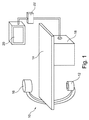
図1は心臓弁置換のための正確な位置決めのための検査装置を持つカテーテル検査室において使用するためのX線画像システム10を概略的に示す。検査装置はX線放射を発生させるために設けられるX線放射線源12を持つX線画像取得装置を有する。検査対象を受けるためにテーブル14が設けられる。さらに、X線画像検出モジュール16がX線放射線源12の反対側に位置し、すなわち放射線手順中、被験者はX線放射線源12と検出モジュール16の間に位置する。後者はデータ処理ユニット若しくは計算ユニット18にデータを送信し、これは検出モジュール16と放射線源12の両方に接続される。計算ユニット18はカテーテル検査室内の空間を節約するためにテーブル14の下に位置する。勿論、これは異なる部屋など、異なる場所に位置することもできる。さらに表示装置20がテーブル14の近くに配置され、X線画像システムを操作する人、すなわち心臓専門医若しくは心臓外科医などの臨床医に情報を表示する。好適には表示装置20は検査状況に応じて個々の調節を可能にするために可動式に取り付けられる。また、インターフェースユニット22がユーザによって情報を入力するために構成される。基本的に、画像検出モジュール16は被験者をX線放射にさらすことによって画像を生成し、該画像はデータ処理ユニット18においてさらに処理される。いわゆるC型X線画像取得装置の実施例が示されることが留意される。勿論、本発明は他の種類のX線画像取得装置にも関する。本発明にかかる手順は以下により詳細に記載される。
FIG. 1 schematically illustrates an
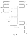
図2は本発明にかかるステップのフローチャートを概略的に示す。第1の取得ステップ24において、血管関心領域の少なくとも1つのX線画像が注入された造影剤で取得される。識別ステップ26において、少なくとも1つの取得画像内の血管情報データが識別される。第1の検出ステップ28において、血管関心領域内の血管の第1の石灰化特徴が少なくとも1つの取得画像中で検出される。さらに、生成ステップ30において、血管表現が血管情報データと検出された石灰化特徴とを用いて生成される。さらに、第2の取得ステップ32において、少なくとも1つの現在の蛍光透視画像が血管関心領域について取得される。そして、第2の検出ステップ34において、血管の第2の石灰化特徴が少なくとも1つの現在の蛍光透視画像中の血管関心領域内で検出され、第2の石灰化特徴は第1の石灰化特徴に対応する。
FIG. 2 schematically shows a flowchart of the steps according to the invention. In a
言い換えれば、第1及び第2の石灰化特徴は同じ石灰化特徴であり、ただし異なる画像中にある。勿論、第1及び第2の石灰化特徴という語は各々1つ以上の石灰化特徴を有することができる。 In other words, the first and second calcification features are the same calcification features, but in different images. Of course, the terms first and second calcification features can each have one or more calcification features.
レジストレーションステップ36において、血管表現が蛍光透視画像とレジストレーションされ、石灰化特徴はレジストレーションステップ36のために使用される。さらに、生成ステップ38において、血管表現を少なくとも1つの蛍光透視画像と合成することによって合成画像が生成される。そして、表示ステップ40において、合成画像が例えばディスプレイ20などのディスプレイ上に表示される。
In
一実施形態例によれば、血管表現は血管の生成モデルである。 According to an example embodiment, the blood vessel representation is a blood vessel generation model.
一実施形態例によれば、PAVの場合、モデルは例えば弁尖平面の画像平面内の投影、及び例えば弁の中心軸の(画像平面内の)投影を含む簡易表現によって構成されることもできる。 According to an example embodiment, in the case of PAV, the model can also consist of a simplified representation including, for example, the projection of the leaflet plane in the image plane and the projection of the central axis of the valve (in the image plane) .
一般的に、血管表現は装置の正確な配置のために十分な情報を与えるものでなければならず、合成画像を過剰な情報でいっぱいにすることを避け、インターベンショナリストを混乱させることを避けるように十分に単純でなければならない。 In general, the vascular representation should give enough information for the correct placement of the device, avoid filling the composite image with too much information and confusing the interventionist. Must be simple enough to avoid.
PAVの場合、プロテーゼ角度及び挿入範囲が正確に制御されるべきである。角度はプロテーゼの回転軸を弁中心軸に平行に向けることによって制御されることができる。挿入範囲は弁尖平面に対して弁中心を位置付けることによって制御されることができる。 In the case of PAV, the prosthesis angle and insertion range should be precisely controlled. The angle can be controlled by orienting the rotation axis of the prosthesis parallel to the valve center axis. The insertion range can be controlled by positioning the valve center relative to the leaflet plane.
一実施形態例によれば、第1の取得ステップ24は注入された造影剤で関心領域の画像のシーケンスを取得するステップと、次のステップのために最適なコントラストを持つ画像を選択するステップとを有し、この実施形態は図2にはさらに示されない。
According to an example embodiment, the
図3に示す一実施形態例によれば、注入された造影剤で血管が満たされ、石灰化特徴を見えなくする可能性がある画像を有し、石灰化特徴が見えるように注入された造影剤で血管があまり満たされない画像を有する、画像のシーケンスが取得される。このプロセスは大動脈造影112とも称される。さらに、検出ステップ114において、参照画像中の一定数の大動脈基部候補輪郭若しくは選択輪郭が時間t0において検出される。好適には、このステップを難し過ぎないようにする候補若しくは選択が使用される。3Dデータが関係するとき、それらは候補発見のために使用されることができる。
According to an example embodiment shown in FIG. 3, a blood vessel is filled with an injected contrast agent and has an image that may cause the calcification feature to be invisible, with the image injected so that the calcification feature is visible. A sequence of images is acquired having an image that does not fill the vessel well with the agent. This process is also referred to as
候補輪郭のさらなるトラッキングステップ116において、シーケンスの画像は造影剤がなくなり始めるまでトラックされる。
In a
このトラッキングは因果的に(つまり増加する画像時刻に沿って)又は非因果的に(つまり減少する時刻に沿って)起こることができる。 This tracking can occur causally (ie along increasing image times) or non-causally (ie along decreasing times).
これは時間トラック上のある時点において起こり、この時間はt1とあらわされる。トラッキングフェーズ中に輪郭をリンクする全空間関係が記録される(図3にはさらに示さない)。 This occurs at some point on the time track, and this time is denoted t 1 . The total spatial relationship that links the contours during the tracking phase is recorded (not shown further in FIG. 3).
さらに、例えばフィルタリング及びヒストグラム法を用いて、時間軸に沿った造影剤量のモニタリングにより、時間t1における造影剤が消えていく瞬間に対して決定ステップ118が実行される。
Further, a
さらに、識別ステップ120において、時間t1において、候補輪郭に近い石灰化候補スポット、若しくは言い換えれば石灰化特徴が識別され、相似運動で外見的にアニメーション化される。勿論、この運動は、例えばハイパーペーシングの場合など、振動を含み得る。時間t1において石灰化スポットが見え始めるが、候補輪郭はそのフレームに至るまでなおトラック可能であることが留意されなければならない。
Further, in the
さらに、リバーストラッキングステップ122において、輪郭をリンクする空間関係が、例えばフォワードトラッキング法で石灰化特徴に適用される。
Furthermore, in the
この理由は以下に記載される。輪郭はt0からt1までトラックされているため、及び時間t1における石灰化候補スポットはt1候補輪郭に関して位置特定されることができるため、t1における見える候補と、t0におけるそれらの隠れた対応物との間の空間関係を決定することが可能であり、そのためリバーストラッキングという語が使用される。しかしながら、これは時間t0における参照大動脈造影図に対するランドマークのセットSA(t0)の定義も可能にする。 The reason for this is described below. Because the contour is tracked from t 0 to t 1 and because the calcification candidate spot at time t 1 can be located with respect to the t 1 candidate contour, the visible candidates at t 1 and their at t 0 It is possible to determine the spatial relationship between the hidden counterparts, so the term reverse tracking is used. However, this also allows the definition of a set of landmarks S A (t 0 ) for the reference aortogram at time t 0 .
従って、リバーストラッキングステップ122の後、決定ステップ124において、ランドマークSA(t0)が決定される。本発明によれば、上記と同じようなステップは例えば蛍光ライブ画像において再現されることができる。
Therefore, after the
図3に示す実施形態例によれば、血管関心領域の少なくとも1つの現在の蛍光透視画像が取得ステップ126において取得される。さらに、識別ステップ128において、石灰化特徴若しくは石灰化候補スポットが時間tにおいて、例えば蛍光画像のシーケンスの場合は蛍光シーケンスに沿って、識別される。基準が造影剤をアスペクトとして含む、ランドマークSAの検索に加えて、これらのスポットの形状と動きが含まれる可能性がある。石灰化スポットが識別されると、さらなる識別ステップ130において、時間tにおける各蛍光画像に対するランドマークSF(t)のセットが識別されることができる。
According to the example embodiment shown in FIG. 3, at least one current fluoroscopic image of the vascular region of interest is acquired in
ランドマークSA(t0)及びランドマークSF(t)がステップ124及び130において各々決定されると、例えばインターベンション手術中に、取得ステップ126において取得された蛍光画像と画像取得ステップ112の取得画像をレジストレーションすることが可能である。
When the landmark S A (t 0 ) and the landmark S F (t) are determined in
改良された画像を提供するために、レジストレーションステップ132において、定義済の幾何学変換G(t0,t)が、参照画像を時点tにおけるライブ画像と空間対応させるために使用されることができ、あらゆる種類のオーバーレイ及び/又は正確な位置決め方法を可能にする。そしてレジストレーションされ、幾何学変換された画像データはさらなるステップ130において合成され表示されることができる。
To provide an improved image, a predefined geometric transformation G (t 0 , t) is used in
本発明によれば、図1に示す画像取得装置は、注入された造影剤で血管関心領域の少なくとも1つのX線画像を取得し、血管関心領域の少なくとも1つの蛍光透視画像を取得するように構成される。データ処理ユニット18は少なくとも1つの取得画像内の血管情報データを識別し、少なくとも1つの取得画像中の血管関心領域の第1の石灰化特徴を検出し、血管情報データと検出された石灰化特徴とを用いて血管表現を生成するように構成される。データ処理ユニット18はまた、少なくとも1つの現在の蛍光透視画像中の血管関心領域中の血管の第2の石灰化特徴を検出するようにも構成され、第2の石灰化特徴は第1の石灰化特徴に対応する。データ処理ユニット18はまた、血管表現を蛍光透視画像とレジストレーションするようにも構成され、石灰化特徴はレジストレーションのために使用され、血管表現を少なくとも1つの蛍光透視画像と合成することによって合成画像を生成するようにも構成される。表示装置20は合成画像を表示するように構成される。
According to the present invention, the image acquisition device shown in FIG. 1 acquires at least one X-ray image of the vascular region of interest with the injected contrast agent, and acquires at least one fluoroscopic image of the vascular region of interest. Composed. The
一実施例として、関心のある血管は大動脈である。高齢化人口のために心臓弁障害若しくは心臓弁疾患の治療がより重要になっており、こうした疾患は通常、自然心臓弁の置換を要するため、本発明は例えば経皮的心臓弁移植中によりよい情報を心臓専門医若しくは外科医に与える。本発明は大動脈弁の置換に関して例示的に記載されているが、本発明はまた、肺動脈弁、僧帽弁、三尖弁など、他の種類の心臓弁の置換にも焦点を合わせる。勿論、本発明はまた、例えば欠陥のある血管断面を持つ血管領域へのステントの挿入など、他の血管治療にも焦点を合わせる。 As one example, the blood vessel of interest is the aorta. Because of the aging population, the treatment of heart valve disorders or heart valve diseases has become more important and such diseases usually require replacement of natural heart valves, so the present invention may be better for example during percutaneous heart valve transplantation Give information to the cardiologist or surgeon. Although the present invention has been exemplarily described with respect to aortic valve replacement, the present invention also focuses on replacement of other types of heart valves, such as pulmonary valves, mitral valves, and tricuspid valves. Of course, the present invention also focuses on other vascular treatments, such as the insertion of a stent into a vascular region having a defective vascular cross section.
図4において、主血管に関して右側212と左側214とを持つ心臓210が示される。右側212は図中の大静脈上に置かれる。これは右冠状動脈によって血液供給される心臓の部分を指定するはずである。左側の上部に(大動脈)弓218を形成する上行大動脈216が見られ、複数の他の血管220が大動脈216に接続される。そして大動脈216は下方へ通じ、ここで腹腔動脈222及び上腸間膜動脈などの複数のさらなる血管が接続される。さらに、大動脈は腎動脈226と腸骨動脈230へ通じる下腸間膜動脈228とに分かれる。この部分は腹部大動脈とも呼ばれる。心臓への接続点自体、いわば大動脈216の始点は基部232若しくは大動脈基部である。さらに、2つの冠状動脈233が基部領域230に接続される。図4には示されない大動脈心臓弁は基部232に位置する。
In FIG. 4, a
図5において基部232に位置する、大動脈弁の置換などの心臓弁置換のために、弁送達カテーテル234が鼠径部に腸骨動脈230のうちの1つへ挿入され、置換すべき心臓弁に至るまで挿入される。言い換えれば、カテーテル234は、正確な位置決め後に弁が配置される基部領域に達するまで、(大動脈)弓218を通過して大動脈をたどる。
For heart valve replacement, such as aortic valve replacement, located at the base 232 in FIG. 5, a
上記方法ステップに従って生成される合成画像の表示を外科医に与えることによって、外科医は人工心臓弁を正しい位置に据えるためにカテーテル若しくは別の位置決め器具のそれぞれ位置特定若しくは位置決めについての改良された若しくは改善された情報を与えられる。レジストレーション特徴として、図4に概略的にしか示されていない石灰化スポット236を用いることによって、血管表現を現在取得された画像、例えば蛍光透視画像と合成することが可能である。血管表現、例えば大動脈造影は外科医にロードマップのようなものを与え、蛍光透視画像はカテーテル234若しくは他のインターベンション器具の位置特定に必要な情報を提供する。従って、表示される合成画像は外科医若しくは心臓専門医に人工弁の正確な配置に必要な情報を与える。実際の、各々現在の情報に対して、所定間隔で蛍光透視画像取得を繰り返すことが可能である。通常、蛍光透視画像取得ステップは造影剤の使用なしに行われる。外科医に本発明にかかる合成画像を与えることによって、術中に使用される造影剤の量を減らすことができ、これは例えば肝臓障害を持つ患者にとって大きな安心を意味する。
By providing the surgeon with a display of the composite image generated according to the above method steps, the surgeon may have improved or improved the positioning or positioning of the catheter or another positioning device, respectively, to place the prosthetic heart valve in the correct position. Given information. By using a
勿論、血管造影図若しくは大動脈造影図取得を、及び、血管表現若しくは大動脈基部表現を所定速度で、又は、例えば手術が実際に予想されるよりも長くかかる場合、実際の必要性に応じて、生成する若しくはモデル化するための次のステップを繰り返すことも可能である。 Of course, angiograms or aortic angiogram acquisition and vascular or aortic root representations are generated at a given rate, or if the surgery takes longer than expected, for example, depending on actual needs It is also possible to repeat the following steps to do or model.
一実施形態例によれば、血管情報データと検出された石灰化特徴を用いて血管表現を生成するステップは、血管情報データと検出された石灰化特徴を用いて血管表現をモデル化するステップを有する。 According to an example embodiment, generating the blood vessel representation using the blood vessel information data and the detected calcification feature includes modeling the blood vessel representation using the blood vessel information data and the detected calcification feature. Have.
一実施例として、図6は大動脈造影図のために使用される注入画像を示す。造影剤の使用により、大動脈基部312が画像の中心付近に見える。さらに、注入カテーテル314が見られ、これによって造影剤が関心領域に注入される。さらに、胸骨クリップ316、脊椎要素318、若しくは超音波プローブ320などの他の特徴も図6における注入画像内に見えている。
As an example, FIG. 6 shows an infusion image used for an aortogram. By using the contrast agent, the
図6の注入画像は例えば全大動脈造影シーケンスの複数画像のシーケンスからの1画像であり得ることが留意されるべきである。図6は造影剤で十分に満たされた、十分に満たされた状態を持つ大動脈基部を示し、石灰化スポット322は図6に示す画像においてほとんど見えない。それにもかかわらず、石灰化特徴322は造影剤がなくなり始める画像(図示せず)において見える。
It should be noted that the injected image of FIG. 6 can be, for example, one image from a sequence of multiple images of the entire aortic imaging sequence. FIG. 6 shows a well-filled aortic base that is fully filled with contrast agent, and the
これらの石灰化特徴322が検出され、これは手動で若しくは自動的に実行されることができる。図6で見えている、検出された大動脈基部輪郭をバックトラッキングする間、バックトラッキングフェーズ中に輪郭をリンクする空間関係が記録され、石灰化特徴322はその空間関係に関しても知られる。言い換えれば、石灰化特徴322がシーケンスの全画像において見えていなくても、石灰化特徴322は、石灰化特徴322がほとんどの場合見えない画像中で見えている大動脈基部輪郭に固定関係を持つので、石灰化特徴322の正確な位置を知ることが可能である。一方、例えばカテーテル先端若しくは生検針、又は他の装置は、血管内の装置の位置決めが絶えず変化し、従って大まかな位置情報しか提供せず、必要な正確さを提供しない。
These calcification features 322 are detected and can be performed manually or automatically. While backtracking the detected aortic base contour, visible in FIG. 6, the spatial relationship linking the contour during the backtracking phase is recorded, and the
実際のインターベンション手術中、非注入画像が例えば蛍光透視下で取得され、その一実施例が図7に示される。ここで、胸骨クリップ316、脊椎318若しくは超音波プローブ320などの付加的な特徴に加えて、カテーテル314もまた示されるが、カテーテルの位置決めはその間に変わっている可能性がある。
During actual interventional surgery, non-injected images are acquired, for example under fluoroscopy, an example of which is shown in FIG. Here, in addition to additional features such as
図6に示す大動脈造影図の情報と、図7に示す蛍光透視法で提供される現在の情報とを合成するために、大動脈石灰化特徴322が図7の画像中で検出され、合成すること若しくは合成画像を生成することができるようにするためにレジストレーションプロセスのために使用され、その一実施例が図8に示される。図6における合成画像は、血管情報のみを明確に視覚化するためにバックグラウンドが減算されている画像である、血管造影図としても知られる、図6に示す画像データのさらなる強調画像を有することが留意される。
The
本発明にかかる方法は人工レジストレーションランドマークなしに正確なレジストレーションを画像に提供し、この結果は画像上で容易に見られる。石灰化特徴若しくはスポットがリアルタイム画像においてマスクされる場合、提案されるレジストレーション法が本当に関与するかどうかを決定することが可能である。 The method according to the present invention provides an accurate registration to an image without artificial registration landmarks, and the result is easily seen on the image. If calcification features or spots are masked in the real-time image, it can be determined whether the proposed registration method is really involved.
加えて、正確な位置決めのための一実施形態例が図9から15を参照して記載される。上述の通り、まず、注入画像を有する一連の画像が注入期間中に取得され、これは例えば図9に示す通り大動脈造影図における注入画像412をもたらす。一連の画像は大動脈造影図において非注入画像も有し、非注入画像の一実施例414が図10に示される。
In addition, an example embodiment for accurate positioning is described with reference to FIGS. As described above, a series of images with infusion images are first acquired during the infusion period, which results in an
非注入画像は石灰化416を識別するために使用され、これらは容易な理解のために円418で示される。石灰化416若しくは石灰化特徴は、例えば大動脈石灰化である。
Non-injected images are used to identify
次に、石灰化416が非注入画像から注入画像へトラックされ、これは図11及び12に概略的に示される。トラッキングは図11の画像中の各位置につながる矢印420で示され、この位置は各々十字422で示される。
Next,
これはまた3Dインターベンション前ステップにおいて検出される石灰化に基づくか又はサポートされてもよい。 This may also be based on or supported by calcification detected in the pre-3D intervention step.
さらに、図13に示す通り、直線426で示される大動脈弁平面424、及び点線430で示される中心軸428が識別される。これは2Dデータから直接、又はインターベンション前/周辺3Dデータから達成されることができる。後者の場合、大動脈弁平面と中心軸はまず手動若しくは自動手段のいずれかを通して3Dで決定され、3Dデータセットはまた、3D及び2Dで存在する大動脈基部特徴に基づいて図13の2D大動脈造影図とレジストレーションされ、最後に、レジストレーションされた3D大動脈弁平面と中心軸は2D大動脈造影図に投影され、こうして2D弁平面424と中心軸428を作り出す。
Furthermore, as shown in FIG. 13, an
そして、平面424と中心軸428は図14に概略的に示す通り大動脈造影図トラック済石灰化に対して幾何学的に関連付けられる。これは石灰化422に平面424と軸428をリンクする順方向幾何学変換を定義する。
The
さらに、図15は、蛍光ライブ画像中のトラックされた石灰化からのレジストレーションされた平面424'と、レジストレーションされた中心軸428'が、空間データにも従って変換されることを示す。これは上述の順方向幾何学変換を逆にすることによって、及び結果として生じる逆変換を適用することによって達成され、これはトラックされた石灰化422'を新たに推定される平面424'と軸428'にリンクする。図15はまた挿入された経皮弁432も示すことが留意される。
Furthermore, FIG. 15 shows that the registered
図16から18は本発明のさらなる理解のために図6から8の図に加えてX線画像を使用する写真画像を示す。 FIGS. 16 to 18 show photographic images using X-ray images in addition to the views of FIGS. 6 to 8 for further understanding of the invention.
図19から25は本発明のさらなる理解のために図9から15の図に加えてX線画像を用いる写真画像を示す。 19 to 25 show photographic images using X-ray images in addition to the views of FIGS. 9 to 15 for further understanding of the present invention.
本発明は図面と前述の説明において詳細に図示され記載されているが、かかる図示と記載は説明若しくは例示であって限定ではないと見なされるものとする。本発明は開示された実施形態に限定されない。開示された実施形態への他の変更は、図面、開示及び従属クレームの考察から、請求された発明を実践する上で当業者によって理解されもたらされることができる。 While the invention has been illustrated and described in detail in the drawings and foregoing description, such illustration and description are to be considered illustrative or exemplary and not restrictive; The invention is not limited to the disclosed embodiments. Other modifications to the disclosed embodiments can be understood and effected by those skilled in the art in practicing the claimed invention, from a consideration of the drawings, disclosure, and dependent claims.
クレーム中、"有する"という語は他の要素若しくはステップを除外せず、不定冠詞"a"若しくは"an"は複数を除外しない。単一のプロセッサ若しくは他のユニットがクレーム中に列挙された複数の項目の機能を満たしてもよい。特定の手段が相互に異なる従属クレームに列挙されるという単なる事実は、これらの手段の組み合わせが有利に使用されることができないことを示すものではない。 In the claims, the word “comprising” does not exclude other elements or steps, and the indefinite article “a” or “an” does not exclude a plurality. A single processor or other unit may fulfill the functions of the items listed in the claims. The mere fact that certain measures are recited in mutually different dependent claims does not indicate that a combination of these measured cannot be used to advantage.
コンピュータプログラムは他のハードウェアと一緒に若しくはその一部として供給される光記憶媒体若しくは固体媒体などの適切な媒体上に保存及び/又は分散され得るが、インターネット又は他の有線若しくは無線通信システムなどを介して他の形式で分散されてもよい。 The computer program may be stored and / or distributed on any suitable medium, such as an optical storage medium or solid medium supplied with or as part of other hardware, such as the Internet or other wired or wireless communication system It may be distributed in other forms via
クレーム中の任意の参照符号は範囲を限定するものと解釈されてはならない。 Any reference signs in the claims should not be construed as limiting the scope.
Claims (13)
‐少なくとも1つのX線画像取得装置と、
‐データ処理ユニットと、
‐表示装置とを有し、
前記X線画像取得装置が、注入された造影剤で血管関心領域の少なくとも1つのX線画像を取得し、前記血管関心領域の少なくとも1つの現在の蛍光透視画像を取得し、
前記データ処理ユニットが、前記少なくとも1つの取得画像内の血管情報データを識別し、前記少なくとも1つの取得画像中の前記血管関心領域中の血管の第1の石灰化特徴を検出し、前記血管情報データと前記検出された石灰化特徴とを用いて血管表現を生成し、前記少なくとも1つの現在の蛍光透視画像中の前記血管関心領域中の血管の第2の石灰化特徴を検出し、前記第2の石灰化特徴は前記第1の石灰化特徴に対応し、前記血管表現を前記蛍光透視画像とレジストレーションし、前記石灰化特徴は前記レジストレーションのために使用され、前記血管表現を前記少なくとも1つの蛍光透視画像と合成することによって合成画像を生成し、
前記表示装置が、前記合成画像を表示し、
前記X線画像取得装置が、注入された造影剤で前記血管関心領域の画像のシーケンスを取得し、前記データ処理ユニットが最適なコントラストを持つ画像を選択する、
医用画像装置。 A medical imaging device for accurate positioning for vascular interventional surgery,
-At least one X-ray image acquisition device;
-A data processing unit;
-A display device;
The X-ray image acquisition device acquires at least one X-ray image of a vascular region of interest with an injected contrast agent, acquires at least one current fluoroscopic image of the vascular region of interest;
The data processing unit identifies blood vessel information data in the at least one acquired image, detects a first calcification characteristic of a blood vessel in the blood vessel region of interest in the at least one acquired image, and the blood vessel information Generating a blood vessel representation using the data and the detected calcification feature, detecting a second calcification feature of a blood vessel in the vascular region of interest in the at least one current fluoroscopic image; A calcification feature of 2 corresponds to the first calcification feature, registers the vascular representation with the fluoroscopic image, the calcification feature is used for the registration, Generating a composite image by combining with one fluoroscopic image,
Wherein the display device displays the composite image,
The X-ray image acquisition device acquires a sequence of images of the vascular region of interest with an injected contrast agent, and the data processing unit selects an image having an optimal contrast;
Medical imaging device.
X線画像取得装置が、注入された造影剤で血管関心領域の少なくとも1つのX線画像を取得するステップと、
データ処理ユニットが、前記少なくとも1つの取得画像内の血管情報データを識別するステップと、
前記データ処理ユニットが、前記少なくとも1つの取得画像中の前記血管領域中の血管の第1の石灰化特徴を検出するステップと、
前記データ処理ユニットが、前記血管情報データと前記検出された石灰化特徴とを用いて血管表現を生成するステップと、
前記X線画像取得装置が、前記血管関心領域の少なくとも1つの現在の蛍光透視画像を取得するステップと、
前記データ処理ユニットが、前記少なくとも1つの現在の蛍光透視画像中の前記血管関心領域中の血管の第2の石灰化特徴を検出するステップであって、前記第2の石灰化特徴は前記第1の石灰化特徴に対応する、ステップと、
前記データ処理ユニットが、前記血管表現を前記蛍光透視画像とレジストレーションするステップであって、前記石灰化特徴は前記レジストレーションのために使用される、ステップと、
前記データ処理ユニットが、前記血管表現を前記少なくとも1つの蛍光透視画像と合成することによって合成画像を生成するステップと、
表示装置が、前記合成画像をディスプレイ上に表示するステップとを有する、方法であって、
前記X線画像取得装置が、注入された造影剤で前記血管関心領域の画像のシーケンスを取得し、前記データ処理ユニットが最適なコントラストを持つ画像を選択する、方法。 A method of operating a medical imaging device for accurate positioning for vascular interventional surgery, comprising:
An X-ray image acquisition device acquiring at least one X-ray image of a vascular region of interest with the injected contrast agent;
A data processing unit identifying blood vessel information data in the at least one acquired image;
The data processing unit detecting a first calcification feature of a blood vessel in the blood vessel region in the at least one acquired image;
The data processing unit generates a blood vessel representation using the blood vessel information data and the detected calcification features;
The X-ray image acquisition device acquiring at least one current fluoroscopic image of the vascular region of interest;
The data processing unit detecting a second calcification feature of a blood vessel in the vascular region of interest in the at least one current fluoroscopic image, wherein the second calcification feature is the first calcification feature; Steps corresponding to the calcification characteristics of
The data processing unit registering the blood vessel representation with the fluoroscopic image, wherein the calcification feature is used for the registration;
The data processing unit generates a composite image by combining the blood vessel representation with the at least one fluoroscopic image;
A display device comprising: displaying the composite image on a display ,
The method wherein the X-ray image acquisition device acquires a sequence of images of the vascular region of interest with an injected contrast agent, and the data processing unit selects an image with optimal contrast .
Applications Claiming Priority (3)
| Application Number | Priority Date | Filing Date | Title |
|---|---|---|---|
| EP09305915.2 | 2009-09-29 | ||
| EP09305915 | 2009-09-29 | ||
| PCT/IB2010/054280 WO2011039681A1 (en) | 2009-09-29 | 2010-09-22 | Live registration for vessel treatment |
Publications (2)
| Publication Number | Publication Date |
|---|---|
| JP2013505766A JP2013505766A (en) | 2013-02-21 |
| JP5647251B2 true JP5647251B2 (en) | 2014-12-24 |
Family
ID=43243055
Family Applications (1)
| Application Number | Title | Priority Date | Filing Date |
|---|---|---|---|
| JP2012530397A Active JP5647251B2 (en) | 2009-09-29 | 2010-09-22 | Accurate positioning for vascular interventional surgery |
Country Status (6)
| Country | Link |
|---|---|
| US (1) | US8718349B2 (en) |
| EP (1) | EP2482727B1 (en) |
| JP (1) | JP5647251B2 (en) |
| CN (1) | CN102548478B (en) |
| RU (1) | RU2535608C2 (en) |
| WO (1) | WO2011039681A1 (en) |
Families Citing this family (24)
| Publication number | Priority date | Publication date | Assignee | Title |
|---|---|---|---|---|
| EP2595541B1 (en) * | 2010-07-19 | 2020-09-30 | Koninklijke Philips N.V. | Adaptive roadmapping |
| US8655041B2 (en) * | 2010-09-23 | 2014-02-18 | Siemens Aktiengesellschaft | Automatic detection of contrast injection |
| BR112013019794A2 (en) | 2011-02-07 | 2016-10-25 | Koninkl Philips Nv | medical imaging apparatus for providing an image representation confirming the accurate positioning of an intervention apparatus in vascular intervention procedures, cath lab system, method for providing an image representation confirming the accurate positioning of an intervention apparatus in vascular intervention procedures vascular intervention procedure, computer program and computer readable media |
| BR112013033913A2 (en) * | 2011-04-28 | 2019-09-24 | Koninl Philips Electronics Nv | medical imaging device |
| EP2754126B1 (en) | 2011-11-18 | 2020-07-01 | Koninklijke Philips N.V. | Pairing of an anatomy representation with live images |
| JP6169832B2 (en) * | 2011-11-29 | 2017-07-26 | 東芝メディカルシステムズ株式会社 | X-ray equipment |
| JP2013158372A (en) * | 2012-02-01 | 2013-08-19 | Toshiba Corp | Medical image processing device, medical image processing method and x-ray equipment |
| CN103678837A (en) * | 2012-08-31 | 2014-03-26 | 西门子公司 | Method and device for determining processing remains of target area |
| WO2014072890A1 (en) * | 2012-11-06 | 2014-05-15 | Koninklijke Philips N.V. | Enhancing ultrasound images |
| KR101811817B1 (en) | 2013-02-14 | 2018-01-25 | 세이코 엡슨 가부시키가이샤 | Head mounted display and control method for head mounted display |
| ES2913224T3 (en) * | 2013-03-12 | 2022-06-01 | Lightlab Imaging Inc | Vascular data processing methods and image registration |
| JP6371515B2 (en) * | 2013-11-13 | 2018-08-08 | キヤノン株式会社 | X-ray image processing apparatus, X-ray image processing method, and program |
| EP3071107B1 (en) * | 2013-11-20 | 2018-02-28 | Koninklijke Philips N.V. | Medical image viewing device for navigation in x-ray imaging, medical imaging system and method for providing improved x-ray image navigation information |
| US9311570B2 (en) * | 2013-12-06 | 2016-04-12 | Kabushiki Kaisha Toshiba | Method of, and apparatus for, segmentation of structures in medical images |
| EP3113702B1 (en) * | 2014-02-27 | 2021-03-10 | Koninklijke Philips N.V. | Registration apparatus for interventional procedure |
| JP6359312B2 (en) * | 2014-03-27 | 2018-07-18 | キヤノンメディカルシステムズ株式会社 | X-ray diagnostic equipment |
| CA2960457A1 (en) * | 2014-09-12 | 2016-03-17 | Koninklijke Philips N.V. | Analyzing aortic valve calcification |
| JP6448356B2 (en) * | 2014-12-22 | 2019-01-09 | キヤノン株式会社 | Image processing apparatus, image processing method, image processing system, and program |
| KR102367133B1 (en) * | 2015-02-24 | 2022-02-24 | 삼성전자주식회사 | Medical image apparatus and method for processing medical image |
| US10624597B2 (en) | 2015-02-24 | 2020-04-21 | Samsung Electronics Co., Ltd. | Medical imaging device and medical image processing method |
| CN107347249B (en) | 2015-03-16 | 2021-10-01 | 皇家飞利浦有限公司 | Automatic movement detection |
| CN107920796B (en) * | 2015-07-27 | 2021-10-01 | 皇家飞利浦有限公司 | Medical placement alert |
| JP7167564B2 (en) * | 2018-09-05 | 2022-11-09 | 株式会社島津製作所 | Radiographic device and method of operating the radiographic device |
| EP3643238A1 (en) * | 2018-10-25 | 2020-04-29 | Koninklijke Philips N.V. | Image based guiding of an interventional device |
Family Cites Families (15)
| Publication number | Priority date | Publication date | Assignee | Title |
|---|---|---|---|---|
| US4263916A (en) | 1978-03-27 | 1981-04-28 | University Of Southern California | Image averaging for angiography by registration and combination of serial images |
| RU2043073C1 (en) * | 1992-06-04 | 1995-09-10 | Государственный научно-исследовательский институт авиационных систем | Method and device for digital subtraction angyography |
| WO2001093745A2 (en) | 2000-06-06 | 2001-12-13 | The Research Foundation Of State University Of New York | Computer aided visualization, fusion and treatment planning |
| AU2002348241A1 (en) | 2001-11-24 | 2003-06-10 | Image Analysis, Inc. | Automatic detection and quantification of coronary and aortic calcium |
| US6628743B1 (en) * | 2002-11-26 | 2003-09-30 | Ge Medical Systems Global Technology Company, Llc | Method and apparatus for acquiring and analyzing cardiac data from a patient |
| US7330576B2 (en) | 2003-12-03 | 2008-02-12 | The Board Of Trustees Of The Leland Stanford Junior University | Quantification method of vessel calcification |
| DE102004035980A1 (en) * | 2004-07-23 | 2006-03-16 | Siemens Ag | Method of imaging in interventional intervention |
| US7725165B2 (en) * | 2004-12-07 | 2010-05-25 | M2S, Inc. | Method and apparatus for visualizing anatomical structures |
| WO2008050315A2 (en) * | 2006-10-22 | 2008-05-02 | Paieon Inc. | Method and apparatus for guiding a device in a totally occluded or partly occluded tubular organ |
| US7995824B2 (en) * | 2006-02-10 | 2011-08-09 | University Of Medicine And Dentistry Of New Jersey | Precision subtraction computed tomographic angiography |
| DE102006048606A1 (en) * | 2006-10-13 | 2008-04-17 | Siemens Ag | X-ray image producing method for use in medical field, involves superimposing X-ray image on another X-ray image, and representing X-ray images periodically time-synchronously with body function according to type of film |
| JP5368315B2 (en) * | 2007-01-08 | 2013-12-18 | コーニンクレッカ フィリップス エヌ ヴェ | Imaging system for imaging region of interest with moving object |
| US8781193B2 (en) * | 2007-03-08 | 2014-07-15 | Sync-Rx, Ltd. | Automatic quantitative vessel analysis |
| US20080242977A1 (en) * | 2007-03-30 | 2008-10-02 | General Electric Company | Systems, methods and apparatus for longitudinal/temporal analysis of plaque lesions |
| US8625865B2 (en) * | 2008-04-17 | 2014-01-07 | Paieon Inc. | Method and apparatus for navigating a therapeutic device to a location |
-
2010
- 2010-09-22 JP JP2012530397A patent/JP5647251B2/en active Active
- 2010-09-22 CN CN201080043276.8A patent/CN102548478B/en active Active
- 2010-09-22 US US13/387,234 patent/US8718349B2/en active Active
- 2010-09-22 RU RU2012117601/14A patent/RU2535608C2/en not_active IP Right Cessation
- 2010-09-22 WO PCT/IB2010/054280 patent/WO2011039681A1/en active Application Filing
- 2010-09-22 EP EP10765514A patent/EP2482727B1/en active Active
Also Published As
| Publication number | Publication date |
|---|---|
| US8718349B2 (en) | 2014-05-06 |
| EP2482727B1 (en) | 2013-01-23 |
| JP2013505766A (en) | 2013-02-21 |
| WO2011039681A1 (en) | 2011-04-07 |
| RU2012117601A (en) | 2013-11-10 |
| CN102548478A (en) | 2012-07-04 |
| CN102548478B (en) | 2014-12-03 |
| RU2535608C2 (en) | 2014-12-20 |
| EP2482727A1 (en) | 2012-08-08 |
| US20120177277A1 (en) | 2012-07-12 |
Similar Documents
| Publication | Publication Date | Title |
|---|---|---|
| JP5647251B2 (en) | Accurate positioning for vascular interventional surgery | |
| EP2672895B1 (en) | Medical imaging device for providing an image representation supporting the accurate positioning of an invention device in vessel intervention procedures | |
| JP5718820B2 (en) | Automatic road mapping for heart valve replacement | |
| JP6175073B2 (en) | Real-time display of vascular view for optimal device navigation | |
| JP5503284B2 (en) | Motion compensated coronary blood flow from projection imaging | |
| JP6122864B2 (en) | Pair live image with anatomical structure display | |
| US20100061611A1 (en) | Co-registration of coronary artery computed tomography and fluoroscopic sequence | |
| US10052032B2 (en) | Stenosis therapy planning | |
| JP2017518786A (en) | Device for determining a specific position of a catheter | |
| JP6509446B2 (en) | Synthetic representation of vascular structure | |
| JP2008526420A (en) | Image processing system and method for image alignment | |
| CN107174263A (en) | For the method for the view data for gathering and handling check object | |
| JP6828083B2 (en) | Automatic motion detection | |
| US20120022366A1 (en) | Registration of aorta to patient via two 2d images for placement of a stent | |
| US9036880B2 (en) | High-resolution three-dimensional medical imaging with dynamic real-time information | |
| JP6876200B2 (en) | Alignment of static preoperative planning data with respect to dynamic intraoperative segmentation data | |
| EP3461411A1 (en) | Augmented anatomical map | |
| Jelnin et al. | Use of computed tomography to guide mitral interventions | |
| Kliger et al. | Fusion Imaging for TAVR |
Legal Events
| Date | Code | Title | Description |
|---|---|---|---|
| A621 | Written request for application examination |
Free format text: JAPANESE INTERMEDIATE CODE: A621 Effective date: 20130918 |
|
| A977 | Report on retrieval |
Free format text: JAPANESE INTERMEDIATE CODE: A971007 Effective date: 20140212 |
|
| A131 | Notification of reasons for refusal |
Free format text: JAPANESE INTERMEDIATE CODE: A131 Effective date: 20140225 |
|
| A521 | Request for written amendment filed |
Free format text: JAPANESE INTERMEDIATE CODE: A523 Effective date: 20140512 |
|
| TRDD | Decision of grant or rejection written | ||
| A01 | Written decision to grant a patent or to grant a registration (utility model) |
Free format text: JAPANESE INTERMEDIATE CODE: A01 Effective date: 20141010 |
|
| A61 | First payment of annual fees (during grant procedure) |
Free format text: JAPANESE INTERMEDIATE CODE: A61 Effective date: 20141106 |
|
| R150 | Certificate of patent or registration of utility model |
Ref document number: 5647251 Country of ref document: JP Free format text: JAPANESE INTERMEDIATE CODE: R150 |
|
| R250 | Receipt of annual fees |
Free format text: JAPANESE INTERMEDIATE CODE: R250 |
|
| R250 | Receipt of annual fees |
Free format text: JAPANESE INTERMEDIATE CODE: R250 |
|
| R250 | Receipt of annual fees |
Free format text: JAPANESE INTERMEDIATE CODE: R250 |
|
| R250 | Receipt of annual fees |
Free format text: JAPANESE INTERMEDIATE CODE: R250 |
|
| R250 | Receipt of annual fees |
Free format text: JAPANESE INTERMEDIATE CODE: R250 |
|
| R250 | Receipt of annual fees |
Free format text: JAPANESE INTERMEDIATE CODE: R250 |
|
| R250 | Receipt of annual fees |
Free format text: JAPANESE INTERMEDIATE CODE: R250 |