JP5604246B2 - Camera blade drive - Google Patents
Camera blade drive Download PDFInfo
- Publication number
- JP5604246B2 JP5604246B2 JP2010217727A JP2010217727A JP5604246B2 JP 5604246 B2 JP5604246 B2 JP 5604246B2 JP 2010217727 A JP2010217727 A JP 2010217727A JP 2010217727 A JP2010217727 A JP 2010217727A JP 5604246 B2 JP5604246 B2 JP 5604246B2
- Authority
- JP
- Japan
- Prior art keywords
- blade
- drive ring
- coil
- permanent magnet
- camera
- Prior art date
- Legal status (The legal status is an assumption and is not a legal conclusion. Google has not performed a legal analysis and makes no representation as to the accuracy of the status listed.)
- Expired - Fee Related
Links
Images


Classifications
-
- G—PHYSICS
- G03—PHOTOGRAPHY; CINEMATOGRAPHY; ANALOGOUS TECHNIQUES USING WAVES OTHER THAN OPTICAL WAVES; ELECTROGRAPHY; HOLOGRAPHY
- G03B—APPARATUS OR ARRANGEMENTS FOR TAKING PHOTOGRAPHS OR FOR PROJECTING OR VIEWING THEM; APPARATUS OR ARRANGEMENTS EMPLOYING ANALOGOUS TECHNIQUES USING WAVES OTHER THAN OPTICAL WAVES; ACCESSORIES THEREFOR
- G03B9/00—Exposure-making shutters; Diaphragms
- G03B9/08—Shutters
- G03B9/10—Blade or disc rotating or pivoting about axis normal to its plane
- G03B9/18—More than two members
-
- G—PHYSICS
- G02—OPTICS
- G02F—OPTICAL DEVICES OR ARRANGEMENTS FOR THE CONTROL OF LIGHT BY MODIFICATION OF THE OPTICAL PROPERTIES OF THE MEDIA OF THE ELEMENTS INVOLVED THEREIN; NON-LINEAR OPTICS; FREQUENCY-CHANGING OF LIGHT; OPTICAL LOGIC ELEMENTS; OPTICAL ANALOGUE/DIGITAL CONVERTERS
- G02F1/00—Devices or arrangements for the control of the intensity, colour, phase, polarisation or direction of light arriving from an independent light source, e.g. switching, gating or modulating; Non-linear optics
-
- G—PHYSICS
- G03—PHOTOGRAPHY; CINEMATOGRAPHY; ANALOGOUS TECHNIQUES USING WAVES OTHER THAN OPTICAL WAVES; ELECTROGRAPHY; HOLOGRAPHY
- G03B—APPARATUS OR ARRANGEMENTS FOR TAKING PHOTOGRAPHS OR FOR PROJECTING OR VIEWING THEM; APPARATUS OR ARRANGEMENTS EMPLOYING ANALOGOUS TECHNIQUES USING WAVES OTHER THAN OPTICAL WAVES; ACCESSORIES THEREFOR
- G03B9/00—Exposure-making shutters; Diaphragms
- G03B9/02—Diaphragms
- G03B9/06—Two or more co-operating pivoted blades, e.g. iris type
-
- G—PHYSICS
- G03—PHOTOGRAPHY; CINEMATOGRAPHY; ANALOGOUS TECHNIQUES USING WAVES OTHER THAN OPTICAL WAVES; ELECTROGRAPHY; HOLOGRAPHY
- G03B—APPARATUS OR ARRANGEMENTS FOR TAKING PHOTOGRAPHS OR FOR PROJECTING OR VIEWING THEM; APPARATUS OR ARRANGEMENTS EMPLOYING ANALOGOUS TECHNIQUES USING WAVES OTHER THAN OPTICAL WAVES; ACCESSORIES THEREFOR
- G03B9/00—Exposure-making shutters; Diaphragms
- G03B9/08—Shutters
- G03B9/10—Blade or disc rotating or pivoting about axis normal to its plane
- G03B9/18—More than two members
- G03B9/20—More than two members each moving in a single direction first to open and then to reclose
-
- H—ELECTRICITY
- H04—ELECTRIC COMMUNICATION TECHNIQUE
- H04N—PICTORIAL COMMUNICATION, e.g. TELEVISION
- H04N23/00—Cameras or camera modules comprising electronic image sensors; Control thereof
- H04N23/50—Constructional details
- H04N23/55—Optical parts specially adapted for electronic image sensors; Mounting thereof
Description
本発明は、カメラのシャッター羽根、絞り羽根等の羽根部材を駆動するカメラ用羽根駆動装置に関するものである。 The present invention relates to a camera blade driving device for driving blade members such as shutter blades and diaphragm blades of a camera.
従来、この種の発明には、放射状に多極磁化された円環状に形成されるとともにその多極磁化された面に溝カムを有する永久磁石ロータと、該ロータを間に挟むようにして配設された二つのステータユニットと、前記溝カムに係合する羽根部材とを備え、前記ステータユニットへの通電によって永久磁石ロータを回転させ、前記溝カムによって羽根部材を開閉動作させるようにしたものがある(例えば、特許文献1参照)。
この従来技術によれば、前記ステータユニットに供給されるパルス電力の制御によって、前記永久磁石ロータを所定角度回転させて、前記羽根部材を所望とする開口量に調整することができる。
Conventionally, in this type of invention, a permanent magnet rotor that is formed in an annular shape that is radially multipolarly magnetized and has a groove cam on the multipolarly magnetized surface, and a rotor sandwiched between the rotors are disposed. There are two stator units and a blade member that engages with the groove cam, and the permanent magnet rotor is rotated by energizing the stator unit, and the blade member is opened and closed by the groove cam. (For example, refer to Patent Document 1).
According to this prior art, by controlling the pulse power supplied to the stator unit, the permanent magnet rotor can be rotated by a predetermined angle to adjust the blade member to a desired opening amount.
しかしながら、前記従来技術では、多極磁化された円環状のロータ、及び二つのステータを用いることや、前記ロータ面への溝加工等、複雑な構成や加工を要するため、コストの高騰を招く上、全体構成が大型化し易い。
また、前記従来技術では、非通電時に羽根部材を定位置に保持することができず、デジタルカメラやデジタルビデオカメラに適用する上で改善の余地があった。すなわち、デジタルカメラやデジタルビデオカメラにおいては、CCD(Charge Coupled Device:電荷結合素子)やCMOS(Complementary Metal Oxide Semiconductor:相補型金属酸化膜半導体)等を保護する観点から、電源投入前の初期状態では、羽根部材が全閉状態であることが好ましい。しかし、前記従来技術では、非通電時に羽根部材を全閉状態に保持することができなかった。
However, the conventional technique requires a complicated configuration and processing such as the use of a multi-pole magnetized annular rotor and two stators, and groove processing on the rotor surface. The overall configuration is easy to increase in size.
In the prior art, the blade member cannot be held at a fixed position when no power is supplied, and there is room for improvement in application to a digital camera or a digital video camera. In other words, in digital cameras and digital video cameras, from the viewpoint of protecting CCD (Charge Coupled Device), CMOS (Complementary Metal Oxide Semiconductor), etc., in the initial state before power-on The blade member is preferably in a fully closed state. However, in the prior art, the blade member could not be held in the fully closed state when not energized.
本発明は上記従来事情に鑑みてなされたものであり、その課題とする処は、小型で簡素な構造により羽根部材を動作させることができる上、その羽根部材を非通電時には定位置に保持することができるカメラ用羽根駆動装置を提供することである。 The present invention has been made in view of the above-described conventional circumstances, and the problem is that the blade member can be operated with a small and simple structure, and the blade member is held at a fixed position when not energized. It is an object to provide a blade driving device for a camera.
上記課題を解決するための技術的手段は、光路用の開口部を有する地板と、該地板に支持されて前記開口部を開閉するように動作する羽根部材と、前記地板に対し回動するように設けられた駆動リングとを備え、回動する前記駆動リングに連動させて前記羽根部材を動作するようにしたカメラ用羽根駆動装置において、
前記駆動リングに、永久磁石を設け、
前記地板の駆動リング側の面に、通電することにより電磁力を発生させるコイルを設けるとともに、同地板における前記駆動リング側の面とは反対側の面に、前記永久磁石を吸引する磁性部材を設け、該コイルの非通電時に前記永久磁石と前記磁性部材との間に生じる磁気力により前記駆動リングを所定位置に保持するようにしたことを特徴とする。
Technical means for solving the above-described problems include a ground plate having an opening for an optical path, a blade member that is supported by the ground plate and operates to open and close the opening, and rotates with respect to the ground plate. In the camera blade drive device provided with the drive ring provided to the camera, the blade member is operated in conjunction with the rotating drive ring,
A permanent magnet is provided on the drive ring,
The surface of the drive ring side of the base plate, provided with a coil for generating an electromagnetic force by energizing, on the opposite side to the drive ring side surface in where she plate, magnetic member for attracting the permanent magnet The drive ring is held in a predetermined position by a magnetic force generated between the permanent magnet and the magnetic member when the coil is not energized.
また、特に好ましい具体的手段としては、前記コイルの非通電時に、前記永久磁石が前記磁性部材に吸引されて、前記羽根部材が全閉状態又は全開状態に保持されるようにする。 Further, as a particularly preferable specific means, when the coil is not energized, the permanent magnet is attracted to the magnetic member so that the blade member is held in a fully closed state or a fully opened state.
さらに、全閉状態又は全開状態の羽根部材の静止安定性を向上するためには、前記コイルの非通電時に、前記永久磁石が前記磁性部材に吸引されるとともに、前記羽根部材の閉鎖方向又は開放方向の動作が、前記地板に設けられた規制部により規制されて、前記羽根部材が全閉状態又は全開状態に保持されるようにする。 Further, in order to improve the stationary stability of the fully closed or fully opened blade member, the permanent magnet is attracted to the magnetic member when the coil is not energized, and the blade member is closed or opened. The operation in the direction is regulated by a regulating part provided on the base plate so that the blade member is held in a fully closed state or a fully opened state.
さらに、比較的小型な構造によって駆動リングの回転トルクを増強するためには、前記永久磁石、前記コイル及び前記磁性部材を、前記駆動リングの外周に沿って複数組設ける。 Furthermore, in order to increase the rotational torque of the drive ring with a relatively small structure, a plurality of sets of the permanent magnet, the coil, and the magnetic member are provided along the outer periphery of the drive ring.
さらに、駆動リングの回転バランスを良好にするためには、複数組の前記永久磁石、前記コイル及び前記磁性部材のうち、少なくとも一組と他の一組とは、前記開口部を挟む位置であって且つ前記羽根部材の支持箇所に干渉しない位置に設けられる。 Further, in order to improve the rotational balance of the drive ring, at least one set and the other set of the plurality of sets of the permanent magnet, the coil, and the magnetic member are positions that sandwich the opening. And it is provided in the position which does not interfere with the support location of the said blade member.
本発明は、以上説明したように構成されているので、以下に記載されるような作用効果を奏する。
コイルへの通電状態には、コイルに発生する電磁力によって駆動リング及び永久磁石が回動するため、その回動する駆動リングに連動させて、羽根部材を動作させることができる。また、コイルへの非通電状態には、永久磁石が磁性部材に吸引されるため、駆動リング及び羽根部材を所定位置に保持することができる。
よって、小型で簡素な構造により、羽根部材を動作させることができる上、その羽根部材を非通電時には定位置に保持することができる。
Since the present invention is configured as described above, the following effects can be obtained.
In the energized state of the coil, the drive ring and the permanent magnet are rotated by the electromagnetic force generated in the coil. Therefore, the blade member can be operated in conjunction with the rotating drive ring. Further, since the permanent magnet is attracted by the magnetic member when the coil is not energized, the drive ring and the blade member can be held at predetermined positions.
Therefore, the blade member can be operated with a small and simple structure, and the blade member can be held at a fixed position when the power is not supplied.
以下、本発明の実施の形態を図面に基づいて説明する。
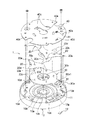
図1〜6は、本発明に係るカメラ用羽根駆動装置をカメラ用絞り装置に適用した一例を示している。
カメラ用羽根駆動装置1は、光路となる開口部10aを有する地板10と、該地板10に支持されて前記開口部10aを開閉するように動作する複数(図示例によれば5つ)の羽根部材20と、地板10に対し回動するように設けられた駆動リング30と、地板10との間に羽根部材20及び駆動リング30を挟むようにして設けられたカバー部40とを備え、回動する駆動リング30に連動させて複数の羽根部材20を開閉動作するように構成される。
そして、このカメラ用羽根駆動装置1は、地板10にコイル11及び磁性部材12を設けるとともに、駆動リング30に永久磁石31を設けており、コイル11の通電時には、コイル11と永久磁石31との間に作用する電磁力によって駆動リング30を回動させ、コイル11の非通電時には、永久磁石31と磁性部材12との間の磁気吸引力によって駆動リング30を所定位置に保持するようにしている。
Hereinafter, embodiments of the present invention will be described with reference to the drawings.
1 to 6 show an example in which the camera blade driving device according to the present invention is applied to a camera diaphragm device.
The camera
The camera
各構成要素について詳細に説明すれば、地板10は、合成樹脂材料からなり、中心部に光路となる開口部10aを有する円盤状に形成される。
この地板10の一方の面における開口部10aの周りには、駆動リング30の回動軸として作用する環状軸10bと、駆動リング30の摩擦抵抗を軽減するための環状レール10cが設けられる。
環状軸10bは、開口部10aの内縁に沿って光軸方向へ突出する環状の突起であり、駆動リング30の内周面と嵌り合って、駆動リング30を回動自在に支持する。
環状レール10cは、環状突起11の周囲に設けられた環状の突起であり、駆動リング30に対し、径方向において部分的に接触して摩擦抵抗を軽減する。この環状レール10cは、周方向に間隔を置いて配設された複数の突起に置換することも可能である。
If it demonstrates in detail about each component, the
Around the
The
The
さらに、地板10における環状レール10cの周囲には、羽根部材20を環装するための支持軸10dや、羽根部材20の開閉動作を規制するための2種類の規制部10e,10f(図2,4及び5参照)が形成されている。
Further, around the
支持軸10dは、円柱状の突起であり、開口部10aの周囲において周方向に一定間隔を置いて複数(図示例によれば5つ)設けられる。
The
一方の規制部10eは、地板10面から略垂直に立ち上がった壁面であり、羽根部材20が全開した際に、駆動リング30の突出部30aに当接して、駆動リング30の閉鎖方向への回動を規制する(図5参照)。
One restricting
他方の規制部10fは、地板10面から突出する突起であり、全閉した際の羽根部材20羽根部材20に当接して、羽根部材20の閉鎖方向への回動を規制する。
この規制部10fは、全ての羽根部材20に対応させるよう設けてもよいが、必ずしも全てである必要はない。ただし、全閉状態における静止安定性を向上する観点から、全ての羽根部材20のうちの少なくとも半数以上(図示例によれば3つ)に対応して設けられるのが好ましい。
図示例によれば、規制部10fは、周方向に隣接する支持軸10d,10dの間に位置するようにして、開口部10aを挟む一方側に1つ、その他方側に2つ設けられる。
The other restricting
The restricting
According to the illustrated example, the restricting
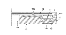
そして、地板10における駆動リング30側の面には、複数(図示例によれば2つ)のコイル11が固定され、その裏面側には、コイル11と同数の磁性部材12が固定される。
コイル11は、中空部を有する略矩形状に巻回された導線である。図示例においては位置決めするため、前記中空部を、地板10面に形成された凸部10gと嵌合するようにして固定される。
図示例によれば、二つのコイル11は、開口部10aを挟むようにして両側に位置するとともに、羽根部材20の支持箇所(支持軸10d)及び規制部10fに干渉しないように設けられる(図2、4及び5参照)。
尚、コイル11の形状は径方向の辺と半径方向とを揃え、周方向の外側辺を内側辺より長くした、略扇状とすることが好ましい。
A plurality of (two in the illustrated example)
The
According to the illustrated example, the two
The
また、磁性部材12は、例えば鉄、ニッケル、酸化クロム・コバルト・フェライト等の磁性体からなる平板状の部材であり、地板10の裏面側に形成された凹部10h(図3参照)において位置決めされる。
この磁性部材12は、コイル11の非通電時に、駆動リング30の永久磁石31を吸引して、駆動リング30に係合する羽根部材20を全閉状態に保持するように、その位置が設定される。図示例についてより具体的に説明すれば、この磁性部材12は、コイル11における、駆動リング30の閉鎖回転方向側(図6によれば右端側)の導線部分11aに対向するように設けられる(図2,4及び5参照)。
The
The position of the
また、駆動リング30は、合成樹脂材料により形成された略円環状の平板であり、地板10の環状軸10bに嵌まり合う軸孔30bを有する。この駆動リング30の外周部には、遠心方向へ突出する複数(図示例によれば2つ)の突出部30aを有する。また、駆動リング30における反地板側の面には、羽根部材20に係合するための駆動突起30cが複数設けられる。
The
突出部30aには、貫通状の嵌合孔30a1が設けられ、該嵌合孔30a1に永久磁石31が嵌合される。この突出部30a及び永久磁石31は、コイル11と同数設けられ、それぞれが、コイル11と対向するように配置される。
The
駆動ピン30cは、駆動リング30の周方向において等間隔に位置するように複数(図示例によれば5つ)設けられる。各駆動ピン30cは、円柱軸状の突起であり、後述する羽根部材20に遊挿される。
A plurality of drive pins 30 c (five in the illustrated example) are provided so as to be positioned at equal intervals in the circumferential direction of the
永久磁石31は、二つの永久磁石を組み合わせることで、図6に示すように、表面側と裏面側とで極性が逆になり、且つ駆動方向の一方側と他方側で極性が逆になるように構成される。
この永久磁石31の磁力は、羽根部材20の全開状態(図5参照)においてコイル11を非通電にした場合に、該永久磁石31と磁性部材12との間に生じる磁気吸引力によって、駆動リング30が回動して羽根部材20が全閉するように、適宜に設定されている。
As shown in FIG. 6, by combining two permanent magnets, the
The magnetic force of the
また、羽根部材20は、一端側に地板10の支持軸10dに環装される円形状の軸孔20aを有するとともに、その他端側に、開口部10aに臨んで該開口部10aの開口面積を変化させる遮光部20bを有する薄板状の部材である。
この羽根部材20における軸孔20aと遮光部20bの間には、駆動リング30の駆動ピン30cに係合する長孔状の駆動孔20cが設けられる。この駆動孔20cは、各羽根部材20が、駆動ピン30cの円弧状の運動に追従してスムーズに回動するように、駆動ピン30cの運動方向と交差する方向へ長く形成されている。
Further, the
Between the
さらに、羽根部材20における閉鎖回転方向側には、当該羽根部材20が閉鎖方向へ回動した際に地板10の規制部10fに当接して、羽根部材20の閉鎖方向の回転量を規制する規制突部20dが設けられる。
なお、複数(図示例によれば5つ)の羽根部材20のうち、前記規制突部20dに当接する羽根部材20は一部(図示例によれば3つ)のみである。他の羽根部材20については、駆動リング30を介して前記一部の羽根部材20に連動することで、閉鎖方向の回転量が規制されることになる。
Further, on the closing rotation direction side of the
Of the plurality (five in the illustrated example) of the
また、カバー部40は、地板10との間に駆動リング30及び羽根部材20を挟むようにして、地板10に止着される円盤状の部材である。
このカバー部40には、その中心部で開口部10aへ連通する貫通孔40aや、各羽根部材20を貫通した支持軸10dの先端側を支持する回転軸支持孔40b、羽根部材20に遊挿された駆動ピン30cを円弧状に往復運動可能に支持する駆動突起支持孔40c等が設けられる。
The
The
また、このカバー部40には、貫通状のセンサ嵌合孔40dが設けられ、このセンサ嵌合孔40dには、駆動リング30及び永久磁石31の回転方向の位置を検出する回転位置センサ41が嵌合され固定される。
回転位置センサ41は、ホール効果を利用して永久磁石31の磁界を検出する所謂ホールセンサである。
この回転位置センサ41は、当該カメラ用羽根駆動装置1がカメラ等に装着された状態では、図示しない制御回路に電気的に接続され、該制御回路に対し、永久磁石31の磁界の強さに応じた電気信号を送信する。
Further, the
The
The
次に、上記構成のカメラ用羽根駆動装置1について、その特徴的な作用効果を詳細に説明する。
先ず、コイル11への通電が行われていない非通電の状態を初期状態とする。この状態では、永久磁石31がその磁力によって地板10の磁性部材12方向へ吸引されるため(図6(a)参照)、駆動リング30が一方向(図示例によれば反時計方向)へ回動する。そして、回動する駆動リング30の駆動ピン30cによって、複数の羽根部材20が、それぞれ閉鎖方向(図示例によれば時計方向)へ回動する。したがって、これら複数の羽根部材20の遮光部20bによって開口部10aが全閉される(図2参照)。
この全閉状態は、複数の羽根部材20のうちの一部(図示例によれば3つ)が規制部10fに当接することにより、安定した静止状態に保持される。
この際、複数の羽根部材20のうち、規制部10fに当接しない羽根部材20(図示例によれば2つの羽根部材20)は、回動を停止した駆動リング30との係合によって静止状態に保持される。
Next, the characteristic operation and effects of the camera
First, a non-energized state where the
This fully closed state is maintained in a stable stationary state by a part (three in the illustrated example) of the plurality of
At this time, among the plurality of
また、コイル11への通電が行われた際には、コイル11の周囲に発生する磁界の作用によって、駆動リング30及び永久磁石31が他方向(図示例によれば時計方向)へ回動する。そして、回動する駆動リング30の駆動ピン30cによって、複数の羽根部材20が、それぞれ開放方向(図示例によれば反時計方向)へ回動する。したがって、複数の羽根部材20によって閉鎖されていた開口部10aが開放される。
この際、回転位置センサ41のフィードバック信号に応じてコイル11へ通電される電力や電流の向きを適宜に制御すれば、図4に示すように、開口部10aを任意の開放量(開口面積)とした状態で、羽根部材20及び駆動リング30を停止することができる。
When the
At this time, if the direction of the power and the current supplied to the
また、コイル11への通電により、図5に示すように、複数の羽根部材20を全開した場合には、駆動リング30における一方の突出部30aが、地板10の規制部10eに当接することで、その全開状態が安定した静止状態に保持される。
Further, as shown in FIG. 5, when the plurality of
また、複数の羽根部材20を再度閉鎖動作するには、コイル11へ逆電流を通電する。もしくは、コイル11を通電を断つことで非通電状態にしてもよい。
すなわち、コイル11に対し、開放動作時とは正負が逆の電流を通電すれば、コイル11の周囲に発生する磁界の作用により、駆動リング30及び永久磁石31が上記一方向(図示例によれば反時計方向)へ回動するため、複数の羽根部材20をそれぞれ閉鎖方向(図示例によれば時計方向)へ回動させることができる。
また、コイル11を非通電状態にした場合にも、永久磁石31と磁性部材12との間の磁気吸引力によって、駆動リング30及び永久磁石31が上記一方向(図示例によれば反時計方向)へ回動するため、複数の羽根部材20をそれぞれ閉鎖方向(図示例によれば時計方向)へ回動させることができる。
前記閉鎖動作を逆電流の通電により行うか、コイル11への通電を断つ非通電によって行うかは、当該カメラ用羽根駆動装置1の用途等に応じて選択が可能であり、例えば、複数の羽根部材20を敏速に閉鎖動作する必要がある場合等には、前者のように逆電流により閉鎖動作を行うことが好ましい。
In order to close the plurality of
That is, if a current having a polarity opposite to that during the opening operation is applied to the
Even when the
Whether the closing operation is performed by applying a reverse current or by de-energizing the
よって、本実施の形態のカメラ用羽根駆動装置1によれば、小型で簡素な構造の永久磁石31、コイル11及び磁性部材12を用いて、複数の羽根部材20を開閉動作させることができる上、これら羽根部材20を、非通電時には全閉位置に保持することができ、ひいては、当該カメラ用羽根駆動装置1を適用したデジタルカメラやデジタルビデオカメラ等において、非通電時に羽根部材20を全閉することでCCDやCMOS等を保護することができる。
Therefore, according to the camera
なお、上記実施の形態によれば、非通電時に羽根部材20を全閉状態に保持する構成としたが、他例としては、非通電時に羽根部材20を全開状態に保持する構成としてもよい。この場合には、磁性部材12を、コイル11における、駆動リング30の開放回転方向寄り(図6によれば左寄り)に配置すればよい。
さらに、他例としては、非通電時に羽根部材20を中途開放状態に保持する構成とすることも可能であり、この場合には、磁性部材12を、コイル11の中心部や該中心部の近傍等、羽根部材20が所望の開放量となる位置に設ければよい。
In addition, according to the said embodiment, although it was set as the structure which hold | maintains the
Furthermore, as another example, the
また、上記実施の形態によれば、永久磁石31、コイル11及び磁性部材12を、駆動リング30の外周に沿って2組設けたが、他例としては、1組としたり、3組以上とすることも可能である。
特に、比較的小型な構成によって高トルクを得られるようにするためには、永久磁石31、コイル11及び磁性部材12を2以上設けることが好ましく、この場合、駆動リング30の回転バランスを良好にする観点から、複数組の永久磁石31、コイル11及び磁性部材12のうち、少なくとも一組と他の一組とは、開口部10aを挟む位置であって且つ羽根部材20の支持箇所(支持軸10d)に干渉しない位置に設けるのが好ましい。
Moreover, according to the said embodiment, although 2 sets of the
In particular, in order to obtain a high torque with a relatively small configuration, it is preferable to provide two or more
また、上記実施の形態によれば、磁性部材12を磁性体としたが、磁性部材12の他例としては、磁性体を含む合成樹脂材料やゴム材料等とすることも可能である。さらに、磁性部材12の他例としては、駆動リング30の永久磁石31を吸引するように極性を配置した他の永久磁石とすることも可能である。
Moreover, according to the said embodiment, although the
また、本発明に係るカメラ用羽根駆動装置は、上記実施の形態によれば、カメラ用絞り装置に適用した好ましい一例を示したが、他例としては、カメラ用シャッタ装置に適用することも可能である。 Further, the camera blade driving device according to the present invention has been described as a preferable example applied to the camera diaphragm device according to the above embodiment, but as another example, it can also be applied to a camera shutter device. It is.
1:カメラ用羽根駆動装置
10:地板
10a:開口部
10d:支持軸(羽根部材の支持箇所)
11:コイル
12:磁性部材
20:羽根部材
30:駆動リング
31:永久磁石
41:回転位置センサ
1: Camera blade drive device 10:
11: Coil 12: Magnetic member 20: Blade member 30: Drive ring 31: Permanent magnet 41: Rotation position sensor
Claims (5)
前記駆動リングに、永久磁石を設け、
前記地板の駆動リング側の面に、通電することにより電磁力を発生させるコイルを設けるとともに、同地板における前記駆動リング側の面とは反対側の面に、前記永久磁石を吸引する磁性部材を設け、該コイルの非通電時に前記永久磁石と前記磁性部材との間に生じる磁気力により前記駆動リングを所定位置に保持するようにしたことを特徴とするカメラ用羽根駆動装置。 A ground plate having an opening for an optical path, a blade member that is supported by the ground plate and operates to open and close the opening, and a drive ring that is provided to rotate with respect to the ground plate. In the camera blade drive device which operates the blade member in conjunction with the drive ring,
A permanent magnet is provided on the drive ring,
The surface of the drive ring side of the base plate, provided with a coil for generating an electromagnetic force by energizing, on the opposite side to the drive ring side surface in where she plate, magnetic member for attracting the permanent magnet the provided camera blade drive device is characterized in that so as to retain in position the drive ring by a magnetic force generated between the permanent magnets when not energized and the magnetic member of said coil.
Priority Applications (5)
| Application Number | Priority Date | Filing Date | Title |
|---|---|---|---|
| JP2010217727A JP5604246B2 (en) | 2010-09-28 | 2010-09-28 | Camera blade drive |
| US13/240,292 US8475064B2 (en) | 2010-09-28 | 2011-09-22 | Camera blade drive device |
| TW100134618A TW201214019A (en) | 2010-09-28 | 2011-09-26 | Camera blade drive device |
| KR1020110096936A KR20120032433A (en) | 2010-09-28 | 2011-09-26 | Camera blade driving device |
| CN201110291556.7A CN102419504B (en) | 2010-09-28 | 2011-09-26 | Blade driving device for use in cameras |
Applications Claiming Priority (1)
| Application Number | Priority Date | Filing Date | Title |
|---|---|---|---|
| JP2010217727A JP5604246B2 (en) | 2010-09-28 | 2010-09-28 | Camera blade drive |
Publications (2)
| Publication Number | Publication Date |
|---|---|
| JP2012073383A JP2012073383A (en) | 2012-04-12 |
| JP5604246B2 true JP5604246B2 (en) | 2014-10-08 |
Family
ID=45870768
Family Applications (1)
| Application Number | Title | Priority Date | Filing Date |
|---|---|---|---|
| JP2010217727A Expired - Fee Related JP5604246B2 (en) | 2010-09-28 | 2010-09-28 | Camera blade drive |
Country Status (5)
| Country | Link |
|---|---|
| US (1) | US8475064B2 (en) |
| JP (1) | JP5604246B2 (en) |
| KR (1) | KR20120032433A (en) |
| CN (1) | CN102419504B (en) |
| TW (1) | TW201214019A (en) |
Cited By (1)
| Publication number | Priority date | Publication date | Assignee | Title |
|---|---|---|---|---|
| US11169430B2 (en) | 2018-05-10 | 2021-11-09 | Samsung Electro-Mechanics Co., Ltd. | Stop module and camera module including the same |
Families Citing this family (36)
| Publication number | Priority date | Publication date | Assignee | Title |
|---|---|---|---|---|
| JP5658071B2 (en) * | 2011-03-31 | 2015-01-21 | 日本電産コパル株式会社 | Image blur correction device |
| KR101953307B1 (en) * | 2012-04-02 | 2019-02-28 | 삼성전자주식회사 | Shutter assembly and photographing apparatus with the same |
| JP5826703B2 (en) * | 2012-04-24 | 2015-12-02 | オリンパス株式会社 | Light control system |
| KR102034621B1 (en) * | 2012-07-13 | 2019-10-21 | 삼성전자 주식회사 | Driving System For Shutter and Camera Device including the same, and Driving Method thereof |
| CN104937485B (en) * | 2012-11-26 | 2017-12-01 | 统雷有限公司 | Bistable electro magnetic control shutter |
| CN104155828B (en) * | 2014-08-26 | 2017-04-05 | 中国科学院光电技术研究所 | A kind of follow-on rotating shutter mechanism |
| JP6624786B2 (en) * | 2015-01-20 | 2019-12-25 | キヤノン株式会社 | Aperture device, lens device having the same, and imaging device |
| KR20170122747A (en) | 2015-02-27 | 2017-11-06 | 니덱 코팔 코포레이션 | Wing drive |
| KR20170123615A (en) * | 2015-02-27 | 2017-11-08 | 니덱 코팔 코포레이션 | Wing drive |
| CN105991908B (en) * | 2015-03-16 | 2019-06-07 | 迈科威特株式会社 | Camara module optical filter conversion equipment and include the mobile device of the module |
| JP6783559B2 (en) | 2015-06-12 | 2020-11-11 | キヤノン電子株式会社 | Blade drive device and image pickup device |
| USD881973S1 (en) | 2015-07-24 | 2020-04-21 | Canon Denshi Kabushiki Kaisha | Interchangeable lens for camera |
| WO2018105401A1 (en) * | 2016-12-09 | 2018-06-14 | 株式会社nittoh | Diaphragm device, lens barrel, and imaging device or projection device |
| CN107065393A (en) * | 2017-02-16 | 2017-08-18 | 北京灵铱科技有限公司 | A kind of mechanical shutter constructions |
| CN108663871B (en) | 2017-03-31 | 2021-06-25 | 上海微电子装备(集团)股份有限公司 | Shutter device |
| KR102104453B1 (en) * | 2017-11-09 | 2020-05-29 | 삼성전기주식회사 | Camera module |
| JP6892121B2 (en) * | 2017-12-21 | 2021-06-18 | 株式会社nittoh | Aperture device, lens barrel and image pickup device or projection device |
| US10976476B2 (en) * | 2018-01-25 | 2021-04-13 | Tdk Taiwan Corp. | Optical member driving mechanism |
| KR102207281B1 (en) * | 2018-05-10 | 2021-01-25 | 삼성전기주식회사 | Iris module and camera module including the same |
| KR102158710B1 (en) * | 2018-06-08 | 2020-09-22 | 삼성전기주식회사 | Camera module |
| KR102194708B1 (en) | 2018-07-20 | 2020-12-23 | 삼성전기주식회사 | Aperture module and camera module including the same |
| KR102213980B1 (en) * | 2018-08-17 | 2021-02-09 | 삼성전기주식회사 | Iris module and camera module including the same |
| KR102139767B1 (en) | 2018-08-22 | 2020-07-31 | 삼성전기주식회사 | Aperture stop and camera module including the same |
| US11473616B2 (en) | 2018-10-22 | 2022-10-18 | Raytheon Company | Flexure device |
| US10771710B2 (en) * | 2018-10-22 | 2020-09-08 | Raytheon Company | Shutter assembly for managing light relative to a photosensitive device |
| CN112955800B (en) * | 2018-10-25 | 2023-03-10 | 富士胶片株式会社 | Lens barrel |
| KR102185053B1 (en) | 2019-01-29 | 2020-12-01 | 삼성전기주식회사 | Aperture module and camera module including the same |
| KR102297281B1 (en) | 2019-03-21 | 2021-09-02 | 삼성전기주식회사 | Aperture module and camera module including the same |
| KR102248522B1 (en) * | 2019-06-18 | 2021-05-06 | 삼성전기주식회사 | Aperture module and camera module including the same |
| JP2022536186A (en) * | 2019-06-26 | 2022-08-12 | エスゼット ディージェイアイ テクノロジー カンパニー リミテッド | motor, shutter device and camera |
| KR102248523B1 (en) | 2019-06-28 | 2021-05-06 | 삼성전기주식회사 | Aperture module |
| CN211878277U (en) * | 2019-09-12 | 2020-11-06 | 台湾东电化股份有限公司 | Optical element driving mechanism |
| WO2021237713A1 (en) * | 2020-05-29 | 2021-12-02 | 深圳市大疆创新科技有限公司 | Shutter and camera device |
| CN116157730A (en) * | 2020-09-11 | 2023-05-23 | 华为技术有限公司 | Iris diaphragm apparatus |
| US20220413359A1 (en) * | 2021-06-23 | 2022-12-29 | New Shicoh Motor Co., Ltd. | Blade driving device, camera device and electronic apparatus |
| CN116991017A (en) * | 2022-04-22 | 2023-11-03 | 大立光电股份有限公司 | Imaging lens, camera module and electronic device |
Family Cites Families (8)
| Publication number | Priority date | Publication date | Assignee | Title |
|---|---|---|---|---|
| DE2942636C2 (en) * | 1978-10-23 | 1984-12-13 | Canon K.K., Tokio/Tokyo | Electromagnetically operated central lock |
| JPS6280636A (en) | 1985-10-04 | 1987-04-14 | Canon Inc | Diaphragm mechanism |
| JP2000347240A (en) * | 1999-03-31 | 2000-12-15 | Seiko Precision Inc | Shutter for camera |
| JP2002315293A (en) * | 2001-04-11 | 2002-10-25 | Nidec Copal Corp | Actuator |
| JP2005037866A (en) * | 2003-06-24 | 2005-02-10 | Alps Electric Co Ltd | Small-sized shutter |
| US20050152691A1 (en) * | 2004-01-09 | 2005-07-14 | Alps Electric Co., Ltd. | Shutter apparatus |
| JP2006284641A (en) * | 2005-03-31 | 2006-10-19 | Nidec Copal Corp | Blade drive unit for camera |
| US7513702B2 (en) * | 2005-11-16 | 2009-04-07 | Va, Inc. | Non-contact shutter activation system and method |
-
2010
- 2010-09-28 JP JP2010217727A patent/JP5604246B2/en not_active Expired - Fee Related
-
2011
- 2011-09-22 US US13/240,292 patent/US8475064B2/en not_active Expired - Fee Related
- 2011-09-26 KR KR1020110096936A patent/KR20120032433A/en not_active Application Discontinuation
- 2011-09-26 TW TW100134618A patent/TW201214019A/en unknown
- 2011-09-26 CN CN201110291556.7A patent/CN102419504B/en active Active
Cited By (1)
| Publication number | Priority date | Publication date | Assignee | Title |
|---|---|---|---|---|
| US11169430B2 (en) | 2018-05-10 | 2021-11-09 | Samsung Electro-Mechanics Co., Ltd. | Stop module and camera module including the same |
Also Published As
| Publication number | Publication date |
|---|---|
| TW201214019A (en) | 2012-04-01 |
| US8475064B2 (en) | 2013-07-02 |
| US20120076486A1 (en) | 2012-03-29 |
| KR20120032433A (en) | 2012-04-05 |
| CN102419504A (en) | 2012-04-18 |
| CN102419504B (en) | 2016-08-03 |
| JP2012073383A (en) | 2012-04-12 |
Similar Documents
| Publication | Publication Date | Title |
|---|---|---|
| JP5604246B2 (en) | Camera blade drive | |
| JP4849516B2 (en) | Driving device and light amount adjusting device | |
| US20080137348A1 (en) | Magnetic actuator and light quantity adjusting device | |
| US7679231B2 (en) | Driving device and light amount controller | |
| JP2009278758A (en) | Power transmitter | |
| WO2021097788A1 (en) | Switched electric motor, shutter device and camera device | |
| JP2004258062A (en) | Shutter driving device used also as diaphragm | |
| JP2007086547A (en) | Light quantity adjusting device | |
| JP5065933B2 (en) | Electromagnetic actuator | |
| JP2016061985A (en) | Magnetic driving device and imaging apparatus | |
| JP4934365B2 (en) | Light amount adjusting device and optical apparatus | |
| JP2016182011A (en) | Electromagnetic actuator, blade driving device, and camera | |
| JP2575353B2 (en) | DC motor | |
| JP2007047281A (en) | Light quantity adjustment device | |
| JP2005241957A (en) | Shutter device | |
| JP2016144276A (en) | Electromagnetic actuator, wing driving device, and camera | |
| JP6320959B2 (en) | Tilt actuator | |
| JP5709548B2 (en) | Light amount adjustment unit and optical apparatus including the same | |
| JP2019095508A (en) | Actuator, blade driving device, imaging device, and electronic apparatus | |
| JP4628001B2 (en) | Light intensity adjustment device | |
| JP5021053B2 (en) | Camera blade drive | |
| JP2001352741A (en) | Actuator | |
| JP2008160894A (en) | Electromagnetic actuator | |
| CN115877632A (en) | Iris diaphragm, driving mechanism thereof and lens with iris diaphragm | |
| JP2016065951A (en) | Electromagnetic actuator, vane driver and camera having vane driver |
Legal Events
| Date | Code | Title | Description |
|---|---|---|---|
| A621 | Written request for application examination |
Free format text: JAPANESE INTERMEDIATE CODE: A621 Effective date: 20130711 |
|
| A977 | Report on retrieval |
Free format text: JAPANESE INTERMEDIATE CODE: A971007 Effective date: 20140324 |
|
| A131 | Notification of reasons for refusal |
Free format text: JAPANESE INTERMEDIATE CODE: A131 Effective date: 20140408 |
|
| A521 | Request for written amendment filed |
Free format text: JAPANESE INTERMEDIATE CODE: A523 Effective date: 20140604 |
|
| TRDD | Decision of grant or rejection written | ||
| A01 | Written decision to grant a patent or to grant a registration (utility model) |
Free format text: JAPANESE INTERMEDIATE CODE: A01 Effective date: 20140805 |
|
| A61 | First payment of annual fees (during grant procedure) |
Free format text: JAPANESE INTERMEDIATE CODE: A61 Effective date: 20140825 |
|
| R150 | Certificate of patent or registration of utility model |
Ref document number: 5604246 Country of ref document: JP Free format text: JAPANESE INTERMEDIATE CODE: R150 |
|
| R250 | Receipt of annual fees |
Free format text: JAPANESE INTERMEDIATE CODE: R250 |
|
| R250 | Receipt of annual fees |
Free format text: JAPANESE INTERMEDIATE CODE: R250 |
|
| R250 | Receipt of annual fees |
Free format text: JAPANESE INTERMEDIATE CODE: R250 |
|
| LAPS | Cancellation because of no payment of annual fees |