JP5598973B2 - Bone fixation device - Google Patents
Bone fixation device Download PDFInfo
- Publication number
- JP5598973B2 JP5598973B2 JP2010178580A JP2010178580A JP5598973B2 JP 5598973 B2 JP5598973 B2 JP 5598973B2 JP 2010178580 A JP2010178580 A JP 2010178580A JP 2010178580 A JP2010178580 A JP 2010178580A JP 5598973 B2 JP5598973 B2 JP 5598973B2
- Authority
- JP
- Japan
- Prior art keywords
- pressure element
- receiving
- head
- bone anchoring
- opening
- Prior art date
- Legal status (The legal status is an assumption and is not a legal conclusion. Google has not performed a legal analysis and makes no representation as to the accuracy of the status listed.)
- Active
Links
Images


Classifications
-
- A—HUMAN NECESSITIES
- A61—MEDICAL OR VETERINARY SCIENCE; HYGIENE
- A61B—DIAGNOSIS; SURGERY; IDENTIFICATION
- A61B17/00—Surgical instruments, devices or methods, e.g. tourniquets
- A61B17/56—Surgical instruments or methods for treatment of bones or joints; Devices specially adapted therefor
- A61B17/58—Surgical instruments or methods for treatment of bones or joints; Devices specially adapted therefor for osteosynthesis, e.g. bone plates, screws, setting implements or the like
- A61B17/68—Internal fixation devices, including fasteners and spinal fixators, even if a part thereof projects from the skin
- A61B17/70—Spinal positioners or stabilisers ; Bone stabilisers comprising fluid filler in an implant
- A61B17/7001—Screws or hooks combined with longitudinal elements which do not contact vertebrae
- A61B17/7035—Screws or hooks, wherein a rod-clamping part and a bone-anchoring part can pivot relative to each other
- A61B17/7037—Screws or hooks, wherein a rod-clamping part and a bone-anchoring part can pivot relative to each other wherein pivoting is blocked when the rod is clamped
-
- A—HUMAN NECESSITIES
- A61—MEDICAL OR VETERINARY SCIENCE; HYGIENE
- A61B—DIAGNOSIS; SURGERY; IDENTIFICATION
- A61B17/00—Surgical instruments, devices or methods, e.g. tourniquets
- A61B17/56—Surgical instruments or methods for treatment of bones or joints; Devices specially adapted therefor
- A61B17/58—Surgical instruments or methods for treatment of bones or joints; Devices specially adapted therefor for osteosynthesis, e.g. bone plates, screws, setting implements or the like
- A61B17/68—Internal fixation devices, including fasteners and spinal fixators, even if a part thereof projects from the skin
- A61B17/70—Spinal positioners or stabilisers ; Bone stabilisers comprising fluid filler in an implant
- A61B17/7001—Screws or hooks combined with longitudinal elements which do not contact vertebrae
- A61B17/7032—Screws or hooks with U-shaped head or back through which longitudinal rods pass
Description
本発明は、ロッドを受けこのロッドを骨固定要素に結合するための受け部に関する。この受け部は、ロッドを受けるための溝部と骨固定要素の頭部を収容するための収容空間とを有する受け部本体、および、この頭部を締付けるための圧力要素を含む。収容空間の下側には、圧力要素を挿入するためかつ上記頭部を挿入するための開口がある。 The present invention relates to a receiving part for receiving a rod and coupling the rod to a bone anchoring element. The receiving portion includes a receiving portion body having a groove portion for receiving the rod and a receiving space for receiving the head portion of the bone fixing element, and a pressure element for tightening the head portion. Below the receiving space is an opening for inserting the pressure element and for inserting the head.
多軸骨ねじのさまざまな設計が知られており、骨ねじの回転位置は、頭部を側部から締付けることによって固定される。 Various designs of polyaxial bone screws are known, and the rotational position of the bone screw is fixed by tightening the head from the side.
米国特許第5,672,176号には、円錐形の座部と、圧力を頭部に対して上および側方から加える円錐形の圧力要素とを有する受け部を備えた骨ねじが記載されている。 U.S. Pat. No. 5,672,176 describes a bone screw with a receptacle having a conical seat and a conical pressure element that applies pressure to the head from above and from the side. ing.
米国特許第5,669,911号には、ロッドインプラント装置とともに使用するための多軸の整形外科用装置が記載されている。この整形外科用装置は、湾曲した頭部を有するねじと、その周りに配置されたロックカラーと、線形テーパ形状のソケットを有する受け部材とを含み、このソケットの中にはねじとカラーが重ねて収容される。カラーは受け部材の上端から差込まれる。ねじの頭部は下端から挿入することができる。 US Pat. No. 5,669,911 describes a multi-axis orthopedic device for use with a rod implant device. The orthopedic device includes a screw having a curved head, a locking collar disposed therearound, and a receiving member having a linear tapered socket in which the screw and collar overlap. Is contained. The collar is inserted from the upper end of the receiving member. The head of the screw can be inserted from the lower end.
米国特許第6,063,090号は、長手方向の支持体を、椎弓根ねじに、長手方向の支持体を収容する溝部を有する収容ヘッドによって接続するのに使用される装置に関する。椎弓根ねじと収容ヘッドは、収容ヘッド内の円錐形の組立チャックを介し、椎弓根ねじ上の球状の頭部によって、接続される。この装置は、椎弓根ねじが骨に挿入された後に、椎弓根ねじを収容ヘッドの中に係合させることができる。 U.S. Pat. No. 6,063,090 relates to an apparatus used to connect a longitudinal support to a pedicle screw with a receiving head having a groove for receiving the longitudinal support. The pedicle screw and the receiving head are connected by a spherical head on the pedicle screw via a conical assembly chuck in the receiving head. The device can engage the pedicle screw into the receiving head after the pedicle screw is inserted into the bone.
本発明の目的は、ロッドを受けこのロッドを骨固定要素に結合するための改良された受け部、および、構成部品が少なく、厚みが小さく、手術中の操作性が改善された、このような受け部を有する骨固定装置を提供することである。 It is an object of the present invention to provide an improved receiving portion for receiving a rod and coupling the rod to a bone anchoring element, and such components having fewer components, a reduced thickness, and improved operability during surgery. It is to provide a bone anchoring device having a receiving part.
この目的は、請求項1に記載の受け部および請求項15に記載の骨固定装置によって達成される。さらなる発展形は従属請求項に記載されている。
This object is achieved by a receiving part according to
この受け部の利点は、圧力要素が薄型設計なので、圧力要素を受け部本体内に底部から差込むことができることである。受け部本体内の内部端は、圧力要素との接触部を形成して頭部の挿入位置を定める。したがって、圧力要素を挿入位置で保持するためのさらなる構成要素は不要である。 The advantage of this receiving part is that the pressure element can be inserted into the receiving part body from the bottom because the pressure element is thin. The inner end in the receiving part main body forms a contact part with the pressure element to determine the insertion position of the head. Thus, no further components are required for holding the pressure element in the insertion position.
この受け部は厚みが小さく剛性が最大である。なぜなら、圧力要素が薄型設計であるために受け部本体の壁の厚みを大きくできるからである。 This receiving part has a small thickness and a maximum rigidity. This is because the thickness of the wall of the receiving portion main body can be increased because the pressure element has a thin design.
本発明のさらなる特徴および利点は、添付の図面を用いた実施例に関する説明から明らかになるであろう。 Further features and advantages of the present invention will become apparent from the description of embodiments with reference to the accompanying drawings.
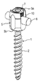
図1および図2に示されるように、第1の実施例に従う骨固定装置は、骨ねじの形態の骨固定要素1を含み、骨固定要素は、ねじが切られた軸2と、この実施例では球形セグメント形状の頭部である頭部3とを有する。頭部3は、ねじ込み工具と係合するための窪み4を有する。骨固定装置はさらに、ロッド6を受けてこのロッドを骨固定要素1に接続するための受け部本体5を含む。さらに、内ねじまたは止めねじの形態の閉鎖要素7が、ロッド6を受け部本体5内で固定するために設けられる。加えて、骨固定装置は、頭部を受け部本体5内でロックするための圧力要素8を含む。
As shown in FIGS. 1 and 2, the bone anchoring device according to the first embodiment comprises a
次に、受け部本体5について図1〜図3を参照しながら説明する。受け部本体5は、第1の端部5aと、第2の端部5bと、第1および第2の端部を通る対称軸Mとを含む。対称軸Mと同軸のボア9が、第1の端部5aから第2の端部5bまで延びている。ボア9は、受け部本体の中央領域内の中間部分91あたりまたはその近傍で、直径が最も小さい。第1の端部5aに隣接する第1の領域において、受け部本体5は、対称軸Mについて対称であるU字形の窪み10を有する。窪み10は、第2の端部5bの方向に底部を有し、側方の2つの自由脚11a、11bを与える。脚11a、11bの領域に、この実施例では止めねじである閉鎖要素7と協働する、雌ねじ12が設けられている。U字形の窪み10によって形成される溝部は、複数の固定装置を接続するロッド6を中で受けることができる大きさにされている。
Next, the
第2の端部5b近くの第2の領域で、受け部本体5は、第2の端部5bに向かって細くなる部分13を有する。この細くなる部分13は、圧力要素とともに、ねじ頭に対して座部を与える。細くなる部分13が、第2の端部5bから離れた場所にあることによって、ねじ軸2は一定の旋回角度範囲内で旋回できる。開口14が第2の端部5bに設けられ、開口の直径は、細くなる部分13の直径と同一またはそれよりも大きい。細くなる部分13とボア9の中間部91との間に、内径が細くなる部分13の直径よりも大きな部分が設けられ、この部分が、後で説明する圧力要素を拡張させることが可能な空間15を形成する。空間15は、細くなる部分13の反対側で、ボア9の中間部91の中へと延び、中間部91の直径はより小さいので、円形の肩部16を与える。
In the second region near the
ボア9の中間部91は、空間15の反対側で、円形の突起17によって制限され、これは以下でより詳細に説明するように止め具としても機能することができる。
The
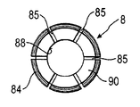
図1および図3〜図7からわかるように、圧力要素8は実質的に円筒形の第1の区域81を含み、第1の区域81は、圧力要素8がボア9内で移動できるよう外径がボア9の中間部91の内径より僅かに小さい。圧力要素はさらに第2の区域82を有し、第2の区域は中空の内部83を有し、この内部は、実質的に球状で、球状の頭部3を中で締付けるような大きさを有する。第1の区域81の外径は、図3からわかるように、頭部3の外径よりも小さく、第2の区域82の最大の外径は、円筒形区域81の外径よりも大きい。第2の区域82の自由端は、頭部3を差込むための開口84を与える。さらに、第2の区域82は、開口84の端部から第2の区域82を通って延びる複数のスリット85を含み、その中に幾分弾力のある脚90を定める。スリット85の数および寸法は、頭部3が挿入されるときに、第2の区域の壁が頭部3の上に嵌るのに十分な可撓性を第2の区域の壁に与えるような、数および寸法である。スリット85は、図面に示されるように、第1の円筒区域81の中まで延びて可撓性を高めることができる。第2の区域82の外壁表面は、球状の第1の部分86と、開口84に隣接し、開口84に向かってテーパ形状または湾曲形状をなしそうでなければ細くなる第2の部分87とを含む。この部分87は、頭部が受け部本体内でロックされたとき、受け部本体の細くなる部分13と協働する。
As can be seen from FIGS. 1 and 3 to 7, the
さらに、圧力要素は、工具によるねじ頭へのアクセスを与える同軸ボア88を含む。第1の区域81は、その自由端で、ロッド6を中で受けるための円筒形または円筒セグメント形の窪み89を有する。
In addition, the pressure element includes a
圧力要素8の寸法は、圧力要素8を受け部本体5の第2の端部5bの開口14を通して挿入するときに円筒形の第1の区域81を最初に挿入できるような寸法である。第2の区域82が開口14を通過しようとするとき、第2の区域82はそのまたはその脚90の可撓性によって圧縮され、これにより、圧力要素8を受け部本体5の中に完全に差込むことができる。
The dimensions of the
圧力要素8は、第1の区域81の上端部が、受け部本体5の環状の突起部によって設けられた止め具17に接触するまで、受け部本体5の中に押し込むことができる。圧力要素がこの位置にあるとき、可撓性のある第2の区域82は、ボア9の中間部91と受け部本体5の細くなる部分13との間の部分に位置する。空間15の中にはまだ、圧力要素の第2の区域82の外壁と、受け部本体5の内壁との間に、自由空間が残っているので、可撓性のある第2の区域82は、頭部3が挿入されるときにこの空間の中で拡張できる。
The
圧力要素の円筒形の窪み89の深さは、ロッド6の半径よりも小さいため、圧力要素8を押すロッド6を押す内ねじ7をねじ込むことによって、圧力要素は押下げられる。受け部本体5内で、圧力要素8は、その円筒形の窪み89が受け部本体5のU字形の窪みと整列するような方向に向けられる。
Since the depth of the
骨固定装置を作る構成要素の材料は、好ましくは、ステンレス鋼、チタンなどの生体適合性金属、ニッケルチタン合金、特にニチノールなどの生体適合性合金であるが、医療用途向けPEEKなどの生体適合性プラスチック材料を用いることができる。 The material of the component making the bone anchoring device is preferably a biocompatible metal such as stainless steel, titanium, a nickel titanium alloy, in particular a biocompatible alloy such as Nitinol, but biocompatible such as PEEK for medical applications. Plastic materials can be used.
使用時には、まず、圧力要素8が、下端の開口14を介して、止め具17に接触するまで受け部本体5の中に差込まれる。これは、受け部本体を圧力要素8とともに予め組立てるために、外科医がまたは前もって行なうことができる。その後、頭部3を下端の開口を通して差込み、止め具17に対して圧力要素8を上向きに押す。これが挿入位置であり、これによって、ねじ頭3を開口84を通して圧力要素8の中に挿入することで、中空の内部83または各脚90を、圧力要素8が頭部3の上に嵌められるまで、広げる。これは、ねじが切られた軸2を骨の中にねじ込む前に、または、受け部本体5とその内側の圧力要素を頭部3の上に載せることによってねじが切られた軸2を骨の中に挿入した後に、行なうことができる。頭部3は、挿入されたときには、可撓性の区域82が圧縮されていなければまだ圧力要素8の中で旋回できる。次に、複数の骨固定装置を、骨、たとえば隣り合う椎骨の根元にインプラントし、ロッド6をそれぞれに挿入する。次に受け部本体の角位置を調整してもよい。最後に、止めねじ7を締めることによって、ロッド6を圧力要素の上に対して押し下げる。圧力要素の第2の区域82の外壁の第2の部分87が、受け部本体の細くなる部分13と係合するまで、ロッド6は押し下げられる。この状態で、頭部が所望の角位置でロックされるように、頭部を圧力要素の内側で締付ける。
In use, first, the
図8a〜図8dは、受け部本体5の細くなる部分13と、細くなる部分13と係合する圧力要素の部分87の、さまざまな設計を示す。図8aは、これら2つの部分が、実質的に同一角度で線形的に先細りになる状態を示す。これは、圧力要素の第2の部分87と受け部本体5の細くなる部分13との間の圧力分布を実質的に均一にする。図8bおよび図8cは、これらの部分が異なる角度で先細りになる、2つの異なる設計を示す。図8bは主要な接触領域が下端部にある状態を示し、図8cは主要な接触領域が細くなる部分13の上端にある状態を示す。図8dは、圧力要素の先細りになる第2の部分87、および受け部本体の丸くされた部分13を示し、この湾曲は受け部本体5の中央の方向を向いている。このような構成を用いて、丸くされた部分に接触領域を位置付けることができる。
FIGS. 8 a to 8 d show various designs of the narrowing
図9aおよび図9bでは、受け部本体5の変形例の細くなる部分13′は、溝13cを間に挟んで隣り合う2つの湾曲部分13a、13bによって形成された球の2通りの半径を有する。この湾曲は中央軸Mの方向を向いている。これに対応して、変形圧力要素8′は、その下端に、湾曲部分13a、13bに対応し、頂点8cを間に挟む、2つの逆湾曲部分8a、8bを有し、外側の頂点8dは圧力要素の外側の曲がった端部にある。
9a and 9b, the narrowed portion 13 'of the modified example of the receiving
図9aに示されるように、圧力要素8′が下向きに移動すると、その最も下の端部は溝13cと係合する。この位置では頭部3は摩擦で保持されるが、それでもなお、頭部3が挿入位置に差込まれたときに頭部3を旋回させる力よりも大きな力が加えられると、頭部3は旋回する。これがロック前状態である。図9bに示されるように、圧力要素8′をさらに下向きに押すと、圧力要素8′の湾曲部分が細くなる部分13′の湾曲部分と係合し最終的に頭部3をロックする。
As shown in FIG. 9a, when the pressure element 8 'moves downward, its lowest end engages the
この骨固定装置にはさらなる変形が可能である。たとえば、圧力要素8は、上記の円筒形の窪み89に対応する、U字形でロッドを超えて延びる脚部を提供する窪みを有することができる。この場合は2部閉鎖要素を用いて頭部およびロッドを別々に固定することができる。圧力要素の回転を防止するための装置を設けることができる(図示せず)。このような装置は、たとえば締付けボアによって、または壁から圧力要素の窪み(図示せず)の中へと延びるピンによって、実現可能である。
Further deformations are possible for this bone anchoring device. For example, the
さらに、圧力要素が下端の開口を通して挿入されさらに内側に押された後に接触する接触部または止め具17は、たとえば円形の肩部16のような、受け部内の他の場所に設けてもよく、これは次に圧力要素の突起部と相互作用して圧力要素の接触部が生じる。
Furthermore, a contact or stop 17 that contacts after the pressure element is inserted through the opening at the lower end and pushed further inward may be provided elsewhere in the receptacle, such as a
1 骨固定要素、3 頭部、5 受け部本体、6 ロッド、7 閉鎖要素、8 圧力要素。 1 bone anchoring element, 3 head, 5 receiving body, 6 rod, 7 closing element, 8 pressure element.
Claims (13)
受け部本体(5)を含み、前記受け部本体は、
前記ロッド(6)を受けるための溝部と、
前記骨固定要素の前記頭部(3)を収容するための収容空間(9、15)とを有し、前記収容空間は前記頭部を差込むための開口(14)を有し、前記受け部は、第1の端部(5a)と、第2の端部(5b)と、前記第1の端部にあり前記ロッドのための前記溝部を形成する実質的にU字形の窪み(10)とを有し、前記開口(14)は前記第2の端部(5b)に設けられ、
前記受け部はさらに、
少なくとも一部が前記収容空間内に位置する圧力要素(8、8′)を含み、前記圧力要素は前記頭部を締付ける可撓性部分(82)を有し、
前記圧力要素は、前記開口(14)から挿入可能な大きさにされ、前記圧力要素は、前記開口(14)の直径よりも小さく、かつ、締付けられる前記頭部の最大の外径よりも小さい、第1の直径を有する実質的に円筒状の第1の区域(81)と、前記開口(14)の直径よりも大きな第2の直径を有する可撓性部分である第2の区域(82)とを有する、骨固定装置。 A bone anchoring element (1) comprising an axis (2) for anchoring in the bone and a head (3) having a maximum outer diameter; and a rod (6) for receiving said rod and said bone anchoring element (1) A bone anchoring device comprising a receiving part for coupling to the receiving part,
Including a receiving body (5), the receiving body being
A groove for receiving the rod (6);
And a receiving space (9, 15) for accommodating the head (3) of the bone anchoring element, the receiving space has an opening (14) for plugged the head, the receiving A first end (5a), a second end (5b), and a substantially U-shaped depression (10 at the first end forming the groove for the rod). And the opening (14) is provided at the second end (5b),
The receptacle further includes
Including a pressure element (8, 8 ') at least partially located in the receiving space, the pressure element having a flexible portion (82) for clamping the head;
The pressure element is sized to be inserted through the opening (14) , the pressure element being smaller than the diameter of the opening (14) and larger than the largest outer diameter of the head to be tightened. A first, substantially cylindrical, first zone (81) having a first diameter and a second zone (a flexible portion having a second diameter larger than the diameter of the opening (14)). 82) .
前記第1の端部(5a)に、閉鎖要素(7)と係合して前記溝部内で受けられた前記ロッド(6)を固定するためのねじ山(12)が設けられており、
前記開口(14)は前記第2の端部(5b)に設けられている、請求項1から9のいずれか1項に記載の骨固定装置。 The receptacle has a first end (5a), a second end (5b), and a bore (9) extending between the first end and the second end. ,
The first end (5a) is provided with a thread (12) for engaging the closure element (7) and fixing the rod (6) received in the groove,
The bone anchoring device according to any one of claims 1 to 9 , wherein the opening (14) is provided in the second end (5b).
前記圧力要素(8)は実質的に円筒形状の部分(81)を含み、前記円筒形状の部分の直径が、前記中空の円筒形状部分の直径に対応することにより、前記圧力要素が前記開口(14)を通して差込まれたとき、前記圧力要素が前記受け部本体の中で前記中空の円筒形状部分(9、91)の長手方向の軸(M)に沿って移動することができ、および/または
前記空間(15)の直径は、前記中空の円筒形状部分(9、91)よりも大きく、および/または
前記可撓性部分(82)の直径は、前記中空の円筒形状部分(9、91)よりも大きい、請求項1から10のいずれか1項に記載の骨固定装置。 The accommodating space (9, 15) includes a hollow cylindrical portion (9, 91) and a space (15) positioned between the opening (14) and the hollow cylindrical portion (9, 91). Including
The pressure element (8) comprises a substantially cylindrical part (81), the diameter of the cylindrical part corresponding to the diameter of the hollow cylindrical part, so that the pressure element is the opening ( 14) when inserted through 14), the pressure element can move along the longitudinal axis (M) of the hollow cylindrical part (9, 91) in the receptacle body, and / or Or the diameter of the space (15) is larger than the hollow cylindrical part (9, 91) and / or the diameter of the flexible part (82) is the hollow cylindrical part (9, 91) The bone anchoring device according to any one of claims 1 to 10 , which is larger than.
前記圧力要素(8′)は、その下端において、前記湾曲部分(13a、13b)に対応する2つの逆湾曲部分(8a、8b)を有し、内側の頂点(8c)が前記逆湾曲部分(8a、8b)の間に形成され、端部の頂点(8d)が前記逆湾曲部分の1つ(8a)の外側の端部を形成し、
前記端部の頂点(8d)は、前記圧力要素の第1のロック状態において、前記可撓性部分(82)の弾力によって前記溝(13c)の中に嵌められ、
前記内側の頂点(8c)は、第2のロック状態において、前記可撓性部分(82)の弾力によって前記溝(13c)の中に嵌められる、請求項6に記載の骨固定装置。 The narrowing portion (13) located next to the opening (14) has two curved portions (13a, 13b) adjacent to each other with a groove (13c) formed therebetween,
The pressure element (8 ') has, at its lower end, two reverse curved portions (8a, 8b) corresponding to the curved portions (13a, 13b), and an inner vertex (8c) is the reverse curved portion ( 8a, 8b), the apex (8d) of the end forming the outer end of one of the counter-curved portions (8a),
The apex (8d) of the end is fitted into the groove (13c) by the elasticity of the flexible part (82) in the first locked state of the pressure element,
The bone anchoring device according to claim 6 , wherein the inner apex (8c) is fitted into the groove (13c) by the elasticity of the flexible portion (82) in a second locked state.
Applications Claiming Priority (4)
| Application Number | Priority Date | Filing Date | Title |
|---|---|---|---|
| US23340609P | 2009-08-12 | 2009-08-12 | |
| EP09167751.8A EP2283786B1 (en) | 2009-08-12 | 2009-08-12 | A receiving part for receiving a rod for coupling the rod to a bone anchoring element |
| US61/233,406 | 2009-08-12 | ||
| EP09167751.8 | 2009-08-12 |
Publications (2)
| Publication Number | Publication Date |
|---|---|
| JP2011036666A JP2011036666A (en) | 2011-02-24 |
| JP5598973B2 true JP5598973B2 (en) | 2014-10-01 |
Family
ID=41402438
Family Applications (1)
| Application Number | Title | Priority Date | Filing Date |
|---|---|---|---|
| JP2010178580A Active JP5598973B2 (en) | 2009-08-12 | 2010-08-09 | Bone fixation device |
Country Status (7)
| Country | Link |
|---|---|
| US (5) | US9283000B2 (en) |
| EP (2) | EP2283786B1 (en) |
| JP (1) | JP5598973B2 (en) |
| KR (1) | KR101488952B1 (en) |
| CN (1) | CN101991458B (en) |
| ES (2) | ES2609079T3 (en) |
| TW (1) | TW201105289A (en) |
Families Citing this family (54)
| Publication number | Priority date | Publication date | Assignee | Title |
|---|---|---|---|---|
| US8366753B2 (en) | 2003-06-18 | 2013-02-05 | Jackson Roger P | Polyaxial bone screw assembly with fixed retaining structure |
| US7503924B2 (en) | 2004-04-08 | 2009-03-17 | Globus Medical, Inc. | Polyaxial screw |
| US8475495B2 (en) | 2004-04-08 | 2013-07-02 | Globus Medical | Polyaxial screw |
| US9393047B2 (en) | 2009-06-15 | 2016-07-19 | Roger P. Jackson | Polyaxial bone anchor with pop-on shank and friction fit retainer with low profile edge lock |
| US9980753B2 (en) * | 2009-06-15 | 2018-05-29 | Roger P Jackson | pivotal anchor with snap-in-place insert having rotation blocking extensions |
| US8556938B2 (en) | 2009-06-15 | 2013-10-15 | Roger P. Jackson | Polyaxial bone anchor with non-pivotable retainer and pop-on shank, some with friction fit |
| US8444681B2 (en) | 2009-06-15 | 2013-05-21 | Roger P. Jackson | Polyaxial bone anchor with pop-on shank, friction fit retainer and winged insert |
| US8100946B2 (en) | 2005-11-21 | 2012-01-24 | Synthes Usa, Llc | Polyaxial bone anchors with increased angulation |
| US9439681B2 (en) | 2007-07-20 | 2016-09-13 | DePuy Synthes Products, Inc. | Polyaxial bone fixation element |
| DE602008004916D1 (en) | 2007-07-20 | 2011-03-24 | Synthes Gmbh | Multi-axial bone fixation element |
| US8007522B2 (en) | 2008-02-04 | 2011-08-30 | Depuy Spine, Inc. | Methods for correction of spinal deformities |
| JP2012529969A (en) | 2008-08-01 | 2012-11-29 | ロジャー・ピー・ジャクソン | Longitudinal connecting member with tensioning cord with sleeve |
| US9282998B2 (en) | 2008-09-05 | 2016-03-15 | DePuy Synthes Products, Inc. | Bone fixation assembly |
| JP5815407B2 (en) | 2008-09-12 | 2015-11-17 | ジンテス ゲゼルシャフト ミット ベシュレンクテル ハフツング | Spinal stabilization and guided fixation system |
| DE09793113T8 (en) | 2008-09-29 | 2013-04-25 | Synthes Gmbh | POLYAXIAL BOTTOM CHARGE SCREW AND BAR ASSEMBLY |
| CA2742399A1 (en) | 2008-11-03 | 2010-06-03 | Dustin M. Harvey | Uni-planar bone fixation assembly |
| ES2548580T3 (en) | 2009-02-20 | 2015-10-19 | Biedermann Technologies Gmbh & Co. Kg | Receiving part for housing a rod for coupling to a bone anchoring element and bone anchoring device that includes such receiving part |
| WO2010120989A1 (en) | 2009-04-15 | 2010-10-21 | Synthes Usa, Llc | Revision connector for spinal constructs |
| US11464549B2 (en) | 2009-06-15 | 2022-10-11 | Roger P. Jackson | Pivotal bone anchor assembly with horizontal tool engagement grooves and insert with upright arms having flared outer portions |
| EP2757988A4 (en) | 2009-06-15 | 2015-08-19 | Jackson Roger P | Polyaxial bone anchor with pop-on shank and winged insert with friction fit compressive collet |
| WO2010148231A1 (en) | 2009-06-17 | 2010-12-23 | Synthes Usa, Llc | Revision connector for spinal constructs |
| JP2013545527A (en) | 2010-11-02 | 2013-12-26 | ロジャー・ピー・ジャクソン | Multi-axis bone anchor with pop-on shank and pivotable retainer |
| EP2460484A1 (en) * | 2010-12-01 | 2012-06-06 | FACET-LINK Inc. | Variable angle bone screw fixation assembly |
| US9186187B2 (en) | 2011-07-15 | 2015-11-17 | Globus Medical, Inc. | Orthopedic fixation devices and methods of installation thereof |
| US9358047B2 (en) | 2011-07-15 | 2016-06-07 | Globus Medical, Inc. | Orthopedic fixation devices and methods of installation thereof |
| US8888827B2 (en) | 2011-07-15 | 2014-11-18 | Globus Medical, Inc. | Orthopedic fixation devices and methods of installation thereof |
| US9198694B2 (en) | 2011-07-15 | 2015-12-01 | Globus Medical, Inc. | Orthopedic fixation devices and methods of installation thereof |
| US9993269B2 (en) * | 2011-07-15 | 2018-06-12 | Globus Medical, Inc. | Orthopedic fixation devices and methods of installation thereof |
| EP2606841B1 (en) * | 2011-12-23 | 2016-03-09 | Biedermann Technologies GmbH & Co. KG | Polyaxial bone anchoring device |
| ES2528969T3 (en) * | 2012-01-30 | 2015-02-13 | Biedermann Technologies Gmbh & Co. Kg | Bone anchoring device |
| KR101199458B1 (en) | 2012-02-17 | 2012-11-09 | 고려대학교 산학협력단 | Apparatus for fixation of spine |
| US9427260B2 (en) | 2012-03-01 | 2016-08-30 | Globus Medical, Inc. | Closed-head polyaxial and monaxial screws |
| EP2668918B1 (en) | 2012-05-29 | 2014-11-05 | Biedermann Technologies GmbH & Co. KG | Receiving part for receiving a rod for coupling the rod to a bone anchoring element and a bone anchoring device with such a receiving part |
| US9782204B2 (en) | 2012-09-28 | 2017-10-10 | Medos International Sarl | Bone anchor assemblies |
| EP2764840B1 (en) * | 2013-02-11 | 2017-05-03 | Biedermann Technologies GmbH & Co. KG | Coupling assembly for coupling a rod to a bone anchoring element and bone anchoring device with such a coupling assembly |
| US9724145B2 (en) | 2013-03-14 | 2017-08-08 | Medos International Sarl | Bone anchor assemblies with multiple component bottom loading bone anchors |
| US9775660B2 (en) | 2013-03-14 | 2017-10-03 | DePuy Synthes Products, Inc. | Bottom-loading bone anchor assemblies and methods |
| US9259247B2 (en) | 2013-03-14 | 2016-02-16 | Medos International Sarl | Locking compression members for use with bone anchor assemblies and methods |
| US10342582B2 (en) | 2013-03-14 | 2019-07-09 | DePuy Synthes Products, Inc. | Bone anchor assemblies and methods with improved locking |
| US20140277153A1 (en) | 2013-03-14 | 2014-09-18 | DePuy Synthes Products, LLC | Bone Anchor Assemblies and Methods With Improved Locking |
| TWI611796B (en) * | 2013-11-01 | 2018-01-21 | 捷鈦生醫股份有限公司 | Double-cushioned dental implant |
| US10543021B2 (en) | 2014-10-21 | 2020-01-28 | Roger P. Jackson | Pivotal bone anchor assembly having an open ring positioner for a retainer |
| DE102014222890B4 (en) * | 2014-11-10 | 2018-02-15 | Premiere Medical Gmbh | Pedicle screw and pedicle screw system |
| EP3031415B1 (en) * | 2014-12-10 | 2018-10-31 | Biedermann Technologies GmbH & Co. KG | Coupling assembly and polyaxial bone anchoring device comprising the same |
| US10874438B2 (en) | 2016-07-13 | 2020-12-29 | Medos International Sarl | Bone anchor assemblies and related instrumentation |
| US10568667B2 (en) * | 2016-07-13 | 2020-02-25 | Medos International Sàrl | Bone anchor assemblies and related instrumentation |
| EP3476340B1 (en) * | 2017-10-25 | 2021-06-02 | Biedermann Technologies GmbH & Co. KG | Polyaxial bone anchoring device |
| US11540863B2 (en) * | 2018-07-31 | 2023-01-03 | GetSet Surgical SA | Spinal surgery systems and methods |
| US11234738B2 (en) | 2018-11-16 | 2022-02-01 | Roger P. Jackson | Pivotal bone anchor assembly having a deployable collet insert with internal pressure ring |
| USD927687S1 (en) | 2019-06-07 | 2021-08-10 | GetSet Surgical SA | Surgical instrument handle |
| USD926978S1 (en) | 2019-06-07 | 2021-08-03 | GetSet Surgical SA | Surgical instrument handle |
| USD926312S1 (en) | 2019-06-07 | 2021-07-27 | GetSet Surgical SA | Surgical instrument handle |
| USD896384S1 (en) | 2019-06-07 | 2020-09-15 | GetSet Surgical SA | Spinal fusion cage |
| EP4111992B1 (en) * | 2021-07-01 | 2024-01-31 | Biedermann Technologies GmbH & Co. KG | Bone anchoring device |
Family Cites Families (46)
| Publication number | Priority date | Publication date | Assignee | Title |
|---|---|---|---|---|
| DE19509332C1 (en) | 1995-03-15 | 1996-08-14 | Harms Juergen | Anchoring element |
| US5669911A (en) | 1995-04-13 | 1997-09-23 | Fastenetix, L.L.C. | Polyaxial pedicle screw |
| US5879350A (en) * | 1996-09-24 | 1999-03-09 | Sdgi Holdings, Inc. | Multi-axial bone screw assembly |
| US5797911A (en) * | 1996-09-24 | 1998-08-25 | Sdgi Holdings, Inc. | Multi-axial bone screw assembly |
| ES2191775T3 (en) | 1996-12-12 | 2003-09-16 | Synthes Ag | DEVICE FOR CONNECTING A LONGITUDINAL SUPPORT WITH A PEDICULAR SCREW. |
| CN1142746C (en) * | 1996-12-12 | 2004-03-24 | 库尔斯恩蒂斯股份公司 | Device for connecting longitudinal support to pedicle screw |
| ATE310455T1 (en) * | 1997-01-22 | 2005-12-15 | Synthes Ag | DEVICE FOR CONNECTING A LONG SUPPORT TO A PEDICLE SCREW |
| DE19936286C2 (en) | 1999-08-02 | 2002-01-17 | Lutz Biedermann | bone screw |
| US6280442B1 (en) * | 1999-09-01 | 2001-08-28 | Sdgi Holdings, Inc. | Multi-axial bone screw assembly |
| US6626906B1 (en) * | 2000-10-23 | 2003-09-30 | Sdgi Holdings, Inc. | Multi-planar adjustable connector |
| US6368321B1 (en) | 2000-12-04 | 2002-04-09 | Roger P. Jackson | Lockable swivel head bone screw |
| KR100713095B1 (en) * | 2000-12-26 | 2007-05-02 | 파이오니아 가부시키가이샤 | Information recording medium, and information reproducing apparatus and its method |
| US20070016200A1 (en) * | 2003-04-09 | 2007-01-18 | Jackson Roger P | Dynamic stabilization medical implant assemblies and methods |
| US7322981B2 (en) | 2003-08-28 | 2008-01-29 | Jackson Roger P | Polyaxial bone screw with split retainer ring |
| KR101079022B1 (en) * | 2003-08-20 | 2011-11-01 | 워쏘우 오르쏘페딕 인코포레이티드 | Multi-axial orthopedic device and system e.g. for spinal surgery |
| FR2860138A1 (en) * | 2003-09-26 | 2005-04-01 | Stryker Spine | ASSEMBLY AND METHOD OF FIXING BONES |
| US8353933B2 (en) * | 2007-04-17 | 2013-01-15 | Gmedelaware 2 Llc | Facet joint replacement |
| DE102004010380A1 (en) * | 2004-03-03 | 2005-09-22 | Biedermann Motech Gmbh | Anchoring element and stabilizing device for the dynamic stabilization of vertebrae or bones with such an anchoring element |
| US8021398B2 (en) * | 2004-06-09 | 2011-09-20 | Life Spine, Inc. | Spinal fixation system |
| US7186255B2 (en) * | 2004-08-12 | 2007-03-06 | Atlas Spine, Inc. | Polyaxial screw |
| US20060058788A1 (en) * | 2004-08-27 | 2006-03-16 | Hammer Michael A | Multi-axial connection system |
| US7604655B2 (en) | 2004-10-25 | 2009-10-20 | X-Spine Systems, Inc. | Bone fixation system and method for using the same |
| US7445627B2 (en) * | 2005-01-31 | 2008-11-04 | Alpinespine, Llc | Polyaxial pedicle screw assembly |
| US10076361B2 (en) * | 2005-02-22 | 2018-09-18 | Roger P. Jackson | Polyaxial bone screw with spherical capture, compression and alignment and retention structures |
| US7476239B2 (en) * | 2005-05-10 | 2009-01-13 | Jackson Roger P | Polyaxial bone screw with compound articulation |
| AU2006241221A1 (en) * | 2005-04-25 | 2006-11-02 | Synthes Gmbh | Bone anchor with locking cap and method of spinal fixation |
| US7850715B2 (en) * | 2005-04-29 | 2010-12-14 | Warsaw Orthopedic Inc. | Orthopedic implant apparatus |
| US7988694B2 (en) * | 2005-09-29 | 2011-08-02 | K2M, Inc. | Spinal fixation system having locking and unlocking devices for use with a multi-planar, taper lock screw |
| US7722651B2 (en) | 2005-10-21 | 2010-05-25 | Depuy Spine, Inc. | Adjustable bone screw assembly |
| US7803174B2 (en) * | 2005-11-04 | 2010-09-28 | Warsaw Orthopedic, Inc. | Dorsal adjusting multi-rod connector |
| US8100946B2 (en) * | 2005-11-21 | 2012-01-24 | Synthes Usa, Llc | Polyaxial bone anchors with increased angulation |
| WO2007114834A1 (en) * | 2006-04-05 | 2007-10-11 | Dong Myung Jeon | Multi-axial, double locking bone screw assembly |
| US8361129B2 (en) | 2006-04-28 | 2013-01-29 | Depuy Spine, Inc. | Large diameter bone anchor assembly |
| BRPI0621728A2 (en) * | 2006-06-05 | 2012-10-16 | Traiber S L | vertebral fixation device and tool for mounting the same |
| US8016862B2 (en) * | 2006-09-27 | 2011-09-13 | Innovasis, Inc. | Spinal stabilizing system |
| US8167910B2 (en) * | 2006-10-16 | 2012-05-01 | Innovative Delta Technology Llc | Bone screw and associated assembly and methods of use thereof |
| WO2008118295A2 (en) | 2007-03-26 | 2008-10-02 | Laszlo Garamszegi | Bottom-loading pedicle screw assembly |
| US8197517B1 (en) * | 2007-05-08 | 2012-06-12 | Theken Spine, Llc | Frictional polyaxial screw assembly |
| US7942910B2 (en) * | 2007-05-16 | 2011-05-17 | Ortho Innovations, Llc | Polyaxial bone screw |
| DE602008004916D1 (en) * | 2007-07-20 | 2011-03-24 | Synthes Gmbh | Multi-axial bone fixation element |
| EP2185090A1 (en) * | 2007-07-26 | 2010-05-19 | Biotechni America Spine Group INC. | Spinal fixation assembly |
| WO2009029928A1 (en) * | 2007-08-31 | 2009-03-05 | University Of South Florida | Translational manipulation polyaxial screw head |
| US8287576B2 (en) * | 2007-10-23 | 2012-10-16 | K2M, Inc. | Mono-axial, taper lock bone screw |
| US8100909B2 (en) * | 2008-03-27 | 2012-01-24 | Life Spine, Inc. | Self-contained assembly for installation of orthopedic implant components onto an orthopedic implant |
| CA2742399A1 (en) * | 2008-11-03 | 2010-06-03 | Dustin M. Harvey | Uni-planar bone fixation assembly |
| ES2548580T3 (en) | 2009-02-20 | 2015-10-19 | Biedermann Technologies Gmbh & Co. Kg | Receiving part for housing a rod for coupling to a bone anchoring element and bone anchoring device that includes such receiving part |
-
2009
- 2009-08-12 EP EP09167751.8A patent/EP2283786B1/en active Active
- 2009-08-12 ES ES13158167.0T patent/ES2609079T3/en active Active
- 2009-08-12 EP EP13158167.0A patent/EP2609883B1/en active Active
- 2009-08-12 ES ES09167751.8T patent/ES2545206T3/en active Active
-
2010
- 2010-08-09 CN CN201010250983.6A patent/CN101991458B/en active Active
- 2010-08-09 TW TW099126408A patent/TW201105289A/en unknown
- 2010-08-09 JP JP2010178580A patent/JP5598973B2/en active Active
- 2010-08-09 KR KR20100076395A patent/KR101488952B1/en not_active IP Right Cessation
- 2010-08-12 US US12/855,395 patent/US9283000B2/en active Active
-
2015
- 2015-10-08 US US14/878,809 patent/US9895172B2/en active Active
-
2018
- 2018-01-16 US US15/872,428 patent/US10426522B2/en active Active
-
2019
- 2019-08-12 US US16/538,163 patent/US11160582B2/en active Active
-
2021
- 2021-10-04 US US17/493,042 patent/US11931079B2/en active Active
Also Published As
| Publication number | Publication date |
|---|---|
| TW201105289A (en) | 2011-02-16 |
| US9283000B2 (en) | 2016-03-15 |
| KR101488952B1 (en) | 2015-02-11 |
| EP2283786A1 (en) | 2011-02-16 |
| EP2609883A1 (en) | 2013-07-03 |
| US9895172B2 (en) | 2018-02-20 |
| US11160582B2 (en) | 2021-11-02 |
| ES2545206T3 (en) | 2015-09-09 |
| US20110213424A1 (en) | 2011-09-01 |
| US10426522B2 (en) | 2019-10-01 |
| US20200038065A1 (en) | 2020-02-06 |
| KR20110016828A (en) | 2011-02-18 |
| US11931079B2 (en) | 2024-03-19 |
| EP2283786B1 (en) | 2015-06-17 |
| US20160135847A1 (en) | 2016-05-19 |
| EP2609883B1 (en) | 2016-11-02 |
| ES2609079T3 (en) | 2017-04-18 |
| JP2011036666A (en) | 2011-02-24 |
| US20180146988A1 (en) | 2018-05-31 |
| US20220096130A1 (en) | 2022-03-31 |
| CN101991458A (en) | 2011-03-30 |
| CN101991458B (en) | 2016-03-30 |
Similar Documents
| Publication | Publication Date | Title |
|---|---|---|
| JP5598973B2 (en) | Bone fixation device | |
| JP6080718B2 (en) | Polyaxial bone anchoring device | |
| EP2764840B1 (en) | Coupling assembly for coupling a rod to a bone anchoring element and bone anchoring device with such a coupling assembly | |
| JP5415722B2 (en) | Bone fixation device | |
| JP5624760B2 (en) | Receiving part for receiving the rod and connecting it to the bone anchoring element, and a bone anchoring device having such a receiving part | |
| KR101559859B1 (en) | Receiving Part for Receiving a Rod for Coupling the Rod to a Bone Anchoring Element and Bone Anchoring Device with such a Receiving Part | |
| JP5613401B2 (en) | Receiving part for receiving the rod and connecting it to the bone anchoring element, and a bone anchoring device having such a receiving part | |
| EP2682062B1 (en) | Polyaxial bone anchoring device | |
| JP5610763B2 (en) | Receiving part for receiving the rod and a bone anchoring device for connecting the rod to the bone anchoring element | |
| JP5587565B2 (en) | Bone fixing device having plug member and tool for fitting plug member to bone fixing device | |
| US8926671B2 (en) | Receiving part for receiving a rod for coupling the rod to a bone anchoring element and a bone anchoring device with such a receiving part | |
| US9173684B2 (en) | Receiving part for receiving a rod for coupling the rod to a bone anchoring element and bone anchoring device with such a receiving part | |
| JP2008049166A (en) | Bone anchoring device | |
| US20130123858A1 (en) | Multiaxial pedicle attachment device for vertebral osteosynthesis | |
| JP2013176606A (en) | Bone fixation device |
Legal Events
| Date | Code | Title | Description |
|---|---|---|---|
| A711 | Notification of change in applicant |
Free format text: JAPANESE INTERMEDIATE CODE: A711 Effective date: 20121219 |
|
| A621 | Written request for application examination |
Free format text: JAPANESE INTERMEDIATE CODE: A621 Effective date: 20130123 |
|
| A977 | Report on retrieval |
Free format text: JAPANESE INTERMEDIATE CODE: A971007 Effective date: 20131112 |
|
| A131 | Notification of reasons for refusal |
Free format text: JAPANESE INTERMEDIATE CODE: A131 Effective date: 20131203 |
|
| A601 | Written request for extension of time |
Free format text: JAPANESE INTERMEDIATE CODE: A601 Effective date: 20140226 |
|
| A602 | Written permission of extension of time |
Free format text: JAPANESE INTERMEDIATE CODE: A602 Effective date: 20140303 |
|
| A601 | Written request for extension of time |
Free format text: JAPANESE INTERMEDIATE CODE: A601 Effective date: 20140430 |
|
| A602 | Written permission of extension of time |
Free format text: JAPANESE INTERMEDIATE CODE: A602 Effective date: 20140507 |
|
| A521 | Request for written amendment filed |
Free format text: JAPANESE INTERMEDIATE CODE: A523 Effective date: 20140602 |
|
| TRDD | Decision of grant or rejection written | ||
| A01 | Written decision to grant a patent or to grant a registration (utility model) |
Free format text: JAPANESE INTERMEDIATE CODE: A01 Effective date: 20140715 |
|
| A61 | First payment of annual fees (during grant procedure) |
Free format text: JAPANESE INTERMEDIATE CODE: A61 Effective date: 20140807 |
|
| R150 | Certificate of patent or registration of utility model |
Ref document number: 5598973 Country of ref document: JP Free format text: JAPANESE INTERMEDIATE CODE: R150 |
|
| R250 | Receipt of annual fees |
Free format text: JAPANESE INTERMEDIATE CODE: R250 |
|
| R250 | Receipt of annual fees |
Free format text: JAPANESE INTERMEDIATE CODE: R250 |
|
| R250 | Receipt of annual fees |
Free format text: JAPANESE INTERMEDIATE CODE: R250 |
|
| R250 | Receipt of annual fees |
Free format text: JAPANESE INTERMEDIATE CODE: R250 |
|
| R250 | Receipt of annual fees |
Free format text: JAPANESE INTERMEDIATE CODE: R250 |
|
| R250 | Receipt of annual fees |
Free format text: JAPANESE INTERMEDIATE CODE: R250 |
|
| R250 | Receipt of annual fees |
Free format text: JAPANESE INTERMEDIATE CODE: R250 |