JP5590460B2 - Dew point measuring device and gas characteristic measuring device - Google Patents

Dew point measuring device and gas characteristic measuring device Download PDF

Info

Publication number
JP5590460B2
JP5590460B2 JP2010274154A JP2010274154A JP5590460B2 JP 5590460 B2 JP5590460 B2 JP 5590460B2 JP 2010274154 A JP2010274154 A JP 2010274154A JP 2010274154 A JP2010274154 A JP 2010274154A JP 5590460 B2 JP5590460 B2 JP 5590460B2
Authority
JP
Japan
Prior art keywords
dew point
temperature
phase change
change material
point measuring
Prior art date
Legal status (The legal status is an assumption and is not a legal conclusion. Google has not performed a legal analysis and makes no representation as to the accuracy of the status listed.)
Active
Application number
JP2010274154A
Other languages
Japanese (ja)
Other versions
JP2012122862A (en
Inventor
順二 間中
Current Assignee (The listed assignees may be inaccurate. Google has not performed a legal analysis and makes no representation or warranty as to the accuracy of the list.)
Ricoh Co Ltd
Original Assignee
Ricoh Co Ltd
Priority date (The priority date is an assumption and is not a legal conclusion. Google has not performed a legal analysis and makes no representation as to the accuracy of the date listed.)
Filing date
Publication date
Application filed by Ricoh Co Ltd filed Critical Ricoh Co Ltd
Priority to JP2010274154A priority Critical patent/JP5590460B2/en
Publication of JP2012122862A publication Critical patent/JP2012122862A/en
Application granted granted Critical
Publication of JP5590460B2 publication Critical patent/JP5590460B2/en
Active legal-status Critical Current
Anticipated expiration legal-status Critical

Links

Images

Description

本発明は、露点計測装置に関するものである。また、露点計測装置を備えた湿度センサ、分圧測定器などの気体特性測定装置に関するものである。   The present invention relates to a dew point measuring apparatus. The present invention also relates to a gas characteristic measuring device such as a humidity sensor and a partial pressure measuring device equipped with a dew point measuring device.

冷却手段により鏡面状の観測面を冷却していき、周囲の気体中の特定成分(例えば、水蒸気)が観測面に凝集(結露)したことを光学センサなどの凝集検知手段で検知し、この気体中の特定成分が液化し始める温度(露点)を測定する鏡面冷却式露点計測装置が知られている(例えば、特許文献1や2)。   The mirror-like observation surface is cooled by the cooling means, and a specific component (for example, water vapor) in the surrounding gas is condensed (condensed) on the observation surface by the aggregation detection means such as an optical sensor. A mirror-cooled dew point measuring device that measures the temperature (dew point) at which a specific component in the liquid begins to liquefy is known (for example, Patent Documents 1 and 2).

露点計測装置は、観測面の温度を測定する温度測定手段としての温度センサを有しており、正確な露点を計測するには温度センサの較正を行う必要がある。温度センサを較正する方法としては、特許文献3、4に記載のものが知られている。特許文献3に記載の温度センサ較正方法では、既知の相転移温度を持つ温度標準物質及び温度センサを加熱炉内に設置する。そして、加熱炉内の温度を変化させていくと、温度標準物質の融点に相当する温度付近で温度標準物質の吸熱反応が発生する。この温度標準物質の吸熱反応は温度センサのリニアな出力変化での変曲点として検出される。そして、この変曲点の出力が検出されたときの温度を融点温度である温度標準とし、その温度標準を基づいて演算した補正値で温度センサの温度値を較正する。   The dew point measuring apparatus has a temperature sensor as temperature measuring means for measuring the temperature of the observation surface, and it is necessary to calibrate the temperature sensor in order to measure an accurate dew point. As a method for calibrating a temperature sensor, those described in Patent Documents 3 and 4 are known. In the temperature sensor calibration method described in Patent Document 3, a temperature standard substance having a known phase transition temperature and a temperature sensor are installed in a heating furnace. When the temperature in the heating furnace is changed, an endothermic reaction of the temperature standard material occurs near the temperature corresponding to the melting point of the temperature standard material. This endothermic reaction of the temperature standard substance is detected as an inflection point in the linear output change of the temperature sensor. Then, the temperature when the output of the inflection point is detected is set as a temperature standard that is a melting point temperature, and the temperature value of the temperature sensor is calibrated with a correction value calculated based on the temperature standard.

また、特許文献4に記載の温度センサの較正方法は、高圧高温装置内を適温になるように加熱するヒータに標準物質を直列に接続し、高圧高温装置内の温度を検出しながらヒータへの投入電力を調整する。そして、ヒータによって高圧高温装置内を加熱していき標準物質の相転移が起きたことをヒータの電気抵抗又はヒータへの電圧・電流の変化で捕え、その時の温度を検出する。そして、その時のヒータへの投入電力を基準とし、温度センサの温度較正を行う。   In addition, in the temperature sensor calibration method described in Patent Document 4, a standard material is connected in series to a heater that heats the inside of the high-pressure and high-temperature device to an appropriate temperature, and the temperature of the high-pressure and high-temperature device is detected while detecting the temperature in the high-temperature and high-temperature device. Adjust the input power. Then, the inside of the high-pressure and high-temperature apparatus is heated by the heater, and the occurrence of the phase transition of the standard material is detected by the change in the electric resistance of the heater or the voltage / current to the heater, and the temperature at that time is detected. Then, temperature calibration of the temperature sensor is performed with reference to the input power to the heater at that time.

しかしながら、上記特許文献3によれば、温度較正工程では加熱炉内に温度標準物質を搬送して行われるため、較正精度は温度センサに対する温度標準物質の位置精度に依存する。このため、較正精度を上げるためには位置精度を上げなければならず、位置精度を上げる設備投資等によって素子自体のコスト増につながってしまう。また、上記特許文献3において、温度センサを備えた露点計測装置を製品に組み込んだ後に温度較正を行うときは特に製品から露点計測装置を取り外してユーザが上記温度較正を行うこととなり、この煩雑な温度較正自体がユーザの負担となっていた。また、上記特許文献4によれば、ヒータと相変化物質とが電気的に直列に接続されているので、相変化物質の相転移による電気伝導度の変化に加え、ヒータの電気伝導度の変化も生じる。このため、相変化物質の相転移温度が検出できその温度で較正できたとしても、ヒータの電気伝導度の変化に伴う影響で温度較正の精度が低下してしまうという課題があった。   However, according to Patent Document 3, the temperature calibration process is performed by transporting the temperature standard material into the heating furnace, and therefore the calibration accuracy depends on the position accuracy of the temperature standard material with respect to the temperature sensor. For this reason, in order to increase the calibration accuracy, the position accuracy must be increased, and the cost of the element itself is increased due to equipment investment or the like for increasing the position accuracy. Further, in Patent Document 3, when temperature calibration is performed after a dew point measurement device having a temperature sensor is incorporated into a product, the user performs the temperature calibration by removing the dew point measurement device from the product. The temperature calibration itself is a burden on the user. According to Patent Document 4, since the heater and the phase change material are electrically connected in series, the change in the electrical conductivity of the heater in addition to the change in the electrical conductivity due to the phase transition of the phase change material. Also occurs. For this reason, even if the phase transition temperature of the phase change material can be detected and calibrated at that temperature, there has been a problem that the accuracy of temperature calibration is lowered due to the influence accompanying the change in the electric conductivity of the heater.

また、いずれの特許文献でも、一定の温度に制御した恒温環境となっている温度標準を備える大規模な設備が必要となる。更に、高い精度が求められるような高精度な露点計測装置においては、高精度な温度センサが用いられ、細かい温度較正を行う必要となる。よって、汎用な温度センサの温度較正に比べて煩雑な工程を必要としていた。そのため、高精度な露点計測装置は温度標準が一定の安定した恒温環境槽内に搬送されて温度変化を細かくして温度較正を行うために長い時間を要することになり、生産効率が悪くなる。そして、露点計測装置のそれ以外の素子(観測面を冷却するための冷却部などの冷却手段や光学センサなどの凝集検知手段)が簡単な電送装置や光学装置で迅速に設定が完了するのに比べ、高精度な温度センサを用いると、大量生産の製造工程において大量に取り扱うのにボトルネックとなっていてコストを削減することができない。このため、温度較正に要するコストが付加され、温度較正に要した露点計測装置の価格は温度較正に要しない露点計測装置の本体の価格に比して数倍ないし数十倍になっている。特に精度の高いものを生産するためには精度の高い温度較正を行うため費用と、かなりの時間を要していた。   In any patent document, a large-scale facility having a temperature standard that is a constant temperature environment controlled to a constant temperature is required. Furthermore, in a high-accuracy dew point measuring device that requires high accuracy, a high-accuracy temperature sensor is used, and fine temperature calibration is required. Therefore, a complicated process is required as compared with temperature calibration of a general-purpose temperature sensor. For this reason, a highly accurate dew point measuring device is transported into a stable thermostatic chamber where the temperature standard is constant, and it takes a long time to finely adjust the temperature and perform temperature calibration, resulting in poor production efficiency. And other elements of the dew point measurement device (cooling means such as a cooling unit for cooling the observation surface and agglomeration detection means such as an optical sensor) can be set quickly with a simple electric transmission device or optical device. On the other hand, if a high-precision temperature sensor is used, it becomes a bottleneck to handle a large amount in a mass production process, and the cost cannot be reduced. For this reason, the cost required for temperature calibration is added, and the price of the dew point measuring device required for temperature calibration is several times to several tens of times the price of the main body of the dew point measuring device not required for temperature calibration. In particular, in order to produce a highly accurate product, it took a considerable amount of time and time to perform temperature calibration with high accuracy.

よって、露点計測装置の製造において温度較正工程自体を無くすことがコスト削減に最も有効である。また、高い精度を維持するためには、随時簡便に温度較正を実施することができる露点計測装置の提供が望まれている。   Therefore, it is most effective to reduce the cost to eliminate the temperature calibration process itself in the manufacture of the dew point measuring device. In order to maintain high accuracy, it is desired to provide a dew point measuring device that can easily perform temperature calibration as needed.

本発明は以上の問題点に鑑みなされたものであり、その目的は、露点計測装置の製造工程において、温度較正工程を必要とせず、コストを抑えることができ、かつ、高い精度を維持することのできる露点計測装置および気体特性測定装置を提供することである。   The present invention has been made in view of the above problems, and its purpose is to eliminate the need for a temperature calibration step in the manufacturing process of a dew point measurement device, to reduce costs, and to maintain high accuracy. It is to provide a dew point measuring apparatus and a gas characteristic measuring apparatus capable of performing the above.

上記目的を達成するために、請求項1の発明は、観測面を冷却する冷却手段と、上記観測面に周囲の気体中の特定成分が凝集したことを検出する凝集検出手段と、上記観測面の温度を測定する温度測定手段とを備え、上記凝集検出手段が、観測面に周囲の気体中の特定成分が凝集したことを検出したとき、上記温度測定手段により上記観測面の温度を測定することで、気体の露点を測定する露点計測装置において、既知の相転移温度を持つ少なくとも1つの相変化物質と、温度の変化に伴って上記相変化物質の相転移が起きたことを検出する相転移検出手段と、相転移が起きたことを相転移検出手段が検出したときの上記温度測定手段の検知結果を、既知の上記相転移温度とする温度較正を行う温度較正手段と、上記相変化物質を加熱する加熱手段とを備え、少なくとも、上記冷却手段、上記温度測定手段、上記相変化物質および上記加熱手段を同一の基板に設けたことを特徴とするものである。
また、請求項2の発明は、請求項1の露点計測装置において、上記相変化物質は、国際温度目盛ITS−90に定義されている物質であることを特徴する露点計測装置。
また、請求項3の発明は、請求項1または2の露点計測装置において、上記冷却手段は、ぺルチェ効果を有する熱電変換材料と一対の電極とで構成されていることを特徴とするものである。
また、請求項4の発明は、請求項3の露点計測装置において、上記基板は、ベース材上に積層された絶縁層が設けられており、上記絶縁層に上記ベース材と接していない非接触領域を設け、上記非接触領域に、上記冷却手段の観測面の真下に配置され、観測面を冷却する冷却電極と、上記温度測定手段と、上記相変化物質とを配置したことを特徴する露点計測装置。
また、請求項5の発明は、請求項3または4の露点計測装置において、上記温度測定手段を上記観測面に隣接配置したことを特徴とするものである。
また、請求項6の発明は、請求項5の露点計測装置において、上記温度測定手段は、リング状であって、上記温度測定手段、上記冷却手段の順に同心円状に配置したことを特徴とするものである。
また、請求項7の発明は、請求項乃至6いずれかの露点計測装置において、上記冷却手段、上記温度測定手段の周囲を絶縁材で覆ったことを特徴とするものである。
また、請求項8の発明は、請求項1乃至7いずれかの露点計測装置において、上記相変化物質を上記加熱手段に隣接配置したことを特徴とするものである。
また、請求項の発明は、請求項1乃至8いずれかの露点計測装置において、上記相変化物質と上記加熱手段とを積層させたことを特徴とするものである。
また、請求項10の発明は、請求項1乃至8いずれかの露点計測装置において、上記相変化物質と上記加熱手段とを並列に配置したことを特徴とするものである。
また、請求項11の発明は、請求項1乃至10いずれかの露点計測装置において、上記加熱手段は、リング状であって、上記相変化物質を、上記リング状加熱手段と同心円となるように配置したことを特徴とするものである。
また、請求項12の発明は、請求項11の露点計測装置において、上記相変化物質を、上記加熱手段の円周内に配置したことを特徴とするものである。
また、請求項13の発明は、請求項1乃至12いずれかの露点計測装置において、上記加熱手段に隣接する箇所に上記相変化物質を分散配置したことを特徴とするものである。
また、請求項14の発明は、請求項13の露点計測装置において、互いに異なる2種類以上の相変化物質を分散配置したことを特徴とするものである。
また、請求項15の発明は、請求項1乃至14いずれかの露点計測装置において、上記温度測定手段は、温度依存性を有する抵抗体であって、上記温度測定手段を、上記加熱手段として用いたことを特徴とするものである。
また、請求項16の発明は、請求項15の露点計測装置において、上記温度測定手段を発熱させるための一対の発熱用リード線と、温度を測定するための一対の測定用リード線とをそれぞれ上記温度測定手段に接続したことを特徴とするものである。
また、請求項17の発明は、請求項1乃至14いずれかの露点計測装置において、上記冷却手段は、ペルチェ効果を有する熱電変換材料と一対の電極とで構成された冷却手段を備え、上記電極のいずれか一方を、加熱手段として用いたことを特徴とするものである。
また、請求項18の発明は、請求項17の露点計測装置において、上記相変化物質を加熱するときは上記熱電変換材料に流す電流の向きを、上記観測面を冷却するときの上記熱電変換材料に流す電流の向きと異ならせたことを特徴とするものである。
また、請求項19の発明は、請求項1乃至18いずれかの露点計測装置において、上記加熱手段の加熱温度を、上記相転移物質の相転移温度付近にしたことを特徴とするものである。
また、請求項20の発明は、請求項1乃至19いずれかの露点計測装置において、上記凝集検出手段は、上記鏡面状の観測面に光を照射する発光手段と、上記観測面からの反射光あるいは透過光を受光する受光手段とを備え、上記受光手段に入射する光量に基づいて、上記観測面に周囲の気体中の凝集成分が凝集したことを検知することを特徴とするものである。
また、請求項21の発明は、請求項20の露点計測装置において、上記受光手段は、上記観測面からの透過光を受光するものであって、上記冷却手段と、上記温度測定手段と、上記相変化物質と、が集積された第1基板と対向するように、上記発光手段を備えた第2基板を配置し、上記第1基板の上記第2基板と対向する面と反対側の面と対向するように、上記受光手段を備えた第3基板を配置して、上記第1基板、上記第2基板、上記第3基板を重ね合わせて一体化したことを特徴とするものである。
また、請求項22の発明は、請求項20の露点計測装置において、上記冷却手段と、上記温度測定手段と、上記相変化物質とが集積された基板に、上記発光手段と上記受光手段を設けたことを特徴とするものである。
また、請求項23の発明は、請求項22の露点計測装置において、上記発光手段から出射された光が、上記観測面に対して平行に横切って、受光手段に入射するよう、上記発光手段および上記受光手段を、上記基板の観測面と同一の面に設けたことを特徴とするものである。
また、請求項24の発明は、請求項22の露点計測装置において、上記受光手段は上記観測面からの反射光を受光するものであって、上記発光手段から出射された光を反射して上記観測面に入射させ、観測面から反射した光を反射して上記受光手段に入射させるための空洞部を上記基板に設けたことを特徴とするものである。
また、請求項25の発明は、請求項22の露点計測装置において、上記受光手段は上記観測面からの反射光を受光するものであって、上記基板に対向配置し、上記発光手段から出射された光を反射して上記観測面に入射させ、観測面から反射した光を反射して上記受光手段に入射させるための反射部材を、設けたことを特徴とするものである。
また、請求項26の発明は、請求項24または25の露点計測装置において、上記光が反射する面を平面にしたことを特徴とするものである。
また、請求項27の発明は、請求項24または25の露点計測装置において、上記光が反射する反射面を、上記受光手段へ光が集光するように曲面にしたことを特徴とするものである。
また、請求項28の発明は、請求項24乃至27いずれかの露点計測装置において、上記受光手段と上記発光手段とを、基板の上記冷却手段、上記温度測定手段、上記相変化物質が集積された面と同一の面に設けたことを特徴とするものである。
また、請求項29の発明は、請求項28の露点計測装置において、中心から上記相変化物質、上記温度測定手段、上記冷却手段の順に同心円状に配置されており、上記発光手段は、上記同心円の中心に配置され、上記受光手段は、上記冷却手段より円周外側に、同心円状に複数配置されており、上記空洞部を、上記同心円の中心を中心とする環状形状としたことを特徴とするものである。
また、請求項30の発明は、請求項24の露点計測装置において、上記発光手段と上記受光手段とを、基板の上記冷却手段、上記の温度測定手段、上記相変化物質が集積された面と反対側の面に設けたことを特徴とするものである。
また、請求項31の発明は、請求項30の露点計測装置において、中心から上記相変化物質、上記温度測定手段、上記冷却手段の順に同心円状に配置されており、上記発光手段は、上記同心円の中心と対向する位置に配置され、上記受光手段は、上記冷却手段より円周外側の部分に対向するように、同心円状に複数配置されており、上記空洞部を、上記同心円の中心を中心とする環状形状としたことを特徴とするものである。
また、請求項32の発明は、請求項1乃至31いずれかの露点計測装置において、上記相転移検出手段は、上記温度測定手段が測定した温度変化に基づいて、相転移が起きたことを検出することを特徴とするものである。
また、請求項33の発明は、請求項1乃至31いずれかの露点計測装置において、上記相転移検出手段は、上記相変化物質に積層させた圧電体を有し、圧電効果に基づいて、相転移が起きたことを検出することを特徴とするものである。
また、請求項34の発明は、請求項33の露点計測装置において、上記相転移検出手段は、上記相変化物質の圧電体に対する応力変化に基づいて、相転移が起きたことを検出することを特徴とするものである。
また、請求項35の発明は、請求項33の露点計測装置において、上記圧電体を振動させて、上記相変化物質の固有振動数の変化を検知することで、相転移が起きたことを検出することを特徴とするものである。
また、請求項36の発明は、請求項1乃至31いずれかの露点計測装置において、上記相変化物質は、導電性であって、上記相転移検出手段は、上記相変化物質の電気特性の変化に基づいて、相転移が起きたことを検出することを特徴とするものである。
また、請求項37の発明は、請求項36の露点計測装置において、上記相変化物質に接続し、上記相変化物質の電気特性の変化を検出するための検出リード線を、相変化物質と同一の材料で構成したことを特徴とするものである。
また、請求項38の発明は、請求項1乃至31いずれかの露点計測装置において、上記相変化物質は、導電性であって、上記相転移検出手段は、上記相変化物質の通電状態に基づいて、相転移が起きたことを検出することを特徴とするものである。
また、請求項39の発明は、請求項38の露点計測装置において、上記相転移検出手段は、上記相変化物質によって通電状態に構成しておき、相変化物質が相変化すると、非通電となるよう構成したことを特徴とするものである。
また、請求項40の発明は、請求項38の露点計測装置において、上記相転移検出手段は、上記相変化物質を分離させて、非通電に構成しており、相変化物質が相変化すると、上記相変化物質が結合して通電となるよう構成したことを特徴とするものである。
また、請求項41の発明は、請求項1乃至31いずれかの露点計測装置において、上記相変化物質は、光透過性または光反射性であり、上記相転移検出手段は、上記相変化物質の光学特性の変化に基づいて、相転移が起きたことを検出することを特徴とするものである。
また、請求項42の発明は、請求項41の露点計側装置において、上記凝集検出手段は、上記観測面に光を照射する発光手段と、上記観測面からの反射光あるいは透過光を受光する受光手段とを備え、上記凝集検出手段を、上記相転移検出手段として用いたことを特徴とするものである。
また、請求項43の発明は、請求項42の露点計測装置において、上記観測面の下に相変化物質を設けたことを特徴とするものである。
また、請求項44の発明は、請求項32乃至37、41乃至43いずれかの露点計測装置において、上記相変化物質の周囲を絶縁材で覆ったことを特徴とするものである。
また、請求項45の発明は、請求項1乃至44いずれかの露点計測装置において、少なくとも上記冷却手段と、上記温度測定手段と、上記相変化物質とを備えた露点検出部を、複数設けたことを特徴とするものである。
また、請求項46の発明は、請求項45の露点計測装置において、各露点検出部の熱容量を同じに構成し、これら露点計測部の温度測定手段でブリッジ回路を構成したことを特徴とするものである。
また、請求項47の発明は、請求項1乃至46いずれかの露点計測装置において、少なくとも、上記温度測定手段からの信号を受信して、温度を演算する演算回路、および、上記温度較正手段を備えた回路部を、上記冷却手段、上記温度測定手段および相変化物質を備えた基板に設けたことを特徴とするものである。
また、請求項48の発明は、気体の温度と、気体の露点とに基づいて、気体の特性を測定する気体特性測定装置において、上記露点を測定する露点測定手段として、請求項1乃至47いずれかの露点計測装置を用いたことを特徴とするものである。
また、請求項49の発明は、請求項48の気体特性測定装置において、上記観測面の周囲の気体温度を上記温度測定手段で測定した後、露点を測定することを特徴とするものである。
また、請求項50の発明は、請求項48気体特性測定装置において、周囲の気体の温度を測定する気体温度測定手段を設けたことを特徴とするものである。
また、請求項51の発明は、請求項48乃至50いずれかの気体特性測定装置において、当該気体特性測定装置は、気体の特性として、気体中の凝集成分の割合、気体の密度、気体成分の分圧のうちいずれか一つを測定することを特徴とするものである。
In order to achieve the above object, the invention of claim 1 comprises a cooling means for cooling the observation surface, an agglomeration detection means for detecting that a specific component in the surrounding gas has aggregated on the observation surface, and the observation surface. Temperature measurement means for measuring the temperature of the observation surface, and when the aggregation detection means detects that a specific component in the surrounding gas has aggregated on the observation surface, the temperature measurement means measures the temperature of the observation surface. Thus, in a dew point measurement device for measuring the dew point of a gas, at least one phase change material having a known phase transition temperature, and a phase for detecting that the phase change of the phase change material has occurred with a change in temperature. Transition detection means, temperature calibration means for performing temperature calibration using the detection result of the temperature measurement means when the phase transition detection means detects that a phase transition has occurred as the known phase transition temperature, and the phase change Heating the substance And means, at least, it is characterized in that the cooling means, the temperature measuring means, provided with the phase change material and the heating means on the same substrate.
The invention of claim 2 is the dew point measurement apparatus according to claim 1, wherein the phase change substance is a substance defined in the international temperature scale ITS-90.
Further, the invention of claim 3, in dew point measuring apparatus according to claim 1 or 2, it said cooling means, characterized in that it is composed of a thermoelectric conversion material and a pair of electrodes having a Peltier effect is there.
According to a fourth aspect of the present invention, in the dew point measuring apparatus according to the third aspect, the substrate is provided with an insulating layer laminated on a base material, and the insulating layer is not in contact with the base material. A dew point is provided in which a cooling electrode that cools the observation surface, the temperature measurement means, and the phase change material are arranged in the non-contact region, and is disposed immediately below the observation surface of the cooling means. Measuring device.
According to a fifth aspect of the present invention, in the dew point measuring apparatus according to the third or fourth aspect, the temperature measuring means is disposed adjacent to the observation surface.
The invention according to claim 6 is the dew point measuring apparatus according to claim 5, wherein the temperature measuring means is ring-shaped and is arranged concentrically in the order of the temperature measuring means and the cooling means. Is.
The invention of claim 7, in any of the dew point measuring apparatus according to claim 1 to 6, characterized in that said cooling means around the said temperature measuring means is Tsu covered with an insulating material.
The invention of claim 8, in any of the dew point measuring apparatus Motomeko 1 to 7, the phase change material is characterized in that arranged adjacent to the heating means.
The invention of claim 9 is characterized in that, in the dew point measurement device according to any one of claims 1 to 8 , the phase change material and the heating means are laminated.
The invention of claim 10 is characterized in that, in the dew point measuring device according to any one of claims 1 to 8 , the phase change material and the heating means are arranged in parallel.
The eleventh aspect of the present invention is the dew point measuring apparatus according to any one of the first to tenth aspects, wherein the heating means is ring-shaped, and the phase change material is concentric with the ring-shaped heating means. It is characterized by the arrangement.
According to a twelfth aspect of the present invention, in the dew point measuring apparatus according to the eleventh aspect , the phase change material is disposed within the circumference of the heating means.
The invention of claim 13 is characterized in that, in the dew point measuring device according to any one of claims 1 to 12 , the phase change material is dispersedly arranged at a location adjacent to the heating means.
The invention of claim 14 is characterized in that in the dew point measuring apparatus of claim 13 , two or more different phase change substances are dispersedly arranged.
The invention of claim 15 is the dew point measuring device according to any one of claims 1 to 14, wherein the temperature measuring means is a temperature-dependent resistor, and the temperature measuring means is used as the heating means. It is characterized by the fact that
The invention of claim 16 is the dew point measuring device of claim 15 , wherein a pair of heating lead wires for heating the temperature measuring means and a pair of measuring lead wires for measuring the temperature are respectively provided. The temperature measuring means is connected.
The invention according to claim 17 is the dew point measuring device according to any one of claims 1 to 14, wherein the cooling means includes a cooling means including a thermoelectric conversion material having a Peltier effect and a pair of electrodes. Any one of the above is used as a heating means.
The invention according to claim 18 is the dew point measuring device according to claim 17 , wherein the phase change material is heated when the direction of the current flowing through the thermoelectric conversion material is determined, and the thermoelectric conversion material when the observation surface is cooled. It is characterized in that it is different from the direction of the current passed through.
The invention of claim 19 is characterized in that, in the dew point measuring device according to any one of claims 1 to 18 , the heating temperature of the heating means is in the vicinity of the phase transition temperature of the phase change material.
According to a twentieth aspect of the present invention, in the dew point measuring device according to any one of the first to nineteenth aspects, the agglomeration detecting means includes a light emitting means for irradiating light to the specular observation surface and reflected light from the observation surface. Alternatively, a light receiving means for receiving transmitted light is provided, and based on the amount of light incident on the light receiving means, it is detected that aggregated components in the surrounding gas are aggregated on the observation surface.
The invention according to claim 21 is the dew point measurement apparatus according to claim 20 , wherein the light receiving means receives transmitted light from the observation surface, and the cooling means, the temperature measuring means, A second substrate having the light emitting means is disposed so as to face the first substrate on which the phase change material is integrated, and a surface of the first substrate opposite to the surface facing the second substrate; A third substrate provided with the light receiving means is disposed so as to face each other, and the first substrate, the second substrate, and the third substrate are overlapped and integrated.
According to a twenty-second aspect of the present invention, in the dew point measuring apparatus according to the twentieth aspect , the light emitting means and the light receiving means are provided on a substrate on which the cooling means, the temperature measuring means, and the phase change material are integrated. It is characterized by that.
The invention according to claim 23 is the dew point measurement device according to claim 22 , wherein the light emitted from the light emitting means crosses the observation surface parallel to the observation surface and enters the light receiving means. The light receiving means is provided on the same surface as the observation surface of the substrate.
The invention according to claim 24 is the dew point measuring apparatus according to claim 22 , wherein the light receiving means receives reflected light from the observation surface, and reflects the light emitted from the light emitting means to reflect the light. The substrate is provided with a cavity for reflecting the light incident on the observation surface and reflected from the observation surface to enter the light receiving means.
According to a twenty-fifth aspect of the present invention, in the dew point measuring apparatus according to the twenty-second aspect, the light receiving means receives reflected light from the observation surface, and is disposed opposite to the substrate and emitted from the light emitting means. A reflecting member is provided for reflecting the reflected light to be incident on the observation surface and reflecting the light reflected from the observation surface to be incident on the light receiving means.
According to a twenty-sixth aspect of the present invention, in the dew point measuring device according to the twenty-fourth or twenty-fifth aspect, the surface on which the light is reflected is flat.
The invention according to claim 27 is the dew point measuring device according to claim 24 or 25 , wherein the reflecting surface on which the light is reflected is curved so that the light is condensed on the light receiving means. is there.
The invention of claim 28 is the dew point measuring device according to any one of claims 24 to 27, wherein the light receiving means and the light emitting means are integrated with the cooling means for the substrate, the temperature measuring means, and the phase change material. It is characterized in that it is provided on the same surface as the other surface.
Further, the invention of claim 29 is the dew point measurement device of claim 28 , wherein the phase change material, the temperature measuring means, and the cooling means are arranged concentrically in this order from the center, and the light emitting means is the concentric circles. A plurality of the light receiving means are arranged concentrically outside the circumference of the cooling means, and the hollow portion has an annular shape centered on the center of the concentric circles. To do.
The invention of claim 30 is the dew point measurement device of claim 24 , wherein the light emitting means and the light receiving means are arranged such that the cooling means of the substrate, the temperature measuring means, and the surface on which the phase change material is integrated. It is provided on the opposite surface.
The invention of claim 31 is the dew point measurement device of claim 30 , wherein the phase change material, the temperature measuring means, and the cooling means are arranged concentrically in this order from the center, and the light emitting means is the concentric circles. A plurality of the light receiving means are arranged concentrically so as to face the outer circumferential part of the cooling means, and the cavity is centered on the center of the concentric circles. It is characterized by having an annular shape.
The invention of claim 32, in any one of the dew point measuring apparatus according to claim 1 to 31, the phase transition detecting means, based on the temperature change of the upper Symbol temperature measuring means to measure, that the phase transition occurs It is characterized by detecting.
Further, the invention of claim 33 is the dew point measurement device according to any one of claims 1 to 31, wherein the phase transition detection means includes a piezoelectric body laminated on the phase change material, and based on the piezoelectric effect, It is characterized by detecting that metastasis has occurred.
Further, in the invention of claim 34 , in the dew point measuring apparatus of claim 33 , the phase transition detection means detects that a phase transition has occurred based on a stress change of the phase change material to the piezoelectric body. It is a feature.
The invention of claim 35 is the dew point measurement device of claim 33 , wherein the piezoelectric body is vibrated to detect a change in the natural frequency of the phase change material, thereby detecting that a phase transition has occurred. It is characterized by doing.
The invention of claim 36 is the dew point measuring apparatus according to any one of claims 1 to 31, wherein the phase change material is electrically conductive, and the phase transition detection means changes the electrical characteristics of the phase change material. Based on the above, it is detected that a phase transition has occurred.
Further, the invention of claim 37 is the dew point measurement device of claim 36 , wherein the detection lead wire connected to the phase change material for detecting a change in electrical characteristics of the phase change material is the same as the phase change material. It is characterized by comprising the following materials.
Further, the invention of claim 38 is the dew point measuring apparatus according to any one of claims 1 to 31, wherein the phase change material is conductive, and the phase transition detection means is based on an energized state of the phase change material. Thus, it is characterized by detecting that a phase transition has occurred.
Further, the invention of claim 39 is the dew point measuring device according to claim 38 , wherein the phase transition detection means is configured to be energized by the phase change material and is deenergized when the phase change material undergoes a phase change. It is characterized by having comprised as follows.
Further, the invention of claim 40 is the dew point measurement device according to claim 38 , wherein the phase transition detection means separates the phase change material and is configured to be non-energized, and when the phase change material changes phase, The phase change material is combined to be energized.
The invention of claim 41 is the dew point measuring device according to any one of claims 1 to 31, wherein the phase change material is light-transmitting or light-reflecting, and the phase transition detection means is configured to detect the phase change material. It is characterized by detecting that a phase transition has occurred based on a change in optical characteristics.
The invention of claim 42 is the dew point meter side device of claim 41 , wherein the aggregation detecting means receives light emitting means for irradiating the observation surface with light and reflected light or transmitted light from the observation surface. A light receiving means, and the aggregation detection means is used as the phase transition detection means.
The invention according to claim 43 is the dew point measuring apparatus according to claim 42 , wherein a phase change material is provided below the observation surface.
The invention of claim 44 is characterized in that, in the dew point measuring device according to any one of claims 32 to 37, 41 to 43 , the periphery of the phase change material is covered with an insulating material.
Further, the invention of claim 45 is the dew point measuring device according to any one of claims 1 to 44 , wherein a plurality of dew point detection units each including at least the cooling means, the temperature measuring means, and the phase change material are provided. It is characterized by this.
The invention of claim 46 is characterized in that, in the dew point measuring device of claim 45 , the heat capacities of the dew point detectors are configured to be the same, and a bridge circuit is configured by the temperature measuring means of these dew point measuring units. It is.
The invention of claim 47 is the dew point measuring device according to any one of claims 1 to 46 , wherein at least a signal from the temperature measuring means is received and a temperature is calculated, and the temperature calibration means. The provided circuit section is provided on a substrate provided with the cooling means, the temperature measuring means, and the phase change material.
The invention of claim 48 provides a gas characteristic measuring apparatus for measuring gas characteristics based on the gas temperature and the gas dew point, wherein the dew point measuring means for measuring the dew point is any one of claims 1 to 47. The dew point measuring device is used.
According to a 49th aspect of the present invention, in the gas characteristic measuring apparatus according to the 48th aspect, the dew point is measured after the gas temperature around the observation surface is measured by the temperature measuring means.
The invention of claim 50 is characterized in that, in the gas characteristic measuring device of claim 48 , a gas temperature measuring means for measuring the temperature of the surrounding gas is provided.
Further, the invention of claim 51 is the gas characteristic measuring device according to any one of claims 48 to 50 , wherein the gas characteristic measuring device includes, as a gas characteristic, a ratio of agglomerated components in the gas, a gas density, a gas component Any one of the partial pressures is measured.

本発明においては、露点計測装置に相変化物質を設け、露点計測装置自身で、相変化物質の相転移が起きたことを検知し、そのときの温度測定手段の検知結果を、既知の相転移温度とする温度較正を露点計測装置自身で行う。これにより、露点計測装置の製造工程において、露点計測装置を恒温環境槽内へ搬送して温度較正を行う温度較正工程が必要なくなり、コストを抑えることができる。
また、露点計測装置自身で温度較正を行うことができるので、従来のように、露点計測装置が取り付けられた機器から露点計測装置を取り外して、恒温環境槽内に露点計測装置を持ち込んで温度較正を行う場合に比べて、随時簡便に温度較正を実施することができる。これにより、温度較正が必要なときに、温度較正を行うことができるので、高い精度を維持することができる。
In the present invention, a phase change material is provided in the dew point measurement device, and the dew point measurement device itself detects that the phase change of the phase change material has occurred, and the detection result of the temperature measuring means at that time is used as a known phase transition. The temperature calibration to make the temperature is performed by the dew point measuring device itself. Thereby, in the manufacturing process of a dew point measuring apparatus, the temperature calibration process which conveys a dew point measuring apparatus in a constant temperature environment tank and performs temperature calibration becomes unnecessary, and can suppress cost.
In addition, since the temperature can be calibrated by the dew point measuring device itself, the temperature calibration is performed by removing the dew point measuring device from the device with the dew point measuring device attached and bringing the dew point measuring device into the thermostatic chamber as in the past. Compared with the case of performing the temperature calibration, the temperature calibration can be easily performed at any time. Thereby, since temperature calibration can be performed when temperature calibration is required, high accuracy can be maintained.

また、気体中の特定成分の露点を計測する露点計測手段を備え、気体の露点に基づいて、気体の特性を測定する気体特性測定装置において、露点測定手段として、本発明の露点計測装置を用いることで、高い精度の露点測定を維持することができ、結果的に高い精度で気体の特性を測定することができる。また、コストが抑えられた露点計測装置を用いることができるので、結果的に、気体特性測定装置のコストを抑えることができる。   In addition, a dew point measuring means for measuring the dew point of a specific component in the gas is provided, and the dew point measuring apparatus according to the present invention is used as the dew point measuring means in the gas characteristic measuring device for measuring the characteristics of the gas based on the dew point of the gas. As a result, it is possible to maintain the dew point measurement with high accuracy, and as a result, it is possible to measure the gas characteristics with high accuracy. Moreover, since the dew point measuring apparatus with which cost was suppressed can be used, the cost of a gas characteristic measuring apparatus can be suppressed as a result.

以上本発明によれば、露点計測装置の製造工程において、露点計測装置を恒温環境槽内へ搬送して温度較正を行う温度較正工程を必要とせず、コストを抑えることができる。   As mentioned above, according to this invention, in the manufacturing process of a dew point measuring apparatus, a temperature calibration process which conveys a dew point measuring apparatus in a thermostat environment tank and performs temperature calibration is not required, and cost can be held down.

本実施形態の湿度センサの概略構成を示す平面図。The top view which shows schematic structure of the humidity sensor of this embodiment. 同湿度センサの裏面図。The back view of the humidity sensor. 図2のA−A断面図。AA sectional drawing of FIG. 同湿度センサの制御ブロック図。The control block diagram of the humidity sensor. 時間推移における相変化物質の温度変化と、温度測定部の抵抗変化とを示す特性図。The characteristic view which shows the temperature change of the phase change material in a time transition, and the resistance change of a temperature measurement part. 相変化物質を加熱するときに温度測定部に流す電流に対する温度変化及び温度測定部の抵抗値変化を示す特性図。The characteristic view which shows the temperature change with respect to the electric current sent through a temperature measurement part, and the resistance value change of a temperature measurement part when heating a phase change substance. 異なる相転移温度の2つの相変化物質において時間推移に対する温度変化を示す特性図。The characteristic view which shows the temperature change with respect to time transition in two phase change substances of a different phase transition temperature. 同湿度センサにおける温度キャリブレーション、温度、露点検出と湿度出力の入出力信号のタイミングチャート。Timing chart of input / output signals of temperature calibration, temperature and dew point detection and humidity output in the same humidity sensor. 同湿度センサにおける温度キャリブレーション、温度、露点検出のフローチャート。The flowchart of the temperature calibration in the same humidity sensor, temperature, and dew point detection. 抵抗値−温度特性を示すグラフ。The graph which shows resistance-temperature characteristics. 変形例1の湿度センサの概略平面図。The schematic plan view of the humidity sensor of the modification 1. FIG. 変形例2の湿度センサの概略平面図。The schematic plan view of the humidity sensor of the modification 2. FIG. 同変形例2の湿度センサにおける温度キャリブレーション、温度、露点検出と湿度出力の入出力信号のタイミングチャート。The timing chart of the input / output signal of the temperature calibration in the humidity sensor of the modification 2, temperature, dew point detection, and humidity output. 変形例2の湿度センサにおける温度キャリブレーション、温度、露点検出のフローチャート。10 is a flowchart of temperature calibration, temperature, and dew point detection in the humidity sensor of Modification 2. 変形例3の湿度センサの概略平面図。The schematic plan view of the humidity sensor of the modification 3. FIG. 同変形例3の湿度センサにおける温度キャリブレーション、温度、露点検出と湿度出力の入出力信号のタイミングチャート。The timing chart of the input / output signal of temperature calibration in the humidity sensor of the modification 3, temperature, dew point detection, and humidity output. 同変形例3の湿度センサにおける温度キャリブレーション、温度、露点検出のフローチャート。The flowchart of the temperature calibration in the humidity sensor of the modification 3, temperature, and dew point detection. 変形例4の湿度センサにおける温度キャリブレーション、温度、露点検出と湿度出力の入出力信号のタイミングチャート。10 is a timing chart of input / output signals of temperature calibration, temperature and dew point detection, and humidity output in the humidity sensor of Modification 4; 同変形例4の湿度センサにおける温度キャリブレーション、温度、露点検出のフローチャート。10 is a flowchart of temperature calibration, temperature, and dew point detection in the humidity sensor of Modification 4; 変形例5の湿度センサの概略平面図。The schematic plan view of the humidity sensor of the modification 5. FIG. 同変形例5の湿度センサにおける温度キャリブレーション、温度、露点検出と湿度出力の入出力信号のタイミングチャート。The timing chart of the input / output signal of temperature calibration in the humidity sensor of the modification 5, temperature, dew point detection, and humidity output. 同変形例5の湿度センサにおける温度キャリブレーション、温度、露点検出のフローチャート。10 is a flowchart of temperature calibration, temperature, and dew point detection in the humidity sensor of the fifth modification. 変形例6の湿度センサの概略平面図。The schematic plan view of the humidity sensor of the modification 6. FIG. 同変形例6の湿度センサの概略裏面図。The schematic back view of the humidity sensor of the modification 6. 図24のB−B断面図。BB sectional drawing of FIG. 変形例7の温度センサの概略平面図。FIG. 10 is a schematic plan view of a temperature sensor according to Modification 7. 変形例8の温度センサの概略平面図。The schematic plan view of the temperature sensor of the modification 8. 変形例9の湿度センサの概略平面図。The schematic plan view of the humidity sensor of the modification 9. FIG. 変形例10湿度センサの一例を示す概略平面図。Modification 10 Schematic plan view showing an example of a humidity sensor. 同変形例10湿度センサの他の例を示す概略平面図。The schematic plan view which shows the other example of the modification 10 humidity sensor. 相変化したときの相変化物質の流動(粘性)変化を電気的に検知するメカニズムについて説明する図。The figure explaining the mechanism which electrically detects the flow (viscosity) change of a phase change substance when a phase changes. 相変化したときの相変化物質の流動(粘性)変化を電気的に検知するメカニズムの他の構成例について説明する図。The figure explaining the other structural example of the mechanism which electrically detects the flow (viscosity) change of the phase change substance at the time of a phase change. 相変化したときの相変化物質の流動(粘性)変化を電気的に検知するメカニズムのさらに他の構成例について説明する図。The figure explaining the further another structural example of the mechanism which electrically detects the flow (viscosity) change of the phase change substance at the time of a phase change. 変形例10の湿度センサにおける温度キャリブレーション、温度、露点検出と湿度出力の入出力信号のタイミングチャート。The timing chart of the input / output signal of temperature calibration in the humidity sensor of the modification 10, temperature, dew point detection, and humidity output. 同変形例10の湿度センサにおける温度キャリブレーション、温度、露点検出のフローチャート。The flowchart of the temperature calibration in the humidity sensor of the modification 10, temperature, and dew point detection. 同変形例10の湿度センサにおいて、冷却部の冷却電極で、相変化物質を加熱する場合の温度キャリブレーション、温度、露点検出と湿度出力の入出力信号のタイミングチャート。In the humidity sensor of the modification 10, the timing chart of the input / output signal of temperature calibration, temperature, dew point detection, and humidity output when the phase change material is heated by the cooling electrode of the cooling unit. 同変形例10の湿度センサにおいて、冷却部の冷却電極で、相変化物質を加熱する場合の温度キャリブレーション、温度、露点検出のフローチャート。The humidity sensor of the modification 10 WHEREIN: The flowchart of the temperature calibration in the case of heating a phase change substance with the cooling electrode of a cooling part, temperature, and a dew point detection. 変形例10−1の湿度センサ一例を示すの概略平面図。The schematic plan view which shows an example of the humidity sensor of the modification 10-1. 同変形例10−1の湿度センサの他の例を示す概略平面図。The schematic plan view which shows the other example of the humidity sensor of the modification 10-1. 同変形例10−1の湿度センサにおける温度キャリブレーション、温度、露点検出と湿度出力の入出力信号のタイミングチャート。The timing chart of the input / output signal of temperature calibration in the humidity sensor of the modification 10-1, temperature, dew point detection, and humidity output. 同変形例10−1の湿度センサにおいて、冷却部の冷却電極で、相変化物質を加熱する場合の温度キャリブレーション、温度、露点検出のフローチャート。The humidity sensor of the modification 10-1 WHEREIN: The temperature calibration in the case of heating a phase change substance with the cooling electrode of a cooling part, the flowchart of temperature and a dew point detection. 変形例10−2の湿度センサの概略平面図。The schematic plan view of the humidity sensor of modification 10-2. 同変形例10−2の湿度センサにおける温度キャリブレーション、温度、露点検出と湿度出力の入出力信号のタイミングチャート。The timing chart of the input / output signal of temperature calibration in the humidity sensor of the modification 10-2, temperature, dew point detection, and humidity output. 変形例11の湿度センサの制御ブロック図。The control block diagram of the humidity sensor of the modification 11. FIG. 同変形例11の湿度センサの一例を示す概略平面図。The schematic plan view which shows an example of the humidity sensor of the modification 11. FIG. 同変形例11の湿度センサの他の例を示す概略平面図。The schematic plan view which shows the other example of the humidity sensor of the modification 11. FIG. 変形例12の湿度センサの断面図。Sectional drawing of the humidity sensor of the modification 12. FIG. 変形例13の湿度センサの断面図。Sectional drawing of the humidity sensor of the modification 13. FIG. 同変形例13の湿度センサの制御ブロック図。The control block diagram of the humidity sensor of the modification 13. 変形例14の湿度センサの制御ブロック図。The control block diagram of the humidity sensor of the modification 14. フォトカプラで凝集検知と相変化検知とを行う変形例14の湿度センサの説明図。Explanatory drawing of the humidity sensor of the modification 14 which performs aggregation detection and phase change detection with a photocoupler. 同変形例14の湿度センサの温度キャリブレーション、温度、露点検出と湿度出力の入出力信号のタイミングチャート。The timing chart of the input / output signal of temperature calibration of the humidity sensor of the modification 14, temperature, dew point detection, and humidity output. 同変形例14の湿度センサにおいて、冷却部の冷却電極で、相変化物質を加熱する場合の温度キャリブレーション、温度、露点検出のフローチャート。The humidity sensor of the modification 14 WHEREIN: The temperature calibration in the case of heating a phase change substance with the cooling electrode of a cooling unit, a flowchart of temperature and dew point detection. 同変形例14湿度センサの一例を示す概略平面図。The schematic plan view which shows an example of the modification 14 humidity sensor. 同変形例14の湿度センサの他の例を示す概略断面図。The schematic sectional drawing which shows the other example of the humidity sensor of the modification 14. 同変形例14の湿度センサのさらに他の例を示す概略断面図。The schematic sectional drawing which shows the other example of the humidity sensor of the modification 14. 変形例15の湿度センサの概略構成図。The schematic block diagram of the humidity sensor of the modification 15. 同変形例16の湿度センサの第1例を示す概略構成図。The schematic block diagram which shows the 1st example of the humidity sensor of the modification 16. 同変形例16の湿度センサの第2例を示す概略平面図。The schematic plan view which shows the 2nd example of the humidity sensor of the modification 16. FIG. 同変形例16の湿度センサの第3例を示す概略平面図。The schematic plan view which shows the 3rd example of the humidity sensor of the modification 16. 同変形例16の湿度センサの第4例を示す概略平面図。The schematic plan view which shows the 4th example of the humidity sensor of the modification 16. 同変形例16の湿度センサの第5例を示す概略構成図。The schematic block diagram which shows the 5th example of the humidity sensor of the modification 16. 変形例17の湿度センサの第1例を示す概略断面図。FIG. 16 is a schematic cross-sectional view showing a first example of a humidity sensor according to Modification 17; 同変形例17の湿度センサの第1例における受光基板の概略平面図。The schematic plan view of the light-receiving board | substrate in the 1st example of the humidity sensor of the modification 17. 同変形例17の湿度センサの第1例における発光基板の概略平面図。The schematic plan view of the light emission board | substrate in the 1st example of the humidity sensor of the modification 17. FIG. 同変形例17の湿度センサの第2例の概略断面図。The schematic sectional drawing of the 2nd example of the humidity sensor of the modification 17. FIG. 同変形例17の湿度センサの第2例における発光基板の概略平面図。The schematic plan view of the light emission board | substrate in the 2nd example of the humidity sensor of the modification 17. FIG. 同変形例17の湿度センサの第3例の概略断面図。The schematic sectional drawing of the 3rd example of the humidity sensor of the modification 17. FIG. 同変形例17の湿度センサの第3例における発光基板の概略平面図。The schematic plan view of the light emission board | substrate in the 3rd example of the humidity sensor of the modification 17. FIG. 同変形例17の湿度センサの第3例における受光基板の概略平面図。The schematic plan view of the light-receiving board | substrate in the 3rd example of the humidity sensor of the modification 17. 同変形例17の湿度センサの第4例の概略断面図。The schematic sectional drawing of the 4th example of the humidity sensor of the modification 17. 同変形例17の湿度センサの第4例における発光基板の概略平面図。The schematic plan view of the light emission board | substrate in the 4th example of the humidity sensor of the modification 17. FIG. 変形例18の湿度センサの第1例の概略構成図。The schematic block diagram of the 1st example of the humidity sensor of the modification 18. FIG. 同変形例18の湿度センサをケースに設けた構成例を示す図。The figure which shows the structural example which provided the humidity sensor of the modification 18 in the case. 同変形例18の湿度センサの第2例の概略構成図。The schematic block diagram of the 2nd example of the humidity sensor of the modification 18. FIG. 基板のポリシリコン層に熱交換材料と温度測定部と加熱部とを配置した湿度センサの構成を示す断面図。Sectional drawing which shows the structure of the humidity sensor which has arrange | positioned the heat exchange material, the temperature measurement part, and the heating part to the polysilicon layer of a board | substrate. 変形例19の湿度センサの第1例の概略構成図。The schematic block diagram of the 1st example of the humidity sensor of the modification 19. FIG. 同変形例19の湿度センサの第2例の概略断面図。The schematic sectional drawing of the 2nd example of the humidity sensor of the modification 19. 変形例20の湿度センサの概略構成図。The schematic block diagram of the humidity sensor of the modification 20. FIG. 第1検知部の第1温度測定部5−1と第2検知部の第2温度測定部5−2の温度補償用の検出器としてのブリッジ回路を示す図。The figure which shows the bridge circuit as a detector for temperature compensation of the 1st temperature measurement part 5-1 of a 1st detection part, and the 2nd temperature measurement part 5-2 of a 2nd detection part. 周囲温度が変化しないときの第1の温度測定部の抵抗値変化と第2の温度測定部の抵抗値変化の特性を示す図。The figure which shows the resistance value change of the 1st temperature measurement part when ambient temperature does not change, and the characteristic of the resistance value change of a 2nd temperature measurement part. ブリッジ回路で出力される特性を示す図。The figure which shows the characteristic output by a bridge circuit. 変形例21の湿度センサの概略構成図。The schematic block diagram of the humidity sensor of the modification 21. FIG.

以下、本発明の露点検出装置を湿度センサに適用した一実施形態について説明する。
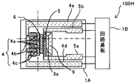
図1は、本実施形態の気体特性測定装置としての湿度センサ100の概略構成を示す平面図であり、図2は、湿度センサ100の裏面図であり、図3は、図2のA−A断面図である。
図1に示すように、本実施形態の湿度センサ100は、ベース材2と、ベース材2の両面に形成された電気絶縁層3a,3bとからなる基板1上に、雰囲気温度や露点を検出ための検出部たる検出領域1aと、電力供給を行うための回路や、湿度などを検出するための回路など有する回路部たる回路領域1bとを有している。
基板1の検出領域1aには、冷却手段としての冷却部4と、温度測定手段としての温度測定部5と、2種類の相変化物質6A,6Bとを設けている。温度測定部5は、温度依存性を持つ抵抗体であり、回路領域1でこの抵抗体の抵抗値を求めることにより、温度が検知される。また、この実施形態においては、この抵抗体からなる温度測定部5を発熱させて相変化物質6A,6Bを加熱する加熱手段としての機能を有している。温度測定部5は、リング状に形成されており、その両端にはリード線5a,5bが接続され、回路領域1bに接続されている。この温度測定部5の外周に温度測定部5と同心円状に冷却部4が形成されている。
Hereinafter, an embodiment in which the dew point detection device of the present invention is applied to a humidity sensor will be described.
FIG. 1 is a plan view showing a schematic configuration of a humidity sensor 100 as a gas characteristic measuring apparatus of the present embodiment, FIG. 2 is a back view of the humidity sensor 100, and FIG. It is sectional drawing.
As shown in FIG. 1, the humidity sensor 100 of the present embodiment detects an ambient temperature and a dew point on a substrate 1 composed of a base material 2 and electrical insulating layers 3 a and 3 b formed on both surfaces of the base material 2. And a circuit region 1b serving as a circuit unit having a circuit for supplying power and a circuit for detecting humidity and the like.
The detection region 1a of the substrate 1 is provided with a cooling unit 4 as a cooling unit, a temperature measuring unit 5 as a temperature measuring unit, and two types of phase change substances 6A and 6B. The temperature measuring unit 5 is a temperature-dependent resistor, and the temperature is detected by obtaining the resistance value of the resistor in the circuit region 1. Moreover, in this embodiment, it has a function as a heating means which heats the phase change materials 6A and 6B by causing the temperature measuring unit 5 made of this resistor to generate heat. The temperature measuring unit 5 is formed in a ring shape, and lead wires 5a and 5b are connected to both ends thereof and connected to the circuit region 1b. A cooling unit 4 is formed on the outer periphery of the temperature measuring unit 5 concentrically with the temperature measuring unit 5.

冷却部4は、複数の冷却電極4aと、複数の放熱電極4bと、複数の熱電変換材料4cとで構成されている。複数の冷却電極4aは、温度測定部5に隣接して沿うように等間隔で分散配置されている。複数の放熱電極4bは、冷却電極4aに対して、所定距離外側に離れた位置に、冷却電極4aと互い違いとなるよう、円周方向等間隔で配置されている。そして、これら電極4a,4bが電気的に直列で接続されるように、BiTe系材料やP型半導体とN型半導体とで構成された熱電変換材料4cの一端が、冷却電極4aに接続され、他端が放熱電極4bに接続されている。不図示の冷却電源から回路領域1bおよびリード線4d,4eを介して、冷却部4に電力が供給されることで、冷却電極4aが冷却され、基板1の冷却電極4a上の観測面8に雰囲気中の水蒸気が結露(凝集)する。   The cooling unit 4 includes a plurality of cooling electrodes 4a, a plurality of heat radiation electrodes 4b, and a plurality of thermoelectric conversion materials 4c. The plurality of cooling electrodes 4 a are distributed and arranged at equal intervals so as to be adjacent to the temperature measuring unit 5. The plurality of heat radiation electrodes 4b are arranged at equal intervals in the circumferential direction so as to be alternated with the cooling electrodes 4a at positions separated by a predetermined distance from the cooling electrodes 4a. Then, one end of a thermoelectric conversion material 4c composed of a BiTe-based material or a P-type semiconductor and an N-type semiconductor is connected to the cooling electrode 4a so that these electrodes 4a and 4b are electrically connected in series. The other end is connected to the heat radiation electrode 4b. The cooling electrode 4a is cooled by supplying power to the cooling unit 4 from the cooling power supply (not shown) via the circuit region 1b and the lead wires 4d and 4e, and the observation surface 8 on the cooling electrode 4a of the substrate 1 is cooled. Water vapor in the atmosphere condenses (aggregates).

温度測定部5の内周側には、互いに異なる2種類の扇形の相変化物質6A,6Bが、交互に並列配置されている。温度キャリブレーションの標準物質である相変化物質6A,6Bは、狭い温度範囲を再現性良く高い精度で相転移するものであり、相転移前後において、温度(熱)、電気抵抗値、熱容量、粘性(流動性)、質量、固有振動数、誘電率いずれかの変化を伴うものである。本実施形態においては、その変化を検出することで、相変化物質の相変化を検出する。相変化物質6A,6Bはある温度で相転移する物質であればよい。特に、高精度に温度が決められている国際温度目盛として定められる温度を示す物質を用いれば高精度にキャリブレーションでき、好ましい。また、相変化物質6A,6Bとしては、固体と液体、液体と気体などの間で再現性よく可逆的に相転移する条件や材料を選択することが好ましい。これにより、いつでも、温度キャリブレーションを行い、いつでも精度が維持された温度測定が可能となる。また、高精度にキャリブレーションするためには、相変化物質6A,6Bは、利用する温度に近い相転移温度を有するものを用いるのが好ましい。また、相変化物質としてパラフィンや酢酸ナトリウムなどを用い、既知の温度における過冷却温度に基づいて、温度キャリブレーションを行ってもよい。   Two different fan-shaped phase change materials 6 </ b> A and 6 </ b> B are alternately arranged in parallel on the inner peripheral side of the temperature measuring unit 5. Phase change materials 6A and 6B, which are standard materials for temperature calibration, undergo phase transitions in a narrow temperature range with high reproducibility and high accuracy. Before and after the phase transition, temperature (heat), electrical resistance value, heat capacity, viscosity (Fluidity), mass, natural frequency, and dielectric constant change. In the present embodiment, the phase change of the phase change material is detected by detecting the change. The phase change materials 6A and 6B may be any material that undergoes a phase transition at a certain temperature. In particular, it is preferable to use a substance showing a temperature determined as an international temperature scale in which the temperature is determined with high accuracy, because calibration can be performed with high accuracy. Further, as the phase change substances 6A and 6B, it is preferable to select conditions and materials that reversibly undergo phase transition with good reproducibility between solid and liquid, liquid and gas, and the like. As a result, temperature calibration can be performed at any time, and temperature measurement can be performed with accuracy maintained at any time. In order to calibrate with high accuracy, it is preferable to use the phase change materials 6A and 6B having a phase transition temperature close to the temperature to be used. Alternatively, paraffin or sodium acetate may be used as the phase change material, and temperature calibration may be performed based on the supercooling temperature at a known temperature.

相変化物質の(熱)、粘性(流動性)や固有振動数の変化を検出して、相変化物質の相変化を検出する場合は、次の材料を好適に用いることができる。すなわち、国際温度目盛ITS―90の定義定点であるGa:29.7646℃、In:156.5985℃、Sn:231.928℃、Zn:419.527℃、Al:660.323℃、Ag:961.78℃、Au:1064.18℃、Cu:1084.62℃などである。これらの材料は、融点(凝固点)が、特に高精度であり、好ましい。また、Bi:271.3 ℃や合金であるSn−Zn 、Sn−Agや、Bi−Sn合金は混合比率によって130℃から170℃の範囲の加熱に際して、特定温度にて溶融させることができる。   In the case of detecting the phase change of the phase change substance by detecting the change of the phase change substance (heat), viscosity (fluidity) or natural frequency, the following materials can be preferably used. That is, Ga: 29.7646 ° C., In: 156.5985 ° C., Sn: 231.928 ° C., Zn: 419.527 ° C., Al: 660.323 ° C., Ag: which are defined fixed points of the international temperature scale ITS-90 961.78 ° C., Au: 1064.18 ° C., Cu: 1084.62 ° C., and the like. These materials are preferable because their melting points (freezing points) are particularly highly accurate. Further, Bi: 271.3 ° C. and alloys such as Sn—Zn, Sn—Ag, and Bi—Sn alloy can be melted at a specific temperature upon heating in the range of 130 ° C. to 170 ° C. depending on the mixing ratio.

また、相変化物質の相転移を、質量や熱容量の変化で検出する場合は、酸化物であるBi、In、Sb、MoO、Pなどは固体から気体へ既知の狭い温度範囲で相転移するので、相転移温度における質量や熱容量の変化を良好に検知することができ、好ましい。 Moreover, when detecting the phase transition of a phase change material by a change in mass or heat capacity, oxides such as Bi 2 O 3 , In 2 O 3 , Sb 2 O 3 , MoO 3 , and P 2 O 5 are solid. Therefore, it is preferable that a change in mass and heat capacity at the phase transition temperature can be detected well.

また、相変化物質の相転移を、電気伝導度の変化で検出する場合は、CTRサ−ミスタにも用いられているVが好ましい。Vは、の結晶の構造変化による相転移が生じる相転移温度(80℃)よりも低いときは、単斜晶系で、抵抗が負の温度係数を持った半導体であるが、相転移温度(80℃)を超えると、ルチル構造・正方晶系となり、電気伝導度が2桁増加(抵抗が急激に減少)する。よって、相変化物質の相転移を、電気伝導度の変化で検出する場合、相変化物質として、Vを用いることにより、相変化物質の相転移を良好に検出することができる。また、チタン酸バリウムを主成分とするPTCサ−ミスタも好適である。PTCサ−ミスタは、キュリー温度を超えると、結晶系は正方晶系から立方晶系へと相転移するため、それにともなって電気抵抗値が急激に上昇する。このように、既知の相転移温度で結晶性の変化に伴う電気伝導度の変化を生じる材料を、相変化物質として用いることにより、相変化物質の相転移を、電気伝導度の変化で良好に検出することができる。 Further, the phase phase transition change material, when detecting a change in electrical conductivity, CTR service - is V 2 O 5 which is also used in the thermistor preferred. V 2 O 5 is a monoclinic semiconductor having a negative temperature coefficient when it is lower than the phase transition temperature (80 ° C.) at which phase transition occurs due to the structural change of the crystal. When the transition temperature (80 ° C.) is exceeded, a rutile structure / tetragonal system is obtained, and the electrical conductivity increases by two orders of magnitude (resistance decreases rapidly). Therefore, when the phase transition of the phase change material is detected by a change in electrical conductivity, the phase transition of the phase change material can be favorably detected by using V 2 O 5 as the phase change material. A PTC thermistor mainly composed of barium titanate is also suitable. When the PTC thermistor exceeds the Curie temperature, the crystal system undergoes a phase transition from the tetragonal system to the cubic system, and accordingly, the electrical resistance value rapidly increases. Thus, by using a material that causes a change in electrical conductivity accompanying a change in crystallinity at a known phase transition temperature as a phase change material, the phase transition of the phase change material can be improved with a change in electrical conductivity. Can be detected.

また、相変化物質の相転移を、誘電率の変化で検出する場合、光学的に相変化物質の相転移を検出する場合、および、固有振動数の変化で検出する場合は、相変化物質として、タンタル酸ニオブ酸カリウム(KTa1−xNbxO3)を好適に用いることができる。タンタル酸ニオブ酸カリウムは、相転移温度にて結晶の構造相転移を生じ、誘電率と二次電気光学定数(Kerr定数)が最大となり、固有振動数が相転移温度(35.6℃)付近で急激に変化する。よって、変化物質の相転移を、誘電率の変化を検出する場合、光学的に相変化物質の相転移を検出する場合、および、固有振動数の変化を検出する場合は、相変化物質として、タンタル酸ニオブ酸カリウム(KTa1−xNbxO3)を用いることにより、良好に相変化物質の相転移を検出することができる。   In addition, when the phase transition of the phase change material is detected by a change in dielectric constant, when the phase transition of the phase change material is optically detected, and when it is detected by a change in natural frequency, the phase change material Further, potassium tantalate niobate (KTa1-xNbxO3) can be preferably used. Potassium tantalate niobate undergoes a structural phase transition of the crystal at the phase transition temperature, the dielectric constant and the second-order electro-optic constant (Kerr constant) are maximized, and the natural frequency is around the phase transition temperature (35.6 ° C). Changes rapidly. Therefore, when detecting the phase transition of the change material, when detecting the change of the dielectric constant, when detecting the phase transition of the phase change material optically, and when detecting the change of the natural frequency, as the phase change material, By using potassium niobate tantalate (KTa1-xNbxO3), the phase transition of the phase change material can be detected well.

基板1の電気絶縁層3aに形成された回路領域1bには、インターフェイス、制御回路、レジスタ、ΔΣA/D、発信回路などを含んでいる。また、アドレス端子、GND端子、クロック入力端子、データ入出力端子、アドレス入力端子、電源端子の各端子を備えている。この回路領域1bから、Si、Pt、NiCr、SiC,Cなどの導電性材料からなる電力供給用の1組のリード5a,5bが、温度測定部5に接続されている。同様に、導電性材料からなる電力供給用の1組のリード4d,4eが、冷却部4に接続されている。   The circuit region 1b formed in the electrical insulating layer 3a of the substrate 1 includes an interface, a control circuit, a register, ΔΣ A / D, a transmission circuit, and the like. Each terminal includes an address terminal, a GND terminal, a clock input terminal, a data input / output terminal, an address input terminal, and a power supply terminal. From this circuit region 1 b, a pair of power supply leads 5 a and 5 b made of a conductive material such as Si, Pt, NiCr, SiC, and C are connected to the temperature measuring unit 5. Similarly, a pair of leads 4 d and 4 e for supplying electric power made of a conductive material are connected to the cooling unit 4.

検出領域1aは周囲の気体に暴露され、回路領域1bは表面がパッシベーションされてパッケージに収納されている。このように、各回路を基板1に形成することで、温度測定部5からの信号をΔΣA/Dへ電送させる配線長を短くでき、ノイズを受け難く高精度に温度測定できる。   The detection region 1a is exposed to surrounding gas, and the surface of the circuit region 1b is passivated and stored in the package. Thus, by forming each circuit on the substrate 1, the wiring length for transmitting the signal from the temperature measuring unit 5 to ΔΣA / D can be shortened, and the temperature can be measured with high accuracy without being susceptible to noise.

基板1のベース材2は、ガラスやセラミックなど電気絶縁性材料や、Al、Ni、Siなどの金属材料などの導電性材料で構成される。電気絶縁層3aは、相変化物質の相転移温度よりも低いと、相転移してしまうので、相変化物質よりも高い相転移温度の材料を選択する必要があり、SiO、Si、Al等の耐熱性材料が用いられる。 The base material 2 of the substrate 1 is made of an electrically insulating material such as glass or ceramic, or a conductive material such as a metal material such as Al, Ni, or Si. The electrical insulating layer 3a undergoes a phase transition if it is lower than the phase transition temperature of the phase change material. Therefore, it is necessary to select a material having a phase transition temperature higher than that of the phase change material. SiO 2 , Si 3 N 4 A heat resistant material such as Al 2 O 3 is used.

また、ベース材2がSiであれば、回路領域1bの各回路を集積しやすい。例えば、Siベース材を熱酸化させることにより表面にSiOを形成するか、Siベース材2上にCVDやスパッタリングによりSiO、Si、Al等の単層または複層の電気絶縁層を形成する。次に、ポリシリコン層および酸化膜を形成後、酸化膜をマスクとしてポリシリコン層に熱電変換材料となるP型とN型不純物拡散領域を形成する。また、温度測定部5としての高濃度の不純物拡散領域を形成する。次に、電気絶縁層上にAl(アルミ)、Auの冷却電極4a、放熱電極4b、各配線リード5a、5b,4d,4e、相変化物質6A,6BなどをCVD、スパッタリングやゾルゲル法および各種薄膜製造方法により成膜、フォトリソグラフによりパターン形成する。このように成形した基板の断面図を図76に示す。この場合、同一のSiベース材2、電気絶縁層、ポリシリコン層、酸化膜および配線材料によりCMOS素子構造として、同一のチップ内に周辺回路を集積することができる。また、SOI(Si On Insulator)構造の基板を用いる場合は、BOX層を電気絶縁層とし、SOI層に熱電変換材料となるP型とN型不純物拡散領域領域、および温度測定部5として高濃度の不純物拡散領域を配置する。次にBOX層上にAl(アルミ)、Auの冷却電極4a、放熱電極4b、配線リード5a、5b,4d,4e、相変化物質6A,6BをCVD、スパッタリングやゾルゲル法および各種薄膜製造方法により成膜、フォトリソグラフによりパターン形成する。また、Siベース材2、BOX層やSOI層によりCMOS素子構造として、同一のチップ内に周辺回路を集積することができる。なお、電気絶縁層3aにBiTe系の熱電変換材料4c、Si、Pt、NiCr等の温度測定部5をCVDやスパッタリングにより成膜、フォトリソグラフによりパターン形成してもよい。 Moreover, if the base material 2 is Si, it is easy to integrate the circuits in the circuit region 1b. For example, SiO 2 is formed on the surface by thermally oxidizing the Si base material, or a single layer or multiple layers of SiO 2 , Si 3 N 4 , Al 2 O 3 or the like is formed on the Si base material 2 by CVD or sputtering. An electrical insulating layer is formed. Next, after forming the polysilicon layer and the oxide film, P-type and N-type impurity diffusion regions serving as thermoelectric conversion materials are formed in the polysilicon layer using the oxide film as a mask. Further, a high concentration impurity diffusion region is formed as the temperature measurement unit 5. Next, Al (aluminum), Au cooling electrode 4a, heat radiation electrode 4b, wiring leads 5a, 5b, 4d, 4e, phase change materials 6A, 6B, etc. are formed on the electrical insulating layer by CVD, sputtering, sol-gel method, and various methods. A film is formed by a thin film manufacturing method, and a pattern is formed by photolithography. A cross-sectional view of the substrate thus formed is shown in FIG. In this case, peripheral circuits can be integrated in the same chip as a CMOS element structure by the same Si base material 2, electrical insulating layer, polysilicon layer, oxide film and wiring material. Further, in the case where a substrate having an SOI (Si On Insulator) structure is used, the BOX layer is an electric insulating layer, the P-type and N-type impurity diffusion region regions serving as thermoelectric conversion materials in the SOI layer, and the temperature measuring unit 5 has a high concentration. An impurity diffusion region is disposed. Next, Al (aluminum), Au cooling electrode 4a, heat radiation electrode 4b, wiring leads 5a, 5b, 4d and 4e, and phase change materials 6A and 6B are formed on the BOX layer by CVD, sputtering, sol-gel method, and various thin film manufacturing methods. A film is formed and a pattern is formed by photolithography. Also, peripheral circuits can be integrated in the same chip as a CMOS element structure by the Si base material 2, the BOX layer, and the SOI layer. Note that the temperature measuring portion 5 such as BiTe-based thermoelectric conversion material 4c, Si, Pt, or NiCr may be formed on the electrical insulating layer 3a by CVD or sputtering, or may be patterned by photolithography.

電気絶縁層3a,3bはCVD、スパッタリングやゾルゲル法および各種薄膜製造方法により成膜、フォトリソグラフによりパターン形成する。また、形成される温度測定部5、冷却部4、リード線5a、5b,4d,4eなどの導電性、相変化物質6A,6Bの相転移に伴う液化流動性、周囲雰囲気との化学反応などを考慮して、適宜、部材を電気絶縁層で覆って保護するのが好ましい。例えば、温度測定部5や相変化物質6A,6Bが、相変化物質を加熱するときの熱により高温度になるため表面が周囲雰囲気により酸化したり腐食したりする場合、耐久性を高めるために、温度測定部5や相変化物質全体を耐熱性の酸化物や窒化物の電気絶縁層で被覆し不活性化(パッシベーション)する。具体的には、金属材料などの相変化物質6A,6Bの場合、相変化物質が表面に露出していると、周囲雰囲気によって金属酸化物に変化して、相転移温度が変化するおそれがある。また、相変化物質6A,6Bが液化する場合は流動変形によって、温度分布が変わるおそれがある。その結果、これらは相転移を繰り返すと再現性が得られない場合がある。従って、相変化物質6A,6Bが周囲雰囲気により化学変化するのを防止するために相変化物質6A,6Bを周囲雰囲気に接しないように電気絶縁層3aでパッシベーションしたり、相変化物質6A,6Bが液化する場合の流動変形を防止するため相変化物質6A,6Bを電気絶縁層3aで包囲したりする。さらに、国際温度目盛の定義定点を用い高精度にキャリブレーションする場合には、標準気圧下(10.1325Pa)にて相変化物質6A,6Bの凝固点(融点)を検出する必要がある。相変化物質6A,6Bは、上述したように、SiO、Si、Al等の耐熱性材料からなる耐熱性電気絶縁層3aを被覆した剛性を有する構造にすることにより、耐熱性電気絶縁層3aの内部は一定圧力に維持される。これにより、周囲雰囲気の気圧が変化しても、相変化物質6A,6Bが影響を受けず後述する温度キャリブレーションの精度を高くすることができる。 The electrical insulating layers 3a and 3b are formed by CVD, sputtering, sol-gel method and various thin film manufacturing methods, and patterned by photolithography. Further, the conductivity of the formed temperature measurement unit 5, cooling unit 4, lead wires 5a, 5b, 4d, 4e, etc., liquefaction fluidity associated with the phase transition of the phase change materials 6A, 6B, chemical reaction with the surrounding atmosphere, etc. In view of the above, it is preferable to protect the member by appropriately covering the member with an electrical insulating layer. For example, in order to increase the durability when the temperature measuring unit 5 and the phase change materials 6A and 6B are heated or heated by the phase change material and the surface is oxidized or corroded by the ambient atmosphere. Then, the temperature measuring unit 5 and the entire phase change material are covered with a heat-resistant oxide or nitride electric insulating layer to be inactivated (passivation). Specifically, in the case of the phase change materials 6A and 6B such as metal materials, if the phase change material is exposed on the surface, it may change to a metal oxide depending on the ambient atmosphere and the phase transition temperature may change. . Further, when the phase change materials 6A and 6B are liquefied, the temperature distribution may change due to flow deformation. As a result, reproducibility may not be obtained when the phase transition is repeated. Accordingly, in order to prevent the phase change materials 6A and 6B from being chemically changed by the ambient atmosphere, the phase change materials 6A and 6B are passivated by the electrical insulating layer 3a so as not to contact the ambient atmosphere, or the phase change materials 6A and 6B are used. In order to prevent fluid deformation when the liquid is liquefied, the phase change materials 6A and 6B are surrounded by the electrical insulating layer 3a. Furthermore, in the case of performing calibration with high accuracy using the definition fixed point of the international temperature scale, it is necessary to detect the freezing point (melting point) of the phase change materials 6A and 6B under standard atmospheric pressure (10.1325 Pa). As described above, the phase change materials 6A and 6B have a rigid structure in which the heat resistant electrical insulating layer 3a made of a heat resistant material such as SiO 2 , Si 3 N 4 , or Al 2 O 3 is coated. The inside of the heat resistant electrical insulating layer 3a is maintained at a constant pressure. Thereby, even if the atmospheric pressure of the surrounding atmosphere changes, the phase change materials 6A and 6B are not affected and the accuracy of temperature calibration described later can be increased.

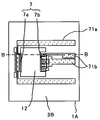
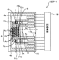
また、図3に示すように、ベース材2の電気絶縁層3aに形成された検出領域1aと対向する箇所は、エッチング処理により除去され、環状空洞部20となっている。環状空洞部20は、冷却部4と温度測定部5と相変化物質6A,6Bと同心となっている。また、図2、図3に示すように、基板1の検出領域1aと回路領域1bとを有する面(以下、おもて面という)と、反対側の面(以下、裏面という)の電気絶縁層3bには、基板1上の結露(凝集)を検知する凝集検出手段としての反射型フォトカプラ7が設けられている。フォトカプラ7の発光手段としての発光部7aは、裏面電気絶縁層3bを介して、環状空洞部20の中心に残ったベース材芯部21に設けられている。フォトカプラ7の受光手段である受光部7bは、環状空洞部20の外壁曲面20bと対向するように、環状空洞部20と同心円状に等間隔に、複数配置されている。環状空洞部20の内壁20aおよび外壁20bは鏡面状となっている。この環状空洞部20は、次のようにして、形成される。すなわち、裏面電気絶縁層3bパターンをマスクとして、基板1の構造に依存しないどの方位に対しても等速度の等方性エッチングにより、あるいは、Si単結晶基板であれば酸化剤を添加したフッ化水素酸を用いることにより、ベース材2に内壁20aおよび外壁20bが曲面鏡面状の環状空洞部20が形成される。   Further, as shown in FIG. 3, a portion facing the detection region 1 a formed in the electric insulating layer 3 a of the base material 2 is removed by an etching process to form an annular cavity 20. The annular cavity 20 is concentric with the cooling part 4, the temperature measuring part 5, and the phase change materials 6A and 6B. Also, as shown in FIGS. 2 and 3, electrical insulation between the surface (hereinafter referred to as the front surface) of the substrate 1 having the detection region 1a and the circuit region 1b and the opposite surface (hereinafter referred to as the back surface). The layer 3b is provided with a reflective photocoupler 7 as agglomeration detecting means for detecting dew condensation (aggregation) on the substrate 1. The light emitting part 7a as the light emitting means of the photocoupler 7 is provided on the base material core part 21 remaining in the center of the annular cavity part 20 via the back surface electrical insulating layer 3b. A plurality of light receiving portions 7b as light receiving means of the photocoupler 7 are arranged at equal intervals concentrically with the annular cavity 20 so as to face the outer wall curved surface 20b of the annular cavity 20. The inner wall 20a and the outer wall 20b of the annular cavity 20 are mirror-like. The annular cavity 20 is formed as follows. That is, with the back surface electrical insulating layer 3b pattern as a mask, fluorination with isotropic etching at an equal speed in any orientation independent of the structure of the substrate 1 or with an oxidizing agent added to a Si single crystal substrate By using hydrogen acid, an annular cavity 20 having a curved mirror surface on the inner wall 20 a and the outer wall 20 b is formed in the base material 2.

フォトカプラの発光部7aから出射された光は、図3の点線で示すように、環状空洞部20の曲面状の内壁20aに放射状に反射して拡散し、冷却電極4a上の環状の観測面8全体に照射される。電気絶縁層3aは、無色透明であるので、観測面8に結露が生じていないときは、観測面8に照射された光は、観測面8の下の冷却電極4aに入射し、正反射する。冷却電極4aにより反射された光は、環状空洞部20の外壁20bに反射し、受光部7bに入射する。一方、観測面8に結露が生じると、観測面8に照射された光は、観測面8上の結露により乱反射する。その結果、受光部7bに入射する光が減少し、観測面8に結露が生じたことを検知することができる。このように、結露が生じたことを検知したら、温度測定部5の温度を検出し、露点が計測される。ベース材2の厚み(環状空洞部20の深さ)、観測面8、発光部7a、受光部7bの配置位置を適宜設計することにより、発光部7aの光が、観測面8に入射し、観測面8(冷却電極4a)から反射した光が受光部7bに入射させることができる。このように、同一基板に凝集検出手段たるフォトカプラ7を設けることにより、精度よく凝集を検出することができ、高感度に凝集を検出することができる。   The light emitted from the light emitting portion 7a of the photocoupler is reflected and diffused radially on the curved inner wall 20a of the annular cavity 20 as shown by the dotted line in FIG. 3, and the annular observation surface on the cooling electrode 4a. The whole 8 is irradiated. Since the electrical insulating layer 3a is colorless and transparent, when no condensation occurs on the observation surface 8, the light irradiated on the observation surface 8 enters the cooling electrode 4a below the observation surface 8 and is regularly reflected. . The light reflected by the cooling electrode 4a is reflected by the outer wall 20b of the annular cavity 20 and enters the light receiving part 7b. On the other hand, when condensation occurs on the observation surface 8, the light irradiated on the observation surface 8 is irregularly reflected by the condensation on the observation surface 8. As a result, it is possible to detect that the light incident on the light receiving unit 7b is reduced and condensation is generated on the observation surface 8. Thus, if it detects that dew condensation has arisen, the temperature of the temperature measurement part 5 will be detected and a dew point will be measured. By appropriately designing the thickness of the base material 2 (depth of the annular cavity portion 20), the observation surface 8, the light emitting portion 7a, and the light receiving portion 7b, the light from the light emitting portion 7a is incident on the observation surface 8, Light reflected from the observation surface 8 (cooling electrode 4a) can be incident on the light receiving portion 7b. As described above, by providing the photocoupler 7 serving as the aggregation detection unit on the same substrate, the aggregation can be detected with high accuracy and the aggregation can be detected with high sensitivity.

回路領域1bの制御回路は、露点が計測されたら、予め温度測定部5で測定して、メモリに記憶しておいた雰囲気温度Cと露点Dとを用いて、相対湿度(%RH)を演算して求める。
相対湿度は、次のようにして求めることができる。
t℃における飽和水蒸気圧E(t)hPaを求めるTentesの式
E(t)=6.11×10{7.5t/(t+273.3)}・・・・(1)
を用い、下記の式を用いて、相対湿度(%RH)を、下記の式により算出する。
H=E(露点D)/E(雰囲気温度T)×100・・・・(2)
When the dew point is measured, the control circuit in the circuit area 1b calculates the relative humidity (% RH) using the ambient temperature C and the dew point D that are measured in advance by the temperature measuring unit 5 and stored in the memory. And ask.
The relative humidity can be obtained as follows.
Tentes' formula for obtaining saturated water vapor pressure E (t) hPa at t ° C. = 6.11 × 10 {7.5 t / (t + 273.3)} (1)
The relative humidity (% RH) is calculated by the following equation using the following equation.
H = E (dew point D) / E (atmosphere temperature T) × 100 (2)

また、図1に示すように、基板1のおもて面の電気絶縁層3aの熱電変換材料間には、貫通孔9が設けられている。これにより、放熱電極4bの熱が、電気絶縁層3aの冷却電極4a上の観測面8に伝播するのを抑制することができ、観測面8を良好に冷却することができる。また、図3に示すように、環状空洞部20は、放熱電極4bが形成される領域までは、形成されておらず、少なくとも、放熱電極4bは、電気絶縁層3aを介して、ベース材2と対向している。これにより、放熱電極4b付近の熱容量を大きくすることができ、観測面8に放熱電極4bの熱を伝播しにくくすることができる。   As shown in FIG. 1, through holes 9 are provided between the thermoelectric conversion materials of the electrically insulating layer 3 a on the front surface of the substrate 1. Thereby, it can suppress that the heat of the thermal radiation electrode 4b propagates to the observation surface 8 on the cooling electrode 4a of the electric insulation layer 3a, and the observation surface 8 can be cooled favorably. Further, as shown in FIG. 3, the annular cavity 20 is not formed up to the region where the heat dissipation electrode 4b is formed, and at least the heat dissipation electrode 4b is interposed between the base material 2 and the electric insulating layer 3a. Is facing. Thereby, the heat capacity in the vicinity of the heat radiation electrode 4 b can be increased, and the heat of the heat radiation electrode 4 b can be made difficult to propagate to the observation surface 8.

また、図3に示すように、環状空洞部20の中心に残ったベース材芯部21と、おもて面側の電気絶縁層3aとの間に隙間が形成されている。これにより、冷却電極4a、温度測定部5、相変化物質6A,6Bが形成された電気絶縁層3aの領域は、ベース材2と非接触となるので、冷却電極4a、温度測定部5、相変化物質6A,6B付近の熱容量を少なくすることができる。これにより、冷却電極4aで、観測面8をすばやく冷却することができ、また、温度測定部5を発熱させて、すばやく相変化物質6A,6Bを加熱することができる。また、冷却電極4a、温度測定部5、相変化物質6A,6Bが形成された領域の熱容量が少ないので、温度測定部5の温度応答を鋭敏にすることができ、冷却電極4a上の観測面8の温度や、相変化物質6A,6Bの温度を精度よく測定することができる。   Further, as shown in FIG. 3, a gap is formed between the base material core 21 remaining in the center of the annular cavity 20 and the electrical insulating layer 3a on the front surface side. Thereby, the region of the electrical insulating layer 3a in which the cooling electrode 4a, the temperature measuring unit 5, and the phase change materials 6A and 6B are formed is not in contact with the base material 2, so that the cooling electrode 4a, the temperature measuring unit 5, The heat capacity in the vicinity of the change substances 6A and 6B can be reduced. As a result, the observation surface 8 can be quickly cooled by the cooling electrode 4a, and the phase change materials 6A and 6B can be quickly heated by causing the temperature measurement unit 5 to generate heat. Further, since the heat capacity of the region where the cooling electrode 4a, the temperature measuring unit 5 and the phase change materials 6A and 6B are formed is small, the temperature response of the temperature measuring unit 5 can be made sharp, and the observation surface on the cooling electrode 4a 8 and the temperature of the phase change materials 6A and 6B can be measured with high accuracy.

さらに、図2に示すように、裏面の電気絶縁層3bの発光部7aと受光部7bとの間にも、複数の貫通孔12が設けられている。これにより、環状空間内に熱が篭るのを抑制することができ、冷却電極4a上の観測面8の温度や、相変化物質6A,6Bの温度を精度よく測定することができる。   Further, as shown in FIG. 2, a plurality of through holes 12 are also provided between the light emitting portion 7a and the light receiving portion 7b of the electrical insulating layer 3b on the back surface. Thereby, it is possible to suppress heat from flowing into the annular space, and it is possible to accurately measure the temperature of the observation surface 8 on the cooling electrode 4a and the temperature of the phase change materials 6A and 6B.

また、冷却電極4a(観測面8)と、温度測定部(加熱部)5と、相変化物質6A,6Bとを同心円状に配置することによって、相変化および凝集(結露)時などの時点で温度測定部5を均一な温度分布にすることができ、精度の高い露点計測および相変化の検出を行うことができる。また、温度測定部(加熱部)5の内側に相変化物質と配置することによって、相変化物質を最小面積に高密度集合させることができ、相変化物質を必要最小量の熱量で迅速に相転移温度にまで加熱することができる。また、冷却電極を円の中心寄りに配置することにより、少ない数で、冷却電極を高密度に配置することができ、観測面8をすばやく冷却することができる。   Further, by arranging the cooling electrode 4a (observation surface 8), the temperature measuring unit (heating unit) 5, and the phase change materials 6A and 6B in a concentric manner, at the time of phase change and aggregation (condensation), etc. The temperature measurement unit 5 can have a uniform temperature distribution, and the dew point can be measured and the phase change can be detected with high accuracy. Further, by arranging the phase change material inside the temperature measurement unit (heating unit) 5, the phase change material can be gathered in a minimum area in a high density, and the phase change material can be rapidly phased with a minimum amount of heat. It can be heated to the transition temperature. Further, by arranging the cooling electrodes closer to the center of the circle, the cooling electrodes can be arranged with a high density with a small number, and the observation surface 8 can be quickly cooled.

例えば、空洞の外周が直径φ150μm、円型の電気絶縁層の検出領域1aの直径φ110μmであって、電気絶縁層3aの厚みが2μmであり、相変化物質の外周が直径φ80μmとすると、相変化物質6AがInで156.5985℃、相変化物質6BがSnで231.928℃、の相転移温度であれば、2msecで温度キャリブレーションが完了し、―35℃から150℃の間の周囲温度測定は0.1msec、―35℃から100℃の間の露点は10msecで測定することができ、測定精度は±0.03℃が得られる。より高速にさせるにはさらに寸法を小さくすれば良い。   For example, if the outer periphery of the cavity is φ150 μm, the diameter of the detection region 1a of the circular electric insulating layer is φ110 μm, the thickness of the electric insulating layer 3a is 2 μm, and the outer periphery of the phase change material is φ80 μm, the phase change If the phase transition temperature of material 6A is 156.5985 ° C. for In and phase change material 6B is 231.928 ° C. for Sn, temperature calibration is completed in 2 msec and ambient temperature between −35 ° C. and 150 ° C. The measurement is 0.1 msec, the dew point between −35 ° C. and 100 ° C. is 10 msec, and the measurement accuracy is ± 0.03 ° C. In order to increase the speed, the size may be further reduced.

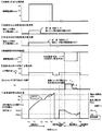
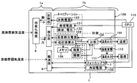
図4は、湿度センサ100の制御ブロック図である。
図に示すように温度較正手段としての温度キャリブレーション機能部101と温度や湿度を計測するための計測部102を有している。破線で囲んだキャリブレーション機能部101は、温度測定部5を加熱するための加熱電源103、相転移温度とそのときの温度測定部5の抵抗値などを記憶するため記憶手段たるメモリ106、相変化を検知するために用いる温度測定部5の電気抵抗値Rと時刻Tの関数などを演算する演算部107などで構成されている。一点鎖線で囲んだ計測部102は、温度計測を行うための温度検出電源104、温度測定部5の抵抗値を算出する抵抗値算出部112、比較部108、温度出力部109や湿度出力部111などを備えている。CPU113からキャリブレーション実行の信号が、加熱電源103に入力されると、加熱部としての温度測定部5が発熱する。同時に、温度測定部5の抵抗値が抵抗値算出部112で算出され、時刻と温度測定部5の抵抗値をメモリ106に収納する。そして、温度測定部5の抵抗値によって相変化物質の相転移を検出し、その時の温度測定部5の抵抗値を相変化物質の既知の相転移温度として、温度依存性を示す関係式を求め、メモリ106に記憶する。次に、CPU113から温度測定実行の信号が、温度検出電源104に入力されると、温度測定部5の抵抗値が抵抗値算出部112で算出され、比較部108で、算出された抵抗値と、先の温度依存性を示す関係式とを用いて、雰囲気の温度測定値として出力される。次に、観測面8が冷却され、フォトカップラ7で凝集が検出されると、温度測定実行の信号が、温度検出電源104に入力され、上述と同様にして、露点測定値として出力される。そして、温度測定値と露点測定値とにより湿度が湿度演算部110で演算され湿度測定値として出力される。
FIG. 4 is a control block diagram of the humidity sensor 100.
As shown in the figure, a temperature calibration function unit 101 as temperature calibration means and a measurement unit 102 for measuring temperature and humidity are provided. A calibration function unit 101 surrounded by a broken line includes a heating power source 103 for heating the temperature measuring unit 5, a memory 106 serving as a storage unit for storing a phase transition temperature and a resistance value of the temperature measuring unit 5 at that time, a phase The temperature measuring unit 5 used for detecting the change includes a calculation unit 107 that calculates a function of the electrical resistance value R and time T, and the like. A measurement unit 102 surrounded by a one-dot chain line includes a temperature detection power source 104 for performing temperature measurement, a resistance value calculation unit 112 for calculating a resistance value of the temperature measurement unit 5, a comparison unit 108, a temperature output unit 109, and a humidity output unit 111. Etc. When a calibration execution signal is input from the CPU 113 to the heating power supply 103, the temperature measurement unit 5 as a heating unit generates heat. At the same time, the resistance value of the temperature measuring unit 5 is calculated by the resistance value calculating unit 112, and the time and the resistance value of the temperature measuring unit 5 are stored in the memory 106. Then, the phase transition of the phase change material is detected based on the resistance value of the temperature measurement unit 5, and the relational expression indicating the temperature dependency is obtained by using the resistance value of the temperature measurement unit 5 at that time as the known phase transition temperature of the phase change material. And stored in the memory 106. Next, when a temperature measurement execution signal is input from the CPU 113 to the temperature detection power supply 104, the resistance value of the temperature measurement unit 5 is calculated by the resistance value calculation unit 112, and the calculated resistance value is calculated by the comparison unit 108. Using the relational expression indicating the temperature dependence, the temperature is output as a measured value of the atmosphere. Next, when the observation surface 8 is cooled and aggregation is detected by the photocoupler 7, a temperature measurement execution signal is input to the temperature detection power source 104 and output as a dew point measurement value in the same manner as described above. Then, the humidity is calculated by the humidity calculation unit 110 based on the temperature measurement value and the dew point measurement value, and is output as the humidity measurement value.

次に、本実施形態の湿度センサ100における相変化物質の相転移を用いたキャリブレーションの原理について概説する。ここでは相変化物質の相転移を相変化物質の温度(熱)変化で検出する場合について、説明する。
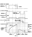
図5は時間推移における相変化物質の温度変化と、温度測定部5の抵抗変化とを示す特性図である。図5に示すように、相変化物質を加熱していき、相変化物質が相転移温度(融点(凝固点):Mpa)になると吸熱反応が生じる。相変化物質が固体であれば温度が上がっていくと相転移温度にて液体となりはじめ、全てが液体となる期間は相転移温度MPaを維持し、全てが液体となった以降は再び温度が上昇する。そのため、温度測定部5の電気抵抗値が不連続な傾向となる部分が出現する。すなわち、図5に示すように、温度測定部5の電気抵抗値R2のとき、温度が相転移温度であると判定できる。よって、温度依存性を有する抵抗体である温度測定部5の抵抗値を測定しておき、測定抵抗値が抵抗値R2となったときの温度を既知の相転移温度とする温度較正を行う。このように、相転移温度と電気抵抗値との関係が1対1の関係となり、この関係を用いることによりキャリブレーションを行うことができる。
Next, the principle of calibration using the phase transition of the phase change substance in the humidity sensor 100 of the present embodiment will be outlined. Here, the case where the phase transition of the phase change material is detected by the temperature (heat) change of the phase change material will be described.
FIG. 5 is a characteristic diagram showing the temperature change of the phase change material over time and the resistance change of the temperature measurement unit 5. As shown in FIG. 5, when the phase change material is heated and the phase change material reaches the phase transition temperature (melting point (freezing point): Mpa), an endothermic reaction occurs. If the phase change material is solid, it begins to become liquid at the phase transition temperature as the temperature rises, maintains the phase transition temperature MPa during the period when everything is liquid, and rises again after all becomes liquid. To do. Therefore, a portion where the electric resistance value of the temperature measuring unit 5 tends to be discontinuous appears. That is, as shown in FIG. 5, when the electrical resistance value R2 of the temperature measurement unit 5 is used, it can be determined that the temperature is the phase transition temperature. Therefore, the resistance value of the temperature measuring unit 5 that is a temperature-dependent resistor is measured, and temperature calibration is performed with the temperature when the measured resistance value becomes the resistance value R2 as the known phase transition temperature. Thus, the relationship between the phase transition temperature and the electric resistance value is a one-to-one relationship, and calibration can be performed by using this relationship.

相変化物質を加熱する加熱部(本実施形態においては、温度測定部5)の熱容量を小さくし、かつ均一な温度領域に形成することにより、相変化の時点をより正確に検出できる。また、本実施形態においては、相変化物質を加熱する加熱手段として、温度測定部5を用いている。相変化物質を加熱するときは、温度測定部5にジュール熱が生じるような大きな電流を温度測定部5に流す。図5に示すように、相変化物質が固体から液体へ相転移が発生すると、相変化物質が吸熱反応を示し、相変化開始から終了まで温度が変化しないので温度が維持され、温度測定部5でもある抵抗体の電気抵抗値の増加傾向が平行状態へ変化する。相変化物質の転移熱量(潜熱)が大きく、検出領域全体の熱容量に対して相変化物質の熱容量が占める割合が大きいほど、この吸熱反応の時間(温度が変化しない時間)を長くすることができ、確実に相変化物質の相変位を検出することができ、好ましい。回路領域1bの制御回路は、温度測定部5に印加した電圧値と、温度測定部5に流れた電流値とから、時刻T0の温度測定部5の電気抵抗値と、時刻T1の温度測定部5の電気抵抗値とを推移データとして記憶する。そして、時刻T0の電気抵抗値と時刻T1の電気抵抗値とから、抵抗値Rと時刻Tとの関数(一次関数:R=aT+b)が演算される。この関数により求められた時刻T1後の抵抗値と、測定した時刻T1後の抵抗値Rとを比較していく。すると、時刻T2後で関数にフィットしないデータが生じ、相変化物質が相転移したことを検知することができる。   The time point of the phase change can be detected more accurately by reducing the heat capacity of the heating unit (in this embodiment, the temperature measuring unit 5) for heating the phase change material and forming it in a uniform temperature region. In the present embodiment, the temperature measuring unit 5 is used as a heating means for heating the phase change material. When the phase change material is heated, a large current that causes Joule heat in the temperature measurement unit 5 is passed through the temperature measurement unit 5. As shown in FIG. 5, when the phase change material undergoes a phase transition from a solid to a liquid, the phase change material exhibits an endothermic reaction, and the temperature does not change from the start to the end of the phase change. However, the increasing tendency of the electrical resistance value of a certain resistor changes to a parallel state. The endothermic reaction time (the time during which the temperature does not change) can be increased as the amount of heat of transition (latent heat) of the phase change material is large and the ratio of the heat capacity of the phase change material to the heat capacity of the entire detection region is large. It is preferable because the phase change of the phase change substance can be detected with certainty. The control circuit in the circuit region 1b is configured to calculate the electrical resistance value of the temperature measuring unit 5 at time T0 and the temperature measuring unit at time T1 from the voltage value applied to the temperature measuring unit 5 and the current value flowing through the temperature measuring unit 5. The electric resistance value of 5 is stored as transition data. Then, a function (linear function: R = aT + b) of the resistance value R and the time T is calculated from the electric resistance value at the time T0 and the electric resistance value at the time T1. The resistance value after time T1 obtained by this function is compared with the measured resistance value R after time T1. Then, after time T2, data that does not fit the function is generated, and it can be detected that the phase change material has undergone phase transition.

相変化物質の相転移を検知したら、温度測定部5の電気抵抗値R2が既知の温度Mpaとしてメモリに保存し、下記に示す温度依存性を示す関係式を補正する。温度測定部5で、露点や雰囲気温度を測定するときは、温度測定部5に対しジュール発熱させないように微弱な電流を供給して、そのときの温度測定部5の電気抵抗値を測定する。そして、メモリに記憶されている下記に示す温度依存性を示す関係式と、温度測定部5の既知の抵抗温度係数TCRとを用いることによって、温度測定部5の抵抗値から、温度を検出する。
温度依存性を示す関係式:(抵抗値R、温度S、温度係数(TCR)α
R=R0*(1+α*S)・・・・(式3)
例えば、温度測定部が白金抵抗体の場合、温度係数(TCR)αは、α=3.9083E−03(0℃〜850℃)となる。
温度キャリブレーションにおいては、上述の抵抗値R2と温度MPaとの関係に基づいて、上記R0が補正される。
When the phase transition of the phase change material is detected, the electrical resistance value R2 of the temperature measuring unit 5 is stored in the memory as a known temperature Mpa, and the following relational expression indicating temperature dependence is corrected. When the dew point or the ambient temperature is measured by the temperature measuring unit 5, a weak current is supplied to the temperature measuring unit 5 so as not to generate Joule heat, and the electrical resistance value of the temperature measuring unit 5 at that time is measured. Then, the temperature is detected from the resistance value of the temperature measurement unit 5 by using the following relational expression indicating the temperature dependency stored in the memory and the known resistance temperature coefficient TCR of the temperature measurement unit 5. .
Relational expression showing temperature dependence: (resistance value R, temperature S, temperature coefficient (TCR) α
R = R0 * (1 + α * S) (Formula 3)
For example, when the temperature measurement unit is a platinum resistor, the temperature coefficient (TCR) α is α = 3.9083E-03 (0 ° C. to 850 ° C.).
In the temperature calibration, R0 is corrected based on the relationship between the resistance value R2 and the temperature MPa.

また、本実施形態の温度の実用に必要な精度は、0〜850℃の範囲で±0.1℃の精度で十分であるので、下記式4の温度依存性を示す関係式のβ×Sを0として線形な一次関数を、温度依存性を示す関係式として用いているが、下記式4に示す2次関数の温度依存性を示す関係式を用いてもよい。下記式4に示す2次関数の温度依存性を示す関係式を用いることで、0〜419.527℃の範囲で±0.01の精度を得ることができ、抵抗値−温度特性の精度を更に高めることもできる。
R=R0*(1+α*S+β*S)・・・・(式4)
例えば、白金抵抗体の温度係数(TCR)は
α=3.9083E−03、β=−5.7750E−07(0℃〜850℃)
Further, the accuracy required for practical use of the temperature of the present embodiment is ± 0.1 ° C. in the range of 0 to 850 ° C., and therefore β × S of the relational expression showing the temperature dependence of the following equation 4. A linear function with 2 as 0 is used as a relational expression showing temperature dependence, but a relational expression showing the temperature dependence of a quadratic function shown in the following expression 4 may be used. By using the relational expression showing the temperature dependence of the quadratic function shown in the following equation 4, an accuracy of ± 0.01 can be obtained in the range of 0-419.527 ° C., and the accuracy of the resistance value-temperature characteristic is improved. It can be further increased.
R = R0 * (1 + α * S + β * S 2 ) (Formula 4)
For example, the temperature coefficient (TCR) of the platinum resistor is α = 3.9083E-03, β = −5.7750E-07 (0 ° C. to 850 ° C.)

図6は、相変化物質を加熱するときに温度測定部5に流す電流に対する温度変化及び温度測定部5の抵抗値変化を示す特性図である。この図6においては、相変化物質が液体から気体に相変化する例であり、熱容量の変化で相転移を検知する例である。図6に示すように、温度測定部5へ流す電流値を増加させ、沸点Bpに達した時に相変化物質が相転移する。相変化物質が液体から気体へ既知の温度(昇華点又は沸点:Bp)で相転移すると、相変化物質は蒸散が完了するまで、吸熱反応により温度上昇しない不連続な特性として現れる。しかし、蒸散により相変化物質の質量が減少してゆくため、上記温度上昇しない不連続な特性は、図6に現れないほど、ごく短時間である。このため、相変化物質が液体から気体に相変化する場合は、相変化物質が固定から液体へ相変化する場合のように、吸熱反応により温度上昇しない不連続な特性を検出することは難しい。そこで、相変化物質が液体から気体に相変化する場合は、蒸散前の温度上昇と、蒸散後の温度上昇の違いに基づいて、相転移温度を検知する。具体的には、相変化物質が蒸散すると、検出領域の温度測定部周辺の熱容量が相変化物質の分減少する。相変化物質の蒸散により熱容量が減少することにより、温度上昇および温度測定部5の増加量(傾き)が、相変化物質が蒸散する前に比べて大きくなり、図6に示すように、温度(電気抵抗値)は、不連続な特性として顕著に現れるので、この不連続開始点(ごくわずかな温度上昇しない領域における後端)を検出する。よって、この場合も、相変化物質加熱直後に得られたデータから、温度測定部5の電気抵抗値Rと時刻Tの関数(一次関数:R=aT+b)を演算し、この関数にフィットしないデータが生じれば相変化物質が相転移したことを検知することができる。相変化物質の相転移を検知したら、温度測定部5の電気抵抗値R2が既知の温度Mpaとしてメモリに保存する。温度測定部5で、露点や雰囲気温度を測定するときは、温度測定部5に対しジュール発熱させないように微弱な電流を供給して、そのときの温度測定部5の電気抵抗値を測定する。そして、上述同様、温度キャリブレーションにより補正された温度依存性を示す関係式を用いて、温度が演算される。   FIG. 6 is a characteristic diagram showing a temperature change with respect to a current passed through the temperature measuring unit 5 and a resistance value change of the temperature measuring unit 5 when the phase change material is heated. FIG. 6 is an example in which the phase change material undergoes a phase change from a liquid to a gas, and is an example in which a phase transition is detected by a change in heat capacity. As shown in FIG. 6, the value of the current passed through the temperature measuring unit 5 is increased, and the phase change material undergoes phase transition when the boiling point Bp is reached. When the phase change material undergoes a phase transition from a liquid to a gas at a known temperature (sublimation point or boiling point: Bp), the phase change material appears as a discontinuous property that does not increase in temperature due to endothermic reaction until transpiration is completed. However, since the mass of the phase change material decreases due to transpiration, the discontinuous characteristics that do not increase in temperature are so short that they do not appear in FIG. For this reason, when the phase change material undergoes a phase change from liquid to gas, it is difficult to detect discontinuous characteristics in which the temperature does not increase due to endothermic reaction, as in the case where the phase change material undergoes a phase change from stationary to liquid. Therefore, when the phase change material undergoes a phase change from liquid to gas, the phase transition temperature is detected based on the difference between the temperature increase before transpiration and the temperature increase after transpiration. Specifically, when the phase change material evaporates, the heat capacity around the temperature measurement unit in the detection region is reduced by the amount of the phase change material. As the heat capacity decreases due to the transpiration of the phase change material, the temperature rise and the increase (slope) of the temperature measuring unit 5 become larger than before the phase change material transpirations, and as shown in FIG. Since the electric resistance value appears remarkably as a discontinuous characteristic, this discontinuity starting point (the rear end in a region where the temperature does not rise very slightly) is detected. Therefore, also in this case, a function (primary function: R = aT + b) of the electrical resistance value R and time T of the temperature measurement unit 5 is calculated from data obtained immediately after the phase change material heating, and data that does not fit this function If this occurs, it can be detected that the phase change material has undergone phase transition. When the phase transition of the phase change material is detected, the electrical resistance value R2 of the temperature measuring unit 5 is stored in the memory as a known temperature Mpa. When the dew point or the ambient temperature is measured by the temperature measuring unit 5, a weak current is supplied to the temperature measuring unit 5 so as not to generate Joule heat, and the electrical resistance value of the temperature measuring unit 5 at that time is measured. As described above, the temperature is calculated using the relational expression indicating the temperature dependency corrected by the temperature calibration.

先の図1に示すように、本実施形態においては、2種類の相変化物質6A,6Bを備えている。これら2種類の相変化物質6A,6Bは、互いの相転移温度が異なる物質である。このように、相転移温度が互いに異なる2種類の相変化物質6A,6Bを用いることにより、抵抗温度係数TCRをメモリに記憶しておく必要がなくなる。以下に、具体的説明する。   As shown in FIG. 1, the present embodiment includes two types of phase change substances 6A and 6B. These two types of phase change materials 6A and 6B are materials having different phase transition temperatures. As described above, by using the two types of phase change materials 6A and 6B having different phase transition temperatures, it is not necessary to store the resistance temperature coefficient TCR in the memory. Specific description will be given below.

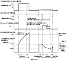
図7は異なる相転移温度の2つの相変化物質6A,6Bにおいて時間推移に対する温度変化を示す特性図であり、図8は、温度キャリブレーション、温度、露点検出と湿度出力の入出力信号のタイミングチャートであり、図9は、フローチャートである。
CPUからキャリブレーション実行の信号が、湿度センサ1に入力されると、温度測定部5に相変化を加熱するための加熱電流が印加され、各相変化物質6A,6Bが加熱される。そして、時刻T2で一方の相変化物質6Aが相転移する温度(相変化物質6A固有の既知の値である融点(凝固点):Mpa)になる。更に、加熱電流を供給し続けて温度を上昇させると、時刻T4で他方の相変化物質6Bが相転移する温度(相変化物質6B固有の既知の値である融点(凝固点):Mpb(>Mpa))になる。
FIG. 7 is a characteristic diagram showing temperature changes with time in two phase change materials 6A and 6B having different phase transition temperatures. FIG. 8 shows timings of input / output signals of temperature calibration, temperature and dew point detection, and humidity output. FIG. 9 is a flowchart.
When a calibration execution signal is input from the CPU to the humidity sensor 1, a heating current for heating the phase change is applied to the temperature measuring unit 5, and the phase change materials 6 </ b> A and 6 </ b> B are heated. At time T2, the temperature at which one phase change material 6A undergoes phase transition (melting point (freezing point): Mpa, which is a known value unique to phase change material 6A) is reached. Further, when the heating current is continuously supplied and the temperature is raised, the temperature at which the other phase change material 6B undergoes phase transition at time T4 (melting point (freezing point), which is a known value unique to the phase change material 6B): Mpb (> Mpa ))become.

このように相変化物質が2種類あるときは、上述したように、相変化物質加熱直後に求めた温度測定部5の電気抵抗値Rと時刻Tの関数(一次関数:R=aT+b)を用いた場合、他方の相変化物質6Bの相変化を検知することができないので、以下のようにして、2種類の相変化物質6A,6Bの相変化を検知する。すなわち、固体から液体へ相転移を完了するまでは吸熱反応によって印加電力を増しても温度の上昇はなくΔR=0であるので、時刻T2において一方の相変化物質6Aは既知の相転移温度Mpaになったことを検出することができる。同様に、時刻T4において他方の相変化物質6Bは既知の相転移温度Mpbになったと検出する。   Thus, when there are two types of phase change materials, as described above, the function (primary function: R = aT + b) of the electrical resistance value R and time T of the temperature measurement unit 5 obtained immediately after the phase change material heating is used. If this is the case, the phase change of the other phase change material 6B cannot be detected, so the phase changes of the two types of phase change materials 6A and 6B are detected as follows. That is, until the phase transition from the solid to the liquid is completed, even if the applied power is increased by the endothermic reaction, the temperature does not increase and ΔR = 0. Therefore, at time T2, one phase change material 6A has a known phase transition temperature Mpa. Can be detected. Similarly, at time T4, the other phase change material 6B is detected to have reached a known phase transition temperature Mpb.

ΔRが、0となったら、制御回路は、図10に示すように、相転移温度MPaにおける温度測定部5の電気抵抗値Raと、相転移温度MPbにおける温度測定部5の電気抵抗値Rbに基づいて、温度依存性の関数を求め、メモリに記憶する。そして、温度測定部5への加熱電流の印加をOFFにして、温度キャリブレーションが終了する。   When ΔR becomes 0, the control circuit sets the electrical resistance value Ra of the temperature measurement unit 5 at the phase transition temperature MPa and the electrical resistance value Rb of the temperature measurement unit 5 at the phase transition temperature MPb, as shown in FIG. Based on this, a temperature-dependent function is obtained and stored in the memory. Then, the application of the heating current to the temperature measuring unit 5 is turned off, and the temperature calibration is completed.

このように、2つの異なる相変化物質6A,6Bを用いて、温度キャリブレーションが行われることにより、高精度の温度目盛が付与できる。また、温度依存性の関数を求めるので、未知の抵抗温度係数(TCR)の抵抗体材料を用いることができる。   As described above, by performing temperature calibration using two different phase change materials 6A and 6B, a highly accurate temperature scale can be provided. In addition, since a temperature-dependent function is obtained, a resistor material having an unknown resistance temperature coefficient (TCR) can be used.

また、より高精度な測定値を得るためには、国際温度目盛り(ITS−90)に示されている標準物質の凝固点の中でも、温度検出範囲に対してできるだけ相転移温度が近いことが好ましい。例えば、一般電子機器に用いられているIC温度センサの測定範囲である−40から+125℃に相当する用途であれば、相変化物質6AにIn(Mpa=156.5985℃)相変化物質6BにSn(Mpb=231.928℃)を選択し、温度測定部5にPt(0℃〜850℃では線形)を用いることで、MpaからMpbまでの範囲以外の温度領域でも高精度な測定値を得ることができる。また、本実施形態では、2種類の相変化物質を6A,6B用いているが、先の式4に示すように、温度依存性を示す関係式として、2次関数を用いる場合、温度係数(TCR)α、βを用いずに、温度依存性を示す関数を算出するには少なくとも、3点の異なる既知の相転移温度が必要となる。この場合は、互いの相転移温度が異なる3種類以上の相変化物質を備えればよい。   Moreover, in order to obtain a more accurate measurement value, it is preferable that the phase transition temperature is as close as possible to the temperature detection range among the freezing points of the standard substances shown in the international temperature scale (ITS-90). For example, in an application corresponding to −40 to + 125 ° C., which is the measurement range of an IC temperature sensor used in general electronic equipment, the phase change material 6A includes In (Mpa = 156.5985 ° C.) and the phase change material 6B includes By selecting Sn (Mpb = 231.929 ° C.) and using Pt (linear at 0 ° C. to 850 ° C.) for the temperature measuring unit 5, highly accurate measurement values can be obtained even in a temperature range other than the range from Mpa to Mpb. Can be obtained. In the present embodiment, two types of phase change materials 6A and 6B are used. However, as shown in Equation 4, when a quadratic function is used as a relational expression indicating temperature dependence, a temperature coefficient ( TCR) To calculate a function indicating temperature dependence without using α and β, at least three different known phase transition temperatures are required. In this case, three or more kinds of phase change materials having different phase transition temperatures may be provided.

次に、所定のタイミングで湿度測定が実行されると、CPUから雰囲気温度測定実行の信号が、湿度センサ100に入力される。なお、本実施形態の湿度センサは、熱容量が小さいので、温度キャリブレーション実行後、すばやく雰囲気温度にまで戻るので、温度キャリブレーション実行後、0.1sec経過すれば、精度よく雰囲気温度を測定することができる。CPUから雰囲気温度測定実行の信号が、湿度センサ100に入力されると、温度測定部5に温度検出用電流が印加され、温度測定部5に印加された電圧値V5が検出されて、温度測定部5の抵抗値V5/Isが算出される。次に、温度キャリブレーションに求めた温度依存性を示す関係式を用いて、図10に示すように、雰囲気温度C5が算出され、出力される。   Next, when the humidity measurement is executed at a predetermined timing, an ambient temperature measurement execution signal is input to the humidity sensor 100 from the CPU. In addition, since the humidity sensor of this embodiment has a small heat capacity, it quickly returns to the ambient temperature after the temperature calibration is performed. Therefore, the ambient temperature can be accurately measured if 0.1 sec elapses after the temperature calibration is performed. Can do. When an ambient temperature measurement execution signal is input from the CPU to the humidity sensor 100, a temperature detection current is applied to the temperature measurement unit 5, and the voltage value V5 applied to the temperature measurement unit 5 is detected to measure the temperature. The resistance value V5 / Is of the unit 5 is calculated. Next, as shown in FIG. 10, the ambient temperature C5 is calculated and output using the relational expression indicating the temperature dependency obtained for the temperature calibration.

CPUは、湿度センサ100から雰囲気温度C5を受信したら、露点測定実行信号を、湿度センサ100へ送信する。湿度センサ100は、CPUから露点測定実行信号を受信したら、冷却部4の熱電変換材料4cに冷却電流を印加して、冷却電極4a上の観測面8の冷却を開始する。また、フォトカプラ7の発光部7aにバイアスを印加して、観測面8に向けて光を照射する。冷却開始直後は、発光部7aからの光が、観測面8直下の冷却電極4aに反射して、受光部7bに入射するので、受光部7bから所定出力電圧V0が出力される。そして、雰囲気中の水蒸気が観測面8に結露すると、発光部7aからの光が観測面8の結露によって乱反射し、受光部7bに入射する光量が減少する。その結果、76に示すように、受光部7bの出力電圧が低下する。制御回路は、受光部7bからの出力電圧の低下を検知したら、凝集を検知したと判定する。凝集が検知されたら、冷却電流をOFFにするとともに、温度測定部5に印加された電圧値V8を検出して、温度測定部5の抵抗値V8/Isが算出される。次に、温度キャリブレーションにより求めた温度依存性を示す関係式を用いて、図10に示すように、雰囲気温度C8が算出され、出力される。そして、発光部7aへの印加電圧と、温度測定部5への温度測定電流とをOFFにする。   When the CPU receives the ambient temperature C5 from the humidity sensor 100, the CPU transmits a dew point measurement execution signal to the humidity sensor 100. When receiving the dew point measurement execution signal from the CPU, the humidity sensor 100 applies a cooling current to the thermoelectric conversion material 4c of the cooling unit 4 and starts cooling the observation surface 8 on the cooling electrode 4a. In addition, a bias is applied to the light emitting portion 7 a of the photocoupler 7 to irradiate light toward the observation surface 8. Immediately after the start of cooling, the light from the light emitting portion 7a is reflected by the cooling electrode 4a immediately below the observation surface 8 and enters the light receiving portion 7b, so that the predetermined output voltage V0 is output from the light receiving portion 7b. When water vapor in the atmosphere condenses on the observation surface 8, light from the light emitting portion 7a is irregularly reflected by condensation on the observation surface 8, and the amount of light incident on the light receiving portion 7b is reduced. As a result, as indicated by 76, the output voltage of the light receiving portion 7b is lowered. When the control circuit detects a decrease in the output voltage from the light receiving unit 7b, it determines that aggregation has been detected. When the aggregation is detected, the cooling current is turned off and the voltage value V8 applied to the temperature measurement unit 5 is detected, and the resistance value V8 / Is of the temperature measurement unit 5 is calculated. Next, as shown in FIG. 10, the ambient temperature C8 is calculated and output using a relational expression showing the temperature dependence obtained by the temperature calibration. Then, the voltage applied to the light emitting unit 7a and the temperature measuring current to the temperature measuring unit 5 are turned off.

次に、制御回路は、得られた雰囲気温度C5と、露点D8と、予めメモリに記憶されている相対湿度を求める関数上記式(1),式(2)に基づいて、湿度を算出し、出力する。   Next, the control circuit calculates the humidity based on the obtained atmospheric temperature C5, the dew point D8, and the functions for obtaining the relative humidity stored in the memory in advance, the above formulas (1) and (2), Output.

このように、本実施形態においては、温度キャリブレーションを行うので、精度の高い雰囲気温度、露点を得ることができ、精度の高い湿度測定を行うことができる。   Thus, in this embodiment, since temperature calibration is performed, a highly accurate atmospheric temperature and dew point can be obtained, and highly accurate humidity measurement can be performed.

次に、本実施形態の変形例について、説明する。   Next, a modification of this embodiment will be described.
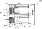
[変形例1]
図11は、変形例1の湿度センサの概略平面図である。
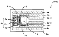
図11に示すように、この変形例1の湿度センサ100Aは、検出領域を備えた検知基板1Aと、回路領域1bを備えた回路基板1Bとを別々に設けた構成である。これにより、回路基板1Bは、測定する雰囲気(気体)などに暴露されていないところに設けることができ、回路領域(回路基板)の化学的劣化などを抑えることができる。
[Modification 1]
FIG. 11 is a schematic plan view of a humidity sensor according to the first modification.
As shown in FIG. 11, the humidity sensor 100A according to the first modification has a configuration in which a detection board 1A having a detection area and a circuit board 1B having a circuit area 1b are separately provided. Thereby, the circuit board 1B can be provided in a place where it is not exposed to the atmosphere (gas) to be measured, and chemical deterioration of the circuit region (circuit board) can be suppressed.

[変形例2]
図12は、変形例2の湿度センサ100Bの概略平面図である。
図12に示す変形例2の湿度センサ100Bは、温度測定部5と、加熱部11とを別々に設けた構成である。加熱部11は、温度測定部5などと同心円状に設けられ、温度測定部5と相変化物質6A,6Bの間に設けられている。
[Modification 2]
FIG. 12 is a schematic plan view of a humidity sensor 100B according to the second modification.
The humidity sensor 100B of Modification 2 shown in FIG. 12 has a configuration in which the temperature measurement unit 5 and the heating unit 11 are provided separately. The heating unit 11 is provided concentrically with the temperature measurement unit 5 and the like, and is provided between the temperature measurement unit 5 and the phase change materials 6A and 6B.

図13は、変形例2の湿度センサ100Bにおける温度キャリブレーション、温度、露点検出と湿度出力の入出力信号のタイミングチャートであり、図14は、フローチャートである。
図13に示すように、温度キャリブレーションが実行されると、加熱電源から加熱部11に加熱電流が供給して、相変化物質6A、6Bが加熱されるとともに、温度測定部5に温度検出用電流が印加され、温度が検知される。そして、上述と同様にΔR=0を検知して、相変化物質6Aの相変化および相変化物質6Bの相変化を検出し、そのときの温度測定部5の抵抗値と、既知の相転移温度Mpa、Mpbとから、温度依存性の関数を求め、メモリに記憶する。その後、湿度検知信号を受信したら、上述と同様にして、雰囲気温度測定後、露点を測定し、雰囲気温度と露点に基づいて、湿度を求める。
FIG. 13 is a timing chart of input / output signals of temperature calibration, temperature / dew point detection, and humidity output in the humidity sensor 100B of the second modification, and FIG. 14 is a flowchart.
As shown in FIG. 13, when the temperature calibration is performed, a heating current is supplied from the heating power source to the heating unit 11 to heat the phase change materials 6A and 6B and to the temperature measurement unit 5 for temperature detection. A current is applied and the temperature is sensed. Then, similarly to the above, ΔR = 0 is detected to detect the phase change of the phase change material 6A and the phase change of the phase change material 6B, and the resistance value of the temperature measurement unit 5 at that time and the known phase transition temperature A temperature dependence function is obtained from Mpa and Mpb and stored in the memory. Thereafter, when a humidity detection signal is received, the dew point is measured after measuring the ambient temperature in the same manner as described above, and the humidity is obtained based on the ambient temperature and the dew point.

[変形例3]
図15は、変形例3の湿度センサ100Cの概略平面図である。
図15に示すように、この変形例3の湿度センサ100Cは、相変化物質6を、ひとつにしたものである。
図16は、変形例3の湿度センサ100Cにおける温度キャリブレーション、温度、露点検出と湿度出力の入出力信号のタイミングチャートであり、図17は、フローチャートである。図16、図17に示すように、温度測定部5の加熱電流を供給して、相変化物質6を加熱する。そして、上述と同様にΔR=0を検知して、相変化物質6の相変化を検出し、そのときの温度測定部5の抵抗値を算出する。また、ここでは、抵抗値の時間微分値ΔRが0か否かで、相変化物質6の相変化を検知しているが、上述したように、一次関数(R=aT+b)を求め、算出した抵抗値が関数にフィットしているか否かで、相変化を検知してもよい。相変化を検知したら、抵抗値と、既知の相転移温度Mpaと、上記(式3)の温度依存性を示す関数R=R0*(1+α*S)を補正して、温度キャリブレーションを終了する。その後、湿度測定信号を受信したら、上述同様、雰囲気温度測定後、冷却部4で観測面を冷却して、観測面に水蒸気を結露させる。そして、フォトカプラで観測面の結露を検知したら、温度測定部5の抵抗値を求め、求めた抵抗値と温度キャリブレーションで補正した温度依存性を示す関数とを用いて、露点を計測し、露点と雰囲気温度とから、湿度を算出する。
[Modification 3]
FIG. 15 is a schematic plan view of a humidity sensor 100C according to the third modification.
As shown in FIG. 15, the humidity sensor 100 </ b> C according to the third modification includes a single phase change material 6.
FIG. 16 is a timing chart of input / output signals of temperature calibration, temperature and dew point detection, and humidity output in the humidity sensor 100C of the third modification, and FIG. 17 is a flowchart. As shown in FIGS. 16 and 17, the heating current of the temperature measuring unit 5 is supplied to heat the phase change material 6. Then, ΔR = 0 is detected in the same manner as described above to detect the phase change of the phase change material 6, and the resistance value of the temperature measurement unit 5 at that time is calculated. Here, the phase change of the phase change material 6 is detected based on whether or not the time differential value ΔR of the resistance value is 0, but as described above, a linear function (R = aT + b) is obtained and calculated. The phase change may be detected based on whether or not the resistance value fits the function. When the phase change is detected, the resistance value, the known phase transition temperature Mpa, and the function R = R0 * (1 + α * S) indicating the temperature dependence of the above (formula 3) are corrected, and the temperature calibration is completed. . Thereafter, when a humidity measurement signal is received, the observation surface is cooled by the cooling unit 4 after the atmospheric temperature is measured, and water vapor is condensed on the observation surface, as described above. Then, when dew condensation on the observation surface is detected by the photocoupler, the resistance value of the temperature measurement unit 5 is obtained, and the dew point is measured using the obtained resistance value and the function indicating the temperature dependency corrected by the temperature calibration, Humidity is calculated from the dew point and the ambient temperature.

[変形例4]
次に、変形例4の湿度センサ100Dについて、説明する。
上述では、温度測定部を加熱手段として用いているが、この変形例4の湿度センサ100Dでは、冷却部4の冷却電極4aを加熱手段として用いるものであり、構成は、先の図15に示した湿度センサと同様な構成である。
図18は、変形例4の湿度センサ100Dの温度キャリブレーション、温度、露点検出と湿度出力の入出力信号のタイミングチャートであり、図19は、フローチャートである。
まず、冷却部4に加熱電流を供給するとともに、温度測定部5に温度検出用電流を供給する。加熱電流は、正極性の電流、すなわち、冷却時とは逆向きに流れる電流であり、これにより、放熱電極4bが吸熱し、相変化物質6の近傍に配置された冷却電極4aが放熱する。これにより、冷却電極4aにより、相変化物質6が加熱される。そして、上述同様、温度測定部5のΔR=0を検知して、相変化物質6の相変化を検出し、そのときの温度測定部5の抵抗値を算出する。相変化を検知したら、抵抗値と、既知の相転移温度Mpaと、上記(式3)の温度依存性を示す関数R=R0*(1+α*S)を補正して、温度キャリブレーションを終了する。その後、露点を検出するときは、冷却部に負極性の電流を印加し、冷却電極を吸熱、放熱電極を放熱にして、冷却電極で観測面を冷却する。そして、フォトカプラで観測面の結露を検知したら、温度測定部5の抵抗値を求め、求めた抵抗値と温度キャリブレーションで補正した温度依存性を示す関数とを用いて、露点を計測し、露点と雰囲気温度とから、湿度を算出する。
[Modification 4]
Next, a humidity sensor 100D of Modification 4 will be described.
In the above description, the temperature measurement unit is used as the heating unit. However, in the humidity sensor 100D of the fourth modification, the cooling electrode 4a of the cooling unit 4 is used as the heating unit, and the configuration is shown in FIG. The configuration is the same as that of the humidity sensor.
FIG. 18 is a timing chart of input / output signals of temperature calibration, temperature / dew point detection, and humidity output of the humidity sensor 100D of the fourth modification, and FIG. 19 is a flowchart.
First, a heating current is supplied to the cooling unit 4 and a temperature detection current is supplied to the temperature measuring unit 5. The heating current is a positive current, that is, a current that flows in the opposite direction to that during cooling, whereby the heat dissipation electrode 4b absorbs heat and the cooling electrode 4a disposed near the phase change material 6 dissipates heat. Thereby, the phase change material 6 is heated by the cooling electrode 4a. Then, as described above, ΔR = 0 of the temperature measuring unit 5 is detected to detect the phase change of the phase change material 6 and the resistance value of the temperature measuring unit 5 at that time is calculated. When the phase change is detected, the resistance value, the known phase transition temperature Mpa, and the function R = R0 * (1 + α * S) indicating the temperature dependence of the above (formula 3) are corrected, and the temperature calibration is completed. . Thereafter, when the dew point is detected, a negative current is applied to the cooling part, the cooling electrode absorbs heat and the heat dissipation electrode dissipates heat, and the observation surface is cooled by the cooling electrode. Then, when dew condensation on the observation surface is detected by the photocoupler, the resistance value of the temperature measurement unit 5 is obtained, and the dew point is measured using the obtained resistance value and the function indicating the temperature dependency corrected by the temperature calibration, Humidity is calculated from the dew point and the ambient temperature.

[変形例5]
図20は、変形例5の湿度センサ100Eの概略平面図である。
図20に示す変形例5の湿度センサ100Eは、相変化物質6が一つで、温度測定部5と加熱部11とを別々に設けたものである。
図21は、変形例5の湿度センサ100Eの温度キャリブレーション、温度、露点検出と湿度出力の入出力信号のタイミングチャートであり、図22は、フローチャートである。
変形例2の湿度センサ100Bと同様に、温度キャリブレーションが実行されると、加熱電源から加熱部11に加熱電流が供給して、相変化物質6が加熱されるとともに、温度測定部5に温度検出用電流を印加し、上述と同様にΔR=0を検知して、相変化物質6の相変化を検出する。次に、変形例3と同様にして、相変化を検出したときの温度測定部5の抵抗値と、既知の相転移温度Mpaとを用いて、温度依存性を示す関数R=R0*(1+α*S)を補正して、温度キャリブレーションを終了する。その後、湿度測定信号を受信したら、上述同様、雰囲気温度測定後、冷却部4で観測面8を冷却して、観測面8に水蒸気を結露させる。そして、フォトカプラ7で観測面8の結露を検知したら、温度測定部5の抵抗値を求め、求めた抵抗値と温度キャリブレーションで補正した温度依存性を示す関数とを用いて、露点を計測し、露点と雰囲気温度とから、湿度を算出する。
[Modification 5]
FIG. 20 is a schematic plan view of a humidity sensor 100E of the fifth modification.
A humidity sensor 100E of Modification 5 shown in FIG. 20 has one phase change material 6 and is provided with the temperature measurement unit 5 and the heating unit 11 separately.
FIG. 21 is a timing chart of input / output signals of temperature calibration, temperature / dew point detection, and humidity output of the humidity sensor 100E of the fifth modification, and FIG. 22 is a flowchart.
Similar to the humidity sensor 100B of the second modification, when the temperature calibration is executed, a heating current is supplied from the heating power source to the heating unit 11 to heat the phase change material 6 and the temperature measurement unit 5 is heated. A detection current is applied, and ΔR = 0 is detected in the same manner as described above, and the phase change of the phase change material 6 is detected. Next, in the same manner as in the third modification, a function R = R0 * (1 + α) indicating temperature dependency is obtained using the resistance value of the temperature measurement unit 5 when the phase change is detected and the known phase transition temperature Mpa. * S) is corrected, and the temperature calibration is completed. Thereafter, when a humidity measurement signal is received, the observation surface 8 is cooled by the cooling unit 4 after the atmospheric temperature is measured, and water vapor is condensed on the observation surface 8 as described above. When dew condensation on the observation surface 8 is detected by the photocoupler 7, the resistance value of the temperature measurement unit 5 is obtained, and the dew point is measured using the obtained resistance value and the function indicating the temperature dependency corrected by the temperature calibration. Then, the humidity is calculated from the dew point and the ambient temperature.

[変形例6]
図23は、変形例6の湿度センサ100Fの概略平面図であり、図24は、変形例6の湿度センサ100Fの概略裏面図であり、図25は、図24のB−B断面図である。
この変形例6の湿度センサ100Fは、回路基板側(図中右側)から順に加熱部11、温度測定部5、相変化物質6A,6B、冷却部4を平行に並列配置したものである。図に示すように、相変化物質6A,6Bは、温度測定部5を挟んで、加熱部11と平行に交互に分散配置されている。また、図25に示すように、ベース材2の電気絶縁層3a上の冷却電極4aと、相変化物質6A,6Bと、温度測定部5と、加熱部11とが配置された箇所と対向する箇所は、エッチング処理により除去され、矩形状の空洞部20となっている。
[Modification 6]
FIG. 23 is a schematic plan view of a humidity sensor 100F according to Modification 6. FIG. 24 is a schematic rear view of the humidity sensor 100F according to Modification 6. FIG. 25 is a cross-sectional view taken along line BB in FIG. .
In the humidity sensor 100F of Modification 6, the heating unit 11, the temperature measurement unit 5, the phase change materials 6A and 6B, and the cooling unit 4 are arranged in parallel in order from the circuit board side (right side in the drawing). As shown in the figure, the phase change materials 6A and 6B are alternately distributed in parallel with the heating unit 11 with the temperature measurement unit 5 interposed therebetween. Also, as shown in FIG. 25, the cooling electrode 4a on the electrical insulating layer 3a of the base material 2, the phase change materials 6A and 6B, the temperature measuring unit 5, and the portion where the heating unit 11 is disposed are opposed. The portion is removed by an etching process to form a rectangular cavity 20.

また、図24、図25に示すように、検知基板1Aの裏面電気絶縁層3bには、基板1上の結露を検知するための反射型フォトカプラ7が設けられている。フォトカプラ7の発光部7aは、空洞部20の冷却部側の壁面200aと対向するように裏面電気絶縁層3bに設けられている。また、受光部7bは、空洞部20の加熱部11側の壁面200bと対向するように裏面電気絶縁層3bに、加熱部11などと平行に複数(この例では、3個)並列に設けられている。空洞部20の壁面は鏡面状となっており、おもて面電気絶縁層に対して、所定の角度で傾斜している。この角度は、図25の点線で示すように、発光部7aか出射した光が、冷却部側壁面200aに反射して、反射した光が、観測面8に入射する角度(この例では、54.7度)である。また、同様に空洞部20の加熱部側壁面200bも、観測面8(冷却電極4a)から反射した光が、この加熱部側壁面200bに反射して、反射した光が受光部に入射するようにおもて側電気絶縁層に対して所定の角度で傾斜している。   Further, as shown in FIGS. 24 and 25, a reflective photocoupler 7 for detecting dew condensation on the substrate 1 is provided on the back surface electrical insulating layer 3b of the detection substrate 1A. The light emitting portion 7a of the photocoupler 7 is provided on the back surface electrical insulating layer 3b so as to face the wall surface 200a on the cooling portion side of the cavity portion 20. Further, a plurality (three in this example) of the light receiving portions 7b are provided in parallel on the back surface electric insulating layer 3b in parallel with the heating portion 11 and the like so as to face the wall surface 200b on the heating portion 11 side of the cavity portion 20. ing. The wall surface of the cavity 20 has a mirror shape and is inclined at a predetermined angle with respect to the front surface electrical insulating layer. As shown by a dotted line in FIG. 25, this angle is an angle at which light emitted from the light emitting unit 7a is reflected on the cooling unit side wall surface 200a and the reflected light is incident on the observation surface 8 (in this example, 54 .7 degrees). Similarly, the light reflected from the observation surface 8 (cooling electrode 4a) is also reflected on the heating unit side wall surface 200b of the cavity 20 so that the reflected light is incident on the light receiving unit. The front side electric insulation layer is inclined at a predetermined angle.

光が反射する冷却部側壁面200a及び加熱部側壁面200bを平面とすることで、反射効率を上げることができ、受光部7bに入射する光量を上げることができる。これにより、凝集検知の感度を上げることができ、精度の高い凝集検知を行うことができる。また、例えば冷却部側壁面200aを、発光部7aからの光を集光するような曲面として、加熱部側壁面200bを、反射した光が受光部7bに集光するような曲面としてもよい。このように構成しても、受光部7bに入射する光量を多くすることができ、検知感度を上げることができる。また、例えば、冷却部側壁面200aを、反射した光が広がるような曲面とし、観測面8の広い範囲に光を照射するようにし、加熱部側壁面200bを、反射した光が受光部7bに集光するような曲面としてもよい。   By making the cooling unit side wall surface 200a and the heating unit side wall surface 200b on which light is reflected flat, the reflection efficiency can be increased, and the amount of light incident on the light receiving unit 7b can be increased. Thereby, the sensitivity of the aggregation detection can be increased, and the aggregation detection with high accuracy can be performed. For example, the cooling unit side wall surface 200a may be a curved surface that collects light from the light emitting unit 7a, and the heating unit side wall surface 200b may be a curved surface that reflects reflected light to the light receiving unit 7b. Even if comprised in this way, the light quantity which injects into the light-receiving part 7b can be increased, and a detection sensitivity can be raised. In addition, for example, the cooling unit side wall surface 200a is curved so that the reflected light spreads, and the light is irradiated to a wide range of the observation surface 8, and the heating unit side wall surface 200b is reflected on the light receiving unit 7b. It is good also as a curved surface which condenses.

また、図23に示すように、おもて側電気絶縁層3aの加熱部11よりも回路基板側(図中右側)で、ベース材2の空洞部20と対向する領域に、貫通孔9を設けている。これにより、加熱部11の熱が、電気絶縁層3aの回路基板側に伝播するのを抑制することができ、相変化物質6A,6Bを良好に加熱することができる。また、図24に示すように、裏面の電気絶縁層3bの発光部7aと受光部7bとの間の領域も、貫通孔12が形成されており、空洞部20に熱が篭らないようにしている。   Further, as shown in FIG. 23, a through hole 9 is formed in a region facing the cavity 20 of the base material 2 on the circuit board side (right side in the drawing) of the heating part 11 of the front side electrical insulating layer 3a. Provided. Thereby, it can suppress that the heat of the heating part 11 propagates to the circuit board side of the electric insulation layer 3a, and can heat the phase change materials 6A and 6B satisfactorily. Further, as shown in FIG. 24, the through hole 12 is also formed in the region between the light emitting portion 7 a and the light receiving portion 7 b of the electrical insulating layer 3 b on the back surface, so that the heat does not enter the cavity portion 20. ing.

この変形例6の湿度センサ100Fにおける温度キャリブレーションや湿度検知は、先の変形例2と同様である。   Temperature calibration and humidity detection in the humidity sensor 100F of the sixth modification are the same as in the second modification.

[変形例7]
図26は、変形例7の温度センサ100Gの概略平面図である。この変形例7の湿度センサ100Gは、相変化物質6が一つにした以外は、変形例6と同様な構成である。この変形例7の湿度センサ100Gにおける温度キャリブレーションや湿度検知は、先の変形例5と同様である。
[Modification 7]
FIG. 26 is a schematic plan view of a temperature sensor 100G according to Modification 7. The humidity sensor 100G of the modification 7 has the same configuration as that of the modification 6 except that the number of the phase change substances 6 is one. The temperature calibration and humidity detection in the humidity sensor 100G of the modification 7 are the same as those of the modification 5.

[変形例8]
図27は、変形例8の温度センサ100Hの概略平面図である。この変形例8は、相変化物質6が一つで、温度測定部5を加熱部、または、冷却電極4aを加熱部にし、回路基板側から、温度測定部5、相変化物質6、冷却部4の順で、平行に並列配置した以外は、変形例6と同様な構成である。この変形例8の湿度センサ100Hにおける温度キャリブレーションや湿度検知は、先の変形例3と同様である。また、相変化物質6を、冷却電極4aと温度測定部5とで加熱してもよい。こうすることで、より迅速に相変化物質6を相転移温度にまで加熱することができる。
[Modification 8]
FIG. 27 is a schematic plan view of a temperature sensor 100H of Modification 8. In this modified example 8, there is one phase change material 6, the temperature measurement unit 5 is a heating unit or the cooling electrode 4 a is a heating unit, and the temperature measurement unit 5, phase change material 6, cooling unit is arranged from the circuit board side. The configuration is the same as that of the modified example 6 except that the components are arranged in parallel in the order of 4. Temperature calibration and humidity detection in the humidity sensor 100H of the modification 8 are the same as those of the modification 3. Further, the phase change material 6 may be heated by the cooling electrode 4 a and the temperature measuring unit 5. By doing so, the phase change material 6 can be heated to the phase transition temperature more rapidly.

[変形例9]
図28は、変形例9の湿度センサ100Iの概略平面図である。この変形例9は、温度測定部5に2対のリード線が接続されているものである。具体的には、温度測定部5には、加熱電流を供給する加熱用の一対のリード線5a−1,5b−1と、温度検出用電流を温度測定部5に供給する検出用の一対のリード線5a−2,5b−2とを備えている。このように、検出用と加熱用とで配線リードを分けることで、加熱に関与する配線リードの電気抵抗値の影響を排除することができ、応答量を大きくすることができる。その結果、安定して高精度な温度測定値を得ることができる。
[Modification 9]
FIG. 28 is a schematic plan view of a humidity sensor 100I according to the ninth modification. In this modified example 9, two pairs of lead wires are connected to the temperature measuring unit 5. Specifically, the temperature measurement unit 5 includes a pair of heating leads 5 a-1 and 5 b-1 for supplying a heating current and a pair of detection for supplying a temperature detection current to the temperature measurement unit 5. Lead wires 5a-2 and 5b-2 are provided. Thus, by separating the wiring leads for detection and heating, the influence of the electrical resistance value of the wiring leads involved in heating can be eliminated, and the response amount can be increased. As a result, a highly accurate temperature measurement value can be obtained stably.

次に、相変化検出手段の変形例について、説明する。   Next, a modification of the phase change detection means will be described.

[変形例10]
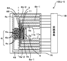
図29、図30は、変形例10の湿度センサ100Jの概略構成図である。この変形例10は、相変化物質6を導電性とし、相変化したときの相変化物質6の流動(粘性)の変化を電気的に検知することで、相変化物質6の相変化を検知するものである。図29は、回路基板1B側から、温度測定部5、相変化物質6、冷却部4を並列に配置した例であり、図30は、温度測定部5、相変化物質6、冷却部4を同心円状に配置した例である。
図29、図30に示すように、この変形例10の湿度センサ100Jにおいては、相変化物質6に一対の検出用リード線6a,6bが接続されている。
[Modification 10]
29 and 30 are schematic configuration diagrams of a humidity sensor 100J according to the tenth modification. This modification 10 detects the phase change of the phase change material 6 by making the phase change material 6 conductive and electrically detecting a change in flow (viscosity) of the phase change material 6 when the phase changes. Is. FIG. 29 shows an example in which the temperature measurement unit 5, the phase change material 6, and the cooling unit 4 are arranged in parallel from the circuit board 1B side. FIG. 30 shows the temperature measurement unit 5, the phase change material 6, and the cooling unit 4 arranged in parallel. It is the example arrange | positioned concentrically.
As shown in FIGS. 29 and 30, in the humidity sensor 100 </ b> J of the modified example 10, a pair of detection lead wires 6 a and 6 b are connected to the phase change material 6.

図31は、相変化したときの相変化物質6の流動(粘性)変化を電気的に検知するメカニズムについて説明する図である。同図では相変化物質6が固体から液体への相転移に伴う相変化物質6の流動(粘性)変化に伴う形状変化を説明している。この図では、加熱部11上に電気絶縁層3cを介在して、相変化物質6を積層している。
図(a)に示すように、相変化物質6が固体の状態のときは、相変化物質6は、検出用リード線6a,6bに接しており、導通している。加熱部11の発熱によって、固体の相変化物質6が既知の相転移温度になると、液化によって表面張力が発生し、同図の(b)に示すように中央へ凝集する。すると、相変化物質6が、各検出用リード6線6a,6bから離れ、その結果2つの検出用リード間の電気接続がOFFになる。このように、相変化物質6の導通状態を検出することで相変化物質6の相転移を検出できる。この場合、相変化物質6としては、表面張力が大きく、相変化物質6の下層との付着力が小さいものが好ましく、Snを用いるのが好適である。
FIG. 31 is a diagram for explaining a mechanism for electrically detecting a flow (viscosity) change of the phase change material 6 when the phase changes. In the figure, the phase change material 6 explains the shape change accompanying the flow (viscosity) change of the phase change material 6 accompanying the phase transition from solid to liquid. In this figure, the phase change material 6 is laminated on the heating unit 11 with the electrical insulating layer 3c interposed.
As shown in FIG. 5A, when the phase change material 6 is in a solid state, the phase change material 6 is in contact with the detection lead wires 6a and 6b and is conductive. When the solid phase change material 6 reaches a known phase transition temperature due to heat generated by the heating unit 11, surface tension is generated by liquefaction and aggregates to the center as shown in FIG. Then, the phase change material 6 is separated from each of the detection leads 6 wires 6a and 6b, and as a result, the electrical connection between the two detection leads is turned off. Thus, the phase transition of the phase change material 6 can be detected by detecting the conduction state of the phase change material 6. In this case, the phase change material 6 is preferably one having a large surface tension and a small adhesion to the lower layer of the phase change material 6, and it is preferable to use Sn.

また、次のようにして、検出用リード間の電気接続をONからOFFに切り替えることもできる。
図32(a)に示すように、相変化物質6が固体ときは、相変化物質6は2つの検出リード線間にまたがって連続して配置され、検出リード間の電気接続がONとなっている。そして、加熱部11の発熱によって、固体の相変化物質6が既知の相転移温度になり液化すると、同図の(b)に示すように液化によって流動し、各検出リード6a、6bに相変化物質6が凝集し、相変化物質6が分離して、検出リード線間の電気接続がOFFになる。よって、検出リード間の電気接続がOFFとなったときの温度が既知の相転移温度となる。相変化物質としては、表面張力が小さく、検出リード、相変化物質6の下層の電気絶縁層との濡れ性が大きい材質のものが好ましく、Inが適する。
Further, the electrical connection between the detection leads can be switched from ON to OFF as follows.
As shown in FIG. 32A, when the phase change material 6 is solid, the phase change material 6 is continuously arranged across the two detection lead wires, and the electrical connection between the detection leads is turned on. Yes. When the solid phase change material 6 becomes a known phase transition temperature and liquefies due to the heat generated by the heating unit 11, it flows by liquefaction as shown in FIG. 5B, and the phase change occurs in each of the detection leads 6a and 6b. The substance 6 aggregates and the phase change substance 6 separates, and the electrical connection between the detection leads is turned off. Therefore, the temperature when the electrical connection between the detection leads is turned off becomes a known phase transition temperature. The phase change material is preferably made of a material having a low surface tension and high wettability with the detection lead and the electrical insulating layer under the phase change material 6, and In is suitable.

上記では、相変化物質6の相変化によって、検出用リード6aと6b間の電気接続がOFFになることで、相変化物質の相転移を検知する場合について、説明したが、これとは逆に、相変化物質6の相変化によって、検出用リード6aと6b間の電気接続がOFFからONに切り替わる構成にすることもできる。   In the above, the case where the phase transition of the phase change material is detected by turning off the electrical connection between the detection leads 6a and 6b due to the phase change of the phase change material 6 has been described. The electrical connection between the detection leads 6a and 6b can be switched from OFF to ON by the phase change of the phase change material 6.

図33は、検出用リード6aと6b間の電気接続がOFFからONに切り替わる構成を説明する図である。
図(a)に示すように、相変化物質が固体のときは、電気絶縁層3c上の相変化物質は、2つの分離しており、相変化物質6は2つの検出リード6a,6b間にまたがって断続している。その結果、検出用リード6aと6bとの間の電気接続がOFFとなっている。加熱部11の発熱によって、固体の相変化物質6が既知の相転移温度になると、図の(b)に示すように液化によって流動し、電気絶縁層上の相変化物質6が一つとなり、相変化物質6は2つの検出リード6a,6b間にまたがって連続する。これにより、検出用リード6aと6bとの間の電気接続がOFFからONに切り替わり、相変化物質の相転移を検出することができる。この場合も、図32の構成と同様、相変化物質としては、表面張力が小さく、検出リード、相変化物質6の下層の電気絶縁層との濡れ性が大きい材質のものが好ましく、Inが適する。相変化物質6が冷えて、固化するときは、相変化物質6が収縮することにより、電気絶縁層3c上の相変化物質6は、再び2つの分離する。また、図31、図32の構成においては、一度、固体から液体に相変化してしまった後、再び、液体から固体に相変化物質6が相変化しても、始めの状態に戻って、検出用リード6aと6b間の電気接続がONとなることはないが、図33に示す構成においては、液体から固体に相変化物質6が相変化すると、始めの状態に戻るので、何度も温度キャリブレーションを行うことができる。
FIG. 33 is a diagram illustrating a configuration in which the electrical connection between the detection leads 6a and 6b is switched from OFF to ON.
As shown in FIG. 5A, when the phase change material is solid, the phase change material on the electrical insulating layer 3c is separated into two, and the phase change material 6 is located between the two detection leads 6a and 6b. It is intermittent across. As a result, the electrical connection between the detection leads 6a and 6b is OFF. When the solid phase change material 6 reaches a known phase transition temperature due to the heat generated by the heating unit 11, the solid phase change material 6 flows by liquefaction as shown in FIG. The phase change material 6 continues across the two detection leads 6a and 6b. Thereby, the electrical connection between the detection leads 6a and 6b is switched from OFF to ON, and the phase transition of the phase change substance can be detected. Also in this case, as in the configuration of FIG. 32, the phase change material is preferably made of a material having a low surface tension and high wettability with the detection lead and the electrical insulating layer under the phase change material 6, and In is suitable. . When the phase change material 6 cools and solidifies, the phase change material 6 contracts, so that the phase change material 6 on the electrical insulating layer 3c is separated into two again. Further, in the configuration of FIGS. 31 and 32, after the phase change from solid to liquid once, even if the phase change material 6 changes from liquid to solid again, it returns to the initial state, Although the electrical connection between the detection leads 6a and 6b is not turned on, in the configuration shown in FIG. 33, when the phase change material 6 changes from a liquid to a solid, it returns to the initial state, so Temperature calibration can be performed.

また、変形例10のように、相変化物質6が固体から液体に相転移することによる流動性(粘性)の変化を電気的に検知することで、相変化を検知する場合、相変化物質6を電気絶縁層で覆ってしまうと、相変化物質6の流動性を阻害して、流動変形しないおそれがある。よって、図31〜図33の構成を採用する場合は、相変化物質6は電気絶縁層を被覆せず露出させる。また、この変形例の場合は、相変化物質6の量を少なくして、相変化物質6がすばやく相転移温度にまで加熱されるようにするのが好ましい。   In addition, when the phase change is detected by electrically detecting the change in fluidity (viscosity) due to the phase transition of the phase change material 6 from solid to liquid as in the modification 10, the phase change material 6 If it is covered with an electrical insulating layer, the fluidity of the phase change material 6 is hindered, and there is a possibility that it will not flow and deform. Therefore, when the configurations of FIGS. 31 to 33 are employed, the phase change material 6 is exposed without covering the electrical insulating layer. In the case of this modification, it is preferable to reduce the amount of the phase change material 6 so that the phase change material 6 is quickly heated to the phase transition temperature.

図34は、変形例10の湿度センサ100Jにおける温度キャリブレーション、温度、露点検出と湿度出力の入出力信号のタイミングチャートであり、図35は、フローチャートである。以下の説明では、相変化物質6の構成は、図31、図32に示すように、相変化物質が固体のときは、検出用リード線間の電機接続がON状態であり、固体から液体に相変化すると、検出用リード線間の電気接続がOFFになるものを例に挙げて、説明する。
温度キャリブレーションが実行されると、加熱電源から温度測定部5に加熱電流を供給して、相変化物質6が加熱されるとともに、相変化物質6に相変化検出用電流を供給し、相変化物質に印加された電圧(以下、相変化電圧という)を監視する。相変化物質6が固定から液体に相変化すると、先の図31(b)や図32(b)に示すように、検出用リード線間の電気接続が切れる。その結果、相変化電流が0(未検知)となり、相変化物質6が相変化したことを検知することができる。このようにして、相変化物質6の相変化が検知されたら、上述と同様にして、そのときの温度測定部の電気抵抗値と、相変化物質6の既知の相転移温度に基づいて、温度依存性の関数を補正する。その後の雰囲気温度の測定、露点の測定、湿度の算出は、上述と同じである。
FIG. 34 is a timing chart of input / output signals of temperature calibration, temperature / dew point detection, and humidity output in the humidity sensor 100J of the modified example 10, and FIG. 35 is a flowchart. In the following description, as shown in FIGS. 31 and 32, the phase change material 6 is configured such that when the phase change material is a solid, the electrical connection between the detection lead wires is in an ON state, and the liquid is changed from a solid to a liquid. An example will be described in which the electrical connection between the detection lead wires is turned off when the phase changes.
When the temperature calibration is executed, a heating current is supplied from the heating power source to the temperature measuring unit 5 to heat the phase change material 6 and a phase change detection current is supplied to the phase change material 6 to change the phase. The voltage applied to the substance (hereinafter referred to as phase change voltage) is monitored. When the phase change material 6 changes phase from fixed to liquid, the electrical connection between the detection lead wires is cut as shown in FIGS. 31 (b) and 32 (b). As a result, the phase change current becomes 0 (not detected), and it can be detected that the phase change material 6 has changed phase. Thus, when the phase change of the phase change material 6 is detected, in the same manner as described above, based on the electrical resistance value of the temperature measurement unit at that time and the known phase transition temperature of the phase change material 6, the temperature Correct the dependency function. Subsequent measurement of ambient temperature, measurement of dew point, and calculation of humidity are the same as described above.

図36は、変形例10の湿度センサ100Jにおいて、冷却部4の冷却電極4aで、相変化物質6を加熱する場合の温度キャリブレーション、温度、露点検出と湿度出力の入出力信号のタイミングチャートであり、図37は、フローチャートである。図に示すように、この場合は、温度キャリブレーションが実行されると、加熱電源から冷却部4に加熱電流が供給され、相変化物質6が加熱される。この加熱電流は、冷却時とは逆向きに流れる電流である。また、温度測定部5に温度検出用電流が供給され、相変化物質6に相変化検出用電流が供給される。その後は、上記した説明と同様、相変化電流が0(未検知)となったときの、温度測定部5の抵抗値を算出し、温度測定部5の抵抗値と、既知の相転移温度から、温度依存性を示す関数を補正する。その後の、補正された温度依存性の関数を用いて、雰囲気温度の測定、露点の測定、湿度の算出を行う。   FIG. 36 is a timing chart of input / output signals of temperature calibration, temperature and dew point detection, and humidity output when the phase change material 6 is heated by the cooling electrode 4a of the cooling unit 4 in the humidity sensor 100J of the modification 10. FIG. 37 is a flowchart. As shown in the figure, in this case, when temperature calibration is executed, a heating current is supplied from the heating power source to the cooling unit 4 and the phase change material 6 is heated. This heating current is a current that flows in the opposite direction to that during cooling. Further, a temperature detection current is supplied to the temperature measurement unit 5, and a phase change detection current is supplied to the phase change material 6. Thereafter, similarly to the above description, the resistance value of the temperature measurement unit 5 when the phase change current becomes 0 (undetected) is calculated, and the resistance value of the temperature measurement unit 5 and the known phase transition temperature are calculated. The function indicating temperature dependence is corrected. Then, using the corrected function of temperature dependence, the ambient temperature is measured, the dew point is measured, and the humidity is calculated.

[変形例10−1]
図38、図39は、変形例10の湿度センサ100Jにおいて、温度測定部5とは、別に、加熱部11を設けたものである。図38は、各部を平行に配置した構成の変形例10の湿度センサ100J−3の概略構成図であり、図39は、同心円状に配置した構成の変形例10の湿度センサ100J−4の概略構成図である。加熱部11は、温度測定部5と相変化物質6との間に配置した。
[Modification 10-1]
38 and 39 show a humidity sensor 100J according to Modification 10 in which a heating unit 11 is provided separately from the temperature measurement unit 5. FIG. 38 is a schematic configuration diagram of the humidity sensor 100J-3 according to the modified example 10 in which the respective parts are arranged in parallel, and FIG. 39 is a schematic diagram of the humidity sensor 100J-4 according to the modified example 10 that is arranged concentrically. It is a block diagram. The heating unit 11 was disposed between the temperature measurement unit 5 and the phase change material 6.

また、図39に示すように、同心円状に各部を配置する構成においては、良好な露点検出を行うためには、温度測定部5周辺を円周に沿って均一な温度分布にする必要がある。そのため、冷却部4の冷却電極4aを、温度測定部5のリード線との接続部付近にも設けておく必要がある。しかしながら、この場合、冷却部4よりも内側に配置された加熱部11に接続する一対のリード線11a,11bが、冷却電極4aと干渉するため、真直ぐに延設させることができない。そこで、加熱部11に接続するリード線11a,11bと冷却電極4aとを電気絶縁層3aを介して積層させることも考えられる。しかしながら、このようにすると、この積層部分の熱容量が大きくなって、温度測定部5周辺を円周に沿って均一な温度分布にすることができない。そこで、加熱部11のリード線11a,11bを、温度測定部5のリード線5a,5bと180°位相がずれた位置に配置した。また、このようにした場合、加熱部11のリード線11a,11bに対して、図中上側の冷却部4と図中下側の冷却部4とを直列接続しようとすると、冷却部4同士を接続する線と、加熱部11のリード線11a,11bとを電気絶縁層3aを介して交差させる必要が生じ、上述同様、その部分の熱容量が大きくなってしまう。そこで、冷却部4を図中上側と下側とで電気的分ける。これにより、リード線11aが多い構成でも、これら配線リードを交差させることなく、各部を回路基板1Bに接続することができる。よって、温度測定部5周辺を円周に沿って均一な温度分布させることができ、また、配線リード間の電気絶縁性を高め、製造工程を簡単にすることができる。   Further, as shown in FIG. 39, in the configuration in which the respective parts are arranged concentrically, in order to perform good dew point detection, it is necessary to make the temperature measurement part 5 periphery a uniform temperature distribution along the circumference. . Therefore, it is necessary to provide the cooling electrode 4 a of the cooling unit 4 also in the vicinity of the connection portion with the lead wire of the temperature measuring unit 5. However, in this case, since the pair of lead wires 11a and 11b connected to the heating unit 11 disposed on the inner side of the cooling unit 4 interfere with the cooling electrode 4a, it cannot be extended straight. Therefore, it is also conceivable to laminate the lead wires 11a and 11b connected to the heating unit 11 and the cooling electrode 4a via the electric insulating layer 3a. However, if this is done, the heat capacity of this laminated portion becomes large, and the temperature measurement unit 5 and its periphery cannot be made to have a uniform temperature distribution along the circumference. Therefore, the lead wires 11a and 11b of the heating unit 11 are disposed at positions that are 180 ° out of phase with the lead wires 5a and 5b of the temperature measurement unit 5. In addition, in this case, when the cooling unit 4 on the upper side in the figure and the cooling unit 4 on the lower side in the figure are to be connected in series to the lead wires 11a and 11b of the heating unit 11, the cooling units 4 are connected to each other. It is necessary to cross the connecting wire and the lead wires 11a and 11b of the heating unit 11 via the electric insulating layer 3a, and the heat capacity of the portion becomes large as described above. Therefore, the cooling unit 4 is electrically divided into an upper side and a lower side in the figure. Thereby, even in a configuration with many lead wires 11a, each part can be connected to the circuit board 1B without crossing these wiring leads. Therefore, the temperature measurement part 5 periphery can be made to distribute temperature uniformly along a periphery, and the electrical insulation between wiring leads can be improved, and a manufacturing process can be simplified.

図40は、変形例10−1の湿度センサにおける温度キャリブレーション、温度、露点検出と湿度出力の入出力信号のタイミングチャートであり、図41は、フローチャートである。図に示すように、この場合は、温度キャリブレーションが実行されると、加熱電源から加熱部11に加熱電流が供給され、相変化物質6が加熱される。また、温度測定部5に温度検出用電流が供給され、相変化物質6に相変化検出用電流が供給される。その後は、上記した説明と同様、相変化電流が0(未検知)となったときの、温度測定部5の抵抗値を算出し、温度測定部5の抵抗値と、既知の相転移温度から、温度依存性を示す関数を補正する。その後の、補正された温度依存性の関数を用いて、雰囲気温度の測定、露点の測定、湿度の算出を行う。   FIG. 40 is a timing chart of input / output signals of temperature calibration, temperature and dew point detection, and humidity output in the humidity sensor of Modification 10-1, and FIG. 41 is a flowchart. As shown in the figure, in this case, when the temperature calibration is performed, a heating current is supplied from the heating power source to the heating unit 11 and the phase change material 6 is heated. Further, a temperature detection current is supplied to the temperature measurement unit 5, and a phase change detection current is supplied to the phase change material 6. Thereafter, similarly to the above description, the resistance value of the temperature measurement unit 5 when the phase change current becomes 0 (undetected) is calculated, and the resistance value of the temperature measurement unit 5 and the known phase transition temperature are calculated. The function indicating temperature dependence is corrected. Then, using the corrected function of temperature dependence, the ambient temperature is measured, the dew point is measured, and the humidity is calculated.

[変形例10−2]
図42は、変形例10の湿度センサ100J−5の相変化物質6を複数備えた構成を示す概略平面図である。図42に示すように、各相変化物質それぞれに検出用リード線が接続されている。
[Modification 10-2]
FIG. 42 is a schematic plan view showing a configuration including a plurality of phase change substances 6 of the humidity sensor 100J-5 of the modification 10. As shown in FIG. 42, a detection lead wire is connected to each phase change substance.

図43は、変形例10−2の湿度センサ100J−5における温度キャリブレーション、温度、露点検出と湿度出力の入出力信号のタイミングチャートである。
図に示すように、温度キャリブレーションが実行されると、加熱部11に加熱電流が供給され、温度測定部5に温度検出用電流が供給される。また、各相変化物質6A,6Bに相変化検出電流が供給される。回路基板1Bの不図示の制御回路は、各相変化物質6A,6Bよりも下流の相変化電流を監視する。そして、相変化物質6Aが相変化すると、相変化物質6Aに供給される相変化電流が検出されなくなり、相変化物質Aが相変化したことを検知することができ、そのときの温度測定部5の抵抗値を算出し、メモリに記憶しておく。さらに加熱部11で加熱していくと、相変化物質6Bが相変化して、相変化電流が検出されなくなる。その結果、相変化物質6Bが、相転移したことを検知することができる。そのときの温度測定部5の抵抗値を求める。そして、メモリに記憶した相変化物質6Aが相転移したときの温度測定部5の抵抗値と、相変化物質6Aの既知の相転移温度と、相変化物質6Bが相転移したときの温度測定部5の抵抗値と、相変化物質6Bの既知の相転移温度とから、温度依存性の関数を算出して、温度キャリブレーションが終了する。
FIG. 43 is a timing chart of input / output signals of temperature calibration, temperature / dew point detection, and humidity output in the humidity sensor 100J-5 of Modification 10-2.
As shown in the figure, when the temperature calibration is performed, a heating current is supplied to the heating unit 11, and a temperature detection current is supplied to the temperature measurement unit 5. Further, a phase change detection current is supplied to each of the phase change materials 6A and 6B. A control circuit (not shown) of the circuit board 1B monitors a phase change current downstream of the phase change materials 6A and 6B. When the phase change material 6A undergoes a phase change, the phase change current supplied to the phase change material 6A can no longer be detected, and it can be detected that the phase change material A has undergone a phase change. Is calculated and stored in the memory. When the heating unit 11 further heats up, the phase change material 6B undergoes a phase change and the phase change current is not detected. As a result, it can be detected that the phase change material 6B has undergone phase transition. The resistance value of the temperature measurement unit 5 at that time is obtained. The resistance value of the temperature measuring unit 5 when the phase change material 6A stored in the memory undergoes a phase transition, the known phase transition temperature of the phase change material 6A, and the temperature measuring unit when the phase change material 6B undergoes phase transition. 5 is calculated from the resistance value of 5 and the known phase transition temperature of the phase change material 6B, and the temperature calibration is completed.

次に、所定のタイミングで、求めた温度依存性の関数を用いて、雰囲気温度と、露点を求めて、湿度を算出する。   Next, at a predetermined timing, the atmospheric temperature and the dew point are obtained by using the obtained temperature dependency function, and the humidity is calculated.

[変形例11]
次に、相変化物質の相転移を、電気伝導度の変化で検出する変形例11の湿度センサ100Kについて、説明する。
この変形例11の湿度センサ100Kの基本構成は、先の図29、図30、図38、図39、図42と同様な構成である。電気伝導度の変化で検出する場合、相変化物質としては、上述したように、CTRサ−ミスタにも用いられているVやチタン酸バリウムを主成分とするPTCサ−ミスタを、好適に用いることができる。
[Modification 11]
Next, a description will be given of a humidity sensor 100K of Modification 11 that detects a phase transition of a phase change material by a change in electrical conductivity.
The basic configuration of the humidity sensor 100K according to Modification 11 is the same as that shown in FIGS. 29, 30, 38, 39, and 42. When detecting by a change in electrical conductivity, as described above, as a phase change material, a PTC thermistor mainly composed of V 2 O 5 or barium titanate, which is also used in a CTR thermistor, It can be used suitably.

図44は、変形例11の湿度センサ100Kの制御ブロック図である。
図に示すように、変形例11の湿度センサ100Kの回路領域1bには、相変化物質6に、相変化検出用電流を供給するための相変化電源116と、相変化物質への電流値と、電圧値とから相変化物質6の抵抗値を算出するための相変化抵抗値算出部117とを備えている。後の構成は、先の図4と同じ構成であるので、説明を省く。
FIG. 44 is a control block diagram of the humidity sensor 100K according to the eleventh modification.
As shown in the figure, in the circuit region 1b of the humidity sensor 100K of the modification 11, a phase change power source 116 for supplying a phase change detection current to the phase change material 6, a current value to the phase change material, and And a phase change resistance value calculation unit 117 for calculating the resistance value of the phase change material 6 from the voltage value. The subsequent configuration is the same as that shown in FIG. 4 and will not be described.

CPU113から、温度キャリブレーション信号を受信したら、回路領域1bは、加熱電源103から加熱部11に加熱電流を供給する。また、温度検出電源104を制御して、温度測定部5に温度検出用電流を供給する。また、相変化電源116を制御して、相変化物質に相変化検出用電流を供給する。相変化物質が相転移すると、抵抗が急激に変化する。よって、回路領域1bでは、相変化物質6Aの抵抗値の時間微分値ΔRを監視し、この値が急激に増加したら、相変化したと検知することができる。相変化物質6の相変化を検知したら、回路領域1bは、抵抗値算出部112で温度測定部5の抵抗値を算出する。そして、メモリに格納されている相変化物質6の既知の相転移温度と算出した温度測定部5の抵抗値とから、温度依存性を示す関数を演算部107で補正することで、温度キャリブレーションが行われる。   When the temperature calibration signal is received from the CPU 113, the circuit region 1 b supplies a heating current from the heating power supply 103 to the heating unit 11. Further, the temperature detection power source 104 is controlled to supply a temperature detection current to the temperature measurement unit 5. The phase change power supply 116 is controlled to supply a phase change detection current to the phase change material. When the phase change material undergoes a phase transition, the resistance changes rapidly. Therefore, in the circuit region 1b, the time differential value ΔR of the resistance value of the phase change material 6A is monitored, and if this value increases rapidly, it can be detected that the phase has changed. When the phase change of the phase change material 6 is detected, the resistance value calculation unit 112 calculates the resistance value of the temperature measurement unit 5 in the circuit region 1 b. Then, the temperature calibration is performed by correcting a function indicating the temperature dependence from the known phase transition temperature of the phase change material 6 stored in the memory and the calculated resistance value of the temperature measurement unit 5 by the calculation unit 107. Is done.

そして、所定のタイミングでCPU113から湿度検出信号を受信すると、温度測定部5に温度検出用電流を供給し、抵抗値算出部112で抵抗値を算出し、比較部108で、温度キャリブレーションによって補正した温度依存性の関数を用いて、雰囲気温度が求められ、出力される。次に、冷却電源105を制御して、冷却部4に冷却用電流が供給され、観測面8が冷却される。観測面8に結露が生じたことをフォトカプラ7で検知したら、そのときの温度測定部5の抵抗値を算出し、温度依存性の関数を用いて、露点が求められる。そして、先ほど出力した雰囲気温度と、露点と、先に示した式(1)、(2)とを用いて、湿度演算部110で湿度が算出され、出力される。   When a humidity detection signal is received from the CPU 113 at a predetermined timing, a temperature detection current is supplied to the temperature measurement unit 5, a resistance value is calculated by the resistance value calculation unit 112, and the comparison unit 108 corrects it by temperature calibration. The ambient temperature is obtained and output using the temperature dependency function. Next, the cooling power source 105 is controlled, a cooling current is supplied to the cooling unit 4, and the observation surface 8 is cooled. When the photocoupler 7 detects that dew condensation has occurred on the observation surface 8, the resistance value of the temperature measuring unit 5 at that time is calculated, and the dew point is obtained using a temperature-dependent function. Then, the humidity calculation unit 110 calculates and outputs the humidity using the ambient temperature, the dew point, and the equations (1) and (2) shown above.

また、変形例11の湿度センサ100Kにおいては、図45や、図46に示すように、複数の相変化物質6A,6Bを、電気的に並列接続することができる。   Moreover, in the humidity sensor 100K of the modified example 11, as shown in FIG. 45 and FIG. 46, a plurality of phase change substances 6A and 6B can be electrically connected in parallel.

[変形例12]
次に、相変化物質6の相転移を、相変化物質の誘電率の変化で検出する変形例12の湿度センサ100Lについて、説明する。
この変形例12の湿度センサ100Lの基本構成も、先の図29、図30、図38、図39、図42と同様な構成である。
[Modification 12]
Next, the humidity sensor 100L of Modification 12 that detects the phase transition of the phase change material 6 by the change in the dielectric constant of the phase change material will be described.
The basic configuration of the humidity sensor 100L according to the modified example 12 is the same as that shown in FIGS. 29, 30, 38, 39, and 42.

図47は、変形例12の湿度センサ100Lの断面図である。図に示すように相変化物質6が相転移するときの誘電率の変化を検出する場合、相変化物質6を挟んで対向電極61を設ける。対向電極61の一方は、検出用リード線6aに接続されており、他方は検出用リード線6bに接続されている。相変化物質としては、タンタル酸ニオブ酸カリウム(KTa1−xNbxO3)を好適に用いることができる。   FIG. 47 is a cross-sectional view of a humidity sensor 100L of Modification 12. As shown in the figure, when detecting a change in dielectric constant when the phase change material 6 undergoes a phase transition, a counter electrode 61 is provided with the phase change material 6 interposed therebetween. One of the counter electrodes 61 is connected to the detection lead 6a, and the other is connected to the detection lead 6b. As the phase change material, potassium tantalate niobate (KTa1-xNbxO3) can be preferably used.

温度キャリブレーションが実行されると、相変化物質6に直流電圧を印加する。相変化物質6が相転移して、相変化物質6の誘電率が変化すると、検出用リードに電流が流れるので、回路基板1Bで、検出用リード線に電流が流れたことを検知したら、相変化物質6が相変化したことを検知することができる。   When the temperature calibration is executed, a DC voltage is applied to the phase change material 6. When the phase change material 6 undergoes phase transition and the dielectric constant of the phase change material 6 changes, a current flows through the detection lead. Therefore, when the circuit board 1B detects that a current flows through the detection lead, It can be detected that the change substance 6 has undergone a phase change.

[変形例13]
次に、圧電体たる圧電材料を用いて、相変化物質の相変化を検知する変形例13の湿度センサ100Mについて、説明する。圧電材料を用いることによって、相変化物質6の固有振動数の変化、体積変化、剛性変化から、相変化物質6の相変化を検出することが可能となる。変形例13の湿度センサ100Mの基本構成は、先の図29、図30、図38、図39、図42と同様な構成である。
[Modification 13]
Next, a humidity sensor 100M of Modification 13 that detects a phase change of a phase change material using a piezoelectric material that is a piezoelectric body will be described. By using the piezoelectric material, the phase change of the phase change material 6 can be detected from the change in natural frequency, volume change, and stiffness change of the phase change material 6. The basic configuration of the humidity sensor 100M according to the modification 13 is the same as that shown in FIGS. 29, 30, 38, 39, and 42.

図48は、変形例13の湿度センサ100Mの断面図である。
図に示すように圧電効果を有するPZT等の圧電材料層62の上に相変化物質6が設けられている。圧電材料層62には、検出用リード線6a,6bが、接続されている。
FIG. 48 is a cross-sectional view of a humidity sensor 100M of Modification 13.
As shown in the figure, a phase change material 6 is provided on a piezoelectric material layer 62 such as PZT having a piezoelectric effect. Detection lead wires 6 a and 6 b are connected to the piezoelectric material layer 62.

図49は、変形例13の湿度センサ100Mの制御ブロック図である。
圧電材料を用いて、相変化物質6の相変化を検知する変形例13の湿度センサ100Mにおいては、圧電材料層62に交流電圧を印加するための発振電源121や、圧電材料層62からの電圧や交流電圧を検知する検波・電圧検知部122を備えている。
FIG. 49 is a control block diagram of the humidity sensor 100M of Modification 13.
In the humidity sensor 100M according to the modified example 13 that detects the phase change of the phase change material 6 using a piezoelectric material, the oscillation power supply 121 for applying an AC voltage to the piezoelectric material layer 62 and the voltage from the piezoelectric material layer 62 are used. And a detector / voltage detector 122 for detecting AC voltage.

まず、圧電材料を用いた相変化物質6の固有振動数変化の検知について、説明する。周期的力の周波数を試料に加え、その応答を測定する方法、すなわちメカニカルスペクトロスコピー(動的粘弾性測定:DMA)を適用することで、相変化物質6の相変化に伴う固有振動数変化を検出することができる。具体的には、圧電材料層62に交流電圧を印加して、圧電材料層62を所定の周波数で振動させる。例えば、相変化物質6が相変化して固有振動数が変化しとき、相変化物質6が圧電材料層62の振動に共振するような周波数で、圧電材料層62を振動させる。このように、圧電材料層62を振動させることにより、圧電材料層62上の相変化物質6が振動し、圧電材料層62に対して、相変化物質から応力が加わり、圧電材料層62から所定の交流波が出力される。相変化物質6が相転移して、固有振動数が変化すると、相変化物質6が、圧電材料層62の振動に共振して、大きく振動する。その結果、相変化物質6から圧電材料層62に加わる力が増加し、圧電材料層62から出力される交流波の振幅が増大する。回路領域1bでは、圧電材料層62から出力された交流波の振幅(電圧)の時間微分値ΔVを監視し、時間微分値ΔVが0でない値をとったら、相変化物質6が相変化したことを検知することができる。上記では、相変化物質6の相変化によって、相変化物質6が圧電材料層62の振動に共振させているが、これとは逆に、相変化前の相変化物質6が、圧電材料層62の振動に共振するよう、圧電材料層62を振動させてもよい。また、図48に示すように、相変化物質6や圧電材料層62は、基板1の空洞部20上に設けているので、圧電材料層62が振動しやすく、高感度で相転移を検出することができる。   First, detection of the natural frequency change of the phase change material 6 using a piezoelectric material will be described. By applying a frequency of periodic force to the sample and measuring its response, that is, mechanical spectroscopy (dynamic viscoelasticity measurement: DMA), the natural frequency change accompanying the phase change of the phase change material 6 can be reduced. Can be detected. Specifically, an AC voltage is applied to the piezoelectric material layer 62 to vibrate the piezoelectric material layer 62 at a predetermined frequency. For example, when the phase change material 6 undergoes a phase change and the natural frequency changes, the piezoelectric material layer 62 is vibrated at a frequency such that the phase change material 6 resonates with the vibration of the piezoelectric material layer 62. In this way, by vibrating the piezoelectric material layer 62, the phase change material 6 on the piezoelectric material layer 62 vibrates, and stress is applied to the piezoelectric material layer 62 from the phase change material. AC wave is output. When the phase change material 6 undergoes phase transition and the natural frequency changes, the phase change material 6 resonates with the vibration of the piezoelectric material layer 62 and vibrates greatly. As a result, the force applied to the piezoelectric material layer 62 from the phase change material 6 increases, and the amplitude of the AC wave output from the piezoelectric material layer 62 increases. In the circuit region 1b, the time differential value ΔV of the amplitude (voltage) of the AC wave output from the piezoelectric material layer 62 is monitored, and if the time differential value ΔV takes a non-zero value, the phase change material 6 has undergone a phase change. Can be detected. In the above description, the phase change material 6 is caused to resonate with the vibration of the piezoelectric material layer 62 due to the phase change of the phase change material 6. On the contrary, the phase change material 6 before the phase change is the piezoelectric material layer 62. The piezoelectric material layer 62 may be vibrated so as to resonate with this vibration. Further, as shown in FIG. 48, since the phase change material 6 and the piezoelectric material layer 62 are provided on the cavity 20 of the substrate 1, the piezoelectric material layer 62 easily vibrates and detects a phase transition with high sensitivity. be able to.

次に、圧電材料を用いた相変化物質6の体積変化や剛性変化の検知について説明する。これは、相変化物質6から圧電材料層62に加わる機械的な応力による圧電材料層62の抵抗変化である所謂ピエゾ抵抗効果を用いて、相変化物質6の体積変化や剛性変化を検知するものである。具体的には、圧電材料層62に検知用の電流を印加する。相変化物質6が加熱されて、固体から液体に相変化すると、電気絶縁層3aに覆われている相変化物質6の体積が増加する。これにより、相変化物質6の圧電材料層62に対する応力が増加し、圧電材料層62の抵抗値が変化する。よって、回路領域1bにおいて、電圧変化や、圧電材料層62の抵抗値変化を検知することにより、相変化物質6の相変化を検知することができる。一方、相変化物質6の剛性変化を検知する場合は、相変化物質6が固体から液体に相変化すると、相変化物質6の剛性が低下し、圧電材料層62に加わる応力が低下する。その結果、圧電材料層62の抵抗値が変化するので、回路領域1bにおいて、電圧変化や、圧電材料層62の抵抗値変化を検知することにより、相変化物質の相変化を検知することができる。   Next, detection of volume change and stiffness change of the phase change material 6 using a piezoelectric material will be described. This is to detect a volume change or a rigidity change of the phase change material 6 by using a so-called piezoresistance effect which is a resistance change of the piezoelectric material layer 62 due to a mechanical stress applied to the piezoelectric material layer 62 from the phase change material 6. It is. Specifically, a detection current is applied to the piezoelectric material layer 62. When the phase change material 6 is heated to change the phase from solid to liquid, the volume of the phase change material 6 covered by the electrical insulating layer 3a increases. Thereby, the stress with respect to the piezoelectric material layer 62 of the phase change substance 6 increases, and the resistance value of the piezoelectric material layer 62 changes. Therefore, the phase change of the phase change material 6 can be detected by detecting a voltage change or a resistance value change of the piezoelectric material layer 62 in the circuit region 1b. On the other hand, when detecting a change in the rigidity of the phase change material 6, when the phase change material 6 changes from a solid to a liquid, the rigidity of the phase change material 6 decreases and the stress applied to the piezoelectric material layer 62 decreases. As a result, since the resistance value of the piezoelectric material layer 62 changes, the phase change of the phase change substance can be detected by detecting the voltage change or the resistance value change of the piezoelectric material layer 62 in the circuit region 1b. .

[変形例14]
次に、相変化物質6の光学的変化で、相変化物質の相変化を検出する変形例14の湿度センサ100Nについて説明する。この場合、相変化物質6として、相変化物質6が相変化したとき、透過特性、反射特性、吸収特性等の光学特性が変化する物質を用いる。例えば、酸化バナジウムのサーモクロミック調光物質は、調光温度を元素添加などにより必要に応じて室温付近に精密に設定することができ、好適である。また、液晶相と液体相とで光学的特性が異なるサーモトロピック液晶であって相転移温度が40℃から50℃のMBBA(Methoxy benziliden p−butyl aniline)も好適に用いることができる。また、相転移温度にて結晶の構造相転移を生じ、二次電気光学定数(Kerr定数)が変化するタンタル酸ニオブ酸カリウム(KTa1−xNbxO3)も好適に用いることができる。上記酸化バナジウムのサーモクロミック調光物質は、調光温度を元素添加などにより必要に応じて室温付近に精密に設定することができる。
[Modification 14]
Next, a description will be given of the humidity sensor 100N according to the modified example 14 that detects the phase change of the phase change material by the optical change of the phase change material 6. In this case, as the phase change material 6, a material that changes optical characteristics such as transmission characteristics, reflection characteristics, and absorption characteristics when the phase change material 6 undergoes a phase change is used. For example, a thermochromic light-modulating substance of vanadium oxide is suitable because the light-modulating temperature can be precisely set around room temperature as required by adding elements. In addition, MBBA (Methoxy benzylid p-butyline), which is a thermotropic liquid crystal having different optical characteristics between a liquid crystal phase and a liquid phase and has a phase transition temperature of 40 ° C. to 50 ° C., can also be suitably used. Further, potassium tantalate niobate (KTa1-xNbxO3), which causes a structural phase transition of the crystal at the phase transition temperature and changes the second-order electro-optic constant (Kerr constant), can also be suitably used. In the vanadium oxide thermochromic light-modulating substance, the light-modulating temperature can be precisely set around room temperature as required by adding elements.

図50は、変形例14の湿度センサ100Nの制御ブロック図である。図50に示すように、この変形例14の湿度センサ100Nは、観測面8に凝集が生じたか否を検知するフォトカプラ7を用いて、相変化物質6の相変化を光学的検知する。   FIG. 50 is a control block diagram of the humidity sensor 100N of the modification 14. As shown in FIG. 50, the humidity sensor 100N of the modified example 14 optically detects the phase change of the phase change material 6 by using a photocoupler 7 that detects whether or not the observation surface 8 is aggregated.

図51は、変形例6の湿度センサ100Fと同一構成の断面図である。図51の点線に示すように、発光部7aから出射された光の一部は、空洞部20の冷却部側の壁面200aに反射して相変化部に入射する。そして、相変化物質6から反射した光は、加熱部側壁面200bに反射して、受光部7bに入射する。よって、相変化物質6が相転移して、光学特性が変化すると、受光部7に入射する光量が変化する。よって、受光部7bの出力により相変化物質6の相転移を検知することができる。   FIG. 51 is a cross-sectional view of the same configuration as the humidity sensor 100F of the sixth modification. As shown by the dotted line in FIG. 51, a part of the light emitted from the light emitting part 7a is reflected by the wall surface 200a on the cooling part side of the cavity part 20 and enters the phase change part. The light reflected from the phase change material 6 is reflected by the heating unit side wall surface 200b and enters the light receiving unit 7b. Therefore, when the phase change material 6 undergoes phase transition and the optical characteristics change, the amount of light incident on the light receiving unit 7 changes. Therefore, the phase transition of the phase change material 6 can be detected by the output of the light receiving unit 7b.

図52は、変形例14の湿度センサ100Nの温度キャリブレーション、温度、露点検出と湿度出力の入出力信号のタイミングチャートであり、図53は、フローチャートである。
温度キャリブレーションが実行されると、フォトカプラ7の発光部7aに電圧を印加する。図51に示したように、発光部7aから出射された光は、相変化物質6に入射し、相変化物質から反射した光が、受光部7bに入射する。相変化物質6の相変化が生じておらず、相変化物質6が鏡面状態のときは、フォトカプラ7の受光部は、電圧V0を出力している。相変化物質6が相変化すると、光学特性が変化し、相変化物質6に入射した光が散乱する。その結果、受光部7bに入射する光量が低下する。回路領域(回路基板側)では、受光部7bの出力電圧の時間微分値を監視し、時間微分値が0以外の値をとったとき、相変化物質が相変化したことを検知することができる。フォトカプラ7で相変化物質6の相変化を検知したら、そのときの温度測定部5の抵抗値を算出し、既知の相転移温度を算出した抵抗値を用いて、温度依存性を示す関数を補正する。その後の湿度の測定は、上述と同様である。
FIG. 52 is a timing chart of input / output signals of temperature calibration, temperature / dew point detection, and humidity output of the humidity sensor 100N of the modified example 14, and FIG. 53 is a flowchart.
When the temperature calibration is executed, a voltage is applied to the light emitting unit 7a of the photocoupler 7. As shown in FIG. 51, the light emitted from the light emitting unit 7a enters the phase change material 6, and the light reflected from the phase change material enters the light receiving unit 7b. When the phase change of the phase change material 6 does not occur and the phase change material 6 is in a mirror state, the light receiving unit of the photocoupler 7 outputs the voltage V0. When the phase change material 6 undergoes a phase change, the optical characteristics change, and light incident on the phase change material 6 is scattered. As a result, the amount of light incident on the light receiving unit 7b decreases. In the circuit area (circuit board side), the time differential value of the output voltage of the light receiving unit 7b is monitored, and when the time differential value takes a value other than 0, it can be detected that the phase change material has changed phase. . When the phase change of the phase change material 6 is detected by the photocoupler 7, the resistance value of the temperature measuring unit 5 at that time is calculated, and a function indicating temperature dependence is calculated using the resistance value obtained by calculating the known phase transition temperature. to correct. The subsequent measurement of humidity is the same as described above.

また、例えば、図54に示すように、相変化物質6を、冷却電極4aと交互に配置したり、図55や図56に示すように、相変化物質6と冷却電極4aとを積層させたりしてもよい。   Further, for example, as shown in FIG. 54, the phase change material 6 is alternately arranged with the cooling electrode 4a, or the phase change material 6 and the cooling electrode 4a are laminated as shown in FIG. 55 and FIG. May be.

次に、凝集検出手段としてのフォトカプラ7の変形例について、説明する。   Next, a modification of the photocoupler 7 as the aggregation detection means will be described.

[変形例15]
図57は、変形例15の湿度センサ100Oの概略構成図であり、(a)は、平面図であり、(b)は、(a)のC−C断面図である。図に示すように、この変形例15は、フォトカプラ7を、冷却部4、相変化物質6、温度測定部5が設けられた検知基板のおもて面電気絶縁層3aに設けたものである。
図に示すように、環状の冷却部4、温度測定部5および相変化物質6などの中心にフォトカプラ7の発光部7が設けられている。フォトカプラ7の複数の受光部7bは、放熱電極4bよりも内側(冷却電極4側)で、放熱電極4bの間にそれぞれ配置されている。このように配置することで、図29に示す環状空洞部20を、放熱電極4bまで延設させずに済み、放熱電極4bの熱をベース材2に逃すことができる。
[Modification 15]
FIGS. 57A and 57B are schematic configuration diagrams of a humidity sensor 100O according to the modified example 15. FIG. 57A is a plan view, and FIG. 57B is a cross-sectional view taken along the line CC in FIG. As shown in the figure, in this modified example 15, the photocoupler 7 is provided on the front surface electrical insulating layer 3a of the detection substrate provided with the cooling unit 4, the phase change material 6, and the temperature measuring unit 5. is there.
As shown in the figure, a light emitting unit 7 of a photocoupler 7 is provided at the center of an annular cooling unit 4, a temperature measuring unit 5, a phase change material 6, and the like. The plurality of light receiving portions 7b of the photocoupler 7 are respectively arranged between the heat radiation electrodes 4b on the inner side (cooling electrode 4 side) than the heat radiation electrodes 4b. By arranging in this way, it is not necessary to extend the annular cavity 20 shown in FIG. 29 to the heat radiation electrode 4b, and the heat of the heat radiation electrode 4b can be released to the base material 2.

ベース材2には、実施形態の湿度センサ同様、環状の空洞部20が形成されているが、実施形態のように、貫通はしていない。また、ベース材2の環状空間の芯部21は、電気絶縁層3aと当接する構成となっている。これは、発光部7aが、加熱部である温度測定部5と近接配置されているため、温度キャリブレーション時に発光部7aが高温とならないようにするためである。具体的に説明すると、芯部21を電気絶縁層3aに当接させることにより、相変化物質6を加熱するための熱が、発光部7aまで伝播すると、その熱の一部は、芯部21に逃げるため、発光部7aの温度上昇を抑えることができるのである。   The base material 2 is formed with an annular cavity 20 as in the humidity sensor of the embodiment, but does not penetrate as in the embodiment. Further, the core portion 21 of the annular space of the base material 2 is configured to come into contact with the electrical insulating layer 3a. This is because the light emitting unit 7a is disposed close to the temperature measuring unit 5 which is a heating unit, so that the light emitting unit 7a does not become hot during temperature calibration. More specifically, when the heat for heating the phase change material 6 is propagated to the light emitting portion 7a by bringing the core portion 21 into contact with the electrical insulating layer 3a, a part of the heat is transferred to the core portion 21. Therefore, the temperature rise of the light emitting part 7a can be suppressed.

この環状空洞部20は、実施形態の環状空洞部同様、基板表面の電気絶縁層パターンをマスクとして、基板の構造に依存しないどの方位に対しても等速度の等方性エッチングにより、また、ベース材2が、Si単結晶であれば酸化剤を添加したフッ化水素酸を用いることにより、ベース材に曲面の鏡面状の空洞壁20a,20bが形成される。   Similar to the annular cavity portion of the embodiment, this annular cavity portion 20 is formed by isotropic etching at a constant speed in any direction independent of the structure of the substrate, using the electrically insulating layer pattern on the substrate surface as a mask. If the material 2 is a Si single crystal, curved mirror-like hollow walls 20a and 20b are formed in the base material by using hydrofluoric acid to which an oxidizing agent is added.

図57の点線で示すように、環状空洞部20の内壁20aに向かって照射された発光部7aの光は、内壁20aに反射して、観測面8に照射される。観測面8に結露が生じてしないときは、冷却電極4a、環状空間の外壁20bに反射して、受光部7bに入射する。一方、観測面8に結露が生じると、観測面8に入射した光は、結露により乱反射して、受光部7bに入射する光量が減ることで、凝集(結露)を検知することができる。   As indicated by a dotted line in FIG. 57, the light of the light emitting portion 7a irradiated toward the inner wall 20a of the annular cavity 20 is reflected by the inner wall 20a and irradiated onto the observation surface 8. When no condensation occurs on the observation surface 8, the light is reflected by the cooling electrode 4a and the outer wall 20b of the annular space, and enters the light receiving portion 7b. On the other hand, when condensation occurs on the observation surface 8, the light incident on the observation surface 8 is irregularly reflected due to condensation, and the amount of light incident on the light receiving unit 7 b is reduced, so that aggregation (condensation) can be detected.

[変形例16]
図58は、変形例16の湿度センサ100Pの概略構成図であり、(a)は、平面図であり、(b)は、(a)のD−D断面図である。
この変形例16は、フォトカプラ7を、冷却部4、相変化物質6、温度測定部5が、平行に並列された面と同一面に配置したものである。
図に示すように、フォトカプラ7の発光部7aと受光部7bは、複数の冷却電極4aを挟むようにして配置されている。発光部7aは、図58(b)の点線Xに示すように、光が、空洞部20の壁面201に向けて照射するよう配置し、受光部7bは、空洞部内を反射した光を受光するように配置してもよい。また、図58(b)の点線Yに示すように、発光部7は、冷却電極4aを横切るように照射するよう配置し、受光部7bは、この冷却電極4aを横切ってきた光を受光するよう配置してもよい。
[Modification 16]
FIG. 58 is a schematic configuration diagram of a humidity sensor 100P of Modification Example 16, (a) is a plan view, and (b) is a DD cross-sectional view of (a).
In this modified example 16, the photocoupler 7 is arranged on the same plane as the plane in which the cooling unit 4, the phase change material 6, and the temperature measurement unit 5 are arranged in parallel.
As shown in the figure, the light emitting portion 7a and the light receiving portion 7b of the photocoupler 7 are arranged so as to sandwich a plurality of cooling electrodes 4a. As shown by the dotted line X in FIG. 58 (b), the light emitting unit 7a is arranged so that light is emitted toward the wall surface 201 of the cavity 20, and the light receiving unit 7b receives the light reflected in the cavity. You may arrange as follows. Further, as indicated by a dotted line Y in FIG. 58 (b), the light emitting unit 7 is disposed so as to irradiate the cooling electrode 4a, and the light receiving unit 7b receives the light that has crossed the cooling electrode 4a. You may arrange so.

図58(b)の点線Xに示すように、発光部7aが、空洞部20の壁面201に向かって照射する場合は、発光部7aから出射された光は、壁面201および底面202を反射し、観測面8に入射する。観測面8に結露が生じていない場合は、観測面8下の冷却電極4aに反射した後、空洞部20の底面202および壁面201を反射し、受光部7bに入射する。一方、観測面8に結露が生じていた場合は、光が結露に当てって散乱し、受光部7bに入射する光量が減ることで、凝集(結露)を検知することができる。   As shown by the dotted line X in FIG. 58B, when the light emitting unit 7a irradiates the wall surface 201 of the cavity 20, the light emitted from the light emitting unit 7a reflects the wall surface 201 and the bottom surface 202. , Is incident on the observation surface 8. When no condensation occurs on the observation surface 8, the light is reflected by the cooling electrode 4 a below the observation surface 8, and then reflected by the bottom surface 202 and the wall surface 201 of the cavity 20 and enters the light receiving portion 7 b. On the other hand, when condensation occurs on the observation surface 8, light is scattered by the condensation and the amount of light incident on the light receiving unit 7 b is reduced, so that aggregation (condensation) can be detected.

図58(b)の点線Yに示すように、発光部7aの光が冷却電極上を横切る場合、凝集を検知するための観測面8は、電気絶縁層3aの空洞部20と対向していない面となる。冷却電極上に結露が生じていない場合は、発光部7の光は、冷却電極上を横切って、受光部7bに入射する。一方、冷却電極4a上の観測面8に結露が生じると、発光部7aから照射された光が、結露に当って散乱し、受光部7bに入射する光量が減少する。これにより、結露を検知することができる。   As shown by the dotted line Y in FIG. 58 (b), when the light of the light emitting portion 7a crosses the cooling electrode, the observation surface 8 for detecting aggregation does not face the cavity 20 of the electrical insulating layer 3a. It becomes a surface. When no condensation occurs on the cooling electrode, the light from the light emitting unit 7 crosses the cooling electrode and enters the light receiving unit 7b. On the other hand, when condensation occurs on the observation surface 8 on the cooling electrode 4a, the light emitted from the light emitting unit 7a is scattered by the condensation and the amount of light incident on the light receiving unit 7b is reduced. Thereby, dew condensation can be detected.

図58は、加熱部11、温度測定部5、相変化物質6、冷却部4が平行に並列配置されたものであるが、図59に示すように、加熱部11をなくして、相変化物質6の加熱を、温度測定部5または冷却電極4aで行うよう構成した湿度センサにも適用できる。また、図58、図59は、相変化物質6の相変化を検知するための検出用リード線6a,6bが設けられた湿度センサであるが、図60や図61に示すように、相変化物質6の相変化を検知するための検出用リード線6a,6bを設けずに、相変化物質6の相変化を、温度測定部5の抵抗変化で検知する湿度センサにも適用することができる。   58 shows the heating unit 11, the temperature measuring unit 5, the phase change material 6, and the cooling unit 4 arranged in parallel, but the heating unit 11 is eliminated as shown in FIG. 6 can also be applied to a humidity sensor configured to perform the heating in the temperature measuring unit 5 or the cooling electrode 4a. 58 and 59 show humidity sensors provided with detection leads 6a and 6b for detecting the phase change of the phase change material 6, but as shown in FIGS. Without being provided with the detection lead wires 6 a and 6 b for detecting the phase change of the substance 6, it can also be applied to a humidity sensor that detects the phase change of the phase change substance 6 by the resistance change of the temperature measuring unit 5. .

また、図62に示すように、検知基板1Aに対向配置される中央部が窪んだ反射部材700を設けた構成でもよい。この場合、発光部7aは、反射部材700に向けて光が出射するように配置し、受光部7bは、反射部材700から反射した光を受光するよう配置する。   In addition, as shown in FIG. 62, a configuration may be provided in which a reflecting member 700 having a depressed central portion disposed to face the detection substrate 1A is provided. In this case, the light emitting unit 7 a is arranged so that light is emitted toward the reflecting member 700, and the light receiving unit 7 b is arranged to receive the light reflected from the reflecting member 700.

[変形例17]
図63は、変形例17の湿度センサ100Qの概略断面図である。
この変形例17は、発光部7aと受光部7bとを別の基板に設け、検知基板1Aを透過した透過光量に基づいて、凝集(結露)を検知するものである。
図に示すように、この変形例17の湿度センサ100Qは、検知基板1A上に図65に示すような発光部7aを備えた発光基板72を取り付け、検知基板1Aの下に図64に示すような受光部7bを備えた受光基板71を取り付けたものである。図63の検知基板1Aは、例えば、先の図38に示すような、加熱部11、温度測定部5、相変化物質6、冷却部4が、平行に並列配置されたものである。発光基板72は、発光部7aが、冷却電極4aと対向するように検知基板1Aに取り付けられる。受光基板71は、受光部7bが、冷却電極4aと対向するように検知基板1Aに取り付けられる。検知基板1Aは、少なくとも加熱部11、温度測定部5、相変化物質6、冷却電極4aが配置された箇所のベース材2が完全に除去されている。
[Modification 17]
FIG. 63 is a schematic cross-sectional view of a humidity sensor 100Q of Modification 17.
In the modified example 17, the light emitting unit 7a and the light receiving unit 7b are provided on different substrates, and aggregation (condensation) is detected based on the amount of transmitted light transmitted through the detection substrate 1A.
As shown in the figure, in the humidity sensor 100Q of this modification 17, a light emitting substrate 72 having a light emitting portion 7a as shown in FIG. 65 is attached on the detection substrate 1A, and as shown in FIG. 64 below the detection substrate 1A. A light receiving substrate 71 provided with a simple light receiving portion 7b is attached. 63, for example, as shown in FIG. 38, the heating unit 11, the temperature measurement unit 5, the phase change material 6, and the cooling unit 4 are arranged in parallel in parallel. The light emitting substrate 72 is attached to the detection substrate 1A so that the light emitting portion 7a faces the cooling electrode 4a. The light receiving substrate 71 is attached to the detection substrate 1A so that the light receiving portion 7b faces the cooling electrode 4a. In the detection substrate 1A, at least the base material 2 where the heating unit 11, the temperature measurement unit 5, the phase change material 6, and the cooling electrode 4a are disposed is completely removed.

冷却電極4aの周囲の観測面8に結露が生じていないときは、発光部7aから照射されて光のうち、冷却電極4aの周囲の電気絶縁層3aのみの領域から光が透過し、受光部7bに入射する。一方、観測面8(冷却電極4aの周囲)に結露が生じると、結露が光を遮るため、冷却電極4aの周囲の電気絶縁層3aのみの領域を透過する光が減り、受光部7bに入射する光量が減少する。これにより、凝集(結露)を検知することができる。   When there is no condensation on the observation surface 8 around the cooling electrode 4a, light is transmitted from the region of only the electrical insulating layer 3a around the cooling electrode 4a in the light irradiated from the light emitting portion 7a. 7b. On the other hand, when condensation occurs on the observation surface 8 (around the cooling electrode 4a), the condensation blocks light, so that light transmitted only through the region of the electrical insulating layer 3a around the cooling electrode 4a is reduced and enters the light receiving portion 7b. The amount of light to be reduced decreases. Thereby, aggregation (condensation) can be detected.

また、図63では、発光基板72の発光部7aが配置された面を、検知基板1Aに取り付けているが、図67に示すように、発光部7aが配置された箇所のベース材720を除去して、図66に示すように、発光基板72の発光部7aが配置された面と反対側の面を検知基板1Aに取り付けるようにしてもよい。また、このように、発光部7aが配置された箇所のベース材720を除去することで、発光部7aと検知基板1Aの冷却電極4aとの関係を目視で確認しやすくなり、取り付け精度を高めることができる。   In FIG. 63, the surface on which the light emitting portion 7a of the light emitting substrate 72 is disposed is attached to the detection substrate 1A. However, as shown in FIG. 67, the base material 720 at the location where the light emitting portion 7a is disposed is removed. And as shown in FIG. 66, you may make it attach the surface on the opposite side to the surface where the light emission part 7a of the light emission board | substrate 72 is arrange | positioned to the detection board | substrate 1A. Further, by removing the base material 720 at the place where the light emitting part 7a is arranged in this way, it becomes easier to visually confirm the relationship between the light emitting part 7a and the cooling electrode 4a of the detection substrate 1A, and the mounting accuracy is improved. be able to.

図68は、例えば、先の図39に示したように、相変化物質6、加熱部11、温度測定部5、冷却部4を同心円状に並列配置した検知基板1Aに、図69に示すように発光部7aを備えた発光基板72と、図70に示すような受光部7bを備えた受光基板71とを重ね合わせた湿度センサ100Q−2の概略構成図である。この図68の構成では、発光基板72の検知基板1Aの下に配置し、受光基板71を検知基板1Aの上に配置した。この場合も冷却電極4aの周囲に結露が生じると、冷却電極周囲の電気絶縁層3aのみからなる領域からの透過光量が減ることで、受光部7bに入射する光量が減り、凝集を検知することができる。この場合も、図72に示すように、発光基板72の発光部7aが配置された箇所のベース材720を除去して、図71示すように発光基板72のベース材720を検知基板1Aに取り付けてもよい。   68, for example, as shown in FIG. 69, the detection substrate 1A in which the phase change material 6, the heating unit 11, the temperature measuring unit 5, and the cooling unit 4 are arranged concentrically in parallel as shown in FIG. FIG. 71 is a schematic configuration diagram of a humidity sensor 100Q-2 in which a light emitting substrate 72 provided with a light emitting portion 7a and a light receiving substrate 71 provided with a light receiving portion 7b as shown in FIG. In the configuration of FIG. 68, the light emitting substrate 72 is disposed below the detection substrate 1A, and the light receiving substrate 71 is disposed on the detection substrate 1A. In this case as well, when condensation occurs around the cooling electrode 4a, the amount of light transmitted from the region consisting only of the electrical insulating layer 3a around the cooling electrode is reduced, so that the amount of light incident on the light receiving portion 7b is reduced and aggregation is detected. Can do. Also in this case, as shown in FIG. 72, the base material 720 where the light emitting portion 7a of the light emitting substrate 72 is disposed is removed, and the base material 720 of the light emitting substrate 72 is attached to the detection substrate 1A as shown in FIG. May be.

[変形例18]
図73、図75は、変形例18の湿度センサ100Rの概略構成図である。
図73は、加熱部11、温度測定部5、相変化物質6、冷却部4を平行に並列配置したものであり、図75は、加熱部11、温度測定部5、相変化物質6、冷却部4を同心円状に配置したものである。この変形例18は、発光部7aと受光部7bとを別の基板に設け、検知基板1Aの反射光量に基づいて、凝集(結露)を検知するものである。
図に示すように、発光部7aは、発光部7aからの光が、冷却電極4aに照射されるよう配置し、受光部7bは、冷却電極4aから反射した光を受光する位置に配置する。具体的には、図74に示すように、検知基板1Aを覆うケース75に、発光部7aと受光部7bを取り付ける。このケース75には、通気孔75aが設けられており、ケース内部に外気が流入するようになっている。また、外光が検知基板1Aに入射しないように、遮光壁75bが設けられている。また、ケース75には、検知基板用端子75dと、フォトカプラ用の端子75cとを備えており、検知基板用端子75dには、ワイヤ76aを介して検知基板1Aが接続されており、フォトカプラ用の端子75cには、ワイヤ76bを介してフォトカプラ7に接続されている。このように、フォトカプラ7及び検知基板1Aをケース75に組み込むことで、湿度センサを扱い易くすることができる。また、図74の構成に限らず、発光部7aと受光部7bとを備えた基板を、検知基板1Aに重ね合わせた構成でもよい。
[Modification 18]
73 and 75 are schematic configuration diagrams of a humidity sensor 100R according to Modification 18.
73 shows a heating unit 11, a temperature measuring unit 5, a phase change material 6, and a cooling unit 4 arranged in parallel, and FIG. 75 shows a heating unit 11, a temperature measuring unit 5, a phase change material 6, and a cooling unit. The parts 4 are arranged concentrically. In the modified example 18, the light emitting unit 7a and the light receiving unit 7b are provided on different substrates, and aggregation (condensation) is detected based on the amount of reflected light from the detection substrate 1A.
As shown in the drawing, the light emitting unit 7a is arranged so that the light from the light emitting unit 7a is applied to the cooling electrode 4a, and the light receiving unit 7b is arranged at a position for receiving the light reflected from the cooling electrode 4a. Specifically, as shown in FIG. 74, the light emitting part 7a and the light receiving part 7b are attached to the case 75 covering the detection substrate 1A. The case 75 is provided with a vent hole 75a so that outside air flows into the case. Further, a light shielding wall 75b is provided so that external light does not enter the detection substrate 1A. The case 75 includes a detection board terminal 75d and a photocoupler terminal 75c. The detection board 1A is connected to the detection board terminal 75d via a wire 76a. The terminal 75c is connected to the photocoupler 7 through a wire 76b. As described above, the humidity sensor can be easily handled by incorporating the photocoupler 7 and the detection substrate 1 </ b> A into the case 75. Further, the configuration is not limited to the configuration of FIG. 74, and a configuration in which a substrate including a light emitting unit 7a and a light receiving unit 7b is superimposed on the detection substrate 1A may be used.

この変形例18においても、冷却電極4a上の観測面8に結露が生じると、受光部7bに入射する光量が減るので、凝集を検知することができる。   Also in this modified example 18, when condensation occurs on the observation surface 8 on the cooling electrode 4a, the amount of light incident on the light receiving portion 7b is reduced, so that aggregation can be detected.

[変形例19]
図77は、変形例19の湿度センサ100Sの概略構成図である。
この変形例19は、相変化物質6と、相変化物質6を加熱する温度測定部5とを積層させたものである。このように、積層させることにより、相変化物質6をすばやく加熱することができる。また、図78に示すように、電気絶縁層3aを介して、温度測定部5と相変化物質6とを積層させてもよい。
[Modification 19]
FIG. 77 is a schematic configuration diagram of a humidity sensor 100S of Modification 19.
In this modified example 19, the phase change material 6 and the temperature measuring unit 5 that heats the phase change material 6 are stacked. Thus, the phase change material 6 can be heated quickly by laminating. In addition, as shown in FIG. 78, the temperature measuring unit 5 and the phase change material 6 may be laminated via the electrical insulating layer 3a.

[変形例20]
図79は、変形例20の湿度センサ100Tの概略構成図である。
この変形例20は、温度測定部5と相変化物質6と冷却部4とを平行に並列配置し、空洞20を設けた検知部を、同一基板上に複数一体化したものである。このような構成によれば、一方のキャリブレーションによる精度保証期間が終了したら、他方のキャリブレーションを行い、精度保証期間を長期間に渡って実現できる。また、キャリブレーション中の温度変化の影響を無くすため、温度補償用の検出器として、一方のキャリブレーション中に他方とブリッジ回路を構成させることができる。
[Modification 20]
FIG. 79 is a schematic configuration diagram of a humidity sensor 100T of Modification 20.
In this modified example 20, the temperature measuring unit 5, the phase change material 6 and the cooling unit 4 are arranged in parallel, and a plurality of detection units provided with the cavities 20 are integrated on the same substrate. According to such a configuration, when the accuracy guarantee period by one calibration is completed, the other calibration is performed and the accuracy guarantee period can be realized over a long period of time. Further, in order to eliminate the influence of temperature change during calibration, a bridge circuit can be configured with the other during calibration as one of the temperature compensation detectors.

図80は第1検知部の第1温度測定部5−1と第2検知部の第2温度測定部5−2の温度補償用の検出器としてのブリッジ回路を示す図である。第1温度測定部5−1と第2温度測定部5−2とは、周囲温度が変化するときほぼ同一の温度変化に対応する応答速度である必要上、熱容量はほぼ同一であることが望ましい。従って、構成材料の種類や寸法がほぼ同一である。ただし、第1温度測定部5−1を温度キャリブレーションする期間中に、第1温度測定部5−1の相転移のみ検出する必要がある。このため、第1温度測定部5−1を温度キャリブレーションする期間中に第2相変化物質6−2の相転移を生じないようにする必要がある。そのために、第2相変化物質6−2は、第1相変化物質6−1の相転移温度よりも高い相転移温度の異なる物質である。しかし、熱容量はほぼ同一であることが望ましいので、各相変化物質6−1、6−2は質量、比熱、熱伝導率が著しく異ならない材料を選択し、例えば一方の相変化物質6−1はIn、他方の相変化物質6−2はInより相転移温度の高いSn、AlやAuあるいはPtを用いる。   FIG. 80 is a diagram showing a bridge circuit as a temperature compensation detector of the first temperature measurement unit 5-1 of the first detection unit and the second temperature measurement unit 5-2 of the second detection unit. The first temperature measurement unit 5-1 and the second temperature measurement unit 5-2 need to have response speeds corresponding to almost the same temperature change when the ambient temperature changes, and it is desirable that the heat capacities are almost the same. . Therefore, the types and dimensions of the constituent materials are almost the same. However, it is necessary to detect only the phase transition of the first temperature measurement unit 5-1 during the temperature calibration of the first temperature measurement unit 5-1. For this reason, it is necessary to prevent the phase transition of the second phase change material 6-2 from occurring during the temperature calibration of the first temperature measurement unit 5-1. Therefore, the second phase change material 6-2 is a material having a different phase transition temperature higher than the phase transition temperature of the first phase change material 6-1. However, since it is desirable that the heat capacities are substantially the same, the phase change materials 6-1 and 6-2 are selected from materials whose mass, specific heat, and thermal conductivity are not significantly different. For example, one phase change material 6-1 is selected. Uses In, and the other phase change material 6-2 uses Sn, Al, Au, or Pt, which has a higher phase transition temperature than In.

ここで、ブリッジ回路を利用した相転移検知ついて、説明する。
図81は周囲温度が変化しないときの第1の温度測定部の抵抗値変化と第2の温度測定部の抵抗値変化の特性を示す図であり、図82はブリッジ回路で出力される特性を示す図である。第1温度測定部5−1の固有抵抗値および温度依存性とは、第1検知部と第2検知部とを同じ構成にしているにも係らず、第2温度測定部5−2の固有抵抗値および温度依存性とわずかに異なる。従って、第1温度測定部5−1と第2温度測定部5−2とは、それぞれ異なる温度上昇勾配を持っている。このため、図82に示すように、ブリッジ回路で出力される特性は、異なる温度上昇勾配の差分ΔVbを持っている。第1検出部の相変化物質6−1の相転移温度と、第2検出部の相変化物質6−2の相違転移温度とは、異なるので、図81に示すように、第1相変化物質6−1が相転移したとき、第1温度測定部5−1は、上述したように、ΔR=0となるが、第2温度測定部5−2の抵抗値は上昇する。その結果、図82に示すように、相変化期間においては、傾きがΔb以外の値を取る。よって、ブリッジ回路の出力により相転移を検出することができる。
Here, phase transition detection using a bridge circuit will be described.
FIG. 81 is a diagram showing the characteristics of the resistance value change of the first temperature measurement unit and the resistance value change of the second temperature measurement unit when the ambient temperature does not change, and FIG. 82 shows the characteristics output by the bridge circuit. FIG. The specific resistance value and temperature dependence of the first temperature measurement unit 5-1 are characteristic of the second temperature measurement unit 5-2, even though the first detection unit and the second detection unit have the same configuration. Slightly different from resistance and temperature dependence. Therefore, the first temperature measurement unit 5-1 and the second temperature measurement unit 5-2 have different temperature increase gradients. For this reason, as shown in FIG. 82, the characteristic output by the bridge circuit has a difference ΔVb between different temperature rise gradients. Since the phase transition temperature of the phase change material 6-1 of the first detector and the difference transition temperature of the phase change material 6-2 of the second detector are different, as shown in FIG. 81, the first phase change material When 6-1 undergoes phase transition, the first temperature measurement unit 5-1 has ΔR = 0 as described above, but the resistance value of the second temperature measurement unit 5-2 increases. As a result, as shown in FIG. 82, the slope takes a value other than Δb during the phase change period. Therefore, the phase transition can be detected by the output of the bridge circuit.

次に、温度キャリブレーション中の雰囲気温度の影響について、説明する。
加熱部[温度測定部)や相変化物質は微小熱容量であるため、急速に相転移し、温度キャリブレーションは1[msec]から数10[msec]程度のごく短時間で完了する。このため、通常は、温度キャリブレーション中(相転移したときの温度測定部の抵抗値を測定するとき)は、周囲温度の変化は、ほとんどなく、ほとんど誤検出することはない。しかし、ブリッジ回路を組むことにより、外部の温度変化して、相転移温度に達する前に、雰囲気温度の影響で、第1温度測定部5−1の抵抗の時間微分値がΔR=0となったとしても、第2検出部も同様に、ΔR=0となっている。よって、傾きがΔbとなるので、相転移したと誤検知するのを抑制することができる。
Next, the influence of the ambient temperature during temperature calibration will be described.
Since the heating unit [temperature measurement unit] and the phase change material have a minute heat capacity, they rapidly undergo phase transition, and the temperature calibration is completed in a very short time of about 1 [msec] to several tens [msec]. For this reason, normally, during temperature calibration (when measuring the resistance value of the temperature measuring unit when the phase transition occurs), there is almost no change in the ambient temperature, and there is almost no false detection. However, by constructing a bridge circuit, the time differential value of the resistance of the first temperature measuring unit 5-1 becomes ΔR = 0 due to the influence of the ambient temperature before the external temperature changes and reaches the phase transition temperature. Even so, the second detection unit similarly has ΔR = 0. Therefore, since the inclination is Δb, erroneous detection that the phase transition has occurred can be suppressed.

また、検知部を複数備えることで、第1温度測定部5−1で露点を計測して、第2温度測定部5−2で雰囲気温度を測定することができる。検知部が一つの場合は、検知部の温度が雰囲気温度に回復するまで、再度湿度を検知することはできないが、このように、2個検出部を有することで、一方の検知部が雰囲気温度となっていなくとも、湿度を検知することができる。これにより、測定頻度を多くして、精密な測定を行うことができる。   In addition, by providing a plurality of detection units, the dew point can be measured by the first temperature measurement unit 5-1, and the ambient temperature can be measured by the second temperature measurement unit 5-2. In the case of a single detection unit, the humidity cannot be detected again until the temperature of the detection unit recovers to the ambient temperature. However, by having two detection units in this way, one detection unit can detect the ambient temperature. Even if it is not, humidity can be detected. Thereby, measurement frequency can be increased and precise measurement can be performed.

[変形例21]
図83は、変形例21の湿度センサ100Uの概略構成図である。
この変形例21の湿度センサ100Uは、温度測定部5と相変化物質6と冷却部4とを平行に並列配置した露点検出部と、温度測定部5と相変化物質とを備えた雰囲気温度測定部とを同一基板に備えたものである。これにより、測定頻度を多くして、精密な測定を行うことができる。また、露点測定と雰囲気温度測定の精度を一致させるために、熱応答時間を同一にさせる必要がある。空洞部上の電気絶縁層に配置した部材やそれらに伝熱する部材は、露点検出部と雰囲気温度測定部とで同一にしておく。具体的には、雰囲気温度検知部に、冷却電極と、熱交換材料とを配置するのである。
[Modification 21]
FIG. 83 is a schematic configuration diagram of a humidity sensor 100U according to Modification 21.
The humidity sensor 100U of the modification 21 includes an atmospheric temperature measurement including a dew point detection unit in which the temperature measurement unit 5, the phase change material 6 and the cooling unit 4 are arranged in parallel, the temperature measurement unit 5 and the phase change material. Are provided on the same substrate. Thereby, measurement frequency can be increased and precise measurement can be performed. Further, in order to match the accuracy of the dew point measurement and the atmospheric temperature measurement, it is necessary to make the thermal response time the same. The members arranged in the electrical insulating layer on the cavity and the members that conduct heat to them are the same in the dew point detection unit and the ambient temperature measurement unit. Specifically, a cooling electrode and a heat exchange material are arranged in the ambient temperature detection unit.

また、上記では、加熱電流および冷却電流を一定値にしているが、加熱部11に印加する加熱電流を除々に上げ、冷却電極4aで冷却するときの冷却電流を除々に下げるよう制御してもよい。例えば、加熱電流を印加して、温度測定部5の抵抗値の時間微分値を求める。時間微分値ΔRが0でないときは、加熱電流を所定量上げ、所定量上げたら、再び、抵抗値の時間微分値ΔRを算出して、ΔRが0で否かをチェックする。ΔRが0となるまで、上記フローを繰り返すことにより、加熱電流が、除々に増加する。このように、制御することにより、加熱部11の加熱温度を、相変化物質の相転移温度付近に留めることができ、加熱しすぎを抑制することができ、電力消費を抑えることができる。   In the above description, the heating current and the cooling current are set to constant values. However, the heating current applied to the heating unit 11 may be gradually increased, and the cooling current when cooling by the cooling electrode 4a may be gradually decreased. Good. For example, a heating current is applied to obtain a time differential value of the resistance value of the temperature measurement unit 5. When the time differential value ΔR is not 0, the heating current is increased by a predetermined amount. After the predetermined amount is increased, the time differential value ΔR of the resistance value is calculated again to check whether ΔR is 0 or not. By repeating the above flow until ΔR becomes 0, the heating current gradually increases. By controlling in this way, the heating temperature of the heating unit 11 can be kept near the phase transition temperature of the phase change material, excessive heating can be suppressed, and power consumption can be suppressed.

また、冷却電流については、フォトカプラ7が凝集を検知するまで、冷却電流を、除々に低下する。このように、制御することにより、冷却部4の冷却温度を、凝集検出部材80に結露が生じる付近の温度に留めることができ、冷却しすぎを抑制することができ、電力消費を抑えることができる。   As for the cooling current, the cooling current is gradually decreased until the photocoupler 7 detects aggregation. Thus, by controlling, the cooling temperature of the cooling unit 4 can be kept at a temperature in the vicinity of the occurrence of dew condensation on the aggregation detection member 80, so that overcooling can be suppressed and power consumption can be suppressed. it can.

以上、本実施形態の凝集温度計測装置を備えた湿度センサは、鏡面状の観測面を冷却する冷却手段たる冷却部4と、観測面8に周囲の気体中の凝集成分が凝集したことを検出する凝集検出手段たるフォトカプラ7と、上記観測面8の温度を測定する温度測定手段たる温度測定部5とを備え、フォトカプラ7が、観測面8に周囲の気体中の凝集成分が凝集したことを検出したとき、上記温度測定部により上記観測面8の温度を測定することで、気体の露点を測定する。そして、この湿度センサは、既知の相転移温度を持つ少なくとも1つの相変化物質6と、温度の変化に伴って上記相変化物質6の相転移が起きたことを検出する相転移検出手段と、相転移が起きたことを相転移検出手段が検出したときの上記温度測定手段の温度を、既知の上記相転移温度とする温度較正を行う温度較正手段(回路基板1Bなどで構成)とを備えている。これにより、上述したように、温度を簡単な構成で較正することができ、コストを抑えることができ、かつ、高い精度を維持することのできる。   As described above, the humidity sensor equipped with the aggregation temperature measuring device of the present embodiment detects that the aggregation component in the surrounding gas has aggregated on the cooling unit 4 as a cooling means for cooling the specular observation surface and the observation surface 8. A photocoupler 7 serving as an agglomeration detecting means, and a temperature measuring unit 5 serving as a temperature measuring means for measuring the temperature of the observation surface 8. The photocoupler 7 aggregates aggregated components in the surrounding gas on the observation surface 8. When this is detected, the dew point of the gas is measured by measuring the temperature of the observation surface 8 using the temperature measuring unit. The humidity sensor includes at least one phase change material 6 having a known phase transition temperature, phase transition detection means for detecting that the phase change of the phase change material 6 has occurred as the temperature changes, Temperature calibration means (configured by a circuit board 1B or the like) for performing temperature calibration with the temperature of the temperature measurement means when the phase transition detection means detects that a phase transition has occurred as the known phase transition temperature; ing. Thereby, as above-mentioned, temperature can be calibrated with a simple structure, cost can be held down, and high precision can be maintained.

また、上記相変化物質6は、国際温度目盛ITS−90に定義されている物質であるので、精度の高い温度キャリブレーションを行うことができる。   Further, since the phase change material 6 is a material defined in the international temperature scale ITS-90, temperature calibration with high accuracy can be performed.

また、本実施形態の湿度センサにおいては、冷却部4は、ぺルチェ効果を有する熱電変換材料4cと一対の電極4a、4bとで構成されており、少なくとも、上記冷却部4、上記温度測定部5および上記相変化物質6を同一の基板に集積させている。このように、基板に集積させることにより、冷却部4を含めた温度測定部5の熱容量を小さくすることができる。これにより、温度測定部5の温度をすばやく観測面8の温度と同じにすることができ、観測面8に凝集が生じた直後に温度測定部で測定した温度を、ほぼ観測面8と同じにすることができる。その結果、正確な露点を計測することができる。また、観測面8をすばやく冷却することができ、迅速に露点を計測することができる。   Moreover, in the humidity sensor of this embodiment, the cooling unit 4 is composed of a thermoelectric conversion material 4c having a Peltier effect and a pair of electrodes 4a and 4b, and at least the cooling unit 4 and the temperature measuring unit. 5 and the phase change material 6 are integrated on the same substrate. As described above, the heat capacity of the temperature measuring unit 5 including the cooling unit 4 can be reduced by being integrated on the substrate. Thereby, the temperature of the temperature measurement unit 5 can be quickly made the same as the temperature of the observation surface 8, and the temperature measured by the temperature measurement unit immediately after the aggregation on the observation surface 8 is made almost the same as the observation surface 8. can do. As a result, an accurate dew point can be measured. Further, the observation surface 8 can be quickly cooled, and the dew point can be measured quickly.

また、基板1は、ベース材2上に積層された絶縁層3aが設けられており、絶縁層3aに上記ベース材2と接していない非接触領域を設け、上記非接触領域に、上記冷却部4の観測面8の真下に配置され、観測面8を冷却する冷却電極4aと、上記温度測定部5と、上記相変化物質6とを配置した。これにより、上記冷却電極4a、上記温度測定部5、上記相変化物質6が配置された領域(以下、検知領域という)の熱容量を少なくすることができる。これにより、より一層正確な露点を計測することができ、迅速な露点計測を行うことができる。   In addition, the substrate 1 is provided with an insulating layer 3a laminated on the base material 2, and the insulating layer 3a is provided with a non-contact region that is not in contact with the base material 2, and the cooling unit is provided in the non-contact region. 4, a cooling electrode 4a that cools the observation surface 8, the temperature measurement unit 5, and the phase change material 6 are disposed immediately below the observation surface 8. Thereby, the heat capacity of the area | region (henceforth a detection area | region) by which the said cooling electrode 4a, the said temperature measurement part 5, and the said phase change substance 6 are arrange | positioned can be decreased. Thereby, a more exact dew point can be measured and a quick dew point measurement can be performed.

また、温度測定部5を観測面8に隣接配置することにより、観測面8に凝集が生じたときの観測面8の温度と温度測定部5の温度とをほぼ同じにすることができ、観測面8に凝集が生じたことを検知した段階で露点を計測することができ、より一層正確な露点を計測することができる。   Further, by arranging the temperature measurement unit 5 adjacent to the observation surface 8, the temperature of the observation surface 8 when the aggregation occurs on the observation surface 8 and the temperature of the temperature measurement unit 5 can be made substantially the same. The dew point can be measured at the stage where it is detected that aggregation has occurred on the surface 8, and a more accurate dew point can be measured.

また、上記温度測定部5は、リング状であって、上記温度測定部5、上記冷却部4の順に同心円状に配置した。熱は、等方的に伝播するので、同心円状に配置することにより、均一な温度分布にすることができ、より正確な露点計測を行うことができる。   The temperature measuring unit 5 has a ring shape and is arranged concentrically in the order of the temperature measuring unit 5 and the cooling unit 4. Since heat propagates isotropically, by arranging it concentrically, a uniform temperature distribution can be obtained and more accurate dew point measurement can be performed.

また、上記冷却部4、上記温度測定部5の周囲を絶縁材で覆う上記表面保護膜を設けることで、冷却部4や温度測定部5の化学的劣化などを抑制することができる。   Further, by providing the surface protective film that covers the periphery of the cooling unit 4 and the temperature measuring unit 5 with an insulating material, chemical deterioration of the cooling unit 4 and the temperature measuring unit 5 can be suppressed.

また、上記相変化物質6を加熱する加熱手段たる加熱部11を設けたことにより、所定のタイミングで、相変化物質の相転移をさせて、温度キャリブレーションを行うことができる。   In addition, by providing the heating unit 11 serving as a heating unit that heats the phase change material 6, it is possible to perform temperature calibration by causing a phase transition of the phase change material at a predetermined timing.

また、相変化物質6を上記加熱部11に隣接配置することにより、効率よく相変化物質6を加熱することができ、迅速な温度キャリブレーションを行うことができる。具体的には、相変化物質6と上記加熱部11とを積層させたり、相変化物質と上記か熱部11とを並列に配置したりする。   In addition, by arranging the phase change material 6 adjacent to the heating unit 11, the phase change material 6 can be efficiently heated, and quick temperature calibration can be performed. Specifically, the phase change material 6 and the heating unit 11 are stacked, or the phase change material and the heating unit 11 are arranged in parallel.

また、加熱部11は、リング状であって、相変化物質6を、上記リング状加熱部11と同心円となるように配置することにより、相変化物質6を均一に加熱することができる。   The heating unit 11 has a ring shape, and the phase change material 6 can be uniformly heated by arranging the phase change material 6 so as to be concentric with the ring-shaped heating unit 11.

また、相変化物質6を、上記加熱部11の円周内に配置することで相変化物質6を最小面積に高密度集合させることができ、相変化物質6を必要最小量の熱量で迅速に相転移温度にまで加熱することができる。   Further, by arranging the phase change material 6 within the circumference of the heating unit 11, the phase change material 6 can be gathered in a minimum area in a high density, and the phase change material 6 can be rapidly collected with a minimum amount of heat. It can be heated to the phase transition temperature.

また、加熱部に隣接する箇所に上記相変化物質を分散配置することにより、各相変化物質の熱容量を少なくすることができ、迅速に相変化物質6相転移温度にまで加熱することができる。   In addition, by dispersing and arranging the phase change materials in locations adjacent to the heating unit, the heat capacity of each phase change material can be reduced, and the phase change material can be rapidly heated to the 6-phase transition temperature.

また、互いに異なる2種類以上の相変化物質を分散配置することにより、温度測定部の温度依存性を求めることができ、高精度の温度キャリブレーションを行うことができる。また、温度依存性の関数を求めるので、未知の抵抗温度係数(TCR)の抵抗体材料を用いることができる。   Further, by dispersing and arranging two or more kinds of phase change substances different from each other, the temperature dependence of the temperature measurement unit can be obtained, and highly accurate temperature calibration can be performed. In addition, since a temperature-dependent function is obtained, a resistor material having an unknown resistance temperature coefficient (TCR) can be used.

また、上記温度測定部5は、温度依存性を有する抵抗体であって、上記温度測定部5を、上記加熱手段として用いることにより、加熱手段と温度測定部とを別々に設けた場合に比べて、基板の熱容量を少なくすることができる、これにより、迅速の相変化物質を加熱することができる。   The temperature measuring unit 5 is a temperature-dependent resistor, and the temperature measuring unit 5 is used as the heating unit, so that the heating unit and the temperature measuring unit are separately provided. Thus, the heat capacity of the substrate can be reduced, whereby the phase change material can be rapidly heated.

また、上記冷却部4の電極のいずれか一方を、加熱手段として用いてもよい。これにより、加熱手段と冷却部とを別々に設けた場合に比べて、基板の熱容量を少なくすることができる、これにより、迅速の相変化物質を加熱することができる。   Moreover, you may use either one of the electrodes of the said cooling part 4 as a heating means. Thereby, compared with the case where a heating means and a cooling part are provided separately, the heat capacity of a board | substrate can be decreased, Thereby, a phase change substance can be heated rapidly.

また、相変化物質6を加熱するときは上記熱電変換材料に流す電流の向きを、上記観測面を冷却するときの上記熱電変換材料に流す電流の向きと異ならせる。これにより、相変化物質を加熱するときは、基板を冷却する冷却電極4aで加熱することができる。凝集温度計測装置においては、観測面の温度を計測するため、温度測定部5と冷却電極4aとは、近接配置されているので、結果的に、温度測定部5と相変化物質とが近接配置される。よって、相変化物質が相変位したとき、温度測定部5の温度もほぼ相変化物質の相転移温度にでき、精度の高い温度キャリブレーションを実現できる。   Further, when the phase change material 6 is heated, the direction of the current flowing through the thermoelectric conversion material is made different from the direction of the current flowing through the thermoelectric conversion material when the observation surface is cooled. Thereby, when heating a phase change substance, it can heat with the cooling electrode 4a which cools a board | substrate. In the agglomeration temperature measurement device, the temperature measurement unit 5 and the cooling electrode 4a are arranged close to each other in order to measure the temperature of the observation surface. As a result, the temperature measurement unit 5 and the phase change material are arranged close to each other. Is done. Therefore, when the phase change material undergoes a phase displacement, the temperature of the temperature measuring unit 5 can be made substantially the phase transition temperature of the phase change material, and a highly accurate temperature calibration can be realized.

また、加熱手段の加熱温度を、上記相転移物質の相転移温度付近にすることにより、無駄な電力消費を抑えることができる。   Moreover, wasteful power consumption can be suppressed by setting the heating temperature of the heating means to be close to the phase transition temperature of the phase change material.

また、凝集検知手段として、フォトカプラ7を用いることにより、観測面の結露に光が当たると拡散して、受光部の受光量が減るので、観測面に凝集が生じたことを精度よく検知することができる。   Further, by using the photocoupler 7 as the agglomeration detection means, if light hits the dew condensation on the observation surface, it diffuses and the amount of light received by the light receiving portion is reduced, so that the occurrence of agglomeration on the observation surface is detected with high accuracy. be able to.

また、受光手段たる受光部7bは、上記観測面8からの透過光を受光するものであって、上記冷却部4と、上記温度測定部5と、上記相変化物質6と、が集積された第1基板たる検知基板1Aと対向するように、上記発光手段たる発光部7aを備えた第2基板たる発光基板72を配置し、上記検知基板1Aの上記発光基板72と対向する面と反対側の面と対向するように、上記受光部7bを備えた第3基板たる受光基板71を配置して、上記検知基板1A、上記発光基板72、上記受光基板を重ね合わせて一体化した。このように一体化することによって、発光部7aの光を精度よく観測面8に照射させることができ、精度の高い凝集の検出を行うことができる。   The light receiving unit 7b, which is a light receiving unit, receives the transmitted light from the observation surface 8. The cooling unit 4, the temperature measuring unit 5, and the phase change material 6 are integrated. A light emitting substrate 72 as a second substrate having the light emitting portion 7a as the light emitting means is disposed so as to face the detection substrate 1A as the first substrate, and is opposite to the surface facing the light emitting substrate 72 of the detection substrate 1A. A light-receiving substrate 71 as a third substrate provided with the light-receiving portion 7b is arranged so as to face the surface, and the detection substrate 1A, the light-emitting substrate 72, and the light-receiving substrate are overlapped and integrated. By integrating in this way, the light of the light emission part 7a can be irradiated to the observation surface 8 with high precision, and the detection of aggregation with high precision can be performed.

また、上記検知基板1Aに上記発光手段と上記受光手段とを設けてもよい。このような構成でも、発光部7aの光を精度よく観測面8に照射させることができ、精度の高い凝集の検出を行うことができる。さらに、上記検知基板1A、上記発光基板72、上記受光基板を重ね合わせて一体化する場合のように各基板の取り付け誤差などが生じることがないので、各基板を重ね合わせて一体化するものに比べて、さらに精度よく観測面8に光を照射することができる。   Further, the light emitting means and the light receiving means may be provided on the detection substrate 1A. Even with such a configuration, it is possible to irradiate the light from the light emitting portion 7a to the observation surface 8 with high accuracy, and it is possible to detect aggregation with high accuracy. Further, there is no mounting error of each substrate as in the case where the detection substrate 1A, the light emitting substrate 72, and the light receiving substrate are overlapped and integrated, so that each substrate is overlapped and integrated. In comparison, the observation surface 8 can be irradiated with light with higher accuracy.

また、上記発光部7aから出射された光が、上記観測面8に対して平行に横切って、受光部7bに入射するよう、上記発光部7aおよび上記受光部7bを、上記基板の観測面8と同一の面に設けた。これにより、観測面8に凝集が生じると、発光部7aから照射した光が観測面8の凝集物に当って散乱することで、受光部7bに入射する光量が減って、凝集を検知することができる。また、発光部7aの光の出射面と基板とが垂直となるような発光部を取り付ければよいのので、上記出射面と基板とを90°以外の角度となるように基板に取り付ける場合に比べて、容易に精度よく発光部を基板に取り付けることができる。また、同様に、受光部も、受光面が基板に対して垂直となるように取り付ければよいので、上記受光面と基板とを90°以外の角度となるように基板に取り付ける場合に比べて、容易に精度よく受光部を基板に取り付けることができる。   Further, the light emitting unit 7a and the light receiving unit 7b are placed on the observation surface 8 of the substrate so that the light emitted from the light emitting unit 7a crosses the observation surface 8 in parallel and enters the light receiving unit 7b. Provided on the same surface. Thereby, when aggregation occurs on the observation surface 8, the light irradiated from the light emitting portion 7 a is scattered by colliding with the aggregate on the observation surface 8, thereby reducing the amount of light incident on the light receiving portion 7 b and detecting the aggregation. Can do. In addition, since it is sufficient to attach a light emitting part so that the light emitting surface of the light emitting part 7a and the substrate are perpendicular to each other, the light emitting part and the substrate are attached to the substrate at an angle other than 90 °. Thus, the light emitting part can be easily and accurately attached to the substrate. Similarly, since the light receiving portion may be attached so that the light receiving surface is perpendicular to the substrate, compared to the case where the light receiving surface and the substrate are attached to the substrate at an angle other than 90 °, The light receiving part can be easily and accurately attached to the substrate.

また、受光部7bは上記観測面8からの反射光を受光するものであって、発光部7aから出射された光を反射して上記観測面8に入射させ、観測面8から反射した光を反射して上記受光部7bに入射させるための空洞部を上記基板に設けた。これにより、基板に設けた発光部からの光を記観測面8に入射させ、観測面8から反射した光を反射して上記受光部7bに入射させることができる。   The light receiving unit 7b receives the reflected light from the observation surface 8, reflects the light emitted from the light emitting unit 7a and enters the observation surface 8, and reflects the light reflected from the observation surface 8. A cavity for reflecting and entering the light receiving portion 7b was provided in the substrate. Thereby, the light from the light emitting part provided on the substrate can be incident on the observation surface 8, and the light reflected from the observation surface 8 can be reflected and incident on the light receiving part 7b.

また、基板に対向配置し、上記発光部7aから出射された光を反射して上記観測面8に入射させ、観測面から反射した光を反射して上記受光手段に入射させるための反射部材700を設けてもよい。このように構成しても、基板に設けた発光部からの光を記観測面8に入射させ、観測面8から反射した光を反射して上記受光部7bに入射させることができる。   Further, a reflecting member 700 is disposed so as to face the substrate, reflects the light emitted from the light emitting portion 7a to enter the observation surface 8, and reflects the light reflected from the observation surface to enter the light receiving means. May be provided. Even if comprised in this way, the light from the light emission part provided in the board | substrate can be entered into the recording surface 8, the light reflected from the observation surface 8 can be reflected, and can be entered in the said light-receiving part 7b.

また、上記光が反射する面を平面にすることによって反射効率を高めることができる。これにより、凝集が生じてないの受光部に入射する光量を増やすことができ、凝集が生じたときの受光量の変化を大きくすることができ、感度のよく凝集を検知することができる。   Further, the reflection efficiency can be increased by making the surface on which the light is reflected flat. As a result, it is possible to increase the amount of light incident on the light receiving portion where no aggregation occurs, to increase the change in the amount of received light when aggregation occurs, and to detect aggregation with high sensitivity.

また、中心から上記相変化物質、上記温度測定部、上記冷却部の順に同心円状に配置されており、上記発光部は、上記同心円の中心と対向する位置に配置され、上記受光部は、上記冷却部より円周外側の部分に対向するように、同心円状に複数配置されており、上記空洞部を、上記同心円の中心を中心とする環状形状とした。これにより、中心部に配置された発光部からの光を、均一に拡散することができ、円周状の観測面に均一に光を照射することができる。そして、同心円状に配置された複数の受光部で、観測面全体の反射光量を受光することで、観測面全体で、凝集したか否かを検知することができ、凝集の検知精度を高めることができる。   Further, the phase change material, the temperature measuring unit, and the cooling unit are arranged concentrically in this order from the center, the light emitting unit is arranged at a position facing the center of the concentric circle, and the light receiving unit is A plurality of concentric circles are arranged so as to face the outer circumferential portion of the cooling portion, and the hollow portion has an annular shape centered on the center of the concentric circle. Thereby, the light from the light emission part arrange | positioned in the center part can be spread | diffused uniformly, and a circumferential observation surface can be irradiated with light uniformly. And by receiving the amount of reflected light from the entire observation surface with a plurality of light receiving sections arranged concentrically, it is possible to detect whether the observation surface has aggregated or not, and increase the detection accuracy of aggregation. Can do.

また、受光部と上記発光部とを、基板の上記冷却部4、上記温度測定部5、上記相変化物質6が集積された面と同一の面に設けることにより、電気絶縁層などの処理を片面のみに施せばよいので、湿度センサを安価に製造することが可能となる。   Further, by providing the light receiving unit and the light emitting unit on the same surface as the surface on which the cooling unit 4, the temperature measuring unit 5, and the phase change material 6 are integrated, processing of an electrical insulating layer or the like is performed. Since it suffices to apply only to one side, the humidity sensor can be manufactured at low cost.

また、発光部と受光部とを、基板の上記冷却部4、上記温度測定部5、上記相変化物質6が集積された面と反対側の面に設けることで、基板の上記冷却部4、上記温度測定部5、上記相変化物質6が集積された面と同一の面に設けた場合に比べて、各部を配置するための自由度を高めることができる。   Further, by providing the light emitting unit and the light receiving unit on the surface of the substrate opposite to the surface on which the cooling unit 4, the temperature measuring unit 5, and the phase change material 6 are integrated, the substrate cooling unit 4, Compared with the case where the temperature measurement unit 5 and the phase change material 6 are provided on the same surface as the surface on which the temperature measurement unit 5 and the phase change material 6 are integrated, the degree of freedom for disposing each unit can be increased.

また、相転移の検出は、上記温度測定部が測定した温度変化に基づいて、相転移が起きたことを検出する。相変化物質が相変化すると、吸熱作用が生じたり、熱容量が小さくなったりするので、相変化するとき、温度変化が相変化前と異なる。よって、温度変化を監視することにより、精度よく相転移を検知することができる。   The phase transition is detected by detecting the occurrence of the phase transition based on the temperature change measured by the temperature measuring unit. When the phase change material undergoes a phase change, an endothermic effect occurs or the heat capacity decreases, so when the phase changes, the temperature change differs from that before the phase change. Therefore, the phase transition can be detected with high accuracy by monitoring the temperature change.

また、上記相変化物質に積層させた圧電体を設け、圧電効果に基づいて、相転移が起きたことを検出するようにしてもよい。具体的には、相変化物質の圧電体に対する応力変化や、圧電体を振動させて、相変化物質の固有振動数の変化検知することで、相転移を検知する。相変化物質が相転移すると、体積が増加したり、液体や気体となって剛性が変化したりするので、圧電体に加わる応力が変化する。よって、相変化物質の圧電体に対する応力変化を監視することによって、精度よく相転移を検知することができる。また、相変化すると、固有振動数が変化するので、圧電体を振動させて、相変化物質の固有振動数の変化検知することで、精度よく相転移を検知することができる。   Further, a piezoelectric body laminated on the phase change material may be provided, and the occurrence of phase transition may be detected based on the piezoelectric effect. Specifically, the phase transition is detected by detecting a change in stress of the phase change material with respect to the piezoelectric body and a change in the natural frequency of the phase change material by vibrating the piezoelectric body. When the phase change material undergoes a phase transition, the volume increases, or the rigidity changes as a liquid or gas, so that the stress applied to the piezoelectric body changes. Therefore, the phase transition can be detected with high accuracy by monitoring the stress change of the phase change material to the piezoelectric body. Moreover, since the natural frequency changes when the phase changes, the phase transition can be accurately detected by vibrating the piezoelectric body and detecting the change in the natural frequency of the phase change material.

また、相変化物質として導電性材料を用いた場合は、相変化物質の電気特性とおしての抵抗の変化に基づいて、相転移が起きたことを検出することもできる。相変化することにより抵抗が変化するので、相変化物質に一定の電流を流して抵抗の変化を監視することで、精度よく相転移を検知することができる。   In addition, when a conductive material is used as the phase change substance, it can be detected that a phase transition has occurred based on a change in resistance through the electrical characteristics of the phase change substance. Since the resistance changes due to the phase change, it is possible to detect the phase transition with high accuracy by monitoring the change in resistance by passing a constant current through the phase change material.

また、この場合、相転移物質に接続し、上記相変化物質の電気特性の変化を検出するための検出リード線を、相変化物質と同一の材料で構成することで、相変化物質と検出リード線とを別々の材料で構成する場合に比べて、製造工程を簡単にすることができる。   In this case, the phase change material and the detection lead are connected to the phase change material, and the detection lead wire for detecting the change in the electrical characteristics of the phase change material is made of the same material as the phase change material. The manufacturing process can be simplified as compared with the case where the wires are made of different materials.

また、相変化物質の通電状態に基づいて、相転移が起きたことを検出することもできる。具体的には、相変化前は、検出リード間で相変化物質を接続させて通電状態にしておく。そして、相変化して相変化物質が液体となったら、表面張力により検出リード間の通電が切れるように構成することにより、相転移が起きたことを検出することができる。   It is also possible to detect that a phase transition has occurred based on the energized state of the phase change material. Specifically, before the phase change, the phase change substance is connected between the detection leads and is in an energized state. When the phase change material becomes liquid after the phase change, it is possible to detect that the phase transition has occurred by configuring so that the energization between the detection leads is cut off by the surface tension.

また、上記とは、逆に相変化前は、相変化物質を分離配置して、検出リード間で非通電の状態にしておき、相変化して相変化物質が液体となったら、濡れ性により、相変化物質同士がくっつき、検出リード間で通電するように構成することでも、相転移が起きたことを検出することができる。   On the contrary, before the phase change, the phase change material is separated and placed in a non-energized state between the detection leads.If the phase change and the phase change material becomes liquid, the wettability It is also possible to detect the occurrence of the phase transition by configuring the phase change substances to adhere to each other and energize between the detection leads.

さらには、相変化物質が、光透過性または光反射性である場合は、上記相変化物質の光学特性の変化に基づいて、相転移が起きたことを検出することもできる。また、この場合は、凝集を検知するフォトカプラを用いて、相変化物質の相変化を検知することができ、部品点数を削減することができ、安価に湿度センサを提供することができる。   Furthermore, when the phase change material is light-transmitting or light-reflecting, it can also be detected that a phase transition has occurred based on a change in the optical properties of the phase change material. In this case, the phase change of the phase change substance can be detected using a photocoupler that detects aggregation, the number of parts can be reduced, and a humidity sensor can be provided at low cost.

また、観測面の下に相変化物質を設けることにより、発光部の光を観測面に集光することができ、受光部に入射する光量を増やすことができる。これにより、検出感度を高めることができ、精度の高い凝集検知および相変化検知を行うことができる。   Further, by providing a phase change material below the observation surface, the light from the light emitting unit can be condensed on the observation surface, and the amount of light incident on the light receiving unit can be increased. Thereby, detection sensitivity can be improved and highly accurate aggregation detection and phase change detection can be performed.

また、相変化物質を絶縁材で覆うことにより、相変化物質の化学的変化などを抑制することができ、相転移温度が変化してしまうのを抑制することができる。これにより、長期にわたり安定した温度キャリブレーションを行うことができる。   Further, by covering the phase change material with an insulating material, chemical change of the phase change material can be suppressed, and the change of the phase transition temperature can be suppressed. Thereby, stable temperature calibration can be performed over a long period of time.

また、上記冷却部4と、上記温度測定部と、上記相変化物質とを備えた露点検出部を複数設けたので、一方の露点検出部で露点を検出した後も、他方の露点検出部については、観測面に凝集(結露)が生じていないので、一方の露点検出部で露点を検出した直後に、他方の露点検出部で露点の計測が可能となる。これにより、高頻度な露点計測を行うことができる。   In addition, since a plurality of dew point detection units provided with the cooling unit 4, the temperature measurement unit, and the phase change substance are provided, even after the dew point is detected by one of the dew point detection units, Since no aggregation (condensation) occurs on the observation surface, immediately after the dew point is detected by one dew point detection unit, the dew point can be measured by the other dew point detection unit. Thereby, dew point measurement with high frequency can be performed.

また、各露点検出部の熱容量を同じに構成し、これら露点検出部の温度測定部でブリッジ回路を構成した。これにより、温度キャリブレーション中の雰囲気温度の変動の影響を無くすことができ、精度よく、相転移を検出することができる。   Moreover, the heat capacity of each dew point detection part was comprised equally, and the bridge circuit was comprised by the temperature measurement part of these dew point detection parts. Thereby, the influence of the fluctuation of the atmospheric temperature during the temperature calibration can be eliminated, and the phase transition can be detected with high accuracy.

また、少なくとも上記温度測定部から信号を受信して、温度を演算する演算回路、および、上記温度較正手段を備えた回路部を、冷却部4、温度測定部5および相変化物質を備えた基板に設けたので、温度測定部と回路部との配線長を短くでき、ノイズを受け難く高精度に温度測定できる。   In addition, a circuit unit including at least a signal received from the temperature measurement unit and calculating a temperature, and a circuit unit including the temperature calibration unit, the cooling unit 4, the temperature measurement unit 5, and a substrate including a phase change material Therefore, the wiring length between the temperature measuring unit and the circuit unit can be shortened, and the temperature can be measured with high accuracy without being susceptible to noise.

また、気体特性測定装置としての湿度センサは、観測面の周囲の気体温度を上記温度測定部で測定した後、露点を測定することで、周囲の気体の温度を測定するときに、観測面を冷却する冷却部の影響を受けることができない。よって精度よく雰囲気温度を測定することができる。   In addition, the humidity sensor as a gas characteristic measurement device measures the temperature of the surrounding gas when measuring the temperature of the surrounding gas by measuring the dew point after measuring the temperature of the gas around the observation surface with the temperature measuring unit. It cannot be affected by the cooling part to be cooled. Therefore, the atmospheric temperature can be measured with high accuracy.

また、周囲の気体の温度を測定する気体温度測定手段を設けたことで、基板の温度が周囲温度と平衡な状態になるのを待たずに、周囲温度の測定が可能となる。これにより、頻繁な湿度測定を行うことができる。   Further, by providing the gas temperature measuring means for measuring the temperature of the surrounding gas, it is possible to measure the ambient temperature without waiting for the substrate temperature to be in equilibrium with the ambient temperature. Thereby, frequent humidity measurement can be performed.

また、上記では、本発明の露点計測装置を、湿度センサに適用したが、気体の密度を測定する装置や、気体成分の分圧を測定する装置などに本発明の露点計測装置を用いることができる。   In the above, the dew point measuring device of the present invention is applied to the humidity sensor. However, the dew point measuring device of the present invention is used for a device for measuring the density of gas, a device for measuring the partial pressure of a gas component, or the like. it can.

1A:検知基板
1B:回路基板
1b:回路領域
2:ベース材
3a,3b:電気絶縁層
4:冷却部
4a:冷却電極
4b:放熱電極
4c:熱電変換材料
5:温度測定部
6:相変化物質
7:フォトカップラ
7:フォトカプラ
7a:発光部
7b:受光部
8:観測面
11:加熱部
20:空洞部
20a:内壁
20b:外壁
21:芯部
61:対向電極
62:圧電材料層
71:受光基板
72:発光基板
75:ケース
100:湿度センサ
200a:冷却部側壁面
200b:加熱部側壁面
700:反射部材
DESCRIPTION OF SYMBOLS 1A: Detection board | substrate 1B: Circuit board 1b: Circuit area | region 2: Base material 3a, 3b: Electrical insulation layer 4: Cooling part 4a: Cooling electrode 4b: Radiation electrode 4c: Thermoelectric conversion material 5: Temperature measurement part 6: Phase change substance 7: Photocoupler 7: Photocoupler 7a: Light emitting part 7b: Light receiving part 8: Observation surface 11: Heating part 20: Cavity 20a: Inner wall 20b: Outer wall 21: Core part 61: Counter electrode 62: Piezoelectric material layer 71: Light receiving Substrate 72: Light emitting substrate 75: Case 100: Humidity sensor 200a: Cooling portion side wall surface 200b: Heating portion side wall surface 700: Reflecting member

特開2010−107338号公報JP 2010-107338 A 特開2009−150808号公報JP 2009-150808 A 特許第4178729号公報Japanese Patent No. 4178729 特開平2−039213号公報JP-A-2-039213

Claims (51)

観測面を冷却する冷却手段と、
上記観測面に周囲の気体中の特定成分が凝集したことを検出する凝集検出手段と、
上記観測面の温度を測定する温度測定手段とを備え、
上記凝集検出手段が、観測面に周囲の気体中の特定成分が凝集したことを検出したとき、上記温度測定手段により上記観測面の温度を測定することで、気体の露点を測定する露点計測装置において、
既知の相転移温度を持つ少なくとも1つの相変化物質と、
温度の変化に伴って上記相変化物質の相転移が起きたことを検出する相転移検出手段と、
相転移が起きたことを相転移検出手段が検出したときの上記温度測定手段の検知結果を、既知の上記相転移温度とする温度較正を行う温度較正手段と
上記相変化物質を加熱する加熱手段とを備え
少なくとも、上記冷却手段、上記温度測定手段、上記相変化物質および上記加熱手段を同一の基板に設けたことを特徴とする露点計測装置。
A cooling means for cooling the observation surface;
Aggregation detection means for detecting that a specific component in the surrounding gas has aggregated on the observation surface;
Temperature measuring means for measuring the temperature of the observation surface,
A dew point measuring device that measures the dew point of the gas by measuring the temperature of the observation surface by the temperature measurement means when the aggregation detection means detects that a specific component in the surrounding gas has aggregated on the observation surface. In
At least one phase change material having a known phase transition temperature;
A phase transition detection means for detecting that the phase transition of the phase change material has occurred with a change in temperature;
Temperature calibration means for performing temperature calibration with the detection result of the temperature measurement means when the phase transition detection means detects that a phase transition has occurred as the known phase transition temperature ;
Heating means for heating the phase change material ,
A dew point measuring apparatus , wherein at least the cooling means, the temperature measuring means, the phase change material, and the heating means are provided on the same substrate .
請求項1の露点計測装置において、
上記相変化物質は、国際温度目盛ITS−90に定義されている物質であることを特徴する露点計測装置。
In the dew point measuring device according to claim 1,
The dew point measuring device, wherein the phase change material is a material defined in International Temperature Scale ITS-90.
請求項1または2の露点計測装置において、
上記冷却手段は、ぺルチェ効果を有する熱電変換材料と一対の電極とで構成されていることを特徴とする露点計測装置。
In the dew point measuring device according to claim 1 or 2,
It said cooling means, the dew point measuring device comprising a formed of the thermoelectric conversion material and a pair of electrodes Iruko having Peltier effect.
請求項3の露点計測装置において、
上記基板は、ベース材上に積層された絶縁層が設けられており、
上記絶縁層に上記ベース材と接していない非接触領域を設け、上記非接触領域に、上記冷却手段の観測面の真下に配置され、観測面を冷却する冷却電極と、上記温度測定手段と、上記相変化物質とを配置したことを特徴する露点計測装置。
In the dew point measuring apparatus of Claim 3,
The substrate is provided with an insulating layer laminated on a base material,
A non-contact region that is not in contact with the base material is provided in the insulating layer, the cooling electrode disposed in the non-contact region directly below the observation surface of the cooling unit, and cooling the observation surface, and the temperature measurement unit, A dew point measuring device, wherein the phase change material is arranged.
請求項3または4の露点計測装置において、
上記温度測定手段を上記観測面に隣接配置したことを特徴とする露点計測装置。
In the dew point measuring device according to claim 3 or 4,
A dew point measuring apparatus, wherein the temperature measuring means is disposed adjacent to the observation surface.
請求項5の露点計測装置において、
上記温度測定手段は、リング状であって、
上記温度測定手段、上記冷却手段の順に同心円状に配置したことを特徴とする露点計測装置。
In the dew point measuring apparatus of Claim 5,
The temperature measuring means is ring-shaped,
A dew point measuring apparatus, wherein the temperature measuring means and the cooling means are arranged concentrically in this order.
請求項乃至6いずれかの露点計測装置において、
上記冷却手段、上記温度測定手段の周囲を絶縁材で覆ったことを特徴とする露点計測装置
In the dew point measuring device according to any one of claims 1 to 6,
The cooling means, the dew point measuring apparatus according to claim in that Tsu covered with an insulating material around the temperature measuring means.
求項1乃至7いずれかの露点計測装置において、
上記相変化物質を上記加熱手段に隣接配置したことを特徴とする露点計測装置。
In any of the dew point measuring apparatus Motomeko 1 to 7,
A dew point measuring apparatus, wherein the phase change material is disposed adjacent to the heating means.
請求項1乃至8いずれかの露点計測装置において、
上記相変化物質と上記加熱手段とを積層させたことを特徴とする露点計測装置。
In the dew point measuring device according to any one of claims 1 to 8 ,
A dew point measuring apparatus, wherein the phase change material and the heating means are laminated.
請求項1乃至8いずれかの露点計測装置において、
上記相変化物質と上記加熱手段とを並列に配置したことを特徴とする露点計測装置。
In the dew point measuring device according to any one of claims 1 to 8 ,
A dew point measuring apparatus, wherein the phase change material and the heating means are arranged in parallel.
請求項1乃至10いずれかの露点計測装置において、
上記加熱手段は、リング状であって、
上記相変化物質を、上記リング状加熱手段と同心円となるように配置したことを特徴とする露点計測装置。
In the dew point measuring device according to any one of claims 1 to 10 ,
The heating means is ring-shaped,
A dew point measuring apparatus, wherein the phase change material is arranged so as to be concentric with the ring-shaped heating means.
請求項11の露点計測装置において、
上記相変化物質を、上記加熱手段の円周内に配置したことを特徴とする露点計測装置。
The dew point measuring device according to claim 11 ,
A dew point measuring apparatus, wherein the phase change material is disposed within a circumference of the heating means.
請求項1乃至12いずれかの露点計測装置において、
上記加熱手段に隣接する箇所に上記相変化物質を分散配置したことを特徴とする露点計測装置。
In the dew point measuring device according to any one of claims 1 to 12 ,
A dew point measuring apparatus, wherein the phase change material is dispersedly arranged at a location adjacent to the heating means.
請求項13の露点計測装置において、
互いに異なる2種類以上の相変化物質を分散配置したことを特徴とする露点計測装置。
The dew point measuring device according to claim 13 ,
2. A dew point measuring device in which two or more different phase change substances are dispersedly arranged.
請求項1乃至14いずれかの露点計測装置において、
上記温度測定手段は、温度依存性を有する抵抗体であって、
上記温度測定手段を、上記加熱手段として用いたことを特徴とする露点計測装置。
In the dew point measuring apparatus in any one of Claims 1 thru | or 14 ,
The temperature measuring means is a resistor having temperature dependence,
A dew point measuring apparatus using the temperature measuring means as the heating means.
請求項15の露点計測装置において、
上記温度測定手段を発熱させるための一対の発熱用リード線と、温度を測定するための一対の測定用リード線とをそれぞれ上記温度測定手段に接続したことを特徴とする露点計測装置。
The dew point measuring device according to claim 15 ,
A dew point measuring apparatus, wherein a pair of heating lead wires for heating the temperature measuring means and a pair of measuring lead wires for measuring temperature are connected to the temperature measuring means, respectively.
請求項1乃至14いずれかの露点計測装置において、
上記冷却手段は、ペルチェ効果を有する熱電変換材料と一対の電極とで構成された冷却手段を備え、上記電極のいずれか一方を、加熱手段として用いたことを特徴とする露点計測装置。
In the dew point measuring apparatus in any one of Claims 1 thru | or 14 ,
The dew point measuring apparatus, wherein the cooling means includes a cooling means including a thermoelectric conversion material having a Peltier effect and a pair of electrodes, and any one of the electrodes is used as a heating means.
請求項17の露点計測装置において、
上記相変化物質を加熱するときは上記熱電変換材料に流す電流の向きを、上記観測面を冷却するときの上記熱電変換材料に流す電流の向きと異ならせたことを特徴とする露点計測装置。
The dew point measuring device according to claim 17 ,
A dew point measuring apparatus characterized in that the direction of the current flowing through the thermoelectric conversion material when the phase change substance is heated is different from the direction of the current flowing through the thermoelectric conversion material when the observation surface is cooled.
請求項1乃至18いずれかの露点計測装置において、
上記加熱手段の加熱温度を、上記相転移物質の相転移温度付近にしたことを特徴とする露点計測装置。
In the dew point measuring device according to any one of claims 1 to 18 ,
A dew point measuring apparatus characterized in that the heating temperature of the heating means is set in the vicinity of the phase transition temperature of the phase change material.
請求項1乃至19いずれかの露点計測装置において、
上記凝集検出手段は、上記鏡面状の観測面に光を照射する発光手段と、上記観測面からの反射光あるいは透過光を受光する受光手段とを備え、
上記受光手段に入射する光量に基づいて、上記観測面に周囲の気体中の凝集成分が凝集したことを検知することを特徴とする露点計測装置。
In the dew point measuring device according to any one of claims 1 to 19 ,
The aggregation detection means includes a light emitting means for irradiating the mirror-like observation surface with light, and a light receiving means for receiving reflected light or transmitted light from the observation surface,
A dew point measuring apparatus for detecting, based on the amount of light incident on the light receiving means, that aggregating components in surrounding gas are aggregated on the observation surface.
請求項20の露点計測装置において、
上記受光手段は、上記観測面からの透過光を受光するものであって、
上記冷却手段と、上記温度測定手段と、上記相変化物質と、が集積された第1基板と対向するように、上記発光手段を備えた第2基板を配置し、
上記第1基板の上記第2基板と対向する面と反対側の面と対向するように、上記受光手段を備えた第3基板を配置して、上記第1基板、上記第2基板、上記第3基板を重ね合わせて一体化したことを特徴とする露点計測装置。
The dew point measuring device according to claim 20 ,
The light receiving means receives transmitted light from the observation surface,
A second substrate having the light emitting means is disposed so as to face the first substrate on which the cooling means, the temperature measuring means, and the phase change material are integrated;
A third substrate provided with the light receiving means is disposed so as to face the surface opposite to the surface facing the second substrate of the first substrate, and the first substrate, the second substrate, the first substrate, and the like. A dew point measuring device characterized in that three substrates are stacked and integrated.
請求項20の露点計測装置において、
上記冷却手段と、上記温度測定手段と、上記相変化物質とが集積された基板に、上記発光手段と上記受光手段を設けたことを特徴とする露点計測装置。
The dew point measuring device according to claim 20 ,
A dew point measuring apparatus, wherein the light emitting means and the light receiving means are provided on a substrate on which the cooling means, the temperature measuring means, and the phase change material are integrated.
請求項22の露点計測装置において、
上記発光手段から出射された光が、上記観測面に対して平行に横切って、受光手段に入射するよう、上記発光手段および上記受光手段を、上記基板の観測面と同一の面に設けたことを特徴とする露点計測装置。
The dew point measuring device according to claim 22 ,
The light emitting means and the light receiving means are provided on the same plane as the observation surface of the substrate so that the light emitted from the light emitting means is incident on the light receiving means in a direction parallel to the observation surface. Dew point measuring device characterized by.
請求項22の露点計測装置において、
上記受光手段は上記観測面からの反射光を受光するものであって、
上記発光手段から出射された光を反射して上記観測面に入射させ、観測面から反射した光を反射して上記受光手段に入射させるための空洞部を上記基板に設けたことを特徴とする露点計測装置。
The dew point measuring device according to claim 22 ,
The light receiving means receives reflected light from the observation surface,
The substrate is provided with a cavity for reflecting the light emitted from the light emitting means to be incident on the observation surface and reflecting the light reflected from the observation surface to be incident on the light receiving means. Dew point measuring device.
請求項22の露点計測装置において、
上記受光手段は上記観測面からの反射光を受光するものであって、
上記基板に対向配置し、上記発光手段から出射された光を反射して上記観測面に入射させ、観測面から反射した光を反射して上記受光手段に入射させるための反射部材を、設けたことを特徴とする露点計測装置。
The dew point measuring device according to claim 22 ,
The light receiving means receives reflected light from the observation surface,
A reflecting member is provided so as to face the substrate and reflect the light emitted from the light emitting means to be incident on the observation surface and reflect the light reflected from the observation surface to be incident on the light receiving means. A dew point measuring device characterized by that.
請求項24または25の露点計測装置において、
上記光が反射する面を平面にしたことを特徴とする露点計測装置。
The dew point measuring device according to claim 24 or 25 ,
A dew point measuring apparatus characterized in that the light reflecting surface is flat.
請求項24または25の露点計測装置において、
上記光が反射する反射面を、上記受光手段へ光が集光するように曲面にしたことを特徴とする露点計測装置。
The dew point measuring device according to claim 24 or 25 ,
A dew point measuring apparatus characterized in that the reflecting surface on which the light is reflected is curved so that the light is condensed on the light receiving means.
請求項24乃至27いずれかの露点計測装置において、
上記受光手段と上記発光手段とを、基板の上記冷却手段、上記温度測定手段、上記相変化物質が集積された面と同一の面に設けたことを特徴とする露点計測装置。
The dew point measuring device according to any one of claims 24 to 27 ,
The dew point measuring apparatus, wherein the light receiving means and the light emitting means are provided on the same surface as the surface on which the cooling means, the temperature measuring means, and the phase change material are integrated.
請求項28の露点計測装置において、
中心から上記相変化物質、上記温度測定手段、上記冷却手段の順に同心円状に配置されており、
上記発光手段は、上記同心円の中心に配置され、
上記受光手段は、上記冷却手段より円周外側に、同心円状に複数配置されており、
上記空洞部を、上記同心円の中心を中心とする環状形状としたことを特徴とする露点計測装置。
The dew point measuring device of claim 28 ,
From the center, the phase change material, the temperature measuring means, and the cooling means are arranged concentrically in this order,
The light emitting means is disposed at the center of the concentric circle,
A plurality of the light receiving means are arranged concentrically outside the circumference of the cooling means,
The dew point measuring device, wherein the hollow portion has an annular shape centered on the center of the concentric circle.
請求項24の露点計測装置において、
上記発光手段と上記受光手段とを、基板の上記冷却手段、上記の温度測定手段、上記相変化物質が集積された面と反対側の面に設けたことを特徴とする露点計測装置。
The dew point measuring device according to claim 24 ,
A dew point measuring apparatus, wherein the light emitting means and the light receiving means are provided on a surface of the substrate opposite to the surface on which the cooling means, the temperature measuring means, and the phase change material are integrated.
請求項30の露点計測装置において、
中心から上記相変化物質、上記温度測定手段、上記冷却手段の順に同心円状に配置されており、
上記発光手段は、上記同心円の中心と対向する位置に配置され、
上記受光手段は、上記冷却手段より円周外側の部分に対向するように、同心円状に複数配置されており、
上記空洞部を、上記同心円の中心を中心とする環状形状としたことを特徴とする露点計測装置。
The dew point measuring device according to claim 30 ,
From the center, the phase change material, the temperature measuring means, and the cooling means are arranged concentrically in this order,
The light emitting means is disposed at a position facing the center of the concentric circles,
A plurality of the light receiving means are arranged concentrically so as to face the outer circumferential part of the cooling means,
The dew point measuring device, wherein the hollow portion has an annular shape centered on the center of the concentric circle.
請求項1乃至31いずれかの露点計測装置において、
上記相転移検出手段は、上記温度測定手段が測定した温度変化に基づいて、相転移が起きたことを検出することを特徴とする露点計測装置。
The dew point measuring device according to any one of claims 1 to 31 ,
The phase transition detecting means, based on the temperature change of the upper Symbol temperature measuring means to measure the dew point measuring apparatus characterized by detecting that the phase transition occurs.
請求項1乃至31いずれかの露点計測装置において、
上記相転移検出手段は、上記相変化物質に積層させた圧電体を有し、圧電効果に基づいて、相転移が起きたことを検出することを特徴とする露点計測装置。
The dew point measuring device according to any one of claims 1 to 31 ,
The dew point measuring device, wherein the phase transition detection means includes a piezoelectric body laminated on the phase change material, and detects that a phase transition has occurred based on a piezoelectric effect.
請求項33の露点計測装置において、
上記相転移検出手段は、上記相変化物質の圧電体に対する応力変化に基づいて、相転移が起きたことを検出することを特徴とする露点計測装置。
The dew point measuring device of claim 33 ,
The dew point measuring device, wherein the phase transition detection means detects that a phase transition has occurred based on a stress change of the phase change material with respect to the piezoelectric body.
請求項33の露点計測装置において、
上記圧電体を振動させて、上記相変化物質の固有振動数の変化を検知することで、相転移が起きたことを検出することを特徴とする露点計測装置。
The dew point measuring device of claim 33 ,
A dew point measuring apparatus for detecting that a phase transition has occurred by vibrating the piezoelectric body and detecting a change in the natural frequency of the phase change material.
請求項1乃至31いずれかの露点計測装置において、
上記相変化物質は、導電性であって、
上記相転移検出手段は、上記相変化物質の電気特性の変化に基づいて、相転移が起きたことを検出することを特徴とする露点計測装置。
The dew point measuring device according to any one of claims 1 to 31 ,
The phase change material is conductive,
The dew point measuring device, wherein the phase transition detection means detects that a phase transition has occurred based on a change in electrical characteristics of the phase change material.
請求項36の露点計測装置において、
上記相変化物質に接続し、上記相変化物質の電気特性の変化を検出するための検出リード線を、相変化物質と同一の材料で構成したことを特徴とする露点計測装置。
The dew point measuring device according to claim 36 ,
A dew point measuring apparatus, wherein a detection lead wire connected to the phase change material and detecting a change in electrical characteristics of the phase change material is made of the same material as the phase change material.
請求項1乃至31いずれかの露点計測装置において、
上記相変化物質は、導電性であって、
上記相転移検出手段は、上記相変化物質の通電状態に基づいて、相転移が起きたことを検出することを特徴とする露点計測装置。
The dew point measuring device according to any one of claims 1 to 31 ,
The phase change material is conductive,
The dew point measuring device, wherein the phase transition detecting means detects that a phase transition has occurred based on an energized state of the phase change material.
請求項38の露点計測装置において、
上記相転移検出手段は、上記相変化物質によって通電状態に構成しておき、相変化物質が相変化すると、非通電となるよう構成したことを特徴とする露点計測装置。
The dew point measuring device of claim 38 ,
The dew point measuring device, wherein the phase transition detection means is configured to be energized by the phase change material, and is deenergized when the phase change material undergoes a phase change.
請求項38の露点計測装置において、
上記相転移検出手段は、上記相変化物質を分離させて、非通電に構成しており、相変化物質が相変化すると、上記相変化物質が結合して通電となるよう構成したことを特徴とする露点計測装置。
The dew point measuring device of claim 38 ,
The phase transition detection means is configured to separate the phase change material and de-energize, and when the phase change material undergoes a phase change, the phase change material is coupled and energized. Dew point measuring device.
請求項1乃至31いずれかの露点計測装置において、
上記相変化物質は、光透過性または光反射性であり、
上記相転移検出手段は、上記相変化物質の光学特性の変化に基づいて、相転移が起きたことを検出することを特徴とする露点計測装置。
The dew point measuring device according to any one of claims 1 to 31 ,
The phase change material is light transmissive or light reflective,
The dew point measurement device, wherein the phase transition detection means detects that a phase transition has occurred based on a change in optical characteristics of the phase change material.
請求項41の露点計側装置において、
上記凝集検出手段は、上記観測面に光を照射する発光手段と、上記観測面からの反射光あるいは透過光を受光する受光手段とを備え、
上記凝集検出手段を、上記相転移検出手段として用いたことを特徴とする露点計測装置。
In the dew point meter side device according to claim 41 ,
The aggregation detection means includes a light emitting means for irradiating the observation surface with light, and a light receiving means for receiving reflected light or transmitted light from the observation surface,
A dew point measurement apparatus using the aggregation detection means as the phase transition detection means.
請求項42の露点計測装置において、
上記観測面の下に相変化物質を設けたことを特徴とする露点計測装置。
The dew point measuring device according to claim 42 ,
A dew point measuring apparatus characterized in that a phase change material is provided under the observation surface.
請求項32乃至37、41乃至43いずれかの露点計測装置において、
上記相変化物質の周囲を絶縁材で覆ったことを特徴とする露点計測装置。
The dew point measuring device according to any one of claims 32 to 37 and 41 to 43 ,
A dew point measuring apparatus characterized in that the periphery of the phase change material is covered with an insulating material.
請求項1乃至44いずれかの露点計測装置において、
少なくとも上記冷却手段と、上記温度測定手段と、上記相変化物質とを備えた露点検出部を、複数設けたことを特徴とする露点計測装置。
In the dew point measuring apparatus in any one of Claims 1 thru | or 44 ,
A dew point measuring apparatus comprising a plurality of dew point detecting units each including at least the cooling unit, the temperature measuring unit, and the phase change material.
請求項45の露点計測装置において、
各露点検出部の熱容量を同じに構成し、これら露点計測部の温度測定手段でブリッジ回路を構成したことを特徴とする露点計測装置。
The dew point measuring device according to claim 45 ,
A dew point measuring apparatus characterized in that the heat capacities of the dew point detecting units are the same, and a bridge circuit is configured by the temperature measuring means of these dew point measuring units.
請求項1乃至46いずれかの露点計測装置において、
少なくとも、上記温度測定手段からの信号を受信して、温度を演算する演算回路、および、上記温度較正手段を備えた回路部を、上記冷却手段、上記温度測定手段および相変化物質を備えた基板に設けたことを特徴とする露点計測装置。
In the dew point measuring apparatus in any one of Claims 1 thru | or 46 ,
At least an arithmetic circuit that receives a signal from the temperature measuring unit and calculates a temperature, and a circuit unit that includes the temperature calibration unit, and a substrate that includes the cooling unit, the temperature measuring unit, and a phase change material. A dew point measuring device provided in
気体の温度と、気体の露点とに基づいて、気体の特性を測定する気体特性測定装置において、
上記露点を測定する露点測定手段として、請求項1乃至47いずれかの露点計測装置を用いたことを特徴とする気体特性測定装置。
In a gas characteristic measuring device that measures the characteristics of a gas based on the temperature of the gas and the dew point of the gas,
As the dew point measuring means for measuring the dew point, gas characteristic measuring apparatus characterized by using any of the dew point measuring apparatus according to claim 1 to 47.
請求項48の気体特性測定装置において、
上記観測面の周囲の気体温度を上記温度測定手段で測定した後、露点を測定することを特徴とする気体特性測定装置。
49. The gas characteristic measuring device according to claim 48 ,
A gas characteristic measuring apparatus for measuring a dew point after measuring a gas temperature around the observation surface by the temperature measuring means.
請求項48気体特性測定装置において、
周囲の気体の温度を測定する気体温度測定手段を設けたことを特徴とする気体特性測定装置。
49. The gas characteristic measuring device according to claim 48 ,
A gas characteristic measuring apparatus comprising gas temperature measuring means for measuring the temperature of surrounding gas.
請求項48乃至50いずれかの気体特性測定装置において、
当該気体特性測定装置は、気体の特性として、気体中の凝集成分の割合、気体の密度、気体成分の分圧のうちいずれか一つを測定することを特徴とする気体特性測定装置。
In the gas characteristic measuring device according to any one of claims 48 to 50 ,
The gas characteristic measuring apparatus, the characteristics of the gas, the proportion of the aggregating component in the gas, gas density, gas characteristics measurement device and measuring any one of the partial pressures of the gas components.
JP2010274154A 2010-12-08 2010-12-08 Dew point measuring device and gas characteristic measuring device Active JP5590460B2 (en)

Priority Applications (1)

Application Number Priority Date Filing Date Title
JP2010274154A JP5590460B2 (en) 2010-12-08 2010-12-08 Dew point measuring device and gas characteristic measuring device

Applications Claiming Priority (1)

Application Number Priority Date Filing Date Title
JP2010274154A JP5590460B2 (en) 2010-12-08 2010-12-08 Dew point measuring device and gas characteristic measuring device

Publications (2)

Publication Number Publication Date
JP2012122862A JP2012122862A (en) 2012-06-28
JP5590460B2 true JP5590460B2 (en) 2014-09-17

Family

ID=46504444

Family Applications (1)

Application Number Title Priority Date Filing Date
JP2010274154A Active JP5590460B2 (en) 2010-12-08 2010-12-08 Dew point measuring device and gas characteristic measuring device

Country Status (1)

Country Link
JP (1) JP5590460B2 (en)

Cited By (2)

* Cited by examiner, † Cited by third party
Publication number Priority date Publication date Assignee Title
RU2720398C1 (en) * 2017-01-09 2020-04-29 Эндресс+Хаузер Ветцер Гмбх+Ко. Кг Method and device for calibration of thermometer in place
RU2727564C1 (en) * 2019-12-25 2020-07-22 Федеральное государственное унитарное предприятие "Всероссийский научно-исследовательский институт метрологии им. Д.И. Менделеева" Self-calibrating temperature sensor

Families Citing this family (6)

* Cited by examiner, † Cited by third party
Publication number Priority date Publication date Assignee Title
DE102015112425A1 (en) * 2015-07-29 2017-02-02 Endress + Hauser Wetzer Gmbh + Co. Kg Method and device for in situ calibration of a thermometer
DE102016123856A1 (en) 2016-12-08 2018-06-14 Endress + Hauser Wetzer Gmbh + Co. Kg Method for in situ calibration of a thermometer
JP6553587B2 (en) 2016-12-20 2019-07-31 Nissha株式会社 Gas sensor module and method of manufacturing the same
DE102017100268A1 (en) * 2017-01-09 2018-07-12 Endress + Hauser Wetzer Gmbh + Co. Kg Apparatus and method for in situ calibration of a thermometer
JP6718023B2 (en) * 2017-07-07 2020-07-08 Phcホールディングス株式会社 Gas sensor and thermostat
CN116399898B (en) * 2023-06-02 2023-08-08 深圳大学 Method, equipment and system for testing durability of phase change material

Family Cites Families (19)

* Cited by examiner, † Cited by third party
Publication number Priority date Publication date Assignee Title
JPS5788330A (en) * 1980-11-25 1982-06-02 Chino Works Ltd Fixed point cell for calibration of thermometer
JPS61125157A (en) * 1984-11-22 1986-06-12 Yamatake Honeywell Co Ltd Integrated element for cooling
JPS61124861A (en) * 1984-11-22 1986-06-12 Yamatake Honeywell Co Ltd Humidity detection element
JPS638546A (en) * 1986-06-30 1988-01-14 Yamatake Honeywell Co Ltd Water drop detection for thin film cooling element
JPH0782399B2 (en) * 1988-07-28 1995-09-06 科学技術庁無機材質研究所長 Detection of temperature generated in high-pressure high-temperature equipment for synthesis and synthesis temperature control method
JPH02287128A (en) * 1989-04-28 1990-11-27 Nec Corp Substrate temperature calibrating method
JPH03131729A (en) * 1989-10-17 1991-06-05 Nec Corp Substrate temperature calibrating method
JPH04128643A (en) * 1990-09-19 1992-04-30 Omron Corp Sensor for predicting change of phase and device to prevent frosting and dewing
JPH04184247A (en) * 1990-11-19 1992-07-01 Mazda Motor Corp Apparatus for detecting dewing
LU87933A1 (en) * 1991-05-02 1992-12-15 Europ Communities METHOD AND DEVICE FOR CALIBRATING AN OPTICAL PYROMETER AND CORRESPONDING CALIBRATION PLATES
JPH06118039A (en) * 1992-10-02 1994-04-28 Seiko Instr Inc Thermal analyzing device
JP2000019029A (en) * 1998-07-01 2000-01-21 Sumitomo Electric Ind Ltd Thermometer for high temperature, protective tube, and thermometer component part
JP4178729B2 (en) * 2000-08-09 2008-11-12 株式会社島津製作所 Thermal analyzer
DE10053326A1 (en) * 2000-10-27 2002-05-08 Bosch Gmbh Robert Micro-mechanical component for sensing dew point contains membrane and porous material thermal insulating zone membrane support
JP2009019971A (en) * 2007-07-11 2009-01-29 Sumitomo Electric Ind Ltd Microchemical optical analyzing chip and system
JP2009128024A (en) * 2007-11-20 2009-06-11 Sony Corp Temperature control method for liquid flowing in passage
JP5198844B2 (en) * 2007-12-21 2013-05-15 アズビル株式会社 Cloudiness detector and mirror-cooled dew point meter
US8657487B2 (en) * 2008-06-11 2014-02-25 Utah State University Research Foundation Mini-cell, on-orbit, temperature re-calibration apparatus and method
JP2010107338A (en) * 2008-10-30 2010-05-13 Daiichi Kagaku:Kk Mirror surface cooling type dew point meter

Cited By (3)

* Cited by examiner, † Cited by third party
Publication number Priority date Publication date Assignee Title
RU2720398C1 (en) * 2017-01-09 2020-04-29 Эндресс+Хаузер Ветцер Гмбх+Ко. Кг Method and device for calibration of thermometer in place
US11519794B2 (en) 2017-01-09 2022-12-06 Endress+Hauser Wetzer Gmbh+Co. Kg Device and method for the in-situ calibration of a thermometer
RU2727564C1 (en) * 2019-12-25 2020-07-22 Федеральное государственное унитарное предприятие "Всероссийский научно-исследовательский институт метрологии им. Д.И. Менделеева" Self-calibrating temperature sensor

Also Published As

Publication number Publication date
JP2012122862A (en) 2012-06-28

Similar Documents

Publication Publication Date Title
JP5590460B2 (en) Dew point measuring device and gas characteristic measuring device
KR101489104B1 (en) Electric element
JP3118459B2 (en) Sensing system that measures the eigenvalue of the measured object using the change in thermal resistance
US20080210002A1 (en) Flow Sensor
JP5590459B2 (en) Dew point measuring device and gas characteristic measuring device
JP5835650B2 (en) Temperature measuring device and Seebeck coefficient calculation method
JPH09329499A (en) Infrared sensor and infrared detector
JP5590461B2 (en) Dew point measuring device and gas characteristic measuring device
JP5769043B2 (en) Electrical device, integrated device, electronic circuit and temperature calibration device
JP6669957B2 (en) Flow sensor
JP5765609B2 (en) Electrical device, integrated device, electronic circuit and temperature calibration device
US20200049647A1 (en) Sensor Device and Electronic Assembly
JP5804366B2 (en) Temperature measuring device
KR100612203B1 (en) Temperature sensor
JP5590454B2 (en) Electrical element, integrated element and electronic circuit
JP5761589B2 (en) Electrical device, integrated device, electronic circuit and temperature calibration device
Cerimovic et al. Bidirectional micromachined flow sensor featuring a hot film made of amorphous germanium
RU2276775C2 (en) Thermo-anemometer indicator of mass flow of liquids and gases
JP2619735B2 (en) Heat flow sensor
JPH03176623A (en) Temperature controller for semiconductor element and temperature sensor used for the same
JPH04235338A (en) Humidity sensor
KR101020177B1 (en) Temperature sensor using thick film resistor
JPS6385364A (en) Flow velocity detector
JP2008026179A (en) Radiant heat sensor and method of measuring radiant heat
CN117516738A (en) Temperature sensor structure and temperature measuring method thereof

Legal Events

Date Code Title Description
A621 Written request for application examination

Free format text: JAPANESE INTERMEDIATE CODE: A621

Effective date: 20131111

A977 Report on retrieval

Free format text: JAPANESE INTERMEDIATE CODE: A971007

Effective date: 20140325

A131 Notification of reasons for refusal

Free format text: JAPANESE INTERMEDIATE CODE: A131

Effective date: 20140411

A521 Written amendment

Free format text: JAPANESE INTERMEDIATE CODE: A523

Effective date: 20140610

TRDD Decision of grant or rejection written
A01 Written decision to grant a patent or to grant a registration (utility model)

Free format text: JAPANESE INTERMEDIATE CODE: A01

Effective date: 20140704

A61 First payment of annual fees (during grant procedure)

Free format text: JAPANESE INTERMEDIATE CODE: A61

Effective date: 20140717

R151 Written notification of patent or utility model registration

Ref document number: 5590460

Country of ref document: JP

Free format text: JAPANESE INTERMEDIATE CODE: R151