JP5589525B2 - Article classification device - Google Patents
Article classification device Download PDFInfo
- Publication number
- JP5589525B2 JP5589525B2 JP2010096680A JP2010096680A JP5589525B2 JP 5589525 B2 JP5589525 B2 JP 5589525B2 JP 2010096680 A JP2010096680 A JP 2010096680A JP 2010096680 A JP2010096680 A JP 2010096680A JP 5589525 B2 JP5589525 B2 JP 5589525B2
- Authority
- JP
- Japan
- Prior art keywords
- classification
- tray
- article
- empty
- stocker
- Prior art date
- Legal status (The legal status is an assumption and is not a legal conclusion. Google has not performed a legal analysis and makes no representation as to the accuracy of the status listed.)
- Active
Links
- 230000003028 elevating effect Effects 0.000 claims description 17
- 238000007689 inspection Methods 0.000 description 21
- 238000001514 detection method Methods 0.000 description 14
- 208000028659 discharge Diseases 0.000 description 13
- 239000006096 absorbing agent Substances 0.000 description 6
- 238000006073 displacement reaction Methods 0.000 description 5
- 238000005259 measurement Methods 0.000 description 4
- 238000001179 sorption measurement Methods 0.000 description 4
- 230000002950 deficient Effects 0.000 description 3
- 238000004519 manufacturing process Methods 0.000 description 2
- 238000009434 installation Methods 0.000 description 1
- 239000003550 marker Substances 0.000 description 1
Images


Classifications
-
- G—PHYSICS
- G01—MEASURING; TESTING
- G01R—MEASURING ELECTRIC VARIABLES; MEASURING MAGNETIC VARIABLES
- G01R31/00—Arrangements for testing electric properties; Arrangements for locating electric faults; Arrangements for electrical testing characterised by what is being tested not provided for elsewhere
- G01R31/28—Testing of electronic circuits, e.g. by signal tracer
- G01R31/2851—Testing of integrated circuits [IC]
- G01R31/2893—Handling, conveying or loading, e.g. belts, boats, vacuum fingers
-
- G—PHYSICS
- G01—MEASURING; TESTING
- G01R—MEASURING ELECTRIC VARIABLES; MEASURING MAGNETIC VARIABLES
- G01R31/00—Arrangements for testing electric properties; Arrangements for locating electric faults; Arrangements for electrical testing characterised by what is being tested not provided for elsewhere
- G01R31/01—Subjecting similar articles in turn to test, e.g. "go/no-go" tests in mass production; Testing objects at points as they pass through a testing station
-
- G—PHYSICS
- G01—MEASURING; TESTING
- G01R—MEASURING ELECTRIC VARIABLES; MEASURING MAGNETIC VARIABLES
- G01R31/00—Arrangements for testing electric properties; Arrangements for locating electric faults; Arrangements for electrical testing characterised by what is being tested not provided for elsewhere
- G01R31/26—Testing of individual semiconductor devices
- G01R31/2607—Circuits therefor
- G01R31/2632—Circuits therefor for testing diodes
- G01R31/2635—Testing light-emitting diodes, laser diodes or photodiodes
-
- G—PHYSICS
- G01—MEASURING; TESTING
- G01R—MEASURING ELECTRIC VARIABLES; MEASURING MAGNETIC VARIABLES
- G01R31/00—Arrangements for testing electric properties; Arrangements for locating electric faults; Arrangements for electrical testing characterised by what is being tested not provided for elsewhere
- G01R31/28—Testing of electronic circuits, e.g. by signal tracer
- G01R31/2851—Testing of integrated circuits [IC]
- G01R31/2855—Environmental, reliability or burn-in testing
- G01R31/286—External aspects, e.g. related to chambers, contacting devices or handlers
- G01R31/2865—Holding devices, e.g. chucks; Handlers or transport devices
- G01R31/2867—Handlers or transport devices, e.g. loaders, carriers, trays
-
- H—ELECTRICITY
- H05—ELECTRIC TECHNIQUES NOT OTHERWISE PROVIDED FOR
- H05K—PRINTED CIRCUITS; CASINGS OR CONSTRUCTIONAL DETAILS OF ELECTRIC APPARATUS; MANUFACTURE OF ASSEMBLAGES OF ELECTRICAL COMPONENTS
- H05K13/00—Apparatus or processes specially adapted for manufacturing or adjusting assemblages of electric components
- H05K13/02—Feeding of components
- H05K13/021—Loading or unloading of containers
-
- H—ELECTRICITY
- H05—ELECTRIC TECHNIQUES NOT OTHERWISE PROVIDED FOR
- H05K—PRINTED CIRCUITS; CASINGS OR CONSTRUCTIONAL DETAILS OF ELECTRIC APPARATUS; MANUFACTURE OF ASSEMBLAGES OF ELECTRICAL COMPONENTS
- H05K13/00—Apparatus or processes specially adapted for manufacturing or adjusting assemblages of electric components
- H05K13/04—Mounting of components, e.g. of leadless components
- H05K13/0452—Mounting machines or lines comprising a plurality of tools for guiding different components to the same mounting place
-
- G—PHYSICS
- G01—MEASURING; TESTING
- G01J—MEASUREMENT OF INTENSITY, VELOCITY, SPECTRAL CONTENT, POLARISATION, PHASE OR PULSE CHARACTERISTICS OF INFRARED, VISIBLE OR ULTRAVIOLET LIGHT; COLORIMETRY; RADIATION PYROMETRY
- G01J1/00—Photometry, e.g. photographic exposure meter
- G01J1/42—Photometry, e.g. photographic exposure meter using electric radiation detectors
- G01J2001/4247—Photometry, e.g. photographic exposure meter using electric radiation detectors for testing lamps or other light sources
- G01J2001/4252—Photometry, e.g. photographic exposure meter using electric radiation detectors for testing lamps or other light sources for testing LED's
Description
本発明は物品分類装置に関し、詳しくは物品を分類結果に応じてストッカに載置した所要の分類トレイへと移載する物品分類装置に関する。 The present invention relates to an article classification apparatus, and more particularly to an article classification apparatus that transfers articles to a required classification tray placed on a stocker according to the classification result.
従来、物品を収容する複数の分類トレイが載置されたストッカと、供給位置に供給された物品を分類結果に応じて上記ストッカにおける所要の分類トレイへと移載する移載手段とを備えた物品分類装置が知られている(特許文献1、2)。
このうち特許文献1の物品分類装置では、ストッカに設定された3ヶ所のアンローダ部にそれぞれ分類トレイが載置され、移載手段としてのチャックがこのアンローダ部の分類トレイに物品を移載し、その後分類トレイに所定数の物品が収容されると、移載手段とは別に設けたトレイキャリアが該分類トレイの上方に空の分類トレイを積み重ねるようになっている。
また引用文献2の物品分類装置は、ストッカの上面に5ヶ所設定されたセット位置にそれぞれ分類トレイをセットし、このうち一つのセット位置には上下に複数のスライド板を水平方向に往復動可能に備えたカテゴリーユニットを設けて、上記各スライド板にそれぞれ1枚ずつ分類トレイを載置した構成を有している。
Conventionally, a stocker on which a plurality of classification trays for storing articles are placed and a transfer means for transferring articles supplied to a supply position to a required classification tray in the stocker according to a classification result are provided. An article classification device is known (Patent Documents 1 and 2).
Among these, in the article classification apparatus of Patent Document 1, the classification trays are respectively placed on the three unloader sections set in the stocker, and the chuck as the transfer means transfers the articles to the classification tray of the unloader section, Thereafter, when a predetermined number of articles are stored in the classification tray, a tray carrier provided separately from the transfer means stacks an empty classification tray above the classification tray.
The article classification apparatus of
しかしながら特許文献1において、物品を分類する種別が多くなると、水平方向に複数の分類トレイを多数配置しなければならず、設置スペースが増大するとともに、移載手段の作動範囲が増大してしまうことから、タクトタイムが増えてしまい、効率的な分類ができなくなるという問題がある。
また特許文献1では物品の移載と空トレイの供給とが異なる移載手段によって行われていることから、物品分類装置の構成が複雑なものとなり、コストが高くなるという問題があった。
さらに特許文献2では、上記カテゴリーユニットを構成するスライド板には1枚の分類トレイしか載置されておらず、多数の物品を収容することができないことから、分類トレイに所定数の物品が収容されるたびに装置を停止させてトレイを排出する必要があり、装置の可動効率が悪いという問題があった。
このような問題に鑑み、本発明は省スペースながら物品を多数の種別に分類することが可能であり、かつ可動効率の良好な物品分類装置を提供するものである。
However, in Patent Document 1, if the types of articles to be classified increase, a plurality of classification trays must be arranged in the horizontal direction, which increases the installation space and the operating range of the transfer means. Therefore, there is a problem that the tact time increases and efficient classification cannot be performed.
In Patent Document 1, since the transfer of articles and the supply of empty trays are performed by different transfer means, there is a problem that the configuration of the article classification apparatus becomes complicated and the cost is increased.
Further, in
In view of such a problem, the present invention provides an article classification apparatus that can classify articles into a large number of types while saving space and has good movable efficiency.
すなわち、本発明における物品分類装置は、物品を収容する複数の分類トレイが載置されたストッカと、供給位置に供給された物品を分類結果に応じて上記ストッカにおける所要の分類トレイへと移載する移載手段とを備えた物品分類装置において、
上記ストッカは、分類トレイを複数整列した状態で載置するスライド板と、該スライド板を上下に複数段保持するとともに各スライド板を水平方向に往復動させる駆動機構とを備え、
さらに上記ストッカに近接した位置に、空の分類トレイを保持する空トレイ供給手段を設け、
上記移載手段が所要の分類トレイに物品を移載する際には、上記ストッカの駆動機構がスライド板を移動させて、該物品に対応した分類トレイが露出されるようにし、
所要の分類トレイに所定数の物品が収容された際には、上記ストッカの駆動機構がスライド板を移動させて、上記所定数の物品が収容された分類トレイが露出されるようにし、上記移載手段が上記空トレイ供給手段の空の分類トレイを保持して、該空の分類トレイを上記所定数の物品が収容された分類トレイの上部に積み重ねることを特徴としている。
That is, the article classification apparatus according to the present invention transfers a stocker on which a plurality of classification trays for storing articles are placed, and an article supplied to a supply position to a required classification tray in the stocker according to the classification result. In the article classification apparatus provided with the transfer means for
The stocker includes a slide plate that is placed in a state where a plurality of sorting trays are aligned, and a drive mechanism that holds the slide plate in multiple stages up and down and reciprocates each slide plate in the horizontal direction.
Furthermore, an empty tray supply means for holding an empty classification tray is provided at a position close to the stocker,
When the transfer means transfers the article to the required classification tray, the drive mechanism of the stocker moves the slide plate so that the classification tray corresponding to the article is exposed,
When a predetermined number of articles are stored in a required classification tray, the drive mechanism of the stocker moves the slide plate so that the classification tray storing the predetermined number of articles is exposed, and the transfer is performed. The loading means holds the empty classification tray of the empty tray supply means, and the empty classification tray is stacked on the upper part of the classification tray in which the predetermined number of articles are accommodated.
上記発明によれば、分類トレイを複数載置したスライド板を上下に複数段設けることで、省スペースながら多数種類の分類が可能であり、また所定数の物品が収容された分類トレイに空の分類トレイを上積みすることで、連続運転時間を長くすることができる。
さらに、上記移載手段は上記物品の移載と空の分類トレイの補充とに兼用されるため、空の分類トレイを搬送するための別途の搬送手段を設ける必要が無く、低コストに空の分類トレイの補充を行うことができる。
According to the above invention, by providing a plurality of upper and lower slide plates on which a plurality of classification trays are placed, a large number of types can be classified while saving space, and an empty classification tray containing a predetermined number of articles is provided. By stacking the classification trays, the continuous operation time can be extended.
Furthermore, since the transfer means is used for both the transfer of the article and the replenishment of the empty classification tray, there is no need to provide a separate transfer means for transferring the empty classification tray, and the empty transfer area is inexpensive. Sorting tray can be refilled.
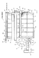
以下、図示実施例について説明すると、図1ないし図3は物品としてのLED素子1を分類する物品分類装置2を示している。
上記物品分類装置2は、図示しないLED製造装置から供給されたLED素子1を検査する検査手段3と、複数の分類トレイ4を保持するストッカ5と、検査結果に応じて上記ストッカ5に保持されたいずれかの分類トレイ4にLED素子1を移送する第1移載手段6と、上記ストッカ5に供給する空の分類トレイ4を準備する空トレイ供給手段7とから構成され、これらは図示しない制御手段によって制御される。
LED素子1は略長方形で上面が平坦な平板状に製造され、輝度などの特性や、搬送中における傷の有無等に応じて、複数のランクに分類されるようになっている。
上記分類トレイ4には、ひとつのLED素子1を収容可能な収容部が縦横にそれぞれ複数形成されており、また図2、図3に示すように、上記分類トレイ4は上下に積み重ねることが可能となっており、積み重ねる際に上記収容部に収容されたLED素子1が損傷しないようになっている。
そして以下の説明において、X方向とは図1における図示左右方向を指し、Y方向とは図示上下方向を指し、Z方向とは図2における図示上下方向を指すものとする。
Hereinafter, the illustrated embodiment will be described. FIGS. 1 to 3 show an
The
The LED element 1 is manufactured in a flat plate shape having a substantially rectangular shape and a flat upper surface, and is classified into a plurality of ranks according to characteristics such as luminance and the presence or absence of scratches during transportation.
The
In the following description, the X direction refers to the illustrated left and right direction in FIG. 1, the Y direction refers to the illustrated vertical direction, and the Z direction refers to the illustrated vertical direction in FIG.
上記検査手段3は、複数のLED素子1を収容した供給トレイ11から一つずつLED素子1を移載する第2移載手段12と、複数の載置台13aを備えるとともに各種の作業が行われる回転テーブル13とから構成されている。
上記供給トレイ11は上記分類トレイ4と同様、複数のLED素子1を収容するとともに上下に積み重ねることが可能となっており、第2移載手段12に隣接した供給ステージ3Aには、LED素子1を収容した供給トレイ11が複数枚積み重なった状態で供給されるようになっている。
この供給ステージ3Aに供給された供給トレイ11は、その後図示しない搬送手段により1枚ずつ上記回転テーブル13に近接した移載ステージ3Bに移動され、この移載ステージ3Bにおいて上記第2移載手段12が全てのLED素子1を回転テーブル13に移載すると、この空になった供給トレイ11はさらに隣接する排出ステージ3Cにおいて積み重ねられるようになっている。
上記第2移載手段12は従来公知であるため詳細な説明は省略するが、上記移載ステージ3Bに移動された供給トレイ11内のLED素子1を一つずつ吸着保持して、これを上記回転テーブル13に移載するようになっている。
The inspection means 3 includes a second transfer means 12 for transferring the LED elements 1 one by one from the supply tray 11 containing the plurality of LED elements 1 and a plurality of mounting tables 13a, and various operations are performed. The rotary table 13 is comprised.
The supply tray 11, similar to the
The supply tray 11 supplied to the
The second transfer means 12 is well known in the art and will not be described in detail. However, the LED elements 1 in the supply tray 11 moved to the
上記回転テーブル13には一つのLED素子1を載置可能な8つの載置台13aが等間隔に設けられており、該回転テーブル13はこの載置台13aのピッチに合わせて間欠的に回転するようになっている。
そして回転テーブル13は各載置台13aを、第2移載手段12に隣接する供給ステーション13Aと、上記LED素子1の輝度を測定する輝度測定ステーション13Bと、LED素子1の傷を検査する傷検査ステーション13Cと、これらの検査結果に基づいて所要のマークをLED素子1に所要の識別記号を付与するマークステーション13Dと、マークステーション13Dで付与されたマークを検査するマーク検査ステーション13Eと、上記ストッカ5に隣接する排出ステーション13Fとに停止させるようになっている。
上記輝度測定ステーション13BにはLED素子1の輝度を測定する図示しない測定装置が設けられ、また上記傷検査ステーション13CにはLED素子1の傷の有無を検査する図示しない検査装置が設けられている。
また上記マークステーション13Dには上記測定結果や検査結果に応じて所要のマークを付与するインクジェッタやレーザマーカなどが設けられ、上記マーク検査ステーション13Eには上記マークを検査する図示しない検査装置が設けられている。
そして、上記輝度測定ステーション13B、傷検査ステーション13C、マーク検査ステーション13Eにおける検査結果に応じて、制御手段は全てのLED素子1をA〜Iランクの9つのランクまたは不良品という合計10種類に分類するようになっており、この分類結果に応じて、上記制御手段が上記ストッカ5および第1移載手段6を制御するようになっている。
なお本実施例では、上記検査手段3に供給されるLED素子1の大部分がAランクに分類され、その他B〜GランクのLED素子1は中程度の頻度で発生し、H,IランクのLED素子1はさらに低頻度で発生するようになっている。
The rotating table 13 is provided with eight mounting tables 13a on which one LED element 1 can be mounted at equal intervals, and the rotating table 13 rotates intermittently according to the pitch of the mounting table 13a. It has become.
Then, the
The
The
Then, according to the inspection results at the
In the present embodiment, most of the LED elements 1 supplied to the inspection means 3 are classified into A rank, and the other B to G rank LED elements 1 are generated at a moderate frequency, and H and I rank The LED element 1 is generated at a lower frequency.
上記ストッカ5は、複数の分類トレイ4を載置可能な5段の第1〜第5スライド板21A〜21Eと、第1〜第5スライド板21A〜21Eを保持するとともにこれらをY方向に往復動させる駆動手段22とを備えている。
図1に示すように、第1〜第5スライド板21A〜21EにはそれぞれX方向に5枚、Y方向に2枚の合計10枚の分類トレイ4を載置可能となっており、これら第1〜第5スライド板21A〜21Eの上面に固定されたストッパ21aによって上記分類トレイ4は移動しないように保持されている。
また図2、図3に示すように、最上段に位置する第1スライド板21Aには分類トレイ4をZ方向に10枚積み重ねることが可能となっており、その下方の4つの第2〜第4スライド板21B〜21Eにはそれぞれ分類トレイ4をZ方向に5枚積み重ねることが可能となっている。
本実施例では第1スライド板21A上の10枚の分類トレイ4はいずれもAランクに分類されたLED素子1を収容するようになっており、第2スライド板21Bにおける図3の図示左側の5枚の分類トレイ4はBランクのLED素子1を、図示右側の5枚の分類トレイ4はCランクのLED素子1を収容するものとなっている。
これと同様、第3スライド板21Cにおける図示左側の5枚の分類トレイ4はDランクのLED素子1を、図示右側の5枚の分類トレイ4はEランクのLED素子1を、第4スライド板21Dにおける図示左側の5枚の分類トレイ4はFランクのLED素子1を、図示右側の5枚の分類トレイ4はGランクのLED素子1をそれぞれ収容するようになっている。
そして第5スライド板21Eでは、図示左側の5枚の分類トレイ4のうち、3枚の分類トレイ4はHランクのLED素子1を、2枚の分類トレイ4はIランクのLED素子1をそれぞれ収容し、図示右側の5枚の分類トレイ4は不良品と判定されたLED素子1を収容するようになっている。
なお、このような分類は一例であり、本実施例のストッカ5によれば最大50の種類に分類することが可能となっている。
The
As shown in FIG. 1, the first to
As shown in FIGS. 2 and 3, ten
In this embodiment, each of the ten
In the same manner, the five
In the
Such classification is merely an example, and according to the
上記駆動手段22は、上記第1〜第5スライド板21A〜21Eを保持するフレーム31と、該フレーム31に固定された5つのモータ32と、フレーム31の両側面に回転可能に設けられた5組のプーリー33と、上記モータ32の駆動軸32aとプーリー33との間に張設されたベルト34とから構成されている。
図2に示すように、上記フレーム31の内側面にはY方向に5組のスライドレール35が設けられており、第1〜第5スライド板21A〜21EのX方向両端部には該スライドレール35に沿って移動するためのスライド部材36が設けられている。
上記ベルト34には上記第1〜第5スライド板21A〜21Eの端部が連結されており、上記モータ32が駆動軸32aを回転させることで、ベルト34の回転に伴ってスライド板がY方向に進退動するようになっている。
上記駆動手段22によれば、第1〜第5スライド板21A〜21Eは通常図1における図示上方(図3では図示左方)の待機位置と、図1の図示下方(図3では図示右方)に位置する1列目の分類トレイ4だけが露出する第1移動位置と、図1の図示上方(図3では図示左方)に位置する2列目の分類トレイ4が露出する第2移動位置とにそれぞれ移動可能となっている。
なお図1、図3は、上記第3スライド板21Cが上記第2移動位置に移動した状態を示している。
そして第1〜第5スライド板21A〜21Eには、それぞれ図2の図示右方端に被検出部材37が設けられるとともに、上記フレーム31には近接センサー38が設けられている。
そして上記第1〜第5スライド板21A〜21Eがそれぞれ待機位置、第1、第2作動位置のそれぞれで停止すると、上記被検出部材37が上記近接センサー38に検出されて、制御手段が第1〜第5スライド板21A〜21Eの位置を認識するようになっている。
The driving means 22 includes a
As shown in FIG. 2, five sets of slide rails 35 are provided in the Y direction on the inner surface of the
End portions of the first to
According to the driving means 22, the first to
1 and 3 show a state where the
The first to fifth slide plates 21 </ b> A to 21 </ b> E are each provided with a
When the first to
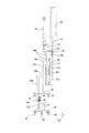
上記第1移載手段6は、LED素子1および分類トレイ4を吸着保持する第1吸着ヘッド41と、該第1吸着ヘッド41をX−Y−Zの各方向に移動させる第1移動手段42とから構成されている。
図4は上記第1吸着ヘッド41を図2と同じ方向から見た拡大正面図を示しており、上記第1移動手段42に固定される昇降部材43と、該昇降部材43に設けられたLED素子1を吸着保持するための素子用吸着カップ44と、昇降部材43に対してZ方向に昇降可能に設けられるとともに上記分類トレイ4を吸着保持するトレイ用吸着カップ45と、該トレイ用吸着カップ45を昇降させる昇降手段46とから構成されている。
The first transfer means 6 includes a
FIG. 4 shows an enlarged front view of the
上記素子用吸着カップ44は、上記昇降部材43の下端に2つのブラケット43a、43bを介して設けた保持部材47の下端部にY方向に2つ設けられ、それぞれ図示しない負圧発生手段に接続されている。また上記保持部材47は上記ブラケット43a、43bによって昇降部材43に対してX方向に離隔した位置に固定されている。
また上記保持部材47は、上記ブラケット43bに設けたレール43cおよびスライダ47aによって上記昇降部材43に対して昇降可能となっており、さらに上記保持部材47は、上記素子用吸着カップ44が保持するLED素子1への衝撃を和らげる第1アブソーバー48と、分類トレイ4のズレを検出する第1検出手段49とを備えている。
上記第1アブソーバー48は、素子用吸着カップ44がLED素子1を上方より吸着保持する際と、上記分類トレイ4の収容部にLED素子1を載置する際に、該素子用吸着カップ44が上昇するのを許容してLED素子1の損傷を防止するようになっている。
上記第1検出手段49は、素子用吸着カップ44が第1アブソーバー48により所定量以上上昇すると作動して、上記制御手段を介して所要の警告を発生させるようになっている。
Two
The holding
The
The first detection means 49 is activated when the
次に、上記トレイ用吸着カップ45は、上記素子用吸着カップ44を囲繞するように設けた略四角形のフレーム50の4隅に設けられるとともに、それぞれ図示しない負圧発生手段に接続されている。
上記昇降手段46は図示しないエア供給源に接続されたエアシリンダであって、該昇降手段46によって昇降されるロッド46aの下端に上記フレーム50が連結されている。
この昇降手段46は、上記フレーム50を昇降させることにより素子用吸着カップ44を下方に突出させて上記トレイ用吸着カップ45によりLED素子1を吸着保持可能とした状態と、トレイ用吸着カップ45を素子用吸着カップ44よりも下方に突出させて分類トレイ4を吸着保持可能とした状態とに切り換えるようになっている。
また上記昇降手段46は、上記昇降部材43に設けたレール43cに沿って上下に移動するスライダ51aを備えた支持部材51の上端に固定され、さらに上記ロッド46aはスライダ46bを介して支持部材51に設けたレール51bに沿って上下に移動するようになっている。
このように、上記昇降手段46の固定された支持部材51は上記昇降部材43に対して昇降することから、上記トレイ用吸着カップ45が分類トレイ4を上方より吸着保持する際と、上記分類トレイ4を積み重ねる際には、該トレイ用吸着カップ45の上昇が許容されるようになっている。
そして第1吸着ヘッド41は分類トレイ4のずれ等を検出するための第2検出手段52を備えており、この第2検出手段52は、上記昇降部材43に設けた近接スイッチ52aと、上記支持部材51に設けた検出片52bとから構成され、上記支持部材51が昇降部材43に対して上昇すると、近接スイッチ52aから検出片52bが離隔して制御手段にその信号が送信されるようになっている。
Next, the
The elevating means 46 is an air cylinder connected to an air supply source (not shown), and the
The elevating means 46 moves the
The elevating means 46 is fixed to the upper end of a
Thus, since the
The
上記第1移動手段42は、図1に示すようにフレーム31の上部にX方向に架設されたX方向レール53と、Y方向に設けられたY方向レール54と、Z方向に設けられたZ方向レール55とを備えている。
上記Y方向レール54は図示しない駆動手段によって上記X方向レール53に沿ってX方向に移動し、上記Z方向レール55は図示しない駆動手段によって上記Y方向レール54に沿ってY方向に移動し、上記第1吸着ヘッド41は図示しない駆動手段によって上記Z方向レール55に沿ってZ方向に移動するようになっている。
上記X方向レール53は図2に示すように、上記第1吸着ヘッド41を上記回転テーブル13の排出ステーション13Fの位置から、上記第1〜第5スライド板21A〜21Eに載置された図示右方端の分類トレイ4にかけて移動させるようになっている。
また上記Y方向レール54は図3に示すように、上記第1吸着ヘッド41を上記待機位置に位置する第1〜第5スライド板21A〜21Eよりも図示右方側に1行分だけ露出した分類トレイ4の範囲内で移動させるようになっている。
換言すると、第1吸着ヘッド41は水平なX−Y方向において、上記第1移動位置に移動したスライド板における1行目の5個の分類トレイ4か、もしくは上記第2移動位置に移動したスライド板における2行目の5個の分類トレイ4に対してLED素子1を載置可能な範囲で移動するようになっている。
そして上記Z方向レール55は図2に示すように、上記第1吸着ヘッド41を、上記素子用吸着カップ44が上記回転テーブル13の排出ステーション13FでLED素子1を吸着保持して分類トレイ4に収納するストロークと、上記トレイ用吸着カップ45が上記空トレイ供給手段7に保持された空の分類トレイ4を吸着保持して最上段の第1スライド板21Aに供給するストロークとがそれぞれ確保されるようになっている。
As shown in FIG. 1, the first moving means 42 includes an
The Y-
As shown in FIG. 2, the
Further, as shown in FIG. 3, the Y-
In other words, the
As shown in FIG. 2, the Z-
上記空トレイ供給手段7は、上記第1〜第5スライド板21A〜21Eの下方に設けられ、かつ上記第1吸着ヘッド41が第1移動手段42によってX−Y方向に移動可能な範囲の下方に設けられている。
空トレイ供給手段7は、フレーム61上に設けられるとともに上記分類トレイ4を載置するテーブル62と、該テーブル62を上記フレーム31に対して昇降させる多段シリンダ63とから構成されている。
上記テーブル62には図2、図3に示すようにX方向に3個、Y方向に1個の分類トレイ4を整列させることが可能となっており、その上部にはそれぞれ10枚程度の空の分類トレイ4を積み重ねた状態で載置することが可能となっている。
上記多段シリンダ63は図示しないエア供給源に接続されており、上記テーブルを段階的に上昇させることが可能となっており、テーブル62に載置された分類トレイ4における最上段の分類トレイ4が一定高さを維持するようにテーブル62を徐々に上昇させるとともに、最上段の分類トレイ4が上記第5スライド板21Eに干渉しない高さに保持するようになっている。
The empty tray supply means 7 is provided below the first to
The empty tray supply means 7 includes a table 62 on which the
2 and 3, it is possible to align three sorting
The
以下、上記構成を有する物品分類装置2の動作について説明する。
まず、ストッカ5における第1〜第5スライド板21A〜21Eには、それぞれ10枚の空の分類トレイ4が整列した状態で載置されており、これら分類トレイ4はZ方向に積み重ねられておらずに1枚ずつ載置され、これらは作業者によって手作業により行われる。
一方、上記検査手段3には、図示しないLED製造装置よりLED素子1を収容した供給トレイ11が複数段積み重ねられた状態で供給ステージ3Aに供給され、このうち最下段の供給トレイ11が移載ステージ3Bに移動される。
すると、上記第2移載手段12が供給トレイ11内のLED素子1を一つずつ吸着保持して、これを上記供給ステージ13Aに停止している回転テーブル13の載置台13a上に移載する。
この後、移載ステージ3Bの供給トレイ11から全てのLED素子1が移載されると、この供給トレイ11は隣接する排出ステージ3Cに移動されて積み重ねられるようになっている。
Hereinafter, the operation of the
First, ten
Meanwhile, the inspection means 3 is supplied to the
Then, the second transfer means 12 sucks and holds the LED elements 1 in the supply tray 11 one by one, and transfers them onto the mounting table 13a of the rotary table 13 stopped on the
Thereafter, when all the LED elements 1 are transferred from the supply tray 11 of the
次に、上記回転テーブル13の供給ステージ13Aに位置した載置台13aにLED素子1が移載されると、回転テーブル13は間欠的に回転して、上記輝度測定ステージ13Bで輝度の測定、傷検査ステージ13Cで傷の有無の検査をそれぞれ行い、上記マークステージ13Cでは上記測定結果および検査結果に応じて所要のマークが付与される。
その後、マーク検査ステージ13EでLED素子1に付されたマークが検査されると、制御手段はこれらの結果から各LED素子1がA〜Iランクまたは不良品の判定を行い、このLED素子1は上記排出ステージ13Fへと搬送される。
Next, when the LED element 1 is transferred to the mounting table 13a positioned on the
Thereafter, when the mark attached to the LED element 1 is inspected by the
まず、排出ステージ13Fに搬送されたLED素子1がAランクと判定された場合、制御手段は上記ストッカ5の駆動手段22を制御して、第1スライド板21Aを待機位置から第1停止位置まで移動させる。
一方、上記第1移載手段6では、上記第1吸着ヘッド41のトレイ用カップ45は昇降手段46によって素子用カップ44の上方に退避しており、その状態で上記第1移動手段42が第1吸着ヘッド41を排出ステージ13Fの上方に移動させる。
その後、第1吸着ヘッド41が下降して素子用カップ44がLED素子1を吸着保持すると、第1移動手段42により上昇、X−Y移動、下降して上記第1停止位置に位置している第1スライド板21Aにおける1列目の分類トレイ4にLED素子1を収容させる。
次に、例えばランクDと判定されたLED素子1が排出ステージ13Fに位置すると、制御手段は上記ストッカ5を制御して、上記第1スライド板21Aを待機位置に移動させるとともに第3スライド板21Cを第2停止位置まで移動させる(図3の状態)。
これにより、ランクDに対応する分類トレイ4を第1吸着ヘッド41の移動範囲の下方に位置することとなり、上記第1移載手段6は排出ステージ13FのLED素子1を吸着保持して、これを第3スライド板21Cにおける2列目の分類トレイ4に収容させる。
ここで制御手段は、第1〜第5スライド板21A〜21Eに載置された各分類トレイ4に対して最初のLED素子1を収容する際に、分類トレイ4のズレを確認するようになっている。
詳しく説明すると、制御手段はLED素子1を吸着保持した第1吸着ヘッド41を低速で下降させ、分類トレイ4がスライド板にズレ無く載置されている場合、LED素子1は抵抗無く分類トレイ4の収容部に収容されることから、上記素子用吸着カップ44は第1アブソーバー48によって若干上昇するものの、上記第1検出手段49は作動しないようになっている。
一方、上記分類トレイ4がスライド板にズレた状態で載置された場合、上記LED素子1が分類トレイ4の収容部に干渉してしまうため、上記素子用吸着カップ44は上記第1アブソーバー48によって所定量以上上昇してしまい、上記第1検出手段49が作動する。
すると、制御手段は図示しない警報手段により分類トレイ4がズレている旨の警告を出力し、作業者は人手によりこの分類トレイ4のズレを修正するようになっている。
First, when it is determined that the LED element 1 conveyed to the
On the other hand, in the first transfer means 6, the
Thereafter, when the
Next, for example, when the LED element 1 determined as rank D is positioned on the
Accordingly, the
Here, the control means checks the displacement of the
More specifically, the control means lowers the
On the other hand, when the
Then, the control means outputs a warning that the
その後、制御手段は排出ステージ13Fに位置したLED素子1のランクに応じて上記ストッカ5を制御し、該LED素子1のランクに応じた分類トレイ4を載置したスライド板を第1、第2移動位置まで移動させ、さらに第1移載手段6を制御して該LED素子1を対応する分類トレイ4へと収容させる。
制御手段は各分類トレイ4に収容したLED素子1の数量及び収容した位置を記憶しており、例えば第1スライド板21Aにおける1枚目の分類トレイ4に所定数量のLED素子1が収容されると、第1移載手段6は隣接した分類トレイ4にLED素子1を収容する。
その後、上記第1スライド板21Aにおける図1における1列目の5枚の分類トレイ4の全てに所要の数のLED素子1が収容されると、制御手段はその後第1スライド板21Aを第2移動位置まで移動させ、今度は2列目の5枚の分類トレイ4に対してLED素子1を収容させる。
なお、同じランクのLED素子1が排出ステージ13Fに連続して供給された場合には、そのつど第1〜第5スライド板21A〜21Eを待機位置に移動させる必要はなく、第1移動位置または第2移動位置に位置させたままとしてもよい。
Thereafter, the control means controls the
The control means stores the number and position of the LED elements 1 accommodated in each
After that, when the required number of LED elements 1 are accommodated in all of the five
In addition, when the LED element 1 of the same rank is continuously supplied to the
その後、例えば第1スライド板21Aの10枚の全ての分類トレイ4にLED素子1が収容されると、上記空トレイ供給手段7の空の分類トレイ4を該LED素子1を収容した分類トレイ4に積み重ねる作業を行う。
具体的には、制御手段が上記ストッカ5を制御して、第1〜第5スライド板21A〜21Eの全てを待機位置に移動させ、上記第1移載手段6を制御して、第1吸着ヘッド41の昇降手段46によりトレイ用吸着カップ45を素子用吸着カップ44の下方にまで下降させる。
続いて、制御手段は第1移載手段6のトレイ用吸着カップ45を用いて、上記空トレイ供給手段7に積み重ねられた空の分類トレイ4のうち最上段の分類トレイ4を吸着保持させ、該空の分類トレイ4を第1スライド板21Aの上方まで上昇させる。
すると、制御手段は第1スライド板21Aを第1移動位置まで移動させ、この状態で上記第1移載手段6により空の分類トレイ4がLED素子1を収容した分類トレイ4の上段に積み重ねられる。
このとき、制御手段は各スライド板に載置されている分類トレイ4の積み重ねられた枚数を記憶しており、また予め分類トレイ4を積み重ねる際における各段ごとの第1吸着ヘッド41のストローク量が登録されている。
このため、2枚目の分類トレイ4を第1スライド板21Aに載置された1枚目の分類トレイ4に積み重ねる場合、上記分類トレイ4を吸着保持した第1吸着ヘッド41は予め設定されたストロークだけ下降するようになっている。
このとき、1枚目の分類トレイ4と2枚目の分類トレイ4とがズレ無く載置されている場合、第1吸着ヘッド41が上記設定されたストロークだけ下降して、2枚目の分類トレイ4は抵抗無く1枚目の分類トレイ4に積み重なると、トレイ吸着用カップ45が第2アブソーバー51により若干上昇して、第2検出手段52が作動することとなる。
制御手段は、このように所定のストロークだけ第1吸着ヘッド41を下降させた後に第2検出手段52が作動した場合、1枚目の分類トレイ4がズレ無く載置されており、2枚目の分類トレイ4が正常に積み重ねられたものと判定する。
一方、1枚目の分類トレイ4と2枚目の分類トレイ4とがズレた状態で載置される場合、第1吸着ヘッド41が上記設定されたストロークだけ下降する前に、2枚目の分類トレイ4は1枚目の分類トレイ4に干渉し、第2検出手段52が作動することとなる。
制御手段は、このように所定のストロークだけ第1吸着ヘッド41を下降させる前に第2検出手段52が作動した場合、1枚目の分類トレイ4と2枚目の分類トレイ4とがズレて載置されたものと判定し、所要の警告を発生させる。
他方、何らかの理由で1枚目の分類トレイ4がスライド板に載置されていなかった場合、第1吸着ヘッド41が上記設定されたストロークだけ下降しても、第2検出手段52が作動しないこととなる。
制御手段は、このように所定のストロークだけ第1吸着ヘッド41を下降させても第2検出手段52が作動しなかった場合、1枚目の分類トレイ4がスライド板に載置されていないものと判定し、所要の警告を発生させる。
Thereafter, for example, when the LED elements 1 are accommodated in all ten
Specifically, the control unit controls the
Subsequently, the control means uses the
Then, the control means moves the
At this time, the control means stores the number of
Therefore, when the
At this time, when the
When the
On the other hand, when the
When the
On the other hand, when the
When the second detecting
このようにして、第1移動位置に移動した第1スライド板21Aの1列目の5枚の分類トレイ4の上部にそれぞれ空の分類トレイ4を積み重ねたら、今度は第1スライド板21Aを第2移動位置まで移動させて、同じように2列目の5枚の分類トレイ4の上部にそれぞれ空の分類トレイ4を積み重ねる。
また、例えば第3スライド板21Cにおける2列目に位置するランクDに対応する5枚の分類トレイ4に所定数のLED素子1が収容された場合も、制御手段は、第3スライド板21Cを第2移動位置まで移動させて、ランクDに対応する2列目の5枚の分類トレイ4の上部にそれぞれ空の分類トレイ4を積み重ねる。
一方制御手段は、上記空トレイ供給手段7を制御して、テーブル62に積み重ねされた状態で載置された空の分類トレイ4のうち、最上段に位置する分類トレイ4が所定の高さを維持するよう、上記多段シリンダ63によりテーブル62を所定量だけ上昇させるようになっている。
When the
For example, even when a predetermined number of LED elements 1 are accommodated in the five
On the other hand, the control means controls the empty tray supply means 7 so that, among the
そして、上記作業を繰り返すことにより第1スライド板21Aに分類トレイ4が10枚積み重ねられるか、もしくは第2〜第4スライド板21B〜21Eのいずれかに分類トレイ4が5枚積み重ねられると、制御手段は物品分類装置2を停止させる。
そして作業者がこの所定枚数積み重ねられた分類トレイ4を除去し、新たに1枚の空の分類トレイ4をその代わりに載置すると、再び上述した作業が開始されてLED素子1の分類が行われる。
このとき、分類トレイ4は上記第1検出手段49および第2検出手段52によってズレの無いことが判明しているため、この積み重ねた分類トレイ4に最初のLED素子1を収容する際において、上述したように上記第1吸着ヘッド41を低速で下降させる必要はない。
また上記空トレイ供給手段7の分類トレイ4がなくなった場合も、制御手段が物品分類装置2を停止させて、作業者が空の分類トレイ4を補充するようになっている。
Then, by repeating the above operation, when 10
Then, when the operator removes the predetermined number of the
At this time, since the
Further, even when the
以上のように、上記実施例にかかる物品分類装置2によれば、上記ストッカ5に複数の第1〜第5スライド板21A〜21Eを設け、それぞれに複数枚ずつ分類トレイ4を載置することから、省スペースながら多数の種類にLED素子1を分類することができる。
また、所要の分類トレイ4に所定数のLED素子1が収容されると、その分類トレイ2の上方に上記空トレイ供給手段7に保持された空の分類トレイ4が積み重ねられるため、物品分類装置2の稼働時間を長くすることができる。
ここで、上記空の分類トレイ4は上記LED素子4を移載する第1吸着ヘッド41を用いて積み重ねられるため、空の分類トレイ4を搬送するための別途の搬送手段を設ける必要が無く、低コストに空の分類トレイ4の補充を行うことができる。
さらに、上記ストッカ5により、第1〜第5スライド板21A〜21Eが待機位置から第1、第2移動位置に移動することで、スライド板の分類トレイ4は1列ずつ露出し、上記第1移載手段における第1吸着ヘッド41の移動範囲はこの露出した1列の分類トレイ4の範囲内としていることから、該第1吸着ヘッド41の移動範囲を最小限として、効率的に分類を行うことが可能となっている。
As described above, according to the
Further, when a predetermined number of LED elements 1 are accommodated in a required
Here, since the
Furthermore, the first to
なお、上記実施例では物品としてLED素子1を移載しているが、移載される物品はLED素子1に限られないことはもちろんであり、また上記検査手段3におけるLED素子1の検査内容についても、上記実施例に限られないことはもちろんである。
また、本実施例では5枚の第1〜第5スライド板21A〜21Eを設けているが、この枚数に限定されるものではなく、また各スライド板に載置する分類トレイ4の数も、縦方向に5個、横方向に2個に限定されるものでもない。
例えば、横方向に3個整列させる場合、上記駆動手段22はスライド板を1行目の分類トレイ4が露出する第1停止位置と、2行目の分類トレイ4が露出する第2停止位置と、3行目の分類トレイ4が露出する第3停止位置とに位置させるようにすればよい。
さらに、上記実施例では上記第1移載手段6における第1吸着ヘッド41の移動範囲は、露出した1列の分類トレイ4の範囲としているが、タクトタイムが長くならない範囲で、その移動範囲を2列以上の複数列の分類トレイ4の範囲としてもよい。
そして上記実施例に対し、予め作業者の人手により第1〜第5スライド板21A〜21Eのそれぞれに分類トレイ4を載置せず、上記第1移載手段6が上記空トレイ供給手段7に保持された分類トレイ4を吸着保持して、第1〜第5スライド板21A〜21Eのそれぞれに載置するようにしてもよい。
In addition, although the LED element 1 is transferred as an article in the above embodiment, the article to be transferred is not limited to the LED element 1, and the inspection contents of the LED element 1 in the inspection means 3 are of course. Of course, the present invention is not limited to the above embodiment.
In this embodiment, five first to
For example, in the case of arranging three in the horizontal direction, the driving means 22 has a first stop position at which the first
Furthermore, in the above embodiment, the moving range of the
And with respect to the embodiment, the sorting
1 LED素子 2 物品分類装置
3 検査手段 4 分類トレイ
5 ストッカ 6 第1移載手段
7 空トレイ供給手段 21A〜21E 第1〜第5スライド板
22 駆動手段 44 素子用吸着カップ
45 トレイ用吸着カップ 46 昇降手段
DESCRIPTION OF SYMBOLS 1
Claims (4)
上記ストッカは、分類トレイを複数整列した状態で載置するスライド板と、該スライド板を上下に複数段保持するとともに各スライド板を水平方向に往復動させる駆動機構とを備え、
さらに上記ストッカに近接した位置に、空の分類トレイを保持する空トレイ供給手段を設け、
上記移載手段が所要の分類トレイに物品を移載する際には、上記ストッカの駆動機構がスライド板を移動させて、該物品に対応した分類トレイが露出されるようにし、
所要の分類トレイに所定数の物品が収容された際には、上記ストッカの駆動機構がスライド板を移動させて、上記所定数の物品が収容された分類トレイが露出されるようにし、上記移載手段が上記空トレイ供給手段の空の分類トレイを保持して、該空の分類トレイを上記所定数の物品が収容された分類トレイの上部に積み重ねることを特徴とする物品分類装置。 Article classification comprising a stocker on which a plurality of classification trays for storing articles are placed, and transfer means for transferring the articles supplied to the supply position to a required classification tray in the stocker according to the classification result In the device
The stocker includes a slide plate that is placed in a state where a plurality of sorting trays are aligned, and a drive mechanism that holds the slide plate in multiple stages up and down and reciprocates each slide plate in the horizontal direction.
Furthermore, an empty tray supply means for holding an empty classification tray is provided at a position close to the stocker,
When the transfer means transfers the article to the required classification tray, the drive mechanism of the stocker moves the slide plate so that the classification tray corresponding to the article is exposed,
When a predetermined number of articles are stored in a required classification tray, the drive mechanism of the stocker moves the slide plate so that the classification tray storing the predetermined number of articles is exposed, and the transfer is performed. An article classification apparatus, wherein the loading means holds the empty classification tray of the empty tray supply means and stacks the empty classification tray on top of the classification tray in which the predetermined number of articles are stored.
上記移載手段による作動範囲を、上記スライド板が退避位置より上記移動位置に移動されることにより露出した1行分の分類トレイに対して物品を移載可能な範囲としたことを特徴とする請求項1に記載の物品分類装置。 A plurality of the classification trays are arranged on each slide plate in the row direction and the column direction, and the stocker driving mechanism includes a retreat position where the slide plates overlap each other and a retreat position where the slide plates overlap each other. Move to the moving position where the above-mentioned sorting tray that is aligned by moving in the row direction from the position is exposed,
The operating range of the transfer means is a range in which articles can be transferred to the classification tray for one row exposed by moving the slide plate from the retracted position to the moving position. The article classification apparatus according to claim 1.
かつ、上記ストッカにおける全てのスライド板が上記退避位置に位置されると、空の分類トレイが上記移載手段による作動範囲内に露出されることを特徴とする請求項2に記載の物品分類装置。 The empty tray supply means holds the empty classification tray at a position below the lowest slide plate in the stocker,
3. The article classification apparatus according to claim 2, wherein when all the slide plates in the stocker are positioned at the retracted position, an empty classification tray is exposed within an operating range of the transfer means. .
物品を吸着保持する際には、上記昇降手段が上記物品用吸着カップを下方に突出させ、空の分類トレイを吸着保持する際には、上記トレイ用吸着カップを下方に突出させることを特徴とする請求項1ないし請求項3のいずれかに記載の物品分類装置。 The transfer means switches the relative height of the article suction cup for sucking and holding the article, the tray suction cup for sucking and holding the classification tray, and the article suction cup and the tray suction cup. Elevating means,
When the article is sucked and held, the elevating means projects the article suction cup downward, and when sucking and holding an empty classification tray, the tray suction cup is projected downward. The article classification apparatus according to any one of claims 1 to 3.
Priority Applications (5)
| Application Number | Priority Date | Filing Date | Title |
|---|---|---|---|
| JP2010096680A JP5589525B2 (en) | 2010-04-20 | 2010-04-20 | Article classification device |
| MYPI2011001529A MY157709A (en) | 2010-04-20 | 2011-04-06 | Article sorting apparatus |
| TW100112385A TWI500940B (en) | 2010-04-20 | 2011-04-11 | Item sorting device |
| KR1020110036005A KR101776855B1 (en) | 2010-04-20 | 2011-04-19 | Apparatus for sorting products |
| CN201110098447.3A CN102259095B (en) | 2010-04-20 | 2011-04-20 | Apparatus for sorting article |
Applications Claiming Priority (1)
| Application Number | Priority Date | Filing Date | Title |
|---|---|---|---|
| JP2010096680A JP5589525B2 (en) | 2010-04-20 | 2010-04-20 | Article classification device |
Publications (2)
| Publication Number | Publication Date |
|---|---|
| JP2011226905A JP2011226905A (en) | 2011-11-10 |
| JP5589525B2 true JP5589525B2 (en) | 2014-09-17 |
Family
ID=45006037
Family Applications (1)
| Application Number | Title | Priority Date | Filing Date |
|---|---|---|---|
| JP2010096680A Active JP5589525B2 (en) | 2010-04-20 | 2010-04-20 | Article classification device |
Country Status (5)
| Country | Link |
|---|---|
| JP (1) | JP5589525B2 (en) |
| KR (1) | KR101776855B1 (en) |
| CN (1) | CN102259095B (en) |
| MY (1) | MY157709A (en) |
| TW (1) | TWI500940B (en) |
Families Citing this family (8)
| Publication number | Priority date | Publication date | Assignee | Title |
|---|---|---|---|---|
| JP5950183B2 (en) * | 2012-01-24 | 2016-07-13 | 澁谷工業株式会社 | Article inspection apparatus and article classification apparatus provided with the article inspection apparatus |
| CN102785798A (en) * | 2012-04-07 | 2012-11-21 | 杭州中为光电技术股份有限公司 | Method for using blanking barrel of high-capacity light-emitting diode (LED) sorting machine |
| CN103121014B (en) * | 2013-02-27 | 2015-09-02 | 上海轩田工业设备有限公司 | A kind of lens quality automatic checkout equipment with automatic sorting mechanism |
| TWI588074B (en) * | 2016-10-24 | 2017-06-21 | Automatic material storage machine for storage equipment | |
| CN108840076A (en) * | 2018-08-08 | 2018-11-20 | 苏州精濑光电有限公司 | A kind of classification stacking device |
| TWI744665B (en) * | 2019-07-12 | 2021-11-01 | 威光自動化科技股份有限公司 | Method and device for automatically sorting and collecting plate parts |
| CN111203398B (en) * | 2020-02-28 | 2022-07-12 | 清陶(昆山)自动化装备有限公司 | Battery detection grading system |
| JP7430154B2 (en) * | 2021-03-29 | 2024-02-09 | Towa株式会社 | Processing equipment and method for manufacturing processed products |
Family Cites Families (9)
| Publication number | Priority date | Publication date | Assignee | Title |
|---|---|---|---|---|
| JPS57211746A (en) * | 1981-06-23 | 1982-12-25 | Fujitsu Ltd | Wafer conveying apparatus |
| JP3739844B2 (en) * | 1995-12-19 | 2006-01-25 | 株式会社アドバンテスト | Stocker section of handler device |
| JP3644567B2 (en) * | 1997-04-08 | 2005-04-27 | 株式会社アドバンテスト | Handler tray transfer device |
| JP4171119B2 (en) * | 1998-11-25 | 2008-10-22 | 株式会社アドバンテスト | Tray holding device, component handling device, and component classification method |
| JP2000206191A (en) * | 1999-01-11 | 2000-07-28 | Advantest Corp | Test device of electronic component board |
| JP2002255315A (en) * | 2001-02-26 | 2002-09-11 | Ando Electric Co Ltd | Tray accommodation device |
| JP4401616B2 (en) * | 2002-03-14 | 2010-01-20 | ヤマハ発動機株式会社 | Electronic component inspection equipment |
| JP4028263B2 (en) * | 2002-03-15 | 2007-12-26 | ヤマハ発動機株式会社 | Parts storage device |
| CN201143504Y (en) * | 2007-10-18 | 2008-11-05 | 南京熊猫仪器仪表有限公司 | Device for arraying, sorting and overlapping SMD components |
-
2010
- 2010-04-20 JP JP2010096680A patent/JP5589525B2/en active Active
-
2011
- 2011-04-06 MY MYPI2011001529A patent/MY157709A/en unknown
- 2011-04-11 TW TW100112385A patent/TWI500940B/en active
- 2011-04-19 KR KR1020110036005A patent/KR101776855B1/en active IP Right Grant
- 2011-04-20 CN CN201110098447.3A patent/CN102259095B/en active Active
Also Published As
| Publication number | Publication date |
|---|---|
| CN102259095B (en) | 2014-08-20 |
| MY157709A (en) | 2016-07-15 |
| JP2011226905A (en) | 2011-11-10 |
| TW201202110A (en) | 2012-01-16 |
| KR20110117005A (en) | 2011-10-26 |
| KR101776855B1 (en) | 2017-09-08 |
| CN102259095A (en) | 2011-11-30 |
| TWI500940B (en) | 2015-09-21 |
Similar Documents
| Publication | Publication Date | Title |
|---|---|---|
| JP5589525B2 (en) | Article classification device | |
| US20150291371A1 (en) | Transport system | |
| JP4594167B2 (en) | IC handler | |
| CN110126445B (en) | Silk screen printing production line | |
| CN113697513B (en) | Layered tray layered feeding device | |
| JP2017095282A (en) | Article transfer device | |
| CN115355788A (en) | PCB module automatic test platform and control method | |
| JP5635835B2 (en) | Wafer supply device and chip bonding device | |
| CN108971027B (en) | Battery detection mechanism | |
| JP4992668B2 (en) | Container exchange device and container exchange method | |
| CN111921878A (en) | Automatic warehouse code scanning classification method | |
| JP2013018604A (en) | Article sorting apparatus | |
| CN216335291U (en) | Feeding and discharging mechanism for material tray | |
| JP5921628B2 (en) | Wafer supply device and chip bonding device | |
| KR20140017046A (en) | Apparatus for sorting led module bar | |
| JP4873364B2 (en) | Sheet-like member storage device | |
| CN218476165U (en) | Marking device | |
| CN220547302U (en) | Screening device | |
| CN110976343A (en) | AOI check out test set | |
| KR20160052192A (en) | Apparatus for transferring substrate and apparatus for inspecting substrate including the same | |
| CN220519382U (en) | Automatic material collecting equipment | |
| CN220222709U (en) | Discharging device and cleaning machine | |
| KR100683962B1 (en) | Back light unit loading apparatus | |
| CN112974291B (en) | Continuous automatic detection equipment for assembled flexible board and use method thereof | |
| CN211479997U (en) | Chip arrangement machine |
Legal Events
| Date | Code | Title | Description |
|---|---|---|---|
| A621 | Written request for application examination |
Free format text: JAPANESE INTERMEDIATE CODE: A621 Effective date: 20130329 |
|
| A977 | Report on retrieval |
Free format text: JAPANESE INTERMEDIATE CODE: A971007 Effective date: 20140130 |
|
| A131 | Notification of reasons for refusal |
Free format text: JAPANESE INTERMEDIATE CODE: A131 Effective date: 20140218 |
|
| A521 | Written amendment |
Free format text: JAPANESE INTERMEDIATE CODE: A523 Effective date: 20140415 |
|
| TRDD | Decision of grant or rejection written | ||
| A01 | Written decision to grant a patent or to grant a registration (utility model) |
Free format text: JAPANESE INTERMEDIATE CODE: A01 Effective date: 20140701 |
|
| A61 | First payment of annual fees (during grant procedure) |
Free format text: JAPANESE INTERMEDIATE CODE: A61 Effective date: 20140714 |
|
| R150 | Certificate of patent or registration of utility model |
Ref document number: 5589525 Country of ref document: JP Free format text: JAPANESE INTERMEDIATE CODE: R150 |