JP5585827B2 - Valve timing control device - Google Patents
Valve timing control device Download PDFInfo
- Publication number
- JP5585827B2 JP5585827B2 JP2010155998A JP2010155998A JP5585827B2 JP 5585827 B2 JP5585827 B2 JP 5585827B2 JP 2010155998 A JP2010155998 A JP 2010155998A JP 2010155998 A JP2010155998 A JP 2010155998A JP 5585827 B2 JP5585827 B2 JP 5585827B2
- Authority
- JP
- Japan
- Prior art keywords
- rotating body
- side rotating
- taper
- seal member
- driven
- Prior art date
- Legal status (The legal status is an assumption and is not a legal conclusion. Google has not performed a legal analysis and makes no representation as to the accuracy of the status listed.)
- Expired - Fee Related
Links
Images


Classifications
-
- F—MECHANICAL ENGINEERING; LIGHTING; HEATING; WEAPONS; BLASTING
- F01—MACHINES OR ENGINES IN GENERAL; ENGINE PLANTS IN GENERAL; STEAM ENGINES
- F01L—CYCLICALLY OPERATING VALVES FOR MACHINES OR ENGINES
- F01L1/00—Valve-gear or valve arrangements, e.g. lift-valve gear
- F01L1/34—Valve-gear or valve arrangements, e.g. lift-valve gear characterised by the provision of means for changing the timing of the valves without changing the duration of opening and without affecting the magnitude of the valve lift
- F01L1/344—Valve-gear or valve arrangements, e.g. lift-valve gear characterised by the provision of means for changing the timing of the valves without changing the duration of opening and without affecting the magnitude of the valve lift changing the angular relationship between crankshaft and camshaft, e.g. using helicoidal gear
- F01L1/3442—Valve-gear or valve arrangements, e.g. lift-valve gear characterised by the provision of means for changing the timing of the valves without changing the duration of opening and without affecting the magnitude of the valve lift changing the angular relationship between crankshaft and camshaft, e.g. using helicoidal gear using hydraulic chambers with variable volume to transmit the rotating force
- F01L2001/3445—Details relating to the hydraulic means for changing the angular relationship
- F01L2001/34479—Sealing of phaser devices
Description
本発明は、自動車等の内燃機関の吸気弁および排気弁の開閉タイミングを、運転状態に応じて調節する弁開閉時期制御装置に関する。 The present invention relates to a valve opening / closing timing control device that adjusts the opening / closing timing of an intake valve and an exhaust valve of an internal combustion engine such as an automobile in accordance with an operating state.
従来、クランクシャフトに対して同期回転する駆動側回転体と、駆動側回転体に対して同軸上に配置され、内燃機関の弁開閉用のカムシャフトに同期回転する従動側回転体と、で流体圧室を形成し、従動側回転体に設けられた仕切部によって流体圧室を遅角室と進角室とに仕切り、遅角室及び進角室に対して作動流体を給排して、駆動側回転体に対する従動側回転体の相対回転位相を制御する弁開閉時期制御装置がある。 Conventionally, a drive-side rotator that rotates synchronously with a crankshaft, and a driven-side rotator that is arranged coaxially with the drive-side rotator and rotates synchronously with a camshaft for opening and closing a valve of an internal combustion engine, Forming a pressure chamber, partitioning the fluid pressure chamber into a retard chamber and an advance chamber by a partition provided on the driven side rotating body, supplying and discharging working fluid to and from the retard chamber and the advance chamber; There is a valve opening / closing timing control device for controlling the relative rotation phase of the driven side rotating body with respect to the driving side rotating body.
この種の弁開閉時期制御装置においては、遅角室と進角室との間での作動流体の漏洩を防止する必要があり、例えば、特許文献1に記載の弁開閉時期制御装置は、仕切部(文献では「ベーン」)のうち駆動側回転体(文献では「ハウジング」)もしくは従動側回転体(文献では「ベーン部材」)に対向する位置と、駆動側回転体もしくは従動側回転体のうち仕切部に対向する位置と、にシール部材を配設している。
In this type of valve opening / closing timing control device, it is necessary to prevent leakage of the working fluid between the retard chamber and the advance chamber. For example, the valve opening / closing timing control device described in
弁開閉時期制御装置において、駆動側回転体は円筒形状であるため、通常、押し出し成形によって成形される。このとき、押し出し成形によって得られた駆動側回転体の内周壁は耐摩耗性に劣るものが多い。そこで、特許文献1のように、駆動側回転体の内周壁に自己潤滑性樹脂被膜やアルマイト被膜を施して、耐摩耗性を向上させる必要があった。
In the valve opening / closing timing control device, since the drive side rotating body has a cylindrical shape, it is usually formed by extrusion molding. At this time, the inner peripheral wall of the drive side rotating body obtained by extrusion molding is often inferior in wear resistance. Therefore, as in
一方、駆動側回転体をダイキャストによって製造すると、押し出し成形に比べて耐摩耗性が向上する。このため、駆動側回転体の内周壁に自己潤滑性樹脂被膜やアルマイト被膜を施して、耐摩耗性を向上させる必要はない。しかしながら、ダイキャストによる製造時には、成形された駆動側回転体を型から容易に抜き出せるよう駆動側回転体の内周壁に抜きテーパが形成され、この抜きテーパを除去するために、駆動側回転体の内周壁を加工する必要があった。また、抜きテーパの除去のための加工に際し、ダイキャストによる製造の際に回転体の内部に形成される巣(空洞)が表面に露出してしまい、シール部材によるシール性を低下させるおそれがある。 On the other hand, when the driving side rotating body is manufactured by die casting, the wear resistance is improved as compared with the extrusion molding. For this reason, it is not necessary to improve the wear resistance by applying a self-lubricating resin coating or an alumite coating to the inner peripheral wall of the drive side rotor. However, at the time of manufacturing by die-casting, a taper is formed on the inner peripheral wall of the drive-side rotator so that the molded drive-side rotator can be easily extracted from the mold. It was necessary to machine the inner peripheral wall of. Further, when processing for removing the taper taper, a nest (cavity) formed inside the rotating body during the production by die casting is exposed to the surface, which may reduce the sealing performance by the sealing member. .
本発明の目的は、駆動側回転体や従動側回転体がダイキャストで製造される際に形成される抜きテーパを加工することなく、遅角室と進角室との間での作動流体の漏洩を防止するシール部材の組付けが可能な弁開閉時期制御装置を提供することにある。 The object of the present invention is to reduce the working fluid between the retarding chamber and the advance chamber without processing the draft taper formed when the driving side rotating body or the driven side rotating body is manufactured by die casting. An object of the present invention is to provide a valve timing control device capable of assembling a seal member for preventing leakage.
本発明に係る弁開閉時期制御装置の第1特徴構成は、クランクシャフトに対して同期回転する駆動側回転体と、前記駆動側回転体に対して同軸上に配置され、内燃機関の弁開閉用のカムシャフトに同期回転する従動側回転体と、前記駆動側回転体と前記従動側回転体とで形成された流体圧室を遅角室と進角室とに仕切るよう前記駆動側回転体及び前記従動側回転体の少なくとも一方に設けられた仕切部と、前記仕切部のうち前記駆動側回転体もしくは前記従動側回転体に対向する位置、または、前記駆動側回転体もしくは前記従動側回転体のうち前記仕切部に対向する位置に配設されて、前記駆動側回転体と前記従動側回転体との相対回転に基づく前記遅角室と前記進角室との間での作動流体の漏洩を防止するシール部材と、弾性変形に基づく付勢力によって、前記シール部材を前記仕切部の側から前記駆動側回転体もしくは前記従動側回転体の側へ、または、前記シール部材を前記駆動側回転体もしくは前記従動側回転体の側から前記仕切部の側へ付勢する付勢部材と、を備え、前記駆動側回転体は、前記カムシャフトに接続される側とは反対側に設けられる第1プレートと、前記カムシャフトに接続される側に設けられる第2プレートと、を備え、前記駆動側回転体及び前記従動側回転体の少なくとも何れか一方をダイキャストで製造し、当該ダイキャストで製造された回転体のうち前記仕切部及び前記仕切部に対向する面の少なくとも何れか一方が抜きテーパの傾斜面で構成され、前記抜きテーパの傾斜面に当接するよう配設された前記シール部材は、前記第1プレート及び前記第2プレートに密接するよう、前記第1プレートに接触する面と前記傾斜面に当接する対向面とがなす角度、及び、前記第2プレートに接触する面と前記傾斜面に当接する対向面とがなす角度のうち、一方を鋭角とし、他方を鈍角とした点にある。 A first characteristic configuration of a valve opening / closing timing control device according to the present invention is a drive-side rotator that rotates synchronously with a crankshaft, and is arranged coaxially with respect to the drive-side rotator and is used for opening and closing a valve of an internal combustion engine A driven-side rotator that rotates synchronously with the camshaft, and a drive-side rotator that partitions a fluid pressure chamber formed by the drive-side rotator and the driven-side rotator into a retard chamber and an advance chamber; A partition provided in at least one of the driven-side rotator, and a position of the partition facing the drive-side rotator or the driven-side rotator, or the drive-side rotator or the driven-side rotator Of the working fluid between the retard chamber and the advance chamber based on the relative rotation of the drive side rotary body and the driven side rotary body. Based on the sealing member to prevent By the urging force, the seal member is moved from the partition side to the drive side rotating body or the driven side rotating body, or the seal member is moved from the drive side rotating body or the driven side rotating body side. An urging member that urges the partition portion, and the drive-side rotator is connected to the camshaft and a first plate provided on a side opposite to the side connected to the camshaft. A second plate provided on the side, and at least one of the driving side rotating body and the driven side rotating body is manufactured by die casting, and the partition portion and the partitioning portion of the rotating body manufactured by die casting the partition portion at least one of a surface facing the is composed of the inclined surface of the draft taper, said sealing member disposed so as to abut against the inclined surface of the draft taper, said first plate and The angle formed by the surface that contacts the first plate and the facing surface that contacts the inclined surface so as to be in close contact with the second plate, and the surface that contacts the second plate and the facing surface that contacts the inclined surface Of these angles, one is an acute angle and the other is an obtuse angle .
本構成によると、ダイキャストで製造された駆動側回転体及び従動側回転体のうち仕切部及び仕切部に対向する面の少なくとも一方に抜きテーパの傾斜面が存在する。そして、仕切部と仕切部に対向する面との間には、シール部材とシール部材を仕切部の側または仕切部に対向する駆動側回転体もしくは従動側回転体の側へ付勢する付勢部材とが位置する。すなわち、シール部材及び付勢部材が抜きテーパの傾斜を吸収し、シール部材が、仕切部と仕切部に対向する駆動側回転体もしくは従動側回転体の側との間の空間の気密性を確保する。こうして、ダイキャストで製造することで、回転体の耐摩耗性が向上し、さらに、回転体に形成される抜きテーパの切削加工が不要となった。また、抜きテーパを切削加工しないので、ダイキャストによる製造の際に回転体の内部に形成される巣(空洞)が表面に露出するおそれもなくなった。 According to this configuration, there is a tapered tapered inclined surface on at least one of the partitioning portion and the surface facing the partitioning portion of the driving side rotating body and the driven side rotating body manufactured by die casting. And between the partition part and the surface facing the partition part, a biasing force for biasing the seal member and the seal member toward the partition part side or the drive side rotating body or the driven side rotary body facing the partition part. The member is located. In other words, the sealing member and the biasing member absorb the inclination of the taper, and the sealing member ensures the airtightness of the space between the partitioning portion and the drive side rotating body or the driven side rotating body facing the partitioning portion. To do. Thus, by die-casting, the wear resistance of the rotating body is improved, and further, the punching taper formed on the rotating body is not required to be cut. In addition, since the punch taper is not cut, there is no possibility that a nest (cavity) formed inside the rotating body during the die casting manufacturing process is exposed on the surface.
本発明に係る弁開閉時期制御装置の第2特徴構成は、前記駆動側回転体及び前記従動側回転体の少なくとも何れか一方の厚み方向に、前記テーパが窄まる方向へ前記付勢部材の付勢力を発揮するようシール部材に対する当接部を有する点にある。 A second characteristic configuration of the valve timing control device according to the present invention is that the biasing member is applied in a direction in which the taper is narrowed in a thickness direction of at least one of the driving side rotating body and the driven side rotating body. It is in the point which has a contact part with respect to a sealing member so that force may be exhibited.
駆動側回転体及び前記従動側回転体の少なくとも何れか一方に形成された抜きテーパに対し、シール部材が当接し、このシール部材を付勢部材によって付勢する場合、抜きテーパの傾斜の影響を受けて、シール部材が回転体の厚み方向において抜きテーパが拡がる方向に移動し易い。
しかし、本構成のように、駆動側回転体及び前記従動側回転体の少なくとも何れか一方の厚み方向に、テーパが窄まる方向へ付勢部材の付勢力を発揮するようシール部材に対する当接部を有すると、シール部材は付勢部材によってテーパが窄まる方向へ付勢され、シール部材の抜きテーパが拡がる方向への移動が抑制される。こうして、シール部材が抜きテーパの傾斜面に対して確実に当接して気密性が確保される。
When the seal member abuts against the draft taper formed on at least one of the driving side rotary body and the driven side rotary body, and the seal member is biased by the biasing member, the influence of the slope of the draft taper is affected. In response, the seal member can easily move in the direction in which the punch taper expands in the thickness direction of the rotating body.
However, as in this configuration, in the thickness direction of at least one of the driving-side rotator and the driven-side rotator, the abutting portion with respect to the seal member so as to exert the urging force of the urging member in a direction in which the taper narrows. , The seal member is urged by the urging member in the direction in which the taper is narrowed, and the movement of the seal member in the direction in which the extraction taper is expanded is suppressed. In this way, the sealing member is surely brought into contact with the inclined surface of the punching taper to ensure airtightness.
本発明に係る弁開閉時期制御装置の第3特徴構成は、前記駆動側回転体及び前記従動側回転体に形成される前記抜きテーパの一方の傾斜面に対し、対向する他方の傾斜面が平行に形成され、前記駆動側回転体もしくは前記従動側回転体における前記仕切部に対向する位置、及び、前記仕切部における前記駆動側回転体もしくは前記従動側回転体に対向する位置のいずれもが前記抜きテーパの傾斜面で構成された点にある。 According to a third characteristic configuration of the valve opening / closing timing control device according to the present invention, the opposite inclined surface is parallel to one inclined surface of the draft taper formed on the driving side rotating body and the driven side rotating body. Each of the position facing the partitioning portion in the driving side rotating body or the driven side rotating body, and the position facing the driving side rotating body or the driven side rotating body in the partitioning portion. It is in the point comprised by the inclined surface of the drawing taper.
本構成のように、駆動側回転体及び従動側回転体に抜きテーパが形成されるとともに、そのうちの一方の傾斜面に対し、対向する他方の傾斜面が平行に形成され、駆動側回転体もしくは従動側回転体における仕切部に対向する位置、及び、仕切部における駆動側回転体もしくは従動側回転体に対向する位置のいずれもが抜きテーパの傾斜面で構成されていると、駆動側回転体もしくは従動側回転体と仕切部との間の空間は、回転体の厚み方向において一定の間隔となる。つまり、駆動側回転体及び従動側回転体に形成された一方の抜きテーパの傾斜は、他方の抜きテーパの傾斜によって相殺される。したがって、シール部材及び付勢部材は、抜きテーパの傾斜の影響をそれほど受けない状態で、駆動側回転体もしくは従動側回転体と仕切部との間に配設することができ、気密性が確保される。 As in this configuration, the drive-side rotator and the driven-side rotator are formed with a taper, and the other inclined surface is formed in parallel with one of the inclined surfaces, and the drive-side rotator or When both the position facing the partitioning portion in the driven side rotating body and the position facing the driving side rotating body or the driven side rotating body in the partitioning portion are formed by a tapered tapered surface, the driving side rotating body Alternatively, the space between the driven-side rotator and the partition portion is a constant interval in the thickness direction of the rotator. That is, the inclination of one drafting taper formed on the driving side rotary body and the driven side rotary body is offset by the slope of the other drafting taper. Therefore, the seal member and the urging member can be disposed between the driving side rotating body or the driven side rotating body and the partition portion in a state where the sealing member and the biasing member are not significantly affected by the inclination of the draft taper, and airtightness is ensured. Is done.
本発明に係る弁開閉時期制御装置の第4特徴構成は、前記駆動側回転体に対向する位置に配設された前記シール部材において、径方向外側の外周面に面取り部もしくは溝を形成してある点にある。 According to a fourth characteristic configuration of the valve timing control device according to the present invention, a chamfered portion or a groove is formed on the outer circumferential surface on the radially outer side in the seal member disposed at a position facing the driving side rotating body. There is a point.
駆動側回転体や従動側駆動体をダイキャストで製造すると、耐摩耗性は向上するものの強度は鋳鉄材料と比較して低下する。また、弁開閉時期制御装置では、エンジンオイルが用いられ、シールの摺動部分から微小ながら異物が発生する。この異物がシール部材と駆動側回転体、もしくは、シール部材と従動側駆動体との間に介在し、相対移動時に異物が研磨剤として作用して、駆動側回転体、もしくは、従動側駆動体が磨耗することがある。 When the driving side rotating body and the driven side driving body are manufactured by die casting, although the wear resistance is improved, the strength is reduced as compared with the cast iron material. Further, in the valve timing control device, engine oil is used, and minute foreign matter is generated from the sliding portion of the seal. The foreign matter is interposed between the seal member and the driving side rotating body, or between the sealing member and the driven side driving body, and the foreign matter acts as an abrasive during relative movement, so that the driving side rotating body or the driven side driving body. May wear out.
本構成のように、駆動側回転体に対向する位置に配設されたシール部材において、径方向外側の外周面に面取り部もしくは溝を形成することで、進角室と遅角室との間において、微小なオイル漏れが許容される。その結果、シール部材と駆動側回転体、もしくは、シール部材と従動側駆動体との間に介在した異物は、進角室もしくは遅角室に排出される。こうして、異物による駆動側回転体、もしくは、従動側駆動体の磨耗が抑制できる。 As in this configuration, in the seal member disposed at a position facing the driving side rotating body, a chamfered portion or a groove is formed on the outer circumferential surface on the radially outer side, so that the space between the advance chamber and the retard chamber is reduced. In this case, minute oil leakage is allowed. As a result, the foreign matter interposed between the seal member and the drive side rotating body or between the seal member and the driven side drive body is discharged into the advance chamber or the retard chamber. In this way, wear of the driving side rotating body or the driven side driving body due to foreign matter can be suppressed.
本発明に係る弁開閉時期制御装置の第5特徴構成は、前記面取り部もしくは前記溝は、径方向外側の外周面の縁部のうち回転方向に沿う縁部に形成してある点にある。 A fifth characteristic configuration of the valve opening / closing timing control device according to the present invention is that the chamfered portion or the groove is formed at an edge portion along the rotational direction among the edge portions of the outer peripheral surface on the radially outer side.
本構成のように、面取り部もしくは溝を、径方向外側の外周面の縁部のうち回転方向に沿う縁部に形成することで、回転方向に沿う縁部に形成された面取り部もしくは溝によって、進角室と遅角室との間において、微小なオイル漏れが許容されつつ、シール部材の駆動側回転体もしくは従動側回転体との摺接面は径方向外側の外周面の中央部に確保される。また、シール部材の径方向外側の外周面に面取り部もしくは溝を容易に形成することができる。 As in this configuration, the chamfered portion or groove is formed on the edge along the rotational direction among the edges of the outer peripheral surface on the radially outer side, so that the chamfered portion or groove formed on the edge along the rotational direction The slidable contact surface of the seal member with the driving side driven body or the driven side rotating body is at the central portion of the outer peripheral surface in the radial direction while allowing minute oil leakage between the advanced angle chamber and the retarded angle chamber. Secured. Further, the chamfered portion or the groove can be easily formed on the outer peripheral surface on the radially outer side of the seal member.
以下に、自動車用エンジンにおける吸気弁側の弁開閉時期制御装置として本発明を適応した実施形態について、図1乃至図4に基づいて説明する。本実施形態においては、自動車用エンジンが「内燃機関」に相当する。 Hereinafter, an embodiment to which the present invention is applied as a valve opening / closing timing control device on an intake valve side in an automobile engine will be described with reference to FIGS. 1 to 4. In the present embodiment, the automobile engine corresponds to an “internal combustion engine”.
〔第1実施形態〕
〔全体構成〕
この弁開閉時期制御装置は、図1に示すごとく、不図示のエンジンのクランクシャフトに対して同期回転する「駆動側回転体」としてのハウジング1と、ハウジング1に対して同軸上に配置され、カムシャフト101と同期回転する「従動側回転体」としての内部ロータ2とを備えている。カムシャフト101は、エンジンの吸気弁の開閉を制御する不図示のカムの回転軸である。なお、カムシャフト101は、不図示のエンジンのシリンダヘッドに回転自在に組み付けられている。
[First Embodiment]
〔overall structure〕
As shown in FIG. 1, this valve opening / closing timing control device is arranged coaxially with respect to the
〔内部ロータ及びハウジング〕
内部ロータ2は、図1に示すごとく、カムシャフト101の先端部に一体的に組付けられている。ハウジング1は、カムシャフト101が接続される側とは反対側のフロントプレート11(第1プレート)と、タイミングスプロケット15を一体的に備えた外部ロータ12と、カムシャフト101が接続される側のリアプレート13(第2プレート)とを備えている。
[Internal rotor and housing]
As shown in FIG. 1, the
クランクシャフトが回転駆動すると、動力伝達部材102を介してタイミングスプロケット15にその回転駆動力が伝達され、ハウジング1が図2に示す回転方向Sに回転駆動する。ハウジング1の回転駆動に伴い、内部ロータ2が回転方向Sに回転駆動してカムシャフト101が回転し、カムシャフト101に設けられたカムがエンジンの吸気弁を押し下げて開弁させる。
When the crankshaft is rotationally driven, the rotational driving force is transmitted to the
図2に示すごとく、外部ロータ12に、径内方向に突出する複数個の突出部14を回転方向Sに沿って互いに離間させて形成することにより、外部ロータ12と内部ロータ2とによって流体圧室4を形成してある。突出部14は、内部ロータ2の外周面2aに対するシューとしても機能する。外周面2aのうち流体圧室4に面する部分に、突出部21を形成してある。流体圧室4は、突出部21によって、回転方向Sに沿って進角室41と遅角室42とに仕切られている。即ち、突出部21が、本発明の「仕切部」に相当する。流体圧室4を進角室41と遅角室42とを仕切るという点で、突出部14も本発明の「仕切部」に相当する。なお、本実施形態においては、流体圧室4が四箇所となるよう構成してあるが、これに限られるものではない。
As shown in FIG. 2, a plurality of projecting
図1,図2に示すごとく、各進角室41と後述する流体制御弁53の所定のポートとを接続する進角通路43を内部ロータ2及びカムシャフト101に形成してある。また、各遅角室42と流体制御弁53の所定のポートとを接続する遅角通路44を内部ロータ2及びカムシャフト101に形成してある。流体制御弁53を制御し、進角通路43及び遅角通路44を介して進角室41及び遅角室42に作動流体を供給、排出、またはその給排を遮断して、突出部21にその作動流体の流体圧力を作用させる。このようにして、相対回転位相を進角方向または遅角方向へ変位させ、或いは、任意の位相に保持する。進角方向とは、進角室41の容積が大きくなる方向であり、図2に矢印S1で示してある。遅角方向S2とは、遅角室42の容積が大きくなる方向であり、図2に矢印S2で示してある。なお、遅角室42の容積が最大となったときの相対回転位相が最遅角位相であり、進角室41の容積が最大となったときの相対回転位相が最進角位相である。
As shown in FIGS. 1 and 2, an
内部ロータ2及びハウジング1は、ダイキャスト又は押し出し成形により製造される。内部ロータ2をダイキャストで製造した場合には、外周面に抜きテーパ2aが形成され、ハウジング1をダイキャストで製造した場合には、外部ロータ12の内周面に抜きテーパ12aが形成される。
The
〔ロック機構〕
弁開閉時期制御装置は、ハウジング1に対する内部ロータ2の相対回転移動を拘束することにより、ハウジング1に対する内部ロータ2の相対回転位相を最遅角位相と最進角位相との間の所定位相(以下、「ロック位相」と称する)に拘束可能なロック機構6を備えている。エンジンの始動直後において作動流体の流体圧力が安定しない状況において、相対回転位相をロック位相に拘束することによって、クランクシャフトの回転位相に対するカムシャフト101の回転位相を適正に維持し、エンジンの安定的な回転を現出することができる。例えば、ロック位相を、不図示の吸気弁と排気弁との開弁時期が一部重複する位相とすると、エンジン始動時の炭化水素(HC)の低減が図られ、低エミッションのエンジンとすることができる。
[Lock mechanism]
The valve opening / closing timing control device restricts the relative rotational movement of the
ロック機構6は、図1及び図2に示すごとく、ロック部材61とロック溝(図示せず)と後述する流体切換弁54の所定のポートとを接続するロック通路63と、を備えている。収容部32に配設されたロック部材61が、リアプレート13に形成されたロック溝に出退することにより、相対回転位相の拘束と、その拘束の解除とが可能である。
As shown in FIGS. 1 and 2, the
〔流体給排機構〕
流体給排機構5は、図1に示すごとく、「作動流体」の一例であるエンジンオイルを貯留するオイルパン51と、クランクシャフトの回転駆動力が伝達されることにより駆動する機械式のオイルポンプ52と、進角通路43及び遅角通路44に対するエンジンオイルの供給、排出、及び給排の遮断を制御する電磁制御型の流体制御弁(OCV)53と、ロック通路61に対するエンジンオイルの供給及び排出を制御する電磁制御型の流体切換弁(OSV)54と、を備えている。流体制御弁53と流体切換弁54とはECU7で制御される。
[Fluid supply / discharge mechanism]
As shown in FIG. 1, the fluid supply / discharge mechanism 5 includes an
流体制御弁53は、スプール式に構成され、ECU7(エンジンコントロールユニット)による給電量の制御に基づいて動作する。流体制御弁53の切換えによって、進角室41への作動油供給・遅角室42からの作動油排出、進角室41からの作動油排出・遅角室42への作動油供給、進角室41及び遅角室42への作動油給排遮断、といった制御が可能である。
The
流体切換弁54は、スプール式に構成され、ECU7(エンジンコントロールユニット)による給電量の制御に基づいて動作する。流体制御弁53の切換えによって、ロック通路63へのエンジンオイルの供給、ロック通路63からのエンジンオイルの排出、といった制御が可能である。
The
〔トーションスプリング〕
図1に示すごとく、内部ロータ2とフロントプレート11とに亘ってトーションスプリング3を設けてある。トーションスプリング3は、相対回転位相が進角側に変位するよう、ハウジング1及び内部ロータ2に付勢力を作用させる。通常、エンジン運転中は、カムシャフト101のトルク変動に基づく遅角方向及び進角方向の変位力が従動側回転体に作用する。この変位力は平均すると遅角方向に働き、従動側回転体は遅角方向に変位しようとする。しかし、トーションスプリング3を備えることにより、カムシャフト101のトルク変動に基づく遅角方向への平均変位力に拘らず、相対回転位相を円滑かつ迅速に進角方向へ変位させることが可能である。
[Torsion spring]
As shown in FIG. 1, a
〔シール部材・付勢部材〕
外部ロータ12は、円筒形状の材料から内周側に突出部14が形成される構成であり、内部ロータ2は、円柱形状の材料から外周側に突出部21が形成される構成である。
ここで、外部ロータ12をダイキャストにより製造した場合には、外部ロータ12の内周面に抜きテーパ12aが形成され、内部ロータ2をダイキャストにより製造した場合には、内部ロータ2の外周面に抜きテーパ2aが形成される。この抜きテーパ12a,2aは通常は切削加工されるものであるが、本発明では抜きテーパ12a,2aは切削加工されない。この場合、突出部14と内部ロータ2との間や、突出部21と外部ロータ12との間に隙間ができ、その隙間を介して遅角室42と進角室41との間で作動流体が漏洩する虞がある。遅角室42と進角室41との間で作動流体が漏洩すると、相対回転位相の制御の精度が落ち、エンジンの運転状態に応じた吸気弁の開閉タイミングを実現できなくなる。
[Seal member / Biasing member]
The
Here, when the
そこで、図1及び図2に示すごとく、作動流体の漏洩を防止するべく、突出部14のうち内部ロータ2に対向する部分、及び、突出部21のうち外部ロータ12に対向する部分にシール部材SEを配設してある。さらに、シール部材SEのシール性を高めるために、シール部材SEを内部ロータ2の側もしくは外部ロータ12の側に付勢する付勢部材SPを備えている。以下に、シール部材SE及び付勢部材SPの詳細を説明する。なお、突出部14のうち内部ロータ2に対向する位置に配設したシール部材SE及び付勢部材SPと、突出部21のうち外部ロータ12に対向する位置に配設したシール部材SE及び付勢部材SPと、は構成が同じであるため、ここでは突出部21のうち外部ロータ12に対向する位置に配設したシール部材SE及び付勢部材SPについてのみ説明する。
Therefore, as shown in FIGS. 1 and 2, in order to prevent the working fluid from leaking, the seal member is formed on the portion of the
図2,図3に示すごとく、突出部21のうち外部ロータ12に対向する先端部に、回転軸芯Xに沿ってフロントプレート11の側からリアプレート13の側までに亘る取付溝22(突出部14においても取付溝)が形成されている。取付溝22は矩形断面形状を有している。なお、突出部14においても取付溝22と同様の取付溝が形成されている。
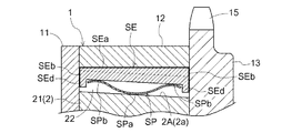
As shown in FIGS. 2 and 3, a mounting groove 22 (protrusion) extending from the
シール部材SEは、取付溝22の形状に沿って、径方向に摺動可能な形状である。シール部材SEは、図4に示すごとく、摺接部SEaと、内部ロータ2の回転方向に沿う側壁部SEbと、内部ロータ2の厚み方向に沿う側壁部SEcと、脚部SEdとを備えている。摺接部SEaが外部ロータ12の内周面に対して摺接する。摺接部SEaは、円弧形状の断面形状となるよう形成してある。側壁部SEb,SEcは、摺接部SEaの四方周囲を垂直に立ち上げて箱形状に形成してある。脚部SEdは、フロントプレート11及びリアプレート13に接する周壁部SEbをさらに垂直に立ち上げて形成してある。以下、図4における摺接部SEaの長辺方向の寸法を「長さ」と称し、摺接部SEaの短辺方向の寸法を「幅」と称し、脚部SEdの立上り方向の寸法を「高さ」と称する。
The seal member SE has a shape that can slide in the radial direction along the shape of the mounting
付勢部材SPは、例えば、図3、図4に示すごとく、円弧形状に湾曲した板ばねであって、中央部SPaが取付溝22に向けて湾曲し、両端部SPb,SPbがシール部材SEに向けて湾曲する。こうして、付勢部材SPは、弾性変形により付勢力を発揮する。
The urging member SP is, for example, a leaf spring that is curved in an arc shape as shown in FIGS. 3 and 4, the central portion SPa is curved toward the mounting
図3に示すように、シール部材SEは、付勢部材SPで付勢されて、外部ロータ12の抜きテーパ12aの傾斜面12Aに対して、摺接部SEaが当接し、シール部材SEの側壁部SEbとフロントプレート11及びリアプレート13との間には多少の隙間が生じることとなる。
As shown in FIG. 3, the seal member SE is urged by the urging member SP, and the sliding contact portion SEa comes into contact with the
本実施形態では、抜きテーパ12aの傾斜面12Aに対し、付勢部材SPがシール部材SEのフロントプレート11寄りの部分と、リアプレート13寄りの部分を共に押圧し、シール部材SEを外部ロータ12の側に付勢するよう構成されている。すなわち、付勢部材SPが、抜きテーパ12aの傾斜を結果的に吸収している。
In the present embodiment, the biasing member SP presses both the portion of the seal member SE near the
〔第2実施形態〕
シール部材SEと付勢部材SPとの構成は、上述の実施形態に限られるものではない。別の実施形態を図面に基づいて説明する。上述の実施形態と同様の構成に関する説明は省略する。また、同じ構成の箇所には同じ符号を付すこととする。
[Second Embodiment]
The configuration of the seal member SE and the biasing member SP is not limited to the above-described embodiment. Another embodiment will be described with reference to the drawings. A description of the same configuration as that of the above-described embodiment is omitted. In addition, the same reference numerals are assigned to the same components.
例えば、図5に示すごとく、シール部材SEと、フロントプレート11及びリアプレート13との間に隙間が生じないように、シール部材SEの摺接部SEaが抜きテーパ12aの傾斜面12Aに当接する状態において、シール部材SEの側壁部SEbとフロントプレート11及びリアプレート13とが完全に接するよう構成してもよい。こうすると、シール部材SEによる進角室41と遅角室42との間の密閉度が向上する。
For example, as shown in FIG. 5, the sliding contact portion SEa of the seal member SE abuts on the
〔第3実施形態〕
例えば、図6に示すごとく、シール部材SEの形状を、外部ロータ12の抜きテーパ12aの傾斜面12Aに対向する面を、その傾斜面12Aと平行に形成し、内部ロータ2の内周面に対向する面は、傾斜のない当該内周面と平行に形成してもよい。こうすると、シール部材SEによって、外部ロータ12の抜きテーパ12aの傾斜が吸収され、確実に気密性が確保される。このとき、付勢部材SPは、外部ロータ12の厚み方向において、シール部材SEの抜けテーパ12aが広がる側(フロントプレート11の側)と、抜けテーパ12aが窄まる側(リアプレート13の側)とをほぼ均等に押圧することになる。
[Third Embodiment]
For example, as shown in FIG. 6, the shape of the seal member SE is formed such that the surface facing the
〔第4実施形態〕
内部ロータ2をダイキャストにより製造し、抜きテーパ2aが内部ロータ2の外周面に形成された場合の実施形態を図7に示す。抜きテーパ2aは、リアプレート13に向けて窄まるよう形成されている。本実施形態では、シール部材SEは通常のものであり、シール部材SEの摺接部SEaは外部ロータ12の内周面に密接し、フロントプレート11及びリアプレート13とも隙間なく接する。付勢部材SPは、シール部材SEのフロントプレート11の側と、リアプレート13の側とを押圧するよう構成されており、リアプレート13の側の方がフロントプレート11の側より径方向に付勢する領域が大きい。つまり、付勢部材SPが、結果的に内部ロータ2の抜きテーパ2aの傾斜を吸収している。
[Fourth Embodiment]
FIG. 7 shows an embodiment in which the
〔第5実施形態〕
図8に示すごとく、シール部材SEは、内部ロータ2の抜きテーパ2aに対向する面が抜きテーパ2aの傾斜面2Aに平行に形成されている。その結果、付勢部材SPがシール部材SEを付勢する径方向の領域は、内部ロータ2の厚み方向において略一定となり、シール部材SEが抜きテーパ2aの傾斜を吸収する。したがって、付勢部材SPは、シール部材SEのフロントプレート11の側と、リアプレート13の側とを略同じ付勢力で付勢することとなる。
[Fifth Embodiment]
As shown in FIG. 8, the seal member SE has a surface facing the
〔第6実施形態〕
図9に示すごとく、内部ロータ2の外周面及び外部ロータ12の内周面に抜きテーパ2a,12aが形成されており、抜きテーパ2の傾斜面2Aと抜きテーパ12aの傾斜面12Aとが平行になるよう形成されている。この場合、外部ロータ12と内部ロータ2に挟まれた取付溝22において、内部ロータ2の厚み方向において、径方向への間隔がほぼ一定になる。したがって、シール部材SE、付勢部材SPは、抜きテーパ2a,12aの傾斜の影響をそれほど受けず、共に通常のものを用いることができる。
[Sixth Embodiment]
As shown in FIG. 9, the
〔第7実施形態〕
本実施形態においても、内部ロータ2の外周面及び外部ロータ12の内周面に抜きテーパ2a,12aが形成されており、抜きテーパ2の傾斜面2Aと抜きテーパ12aの傾斜面12Aとが平行になるよう形成されている。この場合に、図10に示すごとく、シール部材SEの側壁部SEbと、フロントプレート11及びリアプレート13との間に隙間が生じないように、シール部材SEの摺接部SEaが抜きテーパ12aの傾斜面12Aに当接する状態において、シール部材SEの側壁部SEbとフロントプレート11及びリアプレート13とが完全に接するよう構成してもよい。こうすると、シール部材SEによる進角室41と遅角室42との間の密閉度が向上する。
[Seventh Embodiment]
Also in this embodiment, the
〔第8実施形態〕
外部ロータ12の内周面に形成された抜きテーパ12aに対し、シール部材SEが当接し、このシール部材SEを付勢部材SPによって付勢する場合、抜きテーパ12aの傾斜の影響を受けて、シール部材SEが外部ロータ12の厚み方向において抜きテーパ12aが拡がる方向(フロントプレート11の側)に移動し易い。
[Eighth Embodiment]
When the seal member SE abuts against the
そこで、図11に示すごとく、内部ロータ2の取付溝22において、抜きテーパ12aが窄まる方向(リアプレート13の側)に、シール部材SEの脚部SEdが係合する係合凹部22aが形成されている。シール部材SEの脚部SEdが、係合凹部22aと係合した状態で付勢部材SPによって抜きテーパ12aに向けて付勢されていると、シール部材SEの抜きテーパ12aが拡がる方向(フロントプレート11の側)へのずれが抑制され、結果的に、シール部材SEの摺接部SEaが抜きテーパ12aの傾斜面12Aを安定的に密閉することとなる。
Therefore, as shown in FIG. 11, in the mounting
〔第9実施形態〕
図12に示すごとく、シール部材SEは、抜きテーパ12aの傾斜面12Aに対向する摺接部SEaを抜きテーパ12aの傾斜面12Aに平行に形成し、付勢部材SPを受ける面は抜きテーパ12aの窄まる方向への傾斜よりも大きく傾斜させて形成する。このようにすると、付勢部材SPは、シール部材SEを抜きテーパ12aの傾斜面12Aに対して垂直方向から窄まる側(図面右側)に向けて付勢する。すなわち、付勢部材SPは、シール部材SEを外部ロータ12に向けて付勢するとともに、抜きテーパ12aが窄まる方向(リアプレート13の側)に付勢する。一方、外部ロータ12の回転により遠心力が働き、シール部材SEは抜きテーパ12aの傾斜に沿って抜きテーパ12aの拡がる方向に移動しようとする。しかし、遠心力によってシール部材SEが抜きテーパ12aの拡がる方向に移動しようとする力は、付勢部材SPがシール部材SEを抜きテーパ12aが窄まる方向に付勢する力によって相殺される。その結果、外部ロータ12の回転時に遠心力が働いても、シール部材SEは内部ロータ2の径方向に向けて均等に付勢されることなり、気密性が確保される。
[Ninth Embodiment]
As shown in FIG. 12, in the seal member SE, the sliding contact part SEa facing the
〔第10実施形態〕
図13に示すごとく、内部ロータ2の外周面に径方向に突出し、付勢部材SPが当接する当接部2bが形成されている。そして、付勢部材SPは、シール部材SEを外部ロータ12に向けて付勢するとともに、当接部2bからシール部材SEの脚部SEdを抜きテーパ12aが窄まる方向(リアプレート13の側)に付勢するよう構成されている。こうすることで、シール部材SEの抜きテーパ12aが拡がる方向(フロントプレート11の側)へのずれが抑制され、結果的に、シール部材SEの摺接部SEaが抜きテーパ12aの傾斜面12Aを安定的に密閉することとなる。
[Tenth embodiment]
As shown in FIG. 13, a
〔第11実施形態〕
図14に示すごとく、シール部材SEのフロントプレート11及びリアプレート13に対向する周壁部SEbの角部に、面取り部SEeが形成されている。弁開閉時期制御装置には、ハウジング1に対して内部ロータ2が相対回転移動すべく、エンジンオイルが用いられている。エンジンオイルは、エンジンの内部の摺動部分の潤滑油として用いられ、摺動部分から微小ながら異物(スラッジ、鉄粉等)が発生する。この異物がシール部材SEとハウジング1(もしくは、シール部材SEと内部ロータ2)の間に介在し、相対回転時に異物が研磨剤として作用してハウジング1(もしくは内部ロータ2)が磨耗することが考えられる。
[Eleventh embodiment]
As shown in FIG. 14, chamfered portions SEe are formed at corners of the peripheral wall portion SEb facing the
ここで、前述の面取り部SEeが形成されていると、面取り部SEeが進角室41と遅角室42との間の通路となり、微小なオイル漏れを許容し、シール部材SEとハウジング1(もしくは、シール部材SEと内部ロータ2)の間に介在する異物を、進角室41もしくは遅角室42に排出できる。こうして、シール部材SEに面取り部SEeが形成されることで、ハウジング1(もしくは内部ロータ2)の磨耗を抑制できる。
なお、この進角室41と遅角室42との間の、微小なオイル漏れを許容する通路は、シール部材SEの面取り部に限らず、摺接部SEaに溝として設けてもよい。
Here, when the chamfered portion SEe is formed, the chamfered portion SEe serves as a passage between the
The passage between the
図14では、面取り部SEeが、フロントプレート11及びリアプレート13と対向する面の角部においてL字状に形成されているが、面取り部SEeの形状はこれに限定されない。面取り部SEeは、例えば、単に斜めに切除されて形成されていてもよく、面取り部SEeが進角室41と遅角室42との間の通路となる形状であればよい。
In FIG. 14, the chamfered portion SEe is formed in an L shape at the corner portion of the surface facing the
〔その他の実施形態〕
上述の実施形態において、仕切部として突出部21を内部ロータ2に形成したが、これに限られるものではない。例えば、図示はしないが、内部ロータ2にベーン溝を形成し、ベーン溝に仕切部としてのプレート形状のベーンを配設した構成であっても良い。この場合、ベーン自体が外部ロータ12の側に付勢され、シール部材としての役割をなす。よって、外部ロータ12の側の仕切部としての突出部14にのみ、本発明に係るシール部材及び付勢部材を配設する構成とする。
[Other Embodiments]
In the above-mentioned embodiment, although the
上述の実施形態において、外部ロータ12及び内部ロータ2の突出部14,21に取付溝を形成し、この取付溝にシール部材SEを配設したが、外部ロータ12及び内部ロータ2の突出部14,21に対向する内部ロータ2また外部ロータ12に取付溝を形成し、この溝部にシール部材SEを配設してもよい。
In the above-described embodiment, the mounting grooves are formed in the
なお、本発明は、弁開閉時期制御装置のうち、シール部材及び付勢部材の構成に特徴を有するものであるため、その他の構成は上述の構成に限定されるものではない。例えば、本発明に係るシール部材及び付勢部材を排気弁側の弁開閉時期制御装置に本発明を適用しても良い。また、ロック機構を備えていなくても、あるいはロック機構の構成が異なっていても良い。 In addition, since this invention has the characteristics in the structure of a sealing member and a biasing member among valve | bulb opening / closing timing control apparatuses, other structures are not limited to the above-mentioned structure. For example, the present invention may be applied to the valve opening / closing timing control device on the exhaust valve side of the sealing member and the biasing member according to the present invention. Further, the lock mechanism may not be provided, or the structure of the lock mechanism may be different.
さらに、上述の実施形態では、付勢部材SPを板バネで構成したが、これに限られるものではない。例えば、図示はしないが、付勢部材SPを線バネや、線バネと板バネとの混合部材で構成してもよいし、コイルバネで構成してもよい。 Furthermore, in the above-described embodiment, the urging member SP is configured by a leaf spring, but is not limited thereto. For example, although not illustrated, the urging member SP may be constituted by a wire spring, a mixed member of a wire spring and a leaf spring, or a coil spring.
本発明は、自動車その他の内燃機関の弁開閉時期制御装置に利用することができる。 The present invention can be used for a valve opening / closing timing control device of an automobile or other internal combustion engine.
1 ハウジング(駆動側回転部材)
2 内部ロータ(従動側回転部材)
2a 抜きテーパ
2A 傾斜面
2b 当接部
4 流体圧室
11 フロントプレート(第1プレート)
12 外部ロータ
12a 抜きテーパ
12A 傾斜面
13 リアプレート(第2プレート)
14 突出部(仕切部)
21 突出部(仕切部)
41 進角室
42 遅角室
SE シール部材
SEa 摺接部
SEb 側壁部
SEd 脚部
SEe 面取り部
SP 付勢部材
1 Housing (drive side rotating member)
2 Internal rotor (driven side rotating member)
11 Front plate (first plate)
12
13 Rear plate (second plate)
14 Projection (partition)
21 Projection (partition)
41
Claims (5)
前記駆動側回転体に対して同軸上に配置され、内燃機関の弁開閉用のカムシャフトに同期回転する従動側回転体と、
前記駆動側回転体と前記従動側回転体とで形成された流体圧室を遅角室と進角室とに仕切るよう前記駆動側回転体及び前記従動側回転体の少なくとも一方に設けられた仕切部と、
前記仕切部のうち前記駆動側回転体もしくは前記従動側回転体に対向する位置、または、前記駆動側回転体もしくは前記従動側回転体のうち前記仕切部に対向する位置に配設されて、前記駆動側回転体と前記従動側回転体との相対回転に基づく前記遅角室と前記進角室との間での作動流体の漏洩を防止するシール部材と、
弾性変形に基づく付勢力によって、前記シール部材を前記仕切部の側から前記駆動側回転体もしくは前記従動側回転体の側へ、または、前記シール部材を前記駆動側回転体もしくは前記従動側回転体の側から前記仕切部の側へ付勢する付勢部材と、を備え、
前記駆動側回転体は、前記カムシャフトに接続される側とは反対側に設けられる第1プレートと、前記カムシャフトに接続される側に設けられる第2プレートと、を備え、
前記駆動側回転体をダイキャストで製造し、当該ダイキャストで製造された回転体のうち前記仕切部及び前記仕切部に対向する面の少なくとも何れか一方が抜きテーパの傾斜面で構成され、
前記抜きテーパの傾斜面に当接するよう配設された前記シール部材は、前記第1プレート及び前記第2プレートに密接するよう、前記第1プレートに接触する面と前記傾斜面に当接する対向面とがなす角度、及び、前記第2プレートに接触する面と前記傾斜面に当接する対向面とがなす角度のうち、一方を鋭角とし、他方を鈍角とした弁開閉時期制御装置。 A drive-side rotating body that rotates synchronously with the crankshaft;
A driven-side rotator that is coaxially disposed with respect to the drive-side rotator and rotates synchronously with a camshaft for opening and closing a valve of an internal combustion engine;
A partition provided on at least one of the driving side rotating body and the driven side rotating body so as to partition a fluid pressure chamber formed by the driving side rotating body and the driven side rotating body into a retard chamber and an advance chamber. And
The partition portion is disposed at a position facing the driving side rotating body or the driven side rotating body, or at a position facing the partition portion among the driving side rotating body or the driven side rotating body, and A seal member for preventing leakage of the working fluid between the retard chamber and the advance chamber based on relative rotation between the drive side rotor and the driven side rotor;
By means of an urging force based on elastic deformation, the seal member is moved from the partition portion side to the driving side rotating body or the driven side rotating body, or the sealing member is moved to the driving side rotating body or the driven side rotating body. An urging member for urging from the side toward the partitioning portion,
The drive-side rotator includes a first plate provided on a side opposite to a side connected to the camshaft, and a second plate provided on a side connected to the camshaft,
The drive-side rotating body is manufactured by die casting, and at least one of the partition portion and the surface facing the partition portion of the rotating body manufactured by the die casting is configured with an inclined surface with a tapered taper,
The seal member disposed so as to contact the inclined surface of the taper taper has a surface contacting the first plate and a facing surface contacting the inclined surface so as to be in close contact with the first plate and the second plate. And a valve opening / closing timing control device in which one of the angle formed by the surface contacting the second plate and the facing surface contacting the inclined surface is an acute angle and the other is an obtuse angle.
前記駆動側回転体もしくは前記従動側回転体における前記仕切部に対向する位置、及び、前記仕切部における前記駆動側回転体もしくは前記従動側回転体に対向する位置のいずれもが前記抜きテーパの傾斜面で構成された請求項1記載の弁開閉時期制御装置。 The opposite inclined surface is formed in parallel to one inclined surface of the draft taper formed on the driving side rotating body and the driven side rotating body,
The position of the drive-side rotator or the driven-side rotator facing the partitioning part and the position of the partitioning part facing the drive-side rotator or the driven-side rotator are both inclined by the draft taper. The valve opening / closing timing control device according to claim 1, wherein the valve opening / closing timing control device is constituted by a surface.
Priority Applications (4)
| Application Number | Priority Date | Filing Date | Title |
|---|---|---|---|
| JP2010155998A JP5585827B2 (en) | 2010-07-08 | 2010-07-08 | Valve timing control device |
| EP11170626.3A EP2405107B1 (en) | 2010-07-08 | 2011-06-20 | Variable valve timing control apparatus |
| US13/163,911 US8544433B2 (en) | 2010-07-08 | 2011-06-20 | Variable valve timing control apparatus |
| CN201110192874.8A CN102312689B (en) | 2010-07-08 | 2011-07-06 | Variable valve timing control apparatus |
Applications Claiming Priority (1)
| Application Number | Priority Date | Filing Date | Title |
|---|---|---|---|
| JP2010155998A JP5585827B2 (en) | 2010-07-08 | 2010-07-08 | Valve timing control device |
Publications (2)
| Publication Number | Publication Date |
|---|---|
| JP2012017702A JP2012017702A (en) | 2012-01-26 |
| JP5585827B2 true JP5585827B2 (en) | 2014-09-10 |
Family
ID=44653118
Family Applications (1)
| Application Number | Title | Priority Date | Filing Date |
|---|---|---|---|
| JP2010155998A Expired - Fee Related JP5585827B2 (en) | 2010-07-08 | 2010-07-08 | Valve timing control device |
Country Status (4)
| Country | Link |
|---|---|
| US (1) | US8544433B2 (en) |
| EP (1) | EP2405107B1 (en) |
| JP (1) | JP5585827B2 (en) |
| CN (1) | CN102312689B (en) |
Families Citing this family (6)
| Publication number | Priority date | Publication date | Assignee | Title |
|---|---|---|---|---|
| US9303536B2 (en) * | 2011-11-04 | 2016-04-05 | Aisin Seiki Kabushiki Kaisha | Valve opening and closing control apparatus |
| US9874156B2 (en) * | 2013-07-31 | 2018-01-23 | Aisin Seiki Kabushiki Kaisha | Control device for internal combustion engine |
| DE102014208598B4 (en) * | 2014-05-08 | 2020-10-29 | Schaeffler Technologies AG & Co. KG | Camshaft adjuster with a hydraulic chamber sealing element that can be switched back and forth to achieve a hydraulic freewheel |
| CN106285815A (en) * | 2015-05-13 | 2017-01-04 | 舍弗勒技术股份两合公司 | Camshaft adjuster |
| JP6672749B2 (en) * | 2015-12-02 | 2020-03-25 | アイシン精機株式会社 | Valve timing control device |
| SE541427C2 (en) * | 2018-08-08 | 2019-10-01 | C Falk Remote Control Ab | Torque-limiting clutch comprising an electric control system |
Family Cites Families (21)
| Publication number | Priority date | Publication date | Assignee | Title |
|---|---|---|---|---|
| US5107804A (en) * | 1989-10-16 | 1992-04-28 | Borg-Warner Automotive Transmission & Engine Components Corporation | Variable camshaft timing for internal combustion engine |
| US5666914A (en) * | 1994-05-13 | 1997-09-16 | Nippondenso Co., Ltd. | Vane type angular phase adjusting device |
| US6012419A (en) * | 1996-08-09 | 2000-01-11 | Denso Corporation | Rotational phase adjusting apparatus having seat for drill-machining |
| JP3711872B2 (en) * | 1996-09-13 | 2005-11-02 | 株式会社デンソー | Valve timing adjusting device for internal combustion engine |
| JP3191865B2 (en) * | 1996-09-13 | 2001-07-23 | 株式会社デンソー | Valve timing adjustment device for internal combustion engine |
| JP3196696B2 (en) * | 1997-08-25 | 2001-08-06 | 株式会社デンソー | Valve timing adjustment device |
| JPH11280426A (en) * | 1998-03-31 | 1999-10-12 | Denso Corp | Valve timing adjusting device |
| JP3385967B2 (en) * | 1998-04-27 | 2003-03-10 | トヨタ自動車株式会社 | Housing for variable rotation phase difference device, rotor for variable rotation phase difference device, variable rotation phase difference device |
| JP2000038909A (en) * | 1998-07-22 | 2000-02-08 | Mitsubishi Electric Corp | Variable valve timing device |
| JP2001193421A (en) | 1999-10-25 | 2001-07-17 | Mitsubishi Electric Corp | Valve-timing regulator |
| JP2001132415A (en) | 1999-10-29 | 2001-05-15 | Ntn Corp | Valve timing regulating device for engine |
| JP2001207812A (en) * | 2000-01-25 | 2001-08-03 | Unisia Jecs Corp | Valve timing device for internal combustion engine |
| JP3771412B2 (en) * | 2000-02-04 | 2006-04-26 | トヨタ自動車株式会社 | Rotational phase difference variable mechanism and manufacturing method thereof |
| JP4309011B2 (en) * | 2000-02-28 | 2009-08-05 | 三菱電機株式会社 | Valve timing variable device |
| JP4218199B2 (en) * | 2000-09-22 | 2009-02-04 | 三菱電機株式会社 | Valve timing adjustment device |
| JP2002180809A (en) * | 2000-10-04 | 2002-06-26 | Denso Corp | Method of manufacturing valve timing adjusting device |
| JP2002295212A (en) * | 2001-03-30 | 2002-10-09 | Denso Corp | Valve timing adjusting apparatus and method of producing the same |
| JP2003003808A (en) * | 2001-06-25 | 2003-01-08 | Hitachi Unisia Automotive Ltd | Valve timing controller for internal combustion engine |
| DE10211607A1 (en) * | 2002-03-12 | 2003-10-09 | Porsche Ag | Drive for valve train controls of vehicles, preferably of camshaft adjusters |
| US20090017920A1 (en) * | 2007-07-13 | 2009-01-15 | Fox Michael J | Front cover for a vane-type cam phaser |
| JP2009068448A (en) * | 2007-09-14 | 2009-04-02 | Denso Corp | Valve timing adjusting device |
-
2010
- 2010-07-08 JP JP2010155998A patent/JP5585827B2/en not_active Expired - Fee Related
-
2011
- 2011-06-20 US US13/163,911 patent/US8544433B2/en not_active Expired - Fee Related
- 2011-06-20 EP EP11170626.3A patent/EP2405107B1/en not_active Not-in-force
- 2011-07-06 CN CN201110192874.8A patent/CN102312689B/en not_active Expired - Fee Related
Also Published As
| Publication number | Publication date |
|---|---|
| EP2405107A3 (en) | 2012-03-28 |
| EP2405107B1 (en) | 2013-06-12 |
| EP2405107A2 (en) | 2012-01-11 |
| CN102312689B (en) | 2014-08-13 |
| CN102312689A (en) | 2012-01-11 |
| JP2012017702A (en) | 2012-01-26 |
| US8544433B2 (en) | 2013-10-01 |
| US20120006290A1 (en) | 2012-01-12 |
Similar Documents
| Publication | Publication Date | Title |
|---|---|---|
| JP5585827B2 (en) | Valve timing control device | |
| EP2711511A2 (en) | Zentriernut für einen Verbrennungsmotor | |
| JP2009185719A (en) | Valve timing regulating device | |
| JP2009068448A (en) | Valve timing adjusting device | |
| JP2010196674A (en) | Valve timing control device for internal combustion engine | |
| JP5850280B2 (en) | Valve timing adjustment device | |
| JP2009138599A (en) | Valve timing adjusting device | |
| JP2009215881A (en) | Valve timing adjustment device | |
| US6439183B1 (en) | Valve timing adjusting device | |
| JP6312568B2 (en) | Valve timing control device for internal combustion engine | |
| US6935291B2 (en) | Variable valve timing controller | |
| CN104929714B (en) | Valve timing controller | |
| JP6775032B2 (en) | Hydraulic control valve and valve timing control device for internal combustion engine | |
| JP6443294B2 (en) | Valve timing adjustment device | |
| JP6422829B2 (en) | Valve timing control device for internal combustion engine | |
| JP3899616B2 (en) | Valve timing adjusting device for internal combustion engine | |
| JP2009209821A (en) | Valve-timing regulator | |
| JP2003106113A (en) | Valve timing control device of internal combustion engine | |
| US10337358B2 (en) | Valve timing control apparatus for internal combustion engine | |
| WO2021125073A1 (en) | Internal combustion engine valve timing control device | |
| JP6131665B2 (en) | Valve timing control device | |
| JP2016183561A (en) | Valve timing adjusting device | |
| JPH09303119A (en) | Valve timing varying device for internal combustion engine | |
| JP2000213309A (en) | Valve timing adjusting device | |
| JP2021017808A (en) | Valve timing adjustment device |
Legal Events
| Date | Code | Title | Description |
|---|---|---|---|
| A621 | Written request for application examination |
Free format text: JAPANESE INTERMEDIATE CODE: A621 Effective date: 20130613 |
|
| A977 | Report on retrieval |
Free format text: JAPANESE INTERMEDIATE CODE: A971007 Effective date: 20140320 |
|
| A131 | Notification of reasons for refusal |
Free format text: JAPANESE INTERMEDIATE CODE: A131 Effective date: 20140403 |
|
| A521 | Written amendment |
Free format text: JAPANESE INTERMEDIATE CODE: A523 Effective date: 20140529 |
|
| TRDD | Decision of grant or rejection written | ||
| A01 | Written decision to grant a patent or to grant a registration (utility model) |
Free format text: JAPANESE INTERMEDIATE CODE: A01 Effective date: 20140626 |
|
| A61 | First payment of annual fees (during grant procedure) |
Free format text: JAPANESE INTERMEDIATE CODE: A61 Effective date: 20140709 |
|
| R151 | Written notification of patent or utility model registration |
Ref document number: 5585827 Country of ref document: JP Free format text: JAPANESE INTERMEDIATE CODE: R151 |
|
| LAPS | Cancellation because of no payment of annual fees |