JP5583812B2 - Method and system for power control in a communication system - Google Patents
Method and system for power control in a communication system Download PDFInfo
- Publication number
- JP5583812B2 JP5583812B2 JP2013083339A JP2013083339A JP5583812B2 JP 5583812 B2 JP5583812 B2 JP 5583812B2 JP 2013083339 A JP2013083339 A JP 2013083339A JP 2013083339 A JP2013083339 A JP 2013083339A JP 5583812 B2 JP5583812 B2 JP 5583812B2
- Authority
- JP
- Japan
- Prior art keywords
- snr
- signal
- power
- transmitted
- data rate
- Prior art date
- Legal status (The legal status is an assumption and is not a legal conclusion. Google has not performed a legal analysis and makes no representation as to the accuracy of the status listed.)
- Expired - Fee Related
Links
Images


Classifications
-
- H—ELECTRICITY
- H04—ELECTRIC COMMUNICATION TECHNIQUE
- H04W—WIRELESS COMMUNICATION NETWORKS
- H04W52/00—Power management, e.g. TPC [Transmission Power Control], power saving or power classes
- H04W52/04—TPC
- H04W52/18—TPC being performed according to specific parameters
- H04W52/26—TPC being performed according to specific parameters using transmission rate or quality of service QoS [Quality of Service]
- H04W52/267—TPC being performed according to specific parameters using transmission rate or quality of service QoS [Quality of Service] taking into account the information rate
Description
この発明は一般に無線通信に関し、特に符号分割多元接続(CDMA)システムのようなセルラー通信システムにおける電力制御に関する。 The present invention relates generally to wireless communications, and more particularly to power control in cellular communication systems such as code division multiple access (CDMA) systems.
符号分割多元接続(CDMA)技術は無線システム上の多重化データに対してスペクトル的に効率的な解決法を提供する。これらのシステムは携帯電話ネットワーク、無線電話システム、パーソナル通信システム(PCS)および同類のものを含むことができる。 Code division multiple access (CDMA) technology provides a spectrally efficient solution for multiplexed data on wireless systems. These systems can include cellular telephone networks, wireless telephone systems, personal communication systems (PCS) and the like.
比較的に高速な電力制御ループは典型的にCDMAシステムにより採用される。 A relatively fast power control loop is typically employed by CDMA systems.
電力制御は、異種の信号が互いに干渉するのを防止するためにおよび信号対干渉プラス雑音比、以下信号対雑音比(SNR)を所望の範囲内に維持するために使用される。 Power control is used to prevent heterogeneous signals from interfering with each other and to maintain a signal to interference plus noise ratio, hereinafter signal to noise ratio (SNR), within a desired range.
効率的な方法でスペクトル帯域幅を使用するために、可変データレートで通信することができ、データレートにおける調節を用いて送信電力を調節することが望ましい。これはスペクトル帯域幅をより効率的に使用し、また電池式のステーションのバッテリ寿命をさらによくする。しかしながら、従来の受信機は、データレートの変化による送信電力に対する意図的な調節と、レイリーフェージングとして知られる建設的および破壊的マルチパス干渉の影響のような経路損失又は環境条件による受信電力の変化とを区別することができない。 In order to use spectral bandwidth in an efficient manner, it is possible to communicate at a variable data rate and it is desirable to adjust the transmit power with adjustments in the data rate. This uses spectral bandwidth more efficiently and further improves battery life for battery powered stations. However, conventional receivers do not intentionally adjust transmit power due to data rate changes, and receive power changes due to path loss or environmental conditions such as the effects of constructive and destructive multipath interference known as Rayleigh fading. Can not be distinguished.
35U.S.C.§119に基づく優先権主張
この特許出願は、この特許出願の譲受人に譲渡され参照することにより本明細書に組み込まれる、2004年9月24日に出願の「時間分割デュプレックス通信システムにおける電力制御のための方法および装置」(METHOD AND APPARATUS FRO POWER CONTROL IN TIME DIVISION DUPLEX COMMUNICATIONS SYSTEMS)というタイトルの米国仮出願番号第60/612、834に対する優先権を主張する。
35U. S. C. This patent application is assigned to “Power Control in Time Division Duplex Communication System” filed on Sep. 24, 2004, assigned to the assignee of this patent application and incorporated herein by reference. Claims priority to US Provisional Application No. 60 / 612,834 entitled “METHOD AND APPARATUS FRO POWER CONTROL IN TIME DIVISION DUPLEX COMMUNICATIONS SYSTEMS”.
1つの観点は無線通信システムのための装置である。この装置は、少なくとも第1のデータレートとこの第1のデータレート以外の第2のデータレートを有する送信機から送信された信号を受信するように構成された受信機であって、第2のデータレートのための送信された信号の送信された電力が第1のデータレートのための送信された電力に対するオフセット量により調節可能である、受信機と、前記送信された信号に関連する基準信号特性を決定するように構成された受信機回路と、前記基準信号特性を目標値と比較し、少なくとも一部分前記比較と、前記送信された信号により提供される情報に基づいて電力制御コマンドを発生するように構成された処理回路と、を含む。 One aspect is an apparatus for a wireless communication system. The apparatus is a receiver configured to receive a signal transmitted from a transmitter having at least a first data rate and a second data rate other than the first data rate, the second data rate being A receiver, wherein the transmitted power of the transmitted signal for the data rate is adjustable by an offset amount relative to the transmitted power for the first data rate, and a reference signal associated with the transmitted signal A receiver circuit configured to determine a characteristic; comparing the reference signal characteristic with a target value; and generating a power control command based at least in part on the comparison and information provided by the transmitted signal And a processing circuit configured as described above.
1つの観点は無線通信システムにおいて電力を制御する方法である。この方法は、
送信機から、少なくとも第1のデータレートと、第1のデータレート以外の第2のデータレートを有する送信された信号を受信することであって、第2のデータレートのための送信された信号の送信された電力は、第1のデータレートのための送信された電力に対するオフセット値により調節可能であることと、送信された信号に関連する基準信号特性を決定することと、基準信号特性を目標値と比較することと、少なくとも一部分前記比較および前記送信された信号により提供される情報に基づいて電力制御コマンドを発生することと、を含む。
One aspect is a method for controlling power in a wireless communication system. This method
Receiving a transmitted signal from a transmitter having at least a first data rate and a second data rate other than the first data rate, the transmitted signal for the second data rate The transmitted power of the first data rate is adjustable by an offset value relative to the transmitted power, determining a reference signal characteristic associated with the transmitted signal, and determining a reference signal characteristic Comparing to a target value and generating a power control command based at least in part on the comparison and information provided by the transmitted signal.
1つの観点は基準信号特性を決定する方法である。この方法は、受信された信号の信号特性を決定することと、コードレートの調節による電力の調節を補償するためにオフセット値を用いて信号特性を調節することと、電力制御のために、調節された信号特性を使用することと、を含む。 One aspect is a method for determining reference signal characteristics. This method determines the signal characteristics of the received signal, adjusts the signal characteristics using an offset value to compensate for the power adjustment by adjusting the code rate, and adjusts for power control. Using the measured signal characteristics.
1つの観点は信号特性を決定する方法である。この方法は、受信された信号の信号特性を決定することと、データレートの変化からチャネル条件により信号特性の第1の成分を分離し電力調節により第2の成分を分離することと、電力制御のために前記信号特性の第1の成分を使用することと、を含む。 One aspect is a method for determining signal characteristics. The method determines a signal characteristic of a received signal, separates a first component of the signal characteristic from a change in data rate according to channel conditions and separates a second component by power adjustment, and power control. Using a first component of the signal characteristic for
1つの観点は無線通信システムにおいて電力を制御する方法を実行するためのコンピューター実行可能な命令を有するコンピューター読み取り可能媒体である。前記方法は、送信機から少なくとも第1のデータレートと、第1のデータレート以外の第2のデータレートを有する送信された信号を受信することであって、第2のデータレートのための送信された信号の送信された電力は第1のデータレートのための送信された電力に対するオフセット値により調節可能であることと、送信された信号に関連する基準信号特性を決定することと、基準信号特性を目標値と比較することと、少なくとも一部分前記比較、および送信された信号により提供される情報に基づいて電力制御コマンドを発生することと、を含む。 One aspect is a computer-readable medium having computer-executable instructions for performing a method of controlling power in a wireless communication system. The method includes receiving a transmitted signal having at least a first data rate and a second data rate other than the first data rate from a transmitter, wherein the transmission is for a second data rate. The transmitted power of the transmitted signal is adjustable by an offset value relative to the transmitted power for the first data rate, determining a reference signal characteristic associated with the transmitted signal, and a reference signal Comparing the characteristic to a target value and generating a power control command based at least in part on the comparison and information provided by the transmitted signal.
1つの観点は、基準信号特性を決定する方法を実行するコンピューター実行可能な命令を有するコンピューター読み取り可能媒体である。前記方法は、受信した信号の信号特性を決定することと、コードレートの調節により電力の調節を補償するためにオフセット値を用いて信号特性を調節することと、電力制御のために前記調節された信号特性を使用することと、を含む。 One aspect is a computer-readable medium having computer-executable instructions for performing a method for determining a reference signal characteristic. The method determines the signal characteristics of the received signal, adjusts the signal characteristics using an offset value to compensate for the power adjustment by adjusting the code rate, and is adjusted for power control. Using signal characteristics.
1つの観点は信号特性を決定する方法を実行するためのコンピューター実行可能な命令を有するコンピューター読み取り可能媒体である。前記方法は、受信した信号の信号特性を決定することと、データレートの変化からチャネル条件により信号特性の第1の成分を分離し、電力調節により第2の成分を分離することと、を含み電力制御のために信号特性の第1の成分を使用することをさらに備える。 One aspect is a computer-readable medium having computer-executable instructions for performing a method for determining signal characteristics. The method includes determining a signal characteristic of a received signal and separating a first component of the signal characteristic according to channel conditions from a change in data rate and separating a second component by power adjustment. Further comprising using a first component of the signal characteristic for power control.
1つの観点は無線通信システムの電力を制御する装置である。前記装置は、送信機から、少なくとも第1のデータレートと第1のデータレート以外の第2のデータレートを有する送信された信号を受信する手段であって、前記第2のデータレートのための送信された信号の送信された電力は第1のデータレートのための送信された電力に対するオフセット値により調節可能である、手段と、送信された信号に関連する基準信号特性を決定する手段と、基準信号特性を目標値と比較する手段と、少なくとも一部分前記比較および送信された信号により提供される情報に基づいて電力制御コマンドを発生する手段と、を含む。 One aspect is an apparatus that controls the power of a wireless communication system. The apparatus is a means for receiving a transmitted signal having at least a first data rate and a second data rate other than the first data rate from a transmitter, the second data rate for the second data rate Means for adjusting the transmitted power of the transmitted signal by an offset value relative to the transmitted power for the first data rate; means for determining a reference signal characteristic associated with the transmitted signal; Means for comparing a reference signal characteristic with a target value; and means for generating a power control command based at least in part on information provided by the comparison and transmitted signal.
1つの観点は基準信号特性を決定する装置である。前記装置は、受信した信号の信号特性を決定する手段と、コードレートの調節により電力の調節を補償するためにオフセット値で信号特性を調節する手段と、電力制御ループにおいて前記調節された信号特性を使用する手段と、を含む。 One aspect is an apparatus for determining reference signal characteristics. The apparatus includes: means for determining a signal characteristic of a received signal; means for adjusting the signal characteristic with an offset value to compensate for power adjustment by adjusting a code rate; and the adjusted signal characteristic in a power control loop. Means for using.
1つの観点は信号特性を決定する装置である。この装置は、受信した信号の信号特性を決定する手段と、データレートの変化からチャネル条件により信号特性の第1の成分を分離し、電力調節により第2の成分を分離する手段と、電力制御のために信号特性の第1の成分を使用する手段と、を含む。 One aspect is an apparatus that determines signal characteristics. The apparatus includes means for determining a signal characteristic of a received signal, means for separating a first component of the signal characteristic from a change in data rate according to channel conditions, and separating a second component by power adjustment, and power control Using a first component of the signal characteristic for the purpose.
上述したように、この発明はCDMA技術を用いた通信システムのような無線通信システムに適用する。 As described above, the present invention is applied to a wireless communication system such as a communication system using CDMA technology.
当業者は、情報および信号はさまざまな異なる技術および技法のいずれかを用いて表してもよいことを理解するであろう。例えば、上述した記載全体にわたって参照されてもよいデータ、命令、コマンド、情報、信号、ビット、シンボルおよびチップは、電圧、電流、電磁波、磁界または磁性粒子、光学界または光学粒子、またはそれらの任意の組み合わせにより表されてもよい。 Those skilled in the art will appreciate that information and signals may be represented using any of a variety of different technologies and techniques. For example, data, instructions, commands, information, signals, bits, symbols and chips that may be referred to throughout the above description are voltages, currents, electromagnetic waves, magnetic fields or magnetic particles, optical fields or optical particles, or any of them May be represented by a combination of
当業者はさらに、ここに開示した実施の形態に関連して記載した種々の実例となる論理ブロック、モジュール、回路、およびアルゴリズムステップは、電子ハードウエア、コンピュータソフトウエアまたは両方の組合せで実施してもよいことを理解するであろう。 Those skilled in the art further understand that the various illustrative logic blocks, modules, circuits, and algorithm steps described in connection with the embodiments disclosed herein may be implemented in electronic hardware, computer software, or a combination of both. You will understand that.
このハードウエアとソフトウエアの互換性を明瞭に説明するために、種々の実例となる部品、ブロック、モジュール、回路、およびステップが一般にそれらの機能性の観点から上に記載された。そのような機能性がハードウエアまたはソフトウエアとして実現されるかは特定のアプリケーションおよび全体のシステムに課せられた設計制約に依存する。 To clearly illustrate this hardware and software compatibility, various illustrative components, blocks, modules, circuits, and steps have been generally described above in terms of their functionality. Whether such functionality is implemented as hardware or software depends upon the particular application and design constraints imposed on the overall system.
熟達した職人は、各特定のアプリケーションに対して記載した機能性を変形した方法で実施することができるが、そのような実施の判断は、この発明の範囲を逸脱するものとして解釈されるべきでない。 Expert craftsmen can implement the functionality described for each specific application in a modified manner, but such implementation judgment should not be construed as departing from the scope of the invention .
ここに開示された実施の形態に関連して記載された種々の実例となる論理ブロック、モジュール、および回路は、汎用プロセッサー、デジタルシグナルプロセッサ(DSP)、特定用途向け集積回路(ASIC)、フィールドプログラマブルゲートアレイ(FPGA)または他のプログラマブル論理装置、ディスクリートゲートまたはトランジスタロジック、ディスクリートハードウエアコンポーネント、またはここに記載した機能を実行するように設計されたいずれかの組合せを用いて実施または実行してもよい。汎用プロセッサーは、マイクロプロセッサーであってよいが、別の方法では、プロセッサーは、いずれかの一般的なプロセッサー、コントローラ、マイクロコントローラ、またはステートマシンであってよい。プロセッサーはまた、計算装置の組合せとしても実施できる。例えば、DSPとマイクロプロセッサーの組合せ、複数のマイクロプロセッサー、DSPコアと協力した1つ以上のマイクロプロセッサーまたはいずれかの他のそのような構成として実施してもよい。 ここに開示された実施の形態に関連して記載された方法またはアルゴリズムのステップは、ハードウエアにおいて、プロセッサーにより実行されるソフトウェアモジュールにおいて、または両者の組合せにおいて直接具現化してもよい。ソフトウェアモジュールはRAMメモリ、フラッシュメモリ、ROMメモリ、EPROMメモリ、EEPROMメモリ、レジスタ、ハードディスク、取り外し可能ディスク、CD-ROM、または技術的に既知である任意の他の形式の記憶媒体に常駐してよい。例示的な記憶媒体は、プロセッサーが記憶媒体から情報を読み取り、記憶媒体に情報を書き込むことができるようにプロセッサーに接続される。代替策では、記憶媒体はプロセッサーに一体化してよい。プロセッサー及び記憶媒体はASICに常駐してよい。ASICはユーザー端末に常駐してよい。代替策では、プロセッサー及び記憶媒体はユーザー端末内に別々の構成要素として常駐してよい。 Various illustrative logic blocks, modules, and circuits described in connection with the embodiments disclosed herein can be general purpose processors, digital signal processors (DSPs), application specific integrated circuits (ASICs), field programmable. Performed or performed using a gate array (FPGA) or other programmable logic device, discrete gate or transistor logic, discrete hardware components, or any combination designed to perform the functions described herein Good. A general purpose processor may be a microprocessor, but in the alternative, the processor may be any conventional processor, controller, microcontroller, or state machine. The processor can also be implemented as a combination of computing devices. For example, it may be implemented as a combination of a DSP and a microprocessor, multiple microprocessors, one or more microprocessors in cooperation with a DSP core, or any other such configuration. The method or algorithm steps described in connection with the embodiments disclosed herein may be implemented directly in hardware, in software modules executed by a processor, or in a combination of both. A software module may reside in RAM memory, flash memory, ROM memory, EPROM memory, EEPROM memory, registers, hard disk, removable disk, CD-ROM, or any other form of storage medium known in the art . An exemplary storage medium is coupled to the processor such that the processor can read information from, and write information to, the storage medium. In the alternative, the storage medium may be integral to the processor. The processor and the storage medium may reside in an ASIC. The ASIC may reside in the user terminal. In the alternative, the processor and the storage medium may reside as discrete components in a user terminal.
CDMA多重化の1つの利点はデータの拡散およびその後の逆拡散からの拡散利得である。これは、(逆拡散後に)受信したCDMA信号のSNRを増加させる。さらに、信号が拡散される前に、シンボルの送信において生じるエラーを訂正することができるように他のプロセスが典型的に適用される。例えば、これらのプロセスはビットインターリービング技術およびフォワードエラー訂正(FEC)技術を含む。フォワードエラー訂正技術の例は畳み込みコーディング、ターボコーディング、ブロックコーディング、および同類のものを含む。これらの技術は別個にまたは組み合わせて使用することができる。畳み込みコードにおいて、mのソースビットはnのコード化されたビットにコード化される。分数m/nはコードレートと呼ばれる。コード化された信号対非コード化された信号の信号対雑音比(SNR)の改良はコーディング利得と呼ばれる。これに関連して、非コード化信号は、フォワードエラー訂正スキームにより処理されなかったソースを指す。非コード化信号はそれ自体を圧縮オーディオ、ビデオまたはグラフィックデータのようなコード化されたデータの形式に一致させることができる。 One advantage of CDMA multiplexing is the spreading gain from data spreading and subsequent despreading. This increases the SNR of the received CDMA signal (after despreading). In addition, other processes are typically applied so that errors that occur in the transmission of symbols can be corrected before the signal is spread. For example, these processes include bit interleaving techniques and forward error correction (FEC) techniques. Examples of forward error correction techniques include convolutional coding, turbo coding, block coding, and the like. These techniques can be used separately or in combination. In a convolutional code, m source bits are encoded into n coded bits. The fraction m / n is called the code rate. The improvement in the signal-to-noise ratio (SNR) of a coded signal versus a non-coded signal is called coding gain. In this context, an uncoded signal refers to a source that has not been processed by a forward error correction scheme. The uncoded signal can itself conform to the form of coded data such as compressed audio, video or graphic data.
コーディング利得はコードレートに応じて変化する。コードレートm/nが相対的に高いとき、コーディング利得は相対的に小さい。コードレートm/nが相対的に低いとき、コーディング利得は相対的に高い。しかしながら、相対的に低いコードレートで、所定量の非コード化データに対して相対的により多くのコード化データが存在する。一実施形態において、非コード化信号がデータレートにおいて変化することができるとき、コーディングスキームにより使用されるコードレートは、低いコードレートが低いデータレートで使用され、高いコードレートが高いデータレートで使用されるように変化される。これは、使用されるコーディング利得における相対的差異により高いデータレートで送信されたデータに対して低いデータレートで送信されたデータのSNRを改善する。同じ全体的なSNRの場合、より低いデータレートを有する信号はより高いデータレートを有する信号よりも少ない電力で送信することができる。 The coding gain varies with the code rate. When the code rate m / n is relatively high, the coding gain is relatively small. When the code rate m / n is relatively low, the coding gain is relatively high. However, there is relatively more coded data for a given amount of uncoded data at a relatively low code rate. In one embodiment, when the uncoded signal can vary in data rate, the code rate used by the coding scheme is used at a lower data rate with a lower code rate and at a higher data rate with a higher code rate. To be changed. This improves the SNR of data transmitted at a lower data rate relative to data transmitted at a higher data rate due to the relative difference in coding gain used. For the same overall SNR, a signal with a lower data rate can be transmitted with less power than a signal with a higher data rate.
割り当てられたスペクトル帯域幅を効率的に使用することが望ましい。これは、限られた帯域幅上でより多くの通話のようなより多くのデータを通信可能にする。通信の多くの形式において、データは時間に対してレートにおいて変化することができる。例えば、ウェブを閲覧するユーザーは、ウェブページをダウンロードするために相対的に大きな量のデータを要求してもよいが、相対的に長い期間に対して別のウェブページを要求しないかもしれない。他の例は音声通信である。呼び出し側が話しをしているとき、電話ネットワークを介して転送されるデータ量は相対的に高い可能性がある。しかしながら、呼び出し側が沈黙しているとき、転送されるデータ量は相対的に低い可能性がありゼロに近づく可能性さえある。 It is desirable to use the allocated spectral bandwidth efficiently. This allows more data, such as more calls, to be communicated over the limited bandwidth. In many forms of communication, data can vary in rate over time. For example, a user browsing the web may require a relatively large amount of data to download a web page, but may not require another web page for a relatively long period of time. Another example is voice communication. When the caller is talking, the amount of data transferred over the telephone network can be relatively high. However, when the caller is silent, the amount of data transferred can be relatively low and can even approach zero.
スペクトル帯域幅を効率的に使用するために、可変データレートで通信することが望ましく、それに対応してデータを送信するために使用される送信電力を調節することが望ましい。スペクトル帯域幅の効率的な使用に加えて、送信電力を低減することは、携帯電話のような電池式のステーションのバッテリ寿命をさらによくすることができる。しかしながら、受信機が、データレートの変化による送信電力の意図的な調節と、レイリーフェージングとして知られる建設的および破壊的マルチパス干渉の影響のような環境条件による電力の変動とを区別することが相対的に困難である。この発明の実施形態は、データレートを変動させることによる送信電力に対する意図的な調節に関係なく受信した信号の信号対雑音比を有利にかつ効率的に推定する。これは、通信システムが、相対的に低いデータレートの信号を送信するのに使用される電力を有利に低減可能にし、それによりほかの信号のための電力を保存する。これは、キャパシティーを有利に増加させおよび/または送信された信号の品質を改善する。 In order to efficiently use the spectral bandwidth, it is desirable to communicate at a variable data rate and to adjust the transmit power used to transmit data correspondingly. In addition to efficient use of spectral bandwidth, reducing transmit power can further improve the battery life of battery powered stations such as mobile phones. However, the receiver may distinguish between intentional adjustments in transmit power due to changes in data rate and variations in power due to environmental conditions such as the effects of constructive and destructive multipath interference known as Rayleigh fading. It is relatively difficult. Embodiments of the present invention advantageously and efficiently estimate the signal-to-noise ratio of a received signal regardless of intentional adjustments to transmit power by varying the data rate. This advantageously allows the communication system to reduce the power used to transmit relatively low data rate signals, thereby conserving power for other signals. This advantageously increases capacity and / or improves the quality of the transmitted signal.
特定の実施形態をここに記載したけれども、ここに記載した利点と特徴のすべてを供給しない実施形態を含むこの発明の他の実施形態は当業者に明白であろう。さらに、ユニバーサルモバイルテレコミュニケーションシステム−時分割デュプレックス(UMTS−TDD)との関連で一般に記載されるけれども、ここに記載した原理と利点はデータレートの変化を可能にする他のデータ通信システムに適用可能であろう。2つのUMTS−TDDシステムがある。TD−CDMAとしても知られている高いチップレート(HCR)は、WCDMAと同じチップレート、すなわち、約3.84Mcpsを使用し、TD−SCDMAとしても知られる低いチップレート(LCR)は、WCDMAの約1/3のチップレート、すなわち約1.28Mcpsである。UMTS−TDDシステムの一実施形態において、CDMA技術とTDMA技術は結合される。 Although specific embodiments have been described herein, other embodiments of the invention will be apparent to those skilled in the art, including embodiments that do not provide all of the advantages and features described herein. Further, although generally described in the context of Universal Mobile Telecommunications System-Time Division Duplex (UMTS-TDD), the principles and advantages described herein are applicable to other data communication systems that allow for changing data rates. Will. There are two UMTS-TDD systems. The high chip rate (HCR), also known as TD-CDMA, uses the same chip rate as WCDMA, ie about 3.84 Mcps, and the low chip rate (LCR), also known as TD-SCDMA, The chip rate is about 1/3, that is, about 1.28 Mcps. In one embodiment of a UMTS-TDD system, CDMA technology and TDMA technology are combined.
図1はここに記載された電力制御技術が実施できるシステムの一例を図解する。基地局100または「セル」は、携帯電話、ノートブックコンピューター、パーソナルデジタルアシスタンツ(PDAs)、無線eメール装置、または他の無線音声および/またはデータ装置のような複数の移動局102を対象にしてデータを送信する。移動局102を記載するために使用された他の用語は、「遠隔局」、「加入者局」および「ユーザー機器(UE)」を含む。これらに限定されないが、システム情報、音声データ、グラフィックス、eメール、マルチメディア、および同類のものを含む多種多様のタイプのデータを通信することができる。
FIG. 1 illustrates an example of a system in which the power control techniques described herein can be implemented.
ビーコン信号またはパイロット信号は、基地局のエリア内のすべての移動局102に対して基地局により供給される。ビーコン信号は典型的にシステム情報を移動局102に供給するために、および例えば、移動局102が1つの基地局のエリアから他の基地局のエリアに移動するときのような1つの基地局から他の基地局へのハンドオフにおいて支援するために使用される。
A beacon signal or pilot signal is supplied by the base station to all
トラフィックチャネルは移動局102に特有の情報を運ぶ。一般的に、「ダウンリンク」は基地局100から移動局102へのフォワードトラヒックチャネルを指す。「アップリンク」は、移動局102から基地局100へのリバーストラヒックチャネルを指す。
The traffic channel carries information specific to the
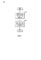
図2は基地局、例えば図1の基地局100と移動局、例えば図1の移動局102との間の信号通信図を示す。典型的に、基地局100と移動局102は、データを互いに往復して送信する。このデータは典型的にデータのパケット内にカプセル化される。カプセル化されたデータはスロット、フレームおよび同類のものとして組織化することができる。データは、これらに限定されないが、音声データ、ウェブデータ、グラフィック、eメール、電子ドキュメント、マルチメディア、および同類のものを含む任意の種類のデータに相当することができる。一実施形態において、ダウンリンクに含まれるデータは移動局102のユーザーのためのデータ並びに移動局102から基地局100に返送されるアップリンク通信のための送信電力制御(TPC)コマンドを含む。
FIG. 2 shows a signal communication diagram between a base station, eg,
TPCは典型的に、受信機、例えば基地局100または移動局102へのアップまたはダウン命令、すなわち送信電力を増加させるか減少させるかを示す1ビットのデータである。典型的には、TPCビットは1デシベル(dB)のインクリメントにおける出力電力または絶対電力による出力電力を制御するように標準化されるが、他の刻み幅を使用するということもあり得る。例えば、一実施形態において、同じ方向(アップ/ダウン)の5つの連続するTPCコマンドが示されるなら、制御された送信機は1dBだけ電力を変化させる。移動局102はTPCを読み、基地局100への通信のためにアップリンクを送信するとき出力電力を増加または減少させる。従って、移動局102は、ダウンリンクのSNRを評価することによりダウンリンクの受信された電力を決定し、移動局は、ダウンリンクの電力のフィードバック制御のためにその独自のTPCコマンドを基地局100に送信する。これは、相対的に一貫したサービス程度(GoS)、例えば顧客により期待される品質、これはフレームエラーレート(FER)により指定することができるが、この品質に対して相対的に一貫して移動局102により受信されるSNRを保持する。
The TPC is typically an up or down command to the receiver, eg, the
同様に、基地局100はまたアップリンクのSNRを評価することによりアップリンクの受信された電力を決定し、基地局100はそれに応じて基地局100における望ましいSNRのためにアップリンクの電力の制御のために移動局102に供給されるTPCを調節する。このアップリンクとダウンリンクを介したTPCコマンドの往復の交換は、有限の期間または無期限に反復されてもよい。
Similarly, the
図3はデータレートの関数として送信された電力を調節することを図解する。データを送信する装置は使用するデータレートを選択する。例えば、携帯電話の呼び出し側が話しをしていると、携帯電話により使用されるデータレートは相対的に高くなる可能性がある。反対に、呼び出し側が沈黙しているとき、携帯電話により使用されるデータレートは相対的に低くなる可能性がある。図3において、時間は水平軸に沿って示される。送信された電力は垂直軸に沿って示される。 FIG. 3 illustrates adjusting the transmitted power as a function of data rate. The device that transmits data selects the data rate to use. For example, if the mobile phone caller is talking, the data rate used by the mobile phone may be relatively high. Conversely, when the caller is silent, the data rate used by the mobile phone can be relatively low. In FIG. 3, time is shown along the horizontal axis. The transmitted power is shown along the vertical axis.
図3に図解されるように、第1の期間302において、データはフルレートでおよび相対的に高い電力レベルで送信される。第2の期間304において、データは1/8のレートおよび相対的に低い電力レベルで送信される。所定のコードレートm/nおよび所定のSNRの場合、1/8レートデータのようなより低いレートデータを送信するために使用される電力は、フルレートデータのようなより高いレートデータよりも低くすることができる。コードレートm/nは畳み込みコードのように、フォワードエラー訂正プロセスに関連して使用されるコードシンボルnの数により分割される非エンコードされたソースシンボルmに相当する。より低いレートデータを送信するために使用される電力は低減することができる。なぜなら、より低いコードレート(より低いm/n)からのさらなるエンコードされたシンボルはより多くのコーディング利得を提供するからである。表Iはデータレート、(畳み込みコードのための)コードレート、および電力オフセット、すなわち、電力のベースラインレベルからの電力の低減の例を図解する。これらの電力オフセットは「β」としても知られている。一実施形態において使用される電力オフセットは、変化するコードレートを有するコーディング利得の相対的な差に相当する。

送信機は送信されているデータのタイプに応答してデータレートを変化させることができる。例えば、デジタルビデオが送信されているとき、相対的にスタティックなフレームは相対的に低いデータレートで送信することができるが、相対的に高いデータレートはより多くのデータを有した相対的にダイナミックなフレームを送信するために必要になるかもしれない。他の例において、携帯電話の呼において呼び出し側のスピーチを運ぶために相対的に高いデータレートが必要になるかもしれない。しかしながら、呼び出し側が沈黙しているとき、相対的に低いデータレートを使用することができる。これらのデータは送信されるデータに応じて変動する可能性がある。しかしながら、送信された電力がデータレートの変化で調節されるなら、既存の受信機は、これらの意図的な電力変化とレイリーフェージングおよび他の環境因子による電力変化を区別することができない。データレートの調節で送信された電力を調節することは望ましく、セルラー通信システムのユーザーの数を増加させることができ、また電池式装置のバッテリ寿命を増加させることができる。 The transmitter can change the data rate in response to the type of data being transmitted. For example, when digital video is being transmitted, relatively static frames can be transmitted at a relatively low data rate, while a relatively high data rate is relatively dynamic with more data. May be needed to send a large frame. In another example, a relatively high data rate may be required to carry the caller's speech in a mobile phone call. However, when the caller is silent, a relatively low data rate can be used. These data may vary depending on the data to be transmitted. However, if the transmitted power is adjusted with changes in data rate, existing receivers cannot distinguish these intentional power changes from those due to Rayleigh fading and other environmental factors. It is desirable to adjust the transmitted power by adjusting the data rate, which can increase the number of users of the cellular communication system and increase the battery life of the battery powered device.
図4はバーストで通信されるデータのグラフィック説明図である。時間は水平軸に沿って示される。送信された電力は垂直軸に沿って示される。左から右に、送信のフルレート部分のためのデータが第1のバーストのデータ402および第2のバーストのデータ404により表される。送信の1/8レート部分のためのデータは第3のバーストのデータ406および第4のバーストのデータ408により表される。例えば、相対的に短いバーストのデータ402は、トラヒックチャネルのためのデータに加えて埋め込まれたデータレート表示410および埋め込まれたTPCビット412を含むことができる。この例において、すなわち、UMTS−TDDの場合データレート表示410はTFCI(トランスポートフォーマットコンビネーションインジケーター)を示すデータレート制御ワードに埋め込まれる。通信リンクは許可されたTFCI値の限定されたセットを有する。これらの値は送信されたデータに使用される特定のタイプのエンコーディングにマップする。例えば、エンコーディングプロセスはいくつかのステップを含んでいてもよい。すなわち、UMTS−TDDの場合、特定の固定のコードレートを有した畳み込みまたはターボエンコーダーを介したチャネルエンコーディングがある。それに続いて、所定の送信に利用可能なシンボルの数に一致させるためにエンコードされたシンボルのパンクチャリングまたは反復を実行する「レートマッチング」ステップがある。それゆえ、TFCI情報は、受信機においてデコーディングプロセスにおいて使用されるチャネルエンコーディングおよび「レートマッチング」パラメーターの特定の組み合わせを識別する。
FIG. 4 is a graphic illustration of data communicated in bursts. Time is shown along the horizontal axis. The transmitted power is shown along the vertical axis. From left to right, data for the full rate portion of the transmission is represented by
図5は目標信号対雑音比(SNR)の適応調整のプロセスを図解する。一実施形態において、少なくとも2つの制御ループが電力制御のために協働する。外部ループは図5に図解される。外部ループは特定のサービス程度(GoS)に対して目標SNRを順応して調節する。フレームデータまたはビットデータエラーレートはGoSの表示として使用することができる。フレームデータエラーレートは、送信されたシンボルをカバーする巡回冗長検査(CRC)情報を用いた場合のようにフォワードエラー制御デコーディング機構を用いて受信機において推定することができる。特定のGoSのための目標SNRは環境条件に応じて変化する可能性がある。例えば、典型的に移動しているユーザーは、同じGoSの場合、静止しているユーザーよりもより良い(より高い)SNR性能を必要とする。 FIG. 5 illustrates the process of adaptive adjustment of the target signal to noise ratio (SNR). In one embodiment, at least two control loops cooperate for power control. The outer loop is illustrated in FIG. The outer loop adapts and adjusts the target SNR for a specific degree of service (GoS). The frame data or bit data error rate can be used as an indication of GoS. The frame data error rate can be estimated at the receiver using a forward error control decoding mechanism, such as when using cyclic redundancy check (CRC) information covering the transmitted symbols. The target SNR for a particular GoS can vary depending on environmental conditions. For example, typically moving users require better (higher) SNR performance than stationary users for the same GoS.
図6乃至図9に関連して後に記載されるであろう内部ループは目標SNRを用いて送信電力制御(TPC)コマンドを発生し、受信したSNRをおおよそ目標SNRに維持する。内部ループは相対的に迅速に実行されるので、移動している移動局102により遭遇されるレイリーフェージングのように、TPCコマンドは相対的に迅速に変化する受信信号強度を補償することができる。一実施形態において、内部ループは外部ループよりより頻繁に実行される。図解されたプロセスはさまざまな方法で変更することができる。例えば、他の実施形態において、図解されたプロセスの種々の部分は結合することができ、代わりのシーケンスで再構成することができ、除去または置き換えすることができ、および同類のことをすることができる。一実施形態において、図5の外部制御ループは汎用プロセッサーまたは特定用途向け集積回路(ASIC)のような専用回路のための命令としてプログラムされたファームウエアにより実施される。しかしながら、外部制御ループはまた専用ハードウエアまたはハードウエアとソフトウエアの組み合わせにより実施することができる。最初に、このプロセスは目標SNRのための所定の値で始めることができる。
The inner loop, which will be described later in connection with FIGS. 6-9, generates a transmit power control (TPC) command using the target SNR and maintains the received SNR approximately at the target SNR. Because the inner loop is executed relatively quickly, the TPC command can compensate for the received signal strength changing relatively quickly, such as Rayleigh fading encountered by the moving
この図解された実施形態において、プロセスは状態510において始まり、送信機から受信されたデータを捕捉する。データは、フレームエラーレートが計算される選択された時間的間隔で捕捉されてもよい。選択された量のデータを捕捉した後に、データはエラーに対して検査され訂正される。例えば、無線ネットワークを介したデジタルデータの送信において、データは畳み込みコードのようなフォワードエラー訂正コードを用いて典型的にエンコードされる。
In this illustrated embodiment, the process begins at
プロセスは状態520に進む。状態520において、フォワードエラー訂正CRCのデコーディングの後で残りのエラーを監視することによりフレームエラーレートが計算される。一実施形態において、フレームエラーレートは時間的間隔において捕捉されたフレームの合計数に対してエラーで発見されたフレームの数を識別することにより決定されてもよい。
The process proceeds to
プロセスは判断ブロック530に進む。ブロック530において、プロセスは、観察されたフレームエラーレートをフレームエラーレートの目標値と比較するために進む。一実施形態において、フレームエラーレートの目標値として1%の目標値が使用される。所望のGoSのための他の適切な値は当業者により容易に決定されるであろう。
The process proceeds to
観察されたフレームエラーレートがフレームエラーレートの目標値より大きいとき、プロセスは判断ブロック530から状態540に進み、目標SNRを増加させる。これは、受信されたSNRを増加させるために内部制御ループにより使用される。内部制御ループは、出力電力の増加が送信装置、例えば、エラー訂正が観察されるデータを送信している基地局100または移動局102から利用可能であるとき、観察されたフレームエラーレートを低減する。
When the observed frame error rate is greater than the frame error rate target value, the process proceeds from
観察されたフレームエラーレートがフレームエラーレートのための目標値より小さければ、プロセスは判断ブロック530から状態550に進み目標SNRを減少する。また、このプロセスは、目標SNRへの調節が行われない中間レンジを提供するように変更することができる。このプロセスは進行中の過程において反復し目標SNRを調節し、選択されたフレームエラーレートを供給する。
If the observed frame error rate is less than the target value for the frame error rate, the process proceeds from
図6は電力制御コマンドを決定するプロセスを図解する。図6に図解されるプロセスは一般的に基地局100または移動局102の電力制御に適用可能である。図解されたプロセスはさまざまな方法で変更することができる。例えば、他の実施形態において、図解されたプロセスの種々の部分は結合することができ、代わりのシーケンスで再構成することができ、除去または置き換えすることができ、同類のことができる。
FIG. 6 illustrates the process of determining power control commands. The process illustrated in FIG. 6 is generally applicable to power control of
このプロセスは「内部」ループに相当する。内部ループにおいて、受信機は送信機と通信し送信機の電力を調節するので、受信機は選択されたSNRを有した送信された信号を受信する。例えば、この相対的に高速な内部ループは、基地局100または移動局102からの出力電力を調節することができる。従って、レイリーフェージングまたは距離による経路損失は、特定のトラヒックチャネルのための送信出力電力における調節を介して適応することができる。送信機の出力電力は実用限界を持つであろう。例えば、出力電力は、増幅器の出力限界により、周波数スペクトルの一部が共有されるユーザーの数により、FCC限界により、基地局サービスエリアにより、および同類のものにより制限することができる。
This process corresponds to an “inner” loop. In the inner loop, the receiver communicates with the transmitter and adjusts the power of the transmitter so that the receiver receives the transmitted signal with the selected SNR. For example, this relatively fast inner loop can adjust the output power from the
図解されたプロセスは状態610において開始する。状態610において、プロセスは変化するデータレートで変化する出力電力を有したトラヒックチャネルの公称SNRを決定する。トラヒックチャネルはさまざまな要因に従ってデータレートにおいて変化することができる。例えば、呼び出し側が話しをしていないとき、ほとんどまたは全くデータは転送されない。しかしながら、呼び出し側が話しをしているとき、相対的により多くのデータが転送され、データレートを増加することができる。上述したように、低いデータレートでデータを運ぶ信号が送信されたとき、低いデータレートのためのコードレートm/nもまた高いデータレート信号のコードレートm/nに対して減少する。(デコーディングの後で)信号のSNRを増加させるより低いコードレートを用いて、受信機において(デコーディングの後で)所定のSNRに対して送信された信号の出力電圧を低下させることができる。ビタビアルゴリズムは畳み込みコードをデコードするために使用することができる技術の一例である。
The illustrated process begins at
送信された出力電力における減少は、(フォワードエラー訂正コードのデコーディングの前に)SNRにおける減少として受信機により感知される。例えば、受信された信号のSNRは、送信機における出力電力における減少に応じて減少する。(関連する送信のコーディング利得を考慮することなく)受信された信号コードチップまたは信号コード化されたシンボルのSNRを用いて送信電力制御を実行する従来の受信機の場合、出力電力における意図的な減少によるSNRのこの減少は、レイリーフェージングのような環境条件による出力電力の変動を識別できないであろう。従って、従来のUMTS TDDシステムは典型的に、送信された信号のデータレートを調節するとき出力電力を調節しない。これは、システムのキャパシティーを不利に完全に利用できず、ほとんどまたは全くデータを受信していないユーザーに、データを受信しているユーザーよりも(デコーディングの後で)相対的により高いSNRを供給する。 The decrease in transmitted output power is perceived by the receiver as a decrease in SNR (before decoding of the forward error correction code). For example, the SNR of the received signal decreases with a decrease in output power at the transmitter. In the case of a conventional receiver that performs transmit power control using the SNR of a received signal code chip or signal-coded symbol (without considering the associated transmission coding gain) This reduction in SNR due to the reduction will not be able to discern variations in output power due to environmental conditions such as Rayleigh fading. Thus, conventional UMTS TDD systems typically do not adjust the output power when adjusting the data rate of the transmitted signal. This disadvantageously takes full advantage of system capacity and gives users who receive little or no data a relatively higher SNR (after decoding) than users who are receiving data. Supply.
意図的に調節された送信された電力に直面して適切なTPCコマンドを発生することができる電力制御技術が必要である。一実施形態はプロセスに相当する。このプロセスは、レイリーフェージングによる経路損失のような経路損失における変動による信号電力の変化と、可変データレートを有した信号を送信するとき、送信機により使用される電力における意図的なオフセットとを区別する。このプロセスは図7に関連して後により詳細に記載されるであろう。これは、TPCに有用な公称または基準電力レベルを有利に発生する。一例において、公称電力レベルがフルレートデータレートのための電力に対して参照されるがもちろん任意の基準レベルを使用することができる。 There is a need for a power control technique that can generate appropriate TPC commands in the face of intentionally adjusted transmitted power. One embodiment corresponds to a process. This process distinguishes between changes in signal power due to variations in path loss, such as path loss due to Rayleigh fading, and intentional offsets in the power used by the transmitter when transmitting signals with variable data rates. To do. This process will be described in more detail later in connection with FIG. This advantageously generates a nominal or reference power level useful for TPC. In one example, the nominal power level is referenced to the power for the full rate data rate, but of course any reference level can be used.
一実施形態は、対応するトラヒック信号のSNRのためのプロキシとしてビーコン信号またはパイロット信号のSNRのような、(電力制御されていない)固定の電力レベルで送信された他の信号のSNRを使用する。この技術は、基地局100のように、そのようなビーコン信号またはパイロット信号を放射するステーションの送信電力制御(TPC)に対してのみ適用可能である。ビーコン信号またはパイロット信号は、電力制御されるビーコン信号またはパイロット信号とトラヒック信号との間でレイリーフェージングが類似するトラヒックチャネルに時間および周波数において相対的に近接していなければならない。また、ビーコン信号またはパイロット信号はトラヒックチャネルと同じ送信ソースから放射されなければならない。
One embodiment uses the SNR of other signals transmitted at a fixed power level (not power controlled), such as the SNR of a beacon signal or pilot signal, as a proxy for the SNR of the corresponding traffic signal . This technique is applicable only to transmission power control (TPC) of a station that emits such a beacon signal or pilot signal, such as the
プロセスは判断ブロック620に進む。判断ブロック620において、公称SNRは目標SNRと比較される。例えば、SNRのための目標値は、図5に関連して上述したように順応して決定することができる。SNRのための目標値は時間に対して順応して変化することができるけれども、それは、典型的に、図6の電力制御プロセスの実行速度に比べて相対的にゆっくりと変化する。電力制御ループの内部ループを理解する目的のために、SNRのための目標値は固定であると考えることができる。公称SNRは対応するデータを運んでいるトラヒックチャネルのSNRであり得るし、またはプロキシとして使用されているビーコン信号またはパイロット信号のような他の信号のSNRであり得る。
The process proceeds to
公称SNRが目標SNR未満であるとき、プロセスは判断ブロック620から状態630に進み、電力を増加する要求は受信機により発生され送信機に送信される。従って、将来の送信は、(送信機の電力限界内で)公称SNRを引き上げるために増加された電力の送信になるであろう。一実施形態において、ステーションはバイナリ送信電力制御(TPC)ビットを用いてこの情報を通信する。TPCビットは、相対的な増加により対応するトラヒックチャネルのための出力電力を調節(上昇または下降)するように送信機に示す。例えば、一実施形態において、この増加は1dBに相当するが、他のステップサイズを使用することができる。
When the nominal SNR is less than the target SNR, the process proceeds from
公称SNRが目標SNRより大きいとき、プロセスは判断ブロック620から状態640に進み、電力の減少の要求が発生される。例えば、この要求は下降調節に相当するTPCビットに相当することができる。
When the nominal SNR is greater than the target SNR, the process proceeds from
オプションの状態650を有する一実施形態において、プロセスは状態630または状態640からオプションの状態650に進み、プロセスは電力調節要求を監視し、送信機により使用されるTPC調節の量を推定する。監視はオプションであり、決定されたデータレートを用いて公称SNRを決定するためのプロセスとともに使用されない。これは、図7に関連して記載されるであろう。しかしながら、監視は、図8に関連して記載されるであろう他の信号を用いて公称SNRを決定するためのプロセスとともに使用されるとき有用であり得る。単一ビットTPCコマンドが上昇および下降調節のために使用される場合、およびステップサイズが1dBのような一定の値に相当する場合、電力調節のためのログ管理は上昇調節のための合計と下降調節のための合計に相当することができる。
In one embodiment with
図7はデータレートに基づいて公称または基準信号対雑音比(SNR)を決定するプロセスを図解する。図解されたプロセスは基地局100と移動局102の両方に適用可能である。このプロセスは図6に図解されたプロセスの状態610に対して使用することができる。このプロセスはレイリーフェージングのような環境ソースによる受信された信号電力における変化からデータレートの変化に対して実行される電力調節を区別する。図解されたプロセスはさまざまな方法で変更することができる。例えば、他の実施形態において、図解されたプロセスの種々の部分は結合することができ、代わりのシーケンスで再構成することができ、除去または置き換えすることができ、および同類のことをすることができる。
FIG. 7 illustrates a process for determining a nominal or reference signal-to-noise ratio (SNR) based on the data rate. The illustrated process is applicable to both
図解されたプロセスは、受信されたデータ信号のSNRを決定することにより第1の状態710において開始する。この特定のSNRは送信に関連するコーディング利得を補償する前にSNRに相当する受信されたデータ信号のための信号コードチップまたはシンボルのSNRに相当し、それゆえ変化するデータレートで受信されたデータ信号を送信するとき行われる電力の調節に従って変化する。信号コードチップのためのまたはデコーディング前のSNRの測定はCDMA受信機により実行されてもよい、特にTPCを用いたCDMA受信機により実行されてもよいプロセスである。例えば、3GPPP技術標準ドキュメントの25.214物理層手続(FDD)を参照されたい。特に、TPCの議論、受信された信号コード電力(RSCP)、干渉信号コード電力(ISCP)、信号対干渉比(SIR)および同類のものを参照されたい。
The illustrated process begins in a
プロセスは状態720に進む。状態720において、プロセスは、受信されたデータレートを決定するために進む。データレートは制御ワードから検索することができ、受信されたSNRから推測することができる等である。UMTS−TDDシステムにおいて、受信されたデータレートは、埋め込まれた制御ワードであるデータレート制御ワードから検索することができる。図9に関連してさらに詳細に記載されるであろう一実施形態において、送信データレートを用いて受信されたデータレートの推定値を発生する。
The process proceeds to
プロセスは状態730に進む。状態730において、プロセスは、受信された信号を受信機に送信する際に送信機により使用される電力オフセットまたは電力の調節に関連づけるために手続をする。この関連する電力オフセットまたは調節は受信された信号のデータレートに釣り合っている。非常に広い範囲の技術を用いて電力オフセットをデータレートに関連させることができる。例えば、対称なシステムにおいて、基地局100と移動局102が信号のためのデータを送信するために使用されるデータレートを選択することができ、選択されたデータレートに従って送信された出力信号電力レベルを調節することができるなら、フルデータレートのために使用される電力からの電力(電力オフセット)におけるルックアップテーブル参照低減は典型的に送信機上で使用される電力を計算するために存在する。そのような表の一例は表1において上述した。対称システムにおいて、基地局100と移動局102は実質的に同じ方法でデータレートの変化に対して電力を調節しなければならない。従って、送信側のために使用されるルックアップテーブルは受信側において再使用することができ、適用される電力オフセットを決定することができる。
The process proceeds to
他の変形例を適用することができる。例えば、電力オフセットは、フルデータレートより低いデータレートの使用によるコーディング利得の計算から推定することができる。 Other variations can be applied. For example, the power offset can be estimated from a coding gain calculation by using a data rate lower than the full data rate.
一実施形態において、電力オフセットはデータレートの範囲に関係する。これは、例えば、データレートが計算され、例えば、送信されたデータのバースト性、短いサンプリング期間および同類のものにより実際のデータレートが確信して知られていないとき、有用であり得る。 In one embodiment, the power offset is related to the range of data rates. This can be useful, for example, when the data rate is calculated and the actual data rate is not known with certainty, for example due to the burstiness of the transmitted data, short sampling periods and the like.
多くの通信システムにおいて、通信はデュプレックスであり得る。UMTS−TDDシステムにおいて、基地局と移動局からの通信は、同じ周波数チャネルを用いた時分割デュプレックスであり得る。一実施形態において、ステーション外に送信されるトラヒック信号の送信されたデータレートは電力オフセットの選択をバイアスするために使用される。これは、図9に関連して後でより詳細に述べられるであろう。 In many communication systems, the communication can be duplex. In the UMTS-TDD system, the communication from the base station and the mobile station can be time division duplex using the same frequency channel. In one embodiment, the transmitted data rate of traffic signals transmitted outside the station is used to bias the selection of power offset. This will be described in more detail later in connection with FIG.
プロセスは状態740に進む。状態740において、プロセスは受信された信号の受信されたSNRおよび受信された信号のデータレートに関連する電力オフセットから公称SNRを計算するための手続をする。例えば、方程式1は公称SNRのための計算の一例を例証する。
方程式1において、信号対雑音比および電力オフセットはデシベルで表される。方程式1において変数RxSNR(nom)は変化するデータレートによる意図的な電力調節のために望ましく補償される公称SNRに相当する。変数RxSNR(obs)は、状態710において決定された受信されたデータ信号の観察されたSNRに相当する。変数PowerOffset(dB)は関連する電力オフセットに相当する。変数PowerOffset(dB)は、送信された電力がフルレート未満に対して下降に調節されるとき(デコーディングの前に)生じるSNRの減少を補償する。
In
図8はトラヒックチャネルの信号対雑音比(SNR)のための基準としてビーコン信号またはパイロット信号のような他の信号を用いたプロセスを図解する。この開示のために、「ビーコン」という用語は、基地局100に同期するために、システム情報を運ぶために、基地局へのまたは基地局からのハンドオーバープロセスを支援するためおよび同類のもののために、複数の加入者、例えば複数の移動局102により受信されることが意図される基地局100からの信号のような相対的に一定の電力で提供される基地局100からの任意の信号を記載するために使用されるであろう。典型的に一定であるけれども、基地局100からのビーコン信号の電力は、基地局100中の加入者の負荷バランシングのために相対的にゆっくりと変化することができる。ビーコン信号は典型的に他の目的のために使用されるので、ビーコンSNRの測定は典型的にすでに実行され利用可能である。
FIG. 8 illustrates a process using other signals such as beacon signals or pilot signals as a reference for the signal-to-noise ratio (SNR) of the traffic channel. For the purposes of this disclosure, the term “beacon” is intended to synchronize with the
図解されたプロセスにおいて、ビーコン信号のSNRはトラヒックチャネルのSNRのためのプロキシとして使用される。レイリーフェージング特性が類似していることを保証するために、ビーコン信号はトラヒックチャネルとほぼ同じ時間と周波数の信号であることが望ましい。さらに、図8に描かれたプロセスに適用可能な相対的に一定の出力電力を有したビーコン信号を有することが望ましい。また、携帯電話ネットワークとの関連で、ビーコン信号は典型的には、単に基地局100により発生され、移動局102により典型的に発生されない信号である。図解されたプロセスはさまざまな方法で変更することができる。例えば、他の実施形態において、図解されたプロセスの種々の部分は、結合することができ、代わりのシーケンスにおいて再構成することができ、除去または置き換えることができ、および同類のことができる。
In the illustrated process, the SNR of the beacon signal is used as a proxy for the SNR of the traffic channel. In order to ensure that the Rayleigh fading characteristics are similar, it is desirable that the beacon signal is a signal of approximately the same time and frequency as the traffic channel. In addition, it is desirable to have a beacon signal with a relatively constant output power applicable to the process depicted in FIG. Also, in the context of a cellular network, a beacon signal is typically a signal that is simply generated by the
図解されたプロセスは送信電力制御(TPC)の下で基地局100からビーコン信号のSNRを決定することにより第1の状態810で始まる。複数の基地局102は重複したエリアを持つことができるので、移動局102は一度に2以上のビーコン信号を受信することができる。しかしながら、電力制御のために、関心のある1つ以上のビーコン信号は、またTPCの下で移動局102にダウンリンクを送信している特定の基地局100からのビーコン信号に相当する。この実施形態において、ビーコン信号の電力は相対的に一定であるので、受信されたビーコン信号のSNRの変化は、経路損失によることができる。さらに、ビーコン信号とトラヒックチャネルの時間と周波数は相対的に近接しているかまたは同じであるとき、ビーコン信号により経験される環境条件はまたトラヒックチャネルにより経験されなければならない。
The illustrated process begins in a
プロセスはオプションの状態820に進む。この状態において、プロセスは、ビーコンと、前記トラヒックチャネルに関する公称電力および/またはSNRとの間の電力および/またはSNRオフセットを決定する。ビーコン信号は、トラヒックチャネルのための信号よりも高い出力電力レベルのような異なる電力レベルで提供することができる。これらの電力レベルは要望通り変換または翻訳することができる。しかしながら、ビーコン電力レベルとSNRレベルをトラヒックチャネルレベルに変換するよりもむしろ、図6に関連して上述したプロセスは、ビーコン信号SNRに基づきおよび従前のTPCコマンドに対して調節される目標SNRを使用することができる。それによりそのような変換動作を取り除く。
The process proceeds to an
プロセスは状態830に進む。状態830において、プロセスは、送信機により現在使用中の既存のTPCオフセット電力を決定する。ビーコン信号の電力は相対的に一定であるが、トラヒックチャネルの電力はTPCに従って変化する。一実施形態において、プロセスはトラヒックチャネルに対して行われたTPC調節を追跡し、ビーコン信号SNRをトラヒックチャネルに対して行われた電力調節に正規化する。一例において、TPCコマンドが上昇コマンドまたは下降コマンドのための単一ビットのデータに相当する場合、プロセスは、上昇コマンドおよび下降コマンドの連続した合計を維持することができる。これらの上昇コマンドおよび下降コマンドは結合されて以前に受信されたTPCコマンドによる基地局102により使用される電力オフセットの推定値を発生することができる。
The process proceeds to
例えば、100の下降コマンドが80の上昇コマンドと合計されるなら、プロセスは、20の下降コマンドの正味の数量に相当するTPC電力オフセットで基地局102がトラヒックチャネルを動作していることを決定することができる。例えば、各TPCコマンドが1デシベル(dB)に相当する場合、これは、20dBの電力の相対的低減の推定値を生じるであろう。
For example, if 100 down commands are summed with 80 up commands, the process determines that the
移動局102と基地局100との間の通信はしばしば不完全である。
Communication between the
時々、データは落とされる。従って、移動局がTPC制御に対して送信したと決定したものと、基地局100が正しく受信したものとの間にずれがある可能性がある。これは、少なくとも不定期のベースで基地局102から移動局100に絶対基準を通信することにより改善することができる。従って、基地局100は、基地局100で使用される実際の量のオフセットで更新することができる。
Sometimes data is dropped. Therefore, there is a possibility that there is a difference between what the mobile station has determined to transmit for TPC control and what the
プロセスは状態840に進む。状態840において、プロセスは、ビーコン信号のSNRと、TPCコマンドからの電力オフセットを用いて受信された信号の公称SNRのための推定値を計算する。電力差および/またはビーコン信号とトラヒックチャネルとの間のコーディングのためにさらなるオフセットが存在する可能性があるが、これらの差は、目標SNRまたは同種のものに対して補償値を選択することを介して、相対的にスタティックな変数または定数を用いることにより容易に適合することができる。
The process proceeds to
方程式2および3は公称SNRを発生するために使用することができる方程式の例を表す。方程式2において、SNRはビーコン信号SNRに関して維持される。方程式3において、SNRはトラヒック信号SNRに変換または翻訳される。
方程式2において、BSNR(ref)は、基準SNRに相当し、BSNR(obs)は、観察されたビーコン信号SNRに相当し、TP(offset)は、累積されたTPCコマンドからの推定されたオフセット電力に相当する。さらに、方程式3において、RxSNR(REF)は、基準SNRに相当し、BP(offset)は、(TPC調節を考慮しない)出力電力の変化によるビーコン信号SNRとトラヒックチャネルSNRと、コーディング利得のような因子によるSNR差との間のオフセットに言及する。 In Equation 2, BSNR (ref) corresponds to the reference SNR, BSNR (obs) corresponds to the observed beacon signal SNR, and TP (offset) is the estimated offset power from the accumulated TPC command. It corresponds to. Furthermore, in Equation 3, RxSNR (REF) corresponds to the reference SNR, and BP (offset) is a beacon signal SNR and traffic channel SNR due to changes in output power (not considering TPC adjustment), such as coding gain. Refers to the offset between the SNR differences due to factors.
図9は受信されたデータレートを推定する方法の一例を図解する。例えば、この方法は、この方法が知られていないとき、データレートを推定するための他の技術と組み合わせてデータレートを推定するために、また、測定されたものまたは推定されたものであろうとなかろうと、既存のデータレート推定値をバイアスするために使用することができる。 FIG. 9 illustrates an example of a method for estimating the received data rate. For example, the method may be measured or estimated to estimate the data rate in combination with other techniques for estimating the data rate when the method is not known. Nevertheless, it can be used to bias existing data rate estimates.
図解されるプロセスは、送信されているデータのデータレートを検索することにより状態910において始まる。ステーションは送信されたデータレートに対して制御を有するが、(少なくとも電力制御に対してタイムリーな方法で)受信されているデータのデータレートを知っている必要は必ずしもない。プロセスは状態920に進み、状態920において、送信されたデータは、受信されたデータレートを推定するために使用される。多くのインスタンスにおいて、送信されたデータレートと受信されたデータレートは関連している。
The illustrated process begins at
以下は、どのように技術を使用することができるかの一例である。可変レートデータのためのデータのソースの共通の例は音声通信である。呼び出し側は、話し、沈黙し、再び話しし、再び沈黙する等である。多くのインスタンスにおいて、2人の人が話しをしているとき、一方は聞いており、他方は話をしている、逆の場合も同じである。従って、ステーション(移動局または基地局)が音声呼を処理しているときでかつ送信されているデータのためのデータレートが相対的に高いとき、入力データレートは相対的に低いと予想することができる。反対に、送信されているデータレートが相対的に低いと、入力データレートは相対的に高いと予想することができる。 The following is an example of how the technology can be used. A common example of a data source for variable rate data is voice communication. The caller speaks, silences, speaks again, silences again, and so on. In many instances, when two people are talking, one is listening and the other is talking, and vice versa. Therefore, when a station (mobile station or base station) is processing a voice call and the data rate for the data being transmitted is relatively high, the input data rate is expected to be relatively low Can do. Conversely, if the data rate being transmitted is relatively low, the input data rate can be expected to be relatively high.
例えば、送信されたデータは変換され、受信されたデータレートの推定値を発生することができ、図7の状態720において使用することができる。他の例において、送信されたデータレートは、他の方法により決定される受信されたデータレートをバイアスするために使用することができる。例えば、データレート対電力オフセットの一次元のルックアップテーブルは、送信されたデータレートに対応する余次元を備えた2次元テーブルに変換することができる。他の方法において、送信されたデータレートを用いてデータレートまたは電力オフセットを変更するために数式を使用することができる。
For example, the transmitted data can be converted to generate an estimate of the received data rate and can be used in
図10は、電力制御コマンドを発生するために使用することができるプロセッサー1000の一例を図解する。プロセッサー1000の種々のモジュールは、ハードウエアで、ソフトウエア(ファームウエア)で、またはハードウエアとソフトウエアの両方の組み合わせで実施することができる。種々のモジュールは再構成することができ、結合することができ、削除することができる等である。例えば、図解された例は、パラメーターの計算を示していてもよいが、他の実施形態では、パラメーターは検索されてもよいし他のデータから推測されてもよい。
FIG. 10 illustrates an example of a
図10に示すように、プロセッサー1000は、フレームエラーレート(F.E.R.)計算モジュール1002、目標SNR計算モジュール1004、信号対雑音比(SNR)計算モジュール1006、公称SNR計算モジュール1008、および送信電力制御(TPC)コマンド発生器1010により表される。フレームエラーレート(F.E.R.)計算モジュール1002は、受信されたデータのための実際のF.E.R.を計算する。実際のF.E.R.および目標F.E.R.は、目標SNR通信モジュールに対する入力として供給される。目標SNR計算モジュールは目標SNRを発生する。
As shown in FIG. 10, the
信号対雑音比(SNR)計算モジュール1006はSNRのような信号特性を計算する。SNRと電力オフセットは、公称SNR計算モジュール1008への入力として供給される。1つの例において、電力オフセットはデータレートを用いて決定される。公称SNR計算モジュール1008は出力として公称SNRを発生する。
A signal to noise ratio (SNR)
目標SNRおよび公称SNRは送信電力制御(TPC)コマンド発生器1010への入力として供給される。TPCコマンド発生器1010はTPCコマンドを発生する。例えば、これらのコマンドは送信された電力の増加または減少を要求するために使用することができる。
The target SNR and nominal SNR are provided as inputs to a transmit power control (TPC)
UMTS TDDシステムとの関連において電力制御のさらなる詳細は、低チップレート(LCR)および高チップレート(HCR)システムに対する以下の説明においてさらに詳細に記載されるであろう。 Further details of power control in the context of a UMTS TDD system will be described in further detail in the following description for low chip rate (LCR) and high chip rate (HCR) systems.
低チップレート(LCR)システムにおける電力制御
LCRのスロット構造は、電力制御ビットをミッドアムブル(midamble)の後に置く。同じスロット構造はDL TPCビットを運ぶアップリンク(UL)スロットおよびUL TPCビットを運ぶダウンリンク(DL)スロットに適用される。
Power Control in Low Chip Rate (LCR) Systems The LCR slot structure places the power control bits after the midamble. The same slot structure applies to uplink (UL) slots carrying DL TPC bits and downlink (DL) slots carrying UL TPC bits.
同期シフト(SS)ビットのためのフィールド長はTPC ビットのフィールド長と同じである。TFCI(トランスポートフォーマットコンビネーションインジケーター)フィールドは、スロットフォーマットに応じて存在してもよいし存在しなくてもよい。TFCIコードワードは無線フレーム(10ms)に及びそれゆえ2つの5msサブフレームに及ぶことに留意する必要がある。 The field length for the sync shift (SS) bit is the same as the field length of the TPC bit. The TFCI (Transport Format Combination Indicator) field may or may not exist depending on the slot format. It should be noted that the TFCI codeword spans a radio frame (10 ms) and hence two 5 ms subframes.
DLスロットにおいて、異なるユーザーからのTPCビットはSF 16コードを用いた符合分割多重化である。ULスロットにおいて、TCPビットはデータ部分に使用される拡散因子と同じ拡散因子を使用する。各ユーザーのためのTPCビットは、(レートマッチングから)最も低い物理チャネルシーケンス番号に対応する物理チャネルにおいて送信される。LCRは(より高次の層により構成される)所定のユーザーのためのTPCビットの送信のために2つ以上のコードを用いることを可能にする。 In the DL slot, TPC bits from different users are code division multiplexed using SF 16 code. In the UL slot, the TCP bits use the same spreading factor as that used for the data portion. The TPC bits for each user are transmitted on the physical channel corresponding to the lowest physical channel sequence number (from rate matching). LCR allows more than one code to be used for transmission of TPC bits for a given user (configured by higher layers).
例えば、TPCフィールドとSSフィールドは以下の長さを持つことができる。 For example, the TPC field and the SS field can have the following lengths:
(i)SFチップ/スロットに対応する1TPC変調シンボル/スロット、QPSKの場合、1変調シンボルは、2ビットに相当し、8PSKの場合、1変調シンボルは3ビットに相当する。 (I) In the case of 1TPC modulation symbol / slot corresponding to SF chip / slot, QPSK, 1 modulation symbol corresponds to 2 bits, and in the case of 8PSK, 1 modulation symbol corresponds to 3 bits.
(ii)TPC変調シンボル/スロットはない。16チップ/スロットに対応する16/SF変調シンボル/スロット。この場合SFは16以下であり、QPSKの場合16/SF変調シンボルは、2*16/SFビットに相当し、8PSKの場合、16/SF変調シンボルは3*16/SFビットに相当する。 (Ii) There are no TPC modulation symbols / slots. 16 / SF modulation symbols / slots corresponding to 16 chips / slots. In this case, SF is 16 or less. In the case of QPSK, the 16 / SF modulation symbol corresponds to 2 * 16 / SF bits, and in the case of 8PSK, the 16 / SF modulation symbol corresponds to 3 * 16 / SF bits.
HCRにおける電力制御
HCRのスロット構造は電力制御ビットをミッドアンブル(midamble)の後に置く。HCR内のL1制御シグナリングに基づいたUL電力制御がないので、HCR内のDLスロットはTPCビットを運ばない。代わりにより遅い電力制御メッセージがサポートされる。TFCIフィールドは、スロットフォーマットに応じてスロット中に存在していてもよいし、存在していなくてもよい。LCRの場合におけるように、TFCIコードワードは無線フレーム(10ms)に及ぶ。
Power Control in HCR The HCR slot structure places the power control bits after the midamble. Since there is no UL power control based on L1 control signaling in HCR, DL slots in HCR do not carry TPC bits. Instead, slower power control messages are supported. The TFCI field may or may not exist in the slot depending on the slot format. As in the case of LCR, the TFCI codeword spans a radio frame (10 ms).
ULスロットにおいて、許可されたOVSFサブツリーの最も高い番号づけを有するブランチ内のチャネル化コードを用いてSF 16でTPCビットが送信される。例えば、TPCフィールドは以下の長さを持つことができる。 In the UL slot, the TPC bit is transmitted at SF 16 using the channelization code in the branch with the highest numbering of allowed OVSF subtrees. For example, the TPC field can have the following length:
(i)16チップ/スロットに対応するTPC変調シンボル(QPSK変調を用いた場合、1TPC変調シンボル/スロットは2 TPC ビット/スロットに相当する)
(ii)TPC変調シンボル/スロットはない。
(I) TPC modulation symbol corresponding to 16 chips / slot (when QPSK modulation is used, 1 TPC modulation symbol / slot corresponds to 2 TPC bits / slot)
(Ii) There are no TPC modulation symbols / slots.
(iii)HS−SICHのみに対して許可された64チップ/スロットに相当する4TPC変調シンボル/スロット(QPSK変調を用いた場合、4TPC変調シンボル/スロットは8TPCビット/スロットに相当する)。 (Iii) 4TPC modulation symbols / slots corresponding to 64 chips / slots allowed for HS-SICH only (when using QPSK modulation, 4TPC modulation symbols / slots correspond to 8 TPC bits / slots).
「物理チャネルおよび物理チャネル(TDD)へのトランスポートチャネルのマッピング」(Physical Channels and mapping of transport channels onto physical channels (TDD))というタイトルの3GPP技術規格(TS)25.221は、タイムスロット内の送信電力はUMTS TDDシステムの場合一定であると明記している。TPCビットの送信に対して任意の電力オフセットを許容する明確な言及はない。それゆえ、TPC変調シンボルはデータ変調シンボルの電力レベルと同じ電力レベルで送信される。DLにおいて、異なるユーザーのためのTPCビットの送信は同時に生じる。現在のスロット構造に従うTPCビットの電力オフセット(ブースト)は、典型的に短期間、送信電力の増加を生じさせるであろう(これは、非線形領域における電力増幅器の動作により送信された波形の歪みを生じる可能性がある)。 The 3GPP Technical Standard (TS) 25.221 titled “Physical Channels and mapping of transport channels onto physical channels (TDD)” It is specified that the transmission power is constant for the UMTS TDD system. There is no explicit mention to allow any power offset for the transmission of TPC bits. Therefore, the TPC modulation symbol is transmitted at the same power level as the data modulation symbol. In DL, transmission of TPC bits for different users occurs simultaneously. A power offset (boost) of the TPC bits according to the current slot structure will typically cause an increase in transmit power for a short period of time (this reduces the distortion of the transmitted waveform due to the operation of the power amplifier in the nonlinear region). May occur).
CDMAシステムはより低いデータレートに対して送信電力を低減することにより音声活動を利用することを可能にする。音声活動を利用することができるために、電力制御コマンドは公称基準に対して導き出されなければならない。次に、特定のチャネルの送信電力は最後の電力制御コマンドと、送信されているレートと公称基準との間の電力オフセットで訂正されるであろう。公称基準を介して電力制御を実行する多くの方法がある。例えば、電力制御チャネルは周知の基準電力で送信することができる。このチャネルのSNRは受信機において計算され、上昇/下降コマンドはしきい値との比較(電力制御セットポイント)により発生される。次に、送信機はこのコマンドを用いて送信電力を訂正することができ、送信されたデータレート(TFC)に応じて送信電力をさらに弱めるであろう。 A CDMA system allows voice activity to be utilized by reducing transmit power for lower data rates. In order to be able to take advantage of voice activity, power control commands must be derived against nominal criteria. The transmit power for a particular channel will then be corrected with the last power control command and the power offset between the rate being transmitted and the nominal reference. There are many ways to perform power control via a nominal reference. For example, the power control channel can be transmitted with a known reference power. The SNR of this channel is calculated at the receiver, and up / down commands are generated by comparison with a threshold (power control setpoint). The transmitter can then use this command to correct the transmit power and will further weaken the transmit power depending on the transmitted data rate (TFC).
WCDMA(登録商標)システムとCDMA2000システムは、特定のEc/Iorでパイロットチャネルを送信する。それゆえ、上昇/下降TPCコマンドの発生のためにパイロットチャネルのSNRを使用することができる。UMTS TDDシステムにおけるミッドアンブル(midamble)は、WCDMAシステムおよびcdma2000システムと同等のものを構成する。しかしながら、残念なことに、それらは固定された電力で送信されず、それゆえ電力制御のための公称基準として使用することはできない。 The WCDMA (registered trademark) system and the CDMA2000 system transmit a pilot channel with a specific Ec / Ior. Therefore, the SNR of the pilot channel can be used for the generation of up / down TPC commands. The midamble in the UMTS TDD system constitutes the equivalent of the WCDMA system and the cdma2000 system. Unfortunately, however, they are not transmitted with a fixed power and therefore cannot be used as a nominal reference for power control.
UMTS TDDシステムはビーコンチャネルを使用する。ビーコンチャネルは基準電力で周知のスロットで送信される。ビーコンチャネルのSNRは可変レート電力制御のために使用される公称基準として使用することができる。TPCビットの受信における信頼性と可変レート接続の電力制御は、UMTS−TDDシステムおよび他のシステムに対して特徴であり得る。これらの2つの問題は以下にさらに詳細に記載されるであろう。 The UMTS TDD system uses a beacon channel. The beacon channel is transmitted in a known slot with reference power. The SNR of the beacon channel can be used as a nominal reference used for variable rate power control. Reliability in receiving TPC bits and power control of variable rate connections may be a feature for UMTS-TDD systems and other systems. These two issues will be described in more detail below.
TPCビットの受信における信頼性
TPC変調シンボルはデータ変調シンボルと同じ電力レベルで送信される。可変レート接続において、音声活動が利用されるなら、より低いコードレートで保護されるより低いデータレートはより低い電力で送信することができ、より高いデータレートはより高い電力で送信することができる。従って、異なるデータレートの場合にTPCビットに対して同じコーディングが使用されるなら、より低いデータレートでフレームで送信されたTPCビットは、より高いデータレートでフレームで送信されたものよりも信頼性が低い。これはまたスロット内に埋め込まれて送信される他のレイヤー1制御情報に適用される。この他のレイヤー1制御情報はTFCIを含み、LCRの場合には、SSビットも含む。このシナリオは、最悪の場合(最も低い送信電力)は十分な復調信頼性を提供しなければならない方法で対処しなければならない。
Reliability in reception of TPC bits TPC modulation symbols are transmitted at the same power level as data modulation symbols. In a variable rate connection, if voice activity is utilized, a lower data rate protected with a lower code rate can be transmitted at a lower power and a higher data rate can be transmitted at a higher power . Thus, if the same coding is used for TPC bits for different data rates, TPC bits transmitted in frames at lower data rates are more reliable than those transmitted in frames at higher data rates. Is low. This also applies to
可変レート接続の電力制御
異なるデータレートは異なるコードレートを有する。それゆえ、所定のGoS受信、例えばFER約1%、に使用される送信電力は異なるデータレートに対して異なる。可変レート接続において、音声活動が利用されるなら、受信機は電力を適切なセットポイントに制御する必要がある。公称セットポイントは選択することができる。例えば、最も高いコードレートを有したTFCを選択することができる。それゆえ、最も高い電力要件および最も高い電力制御ビットはその公称基準に対して導き出すことができる。公称基準に対して異なるTFCのための電力オフセットが送信機において周知なら、公称基準に対して導き出された電力は任意の他のTFCのための送信電力を設定するために使用することができる。
Power control for variable rate connections Different data rates have different code rates. Therefore, the transmit power used for a given GoS reception, eg, about 1% FER, is different for different data rates. In a variable rate connection, if voice activity is utilized, the receiver needs to control the power to an appropriate setpoint. A nominal setpoint can be selected. For example, the TFC with the highest code rate can be selected. Therefore, the highest power requirement and the highest power control bit can be derived against its nominal reference. If the power offset for a different TFC relative to the nominal reference is known at the transmitter, the power derived relative to the nominal reference can be used to set the transmit power for any other TFC.
レート決定ベースの可変レート電力制御
一実施形態は、各無線フレームの終わりにおけるレート決定に基づいている。レートが知られている場合、受信されたSNRを比較するために必要とされるSNRしきい値(電力制御セットポイント)は知られている。それゆえ、適切な電力制御コマンドを発生することができる。「多重化およびチャネルコーディング(TDD)」(Multiplexing and channel coding (TDD))というタイトルの3GPP技術基準(TS)25.222はUMTS TDDシステムのためのTFCIコーディングを指定する。
Rate Determination Based Variable Rate Power Control One embodiment is based on rate determination at the end of each radio frame. If the rate is known, the SNR threshold (power control setpoint) needed to compare the received SNR is known. Therefore, an appropriate power control command can be generated. The 3GPP Technical Standard (TS) 25.222 entitled “Multiplexing and channel coding (TDD)” specifies TFCI coding for the UMTS TDD system.
TFCIフィールドのコーディングはLCR(QPSK)およびHCRの場合と同じである。符号化すべきTFCIビットの数に応じて3つのタイプのコーディングがある。 The coding of the TFCI field is the same as in LCR (QPSK) and HCR. There are three types of coding depending on the number of TFCI bits to be encoded.
(i)TFCIフィールド長6−10ビット:(32,10)二次RMコード、長さが10ビット未満ならゼロパディングが10ビット(MSB乃至0)に使用され、およびNTFCI_codeword:32のコード化されたシンボル
(ii)TFCIフィールド長3−5ビット:(16,5)バイオーソゴナルコード(bi-orthogonal)、長さが5ビット未満なら、5ビット(MSB乃至0)に対してゼロパディングが使用される。およびNTFCI_codeword:16のコード化されたシンボル
(iii)TFCIフィールド長1−2ビット:(4,1)または(8,2)反復コード、及びNTFCI_codeword:4または8のコード化されたシンボル
任意の構成要素における最小のTTIが20ms以上なら、TTI内の連続するフレーム内のコードワードの反復が使用される。
(I) TFCI field length 6-10 bits: (32,10) secondary RM code, zero padding is used for 10 bits (MSB to 0) if length is less than 10 bits, and NTFCI_codeword: 32 coded Symbol (ii) TFCI field length 3-5 bits: (16,5) Bio-Sogonal Code (bi-orthogonal), if length is less than 5 bits, zero padding for 5 bits (MSB to 0) used. And NTFCI_codeword: 16 coded symbols (iii) TFCI field length 1-2 bits: (4,1) or (8,2) repetitive code, and NTFCI_codeword: 4 or 8 coded symbols Arbitrary configuration If the minimum TTI in the element is 20 ms or more, the repetition of codewords in consecutive frames within the TTI is used.
音声接続において、構成要素TrCHは、20ms以上のTTIを有し(DTCH TTI=20ms、DCCH TTI=40ms)、同じTFCIコードワードが20msTTIの2つの無線フレームで送信される。受信データレートは20msTTIの2つの無線フレームの各々の後で推定することができる。 In a voice connection, the component TrCH has a TTI of 20 ms or more (DTCH TTI = 20 ms, DCCH TTI = 40 ms), and the same TFCI codeword is transmitted in two radio frames of 20 ms TTI. The received data rate can be estimated after each of the two radio frames of 20 ms TTI.
これはHCRのための効率的な可変レート電力制御を可能にする(音声接続の場合、10msの無線フレーム毎に1つの使用されたスロットがある。図3参照)が、LCRの場合適切ではないであろう(音声接続の場合、5msのサブフレーム毎に1つの使用されたスロットがある)。一実施形態において、LCRの場合、現在の仕様の変更を実施することができる。現在の仕様の変更はTFCIコードワードを変化させて10ms無線フレームに広げるのとは対照的に5msサブフレームに広げる。 This enables efficient variable rate power control for HCR (for voice connections there is one used slot for every 10 ms radio frame, see Figure 3), but not appropriate for LCR (For voice connections, there will be one used slot every 5 ms subframe). In one embodiment, for LCR, changes to the current specification can be implemented. The current specification change extends to 5 ms subframes as opposed to changing the TFCI codeword to 10 ms radio frames.
HCRにおいて、10ms間隔ごとに1つのTPCビットがあり、電力制御レートは約100Hzである。他方、LCRにおいて、5ms間隔ごとに1つのTPCビットがあり、約200Hzの電力制御レートを生じる。 In HCR, there is one TPC bit every 10 ms interval and the power control rate is about 100 Hz. On the other hand, in the LCR there is one TPC bit every 5 ms interval, resulting in a power control rate of about 200 Hz.
高チップレート(HCR)のための電力制御ループタイミング
タイミングの1つの説明に役立つ実例において、以下の仮定がHCRに対して使用される。DLオーバーヘッドのために2スロットが割り当てられ、ULオーバーヘッドのために1スロットが割り当てられる。従って、音声ユーザーに対してスロットの均一な割り当てを可能にするためにULとDLのための音声スロットは6スロットにより分離されるであろう。この仮定のために:
現在の仕様が10ms無線フレームとは対照的にLCRが5msサブフレームを広げるためにTFCIを持つように変更されることになっていたなら、以下の電力制御ループタイミング値は以下のようになり得る。
ビーコンチャネルに基づいた可変レート電力制御
ビーコンチャネルは基準電力レベルで送信されるので、そのSNRは電力制御ループへの入力として使用することができる。ビーコンチャネルはDL上で(すなわち、基地局から)送信されるだけであるので、このスキームは移動局またはUEへのDL電力制御に適している。ビーコンチャネルは電力制御されないが、チャネルの進化はそのSNRを測定することにより推定されるであろう。従って、要件BはノードB(送信機)に存在する。ノードBにおいて、TFCの各々のための電力オフセットは、ビーコンチャネル固定送信電力に言及されなければならない。タイミングに対して同じ仮定を使用して、以下のタイミングはHCRに対して適用される。
成就したテーブルに図解されるように、測定から送信電力における変化までの時間は約1.33msと約4.67msの間で増加した。この例において、レート決定に基づいたスキームは、ビーコンチャネルアプローチよりも(TFCI情報の信頼できる検出を仮定して)より良い性能を生じなければならない。 As illustrated in the accomplished table, the time from measurement to change in transmit power increased between about 1.33 ms and about 4.67 ms. In this example, a scheme based on rate determination should yield better performance (assuming reliable detection of TFCI information) than the beacon channel approach.
以下のテーブルがLCRのためのタイミングを図解する。
TPCビットを変更するためにノードBに対して上述の例で使用されるタイミング要件は厳格である(2スロット)。それは、また上述したレート決定に基づいた可変レート電力制御スキームタイミング例に対してもこの厳格であった。測定時間から送信電力における変化までの時間は約4.66msから約7.6375ms増加した(約3msの増加)。しかしながら、有利に、この可変レート電力制御は、基準における如何なる変化も必要としない。 The timing requirements used in the above example for Node B to change the TPC bit are strict (2 slots). It was also this rigorous for the variable rate power control scheme timing example based on the rate determination described above. The time from the measurement time to the change in transmission power increased from about 4.66 ms to about 7.6375 ms (an increase of about 3 ms). However, advantageously, this variable rate power control does not require any change in the reference.
DwPTS(DLパイロットタイムスロット)も基準電力レベルで送信される。それゆえ、それはまた可変レート電力制御ループを駆動するために使用することができる。従って、異なるTFCsの電力オフセットは、DwTSの送信電力に言及されなければならないであろう。 DwPTS (DL pilot time slot) is also transmitted at the reference power level. Therefore, it can also be used to drive a variable rate power control loop. Therefore, the power offset of different TFCs will have to be referred to the DwTS transmit power.
UMTS−TDDの現在の仕様に対する変更なしに、効率的な可変レート電力制御がLCRシステムとHCRシステムのDLのために実施することができる。LCR可変レート電力制御は、ビーコンチャネルまたはDwTSのSNRに基づくことができる。HCR可変レート電力制御は、無線フレームごとにTFCIのデコーディングを用いてビーコンチャネルのSNRまたはレート決定に基づくことができる。 Efficient variable rate power control can be implemented for DL in LCR and HCR systems without changes to the current specification of UMTS-TDD. LCR variable rate power control can be based on the beacon channel or the SNR of DwTS. HCR variable rate power control may be based on beacon channel SNR or rate determination using TFCI decoding for each radio frame.
開示された実施形態の上述の記載は、当業者がこの発明を製作または使用することを可能にするために提供される。これらの実施形態に対する種々の変更は当業者には容易に明白であり、ここに定義される包括的原理はこの発明の精神または範囲を逸脱することなく他の実施形態に適用されてもよい。従って、この発明は、ここに示される実施形態に限定されることを意図したものではなく、ここに開示された原理および新規な特徴と一致する最も広い範囲が許容されるべきである。 The above description of the disclosed embodiments is provided to enable any person skilled in the art to make or use the present invention. Various modifications to these embodiments will be readily apparent to those skilled in the art, and the generic principles defined herein may be applied to other embodiments without departing from the spirit or scope of the invention. Accordingly, the present invention is not intended to be limited to the embodiments shown herein but is to be accorded the widest scope consistent with the principles and novel features disclosed herein.
Claims (36)
第1のデータレートと前記第1のデータレートより低い第2のデータレートとを少なくとも有する送信機から送信された信号を受信するように構成された受信機と、
前記送信された信号に関する公称信号対雑音比(SNR)を決定するように構成された受信機回路と、
前記公称SNRを目標値と比較し、前記比較結果と、前記送信された信号により提供される情報とに少なくとも基づいて電力制御コマンドを発生するように構成された処理回路と
を備え、
前記受信機回路は、
前記送信された信号の信号対雑音比(SNR)を決定し、
前記送信された信号のデータレートを決定し、
前記決定されたデータレートに少なくとも基づいて前記送信された信号に使用される電力オフセット値を決定し、
前記決定された電力オフセット値と前記決定されたSNRを加算して前記基準信号特性(公称SNR)を決定する
ように構成され、
前記処理回路は、前記第2のデータレートで送信される信号の電力を前記第1のデータレートで送信される信号の電力よりも低減するように前記電力制御コマンドを発生し、
前記公称SNRは以下のいずれかの式に基づいて決定される、
無線通信システムのための、装置。 In an apparatus for a wireless communication system,
A receiver configured to receive a signal transmitted from a transmitter having at least a first data rate and a second data rate lower than the first data rate;
A receiver circuit configured to determine a nominal signal to noise ratio (SNR) for the transmitted signal;
The nominal SNR is compared with the target value, comprising the result of the comparison, the processing circuitry configured said based also less on the information provided by the transmitted signal to generate a power control command,
The receiver circuit is
Determining a signal to noise ratio (SNR) of the transmitted signal;
Determining the data rate of the transmitted signal;
Determine a power offset value used in the transmitted signal Zui least also based on the determined data rate,
Configured to add the determined power offset value and the determined SNR to determine the reference signal characteristic (nominal SNR);
The processing circuit generates the power control command to reduce power of a signal transmitted at the second data rate to be lower than power of a signal transmitted at the first data rate;
The nominal SNR is determined based on one of the following equations:
前記公称SNRが前記目標未満であるとき、送信された電力における増加に関するコマンドを発生し、
前記公称SNRが前記目標より大きいとき、送信された電力における減少に関するコマンドを発生する
ようにさらに構成される、請求項1記載の装置。 The processing circuit is
When the nominal SNR is less than the target, generate a command for an increase in transmitted power;
The apparatus of claim 1, further configured to generate a command for a decrease in transmitted power when the nominal SNR is greater than the target.
前記送信された信号の信号特性を決定し、
第2の送信された信号のデータレートに少なくとも基づいて前記送信された信号に使用される電力オフセットを決定する、ここにおいて、前記第2の送信された信号は前記送信された信号を受信する装置により送信される、
前記電力オフセットと前記決定された信号特性を加算して前記公称SNRを決定する、
ようにさらに構成される、請求項1記載の装置。 The receiver circuit is
Determining the signal characteristics of the transmitted signal;
Determining a power offset to be used for the transmitted signal based at least on a data rate of a second transmitted signal, wherein the second transmitted signal receives the transmitted signal Sent by
Adding the power offset and the determined signal characteristic to determine the nominal SNR;
The apparatus of claim 1, further configured as follows.
前記基地局から第2の送信された信号を受信し、
前記第2の送信された信号の信号特性を決定し、
前記送信された信号の既存の送信電力制御(TPC)電力オフセットを決定し、
少なくとも、前記第2の送信された信号の信号特性と、前記TPC電力オフセットを用いて前記公称SNRを決定する
ようにさらに構成される、請求項1に記載の装置。 The receiver comprises a mobile station, the transmitted signal is transmitted from a base station, and the receiver circuit is
Receiving a second transmitted signal from the base station;
Determining a signal characteristic of the second transmitted signal;
Determining an existing transmit power control (TPC) power offset of the transmitted signal;
The apparatus of claim 1, further configured to determine the nominal SNR using at least signal characteristics of the second transmitted signal and the TPC power offset.
複数のTPCコマンドを用いて前記既存のTPC電力オフセットを決定し、
前記発生された電力制御コマンドに従ってTPCコマンドのカウントを更新し、
前記決定されたTPC電力オフセットで前記基地局がトラヒックチャネルを動作していることを決定し、
前記更新されたTPCコマンドに従って前記送信電力を制御する
ようにさらに構成される、請求項6に記載の装置。 The receiver circuit is
Determining the existing TPC power offset using a plurality of TPC commands;
Updating the TPC command count according to the generated power control command;
Determining that the base station is operating a traffic channel with the determined TPC power offset;
The apparatus of claim 6, further configured to control the transmit power according to the updated TPC command.
前記基地局から電力オフセットのインジケータを受信し、
前記インジケータに少なくとも基づいて電力基準値を発生し、
前記電力基準値に基づいて前記電力制御コマンドを発生する
ようにさらに構成された、請求項1記載の装置。 The receiver circuit is
Receiving an indicator of power offset from the base station;
Generating a power reference value Zui least also based on the indicator,
The apparatus of claim 1, further configured to generate the power control command based on the power reference value.
送信機から、第1のデータレートと前記第1のデータレートより低い第2のデータレートとを少なくとも有する送信された信号を受信することと、
前記送信された信号に関連する公称信号対雑音比(SNR)を決定することと、
前記公称SNRを目標値と比較することと、
前記比較結果および前記送信された信号により提供される情報とに少なくとも基づいて電力制御コマンドを発生することと、
を備え、
前記公称SNRを決定することは、
前記送信された信号の信号対雑音比(SNR)を決定することと、
前記送信された信号のデータレートを決定することと、
前記決定されたデータレートに少なくとも基づいて前記送信された信号に使用される電力オフセット値を決定することと、
前記決定された電力オフセット値と前記決定されたSNRを結合して前記公称SNRを決定することと、
を備え、
前記電力制御コマンドを発生することは、
前記第2のデータレートで送信される信号の電力を前記第1のデータレートで送信される信号の電力よりも低減するように前記電力制御コマンドを発生することと、
を備え、
前記公称SNRは以下のいずれかの式に基づいて決定される、
方法。 In a method for controlling power in a wireless communication system,
Receiving a transmitted signal from a transmitter having at least a first data rate and a second data rate lower than the first data rate;
Determining a nominal signal to noise ratio (SNR) associated with the transmitted signal;
Comparing the nominal SNR to a target value;
And generating a power control command Zui least also based on the information provided by the comparison result and the transmitted signal,
With
Determining the nominal SNR includes
Determining a signal to noise ratio (SNR) of the transmitted signal;
Determining a data rate of the transmitted signal;
Determining a power offset value to be used for the transmitted signal based at least on the determined data rate;
Combining the determined power offset value and the determined SNR to determine the nominal SNR;
With
Generating the power control command includes:
Generating the power control command to reduce the power of a signal transmitted at the second data rate to be less than the power of a signal transmitted at the first data rate;
With
The nominal SNR is determined based on one of the following equations:
Method.
前記公称SNRが前記目標未満であるとき、送信された電力における増加に関するコマンドを発生することと、
前記公称SNRが前記目標より大きいとき、送信された電力における減少に関するコマンドを発生することと、
をさらに備えた、請求項9の方法。 Issuing a power control command
Generating a command for an increase in transmitted power when the nominal SNR is less than the target;
Generating a command for a decrease in transmitted power when the nominal SNR is greater than the target;
10. The method of claim 9, further comprising:
前記送信された信号の信号特性を決定することと、
前記送信された信号のデータレートを決定することと、
前記決定されたデータレートに少なくとも基づいて前記送信された信号に使用される電力オフセット値を決定することと、
前記電力オフセット値と前記信号特性を加算して前記公称SNRを決定することと
をさらに備えた、請求項9の方法。 Determining the nominal SNR includes
Determining signal characteristics of the transmitted signal;
Determining a data rate of the transmitted signal;
Determining a power offset value used in the transmitted signal Zui least also based on the determined data rate,
The method of claim 9, further comprising adding the power offset value and the signal characteristic to determine the nominal SNR.
前記送信された信号の信号特性を決定することと、
第2の送信された信号のデータレートに少なくとも基づいて前記送信された信号に使用される電力オフセットを決定することと、ここにおいて前記第2の送信された信号は前記送信機に送信される、
前記電力オフセットと前記決定された信号特性を結合して、前記公称SNRを決定することと、
をさらに備えた、請求項9記載の方法。 Determining the nominal SNR includes
Determining signal characteristics of the transmitted signal;
Determining a least power offset is also used for the transmitted signal based on the data rate of the second transmission signal, the second transmitted signal wherein the transmission to the transmitter To be
Combining the power offset and the determined signal characteristic to determine the nominal SNR;
10. The method of claim 9, further comprising:
前記基地局から第2の送信された信号を受信し、
前記第2の送信された信号の信号特性を決定することと、
前記送信された信号の既存の送信電力制御(TPC)電力オフセットを決定することと、
前記第2の送信された信号の信号特性と、前記TPC電力オフセットに少なくとも基づいて前記公称SNRを決定することと、
をさらに備えた、請求項9の方法。 The method is implemented in a mobile station, the transmitted signal is transmitted from a base station, and the method further comprises:
Receiving a second transmitted signal from the base station;
Determining a signal characteristic of the second transmitted signal;
Determining an existing transmit power control (TPC) power offset of the transmitted signal;
And determining the nominal SNR the signal characteristic of the second transmitted signal, in Zui least also based on the TPC power offset,
10. The method of claim 9, further comprising:
前記インジケータに少なくとも基づいて電力基準値を発生することと、
前記電力基準値に基づいて前記電力制御コマンドを発生することと
をさらに備えた、請求項16に記載の方法。 Receiving a power offset indicator from the base station;
And generating a power reference value Zui least also based on the indicator,
The method of claim 16, further comprising generating the power control command based on the power reference value.
受信された第1のコードレートまたは前記第1のコードレートより低い第2のコードレートの信号の信号対雑音比(SNR)を決定することと、
前記SNRを前記第1のコードレートで受信された電力のオフセット値で調整して、前記コードレートの調整に応答して前記第1のコードレートの信号の受信電力に対するオフセット値に基づいて前記第2のコードレートの信号の受信電力の調整を補償することと、
電力制御のために前記調整されたSNRを使用することと、
を備え、
前記SNRは公称信号対雑音比(SNR)に関連し、前記公称SNRは受信された信号の受信されたSNRおよび受信された信号のデータレートに関する電力オフセットから計算され、
前記公称SNRは以下のいずれかの式に基づいて決定される、
方法。 In a method for controlling power in a wireless communication system,
Determining a signal to noise ratio (SNR) of a received first code rate or a signal of a second code rate lower than the first code rate;
The SNR is adjusted with an offset value of power received at the first code rate, and the first code rate is adjusted based on an offset value with respect to received power of the signal of the first code rate in response to the adjustment of the code rate Compensating for the adjustment of the received power of the signal of code rate 2;
Using the adjusted SNR for power control;
With
The SNR is related to a nominal signal-to-noise ratio (SNR), which is calculated from the received SNR of the received signal and the power offset with respect to the data rate of the received signal;
The nominal SNR is determined based on one of the following equations:
受信された信号の信号特性を決定することと、
データレートの変化に基づいて、チャネル状態による前記信号特性の変動と、電力調整による前記信号特性の変動とを分離することと、
電力制御のために前記信号特性の第1のコンポーネントを使用することとを備え、
前記信号特性は公称信号対雑音比(SNR)に関連し、前記公称SNRは前記受信された信号の受信されたSNRおよび受信された信号のデータレートに関連する電力オフセットから計算され、
前記公称SNRは以下のいずれかの式に基づいて決定される、
方法。 In a method for controlling power in a wireless communication device,
Determining the signal characteristics of the received signal;
Separating the signal characteristic variation due to channel conditions and the signal characteristic variation due to power adjustment based on a change in data rate;
Using the first component of the signal characteristic for power control,
The signal characteristic is related to a nominal signal-to-noise ratio (SNR), and the nominal SNR is calculated from a received SNR of the received signal and a power offset related to the data rate of the received signal;
The nominal SNR is determined based on one of the following equations:
送信機から、少なくとも第1のデータレートと前記第1のデータレート以外の第2のデータレートを有する送信された信号を受信する第1の命令セットと、ここにおいて、前記第2のデータレートに関する前記送信された信号の送信された電力は、前記第1のデータレートに関する送信された電力に対するオフセット値により調節可能である、
前記送信された信号に関連する公称信号対雑音比(SNR)を決定するための第2の命令セットと、
前記公称SNRを目標と比較する第3の命令セットと、
前記比較および前記送信された信号により提供される情報に基づいて電力制御コマンドを発生する第4の命令セットと、
を備え、
前記公称SNRは、前記受信された信号の受信されたSNRおよび受信された信号のデータレートに関連する電力オフセットから計算される、
前記公称SNRは以下のいずれかの式に基づいて決定される、
コンピュータ読み取り可能記録媒体。 In a computer readable recording medium having a set of computer executable instructions for controlling power in a wireless communication system, the computer executable instructions are:
A first set of instructions for receiving a transmitted signal having at least a first data rate and a second data rate other than the first data rate from a transmitter, wherein the second data rate relates to The transmitted power of the transmitted signal is adjustable by an offset value with respect to the transmitted power for the first data rate.
A second set of instructions for determining a nominal signal to noise ratio (SNR) associated with the transmitted signal;
A third instruction set that compares the nominal SNR to a target;
A fourth instruction set for generating a power control command based on the comparison and information provided by the transmitted signal;
With
The nominal SNR is calculated from a power offset associated with a received SNR of the received signal and a data rate of the received signal;
The nominal SNR is determined based on one of the following equations:
受信された信号の信号特性を決定する第1の命令セットと、
前記信号特性をオフセット値で調整してコードレートの調整による電力の調整を補償する第2の命令セットと、
前記調整された信号を電力制御のために使用する第3の命令セットと、
を備え、
前記信号特性は、公称信号対雑音比(SNR)に関連し、前記公称SNRは前記受信された信号の受信されたSNRおよび受信された信号のデータレートに関連する電力オフセットから計算され、
前記公称SNRは以下のいずれかの式に基づいて決定される、
コンピュータ読み取り可能記録媒体。 In a computer-readable recording medium having a set of computer-executable instructions for controlling power in a wireless communication system, the computer-executable instructions include:
A first set of instructions for determining signal characteristics of a received signal;
A second instruction set that adjusts the signal characteristics with an offset value to compensate for power adjustment by adjusting a code rate;
A third instruction set that uses the conditioned signal for power control;
With
The signal characteristic is related to a nominal signal-to-noise ratio (SNR), which is calculated from a received SNR of the received signal and a power offset related to the data rate of the received signal;
The nominal SNR is determined based on one of the following equations:
受信された信号の信号特性を決定する第1の命令セットと、
データレートの変化に基づいて、チャネル状態による信号特性の変動と、電力調調整による前記信号特性の変動とを分離する第2の命令セットと、
前記信号特性の第1のコンポーネントを電力制御のために使用する第3の命令セットと、
を備え、
前記信号特性は、公称信号対雑音比(SNR)に関連し、前記公称SNRは前記受信された信号の受信されたSNRおよび受信された信号のデータレートに関連する電力オフセットから計算され、
前記公称SNRは以下のいずれかの式に基づいて決定される、
コンピュータ読み取り可能記録媒体。 In a computer readable recording medium having a set of computer executable instructions for controlling power in a wireless communication system, the computer executable instructions are:
A first set of instructions for determining signal characteristics of a received signal;
A second instruction set that separates signal characteristic variation due to channel conditions and signal characteristic variation due to power regulation based on data rate changes;
A third instruction set that uses the first component of the signal characteristic for power control;
With
The signal characteristic is related to a nominal signal-to-noise ratio (SNR), which is calculated from a received SNR of the received signal and a power offset related to the data rate of the received signal;
The nominal SNR is determined based on one of the following equations:
送信機から、少なくとも第1のデータレートと、前記第1のデータレート以外の第2のデータレートを有する送信された信号を受信する手段と、ここにおいて前記第2のデータレートに関する前記送信された信号の送信された電力は、前記第1のデータレートに関する送信された電力に対するオフセット値により調節可能である、
前記送信された信号に関連する公称信号対雑音比(SNR)を決定する手段と、
前記公称SNRを目標と比較する手段と、
前記比較および前記送信された信号により提供される情報に基づいて電力制御コマンドを発生する手段と、
を備え、
前記公称SNRは前記受信された信号の受信されたSNRおよび受信された信号のデータレートに関連する電力オフセットから計算され、
前記公称SNRは以下のいずれかの式に基づいて決定される、
装置。 In an apparatus for controlling power of a wireless communication system,
Means for receiving a transmitted signal having at least a first data rate and a second data rate other than the first data rate from a transmitter, wherein the transmitted for the second data rate The transmitted power of the signal is adjustable by an offset value with respect to the transmitted power for the first data rate.
Means for determining a nominal signal to noise ratio (SNR) associated with the transmitted signal;
Means for comparing said nominal SNR to a target;
Means for generating a power control command based on the comparison and information provided by the transmitted signal;
With
The nominal SNR is calculated from a power offset associated with a received SNR of the received signal and a data rate of the received signal;
The nominal SNR is determined based on one of the following equations:
受信された信号の信号特性を決定する手段と、
前記信号特性をオフセット値で調整してコードレートにおける調整による電力における調整を補償する手段と、
前記調整された信号特性を電力制御ループに使用する手段と、
を備え、
前記信号特性は、公称信号対雑音比(SNR)に関連し、前記公称SNRは前記受信された信号の受信されたSNRおよび受信された信号のデータレートに関連する電力オフセットから計算され、
前記公称SNRは以下のいずれかの式に基づいて決定される、
装置。 In an apparatus for controlling power in a wireless communication system,
Means for determining the signal characteristics of the received signal;
Means for adjusting the signal characteristics with an offset value to compensate for adjustment in power due to adjustment in code rate;
Means for using the adjusted signal characteristics in a power control loop;
With
The signal characteristic is related to a nominal signal-to-noise ratio (SNR), which is calculated from a received SNR of the received signal and a power offset related to the data rate of the received signal ;
The nominal SNR is determined based on one of the following equations:
受信された信号の信号特性を決定する手段と、
データレートの変化に基づいて、チャネル状態による信号特性の変動と、電力調整による前記信号特性の変動とを分離する手段と、
前記信号特性の第1のコンポーネントを電力制御に使用する手段と、
を備え、
前記信号特性は、公称信号対雑音比(SNR)に関連し、前記公称SNRは前記受信された信号の受信されたSNRおよび受信された信号のデータレートに関連する電力オフセットから計算され、
前記公称SNRは以下のいずれかの式に基づいて決定される、
装置。 In an apparatus for controlling power in a wireless communication system,
Means for determining the signal characteristics of the received signal;
Means for separating signal characteristic variation due to channel conditions and signal characteristic variation due to power adjustment based on a change in data rate;
Means for using the first component of the signal characteristic for power control;
With
The signal characteristic is related to a nominal signal-to-noise ratio (SNR), which is calculated from a received SNR of the received signal and a power offset related to the data rate of the received signal;
The nominal SNR is determined based on one of the following equations:
Applications Claiming Priority (4)
| Application Number | Priority Date | Filing Date | Title |
|---|---|---|---|
| US61283404P | 2004-09-24 | 2004-09-24 | |
| US60/612,834 | 2004-09-24 | ||
| US11/233,631 US7657277B2 (en) | 2004-09-24 | 2005-09-22 | Method and system for power control in a communication system |
| US11/233,631 | 2005-09-22 |
Related Parent Applications (1)
| Application Number | Title | Priority Date | Filing Date |
|---|---|---|---|
| JP2010154892A Division JP5558945B2 (en) | 2004-09-24 | 2010-07-07 | Method and system for power control in a communication system |
Publications (2)
| Publication Number | Publication Date |
|---|---|
| JP2013179622A JP2013179622A (en) | 2013-09-09 |
| JP5583812B2 true JP5583812B2 (en) | 2014-09-03 |
Family
ID=45024022
Family Applications (1)
| Application Number | Title | Priority Date | Filing Date |
|---|---|---|---|
| JP2013083339A Expired - Fee Related JP5583812B2 (en) | 2004-09-24 | 2013-04-11 | Method and system for power control in a communication system |
Country Status (4)
| Country | Link |
|---|---|
| US (1) | US7657277B2 (en) |
| JP (1) | JP5583812B2 (en) |
| MY (1) | MY144175A (en) |
| TW (1) | TWI389481B (en) |
Families Citing this family (102)
| Publication number | Priority date | Publication date | Assignee | Title |
|---|---|---|---|---|
| US7305700B2 (en) | 2002-01-08 | 2007-12-04 | Seven Networks, Inc. | Secure transport for mobile communication network |
| US7917468B2 (en) | 2005-08-01 | 2011-03-29 | Seven Networks, Inc. | Linking of personal information management data |
| US7853563B2 (en) | 2005-08-01 | 2010-12-14 | Seven Networks, Inc. | Universal data aggregation |
| US8468126B2 (en) * | 2005-08-01 | 2013-06-18 | Seven Networks, Inc. | Publishing data in an information community |
| US7683834B2 (en) * | 2004-09-23 | 2010-03-23 | Interdigital Technology Corporation | Undulating transmit patterns for multiple simultaneous transmitters to support signal separation at a receiver |
| US7441271B2 (en) | 2004-10-20 | 2008-10-21 | Seven Networks | Method and apparatus for intercepting events in a communication system |
| US8010082B2 (en) * | 2004-10-20 | 2011-08-30 | Seven Networks, Inc. | Flexible billing architecture |
| US7706781B2 (en) | 2004-11-22 | 2010-04-27 | Seven Networks International Oy | Data security in a mobile e-mail service |
| FI117152B (en) | 2004-12-03 | 2006-06-30 | Seven Networks Internat Oy | E-mail service provisioning method for mobile terminal, involves using domain part and further parameters to generate new parameter set in list of setting parameter sets, if provisioning of e-mail service is successful |
| US7460840B2 (en) * | 2004-12-28 | 2008-12-02 | Broadcom Corporation | Method of test characterization of an analog front end receiver in a communication system |
| US7877703B1 (en) | 2005-03-14 | 2011-01-25 | Seven Networks, Inc. | Intelligent rendering of information in a limited display environment |
| US8438633B1 (en) | 2005-04-21 | 2013-05-07 | Seven Networks, Inc. | Flexible real-time inbox access |
| WO2006136660A1 (en) | 2005-06-21 | 2006-12-28 | Seven Networks International Oy | Maintaining an ip connection in a mobile network |
| US20100146354A1 (en) * | 2005-06-27 | 2010-06-10 | Koninklijke Philips Electronics, N.V. | Method and apparatus for h-arq in a wireless communication system |
| US8780944B2 (en) * | 2005-08-26 | 2014-07-15 | Qualcomm Incorporated | Method and apparatus for reliable signaling in wireless communication |
| CN100373806C (en) * | 2005-11-02 | 2008-03-05 | 中兴通讯股份有限公司 | High speed shared control channels and method for realizing high speed shared information channel power |
| US7693239B2 (en) * | 2006-02-08 | 2010-04-06 | Harris Corporation | Apparatus for decoding convolutional codes and associated method |
| US7769395B2 (en) | 2006-06-20 | 2010-08-03 | Seven Networks, Inc. | Location-based operations and messaging |
| US7915997B2 (en) * | 2006-09-28 | 2011-03-29 | Lear Corporation | System and method for remote activation with interleaved modulation protocol |
| US7944340B1 (en) | 2006-09-28 | 2011-05-17 | Lear Corporation | System and method for two-way remote activation with adaptive protocol |
| US9047716B1 (en) | 2006-09-28 | 2015-06-02 | Lear Corporation | System and method for two-way remote activation with adaptive protocol |
| US9262878B1 (en) | 2006-09-28 | 2016-02-16 | Lear Corporation | System and method for one-way remote activation with adaptive protocol |
| US7724125B2 (en) * | 2006-09-28 | 2010-05-25 | Lear Corporation | Remote keyless entry system for a vehicle and a method of controlling a vehicle function by the same |
| US8872616B2 (en) * | 2006-09-28 | 2014-10-28 | Lear Corporation | System and method for remote activation with interleaved modulation protocol |
| US8009639B2 (en) * | 2006-12-27 | 2011-08-30 | Wireless Technology Solutions Llc | Feedback control in an FDD TDD-CDMA system |
| US8761079B2 (en) * | 2007-01-30 | 2014-06-24 | Motorola Mobility Llc | Method and apparatus for selecting appropriate coding scheme and transmission rate for transmitting a frame across a communication network |
| US8315660B2 (en) * | 2007-02-14 | 2012-11-20 | Qualcomm Incorporated | User power offset estimation using dedicated pilot tones for OFDMA |
| EP2127127A2 (en) * | 2007-03-26 | 2009-12-02 | Telefonaktiebolaget LM Ericsson (PUBL) | Method and arrangement for a cellular telecommunication network |
| US8693494B2 (en) | 2007-06-01 | 2014-04-08 | Seven Networks, Inc. | Polling |
| US8805425B2 (en) | 2007-06-01 | 2014-08-12 | Seven Networks, Inc. | Integrated messaging |
| US8982744B2 (en) * | 2007-06-06 | 2015-03-17 | Broadcom Corporation | Method and system for a subband acoustic echo canceller with integrated voice activity detection |
| US20090005102A1 (en) * | 2007-06-30 | 2009-01-01 | Suman Das | Method and Apparatus for Dynamically Adjusting Base Station Transmit Power |
| US8213979B1 (en) * | 2007-08-15 | 2012-07-03 | Sprint Spectrum L.P. | Method and system for forward link and/or reverse link power control |
| US8798665B2 (en) * | 2007-11-15 | 2014-08-05 | Qualcomm Incorporated | Beacon-based control channels |
| US9326253B2 (en) * | 2007-11-15 | 2016-04-26 | Qualcomm Incorporated | Wireless communication channel blanking |
| US8761032B2 (en) | 2007-11-16 | 2014-06-24 | Qualcomm Incorporated | Random reuse based control channels |
| US8364181B2 (en) | 2007-12-10 | 2013-01-29 | Seven Networks, Inc. | Electronic-mail filtering for mobile devices |
| US8793305B2 (en) | 2007-12-13 | 2014-07-29 | Seven Networks, Inc. | Content delivery to a mobile device from a content service |
| US9002828B2 (en) | 2007-12-13 | 2015-04-07 | Seven Networks, Inc. | Predictive content delivery |
| US8107921B2 (en) | 2008-01-11 | 2012-01-31 | Seven Networks, Inc. | Mobile virtual network operator |
| US8862657B2 (en) | 2008-01-25 | 2014-10-14 | Seven Networks, Inc. | Policy based content service |
| US20090193338A1 (en) | 2008-01-28 | 2009-07-30 | Trevor Fiatal | Reducing network and battery consumption during content delivery and playback |
| US9009573B2 (en) * | 2008-02-01 | 2015-04-14 | Qualcomm Incorporated | Method and apparatus for facilitating concatenated codes for beacon channels |
| US8675537B2 (en) * | 2008-04-07 | 2014-03-18 | Qualcomm Incorporated | Method and apparatus for using MBSFN subframes to send unicast information |
| US9107239B2 (en) | 2008-04-07 | 2015-08-11 | Qualcomm Incorporated | Systems and methods to define control channels using reserved resource blocks |
| JP4674614B2 (en) * | 2008-04-18 | 2011-04-20 | ソニー株式会社 | Signal processing apparatus and control method, signal processing method, program, and signal processing system |
| US8787947B2 (en) | 2008-06-18 | 2014-07-22 | Seven Networks, Inc. | Application discovery on mobile devices |
| US8078158B2 (en) | 2008-06-26 | 2011-12-13 | Seven Networks, Inc. | Provisioning applications for a mobile device |
| US8909759B2 (en) | 2008-10-10 | 2014-12-09 | Seven Networks, Inc. | Bandwidth measurement |
| KR101273082B1 (en) * | 2009-12-15 | 2013-06-10 | 한국전자통신연구원 | Method and system for generating feedback for uplink transmit power control |
| CN102208967B (en) * | 2010-03-31 | 2014-04-09 | 中兴通讯股份有限公司 | Non-adaptive repeat power control method and device for long term evolution (LTE) terminal |
| JP5676762B2 (en) | 2010-07-26 | 2015-02-25 | セブン ネットワークス インコーポレイテッド | Mobile application traffic optimization |
| US9043433B2 (en) | 2010-07-26 | 2015-05-26 | Seven Networks, Inc. | Mobile network traffic coordination across multiple applications |
| US8838783B2 (en) | 2010-07-26 | 2014-09-16 | Seven Networks, Inc. | Distributed caching for resource and mobile network traffic management |
| US9077630B2 (en) | 2010-07-26 | 2015-07-07 | Seven Networks, Inc. | Distributed implementation of dynamic wireless traffic policy |
| CN101951671B (en) * | 2010-08-25 | 2013-01-16 | 华为终端有限公司 | Wireless network connection method, device and terminal |
| US9330196B2 (en) | 2010-11-01 | 2016-05-03 | Seven Networks, Llc | Wireless traffic management system cache optimization using http headers |
| US8484314B2 (en) | 2010-11-01 | 2013-07-09 | Seven Networks, Inc. | Distributed caching in a wireless network of content delivered for a mobile application over a long-held request |
| US9060032B2 (en) | 2010-11-01 | 2015-06-16 | Seven Networks, Inc. | Selective data compression by a distributed traffic management system to reduce mobile data traffic and signaling traffic |
| US8166164B1 (en) | 2010-11-01 | 2012-04-24 | Seven Networks, Inc. | Application and network-based long poll request detection and cacheability assessment therefor |
| US8204953B2 (en) | 2010-11-01 | 2012-06-19 | Seven Networks, Inc. | Distributed system for cache defeat detection and caching of content addressed by identifiers intended to defeat cache |
| WO2012061430A2 (en) | 2010-11-01 | 2012-05-10 | Michael Luna | Distributed management of keep-alive message signaling for mobile network resource conservation and optimization |
| WO2012060996A2 (en) | 2010-11-01 | 2012-05-10 | Michael Luna | Caching adapted for mobile application behavior and network conditions |
| US8843153B2 (en) | 2010-11-01 | 2014-09-23 | Seven Networks, Inc. | Mobile traffic categorization and policy for network use optimization while preserving user experience |
| WO2012060995A2 (en) | 2010-11-01 | 2012-05-10 | Michael Luna | Distributed caching in a wireless network of content delivered for a mobile application over a long-held request |
| EP2636268B1 (en) | 2010-11-22 | 2019-02-27 | Seven Networks, LLC | Optimization of resource polling intervals to satisfy mobile device requests |
| CN103404193B (en) | 2010-11-22 | 2018-06-05 | 七网络有限责任公司 | The connection that adjustment data transmission is established with the transmission being optimized for through wireless network |
| KR101769395B1 (en) * | 2010-11-24 | 2017-08-21 | 삼성전자주식회사 | Method and apparatus for controlling transmission power of base station in wireless communication system |
| EP2661697B1 (en) | 2011-01-07 | 2018-11-21 | Seven Networks, LLC | System and method for reduction of mobile network traffic used for domain name system (dns) queries |
| US9084105B2 (en) | 2011-04-19 | 2015-07-14 | Seven Networks, Inc. | Device resources sharing for network resource conservation |
| EP2702500B1 (en) | 2011-04-27 | 2017-07-19 | Seven Networks, LLC | Detecting and preserving state for satisfying application requests in a distributed proxy and cache system |
| EP2621144B1 (en) | 2011-04-27 | 2014-06-25 | Seven Networks, Inc. | System and method for making requests on behalf of a mobile device based on atomic processes for mobile network traffic relief |
| US9239800B2 (en) | 2011-07-27 | 2016-01-19 | Seven Networks, Llc | Automatic generation and distribution of policy information regarding malicious mobile traffic in a wireless network |
| CN102938930B (en) * | 2011-08-16 | 2015-07-08 | 华为技术有限公司 | Compensation method of coordinated multi-point (CoMP) system upstream power control, base station and user equipment (UE) |
| US8918503B2 (en) | 2011-12-06 | 2014-12-23 | Seven Networks, Inc. | Optimization of mobile traffic directed to private networks and operator configurability thereof |
| WO2013086214A1 (en) | 2011-12-06 | 2013-06-13 | Seven Networks, Inc. | A system of redundantly clustered machines to provide failover mechanisms for mobile traffic management and network resource conservation |
| WO2013086447A1 (en) | 2011-12-07 | 2013-06-13 | Seven Networks, Inc. | Radio-awareness of mobile device for sending server-side control signals using a wireless network optimized transport protocol |
| EP2788889A4 (en) | 2011-12-07 | 2015-08-12 | Seven Networks Inc | Flexible and dynamic integration schemas of a traffic management system with various network operators for network traffic alleviation |
| WO2013090212A1 (en) | 2011-12-14 | 2013-06-20 | Seven Networks, Inc. | Mobile network reporting and usage analytics system and method using aggregation of data in a distributed traffic optimization system |
| WO2013090834A1 (en) | 2011-12-14 | 2013-06-20 | Seven Networks, Inc. | Operation modes for mobile traffic optimization and concurrent management of optimized and non-optimized traffic |
| US8861354B2 (en) | 2011-12-14 | 2014-10-14 | Seven Networks, Inc. | Hierarchies and categories for management and deployment of policies for distributed wireless traffic optimization |
| EP2801236A4 (en) | 2012-01-05 | 2015-10-21 | Seven Networks Inc | Detection and management of user interactions with foreground applications on a mobile device in distributed caching |
| US20130191696A1 (en) * | 2012-01-19 | 2013-07-25 | Ciena Corporation | Parity frame |
| US9203864B2 (en) | 2012-02-02 | 2015-12-01 | Seven Networks, Llc | Dynamic categorization of applications for network access in a mobile network |
| WO2013116852A1 (en) | 2012-02-03 | 2013-08-08 | Seven Networks, Inc. | User as an end point for profiling and optimizing the delivery of content and data in a wireless network |
| US8812695B2 (en) | 2012-04-09 | 2014-08-19 | Seven Networks, Inc. | Method and system for management of a virtual network connection without heartbeat messages |
| WO2013155208A1 (en) | 2012-04-10 | 2013-10-17 | Seven Networks, Inc. | Intelligent customer service/call center services enhanced using real-time and historical mobile application and traffic-related statistics collected by a distributed caching system in a mobile network |
| WO2014011216A1 (en) | 2012-07-13 | 2014-01-16 | Seven Networks, Inc. | Dynamic bandwidth adjustment for browsing or streaming activity in a wireless network based on prediction of user behavior when interacting with mobile applications |
| US9161258B2 (en) | 2012-10-24 | 2015-10-13 | Seven Networks, Llc | Optimized and selective management of policy deployment to mobile clients in a congested network to prevent further aggravation of network congestion |
| US9307493B2 (en) | 2012-12-20 | 2016-04-05 | Seven Networks, Llc | Systems and methods for application management of mobile device radio state promotion and demotion |
| US9241314B2 (en) | 2013-01-23 | 2016-01-19 | Seven Networks, Llc | Mobile device with application or context aware fast dormancy |
| US8874761B2 (en) | 2013-01-25 | 2014-10-28 | Seven Networks, Inc. | Signaling optimization in a wireless network for traffic utilizing proprietary and non-proprietary protocols |
| CN103152811B (en) * | 2013-03-04 | 2015-07-01 | 京信通信系统(广州)有限公司 | Method and device for adjusting power value |
| US9326185B2 (en) | 2013-03-11 | 2016-04-26 | Seven Networks, Llc | Mobile network congestion recognition for optimization of mobile traffic |
| US9065765B2 (en) | 2013-07-22 | 2015-06-23 | Seven Networks, Inc. | Proxy server associated with a mobile carrier for enhancing mobile traffic management in a mobile network |
| JP2015126248A (en) * | 2013-12-25 | 2015-07-06 | Necプラットフォームズ株式会社 | Radio communication device, radio communication system, radio communication method, and program |
| KR102301828B1 (en) | 2014-05-02 | 2021-09-14 | 삼성전자 주식회사 | Method and apparatus for real time transmission power control in wireless communication system |
| US10694473B2 (en) * | 2015-12-01 | 2020-06-23 | Rajant Corporation | System and method for controlling dynamic transmit power in a mesh network |
| US10631295B2 (en) * | 2016-08-02 | 2020-04-21 | Qualcomm Incorporated | Techniques for beacon-assisted multi-tier spectrum sharing |
| US20190020756A1 (en) * | 2017-07-14 | 2019-01-17 | Qualcomm Incorporated | Smart call connectivity prediction for enhanced user experience |
| CN108770055B (en) * | 2018-06-12 | 2021-10-19 | Oppo广东移动通信有限公司 | Transmission power adjusting method and device and electronic device |
| CN115334584B (en) * | 2022-10-09 | 2023-02-28 | 荣耀终端有限公司 | Data transmission method and electronic equipment |
Family Cites Families (6)
| Publication number | Priority date | Publication date | Assignee | Title |
|---|---|---|---|---|
| US6137840A (en) * | 1995-03-31 | 2000-10-24 | Qualcomm Incorporated | Method and apparatus for performing fast power control in a mobile communication system |
| US6535723B1 (en) * | 1999-03-15 | 2003-03-18 | Lucent Technologies Inc. | Method of power control for a wireless communication system having multiple information rates |
| US6904290B1 (en) | 1999-09-30 | 2005-06-07 | Telefonaktiebolaget L M Ericsson (Publ) | Method and apparatus for transmit power control |
| ATE255789T1 (en) * | 2000-02-08 | 2003-12-15 | Cit Alcatel | METHOD FOR SETTING A TRANSMISSION QUALITY SET VALUE FOR TRANSMIT POWER CONTROL IN A MOBILE RADIO TRANSMISSION SYSTEM |
| JP2003234696A (en) | 2002-02-06 | 2003-08-22 | Mitsubishi Electric Corp | Transmission power correction method, mobile communication system and mobile station |
| JP2004187247A (en) * | 2002-10-08 | 2004-07-02 | Matsushita Electric Ind Co Ltd | Base station device and communication terminal device |
-
2005
- 2005-09-22 US US11/233,631 patent/US7657277B2/en not_active Expired - Fee Related
- 2005-09-23 TW TW094133188A patent/TWI389481B/en not_active IP Right Cessation
- 2005-09-23 MY MYPI20054491A patent/MY144175A/en unknown
-
2013
- 2013-04-11 JP JP2013083339A patent/JP5583812B2/en not_active Expired - Fee Related
Also Published As
| Publication number | Publication date |
|---|---|
| US20060093026A1 (en) | 2006-05-04 |
| TWI389481B (en) | 2013-03-11 |
| TW200629767A (en) | 2006-08-16 |
| US7657277B2 (en) | 2010-02-02 |
| JP2013179622A (en) | 2013-09-09 |
| MY144175A (en) | 2011-08-15 |
Similar Documents
| Publication | Publication Date | Title |
|---|---|---|
| JP5583812B2 (en) | Method and system for power control in a communication system | |
| US7746831B2 (en) | Method and apparatus for controlling gain level of a supplemental channel in a CDMA communication system | |
| JP3950056B2 (en) | Power control method and apparatus in communication system | |
| KR100905987B1 (en) | Adjustment of target signal-to-interference in outer loop power control for wireless communication systems | |
| KR100974388B1 (en) | Power control for a channel with multiple formats in a communication system | |
| KR101175904B1 (en) | Apparatus and methods for determination of gain factors for wireless communication transmission power | |
| JP5558945B2 (en) | Method and system for power control in a communication system | |
| US6788733B1 (en) | Method and apparatus for interference cancellation in a communication system | |
| WO2002039609A1 (en) | Method and apparatus for controlling signal power level in a communication system | |
| KR20040093165A (en) | Method and apparatus for reducing interference in a wireless communication system | |
| KR20050026064A (en) | Reducing interference and controlling power with a multiple format channel in a communication system | |
| AU2002312547A1 (en) | Method and apparatus for controlling gain level of a supplemental channel in a CDMA communication system | |
| WO2015035910A1 (en) | Uplink control information transmission method, user equipment, and network-side device | |
| GB2421402A (en) | Selecting a subset of information data for transmission based upon a radio environment characteristic | |
| KR20040101323A (en) | Method and apparatus for reducing inter-channel interference in a wireless communication system employing a non-periodic interleaver |
Legal Events
| Date | Code | Title | Description |
|---|---|---|---|
| A131 | Notification of reasons for refusal |
Free format text: JAPANESE INTERMEDIATE CODE: A131 Effective date: 20131126 |
|
| A601 | Written request for extension of time |
Free format text: JAPANESE INTERMEDIATE CODE: A601 Effective date: 20140226 |
|
| A602 | Written permission of extension of time |
Free format text: JAPANESE INTERMEDIATE CODE: A602 Effective date: 20140303 |
|
| A521 | Request for written amendment filed |
Free format text: JAPANESE INTERMEDIATE CODE: A523 Effective date: 20140526 |
|
| TRDD | Decision of grant or rejection written | ||
| A01 | Written decision to grant a patent or to grant a registration (utility model) |
Free format text: JAPANESE INTERMEDIATE CODE: A01 Effective date: 20140617 |
|
| A61 | First payment of annual fees (during grant procedure) |
Free format text: JAPANESE INTERMEDIATE CODE: A61 Effective date: 20140716 |
|
| R150 | Certificate of patent or registration of utility model |
Ref document number: 5583812 Country of ref document: JP Free format text: JAPANESE INTERMEDIATE CODE: R150 |
|
| R250 | Receipt of annual fees |
Free format text: JAPANESE INTERMEDIATE CODE: R250 |
|
| R250 | Receipt of annual fees |
Free format text: JAPANESE INTERMEDIATE CODE: R250 |
|
| R250 | Receipt of annual fees |
Free format text: JAPANESE INTERMEDIATE CODE: R250 |
|
| R250 | Receipt of annual fees |
Free format text: JAPANESE INTERMEDIATE CODE: R250 |
|
| LAPS | Cancellation because of no payment of annual fees |