JP5582823B2 - Automatic alignment apparatus and plasma processing apparatus - Google Patents
Automatic alignment apparatus and plasma processing apparatus Download PDFInfo
- Publication number
- JP5582823B2 JP5582823B2 JP2010042049A JP2010042049A JP5582823B2 JP 5582823 B2 JP5582823 B2 JP 5582823B2 JP 2010042049 A JP2010042049 A JP 2010042049A JP 2010042049 A JP2010042049 A JP 2010042049A JP 5582823 B2 JP5582823 B2 JP 5582823B2
- Authority
- JP
- Japan
- Prior art keywords
- matching
- impedance
- capacitance
- phase
- value
- Prior art date
- Legal status (The legal status is an assumption and is not a legal conclusion. Google has not performed a legal analysis and makes no representation as to the accuracy of the status listed.)
- Active
Links
Images
Classifications
-
- H—ELECTRICITY
- H01—ELECTRIC ELEMENTS
- H01J—ELECTRIC DISCHARGE TUBES OR DISCHARGE LAMPS
- H01J37/00—Discharge tubes with provision for introducing objects or material to be exposed to the discharge, e.g. for the purpose of examination or processing thereof
- H01J37/32—Gas-filled discharge tubes
- H01J37/32009—Arrangements for generation of plasma specially adapted for examination or treatment of objects, e.g. plasma sources
- H01J37/32082—Radio frequency generated discharge
- H01J37/32174—Circuits specially adapted for controlling the RF discharge
- H01J37/32183—Matching circuits
-
- H—ELECTRICITY
- H01—ELECTRIC ELEMENTS
- H01J—ELECTRIC DISCHARGE TUBES OR DISCHARGE LAMPS
- H01J37/00—Discharge tubes with provision for introducing objects or material to be exposed to the discharge, e.g. for the purpose of examination or processing thereof
- H01J37/32—Gas-filled discharge tubes
- H01J37/32009—Arrangements for generation of plasma specially adapted for examination or treatment of objects, e.g. plasma sources
- H01J37/32082—Radio frequency generated discharge
- H01J37/32174—Circuits specially adapted for controlling the RF discharge
-
- H—ELECTRICITY
- H05—ELECTRIC TECHNIQUES NOT OTHERWISE PROVIDED FOR
- H05H—PLASMA TECHNIQUE; PRODUCTION OF ACCELERATED ELECTRICALLY-CHARGED PARTICLES OR OF NEUTRONS; PRODUCTION OR ACCELERATION OF NEUTRAL MOLECULAR OR ATOMIC BEAMS
- H05H1/00—Generating plasma; Handling plasma
- H05H1/24—Generating plasma
- H05H1/46—Generating plasma using applied electromagnetic fields, e.g. high frequency or microwave energy
- H05H1/4645—Radiofrequency discharges
-
- H—ELECTRICITY
- H05—ELECTRIC TECHNIQUES NOT OTHERWISE PROVIDED FOR
- H05H—PLASMA TECHNIQUE; PRODUCTION OF ACCELERATED ELECTRICALLY-CHARGED PARTICLES OR OF NEUTRONS; PRODUCTION OR ACCELERATION OF NEUTRAL MOLECULAR OR ATOMIC BEAMS
- H05H2242/00—Auxiliary systems
- H05H2242/20—Power circuits
- H05H2242/26—Matching networks
Description
本発明は、高周波電源と負荷との間で自動的にインピーダンスの整合をとる自動整合装置およびそれを用いるプラズマ処理装置に関する。 The present invention relates to an automatic matching apparatus that automatically matches impedance between a high-frequency power source and a load, and a plasma processing apparatus using the same.
半導体デバイスやFPD(Flat Panel Display)の製造プロセスには、プラズマを利用してエッチング、堆積、酸化、スパッタリング等の処理を行うプラズマ処理装置が多く使われている。プラズマ処理装置において、プラズマの生成に高周波を用いる場合は、チャンバの中または外に高周波電極(またはアンテナ)を配置して、高周波給電部より該高周波電極に一定周波数(通常13.56MHz以上)の高周波を給電するようにしている。また、プラズマから被処理基板に入射するイオンのエネルギーを自在に制御する場合は、基板を支持する載置台に高周波電極を使用し、高周波給電部より該高周波電極に一定周波数(通常13.56MHz以下)の高周波を給電するようにしている。 In a manufacturing process of a semiconductor device or an FPD (Flat Panel Display), a plasma processing apparatus that performs processing such as etching, deposition, oxidation, and sputtering using plasma is often used. In the plasma processing apparatus, when a high frequency is used for plasma generation, a high frequency electrode (or antenna) is disposed inside or outside the chamber, and a constant frequency (usually 13.56 MHz or more) is applied to the high frequency electrode from the high frequency power feeding unit. High frequency is supplied. When the energy of ions incident on the substrate to be processed from plasma is freely controlled, a high-frequency electrode is used for a mounting table that supports the substrate, and a constant frequency (usually 13.56 MHz or less) is applied to the high-frequency electrode from the high-frequency power feeding unit. ) Of high frequency.
この種の高周波給電部には、高周波を出力する高周波電源だけでなく、高周波電源側のインピーダンスと負荷側(電極、プラズマ、チャンバ)のインピーダンスとの間で整合(マッチング)をとるための整合装置も用いられる。高周波電源および伝送ケーブルは通常50Ωの純抵抗出力になるように設計されるため、整合回路も含めた負荷側のインピーダンスが50Ωになるように、つまり反射波の電力が最小となるように、整合装置内のインピーダンスが設定または調節される。 This type of high-frequency power feeding unit includes not only a high-frequency power source that outputs a high frequency, but also a matching device for matching between the impedance on the high-frequency power source side and the impedance on the load side (electrode, plasma, chamber) Is also used. Since the high frequency power supply and transmission cable are usually designed to have a pure resistance output of 50Ω, matching is performed so that the impedance on the load side including the matching circuit is 50Ω, that is, the reflected wave power is minimized. The impedance in the device is set or adjusted.
一般に、プラズマ処理装置に用いられる整合装置は、複数の可変リアクタンス素子を含み、ステッピングモータ等により可変リアクタンス素子の値またはインピーダンス・ポジションを選択することにより、負荷側インピーダンスを可変制御できる自動整合装置として構成されている。 Generally, a matching device used in a plasma processing apparatus includes a plurality of variable reactance elements, and is an automatic matching apparatus that can variably control load-side impedance by selecting a value or impedance position of the variable reactance element by a stepping motor or the like. It is configured.
この種の自動整合装置は、プラズマ処理中に圧力変動などによってプラズマ負荷のインピーダンスが変わると、それら可変リアクタンス素子のインピーダンス・ポジションを可変調整して自動的に負荷側インピーダンスを補正して整合ポイント(50Ω)に合わせるようになっている。このオートマッチングを行うため、自動整合装置は、負荷側インピーダンスを測定する回路や、負荷側インピーダンスの測定値を整合ポイント(50Ω)に一致させるようにステッピングモータを通じて各可変リアクタンス素子のインピーダンス・ポジションを可変制御するコントローラ等を備えている。 In this type of automatic matching device, when the impedance of the plasma load changes due to pressure fluctuations during plasma processing, the impedance position of these variable reactance elements is variably adjusted to automatically correct the load side impedance to match the matching point ( 50Ω). In order to perform this auto-matching, the automatic matching device determines the impedance position of each variable reactance element through a stepping motor so that the load-side impedance measurement value matches the matching point (50Ω). A controller for variable control is provided.
一般的に、この種の自動整合装置は、整合回路内に、可変リアクタンス素子として、高周波電源に対して負荷と並列および直列にそれぞれ接続される2つの可変コンデンサを備える。ここで、負荷と並列に接続される第1可変コンデンサの静電容量は、負荷側インピーダンスの絶対値を可変調整するのに支配的に作用する。一方、負荷と直列に接続される第2可変コンデンサの静電容量は、負荷側インピーダンスの位相(RF電圧とRF電流の位相差)を可変調整するのに支配的に作用する。 In general, this type of automatic matching device includes two variable capacitors connected in parallel and in series with a high-frequency power supply as variable reactance elements in a matching circuit. Here, the capacitance of the first variable capacitor connected in parallel with the load acts predominantly to variably adjust the absolute value of the load side impedance. On the other hand, the electrostatic capacitance of the second variable capacitor connected in series with the load mainly acts to variably adjust the phase of the load side impedance (phase difference between the RF voltage and the RF current).
典型的な従来の自動整合装置は、インピーダンス測定回路より得られる負荷側インピーダンスの絶対値および位相の測定値を整合ポイントの値つまり絶対値基準値および位相基準値とそれぞれ比較して絶対値誤差および位相誤差を求め、絶対値誤差を零に近づけるように第1可変コンデンサの静電容量(容量ポジション)を可変し、位相誤差を零に近づけるように第2の可変コンデンサの静電容量(容量ポジション)を可変するようにしている(たとえば特許文献1)。 A typical conventional automatic matching device compares the absolute value and phase measurement value of the load-side impedance obtained from the impedance measurement circuit with the matching point value, that is, the absolute value reference value and the phase reference value, respectively, and compares the absolute value error and Obtain the phase error, change the capacitance (capacitance position) of the first variable capacitor so that the absolute value error approaches zero, and the capacitance (capacitance position) of the second variable capacitor so that the phase error approaches zero. ) Is variable (for example, Patent Document 1).
プラズマ処理装置においては、チャンバ内の圧力変動などによってプラズマ負荷のインピーダンスが動的かつ不定に変化しやすい。このため、自動整合装置は、負荷側インピーダンスの変化に迅速かつ正確に追従できるオートマッチング動作を求められている。 In a plasma processing apparatus, the impedance of a plasma load is likely to change dynamically and indefinitely due to pressure fluctuations in the chamber. For this reason, the automatic matching apparatus is required to have an auto-matching operation that can quickly and accurately follow a change in load-side impedance.
その点、上記のような従来の自動整合装置のように、インピーダンスの絶対値誤差および位相誤差を演算してそれらを零に近づけるように第1および第2可変コンデンサを直交的に役割分担させて可変制御するオートマッチング方式は、負荷側インピーダンスの調整における両可変コンデンサの作用の実態から大きくかけ離れているため、整合ポイント近傍への収束を短時間で確実に行うことは難しい。 In that respect, as in the conventional automatic matching device as described above, the absolute value error and phase error of the impedance are calculated and the roles of the first and second variable capacitors are orthogonally divided so as to be close to zero. The auto-matching method for variably controlling is far from the actual action of both variable capacitors in adjusting the load-side impedance, so it is difficult to reliably converge in the vicinity of the matching point in a short time.
すなわち、実際には、第1可変コンデンサは負荷側インピーダンスの絶対値だけでなく位相にも作用し、第2可変コンデンサは負荷側インピーダンスの位相だけでなく絶対値にも作用する。したがって、絶対値誤差を零に近づけるように第1の可変コンデンサの容量ポジションを可変すると、負荷側インピーダンスの動作点は絶対値的には整合ポイントに近づくが、位相的には整合ポイントから離れることがある。一方で、位相誤差を零に近づけるように第2可変コンデンサの容量ポジションを可変すると、負荷側インピーダンスの動作点は位相的には整合ポイントに近づくが、絶対値的には整合ポイントから離れることがある。上記のような直交型のオートマッチング方式は、両可変コンデンサの作用の実態に則しておらず、しかも動作点を整合ポイント近傍に常時安定に収束させる確かなアルゴリズムをもたないため、ハンチングを起こしたり、整合がとれるまでに多くの時間を費やしている。 That is, in practice, the first variable capacitor affects not only the absolute value of the load side impedance but also the phase, and the second variable capacitor affects not only the phase of the load side impedance but also the absolute value. Therefore, if the capacitance position of the first variable capacitor is varied so that the absolute value error approaches zero, the operating point of the load side impedance approaches the matching point in terms of absolute value, but moves away from the matching point in terms of phase. There is. On the other hand, if the capacitance position of the second variable capacitor is varied so that the phase error is close to zero, the operating point of the load side impedance approaches the matching point in phase, but may deviate from the matching point in absolute value. is there. The orthogonal auto-matching method as described above does not conform to the actual operation of both variable capacitors, and does not have a reliable algorithm that constantly converges the operating point near the matching point. It takes a lot of time to wake up and be aligned.
本発明は、上記のような従来技術の問題点を解決するものであり、オートマッチング動作において不必要な速度低下やハンチングを招くことなく短時間で効率よく実質的な整合状態を確立できるようにした自動整合装置およびそれを用いるプラズマ処理装置を提供する。 The present invention solves the problems of the prior art as described above so that a substantial alignment can be established efficiently in a short time without incurring unnecessary speed reduction or hunting in the auto-matching operation. An automatic alignment apparatus and a plasma processing apparatus using the same are provided.
本発明の第1の観点における自動整合装置は、一定周波数の高周波を出力する高周波電源と前記高周波の供給を受ける負荷との間で自動的にインピーダンスの整合をとる自動整合装置であって、前記高周波電源に対して前記負荷と並列に接続される第1の可変コンデンサと、前記第1の可変コンデンサの静電容量を可変するための第1のステップ型容量可変機構と、前記高周波電源に対して前記負荷と直列に接続される第2の可変コンデンサと、前記第2の可変コンデンサの静電容量を可変するための第2のステップ型容量可変機構と、前記高周波電源の出力端子から見た負荷側のインピーダンスについてその絶対値および位相を測定するインピーダンス測定部と、前記インピーダンス測定部より得られる前記負荷側インピーダンスの絶対値および位相の測定値に応じて、前記絶対値測定値および前記位相測定値をそれぞれ所定の絶対値基準値および位相基準値に可及的に近づけるように、前記第1および第2のステップ型容量可変機構を介して前記第1および第2の可変コンデンサの静電容量を可変制御するコントローラとを具備する。そして、前記コントローラが、前記負荷側インピーダンスの絶対値および位相を互いに直交する2つの座標軸とするインピーダンス座標上で、前記第1の可変コンデンサの静電容量に対する前記負荷側インピーダンスの絶対値および位相の設定変化率に対応した第1の傾きを有し、かつ前記絶対値基準値および前記位相基準値の座標位置で表わされる整合点を通る第1の基準線を目標にして、または前記第2の可変コンデンサの静電容量に対する前記負荷側インピーダンスの絶対値および位相の設定変化率に対応した第2の傾きを有し、かつ前記整合点を通る第2の基準線を目標にして、前記絶対値測定値および前記位相測定値の座標位置で表わされる動作点を前記整合点に対して第1の近接範囲内に近づけるように、前記第1および第2の可変コンデンサの少なくとも一方の静電容量を可変制御する第1のマッチング制御部と、前記インピーダンス座標上で、前記動作点が前記第1の近接範囲内に入った後に、前記第1または第2の基準線と直交し、かつ前記整合点を通る第3の基準線を目標として、前記動作点を前記整合点に対して第2の近接範囲内に近づけるように、前記第1または第2の可変コンデンサの少なくとも一方の静電容量を可変制御する第2のマッチング制御部とを有する。 An automatic matching apparatus according to a first aspect of the present invention is an automatic matching apparatus that automatically matches impedance between a high-frequency power source that outputs a high frequency of a constant frequency and a load that receives the supply of the high frequency, A first variable capacitor connected in parallel to the load with respect to the high-frequency power source, a first step-type capacitance variable mechanism for varying the capacitance of the first variable capacitor, and the high-frequency power source A second variable capacitor connected in series with the load, a second step-type capacitance variable mechanism for varying the capacitance of the second variable capacitor, and the output terminal of the high-frequency power source An impedance measurement unit that measures the absolute value and phase of the load side impedance, and an absolute value of the load side impedance obtained from the impedance measurement unit In accordance with the measured value of the phase and the measured value of the phase, the first and second step-type capacitances are made as close as possible to the predetermined absolute value reference value and the phase reference value, respectively. And a controller that variably controls the capacitances of the first and second variable capacitors via a variable mechanism. Then, the controller sets the absolute value and phase of the load-side impedance with respect to the capacitance of the first variable capacitor on impedance coordinates having the absolute value and phase of the load-side impedance as two coordinate axes orthogonal to each other. Targeting a first reference line having a first slope corresponding to a set change rate and passing through a matching point represented by a coordinate position of the absolute value reference value and the phase reference value, or the second The absolute value of the load-side impedance with respect to the capacitance of the variable capacitor has a second slope corresponding to the set change rate of the phase and the second reference line passing through the matching point as a target. The first and second operations are performed so that the operating point represented by the coordinate position of the measurement value and the phase measurement value is brought closer to the matching point within the first proximity range. A first matching control unit that variably controls the capacitance of at least one of the variable capacitors; and the first or second after the operating point falls within the first proximity range on the impedance coordinate. The first or second variable is set such that the operating point is brought closer to a second proximity range with respect to the matching point, with a third reference line orthogonal to the reference line and passing through the matching point as a target. And a second matching control unit that variably controls the capacitance of at least one of the capacitors.
上記第1の観点における自動整合装置では、インピーダンス座標上で、動作点が上記第1の近接範囲の外にあるときは、第1のマッチング制御部により動作点を整合点に向けて比較的大きな歩幅でステップ移動させる。そして、動作点が上記第1の近接範囲の中に入っているときは、第2のマッチング制御部を用いて、動作点を整合点に向けて比較的小さな歩幅でステップ移動させ、上記第2の近接範囲内に収束させる。 In the automatic matching apparatus according to the first aspect, when the operating point is outside the first proximity range on the impedance coordinate, the first matching control unit causes the operating point to be relatively large toward the matching point. Move step by step. When the operating point is within the first proximity range, the second matching control unit is used to step the operating point toward the matching point with a relatively small stride, and the second Converge within the proximity range.
本発明の第2の観点における自動整合装置は、一定周波数の高周波を出力する高周波電源と前記高周波の供給を受ける負荷との間で自動的にインピーダンスの整合をとる自動整合装置であって、前記高周波電源に対して前記負荷と並列に接続される第1の可変コンデンサと、前記第1の可変コンデンサの静電容量をステップ的に可変するための第1のステップ型容量可変機構と、前記高周波電源に対して前記負荷と直列に接続される第2の可変コンデンサと、前記第2の可変コンデンサの静電容量をステップ的に可変するための第2のステップ型容量可変機構と、前記高周波電源の出力端子から見た負荷側のインピーダンスについてその絶対値および位相を測定するインピーダンス測定部と、前記インピーダンス測定部より得られる前記負荷側インピーダンスの絶対値および位相の測定値に応じて、前記絶対値測定値および前記位相測定値をそれぞれ所定の絶対値基準値および位相基準値に可及的に近づけるように、前記第1および第2のステップ型容量可変機構を介して前記第1および第2の可変コンデンサの静電容量を可変制御するコントローラとを具備する。そして、前記コントローラが、前記負荷側インピーダンスの絶対値および位相を互いに直交する2つの座標軸とするインピーダンス座標上で、前記第1の可変コンデンサの静電容量に対する前記負荷側インピーダンスの絶対値および位相の設定変化率に対応した第1の傾きを有し、かつ前記絶対値基準値および前記位相基準値の座標位置で表わされる整合点を通る第1の基準線を目標にして、または前記第2の可変コンデンサの静電容量に対する前記負荷側インピーダンスの絶対値および位相の設定変化率に対応した第2の傾きを有し、かつ前記整合点を通る第2の基準線を目標にして、前記絶対値測定値および前記位相測定値の座標位置で表わされる動作点を前記第1または第2の基準線に対して可及的に近づけるように、前記第1および第2の可変コンデンサの少なくとも一方の静電容量を可変制御する第1のマッチング制御部と、前記インピーダンス座標上で、前記動作点が前記第1または第2の基準線に対して可及的に近づいた後に、前記第1または第2の基準線と直交し、かつ前記整合点を通る第3の基準線を目標として、前記動作点を前記第3の基準線に可及的に近づけるように、前記第1または第2の可変コンデンサの少なくとも一方の静電容量を可変制御する第2のマッチング制御部とを有する。 An automatic matching apparatus according to a second aspect of the present invention is an automatic matching apparatus that automatically matches impedance between a high-frequency power source that outputs a high frequency of a constant frequency and a load that receives the supply of the high frequency, A first variable capacitor connected in parallel to the load with respect to a high-frequency power source; a first step-type capacitance variable mechanism for stepwise varying the capacitance of the first variable capacitor; A second variable capacitor connected in series to the load with respect to the power source; a second step-type capacitance variable mechanism for stepwise varying the capacitance of the second variable capacitor; and the high-frequency power source An impedance measurement unit that measures the absolute value and phase of the load-side impedance viewed from the output terminal of the load terminal, and the load obtained from the impedance measurement unit In accordance with the absolute value of the impedance and the measured value of the phase, the first and second values are adjusted so that the absolute value measured value and the phase measured value are as close as possible to the predetermined absolute value reference value and the phase reference value, respectively. And a controller for variably controlling the capacitance of the first and second variable capacitors via the step-type capacitance variable mechanism. Then, the controller sets the absolute value and phase of the load-side impedance with respect to the capacitance of the first variable capacitor on impedance coordinates having the absolute value and phase of the load-side impedance as two coordinate axes orthogonal to each other. Targeting a first reference line having a first slope corresponding to a set change rate and passing through a matching point represented by a coordinate position of the absolute value reference value and the phase reference value, or the second The absolute value of the load-side impedance with respect to the capacitance of the variable capacitor has a second slope corresponding to the set change rate of the phase and the second reference line passing through the matching point as a target. The first and second operating points represented by the coordinate values of the measurement value and the phase measurement value are as close as possible to the first or second reference line. A first matching control unit that variably controls the capacitance of at least one of the two variable capacitors, and the operating point approaches the first or second reference line as much as possible on the impedance coordinate. Then, aiming at a third reference line orthogonal to the first or second reference line and passing through the matching point, the operating point is brought as close as possible to the third reference line, And a second matching control unit that variably controls the electrostatic capacitance of at least one of the first and second variable capacitors.
上記第2の観点における自動整合装置では、インピーダンス座標上で、動作点が上記第1または第2の基準線から遠く離れているときは、第1のマッチング制御部により動作点を上記第1または第2の基準線に向けて比較的大きな歩幅でステップ移動させる。そして、動作点が上記第1または第2の基準線に可及的に近い位置まできたら、その後は、第2のマッチング制御部を用いて、動作点を整合点に向けて比較的小さな歩幅でステップ移動させ、上記第3の基準線に可及的に近づく位置に収束させる。 In the automatic matching apparatus according to the second aspect, when the operating point is far from the first or second reference line on the impedance coordinate, the operating point is set by the first matching control unit. Step movement is performed with a relatively large stride toward the second reference line. When the operating point reaches a position as close as possible to the first or second reference line, thereafter, the second matching control unit is used to move the operating point toward the matching point with a relatively small stride. Step movement is made to converge to a position as close as possible to the third reference line.
本発明の第1の観点におけるプラズマ処理装置は、被処理基板を出し入れ可能に収容する真空排気可能な処理容器と、前記処理容器内に所望の処理ガスを供給する処理ガス供給部と、前記処理容器内で高周波放電により前記処理ガスのプラズマを生成するプラズマ生成部と、前記高周波放電に用いられる一定周波数の高周波を出力する高周波電源と、前記高周波電源と前記プラズマ生成部との間に接続される本発明の自動整合装置とを有する。 A plasma processing apparatus according to a first aspect of the present invention includes a processing container capable of evacuating and containing a substrate to be processed in a removable manner, a processing gas supply unit that supplies a desired processing gas into the processing container, and the processing Connected between the high-frequency power source and the plasma generator, a plasma generator that generates plasma of the processing gas by high-frequency discharge in the container, a high-frequency power source that outputs a high frequency of a constant frequency used for the high-frequency discharge, and And the automatic alignment apparatus of the present invention.
本発明の第2の観点におけるプラズマ処理装置は、被処理基板を出し入れ可能に収容する真空排気可能な処理容器と、前記処理容器内に所望の処理ガスを供給する処理ガス供給部と、前記処理容器内で前記処理ガスのプラズマを生成するプラズマ生成部と、前記処理容器内で前記基板を載置して保持する電極と、前記プラズマから前記電極上の前記基板に入射するイオンのエネルギーを制御するのに用いられる一定周波数の高周波を出力する高周波電源と、前記高周波電源と前記電極との間に接続される本発明の自動整合装置とを有する。 A plasma processing apparatus according to a second aspect of the present invention includes a processing container capable of evacuating and accommodating a substrate to be processed in a removable manner, a processing gas supply unit that supplies a desired processing gas into the processing container, and the processing A plasma generator for generating plasma of the processing gas in a container, an electrode for mounting and holding the substrate in the processing container, and the energy of ions incident on the substrate on the electrode from the plasma A high-frequency power source that outputs a high-frequency wave having a constant frequency, and the automatic matching device of the present invention connected between the high-frequency power source and the electrode.
本発明の自動整合装置によれば、上記のような構成および作用により、オートマッチング動作において不必要な速度低下やハンチングを招くことなく短時間で効率よく実質的な整合状態を確立することができる。 According to the automatic alignment apparatus of the present invention, a substantial alignment state can be established efficiently in a short time without incurring unnecessary speed reduction or hunting in the automatic matching operation by the above-described configuration and operation. .
本発明のプラズマ処理装置によれば、本発明の自動整合装置を備えることにより、高周波を利用するプラズマ生成あるいはイオン引き込み制御の機能を向上させ、ひいては装置性能を向上させることができる。 According to the plasma processing apparatus of the present invention, by providing the automatic alignment apparatus of the present invention, it is possible to improve the function of plasma generation using high frequency or ion pull-in control, and thus improve the apparatus performance.
以下、添付図を参照して本発明の好適な実施形態を説明する。 Hereinafter, preferred embodiments of the present invention will be described with reference to the accompanying drawings.
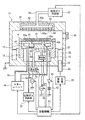
図1に、本発明の自動整合装置を好適に適用できる一例としてのプラズマ処理装置の構成を示す。このプラズマ処理装置は、RF下部2周波印加方式の容量結合型プラズマエッチング装置として構成されており、たとえばアルミニウムまたはステンレス鋼等の金属製の円筒型チャンバ(処理容器)10を有している。チャンバ10は保安接地されている。
FIG. 1 shows a configuration of a plasma processing apparatus as an example to which the automatic alignment apparatus of the present invention can be preferably applied. This plasma processing apparatus is configured as a capacitively coupled plasma etching apparatus of RF lower 2 frequency application system, and has a cylindrical chamber (processing container) 10 made of metal such as aluminum or stainless steel. The
チャンバ10内には、被処理基板としてたとえば半導体ウエハWを載置する円板状の下部電極またはサセプタ12が設けられている。このサセプタ12は、たとえばアルミニウムからなり、絶縁性の筒状保持部14を介してチャンバ10の底から垂直上方に延びる筒状支持部16に支持されている。筒状保持部14の上面には、サセプタ12の上面を環状に囲むたとえば石英やシリコンからなるフォーカスリング18が配置されている。
In the
チャンバ10の側壁と筒状支持部16との間には排気路20が形成され、この排気路20の入口または途中に環状のバッフル板22が取り付けられるとともに底部に排気口24が設けられている。この排気口24に排気管26を介して排気装置28が接続されている。排気装置28は、真空ポンプを有しており、チャンバ10内の処理空間を所定の真空度まで減圧することができる。チャンバ10の側壁には、半導体ウエハWの搬入出口を開閉するゲートバルブ30が取り付けられている。
An
サセプタ12には、プラズマ生成用の第1高周波電源32が第1整合器34および給電棒36を介して電気的に接続されている。この第1高周波電源32は、容量結合型プラズマの生成に適した所定の周波数たとえば40MHzの第1高周波RFHを出力する。第1整合器34は、第1高周波電源32と負荷(主にサセプタ、プラズマ、チャンバ)との間でインピーダンスの整合をとる。なお、チャンバ10の天井部には、後述するシャワーヘッド38が接地電位の上部電極として設けられている。したがって、第1高周波電源32からの第1の高周波はサセプタ12とシャワーヘッド38との間に容量的に印加される。
A first high
また、サセプタ12には、イオン引き込み用の第2高周波電源70が第2整合器72および給電棒36を介して電気的に接続されている。この第2高周波電源70は、サセプタ12上の半導体ウエハWに引き込まれるイオンのエネルギーを制御するのに適した所定の周波数たとえば3.2MHzの第2高周波RFLを出力する。第2整合器72は、第2高周波電源70と負荷(主にサセプタ、プラズマ、チャンバ)との間でインピーダンスの整合をとる。
The
サセプタ12の上面には半導体ウエハWを静電吸着力で保持するための静電チャック40が設けられている。この静電チャック40は導電膜からなる電極40aを一対の絶縁膜40b,40cの間に挟み込んだものであり、電極40aには直流電源42がスイッチ43を介して電気的に接続されている。直流電源42からの直流電圧により、静電気力で半導体ウエハWをチャック上に吸着保持することができる。
An
サセプタ12の内部には、たとえば円周方向に延在する冷媒室44が設けられている。この冷媒室44には、チラーユニット46より配管48、50を介して所定温度の冷媒たとえば冷却水が循環供給される。冷媒の温度によって静電チャック40上の半導体ウエハWの処理温度を制御できる。さらに、伝熱ガス供給部52からの伝熱ガスたとえばHeガスが、ガス供給ライン54を介して静電チャック40の上面と半導体ウエハWの裏面との間に供給される。
Inside the
天井部のシャワーヘッド38は、多数のガス通気孔56aを有する下面の電極板56と、この電極板56を着脱可能に支持する電極支持体58とを有する。電極支持体58の内部にバッファ室60が設けられ、このバッファ室60のガス導入口60aには処理ガス供給部62からのガス供給配管64が接続されている。
The
主制御部68は、このプラズマエッチング装置内の各部たとえば排気装置28、第1高周波電源32、第1整合器34、静電チャック用のスイッチ43、チラーユニット46、伝熱ガス供給部52、処理ガス供給部62、第2高周波電源70および第2整合器72等の動作を統括して制御する。
The
このプラズマエッチング装置において、エッチングを行うには、先ずゲートバルブ30を開状態にして加工対象の半導体ウエハWをチャンバ10内に搬入して、静電チャック40の上に載置する。そして、処理ガス供給部62よりエッチングガス(一般に混合ガス)を所定の流量および流量比でチャンバ10内に導入し、排気装置28によりチャンバ10内の圧力を設定値にする。さらに、第1高周波電源32より所定のパワーで出力される第1高周波RFHを第1整合器34を介してサセプタ12に供給すると同時に、第2高周波電源70より所定のパワーで出力される第2高周波RFLを第2整合器72を介してサセプタ12に供給する。また、伝熱ガス供給部52より静電チャック40と半導体ウエハWとの間の接触界面に伝熱ガス(Heガス)を供給するとともに、スイッチ43をオンにして直流電源42より高圧の直流電圧を静電チャック40の電極40aに印加して、静電チャック40の静電吸着力により伝熱ガスを上記接触界面に閉じ込める。シャワーヘッド38より吐出されたエッチングガスは両電極12,38間の高周波放電によってプラズマ化し、このプラズマで生成されるラジカルやイオンによって半導体ウエハWの主面がエッチングされる。
In order to perform etching in this plasma etching apparatus, first, the
このプラズマエッチング装置においては、プラズマ生成用の高周波給電部に含まれる第1整合器34およびイオン引き込み用の高周波給電部に含まれる第2整合器72のいずれにも本発明の自動整合装置を適用することができる。
In this plasma etching apparatus, the automatic matching apparatus of the present invention is applied to both the
したがって、この実施形態のプラズマエッチング装置は、第1整合器34に本発明の自動整合装置を用いることにより高速かつ精確なオートマッチングでプラズマ生成を安定かつ効率的に行えるとともに、第2整合器72に本発明の自動整合装置を用いることにより高速かつ精確なオートマッチングでイオン引き込み制御を安定かつ効率的に行うことができる。
Therefore, the plasma etching apparatus of this embodiment can stably and efficiently generate plasma by high-speed and accurate auto-matching by using the automatic matching apparatus of the present invention for the
以下、図2〜図11を参照して、このプラズマエッチング装置の第1整合器34または第2整合器72に適用した本発明の自動整合装置を説明する。
Hereinafter, the automatic alignment apparatus of the present invention applied to the
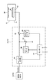
図2に、本発明の一実施形態における自動整合装置34(72)の主要な構成を示す。この自動整合装置34(72)は、整合回路内の可変リアクタンス素子として2つの可変コンデンサ80,82を有する。ここで、第1および第2可変コンデンサ80,82は、高周波電源32(70)に対して、チャンバ10側のプラズマ負荷とそれぞれ並列および直列に接続される。なお、整合回路内には、両可変コンデンサ80,82以外のインピーダンス素子、たとえばインダクタンスコイル(図示せず)が含まれてもよい。
FIG. 2 shows a main configuration of the automatic alignment apparatus 34 (72) according to the embodiment of the present invention. This automatic matching device 34 (72) has two
この自動整合装置34(72)は、オートマッチング動作を行えるように、インピーダンス測定部84、第1および第2ステッピングモータ86,88およびコントローラ90を備えている。
The automatic matching device 34 (72) includes an
インピーダンス測定部84は、整合回路の前段に設けられ、高周波電源32(70)からプラズマ負荷に給電されるRF電圧およびRF電流を測定し、RF電圧測定値とRF電流測定値とから整合回路を含む負荷側のインピーダンスZの絶対値および位相(RF電圧とRF電流の位相差)の測定値ZMm,Zθmを演算する。
The
コントローラ90は、インピーダンス測定部84より得られる負荷側インピーダンスZの絶対値測定値ZMmおよび位相測定値Zθmに応じて、絶対値測定値ZMmおよび位相測定値Zθmをそれぞれ所定の絶対値基準値ZMsおよび位相基準値Zθsに可及的または一定範囲内に近づけるように、ステップ型容量可変機構としての第1および第2ステッピングモータ86,88を介して第1および第2可変コンデンサ80,82の静電容量(容量ポジション)をステップ的に可変制御するようになっている。
この自動整合装置34(72)における整合ポイントZsは高周波電源32(70)の出力インピーダンスに等しい純抵抗値の50Ω(Zs=50+j0)に設定される。したがって、ZMs=50、Zθs=0である。 The matching point Z s in the automatic matching device 34 (72) is set to 50Ω (Z s = 50 + j0) having a pure resistance value equal to the output impedance of the high frequency power supply 32 (70). Therefore, ZM s = 50 and Zθ s = 0.
コントローラ90は、マイクロコンピュータからなり、オートマッチング動作の制御全般を司っており、主制御部68(図1)とも所要の制御信号およびデータをやりとりするようになっている。この実施形態における自動整合装置34(72)の主たる特徴は、オートマッチング動作におけるコントローラ90の機能(特に制御アルゴリズム)にある。
The
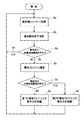
図3に、オートマッチング動作におけるコントローラ90の制御アルゴリズムの手順を示す。この自動整合装置34(72)によるオートマッチング動作は、チャンバ10内の処理対象または半導体ウエハWに対してプラズマプロセスが開始されるのと同時に開始されるのはもちろんのこと、プロセスの最中にも、いったん実質的な整合状態になって第1および第2可変コンデンサ80,82の容量ポジションを固定した後も圧力変動や外乱等によって整合が外れた時は直ちに開始または再開されるようになっている。
FIG. 3 shows the procedure of the control algorithm of the
コントローラ90は、主制御部68からの指令によって自動整合装置34(72)が稼働している間は、常に一定のサイクル毎にインピーダンス測定部84を通じて負荷側インピーダンスの絶対値測定値ZMmおよび位相測定値Zθmを取得する(ステップS1)。
While the automatic matching device 34 (72) is operating in accordance with a command from the
コントローラ90は、ソフトウェア的に、負荷側インピーダンスZの絶対値ZMおよび位相Zθを互いに直交する2つの座標軸とするインピーダンス座標系を構築することが可能であり、このインピーダンス座標上で、絶対値基準値ZMsおよび位相基準値Zθsの座標位置で表わされる整合点Zsと、絶対値測定値ZMmおよび位相測定値Zθmの座標位置で表わされる動作点Zpとを随時認識し把握することができる。ここで、動作点Zpは、第1および第2可変コンデンサ80,82の現時の静電容量(容量ポジション)C1,C2にも対応している。
The
コントローラ90は、上記のように一定サイクル毎に取得した負荷側インピーダンスZの絶対値測定値ZMmおよび位相測定値Zθmを基に、オートマッチング動作を開始または継続させる(つまり動作点Zpを移動させる)べきか、それとも終了させる(つまり動作点Zpを現在の位置に固定する)べきかの判定を行う(ステップS2)。具体的には、動作点Zpが予め整合点Zsの周りに設定された所定の内側近接範囲の中に入っているときは、動作点Zpを現在の位置に固定しておく(ステップS3→S4)。しかし、動作点Zpが上記内側近接範囲の外にあるときは、動作点Zpを移動させる処理に入る(ステップS3→S5)。
The
動作点Zpを移動させる場合は、それに先だって動作点移動制御のアルゴリズムを選定または決定する(ステップS6)。この実施形態において、コントローラ90は、2種類の整合アルゴリズムを用意しており、動作点Zpが予め整合点Zsの周りに設定された所定の外側近接範囲の中に入っているか否かに応じてそれらを使い分けるようにしている(ステップS7)。
When moving the operating point Z p is it selects or determines an algorithm of the operating point movement control prior (step S 6). In this embodiment, the
すなわち、コントローラ90は、動作点Zpが外側近接範囲の外にあるときは、第1の整合アルゴリズム(第1のマッチング制御部)を用いて、動作点Zpを整合点Zsに向けて比較的大きな歩幅でステップ移動させる(ステップS8)。そして、動作点Zpが外側近接範囲の中に入っているときは、第2の整合アルゴリズム(第2のマッチング制御部)を用いて、動作点Zpを整合点Zsに向けて比較的小さな歩幅でステップ移動させる(ステップS9)。
That is, when the operating point Z p is outside the outer proximity range, the
図4および図5につき、この実施形態における第1の整合アルゴリズム(第1のマッチング制御部)の機能を説明する。 The function of the first matching algorithm (first matching control unit) in this embodiment will be described with reference to FIGS.
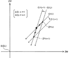
先ず、インピーダンス座標上で動作点Zpを動かす基本操作を説明する。この実施形態では、第1および第2可変コンデンサ80,82の容量ポジションC1,C2の各々を可変すると、それによって負荷側インピーダンスZの絶対値ZMおよび位相Zθの双方が変化する実際の現象を整合アルゴリズムにできるだけ忠実に盛り込むようにしている。そのための好適な一実施例として、第1可変コンデンサ80の容量ポジションC1を1ステップ可変したときの負荷側インピーダンスZの絶対値ZMおよび位相Zθの変化量δZM1,δZθ1を設定するとともに、第2可変コンデンサ82の容量ポジションC2を1ステップ可変したときの負荷側インピーダンスZの絶対値ZMおよび位相Zθの変化量δZM2,δZθ2を設定する。
First, a basic operation for moving the operating point Z p on the impedance coordinates will be described. In this embodiment, when each of the capacitance positions C 1 and C 2 of the first and second
そうすると、インピーダンス座標上で、第1可変コンデンサ80の容量ポジションC1を任意に可変すると、動作点Zpは第1の傾きR1(R1=δZθ1/δZM1)の直線上を移動し、第2可変コンデンサ82の容量ポジションC2を任意に可変すると、動作点Zpは第2の傾きR2(R2=δZθ2/δZM2)の直線上を移動することになる。
Then, if the capacitance position C 1 of the first
ここで、第1および第2可変コンデンサ80,82の容量ポジションC1,C2をそれぞれ1ステップ可変する場合に、インピーダンス座標上で動作点Zpを動かす方向性のロジックとして、図4A〜図4Bに示すような4通りのパターンが可能である。なお、C1,C2に対する負荷側インピーダンスZの絶対値ZMおよび位相Zθの変化率は負であるとする。すなわち、C1,C2の各々を正方向に1ステップ(+1)可変すると、絶対値測定値ZMmおよび位相測定値Zθmのいずれも減少する方向に動作点Zpが移動し、C1,C2の各々を負方向に1ステップ(−1)可変すると、絶対値測定値ZMmおよび位相測定値Zθmのいずれも増大する方向に動作点Zpが移動するものとする。また、C1を先に1ステップ可変し、C2を後に1ステップ可変するものとする。
Here, in the case where the capacitance positions C 1 and C 2 of the first and second
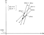
図4Aは、C1を+1可変し、C2を+1可変した場合である(ΔC1=+1,ΔC2=+1)。この場合、C1の+1可変によりC2座標軸はC2(j)から左上のC2(j+1)へ1ピッチ移動するとともに、C2の+1可変によりC1座標軸はC1(i)から右下のC1(i+1)へ1ピッチ移動し、動作点はC1(i)とC2(j)との交点Zp(k)からC1(i+1)とC2(j+1)との交点Zp(k+1)へ移動する。 FIG. 4A shows a case where C 1 is changed by +1 and C 2 is changed by +1 (ΔC 1 = + 1, ΔC 2 = + 1). In this case, the plus variable C 1 with C 2 axes are one pitch movement from C 2 (j) to the upper left C 2 (j + 1), C 1 coordinate axis C 1 by +1 variable C 2 (i) one pitch movement to C 1 at the lower right (i + 1) from the operating point C 1 (i) and C 2 from the intersection of the (j) Z p (k) C 1 (i + 1) and C 2 Move to the intersection Z p (k + 1) with (j + 1).
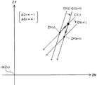
図4Bは、C1を+1可変し、C2を−1可変した場合である(ΔC1=+1,ΔC2=−1)。この場合、C1の+1可変によりC2座標軸はC2(j)から左上のC2(j+1)へ1ピッチ移動するとともに、C2の−1可変によりC1座標軸はC1(i)から左上のC1(i+1)へ1ピッチ移動し、動作点はC1(i)とC2(j)との交点Zp(k)からC1(i+1)とC2(j+1)との交点Zp(k+1)へ移動する。 FIG. 4B shows a case where C 1 is varied by +1 and C 2 is varied by −1 (ΔC 1 = + 1, ΔC 2 = −1). In this case, the plus variable C 1 with C 2 axes are one pitch movement from C 2 (j) to the upper left C 2 (j + 1), C 1 coordinate axis by -1 variable C 2 is C 1 (i ) from one pitch movement the upper left to the C 1 (i + 1), the operating point C 1 (i) and C 2 (from the intersection of the j) Z p (k) C 1 (i + 1) and C 2 Move to the intersection Z p (k + 1) with (j + 1).
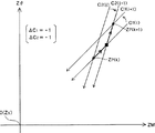
図4Cは、C1を−1可変し、C2を+1可変した場合である(ΔC1=−1,ΔC2=+1)。この場合、C1の−1可変によりC2座標軸はC2(j)から右下のC2(j+1)へ1ピッチ移動するとともに、C2の+1可変によりC1座標軸はC1(i)から右下のC1(i+1)へ1ピッチ移動し、動作点はC1(i)とC2(j)との交点Zp(k)からC1(i+1)とC2(j+1)との交点Zp(k+1)へ移動する。 FIG. 4C shows a case where C 1 is changed by −1 and C 2 is changed by +1 (ΔC 1 = −1, ΔC 2 = + 1). In this case, the C 2 coordinate axis by -1 variable C 1 is moved C 2 (j + 1) to one pitch of the lower right from C 2 (j), C 1 coordinate axis by +1 variable C 2 is C 1 ( Move from i) to C 1 (i + 1) in the lower right by one pitch, and the operating point is from the intersection Z p (k) of C 1 (i) and C 2 (j) to C 1 (i + 1). Move to the intersection Z p (k + 1) with C 2 (j + 1).
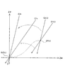
図4Dは、C1を−1可変し、C2を−1可変した場合である(ΔC1=−1,ΔC2=−1)。この場合、C1の−1可変によりC2座標軸はC2(j)から右下のC2(j+1)へ1ピッチ移動するとともに、C2の−1可変によりC1座標軸はC1(i)から左上のC1(i+1)へ1ピッチ移動し、動作点はC1(i)とC2(j)との交点Zp(k)からC1(i+1)とC2(j+1)との交点Zp(k+1)へ移動する。 FIG. 4D shows a case where C 1 is varied by −1 and C 2 is varied by −1 (ΔC 1 = −1, ΔC 2 = −1). In this case, the C 2 coordinate axis by -1 variable C 1 is one pitch movement from C 2 (j) to C 2 at the lower right (j + 1), C 1 coordinate axis by -1 variable C 2 is C 1 Move from (i) to C 1 (i + 1) in the upper left, and the operating point is from the intersection Z p (k) between C 1 (i) and C 2 (j) to C 1 (i + 1). Move to the intersection Z p (k + 1) with C 2 (j + 1).
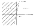
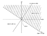
この実施形態における第1の整合アルゴリズムは、上記のような動作点Zpを動かす4通りの基本移動パターン(図4A〜図4D)の中で2番目(図4B)を用いる。すなわち、図5に示すように、理想的には、C1座標軸およびC2座標軸が共に原点O(整合点Zs)通るときに、動作点Zpが整合点Zsに一致し、完全に整合がとれた状態になる。この観点から、第1の整合アルゴリズムでは、原点O(整合点Zs)を通るC1座標軸およびC2座標軸をそれぞれ第1および第2基準線C1S,C2Sとし、一定のサイクル毎に現時のC1座標軸C1(i) (ひいては動作点Zp)を第1基準線C1Sに近づける方向にC2を1ステップ可変し、一定のサイクル毎に現時のC2座標軸C2(j) ひいては動作点Zp)を第2基準線C2Sに近づける方向にC1を1ステップ可変するようにしており、そのためには2番目(図4B)の基本移動パターン(ΔC1=+1,ΔC2=−1)を採択すればよい。 The first matching algorithm in this embodiment uses the second (FIG. 4B) among the four basic movement patterns (FIGS. 4A to 4D) for moving the operating point Z p as described above. That is, as shown in FIG. 5, ideally, when both the C 1 coordinate axis and the C 2 coordinate axis pass through the origin O (alignment point Z s ), the operating point Z p coincides with the alignment point Z s and is completely It will be in a consistent state. From this point of view, in the first alignment algorithm, the C 1 coordinate axis and the C 2 coordinate axis passing through the origin O (alignment point Z s ) are set as the first and second reference lines C 1S and C 2S , respectively, and the current time is set every fixed cycle. C 1 coordinate axis C 1 (i) (and hence the operating point Z p ) is varied by one step so that C 2 is closer to the first reference line C 1S , and the current C 2 coordinate axis C 2 (j) is changed every fixed cycle. As a result, C 1 is varied by one step so that the operating point Z p ) approaches the second reference line C 2S , and for this purpose, the second basic movement pattern (ΔC 1 = + 1, ΔC 2) is used. = -1) may be adopted.
この基本移動パターン(ΔC1=+1,ΔC2=−1)は、制御ロジックとして次の演算式(1),(2)を用いる。
ΔC1=[R2・ZM−Zθ]=±1 ・・・(1)
ΔC2=[−R1・ZM+Zθ]=±1 ・・・(2)
This basic movement pattern (ΔC 1 = + 1, ΔC 2 = −1) uses the following arithmetic expressions (1) and (2) as control logic.
ΔC 1 = [R 2 · ZM−Zθ] = ± 1 (1)
ΔC 2 = [− R 1 · ZM + Zθ] = ± 1 (2)
ここで、上記の演算式(1)は、R2・ZM−Zθの値が正のときはΔC1=+1となり、R2・ZM−Zθの値が負のときはΔC1=−1となることを意味する。つまり、図6Aに示すように、インピーダンス座標上で第2基準線C2Sにより分割される2つの領域(無地領域/斜線領域)のうち、動作点Zpが右側の無地領域内に位置しているときは、R2・ZM−Zθの値が正であり、ΔC1=+1の1ステップ可変制御が選択され、動作点Zpが左側の斜線領域内に位置しているときは、R2・ZM−Zθの値が負であり、ΔC1=−1の1ステップ可変制御が選択される。どちらの場合でも、ΔC1の1ステップ可変制御により、現時のC2座標軸C2(j)は第2基準線C2Sに近づく方向に1ピッチ移動することになる。 Here, when the value of R 2 · ZM−Zθ is positive, ΔC 1 = + 1 when the value of R 2 · ZM−Zθ is positive, and ΔC 1 = −1 when the value of R 2 · ZM−Zθ is negative. It means to become. That is, as shown in FIG. 6A, the operating point Z p is located in the right plain region among the two regions (solid region / hatched region) divided by the second reference line C 2S on the impedance coordinate. When the value of R 2 · ZM−Zθ is positive, 1 -step variable control of ΔC 1 = + 1 is selected, and the operating point Z p is located in the shaded area on the left side, R 2 The value of ZM−Zθ is negative, and one -step variable control with ΔC 1 = −1 is selected. In either case, the current C 2 coordinate axis C 2 (j) is moved by one pitch in the direction approaching the second reference line C 2S by the one-step variable control of ΔC 1 .
また、上記の演算式(2)は、−R1・ZM+Zθの値が正のときはΔC2=+1となり、−R1・ZM+Zθの値が負のときはΔC2=−1となることを意味する。つまり、図6Bに示すように、インピーダンス座標上で第1基準線C1Sにより分割される2つの領域(無地領域/斜線領域)のうち、動作点Zpが右側の無地領域内に位置しているときは、−R1・ZM+Zθの値が負で、ΔC2=−1の1ステップ可変制御が選択され、動作点Zpが左側の斜線領域内に位置しているときは、−R1・ZM+Zθの値が正で、ΔC2=+1の1ステップ可変制御が選択される。どちらの場合でも、ΔC2の1ステップ可変制御によって、現時のC1座標軸C1(i)は第1基準線C1Sに近づく方向に1ピッチ移動することになる。 Further, the arithmetic expression (2) is, -R 1 · ZM + when the value of Z.theta is positive [Delta] C 2 = + 1, and the to be a [Delta] C 2 = -1 when the value of -R 1 · ZM + Zθ is negative means. That is, as shown in FIG. 6B, the operating point Z p is located in the right plain region among the two regions (solid region / hatched region) divided by the first reference line C 1S on the impedance coordinate. when you are in a negative value of -R 1 · ZM + Z.theta, is selected 1 step variable control of [Delta] C 2 = -1, when the operating point Z p is located on the left side of the shaded area is, -R 1 A one-step variable control with a positive value of ZM + Zθ and ΔC 2 = + 1 is selected. In either case, the current C 1 coordinate axis C 1 (i) moves by one pitch in the direction approaching the first reference line C 1S by the one-step variable control of ΔC 2 .
第1の整合アルゴリズムにおいて重要なことは、演算式(1),(2)が非常に簡単であり、しかもテーブルを用いないため、演算処理ひいては動作点移動処理(ステップS8)を短時間で高速に行えるということである。 What is important in the first matching algorithm is that the arithmetic expressions (1) and (2) are very simple and do not use a table, so that the arithmetic processing and consequently the operating point movement processing (step S 8 ) can be performed in a short time. That means it can be done at high speed.
また、上記の例(図4A〜図4D)では、一見すると、図4Bの基本移動パターンを用いるよりは図4Aの基本移動パターン(ΔC1=+1,ΔC2=+1)を用いた方が動作点Zpを原点O(整合点Zs)に近づけられるようにも思われる。しかし、局所的な場面ではそうであっても、図4Aの基本移動パターンを使用すると、C1座標軸C1(i)が第1基準線C1Sから離れる方向(右下)に移動するので、結果的に整合点への収束は望めない。 In the above example (FIGS. 4A to 4D), at first glance, the operation using the basic movement pattern (ΔC 1 = + 1, ΔC 2 = + 1) of FIG. 4A is more effective than the basic movement pattern of FIG. 4B. It seems that the point Z p can be brought close to the origin O (alignment point Z s ). However, even in a local scene, if the basic movement pattern of FIG. 4A is used, the C 1 coordinate axis C 1 (i) moves away from the first reference line C 1S (lower right). As a result, convergence to the matching point cannot be expected.
図7につき、具体例を用いて、第1の整合アルゴリズム(第1のマッチング制御部)による動作点移動処理(ステップS8)の作用をより詳細に説明する。 With reference to FIG. 7, the operation of the operating point moving process (step S 8 ) by the first matching algorithm (first matching control unit) will be described in more detail using a specific example.
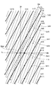
この例では、第1可変コンデンサ80の容量ポジションC1を1ステップ可変したときの負荷側インピーダンスZの絶対値ZMおよび位相Zθの変化量δZM1,δZθ1を−1,−2に設定し、C1座標軸の傾き(第1の傾き)R1を2としている。また、第2可変コンデンサ82の容量ポジションC2を1ステップ可変したときの負荷側インピーダンスZの絶対値ZMおよび位相Zθの変化量δZM2,δZθ2を−2,−6に設定し、C2座標軸の傾き(第2の傾き)R2を3としている。
In this example, the absolute value ZM of the load side impedance Z and the change amounts δZM 1 and δZθ 1 of the phase Zθ when the capacitance position C 1 of the first
この場合、C1座標軸C1(i),C1(i+1),・・の絶対値ZM軸上の間隔は1で、位相Zθ軸上の間隔は2である。一方、C2座標軸C2(j),C1(j+1),・・の絶対値ZM軸上の間隔は1/3で、位相Zθ軸上の間隔は1である。また、上記演算式(1),(2)は次のようになる。
ΔC1=[3ZM−Zθ]=±1 ・・・(1)'
ΔC2=[−2ZM+Zθ]=±1 ・・・(2)'
In this case, the interval on the absolute value ZM axis of the C 1 coordinate axes C 1 (i), C 1 (i + 1),... Is 1, and the interval on the phase Zθ axis is 2. On the other hand, the interval on the absolute value ZM axis of the C 2 coordinate axes C 2 (j), C 1 (j + 1),... Is 1/3, and the interval on the phase Zθ axis is 1. Also, the arithmetic expressions (1) and (2) are as follows.
ΔC 1 = [3ZM−Zθ] = ± 1 (1) ′
ΔC 2 = [− 2ZM + Zθ] = ± 1 (2) ′
また、この具体例では、ΔC1の感度(ゲイン)とΔC2の感度(ゲイン)との間でバランスをとるために、比較的小さい間隔のC2座標軸を移動させる方のC1を1サイクル毎に1ステップ可変し、比較的大きい間隔のC2座標軸を移動させる方のC2を2サイクル毎に1ステップ可変するようにしている。 Further, in this specific example, in order to balance between the sensitivity (gain) of ΔC 1 and the sensitivity (gain) of ΔC 2 , one cycle of C 1 that moves the C 2 coordinate axis with a relatively small interval is performed in one cycle. 1 step variable and are to be one step varying the C 2 towards moving the C 2 axis of relatively large intervals every 2 cycles for each.
図7において、第1の動作点Zp(1)がC1座標軸C1(3)とC2座標軸C2(6)との交点にあり、その座標位置(ZMm,Zθm)が(1.5,−2)であるとする。 In FIG. 7, the first operating point Z p (1) is at the intersection of the C 1 coordinate axis C 1 (3) and the C 2 coordinate axis C 2 (6), and the coordinate position (ZM m , Zθ m ) is ( 1.5, -2).
(1) この場合、第1サイクルでは、次のような演算結果が得られる。
ΔC1=[3×1.5−(−2)]=[6.5]>0⇒+1
ΔC2=[−2×1.5+(−2)]=[−5]<0⇒−1
(1) In this case, the following calculation result is obtained in the first cycle.
ΔC 1 = [3 × 1.5 − (− 2)] = [6.5]> 0⇒ + 1
ΔC 2 = [− 2 × 1.5 + (− 2)] = [− 5] <0⇒−1
この演算結果にしたがって、ΔC1=+1の1ステップ可変制御とΔC2=−1の1ステップ可変制御とが実行される。その結果、C2座標軸はC2(6)から左上に1ピッチ隣のC2(7)へ移動するとともに、C1座標軸はC1(3)から左上に1ピッチ隣のC1(4)へ移動し、動作点ZpはC1(4)とC2(7)との交点Zp(2)へ移動する。この移動先の動作点Zp(2)の座標位置(ZMm,Zθm)は(2.5,2)である。 According to this calculation result, one -step variable control of ΔC 1 = + 1 and one-step variable control of ΔC 2 = −1 are executed. As a result, the C 2 coordinate axis moves from C 2 (6) to C 2 (7) adjacent to the upper left by 1 pitch, and the C 1 coordinate axis moves from C 1 (3) to C 1 (4) adjacent to the upper left by 1 pitch. The operating point Z p moves to the intersection Z p (2) between C 1 (4) and C 2 (7). The coordinate position (ZM m , Zθ m ) of the movement point Z p (2) is (2.5, 2).
(2) 直後の第2サイクルでは、次のような演算結果が得られる。
ΔC1=[3×2.5−2]=[5.5]>0⇒+1
(2) In the second cycle immediately after, the following calculation result is obtained.
ΔC 1 = [3 × 2.5-2] = [5.5]> 0⇒ + 1
この演算結果にしたがって、ΔC1=+1の1ステップ可変制御が実行される。その結果、C2座標軸はC2(7)から左上に1ピッチ隣のC2(8)へ移動し、動作点ZpはC1(4)とC2(8)との交点Zp(3)へ移動する。この移動先の動作点Zp(3)の座標位置(ZMm,Zθm)は(1.5,0)である。 According to this calculation result, one -step variable control of ΔC 1 = + 1 is executed. As a result, the C 2 coordinate axis moves from C 2 (7) to C 2 (8), which is one pitch next to the upper left, and the operating point Z p is the intersection Z p (C 1 (4) and C 2 (8)). Move to 3). The coordinate position (ZM m , Zθ m ) of the movement destination operating point Z p (3) is (1.5, 0).
(3) 直後の第3サイクルでは、次のような演算結果が得られる。
ΔC1=[3×1.5−0]=[4.5]>0⇒+1
ΔC2=[−2×1.5+0]=[−3]<0⇒−1
(3) In the third cycle immediately after, the following calculation result is obtained.
ΔC 1 = [3 × 1.5−0] = [4.5]> 0⇒ + 1
ΔC 2 = [− 2 × 1.5 + 0] = [− 3] <0⇒−1
この演算結果にしたがって、ΔC1=+1の1ステップ可変制御とΔC2=−1の1ステップ可変制御とが実行される。その結果、C2座標軸はC2(8)から左上に1ピッチ隣のC2(9)へ移動するとともに、C1座標軸はC1(4)から左上に1ピッチ隣のC1(5)へ移動し、動作点ZpはC1(5)とC2(9)との交点Zp(4)へ移動する。この移動先の動作点Zp(4)の座標位置(ZMm,Zθm)は(2.5,4)である。 According to this calculation result, one -step variable control of ΔC 1 = + 1 and one-step variable control of ΔC 2 = −1 are executed. As a result, the C 2 coordinate axis moves from C 2 (8) to C 2 (9) adjacent to the upper left by 1 pitch, and the C 1 coordinate axis moves from C 1 (4) to C 1 (5) adjacent to the upper left by 1 pitch. The operating point Z p moves to the intersection Z p (4) between C 1 (5) and C 2 (9). The coordinate position (ZM m , Zθ m ) of the movement destination operating point Z p (4) is (2.5, 4).
(4) 直後の第4サイクルでは、次のような演算結果が得られる。
ΔC1=[3×2.5−4]=[3.5]>0⇒+1
(4) In the fourth cycle immediately after, the following calculation result is obtained.
ΔC 1 = [3 × 2.5−4] = [3.5]> 0⇒ + 1
この演算結果にしたがって、ΔC1=+1の1ステップ可変制御が実行される。その結果、C2座標軸はC2(9)から左上に1ピッチ隣のC2(10)へ移動し、動作点ZpはC1(5)とC2(10)との交点Zp(5)へ移動する。この移動先の動作点Zp(5)の座標位置(ZMm,Zθm)は(1.5,2)である。 According to this calculation result, one -step variable control of ΔC 1 = + 1 is executed. As a result, the C 2 coordinate axis moves from C 2 (9) to C 2 (10), which is one pitch next to the upper left, and the operating point Z p is the intersection Z p (C 1 (5) and C 2 (10)). Move to 5). The coordinate position (ZM m , Zθ m ) of the movement destination operating point Z p (5) is (1.5, 2).
(5) 直後の第5サイクルでは、次のような演算結果が得られる。
ΔC1=[3×1.5−2]=[2.5]>0⇒+1
ΔC2=[−2×1.5+2]=[−1]<0⇒−1
(5) In the fifth cycle immediately after, the following calculation result is obtained.
ΔC 1 = [3 × 1.5-2] = [2.5]> 0⇒ + 1
ΔC 2 = [− 2 × 1.5 + 2] = [− 1] <0⇒−1
この演算結果にしたがって、ΔC1=+1の1ステップ可変制御とΔC2=−1の1ステップ可変制御とが実行される。その結果、C2座標軸はC2(10)から左上に1ピッチ隣のC2(11)へ移動するとともに、C1座標軸はC1(5)から左上に1ピッチ隣のC1(6)へ移動し、動作点ZpはC1(6)とC2(11)との交点Zp(6)へ移動する。この移動先の動作点Zp(6)の座標位置(ZMm,Zθm)は(2.5,6)である。 According to this calculation result, one -step variable control of ΔC 1 = + 1 and one-step variable control of ΔC 2 = −1 are executed. As a result, the C 2 coordinate axis moves from C 2 (10) to C 2 (11) adjacent to the upper left by 1 pitch, and the C 1 coordinate axis moves from C 1 (5) to C 1 (6) adjacent to the upper left by 1 pitch. The operating point Z p moves to the intersection Z p (6) between C 1 (6) and C 2 (11). The coordinate position (ZM m , Zθ m ) of the movement destination operating point Z p (6) is (2.5, 6).
(6) 直後の第6サイクルでは、次のような演算結果が得られる。
ΔC1=[3×2.5−6]=[1.5]>0⇒+1
(6) In the sixth cycle immediately after, the following calculation result is obtained.
ΔC 1 = [3 × 2.5−6] = [1.5]> 0⇒ + 1
この演算結果にしたがって、ΔC1=+1の1ステップ可変制御が実行される。その結果、C2座標軸はC2(11)から左上に1ピッチ隣のC2(12)へ移動し、動作点ZpはC1(6)とC2(12)との交点Zp(7)へ移動する。この移動先の動作点Zp(7)の座標位置(ZMm,Zθm)は(1.5,4)である。 According to this calculation result, one -step variable control of ΔC 1 = + 1 is executed. As a result, the C 2 coordinate axis moves from C 2 (11) to C 2 (12) adjacent to one pitch in the upper left, and the operating point Z p is the intersection Z p (C 1 (6) and C 2 (12)). Move to 7). The coordinate position (ZM m , Zθ m ) of the movement destination operating point Z p (7) is (1.5, 4).
上記のように、第1の整合アルゴリズム(第1のマッチング制御部)による動作点移動処理(ステップS8)を一定サイクルで繰り返し実行することにより、C1座標軸をC1(3)→C1(4)→C1(5) →C1(6)と第1基準線C1Sに近づけるとともに、C2座標軸をC2(6)→C2(7)→C2(8) →C2(9)→C2(10) →C2(11) →C2(12)と第2基準線C2Sに近づけ、ひいては動作点ZpをZp(1)→Zp(2)→Zp(3) →Zp(4)→Zp(5)→Zp(6) →Zp(7)と蛇行させながらも着実に原点O(整合点ZS)に近づけることができる。 As described above, the operating point movement process (step S 8 ) by the first matching algorithm (first matching control unit) is repeatedly executed in a fixed cycle, whereby the C 1 coordinate axis is changed to C 1 (3) → C 1. (4) → C 1 (5) → C 1 (6) and the first reference line C 1S , and the C 2 coordinate axis C 2 (6) → C 2 (7) → C 2 (8) → C 2 (9) → C 2 (10) → C 2 (11) → C 2 (12) and the second reference line C 2S , and the operating point Z p is set to Z p (1) → Z p (2) → Z It is possible to steadily approach the origin O (alignment point Z S ) while meandering as p (3) → Z p (4) → Z p (5) → Z p (6) → Z p (7).
しかしながら、この先も第1の整合アルゴリズム(第1のマッチング制御部)を使い続けると、図8に示すように、動作点Zpは原点O(整合点ZS)の近傍に収束させることはできなくなる。 However, if the first matching algorithm (first matching control unit) continues to be used in the future, the operating point Z p cannot converge to the vicinity of the origin O (matching point Z S ) as shown in FIG. Disappear.
(7) すなわち、第1の整合アルゴリズム(第1のマッチング制御部)にしたがえば、次の第7サイクルでは、次のような演算結果が得られる。
ΔC1=[3×1.5−4]=[0.5]>0⇒+1
ΔC2=[−2×1.5+4]=[1]>0⇒+1
(7) That is, according to the first matching algorithm (first matching control unit), the following calculation result is obtained in the next seventh cycle.
ΔC 1 = [3 × 1.5−4] = [0.5]> 0⇒ + 1
ΔC 2 = [− 2 × 1.5 + 4] = [1]> 0⇒ + 1
この演算結果にしたがって、ΔC1=+1の1ステップ可変制御とΔC2=+1の1ステップ可変制御とが実行される。その結果、C2座標軸はC2(12)から左上に1ピッチ隣のC2(13)へ移動するとともに、C1座標軸はC1(6)から右下に1ピッチ隣のC1(5)へ移動し、動作点ZpはC1(5)とC2(13)との交点Zp(8)へ移動する。この移動先の動作点Zp(8)の座標位置(ZMm,Zθm)は(−1.5,−4)である。 According to this calculation result, one -step variable control of ΔC 1 = + 1 and one-step variable control of ΔC 2 = + 1 are executed. As a result, the C 2 coordinate axis moves from C 2 (12) to C 2 (13) adjacent to the upper left by 1 pitch, and the C 1 coordinate axis moves from C 1 (6) to C 1 (5 adjacent to the 1 pitch adjacent to the lower right. ) And the operating point Z p moves to the intersection Z p (8) between C 1 (5) and C 2 (13). The coordinate position (ZM m , Zθ m ) of the movement destination operating point Z p (8) is (−1.5, −4).
(8) そして、直後の第8サイクルでは、次のような演算結果が得られる。
ΔC1=[3×(−1.5)−(−4)]=[−0.5]<0⇒−1
(8) Then, in the immediately following eighth cycle, the following calculation result is obtained.
ΔC 1 = [3 × (−1.5) − (− 4)] = [− 0.5] <0⇒−1
この演算結果にしたがって、ΔC1=−1の1ステップ可変制御が実行される。その結果、C2座標軸はC2(13)から右下に1ピッチ隣のC2(12)へ移動し、動作点ZpはC1(5)とC2(12)との交点Zp(9)へ移動する。この移動先の動作点Zp(9)の座標位置(ZMm,Zθm)は(−0.5,−2)である。 According to this calculation result, one -step variable control with ΔC 1 = −1 is executed. As a result, the C 2 coordinate axis moves from C 2 (13) to C 2 (12), which is one pitch down in the lower right, and the operating point Z p is the intersection Z p between C 1 (5) and C 2 (12). Move to (9). The coordinate position (ZM m , Zθ m ) of this movement destination operating point Z p (9) is (−0.5, −2).
(9) さらに、直後の第9サイクルでは、次のような演算結果が得られる。
ΔC1=[3×(−0.5)−(−2)]=[0.5]>0⇒+1
ΔC2=[−2×(−0.5)+(−2)]=[−1]<0⇒−1
(9) Further, in the ninth cycle immediately after, the following calculation result is obtained.
ΔC 1 = [3 × (−0.5) − (− 2)] = [0.5]> 0⇒ + 1
ΔC 2 = [− 2 × (−0.5) + (− 2)] = [− 1] <0⇒−1
この演算結果にしたがって、ΔC1=+1の1ステップ可変制御とΔC2=−1の1ステップ可変制御とが実行される。その結果、C2座標軸はC2(12)から左上に1ピッチ隣のC2(13)へ移動するとともに、C1座標軸はC1(5)から左上に1ピッチ隣のC1(6)へ移動し、動作点ZpはC1(6)とC2(13)との交点Zp(10)へ移動する。この移動先の動作点Zp(10)の座標位置(ZMm,Zθm)は(0.5,2)である。 According to this calculation result, one -step variable control of ΔC 1 = + 1 and one-step variable control of ΔC 2 = −1 are executed. As a result, the C 2 coordinate axis moves from C 2 (12) to C 2 (13) adjacent to the upper left by 1 pitch, and the C 1 coordinate axis moves from C 1 (5) to C 1 (6) adjacent to the upper left by 1 pitch. The operating point Z p moves to the intersection Z p (10) between C 1 (6) and C 2 (13). The coordinate position (ZM m , Zθ m ) of the movement point Z p (10) is (0.5, 2).
(10) さらに、直後の第10サイクルでは、次のような演算結果が得られる。
ΔC1=[3×0.5−2]=[−0.5]<0⇒−1
(10) Further, in the 10th cycle immediately after, the following calculation result is obtained.
ΔC 1 = [3 × 0.5-2] = [− 0.5] <0⇒−1
この演算結果にしたがって、ΔC1=−1の1ステップ可変制御が実行される。その結果、C2座標軸はC2(13)から右下に1ピッチ隣のC2(12)へ移動し、動作点ZpはC1(6)とC2(12)との交点Zp(11)へ移動する。この移動先の動作点Zp(11)の座標位置(ZMm,Zθm)は(1.5,4)であり、第6サイクルで移動した時の動作点Zp(7)の位置に戻ることになる。 According to this calculation result, one -step variable control with ΔC 1 = −1 is executed. As a result, the C 2 coordinate axis moves from C 2 (13) to C 2 (12) next to one pitch in the lower right, and the operating point Z p is the intersection Z p between C 1 (6) and C 2 (12). Move to (11). The coordinate position (ZM m , Zθ m ) of this movement destination operating point Z p (11) is (1.5, 4), which is the position of the operating point Z p (7) when moving in the sixth cycle. Will return.
こうして、第1の整合アルゴリズム(第1のマッチング制御部)を使い続けたならば、動作点ZpはZp(7)→Zp(8) →Zp(9)→Zp(10)→Zp(11)のルートを延々と循環移動するだけであり、原点O(整合点ZS)にそれ以上近づくことは決してできない。 Thus, if the first matching algorithm (first matching control unit) is continuously used, the operating point Z p becomes Z p (7) → Z p (8) → Z p (9) → Z p (10). → The route of Z p (11) is merely circulated endlessly, and the origin O (alignment point Z S ) can never be approached any further.
この具体例の場合、C2のステップ可変に応じて移動するC1座標軸およびC1のステップ可変に応じて移動するC2座標軸はいずれも原点O(整合点ZS)を跨ぎ、それぞれ第1および第2基準線C1S,C2Sと重なることはないので、動作点Zpを原点O(整合点ZS)に正確に一致させることはできない。つまり、完全な整合状態は元々望めない。 In this embodiment, C 1 coordinate axis and C 2 axis which moves in response to the step variable C 1 are both straddle the origin O (matching point Z S), a respective one moves in response to the step variable C 2 Since the second reference lines C 1S and C 2S do not overlap with each other, the operating point Z p cannot be accurately matched with the origin O (alignment point Z S ). In other words, a perfect alignment state cannot be originally expected.
しかし、C1座標軸のC1(5)とC2座標軸のC2(11)との交点ZA(0.5,0)およびC1座標軸のC1(6)とC2座標軸のC2(14)との交点ZB(−0.5,0)が原点O(整合点ZS)のごく近傍に位置している。動作点Zpをこれらの交点ZA,ZBのどちらかに収束させることは可能であり(この自動整合装置の実力範囲内であり)、それによって完全整合状態と実用的に等価な状態(実質的な整合状態)を得ることができる。すなわち、この具体例において、動作点Zpを原点O(整合点ZS)に可及的または所定の内側近接範囲内に近づけるということは、動作点ZpをZA,ZBのどちらかに着かせることに他ならない。 However, C 1 coordinate axis C 1 (5) and C 2 coordinate axis of C 2 (11) intersection between Z A (0.5, 0) and C 1 coordinate axis C 1 (6) and C 2 coordinate axis of C 2 The intersection Z B (−0.5, 0) with (14) is located very close to the origin O (alignment point Z S ). It is possible to converge the operating point Z p to either of these intersections Z A , Z B (within the range of capability of this automatic alignment device), so that a state that is practically equivalent to the perfect alignment state ( A substantial alignment state). That is, in this embodiment, the fact that closer the operating point Z p in as much as possible or a predetermined inner proximity range to the origin O (matching point Z S) is either the operating point Z p Z A, the Z B It ’s nothing but to put on.
この実施形態において、コントローラ90は、動作点Zpが上記循環ルートに入ると、整合アルゴリズム選定処理(ステップS6)により、そのことを検出し、動作点Zpが予め設定した外側近接範囲内に入ったものと判定して(ステップS7)、第1の整合アルゴリズム(第1のマッチング制御部)から第2の整合アルゴリズム(第2のマッチング制御部)に切り換える(ステップS7→S9)。
In this embodiment, when the operating point Z p enters the circulation route, the
以下、図9および図10につき、この実施形態における第2の整合アルゴリズム(第2のマッチング制御部)の機能を説明する。 Hereinafter, the function of the second matching algorithm (second matching control unit) in this embodiment will be described with reference to FIGS. 9 and 10.
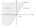
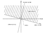
この第2の整合アルゴリズムでは、インピーダンス座標上で、第1および第2基準線C1S,C2Sとそれぞれ直交する第3の基準線TC1S,TC2Sを定義し、基準線TC1SまたはTC2Sを動作点移動制御の目標にして、C1座標軸またはC2座標軸上で動作点Zpを移動させる。 In the second matching algorithm, on the impedance coordinates, the first and second reference line C 1S, C 2S and the third reference line TC 1S perpendicular respectively, define the TC 2S, reference line TC 1S or TC 2S Is the target of the operation point movement control, and the operation point Z p is moved on the C 1 coordinate axis or the C 2 coordinate axis.
たとえば、基準線TC1Sを目標にして、C1座標軸上で動作点Zpを移動させる場合は、次の演算式(3)を用いる。
ΔC1=[ZM+R1・Zθ]=±1 ・・・(3)
For example, when the operating point Z p is moved on the C 1 coordinate axis with the reference line TC 1S as a target, the following arithmetic expression (3) is used.
ΔC 1 = [ZM + R 1 · Zθ] = ± 1 (3)
ここで、上記の演算式(3)は、ZM+R1・Zθの値が正のときはΔC1=+1となり、ZM+R1・Zθの値が負のときはΔC1=−1となることを意味する。つまり、図9Aに示すように、インピーダンス座標上で基準線TC1Sにより分割される2つの領域(無地領域/斜線領域)のうち、動作点Zpが右側の斜線領域内に位置しているときは、ZM+R1・Zθの値が正で、ΔC1=+1の1ステップ可変制御が選択され、動作点Zpが左側の無地領域内に位置しているときは、ZM+R1・Zθの値が負で、ΔC1=−1の1ステップ可変制御が選択される。 Here, the arithmetic expression (3), means that the value of ZM + R 1 · Zθ becomes [Delta] C 1 = -1 when positive ΔC 1 = + 1 next to the time, the value of ZM + R 1 · Zθ negative To do. That is, as shown in FIG. 9A, when the operating point Z p is located in the right hatched area of the two areas (solid area / hatched area) divided by the reference line TC 1S on the impedance coordinate. When ZM + R 1 · Zθ is positive and 1 -step variable control of ΔC 1 = + 1 is selected, and the operating point Z p is located in the left plain region, the value of ZM + R 1 · Zθ is A negative one -step variable control with ΔC 1 = −1 is selected.
また、基準線TC2Sを目標にして、C2座標軸上で動作点Zpを移動させる場合は、次の演算式(4)を用いる。
ΔC2=[ZM+R2・Zθ]=±1 ・・・(4)
Further, when the operating point Z p is moved on the C 2 coordinate axis with the reference line TC 2S as a target, the following arithmetic expression (4) is used.
ΔC 2 = [ZM + R 2 · Zθ] = ± 1 (4)
ここで、上記の演算式(4)は、ZM+R2・Zθの値が正のときはΔC2=+1となり、ZM+R2・Zθの値が負のときはΔC2=−1となることを意味する。つまり、図9Bに示すように、インピーダンス座標上で基準線TC2Sにより分割される2つの領域(無地領域/斜線領域)のうち、動作点Zpが右側の斜線領域内に位置しているときは、ZM+R2・Zθの値が正で、ΔC2=+1の1ステップ可変制御が選択され、動作点Zpが左側の無地領域内に位置しているときは、ZM+R2・Zθの値が負で、ΔC2=−1の1ステップ可変制御が選択される。 Here, the above equation (4) means that ΔC 2 = + 1 when the value of ZM + R 2 · Zθ is positive, and ΔC 2 = −1 when the value of ZM + R 2 · Zθ is negative. . That is, as shown in FIG. 9B, when the operating point Z p is located in the right hatched area of the two areas (solid area / hatched area) divided by the reference line TC 2S on the impedance coordinate. When ZM + R 2 · Zθ has a positive value and ΔC 2 = + 1 one-step variable control is selected, and the operating point Z p is located in the left plain region, the value of ZM + R 2 · Zθ is A negative one-step variable control with ΔC 2 = −1 is selected.
上記の例(図7)の場合は、1ステップ当たりの動作点Zpの移動距離は、C2座標軸上よりもC1座標軸上の方が小さいので、C1座標軸と直交する基準線TC1Sを移動目標とするロジックを用いるのが好ましい。 In the case of the above example (FIG. 7), the movement distance of the operating point Z p per step is smaller on the C 1 coordinate axis than on the C 2 coordinate axis, and therefore the reference line TC 1S orthogonal to the C 1 coordinate axis. It is preferable to use a logic with a movement target.
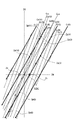
そうすると、動作点ZpがC1(6)とC2(12)との交点Zp(7) へ移動した直後の第7サイクルでは、第2の整合アルゴリズムの下で、次のような演算結果が得られる。なお、上記したように動作点Zp(7)の座標位置(ZMm,Zθm)は(1.5,4)である。
ΔC1=[1.5+2×4]=[9.5]>0⇒+1
Then, in the seventh cycle immediately after the operating point Z p moves to the intersection Z p (7) between C 1 (6) and C 2 (12), the following operation is performed under the second matching algorithm: Results are obtained. As described above, the coordinate position (ZM m , Zθ m ) of the operating point Z p (7) is (1.5, 4).
ΔC 1 = [1.5 + 2 × 4] = [9.5]> 0⇒ + 1
この演算結果にしたがって、ΔC1=+1の1ステップ可変制御が実行される。その結果、図10に示すように、C2座標軸はC2(12)から左上に1ピッチ隣のC2(13)へ移動し、動作点ZpはC1(6)とC2(13)との交点Zp(8)へ移動する。この移動先の動作点Zp(8)の座標位置(ZMm,Zθm)は(0.5,2)である。 According to this calculation result, one -step variable control of ΔC 1 = + 1 is executed. As a result, as shown in FIG. 10, the C 2 coordinate axis moves from C 2 (12) to C 2 (13) which is one pitch next to the upper left, and the operating point Z p is C 1 (6) and C 2 (13 ) To the intersection Z p (8). The coordinate position (ZM m , Zθ m ) of the movement destination operating point Z p (8) is (0.5, 2).
さらに、第8サイクルでは、次のような演算結果が得られる。
ΔC1=[0.5+2×2]=[4.5]>0⇒+1
Furthermore, the following calculation results are obtained in the eighth cycle.
ΔC 1 = [0.5 + 2 × 2] = [4.5]> 0⇒ + 1
この演算結果にしたがって、ΔC1=+1の1ステップ可変制御が実行される。その結果、図10に示すように、C2座標軸はC2(13)から左上に1ピッチ隣のC2(14)へ移動し、動作点ZpはC1(6)とC2(14)との交点Zp(9)へ移動する。この移動先の動作点Zp(9)の座標位置(ZMm,Zθm)は(−0.5,0)である。すなわち、原点O(整合点ZS)に非常に近い実現可能なベストの擬似的整合点ZBに辿り着いたことになる。 According to this calculation result, one -step variable control of ΔC 1 = + 1 is executed. As a result, as shown in FIG. 10, the C 2 coordinate axis moves from C 2 (13) to C 2 (14) which is one pitch on the upper left, and the operating point Z p is C 1 (6) and C 2 (14 ) To the intersection Z p (9). The coordinate position (ZM m , Zθ m ) of this movement destination operating point Z p (9) is (−0.5, 0). That is, the best pseudo matching point Z B that can be realized is very close to the origin O (matching point Z S ).
第2の整合アルゴリズムにおいても、演算式(3),(4)が非常に簡単であり、しかもテーブルを用いないため、演算処理ひいては動作点移動処理(ステップS9)を短時間で高速に行うことができる。 Also in the second matching algorithm, since the arithmetic expressions (3) and (4) are very simple and do not use a table, the arithmetic processing and the operation point moving processing (step S 9 ) are performed at high speed in a short time. be able to.
この実施形態において、コントローラ90は、上記のようにして動作点Zpが収束点ZBに辿り着くと、整合動作終了判定処理(ステップS2)により、そのことを検出し、動作点Zpが予め設定した内側近接範囲内に入ったものと判定して(ステップS3)、第2の整合アルゴリズム(第2のマッチング制御部)の動作を停止させて、動作点Zpを収束点ZBで落ち着かせる(ステップS3→S4)。こうして、今回のオートマッチング動作がいったん終了する。
In this embodiment, when the operating point Z p reaches the convergence point Z B as described above, the
コントローラ90は、その後も、インピーダンス測定部84より一定サイクル毎に負荷側インピーダンスZの絶対値測定値ZMmおよび位相測定値Zθmを取得して、整合点Zsに対する動作点Zpの相対的な位置関係または距離関係を継続的に監視し続ける。
After that, the
実際、チャンバ10内の圧力変動や何らかの外因等によってプラズマ負荷のインピーダンスが変化すると、動作点Zpに対してインピーダンス座標系そのものが相対的に動いて、オートマッチングが停止しているにも関わらずインピーダンス座標上で動作点Zpが一瞬にして整合点Zsから遠い位置へ移動し、整合が外れた状態になる。
In fact, if the impedance of the plasma load changes due to pressure fluctuations in the
コントローラ90は、そのような事態によって整合が外れたことを検出すると、オートマッチング動作を再開する(ステップS3→S5)。そして、上記と同様にして、第1の整合アルゴリズム(第1のマッチング制御部)および第2の整合アルゴリズム(第2のマッチング制御部)を順次働かせ、最終的には動作点Zpを所定の内側近接範囲内に収束させて、実質的な整合状態を短時間で確立することができる。
When the
図10の例では第2の整合アルゴリズムにおいてC1座標軸と直交する基準線TC1Sを移動目標にして演算式(3)を用いたが、所定の条件またはその時の状況に応じてC2座標軸と直交する基準線TC2Sを移動目標にして演算式(4)を用いることも可能である。 In the example of FIG. 10, the calculation formula (3) is used with the reference line TC 1S orthogonal to the C 1 coordinate axis as the movement target in the second matching algorithm, but the C 2 coordinate axis is determined according to a predetermined condition or the situation at that time. It is also possible to use the calculation formula (4) with the orthogonal reference line TC 2S as a movement target.
また、第2の整合アルゴリズムを終止させるための内側近接範囲は、オートマッチングの所要速度および精度や可変コンデンサ80,82のステップ幅、設定変化率等を勘案して任意に設定してよい。たとえば、C1座標軸あるいはC2座標軸のピッチ幅またはZM座標軸もしくはZθ座標軸上の間隔を基準値とし、その基準値に所定の係数を乗じた値の半径(または直径)を有し、原点O(整合点Zp)を中心とする円を内側近接範囲とすることも可能である。
Further, the inner proximity range for terminating the second matching algorithm may be arbitrarily set in consideration of the required speed and accuracy of auto-matching, the step widths of the
あるいは、第2の整合アルゴリズムの下で動作点Zpを移動させる際に、各移動先の座標位置(ZMm,Zθm)と原点O(整合点Zp)との離間距離を演算する。そうすると、動作点Zpがステップ移動する度毎にその離間距離は次第に短くなるが、どこかで離間距離が増大に転じるので、その1つ手前の座標位置を収束点に決めて、そこに動作点Zpを戻すようにしてもよい。この場合は、該収束点の座標位置をもって内側近接範囲内とみなすことができる。 Alternatively, when the operating point Z p is moved under the second matching algorithm, the separation distance between the coordinate position (ZM m , Zθ m ) of each movement destination and the origin O (matching point Z p ) is calculated. Then, every time the operating point Z p moves stepwise, the separation distance gradually decreases, but the separation distance starts to increase somewhere, so the coordinate position one before is determined as the convergence point, and the operation is performed there. it may be returned to the point Z p. In this case, the coordinate position of the convergence point can be regarded as being within the inner proximity range.
あるいは、第2の整合アルゴリズムの下で動作点Zpを移動させる際に、動作点Zpと基準線TC1S(TC2S)との距離間隔を演算し、基準線TC1S(TC2S)との距離間隔が極小になる動作点Zpの座標位置(ZMm,Zθm)を収束点とすることも可能である。 Alternatively, when the operating point Z p is moved under the second matching algorithm, the distance between the operating point Z p and the reference line TC 1S (TC 2S ) is calculated, and the reference line TC 1S (TC 2S ) and It is also possible to use the coordinate position (ZM m , Zθ m ) of the operating point Z p at which the distance interval is minimized as the convergence point.
同様に、第1の整合アルゴリズムを終止させるための外側近接範囲も、オートマッチングの所要速度および精度や可変コンデンサ80,82のステップ幅、設定変化率等を勘案して任意に設定してよい。本発明においては、第1の整合アルゴリズムと第2の整合アルゴリズムとを段階的に切り換えて使用することが最も重要であり、第1の整合アルゴリズムから第2の整合アルゴリズムへ切り換えるタイミングはさほど重要ではない。
Similarly, the outer proximity range for terminating the first matching algorithm may be arbitrarily set in consideration of the required speed and accuracy of auto matching, the step widths of the
上記の例(図7)においては、動作点Zpが上記循環ルート(Zp(7)→Zp(8) →Zp(9)→Zp(10)→Zp(11))上に入れば、その中の任意の動作点位置から第2の整合アルゴリズムの下で実質的な擬似的整合点ZA,ZBに辿り着くことができる。 In the above example (FIG. 7), the operating point Z p is above the circulation route (Z p (7) → Z p (8) → Z p (9) → Z p (10) → Z p (11)). Then, it is possible to reach the substantial pseudo matching points Z A and Z B under the second matching algorithm from any operating point position therein.
たとえば、図11に示すように、第1の整合アルゴリズムの下で動作点ZpがC1(5)とC2(13)との交点Zp(8)へ移動したところで、第2の整合アルゴリズムに切り換えると、直後の第8のサイクルでは、次のような演算結果が得られる。なお、上記したように動作点Zp(8)の座標位置(ZMm,Zθm)は(−1.5,−4)である。
ΔC1=[−1.5+2×(−4)]=[−9.5]<0⇒−1
For example, as shown in FIG. 11, when the operating point Z p moves to the intersection Z p (8) between C 1 (5) and C 2 (13) under the first matching algorithm, the second matching is performed. When switching to the algorithm, the following calculation result is obtained in the eighth cycle immediately after. As described above, the coordinate position (ZM m , Zθ m ) of the operating point Z p (8) is (−1.5, −4).
ΔC 1 = [− 1.5 + 2 × (−4)] = [− 9.5] <0⇒−1
この演算結果にしたがって、ΔC1=−1の1ステップ可変制御が実行される。その結果、図11に示すように、C2座標軸はC2(13)から右下に1ピッチ隣のC2(12)へ移動し、動作点ZpはC1(5)とC2(12)との交点Zp(9)へ移動する。この移動先の動作点Zp(9)の座標位置(ZMm,Zθm)は(−0.5,−2)である。 According to this calculation result, one -step variable control with ΔC 1 = −1 is executed. As a result, as shown in FIG. 11, the C 2 coordinate axis moves from C 2 (13) to C 2 (12) adjacent to one pitch in the lower right, and the operating point Z p is C 1 (5) and C 2 ( Move to intersection Z p (9) with 12). The coordinate position (ZM m , Zθ m ) of this movement destination operating point Z p (9) is (−0.5, −2).
さらに、直後の第9サイクルでは、次のような演算結果が得られる。
ΔC1=[−0.5+2×(−2)]=[−4.5]<0⇒−1
Further, in the ninth cycle immediately after, the following calculation result is obtained.
ΔC 1 = [− 0.5 + 2 × (−2)] = [− 4.5] <0⇒−1
この演算結果にしたがって、ΔC1=−1の1ステップ可変制御が実行される。その結果、図11に示すように、C2座標軸はC2(12)から右下に1ピッチ隣のC2(11)へ移動し、動作点ZpはC1(5)とC2(11)との交点Zp(10)へ移動する。この移動先の動作点Zp(10)の座標位置(ZMm,Zθm)は(0.5,0)であり、原点O(整合点ZS)に最も近い実現可能なベストの収束点ZBに辿りつく。 According to this calculation result, one -step variable control with ΔC 1 = −1 is executed. As a result, as shown in FIG. 11, the C 2 coordinate axis moves from C 2 (12) to C 2 (11), which is adjacent to one pitch to the lower right, and the operating point Z p becomes C 1 (5) and C 2 ( Move to intersection Z p (10) with 11). The coordinate position (ZM m , Zθ m ) of this movement point Z p (10) is (0.5, 0) and is the best feasible convergence point closest to the origin O (alignment point Z S ). Reach Z B.
動作点Zpが外側近接範囲内に入ったか否かの判定も、種種の判断基準を用いることができる。原点O(整合点ZS)と動作点Zpとの距離間隔に基づいてもよいが、基準線C1S(C2S)と動作点Zpとの位置関係または距離間隔に基づいて、動作点Zpが外側近接範囲内に入ったか否かを判定することも可能である。たとえば、上記の例(図7)においては、上記循環ルート上の外であっても、基準線C1Sに隣接するC1座標軸C1(5),C1(6)上に動作点Zpが乗ったところで、外側近接範囲内に入ったものとみなすことも可能である。その場合は、動作点ZpがZp(4),Zp(5)またはZp(6)に着いたところで、第1の整合アルゴリズムから第2の整合アルゴリズムに切り換えることができる。もしくは、C1座標軸とC2座標軸における1ステップ当たりの移動距離の差が既知の場合、図10および図11の手法で用いた手段のように、移動距離が小さい方のみ第2のアルゴリズムへの切り換えを行い、相対的に頻繁に移動させることで、外側近接範囲をラフに設定することができる。 Determining the operating point Z p is whether enters the outer proximity range can also be used criteria various. Although it may be based on the distance interval between the origin O (alignment point Z S ) and the operating point Z p , the operating point is determined based on the positional relationship or the distance interval between the reference line C 1S (C 2S ) and the operating point Z p. It is also possible to determine whether or not Z p is within the outer proximity range. For example, in the above example (FIG. 7), the operating point Z p is located on the C 1 coordinate axes C 1 (5) and C 1 (6) adjacent to the reference line C 1S even outside the circulation route. It is also possible to consider that the vehicle has entered the outside proximity range when it is on. In that case, when the operating point Z p reaches Z p (4), Z p (5) or Z p (6), the first matching algorithm can be switched to the second matching algorithm. Alternatively, when the difference in the movement distance per step between the C 1 coordinate axis and the C 2 coordinate axis is known, only the one with the smaller movement distance is applied to the second algorithm as in the method used in the method of FIGS. By switching and moving relatively frequently, the outer proximity range can be set roughly.
また、図示省略するが、第1および第2可変コンデンサ80,82の容量ポジョンC1,C2をコントローラ90にフィードバックする手段を備え、コントローラ90が容量ポジョンC1,C2に応じて第1および第2の傾きR1,R2、内側近接範囲、外側近接範囲を可変することも可能である。
Although not shown in the figure, there is provided means for feeding back the capacitance positions C 1 and C 2 of the first and second
上記実施形態におけるプラズマ処理装置は、主としてプラズマ生成用の第1の高周波と主としてイオン引き込み用の第2の高周波とをサセプタ12に印加するRF下部二周波印加型であった。しかし、別の実施形態として、図示省略するが、下部電極にプラズマ生成用の高周波を1つ印加するタイプの装置であってもよい。また、図示省略するが、プラズマ生成用の高周波を上部電極に印加するタイプの装置であってもよい。その場合、イオン引き込み用の高周波を下部電極に印加してもよい。
The plasma processing apparatus in the above embodiment is an RF lower two-frequency application type in which a first high frequency for plasma generation and a second high frequency for mainly ion attraction are applied to the
また、上記実施形態は、チャンバ内で平行平板電極間の高周波放電によってプラズマを生成する容量結合型プラズマ処理装置に係るものであった。しかし、本発明は、チャンバの上面または周囲にアンテナを配置して誘電磁界の下でプラズマを生成する誘導結合型プラズマ処理装置や、マイクロ波のパワーを用いてプラズマを生成するマイクロ波プラズマ処理装置等にも適用可能である。 Moreover, the said embodiment concerns the capacitive coupling type plasma processing apparatus which produces | generates a plasma by the high frequency discharge between parallel plate electrodes within a chamber. However, the present invention provides an inductively coupled plasma processing apparatus for generating plasma under a dielectric magnetic field by disposing an antenna on the upper surface or the periphery of a chamber, or a microwave plasma processing apparatus for generating plasma using microwave power. The present invention can also be applied.
本発明は、プラズマエッチング装置に限定されず、プラズマCVD、プラズマ酸化、プラズマ窒化、スパッタリングなどの他のプラズマ処理装置にも適用可能である。また、本発明における被処理基板は半導体ウエハに限るものではなく、フラットパネルディスプレイ用の各種基板や、フォトマスク、CD基板、プリント基板等も可能である。 The present invention is not limited to a plasma etching apparatus, but can be applied to other plasma processing apparatuses such as plasma CVD, plasma oxidation, plasma nitridation, and sputtering. Further, the substrate to be processed in the present invention is not limited to a semiconductor wafer, and various substrates for flat panel displays, photomasks, CD substrates, printed substrates, and the like are also possible.
10 チャンバ
12 サセプタ
32,70 高周波電源
34,72 整合器
62 処理ガス供給部
80 第1可変コンデンサ
82 第2可変コンデンサ
84 インピーダンス測定部
86 第1ステッピングモータ
88 第2ステッピングモータ
90 コントローラ
DESCRIPTION OF
Claims (12)
前記高周波電源に対して前記負荷と並列に接続される第1の可変コンデンサと、
前記第1の可変コンデンサの静電容量をステップ的に可変するための第1のステップ型容量可変機構と、
前記高周波電源に対して前記負荷と直列に接続される第2の可変コンデンサと、
前記第2の可変コンデンサの静電容量をステップ的に可変するための第2のステップ型容量可変機構と、
前記高周波電源の出力端子から見た負荷側のインピーダンスについてその絶対値および位相を測定するインピーダンス測定部と、
前記インピーダンス測定部より得られる前記負荷側インピーダンスの絶対値および位相の測定値に応じて、前記絶対値測定値および前記位相測定値をそれぞれ所定の絶対値基準値および位相基準値に可及的に近づけるように、前記第1および第2のステップ型容量可変機構を介して前記第1および第2の可変コンデンサの静電容量を可変制御するコントローラと
を具備し、
前記コントローラが、
前記負荷側インピーダンスの絶対値および位相を互いに直交する2つの座標軸とするインピーダンス座標上で、前記第1の可変コンデンサの静電容量に対する前記負荷側インピーダンスの絶対値および位相の設定変化率に対応した第1の傾きを有し、かつ前記絶対値基準値および前記位相基準値の座標位置で表わされる整合点を通る第1の基準線を目標にして、または前記第2の可変コンデンサの静電容量に対する前記負荷側インピーダンスの絶対値および位相の設定変化率に対応した第2の傾きを有し、かつ前記整合点を通る第2の基準線を目標にして、前記絶対値測定値および前記位相測定値の座標位置で表わされる動作点を前記整合点に対して第1の近接範囲内に近づけるように、前記第1および第2の可変コンデンサの少なくとも一方の静電容量を可変制御する第1のマッチング制御部と、
前記インピーダンス座標上で、前記動作点が前記第1の近接範囲内に入った後に、前記第1または第2の基準線と直交し、かつ前記整合点を通る第3の基準線を目標として、前記動作点を前記整合点に対して第2の近接範囲内に近づけるように、前記第1または第2の可変コンデンサの少なくとも一方の静電容量を可変制御する第2のマッチング制御部と
を有する自動整合装置。 An automatic matching device that automatically matches impedance between a high frequency power source that outputs a high frequency of a constant frequency and a load that receives the supply of the high frequency,
A first variable capacitor connected in parallel with the load to the high-frequency power source;
A first step-type capacitance variable mechanism for stepwise varying the capacitance of the first variable capacitor;
A second variable capacitor connected in series with the load with respect to the high-frequency power source;
A second step-type capacitance variable mechanism for stepwise varying the capacitance of the second variable capacitor;
An impedance measurement unit that measures the absolute value and phase of the load-side impedance viewed from the output terminal of the high-frequency power source;
According to the absolute value and phase measurement value of the load side impedance obtained from the impedance measurement unit, the absolute value measurement value and the phase measurement value are made as large as possible to a predetermined absolute value reference value and phase reference value, respectively. A controller for variably controlling the capacitances of the first and second variable capacitors via the first and second step-type capacitance variable mechanisms so as to approach each other,
The controller is
Corresponding to the absolute value of the load side impedance and the set change rate of the phase with respect to the capacitance of the first variable capacitor on the impedance coordinate having the absolute value and phase of the load side impedance as two coordinate axes orthogonal to each other A first reference line having a first slope and passing through a matching point represented by a coordinate position of the absolute value reference value and the phase reference value, or the capacitance of the second variable capacitor The absolute value measured value and the phase measured with a second reference line having a second slope corresponding to a set change rate of the absolute value and phase of the load side impedance with respect to the reference point and passing through the matching point At least one of the first and second variable capacitors so that the operating point represented by the coordinate position of the value is brought closer to the matching point within a first proximity range. The electrostatic capacitance of the first matching control unit for variably controlling,
On the impedance coordinate, after the operating point enters the first proximity range, a target is a third reference line orthogonal to the first or second reference line and passing through the matching point. A second matching control unit that variably controls the electrostatic capacity of at least one of the first and second variable capacitors so that the operating point is brought closer to the matching point within a second proximity range. Automatic alignment device.
前記高周波電源に対して前記負荷と並列に接続される第1の可変コンデンサと、
前記第1の可変コンデンサの静電容量をステップ的に可変するための第1のステップ型容量可変機構と、
前記高周波電源に対して前記負荷と直列に接続される第2の可変コンデンサと、
前記第2の可変コンデンサの静電容量をステップ的に可変するための第2のステップ型容量可変機構と、
前記高周波電源の出力端子から見た負荷側のインピーダンスについてその絶対値および位相を測定するインピーダンス測定部と、
前記インピーダンス測定部より得られる前記負荷側インピーダンスの絶対値および位相の測定値に応じて、前記絶対値測定値および前記位相測定値をそれぞれ所定の絶対値基準値および位相基準値に可及的に近づけるように、前記第1および第2のステップ型容量可変機構を介して前記第1および第2の可変コンデンサの静電容量を可変制御するコントローラと
を具備し、
前記コントローラが、
前記負荷側インピーダンスの絶対値および位相を互いに直交する2つの座標軸とするインピーダンス座標上で、前記第1の可変コンデンサの静電容量に対する前記負荷側インピーダンスの絶対値および位相の設定変化率に対応した第1の傾きを有し、かつ前記絶対値基準値および前記位相基準値の座標位置で表わされる整合点を通る第1の基準線を目標として、または前記第2の可変コンデンサの静電容量に対する前記負荷側インピーダンスの絶対値および位相の設定変化率に対応した第2の傾きを有し、かつ前記整合点を通る第2の基準線を目標として、前記絶対値測定値および前記位相測定値の座標位置で表わされる動作点を前記第1または第2の基準線に対して可及的に近づけるように、前記第1および第2の可変コンデンサの少なくとも一方の静電容量を可変制御する第1のマッチング制御部と、
前記インピーダンス座標上で、前記動作点が前記第1または第2の基準線に対して可及的に近づいた後に、前記第1または第2の基準線と直交し、かつ前記整合点を通る第3の基準線を目標として、前記動作点を前記第3の基準線に可及的に近づけるように、前記第1または第2の可変コンデンサの少なくとも一方の静電容量を可変制御する第2のマッチング制御部と
を有する自動整合装置。 An automatic matching device that automatically matches impedance between a high frequency power source that outputs a high frequency of a constant frequency and a load that receives the supply of the high frequency,
A first variable capacitor connected in parallel with the load to the high-frequency power source;
A first step-type capacitance variable mechanism for stepwise varying the capacitance of the first variable capacitor;
A second variable capacitor connected in series with the load with respect to the high-frequency power source;
A second step-type capacitance variable mechanism for stepwise varying the capacitance of the second variable capacitor;
An impedance measurement unit that measures the absolute value and phase of the load-side impedance viewed from the output terminal of the high-frequency power source;
According to the absolute value and phase measurement value of the load side impedance obtained from the impedance measurement unit, the absolute value measurement value and the phase measurement value are made as large as possible to a predetermined absolute value reference value and phase reference value, respectively. A controller for variably controlling the capacitances of the first and second variable capacitors via the first and second step-type capacitance variable mechanisms so as to approach each other,
The controller is
Corresponding to the absolute value of the load side impedance and the set change rate of the phase with respect to the capacitance of the first variable capacitor on the impedance coordinate having the absolute value and phase of the load side impedance as two coordinate axes orthogonal to each other A first reference line having a first slope and passing through a matching point represented by the coordinate position of the absolute value reference value and the phase reference value is set as a target, or with respect to the capacitance of the second variable capacitor The absolute value of the load side impedance and the phase measurement value of the phase measurement value having a second slope corresponding to the set change rate of the phase and the second reference line passing through the matching point as a target. The number of the first and second variable capacitors is reduced so that the operating point represented by the coordinate position is as close as possible to the first or second reference line. Also a first matching control unit for variably controlling one of the capacitance,
On the impedance coordinate, after the operating point approaches the first or second reference line as much as possible, the operating point is orthogonal to the first or second reference line and passes through the matching point. A second reference line variably controlling at least one of the capacitances of the first or second variable capacitor so as to bring the operating point as close as possible to the third reference line with a reference line of 3 as a target. An automatic alignment apparatus having a matching control unit.
前記処理容器内に所望の処理ガスを供給する処理ガス供給部と、
前記処理容器内で高周波放電により前記処理ガスのプラズマを生成するプラズマ生成部と、
前記高周波放電に用いられる一定周波数の高周波を出力する高周波電源と、
前記高周波電源と前記プラズマ生成部との間に接続される請求項1〜10のいずれか一項に記載の自動整合装置と
を有するプラズマ処理装置。 A processing container capable of being evacuated to accommodate a substrate to be processed in a removable manner; and
A processing gas supply unit for supplying a desired processing gas into the processing container;
A plasma generating section for generating plasma of the processing gas by high-frequency discharge in the processing vessel;
A high-frequency power source that outputs a high-frequency wave having a constant frequency used for the high-frequency discharge;
The plasma processing apparatus which has an automatic alignment apparatus as described in any one of Claims 1-10 connected between the said high frequency power supply and the said plasma production | generation part.
前記処理容器内に所望の処理ガスを供給する処理ガス供給部と、
前記処理容器内で前記処理ガスのプラズマを生成するプラズマ生成部と、
前記処理容器内で前記基板を載置して保持する電極と、
前記プラズマから前記電極上の前記基板に入射するイオンのエネルギーを制御するのに用いられる一定周波数の高周波を出力する高周波電源と、
前記高周波電源と前記電極との間に接続される請求項1〜10のいずれか一項に記載の自動整合装置と
を有するプラズマ処理装置。 A processing container capable of being evacuated to accommodate a substrate to be processed in a removable manner; and
A processing gas supply unit for supplying a desired processing gas into the processing container;
A plasma generating section for generating plasma of the processing gas in the processing container;
An electrode for mounting and holding the substrate in the processing container;
A high frequency power source that outputs a high frequency of a constant frequency used to control the energy of ions incident on the substrate on the electrode from the plasma;
The plasma processing apparatus which has an automatic alignment apparatus as described in any one of Claims 1-10 connected between the said high frequency power supply and the said electrode.
Priority Applications (5)
| Application Number | Priority Date | Filing Date | Title |
|---|---|---|---|
| JP2010042049A JP5582823B2 (en) | 2010-02-26 | 2010-02-26 | Automatic alignment apparatus and plasma processing apparatus |
| KR1020110016216A KR101790789B1 (en) | 2010-02-26 | 2011-02-23 | Automatic matching unit and plasma processing apparatus |
| US13/034,331 US9384945B2 (en) | 2010-02-26 | 2011-02-24 | Automatic matching unit and plasma processing apparatus |
| CN2011100486054A CN102169789B (en) | 2010-02-26 | 2011-02-25 | Automatic matching unit and plasma processing apparatus |
| TW100106398A TWI493591B (en) | 2010-02-26 | 2011-02-25 | Automatic integration device and plasma processing device |
Applications Claiming Priority (1)
| Application Number | Priority Date | Filing Date | Title |
|---|---|---|---|
| JP2010042049A JP5582823B2 (en) | 2010-02-26 | 2010-02-26 | Automatic alignment apparatus and plasma processing apparatus |
Publications (2)
| Publication Number | Publication Date |
|---|---|
| JP2011182046A JP2011182046A (en) | 2011-09-15 |
| JP5582823B2 true JP5582823B2 (en) | 2014-09-03 |
Family
ID=44490909
Family Applications (1)
| Application Number | Title | Priority Date | Filing Date |
|---|---|---|---|
| JP2010042049A Active JP5582823B2 (en) | 2010-02-26 | 2010-02-26 | Automatic alignment apparatus and plasma processing apparatus |
Country Status (5)
| Country | Link |
|---|---|
| US (1) | US9384945B2 (en) |
| JP (1) | JP5582823B2 (en) |
| KR (1) | KR101790789B1 (en) |
| CN (1) | CN102169789B (en) |
| TW (1) | TWI493591B (en) |
Families Citing this family (11)
| Publication number | Priority date | Publication date | Assignee | Title |
|---|---|---|---|---|
| JP5867701B2 (en) | 2011-12-15 | 2016-02-24 | 東京エレクトロン株式会社 | Plasma processing equipment |
| KR20130086825A (en) * | 2012-01-26 | 2013-08-05 | 세메스 주식회사 | Adjustable capacitor, impedance matching device and substrate treating apparatus |
| KR20140059422A (en) * | 2012-11-08 | 2014-05-16 | 엘아이지에이디피 주식회사 | Inductively coupled plasma processing apparatus and control method thereof |
| CN103943449B (en) * | 2013-06-28 | 2016-08-17 | 厦门天马微电子有限公司 | The measuring method of a kind of radio frequency cross talk, equipment and system |
| CN104377106B (en) * | 2013-08-16 | 2016-12-28 | 中微半导体设备(上海)有限公司 | Plasma reaction chamber impedance auto-match method |
| JP6586394B2 (en) * | 2016-03-28 | 2019-10-02 | 東京エレクトロン株式会社 | How to get data representing capacitance |
| US10109460B2 (en) * | 2016-11-30 | 2018-10-23 | Lam Research Corporation | Universal non-invasive chamber impedance measurement system and associated methods |
| JP6676020B2 (en) * | 2017-09-20 | 2020-04-08 | 株式会社日立ハイテク | Plasma processing apparatus and plasma processing apparatus state prediction method |
| US10910197B2 (en) * | 2018-10-19 | 2021-02-02 | Mks Instruments, Inc. | Impedance matching network model based correction scheme and performance repeatability |
| JP7257918B2 (en) * | 2019-08-29 | 2023-04-14 | 東京エレクトロン株式会社 | Plasma processing system and plasma ignition support method |
| CN111968905B (en) * | 2020-08-03 | 2023-11-14 | 北京北方华创微电子装备有限公司 | Radio frequency starting control method and device for semiconductor equipment |
Family Cites Families (22)
| Publication number | Priority date | Publication date | Assignee | Title |
|---|---|---|---|---|
| JPS5973900A (en) * | 1982-10-18 | 1984-04-26 | 株式会社日立国際電気 | Impedance automatic matching device for plasma generator |
| US5195045A (en) * | 1991-02-27 | 1993-03-16 | Astec America, Inc. | Automatic impedance matching apparatus and method |
| JPH09134798A (en) * | 1995-11-08 | 1997-05-20 | Jeol Ltd | High frequency device |
| US5689215A (en) * | 1996-05-23 | 1997-11-18 | Lam Research Corporation | Method of and apparatus for controlling reactive impedances of a matching network connected between an RF source and an RF plasma processor |
| US5889252A (en) * | 1996-12-19 | 1999-03-30 | Lam Research Corporation | Method of and apparatus for independently controlling electric parameters of an impedance matching network |
| JPH10209789A (en) | 1997-01-28 | 1998-08-07 | Jeol Ltd | Matching method of high-frequency device |
| US5842154A (en) * | 1997-09-15 | 1998-11-24 | Eni Technologies, Inc. | Fuzzy logic tuning of RF matching network |
| US5929717A (en) * | 1998-01-09 | 1999-07-27 | Lam Research Corporation | Method of and apparatus for minimizing plasma instability in an RF processor |
| JP4286404B2 (en) * | 1999-10-15 | 2009-07-01 | 東京エレクトロン株式会社 | Matching device and plasma processing apparatus |
| US7030335B2 (en) * | 2000-03-17 | 2006-04-18 | Applied Materials, Inc. | Plasma reactor with overhead RF electrode tuned to the plasma with arcing suppression |
| TW529085B (en) * | 2000-09-22 | 2003-04-21 | Alps Electric Co Ltd | Method for evaluating performance of plasma treatment apparatus or performance confirming system of plasma treatment system |
| TW200300649A (en) * | 2001-11-27 | 2003-06-01 | Alps Electric Co Ltd | Plasma processing apparatus, its driving method, matching circuit design system, and plasma processing method |
| JP4071044B2 (en) * | 2002-02-08 | 2008-04-02 | 株式会社ダイヘン | Impedance matching device output end characteristic analysis method, impedance matching device, and impedance matching device output end characteristic analysis system |
| JP4439169B2 (en) * | 2002-09-10 | 2010-03-24 | 株式会社アルバック | Vacuum processing method and vacuum apparatus |
| US6876155B2 (en) * | 2002-12-31 | 2005-04-05 | Lam Research Corporation | Plasma processor apparatus and method, and antenna |
| JP3768999B2 (en) * | 2003-10-29 | 2006-04-19 | 澄英 池之内 | Plasma processing apparatus and control method thereof |
| JP4203406B2 (en) * | 2003-12-04 | 2009-01-07 | 株式会社ニッシン | Microwave circuit tuning method and microwave circuit automatic tuning apparatus |
| US7794615B2 (en) | 2005-03-31 | 2010-09-14 | Tokyo Electron Limited | Plasma processing method and apparatus, and autorunning program for variable matching unit |
| JP5213150B2 (en) * | 2005-08-12 | 2013-06-19 | 国立大学法人東北大学 | Plasma processing apparatus and product manufacturing method using plasma processing apparatus |
| JP5210659B2 (en) * | 2008-02-28 | 2013-06-12 | 株式会社日立ハイテクノロジーズ | Plasma processing equipment |
| JP5264231B2 (en) * | 2008-03-21 | 2013-08-14 | 東京エレクトロン株式会社 | Plasma processing equipment |
| JP2010045664A (en) * | 2008-08-14 | 2010-02-25 | Tokyo Electron Ltd | Matching device, matching method, plasma treatment device, and storage medium |
-
2010
- 2010-02-26 JP JP2010042049A patent/JP5582823B2/en active Active
-
2011
- 2011-02-23 KR KR1020110016216A patent/KR101790789B1/en active IP Right Grant
- 2011-02-24 US US13/034,331 patent/US9384945B2/en active Active
- 2011-02-25 CN CN2011100486054A patent/CN102169789B/en active Active
- 2011-02-25 TW TW100106398A patent/TWI493591B/en active
Also Published As
| Publication number | Publication date |
|---|---|
| KR20110098653A (en) | 2011-09-01 |
| CN102169789A (en) | 2011-08-31 |
| KR101790789B1 (en) | 2017-10-26 |
| TWI493591B (en) | 2015-07-21 |
| US20110209827A1 (en) | 2011-09-01 |
| CN102169789B (en) | 2013-11-06 |
| JP2011182046A (en) | 2011-09-15 |
| US9384945B2 (en) | 2016-07-05 |
| TW201201244A (en) | 2012-01-01 |
Similar Documents
| Publication | Publication Date | Title |
|---|---|---|
| JP5582823B2 (en) | Automatic alignment apparatus and plasma processing apparatus | |
| JP5632626B2 (en) | Automatic alignment apparatus and plasma processing apparatus | |
| US11447868B2 (en) | Method for controlling a plasma process | |
| US10250217B2 (en) | Method for impedance matching of plasma processing apparatus | |
| JP6843485B2 (en) | Multi-electrode board support assembly and phase control system | |
| US8608903B2 (en) | Plasma processing apparatus and plasma processing method | |
| KR102033120B1 (en) | Plasma-treatment method | |
| KR102021570B1 (en) | Plasma processing apparatus and heater temperature control method | |
| TWI595808B (en) | Plasma processing apparatus and plasma processing method | |
| CN109994355A (en) | A kind of plasma reactor with low frequency RF power profile adjustment function | |
| JP2000299198A (en) | Plasma processing device | |
| US11562887B2 (en) | Plasma processing apparatus and etching method | |
| US20040050327A1 (en) | Vertically translatable chuck assembly and method for a plasma reactor system | |
| US11037761B2 (en) | Control method and plasma processing apparatus | |
| JP2010045664A (en) | Matching device, matching method, plasma treatment device, and storage medium | |
| KR20190125178A (en) | Plasma processing apparatus and power supply control method | |
| CN107017178B (en) | Cycle averaged frequency tuning for low power voltage mode operation | |
| US20170347441A1 (en) | Dynamic control band for rf plasma current ratio control | |
| US11908665B2 (en) | Plasma processing apparatus and measurement method | |
| US11062881B2 (en) | Plasma etching method and plasma processing device | |
| US20100319621A1 (en) | Plasma processing apparatus and plasma processing method | |
| JP5914037B2 (en) | COOLING SYSTEM, SUBSTRATE PROCESSING APPARATUS HAVING COOLING SYSTEM, AND COOLING METHOD | |
| KR20190091209A (en) | Method for applying dc voltage and plasma processing apparatus |
Legal Events
| Date | Code | Title | Description |
|---|---|---|---|
| A621 | Written request for application examination |
Free format text: JAPANESE INTERMEDIATE CODE: A621 Effective date: 20130219 |
|
| A131 | Notification of reasons for refusal |
Free format text: JAPANESE INTERMEDIATE CODE: A131 Effective date: 20140311 |
|
| A521 | Request for written amendment filed |
Free format text: JAPANESE INTERMEDIATE CODE: A523 Effective date: 20140417 |
|
| TRDD | Decision of grant or rejection written | ||
| A01 | Written decision to grant a patent or to grant a registration (utility model) |
Free format text: JAPANESE INTERMEDIATE CODE: A01 Effective date: 20140708 |
|
| A61 | First payment of annual fees (during grant procedure) |
Free format text: JAPANESE INTERMEDIATE CODE: A61 Effective date: 20140715 |
|
| R150 | Certificate of patent or registration of utility model |
Ref document number: 5582823 Country of ref document: JP Free format text: JAPANESE INTERMEDIATE CODE: R150 |
|
| R250 | Receipt of annual fees |
Free format text: JAPANESE INTERMEDIATE CODE: R250 |
|
| R250 | Receipt of annual fees |
Free format text: JAPANESE INTERMEDIATE CODE: R250 |
|
| R250 | Receipt of annual fees |
Free format text: JAPANESE INTERMEDIATE CODE: R250 |
|
| R250 | Receipt of annual fees |
Free format text: JAPANESE INTERMEDIATE CODE: R250 |
|
| R250 | Receipt of annual fees |
Free format text: JAPANESE INTERMEDIATE CODE: R250 |