JP5582410B2 - Fixing apparatus and image forming apparatus - Google Patents
Fixing apparatus and image forming apparatus Download PDFInfo
- Publication number
- JP5582410B2 JP5582410B2 JP2011003396A JP2011003396A JP5582410B2 JP 5582410 B2 JP5582410 B2 JP 5582410B2 JP 2011003396 A JP2011003396 A JP 2011003396A JP 2011003396 A JP2011003396 A JP 2011003396A JP 5582410 B2 JP5582410 B2 JP 5582410B2
- Authority
- JP
- Japan
- Prior art keywords
- heating member
- fixing
- fixing device
- fixing belt
- heating
- Prior art date
- Legal status (The legal status is an assumption and is not a legal conclusion. Google has not performed a legal analysis and makes no representation as to the accuracy of the status listed.)
- Expired - Fee Related
Links
Images


Classifications
-
- G—PHYSICS
- G03—PHOTOGRAPHY; CINEMATOGRAPHY; ANALOGOUS TECHNIQUES USING WAVES OTHER THAN OPTICAL WAVES; ELECTROGRAPHY; HOLOGRAPHY
- G03G—ELECTROGRAPHY; ELECTROPHOTOGRAPHY; MAGNETOGRAPHY
- G03G15/00—Apparatus for electrographic processes using a charge pattern
- G03G15/20—Apparatus for electrographic processes using a charge pattern for fixing, e.g. by using heat
- G03G15/2003—Apparatus for electrographic processes using a charge pattern for fixing, e.g. by using heat using heat
- G03G15/2014—Apparatus for electrographic processes using a charge pattern for fixing, e.g. by using heat using heat using contact heat
- G03G15/2064—Apparatus for electrographic processes using a charge pattern for fixing, e.g. by using heat using heat using contact heat combined with pressure
-
- G—PHYSICS
- G03—PHOTOGRAPHY; CINEMATOGRAPHY; ANALOGOUS TECHNIQUES USING WAVES OTHER THAN OPTICAL WAVES; ELECTROGRAPHY; HOLOGRAPHY
- G03G—ELECTROGRAPHY; ELECTROPHOTOGRAPHY; MAGNETOGRAPHY
- G03G2215/00—Apparatus for electrophotographic processes
- G03G2215/20—Details of the fixing device or porcess
- G03G2215/2003—Structural features of the fixing device
- G03G2215/2016—Heating belt
- G03G2215/2035—Heating belt the fixing nip having a stationary belt support member opposing a pressure member
Description
本発明は、プリンタ、ファクシミリ、複写機などの画像形成装置に設けられる定着装置、及び、その定着装置を備えた画像形成装置に関するものである。 The present invention relates to a fixing device provided in an image forming apparatus such as a printer, a facsimile machine, and a copying machine, and an image forming apparatus including the fixing device.
従来、画像形成装置においては、像担持体上の潜像が現像装置から供給されたトナーによって現像され、像担持体上に顕像としてのトナー像が形成される。この像担持体上のトナー像は転写装置によって記録材に転写され、定着装置によって記録材上に定着される。 Conventionally, in an image forming apparatus, a latent image on an image carrier is developed with toner supplied from a developing device, and a toner image as a visible image is formed on the image carrier. The toner image on the image carrier is transferred to a recording material by a transfer device and fixed on the recording material by a fixing device.
特許文献1に記載の定着装置では、回転可能に設けられた駆動回転体である加圧ローラと、加圧ローラに対向して設けられた可撓性を有する無端状のベルト部材である定着ベルトとを、付勢バネからの付勢力で加圧ローラを定着ベルトに向かって付勢して圧接させることによりニップ部が形成される。また、定着ベルトの内周面側には、定着ベルトの内周面に接触しており定着ベルトを介して加圧ローラからの加圧を受ける加圧受け部材と、熱源であるヒータと、定着ベルトの内周面に対向して設けられヒータから熱を受けて定着ベルトを加熱するパイプ状の加熱部材とが設けられている。そして、ヒータから熱を受けた加熱部材により定着ベルトを加熱することで、定着ベルトを周方向にわたって全体的に加熱することができる。
In the fixing device described in
この定着装置では、定着ベルトの温度を所定の温度まで昇温させる立ち上げ動作で、ヒータから熱を受けた加熱部材により定着ベルトを熱しながら、駆動装置により加圧ローラを回転駆動させ、その加圧ローラの回転に従動させて定着ベルトを回転させる。そして、定着ベルトが所定の温度に達し立ち上げ動作が完了した後に、トナー像の付着した記録紙を定着ニップに挟み込んで搬送することにより、熱や圧力によって記録材上のトナー像が記録材に定着される。 In this fixing device, in a start-up operation for raising the temperature of the fixing belt to a predetermined temperature, the fixing roller is heated by a heating member that receives heat from the heater, and the pressure roller is rotationally driven by a driving device. The fixing belt is rotated by the rotation of the pressure roller. After the fixing belt reaches a predetermined temperature and the start-up operation is completed, the recording paper on which the toner image is adhered is sandwiched in the fixing nip and conveyed, so that the toner image on the recording material is applied to the recording material by heat or pressure. It is fixed.
加熱部材は板金に一端部と他端部とが対向するような曲げ加工を施してパイプ状に形成されている。加熱部材は、ニップ部を除く位置でベルト部材の内周面に対向するように形成され、ニップ部の位置には内側に向かって凹状に形成されるとともに加圧受け部材を配置するための開口が形成された凹部が設けられている。 The heating member is formed in a pipe shape by bending the sheet metal so that one end and the other end face each other. The heating member is formed so as to face the inner peripheral surface of the belt member at a position excluding the nip portion. The heating member is formed in a concave shape toward the inside at the position of the nip portion, and an opening for disposing the pressure receiving member. A recess in which is formed is provided.
ここで、パイプ状に形成されたステンレス鋼板のスプリングバックによって加熱部材の一端部と他端部とが離れていくように開いてしまうと、加熱部材と定着ベルトとが強く摺擦し合い定着ベルトの摩耗が加速してしまう。 Here, if the one end and the other end of the heating member are opened apart by the spring back of the stainless steel plate formed in a pipe shape, the heating member and the fixing belt rub against each other strongly and the fixing belt Wear will accelerate.
特許文献1に記載の定着装置では、二つのステーで加熱部材の一端部と他端部とを外周面側と内周面側とから挟み込んで連結し開かないように固定している。
In the fixing device described in
しかしながら、二つのステーで加熱部材の一端部と他端部とを挟み込んで連結する構成では、加熱部材の一端部と他端部とを連結するため専用のステーを設ける分、部品点数や組立工数が増え低コスト化を図るのが困難になるといった問題が生じる。 However, in the configuration in which one end and the other end of the heating member are sandwiched and connected by two stays, a dedicated stay is provided to connect the one end and the other end of the heating member. As a result, there is a problem that it becomes difficult to reduce costs.
本発明は以上の問題点に鑑みなされたものであり、その目的は、低コスト化を図りつつ、加熱部材と定着ベルトとが強く摺擦し合うのを抑制できる定着装置、及び、その定着装置を備えた画像形成装置を提供することである。 SUMMARY OF THE INVENTION The present invention has been made in view of the above problems, and an object of the present invention is to provide a fixing device capable of suppressing the friction between the heating member and the fixing belt while reducing the cost, and the fixing device. Is provided.
上記目的を達成するために、請求項1の発明は、回転可能に支持された駆動回転体と、前記駆動回転体を回転駆動させる駆動手段と、前記駆動回転体に対向して回転可能に設けられ可撓性を有する無端状のベルト部材と、前記駆動回転体を前記ベルト部材に向かって付勢して該駆動回転体を該ベルト部材に圧接させる付勢手段と、前記ベルト部材を介して前記駆動回転体からの加圧を受ける加圧受け部材と、前記ベルト部材の内周面側に設けられた熱源と、前記ベルト部材の内周面側に設けられ、板金を一端部と他端部とが対向するように曲げて管状に形成し前記駆動回転体と対向する位置に前記加圧受け部材が配置される開口が設けられた、前記熱源からの熱を受けて前記ベルト部材を加熱する加熱部材とを備えた定着装置において、前記加圧受け部材に設けられた係合部と、前記加熱部材の一端部及び他端部に設けられた被係合部とを係合させて、前記加圧受け部材により前記一端部と前記他端部とを連結したことを特徴とするものである。
また、請求項2の発明は、請求項1の定着装置において、上記加圧受け部材に設けられた上記係合部は突起形状であり、上記加熱部材の一端部及び他端部に設けられた上記被係合部は孔形状であり、前記係合部が前記被係合部の内周面に接して該係合部と該被係合部とが係合することを特徴とするものである。
また、請求項3の発明は、請求項1または2の定着装置において、上記加圧受け部材及び上記加熱部材は、上記係合部と上記被係合以外では接しないことを特徴とするものである。
また、請求項4の発明は、請求項1、2または3の定着装置において、上記加圧受け部材に設けられた上記係合部と、上記加熱部材に設けられた上記被係合部とを、長手方向に複数設けたことを特徴とするものである。
また、請求項5の発明は、請求項1、2、3または4の定着装置において、上記加圧受け部材は耐熱性の樹脂で形成されていることを特徴とするものである。
また、請求項6の発明は、請求項1、2、3、4または5の定着装置において、上記加熱部材は金属製であり肉厚が0.2[mm]以下であることを特徴とするものである。
また、請求項7の発明は、請求項1、2、3、4、5または6の定着装置において、上記加熱部材のビッカース硬さがHv280以下であることを特徴とするものである。
また、請求項8の発明は、請求項1、2、3、4、5、6または7の定着装置において、上記加熱部材がフェライト系ステンレス鋼からなることを特徴とするものである。
また、請求項9の発明は、請求項1、2、3、4、5、6、7または8の定着装置において、上記加熱部材の内周側に設けられ上記加圧受け部材に当接して該加圧受け部材を補強する補強部材を有しており、前記加圧受け部材を前記補強部材に長手方向で、装置で使用可能な記録媒体の最大幅以上の長さ全面で当接していることを特徴とするものである。
また、請求項10の発明は、記録媒体に対して画像を形成する画像形成部と、前記画像形成部で形成された前記記録媒体上の画像を定着させる定着手段とを備えた画像形成装置において、前記定着手段として、請求項1、2、3、4、5、6、7、8または9の定着装置を用いたことを特徴とするものである。
In order to achieve the above-mentioned object, the invention of
According to a second aspect of the present invention, in the fixing device of the first aspect, the engaging portion provided on the pressure receiving member has a protruding shape, and is provided at one end and the other end of the heating member. The engaged portion has a hole shape, and the engaging portion is in contact with an inner peripheral surface of the engaged portion, and the engaging portion and the engaged portion are engaged with each other. is there.
According to a third aspect of the present invention, in the fixing device of the first or second aspect, the pressure receiving member and the heating member do not contact the engaging portion except for the engaged portion. is there.
According to a fourth aspect of the present invention, in the fixing device of the first, second, or third aspect, the engaging portion provided in the pressure receiving member and the engaged portion provided in the heating member are provided. A plurality of them are provided in the longitudinal direction.
According to a fifth aspect of the present invention, in the fixing device of the first, second, third, or fourth aspect, the pressure receiving member is formed of a heat resistant resin.
According to a sixth aspect of the present invention, in the fixing device of the first, second, third, fourth or fifth aspect, the heating member is made of metal and has a thickness of 0.2 [mm] or less. Is.
According to a seventh aspect of the present invention, in the fixing device of the first, second, third, fourth, fifth or sixth aspect, the heating member has a Vickers hardness of Hv280 or less.
According to an eighth aspect of the present invention, in the fixing device of the first, second, third, fourth, fifth, sixth or seventh aspect, the heating member is made of ferritic stainless steel.
According to a ninth aspect of the present invention, there is provided the fixing device according to the first, second, third, fourth, fifth, sixth, seventh or eighth aspect, wherein the fixing device is provided on an inner peripheral side of the heating member and is in contact with the pressure receiving member. The pressure receiving member has a reinforcing member that reinforces the pressure receiving member, and the pressure receiving member is in contact with the reinforcing member in the longitudinal direction over the entire length longer than the maximum width of the recording medium usable in the apparatus. It is characterized by this.
According to a tenth aspect of the present invention, there is provided an image forming apparatus comprising: an image forming unit that forms an image on a recording medium; and a fixing unit that fixes an image on the recording medium formed by the image forming unit. A fixing device according to
本発明においては、加圧受け部材に設けられた係合部と、加熱部材の一端部及び他端部に設けられた被係合部とを係合させて、加圧受け部材により前記一端部と前記他端部とを連結するので、加熱部材の一端部と他端部とが離れていくように開くのを抑制できる。これにより、加熱部材とベルト部材とが強く摺擦し合うのを抑制することができる。また、前記一端部と前記他端部とを連結するため専用の部材を別途設ける場合よりも、部品点数や組立工数を低減させることができる。よって、その分、低コスト化を図ることができる。 In the present invention, the engagement portion provided in the pressure receiving member is engaged with the engaged portions provided in the one end portion and the other end portion of the heating member, and the one end portion is formed by the pressure receiving member. And the other end are connected, so that it is possible to suppress the opening of the heating member so that the one end and the other end are separated from each other. Thereby, it can suppress that a heating member and a belt member rub against each other strongly. Further, the number of parts and the number of assembling steps can be reduced as compared with the case where a dedicated member is separately provided to connect the one end and the other end. Therefore, the cost can be reduced accordingly.
以上、本発明によれば、低コスト化を図りつつ、加熱部材とベルト部材とが強く摺擦し合うのを抑制できるという優れた効果がある。 As mentioned above, according to this invention, there exists an outstanding effect that it can suppress that a heating member and a belt member rub against each other strongly, achieving cost reduction.
以下、この発明を実施するための最良の形態について、図を参照して詳細に説明する。なお、各図中、同一又は相当する部分には同一の符号を付しており、その重複説明は適宜に簡略化ないし省略する。 Hereinafter, the best mode for carrying out the present invention will be described in detail with reference to the drawings. In addition, in each figure, the same code | symbol is attached | subjected to the part which is the same or it corresponds, The duplication description is simplified or abbreviate | omitted suitably.
図2は本実施形態に係る画像形成装置であるタンデム型カラープリンタ(以下、単にプリンタという)の概略構成図であり、このプリンタの構成や動作について説明する。 FIG. 2 is a schematic configuration diagram of a tandem color printer (hereinafter simply referred to as a printer) which is an image forming apparatus according to the present embodiment. The configuration and operation of the printer will be described.
プリンタ本体1の上部にあるボトル収容部101には、各色(イエロー、マゼンタ、シアン、ブラック)に対応した4つのトナーボトル102Y,102M,102C,102Kが着脱自在(交換自在)に設置されている。
In the
ボトル収容部101の下方には複数のローラによって回転可能に張架された中間転写ベルト78を有する中間転写ユニット85が配設されており、中間転写ユニット85の下方で中間転写ベルト78に対向するように、各色(イエロー、マゼンタ、シアン、ブラック)に対応した作像部4Y,4M,4C,4Kが並設されている。
An
各作像部4Y,4M,4C,4Kには、それぞれ感光体ドラム5Y,5M,5C,5Kが配設されている。また、各感光体ドラム5Y,5M,5C,5Kの周囲には、それぞれ、帯電装置75、現像装置76、クリーニング装置77、及び、除電部(不図示)等が配設されている。そして、各感光体ドラム5Y,5M,5C,5K上で、作像プロセス(帯電工程、露光工程、現像工程、転写工程、クリーニング工程)がおこなわれて、各感光体ドラム5Y,5M,5C,5K上に各色の画像が形成されることになる。
Photosensitive drums 5Y, 5M, 5C, and 5K are disposed in the
感光体ドラム5Y,5M,5C,5Kは、不図示の駆動モータによって図2中の時計方向に回転駆動され、帯電装置75の位置で、感光体ドラム5Y,5M,5C,5Kの表面が一様に帯電される(帯電工程)。そして、感光体ドラム5Y,5M,5C,5Kの表面は、露光部3から発せられたレーザ光Lの照射位置に達して、この位置での露光走査によって各色に対応した静電潜像が形成される(露光工程)。その後、感光体ドラム5Y,5M,5C,5Kの表面は、現像装置76との対向位置に達して、この位置で静電潜像が現像されて、各色のトナー像が形成される(現像工程)。トナー像が形成された感光体ドラム5Y,5M,5C,5Kの表面は、中間転写ベルト78及び1次転写バイアスローラ79Y,79M,79C,79Kとの対向位置に達して、この位置で感光体ドラム5Y,5M,5C,5K上のトナー像が中間転写ベルト78上に転写される(1次転写工程)。こうして、中間転写ベルト78上にカラー画像が形成される。なお、このとき感光体ドラム5Y,5M,5C,5K上には、僅かながら未転写トナーが残存する。1次転写ニップを通過後の感光体ドラム5Y,5M,5C,5Kの表面は、クリーニング装置77との対向位置に達して、この位置で感光体ドラム5Y,5M,5C,5K上に残存した未転写トナーがクリーニング装置77のクリーニングブレードによって機械的に回収される(クリーニング工程)。最後に、感光体ドラム5Y,5M,5C,5Kの表面は、不図示の除電部との対向位置に達して、この位置で感光体ドラム5Y,5M,5C,5K上の残留電位が除去される。こうして、感光体ドラム5Y,5M,5C,5K上でおこなわれる、一連の作像プロセスが終了する。
The photosensitive drums 5Y, 5M, 5C, and 5K are rotationally driven in a clockwise direction in FIG. 2 by a drive motor (not shown), and the surfaces of the photosensitive drums 5Y, 5M, 5C, and 5K are uniform at the position of the charging
ここで、中間転写ユニット85は、中間転写ベルト78、4つの1次転写バイアスローラ79Y,79M,79C,79K、2次転写バックアップローラ82、クリーニングバックアップローラ83、テンションローラ84、及び、中間転写クリーニング装置80等で構成される。
The
中間転写ベルト78は、2次転写バックアップローラ82、クリーニングバックアップローラ83、テンションローラ84によって回転可能に張架支持されるとともに、2次転写バックアップローラ82の回転駆動によって図2中の矢印方向に無端移動される。
The
4つの1次転写バイアスローラ79Y,79M,79C,79Kは、それぞれ、中間転写ベルト78を感光体ドラム5Y,5M,5C,5Kとの間に挟み込んで1次転写ニップを形成している。そして、1次転写バイアスローラ79Y,79M,79C,79Kに、トナーの帯電極性とは逆極性の転写バイアスが印加される。
The four primary
そして、中間転写ベルト78が図中矢印方向に走行して、各1次転写バイアスローラ79Y,79M,79C,79Kの1次転写ニップを順次通過した際に、感光体ドラム5Y,5M,5C,5K上の各色のトナー像が、中間転写ベルト78上に重ねて1次転写される。その後、各色のトナー像が重ねて転写された中間転写ベルト78は、2次転写ローラ89との対向位置に達する。この位置では、2次転写バックアップローラ82が、2次転写ローラ89との間に中間転写ベルト78を挟み込んで2次転写ニップを形成している。
When the
そして、中間転写ベルト78上に形成された4色のトナー像は、この2次転写ニップの位置に搬送された記録媒体である用紙P上に転写される。このとき、中間転写ベルト78には、用紙Pに転写されなかった未転写トナーが残存する。2次転写ニップ通過後の中間転写ベルト78の表面が中間転写クリーニング装置80の位置に達すると、この位置で中間転写ベルト78上の未転写トナーが回収される。こうして、中間転写ベルト78上でおこなわれる、一連の転写プロセスが終了する。
Then, the four color toner images formed on the
ここで、2次転写ニップの位置に搬送された用紙Pは、プリンタ本体1の下部に配設された給紙部12から、給紙ローラ97やレジストローラ対98等を経由して搬送されたものである。
Here, the sheet P conveyed to the position of the secondary transfer nip is conveyed from the
詳しくは、給紙部12には転写紙等の記録媒体である用紙Pが複数枚重ねて収納されている。そして、給紙ローラ97が図2中の反時計方向に回転駆動されると、一番上の用紙Pがレジストローラ対98のローラ間に向けて給送される。レジストローラ対98に搬送された用紙Pは、回転駆動を停止したレジストローラ対98のローラニップの位置で一旦停止する。そして、中間転写ベルト78上のカラー画像(4色トナー像)にタイミングを合わせてレジストローラ対98が回転駆動されて、用紙Pが2次転写ニップに向けて搬送される。
Specifically, a plurality of sheets P, which are recording media such as transfer sheets, are stacked and stored in the
2次転写ニップの位置でカラー画像が転写された用紙Pは、定着装置20の位置に搬送される。そして、この位置で、定着ベルト21や加圧ローラ31による熱と圧力とにより、表面に転写されたカラー画像が用紙P上に定着される。その後、用紙Pは、排紙ローラ対99のローラ間を経て装置外へと排出される。排紙ローラ対99によって装置外に排出された用紙Pは、出力画像として、スタック部100上に順次スタックされる。こうして、プリンタにおける一連の画像形成プロセスが完了する。
The paper P on which the color image has been transferred at the position of the secondary transfer nip is conveyed to the position of the fixing
次に、プリンタ本体1に設けられた定着装置20の構成や動作について詳述する。
Next, the configuration and operation of the fixing
図3は、定着装置20を示す概略構成図である。
図3に示すように定着装置20は、ベルト部材としての定着ベルト21、固定部材26、加熱部材22、固定部材26を支持する支持部材である補強部材23、熱源であるヒータ25、定着ベルト21に対向して設けられた加圧回転体としての加圧ローラ31、温度センサ40、及び、加圧ローラ31を定着ベルト21に対して接離させる接離機構50等で構成されている。
FIG. 3 is a schematic configuration diagram showing the fixing
As shown in FIG. 3, the fixing
ここで、定着ベルト21は、薄肉で可撓性を有する無端状ベルトであって、図3中の矢印方向(反時計方向)に回転する。また、定着ベルト21は、固定部材26と摺接する面である内周面21a側から、基材層、弾性層、離型層が順次積層されていて、その全体の厚さが1[mm]以下に設定されている。
Here, the fixing
定着ベルト21の基材層は、層厚が30[μm]〜50[μm]であって、ニッケル、ステンレス鋼等の金属材料やポリイミド等の樹脂材料で形成されている。
The base material layer of the fixing
定着ベルト21の弾性層は、層厚が100[μm]〜300[μm]であって、シリコーンゴム、発泡性シリコーンゴム、及び、フッ素ゴム等のゴム材料で形成されている。弾性層を設けることで、ニップ部における定着ベルト21表面の微小な凹凸が形成されなくなり、用紙P上のトナー像Tに均一に熱が伝わりユズ肌画像の発生が抑止される。
The elastic layer of the fixing
定着ベルト21の離型層は、層厚が10[μm]〜50[μm]であって、PFA(テトラフルオロエチレン−パーフルオロアルキルビニルエーテル共重合体)、PTFE(ポリテトラフルオロエチレン)、ポリイミド、ポリエーテルイミド、PES(ポリエーテルサルファイド)等の材料で形成されている。離型層を設けることで、トナーに対する離型性(剥離性)が担保される。
The release layer of the fixing
また、定着ベルト21の直径は15[mm]〜120[mm]になるように設定されている。なお、本実施形態では、定着ベルト21の直径が30[mm]程度に設定されている。
The diameter of the fixing
図5は定着装置20の拡大概略構成図であり、定着ベルト21の内周面21a側(ループ内側)には、加熱部材22、補強部材23、ヒータ25、及び、固定部材26等が固設されている。
FIG. 5 is an enlarged schematic configuration diagram of the fixing
ここで、固定部材26は液晶ポリマー等の耐熱樹脂材料等で構成される。また、固定部材26と定着ベルト21との間には、固定部材26と定着ベルト21との摺動抵抗を低減するための摺動シート28が配設されている。この摺動シート28は、定着ベルト21に対する摩擦係数が小さく、耐摩耗性や耐熱性に優れた材質、例えば多孔質のフッ素樹脂の織物で形成したシートで、矩形形状に形成されている。
Here, the fixing
固定部材26は、加圧ローラ31側の面が加圧ローラ31の曲率にならうように凹状に形成されている。これにより、用紙Pは加圧ローラ31の曲率にならうようにニップ部から送出されるため、定着工程後の用紙Pが定着ベルト21に吸着して分離しないような不具合を抑止することができる。
The fixing
なお、本実施形態では、ニップ部を形成する固定部材26の形状を加圧ローラ31の曲率にならうように凹状に形成したが、ニップ部を形成する固定部材26の形状を平面状に形成しても良い。すなわち、固定部材26の加圧ローラ31に対向する面が平面形状になるように形成することができる。これにより、ニップ部の形状が用紙Pの画像面に対して略平行になって、定着ベルト21と用紙Pとの密着性が高まるので定着性が向上する。さらに、ニップ部の出口側における定着ベルト21の曲率が大きくなるため、ニップ部から送出された用紙Pを定着ベルト21から容易に分離することができる。
In this embodiment, the shape of the fixing
図4は定着装置20を上方から見た場合の模式図であり、固定部材26の幅方向両端部(長手方向両端部)が定着装置20の側板43に固定支持されている。側板43による固定部材26の固定支持は、少なくとも用紙Pの搬送方向の位置決めがなされており、加圧ローラ31の加圧方向は、補強部材23と位置決めがなされるのが望ましい。なお、固定部材26については後でさらに詳しく説明する。
FIG. 4 is a schematic view of the fixing
図5を参照して、加熱部材22は、肉厚0.1[mm]の板金を一端部と他端部とが対向するように略C形状に曲げた管状のパイプ状部材である。
加熱部材22は、ニップ部を除く位置で定着ベルト21の内周面に直接的に対向するように形成され、ニップ部の位置には内側に向かって凹状に形成されるとともに、固定部材26が配設される開口を側面に設けた開口部22aが形成された凹部が設けられている。
Referring to FIG. 5, the
The
図4を参照して、加熱部材22は、その幅方向両端部が定着装置20の側板43に固定支持されている。また、加熱部材22はヒータ25の輻射熱(輻射光)により加熱されて定着ベルト21を加熱する。すなわち、加熱部材22がヒータ25によって直接的に加熱されて、加熱部材22を介して定着ベルト21がヒータ25によって間接的に加熱されることになる。
With reference to FIG. 4, both ends of the
加熱部材22の材料としては、アルミニウム、鉄、ステンレス鋼等の金属熱伝導体(熱伝導性を有する金属)を用いることができる。また、加熱部材22の肉厚を0.2[mm]以下に設定することで、加熱部材22や定着ベルト21の加熱効率を向上することができる。なお、本実施形態では、加熱部材22を肉厚が0.1[mm]のステンレス鋼板で形成している。
As a material of the
熱源であるヒータ25は、ハロゲンヒータやカーボンヒータであって、その両端部が定着装置20の側板43に固定されている(図4参照)。そして、プリンタ本体1の電源部により出力制御されたヒータ25の輻射熱によって、加熱部材22が加熱される。さらに、加熱部材22によって定着ベルト21がニップ部を除く位置で全体的に加熱されて、加熱された定着ベルト21の表面から用紙P上のトナー像Tに熱が加えられる。
The
なお、ヒータ25の出力制御は、定着ベルト21の表面に対向するサーミスタ等の温度センサ40によるベルト表面温度の検知結果に基づいておこなわれる。このようなヒータ25の出力制御によって、定着ベルト21の温度(定着温度)を所望の温度に設定することができる。
The output control of the
このように、本実施形態における定着装置20は、定着ベルト21の一部のみが局所的に加熱されるのではなく、加熱部材22によって定着ベルト21が周方向にわたってほぼ全体的に加熱されることになるために、装置を高速化した場合であっても定着ベルト21が充分に加熱されて定着不良の発生を抑止することができる。すなわち、比較的簡易な構成で効率よく定着ベルト21を加熱できるために、ウォームアップ時間やファーストプリント時間が短縮化されるとともに、装置の小型化が達成される。
As described above, in the fixing
ここで、常温時における定着ベルト21と加熱部材22とのギャップA(ニップ部を除く位置のギャップ)は、0[mm]より大きく1[mm]以下(0[mm]<A≦1[mm])とすることが好ましい。これにより、加熱部材22と定着ベルト21とが摺接する面積が大きくなって定着ベルト21の摩耗が加速する不具合を抑制できるとともに、加熱部材22と定着ベルト21とが離れ過ぎて定着ベルト21の加熱効率が低下するのを抑制することができる。
Here, the gap A (gap at a position excluding the nip portion) between the fixing
さらに、加熱部材22が定着ベルト21に近設されることで、可撓性を有する定着ベルト21の円形姿勢がある程度加熱部材22により維持されるため、定着ベルト21の変形による劣化や破損を軽減することができる。
Further, since the
また、加熱部材22と定着ベルト21とが摺接しても定着ベルト21の摩耗が軽減されるように、定着ベルト21と加熱部材22との間には潤滑剤としてフッ素グリスが塗布されている。
Further, fluorine grease is applied as a lubricant between the fixing
なお、加熱部材22と定着ベルト21との摺動抵抗を低下させるために、定着ベルト21の内周面21aと摺接する加熱部材22の摺接面の定着ベルト21に対する摩擦係数が低い材料で加熱部材22を形成したり、定着ベルト21の内周面21aにフッ素を含む材料からなる表面層を形成したりすることもできる。
In order to reduce the sliding resistance between the
なお、本実施形態では加熱部材22の断面形状が略円形になるように形成したが、加熱部材22の断面形状が多角形になるように形成することもできる。
In the present embodiment, the
固定部材26を支持する支持部材である補強部材23は、ニップ部を形成する固定部材26を補強及び支持するためのものであり、定着ベルト21の内周面側に固設されている。
The reinforcing
図4を参照して、補強部材23は幅方向(長手方向)の長さが固定部材26の幅方向(長手方向)の長さと同等になるように形成されており、その幅方向両端部が定着装置20の側板43に固定支持されている(図4参照)。そして、補強部材23が固定部材26や定着ベルト21や摺動シート28を介して加圧ローラ31に当接することで、ニップ部において固定部材26が加圧ローラ31の加圧力を受けて大きく変形するのを抑制している。
Referring to FIG. 4, the reinforcing
なお、補強部材23は、上述した機能を満足するために、ステンレス鋼や鉄等の機械的強度が高い金属材料で形成することが好ましい。また、補強部材23における、ヒータ25に対向する面の一部又は全部に、断熱部材を設けたり、BA処理や鏡面研磨処理を施したりすることもできる。これにより、ヒータ25から補強部材23に向かう熱(補強部材23を加熱する熱)が加熱部材22の加熱に用いられることになるので、定着ベルト21や加熱部材22の加熱効率がさらに向上することになる。
In addition, in order to satisfy the function mentioned above, it is preferable to form the reinforcing
図3を参照して、ニップ部の位置で定着ベルト21の外周面に当接する加圧ローラ31は、直径が30[mm]程度であって、中空構造の芯金32上に弾性層33を形成したものである。なお、中空構造の芯金32の内部に、ハロゲンヒータ等の熱源を設けることもできる。
Referring to FIG. 3, the
加圧ローラ31の弾性層33は、発泡性シリコーンゴムやシリコーンゴムやフッ素ゴム等の材料で形成されている。なお、弾性層33の表層にPFAやPTFE等からなる薄肉の離型層を設けることもできる。
The
加圧ローラ31は定着ベルト21に圧接して、双方の部材間に所望のニップ部を形成する。
The
図4に示すように加圧ローラ31は、その幅方向両端部が定着装置20の側板43に軸受42を介して回転可能に支持されている。また、加圧ローラ31には不図示の駆動機構の駆動ギアに噛合するギア45が設けられており、加圧ローラ31は駆動機構の駆動ギアからギア45を介して伝達される回転駆動力によって図3中の矢印方向(時計方向)に回転駆動される。
As shown in FIG. 4, both ends in the width direction of the
加圧ローラ31の弾性層33を発泡性シリコーンゴム等のスポンジ状の材料で形成した場合には、ニップ部に作用する加圧力を減ずることができるために、固定部材26に生じる撓みを軽減することができる。
In the case where the
さらに、加圧ローラ31の断熱性が高められて、定着ベルト21の熱が加圧ローラ31側に移動しにくくなるために、定着ベルト21の加熱効率が向上する。
Furthermore, since the heat insulation of the
また、本実施形態では、定着ベルト21の直径が加圧ローラ31の直径と同等になるように形成しているが、定着ベルト21の直径が加圧ローラ31の直径よりも小さくなるように形成することもできる。この場合、ニップ部における定着ベルト21の曲率が加圧ローラ31の曲率よりも小さくなるため、ニップ部から送出される用紙Pが定着ベルト21から分離され易くなる。
In this embodiment, the fixing
また、定着ベルト21の直径が加圧ローラ31の直径よりも大きくなるように形成することもできるが、定着ベルト21の直径と加圧ローラ31の直径との関係によらず、加圧ローラ31の加圧力が加熱部材22に作用しないように構成されている。
In addition, the diameter of the fixing
ここで、図3に示すように、本実施形態における定着装置20には、定着ベルト21に対して加圧ローラ31を接離する接離機構50が設けられており、この接離機構50は、加圧レバー51、偏心カム52、加圧スプリング53等で構成されている。
Here, as shown in FIG. 3, the fixing
加圧レバー51は、自身の一端側に設けられた支軸51aを中心として定着装置20の側板43に回転可能に支持されている。加圧レバー51の中央部は、側板43に形成された長孔に移動可能に保持されている軸受42に当接している。
The
また、加圧レバー51の他端側には加圧スプリング53が接続されており、この加圧スプリング53の保持板に、不図示の駆動モータによって回転可能な偏心カム52が係合している。このような構成により、偏心カム52の回転により、加圧レバー51が支軸51aを中心にして軸受42に向かって回転し、加圧ローラ31が図3の破線矢印方向に移動することになる。すなわち、通常の定着工程時には、偏心カム52の回転方向の姿勢が図3に示す状態になっており、加圧ローラ31が定着ベルト21を加圧して所望のニップ部を形成する。
A
これに対して、通常の定着工程時以外のとき(ジャム処理時や待機時等)には、偏心カム52の回転方向の姿勢が図3に示す状態から180度回転して、加圧ローラ31が定着ベルト21から離れる方向に移動し定着ベルト21を加圧する力が減圧される。
On the other hand, when it is not during the normal fixing process (during jam processing or standby), the
以下、上述のように構成された定着装置20の通常時の動作について簡単に説明する。
プリンタ本体1の電源スイッチが投入されると、プリンタ本体1に設けられた不図示の電源からヒータ25に電力が供給されるとともに、加圧ローラ31の図3中矢印方向への回転駆動が開始される。このように加圧ローラ31が回転することで、加圧ローラ31と定着ベルト21との間で生じる摩擦力によって定着ベルト21も図3中の矢印方向に従動回転する。
The normal operation of the fixing
When the power switch of the printer
その後、給紙部12から用紙Pが給送されて、2次転写ローラ89の位置で、用紙P上に未定着のカラー画像が転写される。未定着画像T(トナー像)が担持された用紙Pは、不図示のガイド板に案内されながら図3の矢印Y10方向に搬送されて、圧接状態にある定着ベルト21及び加圧ローラ31のニップ部に送入される。そして、ヒータ25からの熱を受けた加熱部材22によって加熱された定着ベルト21による加熱と、補強部材23によって補強された固定部材26と加圧ローラ31との押圧力とによって、用紙Pの表面にトナー像Tが定着される。その後、ニップ部から送出された用紙Pは、矢印Y11方向に搬送される。
Thereafter, the paper P is fed from the
図6は、加熱部材22を示す斜視図である。
加熱部材22は、加工が容易な厚さ0.1[mm]のステンレス鋼板に曲げ加工を施してパイプ状に形成する。
FIG. 6 is a perspective view showing the
The
このとき、ステンレス鋼板を一端部と他端部とを対向させるような曲げ加工によって加熱部材22を図6示すパイプ形状に加工しようとしても、パイプ状に形成されたステンレス鋼板のスプリングバックによって一端部と他端部とが離れるように開口部22aが図中矢印方向に開いてしまう。
At this time, even if it is going to process the
そのため、本実施形態では、加熱部材22の開口部22aに前記一端部と前記他端部それぞれをL字状に曲げた曲げ部があり、前記一端部と前記他端部それぞれの曲げ部に規制孔22bを設け、その規制孔22bと開口規制部材としても機能する固定部材26の突起形状である規制部26aとを係合させることによって、所望の形状の加熱部材22を形成している。
Therefore, in this embodiment, the
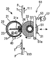
具体的に、図1や図7を参照して、加熱部材22の開口部22aを構成する一端部と他端部それぞれに形成されたL字状の曲げ部に規制孔22bを加熱部材22の長手方向に複数箇所設けており、それら規制孔22bに対応させて、固定部材26に突起形状である規制部26aを固定部材26の長手方向に複数箇所設けている。
Specifically, referring to FIG. 1 and FIG. 7, the
規制孔22bと規制部26aとがそれぞれ対応した位置に配置されているため、加熱部材22と固定部材26とが組み付いた状態では、加熱部材22の一端部及び他端部に設けられた規制孔22bの規制面22cと、固定部材26に設けられた規制部26aの規制面26bとが係合して、固定部材26により加熱部材22の一端部と他端部とを連結するので、加熱部材22の一端部と他端部とが離れていくように加熱部材22の開口部22aが開くのを防止することができる。
Since the
これにより、加熱部材22の長手方向の一部分でも開口部22aが開いたり変形したりすると、加熱部材22と定着ベルト21とが摺接する面積が大きくなって定着ベルト21の摩耗が加速するといった不具合が生じるのを抑制することができる。
As a result, when the
また、加熱部材22に設けられた規制孔22bの規制面22cと、固定部材26に設けられた規制部26aの規制面26bとを、加熱部材22や固定部材26の長手方向の複数箇所で係合させているので、固定部材26の長手方向における部分的な変形や開きを抑制することができる。
Further, the
また、固定部材26には補強部材23に突き当てる突き当て部26cがあり、加圧ローラ31からの圧力を固定部材26の長手方向の全面で受けている。固定部材26の突き当て部26cと補強部材23とを部分的に突き当てた状態で構成すると、突き当ててない部分で加圧ローラ31からの加圧力を十分受けることができなくなり、面圧低下に起因する画質不良が発生する。これを抑制するためには、固定部材26の突き当て部26cと補強部材23とが、少なくとも装置で使用可能な用紙Pの最大用紙幅以上の全面で突き当たっていることが望ましい。
The fixing
さらに、固定部材26の突き当て部26cは加圧ローラ31から定着ベルト21を介して加圧ローラ31の回転動作による摩擦力を受けるが、側板43に固定支持されている補強部材23と突き当て部26cとが固定部材26の長手方向全域で係合しているので、固定部材26は摩擦力による変形が生じない。
Further, the abutting portion 26 c of the fixing
また、図1を参照して、本実施形態では、加熱部材22の開口部22aにはL字状の曲げ部と固定部材26とに一定のクリアランスを設けて挿設されている。加熱部材22に設けられた規制孔22bの規制面22cと、固定部材26に設けられた規制部26aの規制面26bとは係合しているが、加圧ローラ31の加圧方向に対しては、加熱部材22が加圧ローラ31の加圧力の影響を受けて変形することを抑制している。すわなち、加熱部材22と固定部材26とは、加熱部材22に設けられた規制孔22bの規制面22cと、固定部材26に設けられた規制部26aの規制面26b以外は接触していない構成となっている。
Referring to FIG. 1, in the present embodiment, an opening 22 a of the
ステンレス鋼板等の金属板を曲げ加工することにより形成するパイプ状の加熱部材22は、その肉厚を薄くすることができるため熱容量が小さくなり、ウォームアップ時間を短縮することができる。しかしながら、肉厚を薄くすると加熱部材22の剛性が小さくなるため、加圧ローラ31の加圧力が加熱部材22に作用すると、その加圧力に抗しきれずに加熱部材22が撓んだり変形したりしてしまう。パイプ状の加熱部材22が変形してしまうと、所望のニップ幅が得られず定着性が低下するという問題が生じてしまう。
Since the pipe-shaped
これに対して、本実施形態では、薄肉の加熱部材22に加圧ローラ31の加圧力が作用しないように構成しているため、前述したような問題が生じるのを未然に防止することができる。
On the other hand, in the present embodiment, since the pressing force of the
図8は、加熱部材22と定着ベルト21とを幅方向に見た図であって、加熱部材22の加熱変形の状態を示す模式図である。
FIG. 8 is a view of the
図8(a)及び図8(b)に示すように、加熱部材22は、常温状態から加熱されることにより加熱変形が生じて撓むことになる。したがって、常温時に加熱部材22と定着ベルト21との間に設けられていたクリアランス量Aは、加熱時において加熱部材22の変形量Bに応じて減ぜられることになる。
As shown in FIGS. 8A and 8B, the
そして、通常の場合(後述する可逆変化が生じる条件で加熱や冷却が行われるる場合)には、加熱状態にある加熱部材22が冷却されて常温状態になると、クリアランス量Aは常温時のものに戻ることになる。
In a normal case (when heating or cooling is performed under a condition that causes a reversible change to be described later), when the
なお、加熱部材22と定着ベルト21との常温時におけるクリアランス量Aとは、図8(a)に示すように、常温時における加熱部材22の外径と定着ベルト21の内径との差(部分的な差異がある場合には、その最小値)である。また、加熱部材22の変形量Bとは、図8(b)に示すように、加熱部材22の径方向の撓み量であって、常温状態からの撓み量である。
The clearance amount A between the
ここで、ヒータ25によって加熱部材22が常温状態から加熱されたとき(図8(a)の状態から図8(b)の状態へ変化する場合)に、加熱部材22に生じる変形量Bの変動は、次のようなものである。
Here, when the
まず、ウォーミングアップ時等において、常温状態またはそれに近い状態にある加熱部材22の加熱がヒータ25によって開始されるが、その加熱は定着ベルト21を目標の定着温度(140[℃]〜180[℃]程度)に昇温させるためのものであって、比較的急激な加熱である。したがって、加熱部材22の温度分布は、特に加熱開始直後に、全体的に不均質なものになる。
First, at the time of warming up or the like, heating of the
具体的には、加熱部材22の厚み方向において、ヒータ25から遠い側(外周面側)の温度は近い側(内周面側)の温度に比べて低くなり、厚み方向に比較的大きな温度勾配が生じる。これにより、加熱部材22に部分的な熱膨張差が生じて、加熱部材22に熱変形(加熱変形)による撓みが生じる。そのときに、加熱部材22に生じる最大の変形量をBmaxとする。
Specifically, in the thickness direction of the
しかし、その後に、通紙(定着工程)がおこなわれる準備が完了して、定着ベルト21の定着温度が目標値近傍に安定すると、加熱部材22の厚み方向の温度勾配がウォームアップ時よりも小さくなり加熱部材22の温度が全体的に均質化されて、加熱部材22の変形量Bはウォームアップ時よりも小さくなり安定的な変形量Baveが維持される。
However, when preparation for paper passing (fixing process) is completed thereafter and the fixing temperature of the fixing
ここで、本実施形態では、定着ベルト21と加熱部材22との常温時におけるクリアランス量をAとして、ヒータ25によって常温状態から加熱開始されたときに加熱部材22に生じる最大の変形量をBmax(適宜に、「最大変形量」と呼ぶ)として、その後に加熱部材22の温度が全体的に均質化されたときに加熱部材22に生じる安定的な変形量をBave(適宜に、「安定時変形量」と呼ぶ)としたときに、Bmax≧A>Baveの関係を満たすように設定している。
In this embodiment, the clearance amount at normal temperature between the fixing
具体的には、上式の関係が成立するように、定着ベルト21の内径や加熱部材22の外径(クリアランス量A)、加熱部材22の材料や厚さ、定着温度等の定着条件、熱源の種類等が設定される。
Specifically, the inner diameter of the fixing
本実施形態では、定着ベルト21の内径が30[mm]であって、加熱部材22の外径が29.5[mm]であり、クリアランス量Aが0.5[mm](=30[mm]−29.5[mm])に設定されている。
In this embodiment, the inner diameter of the fixing
加熱部材22の材料として、厚さが0.1[mm]のステンレス鋼(SUS430)を用いている。熱源としてヒータ25を用いて、目標とする定着温度(制御上の狙い値)を180[℃]としている。
As the material of the
これにより、加熱部材22の最大の変形量Bmaxが1.3[mm]となり、安定時の変形量Baveが0.4[mm]となり、上式を満足する構成に設定した。このように設定することにより、クリアランス量Aと最大の変形量Bmaxとの関係(Bmax≧A)から、定着ベルト21が静止状態にあるウォーミングアップ時には加熱部材22が定着ベルト21の内周面に強く接触することになり、空気を介することなく加熱部材22から定着ベルト21への熱伝導が積極的におこなわれるため、定着ベルト21の加熱効率が向上することになる。
As a result, the maximum deformation amount Bmax of the
具体的には、加熱部材22が定着ベルト21から離れた状態でウォーミングアップがおこなわれる場合に比べて、定着ベルト21の昇温時間が短縮されることになる。
Specifically, the heating time of the fixing
また、クリアランス量Aと安定時の変形量Baveとの関係(A>Bave)から、定着ベルト21が回転状態(走行状態)にある通紙時(定着工程時)には、加熱部材22が定着ベルト21の内周面に対して微小なクリアランスをあけて対向するか、接触するにしても極めて弱い力で接触することになり、定着ベルト21や加熱部材22の摩耗を低減しつつ、定着ベルト21を効率的に加熱することができる。
Further, from the relationship between the clearance amount A and the stable deformation amount Bave (A> Bave), the
ここで、本願発明者は、鋭意研究を重ねた結果、以下のことを知得した。
すなわち、加熱部材22の加熱効率の向上(熱容量の低下)を達成するために加熱部材22の厚さを0.1[mm]以下に設定した場合に、加熱部材22に非可逆変化による加熱変形が生じてしまう金属材料が多い。
Here, as a result of intensive studies, the present inventor has learned the following.
That is, when the thickness of the
この「非可逆変化」による加熱変形とは、図9に示すように、加熱と冷却とを繰り返しても加熱時に生じた加熱部材22の撓み(変形量B)が常温時に元通りになる「可逆変化」とは異なり、加熱と冷却とを繰り返しても加熱時に生じた加熱部材22の撓みが常温時に元通りにならずに塑性変形として残る現象(このような現象を「折れ現象」という)である。
As shown in FIG. 9, the heat deformation caused by this “irreversible change” is “reversible” in which the deflection (deformation amount B) of the
このように加熱部材22に折れ現象が生じると、通紙時において定着ベルト21の内周面に加熱部材22が局所的に強く接触して、定着ベルト21の内周面が削れてしまったり、定着ベルト21の表面温度にムラが生じて出力画像に定着不良や光沢ムラが発生してしまったりしてしまう。
When the bending phenomenon occurs in the
そして、本願発明者は、このような加熱部材22の非可逆変化による加熱変形(折れ現象)を抑制するためには、加熱部材22の硬度を最適化することが良いことを知得した。詳しくは、加熱部材22の硬度が高すぎる場合には、加熱部材22が熱変形に抗しきれずに折れ現象が生じてしまう。これに対して、加熱部材22の硬度が比較的低い場合には、加熱部材22が熱変形しても弾性的に復元する余地があるため、可逆的な熱変形となる。
The inventor of the present application has found that it is preferable to optimize the hardness of the
図10は、加熱部材22のビッカース硬さ(Hv)と、加熱部材22に折れ現象が生じる温度との関係を実験で求めた結果を示すグラフである。
FIG. 10 is a graph showing the results of experiments to determine the relationship between the Vickers hardness (Hv) of the
この実験は、ビッカース硬さの異なる種々の金属部材(いずれも厚さ0.1[mm]のものである)の表面に定着ベルト21(金属部材側から、ニッケル層35[μm]、シリコーンゴム層200[μm]、PFA層15[μm]が順次積層されたものである。)を貼り付けた実験ピースをいくつか作製して、金属部材を急激に所定温度まで加熱したときに折れ現象が生じるかを判定したものである。 In this experiment, the fixing belt 21 (from the metal member side, nickel layer 35 [μm], silicone rubber) on the surface of various metal members having different Vickers hardness (all having a thickness of 0.1 [mm]) The layer 200 [μm] and the PFA layer 15 [μm] are sequentially laminated.) When several experimental pieces are pasted and the metal member is rapidly heated to a predetermined temperature, the bending phenomenon occurs. It is determined whether it occurs.
図10において、横軸は金属部材のビッカース硬さを示しており、縦軸は定着ベルト21の表面温度(PFA層側の温度である。)を示す。また、図10において、「●」は折れ現象が生じなかった結果を示し、「×」は折れ現象が生じた結果を示すものである。 10, the horizontal axis indicates the Vickers hardness of the metal member, and the vertical axis indicates the surface temperature of the fixing belt 21 (the temperature on the PFA layer side). In FIG. 10, “●” indicates a result in which the folding phenomenon does not occur, and “x” indicates a result in which the folding phenomenon occurs.
例えば、ビッカース硬さが約Hv300の金属部材からなる加熱部材22は、定着ベルト21の温度が約190[℃]になるように急激に加熱した場合に折れ現象が発生することはなかったが、定着ベルト21の温度が約210[℃]になるように急激に加熱した場合には折れ現象が発生した。
For example, the
図10に示す実験結果から、ビッカース硬さがHv280以下の金属部材からなる加熱部材22を用いた場合には、定着温度の設定値に関わらず、加熱部材22に折れ現象が生じないことがわかる。
From the experimental results shown in FIG. 10, it is understood that when the
また、ビッカース硬さがHv340以下の金属部材からなる加熱部材22を用いた場合であっても、定着温度を180[℃]以下に設定すれば、加熱部材22に折れ現象が生じないことがわかる。
Further, even when the
このような実験結果を反映して、本実施形態における定着装置20では、加熱部材22の厚さを0.1[mm]以下に設定して、ビッカース硬さがHv280以下となる金属部材にて加熱部材22を形成している。
Reflecting such experimental results, in the fixing
具体的には、加熱部材22の材料として、単位体積の熱容量比が比較的小さなフェライト系ステンレス鋼であるSUS430(密度:7.73×10⁻³[kg/m3]、比熱:0.46[kJ/kg℃]、ヤング率:206[GPa]、ビッカース硬さ:Hv250、単位体積の熱容量比:3.56)を用いている。これにより、加熱部材22の加熱効率が高くなるとともに、加熱部材22に折れ現象が生じるのを抑制することができる。
Specifically, as a material of the
ちなみに、ニッケルの特性値は、密度:8.9×10⁻³[kg/m3]、比熱:0.439[kJ/kg℃]、ヤング率:210[GPa]、ビッカース硬さ:Hv96、単位体積の熱容量比:3.91である。 Incidentally, the characteristic values of nickel are as follows: density: 8.9 × 10 −3 [kg / m 3 ], specific heat: 0.439 [kJ / kg ° C.], Young's modulus: 210 [GPa], Vickers hardness: Hv96, Heat capacity ratio of unit volume: 3.91.
また、SUS304−1/2Hの特性値は、密度:7.93×10−3[kg/m3]、比熱:0.502[kJ/kg℃]、ヤング率:197[GPa]、ビッカース硬さ:Hv250、単位体積の熱容量比:3.98である。 The characteristic values of SUS304-1 / 2H are: density: 7.93 × 10 −3 [kg / m 3 ], specific heat: 0.502 [kJ / kg ° C.], Young's modulus: 197 [GPa], Vickers hardness S: Hv250, heat capacity ratio of unit volume: 3.98.
以上説明したように、本実施形態においては、定着ベルト21の内周面側に設置する加熱部材22が、加熱開始されるウォームアップ時には最大の変形量Bmaxにて変形して、通紙時には比較的小さな変形量Baveにて安定的な変形状態を維持する性質を利用して、加熱部材22と定着ベルト21とのクリアランス量Aを最適化している。これにより、ウォームアップ時間やファーストプリント時間が短くて、定着装置20を高速化した場合であっても定着不良等が生じることなく、定着ベルト21の加熱効率が充分に高くて、稼動時に定着ベルト21と加熱部材22とが摺接して摩耗する不具合を軽減することができる。
As described above, in the present embodiment, the
以上、本実施形態によれば、回転可能に支持された駆動回転体である加圧ローラ31と、加圧ローラ31を回転駆動させる駆動手段と、加圧ローラ31に対向して回転可能に設けられ可撓性を有する無端状のベルト部材である定着ベルト21と、加圧ローラ31を定着ベルト21に向かって付勢して加圧ローラ31を定着ベルト21に圧接させる付勢手段である接離機構50と、定着ベルト21を介して加圧ローラ31からの加圧を受ける加圧受け部材である固定部材26と、定着ベルト21の内周面側に設けられた熱源であるヒータ25と、定着ベルト21の内周面側に設けられ、板金を一端部と他端部とが対向するように曲げて管状に形成し加圧ローラ31と対向する位置に固定部材26が配置される開口が設けられた、ヒータ25からの熱を受けて定着ベルト21を加熱する加熱部材22とを備えた定着装置20において、固定部材26に設けられた係合部である規制部26aと、加熱部材22の一端部及び他端部に設けられた被係合部である規制孔22bとを係合させて、固定部材26により前記一端部と前記他端部とを連結したことで、加熱部材22の一端部と他端部とが離れていくように開くのを抑制できる。これにより、加熱部材22と定着ベルト21とが強く摺擦し合うのを抑制することができる。また、前記一端部と前記他端部とを連結するため専用の部材を別途設ける場合よりも、部品点数や組立工数を低減させることができ、その分、低コスト化を図ることができる。また、所望の形状の加熱部材22を形成することが可能となり、定着ベルト21の一部のみが局所的に加熱されるのではなく、加熱部材22によって定着ベルト21が周方向にわたってほぼ全体的に加熱されることになるので、装置を高速化した場合であっても定着ベルト21が充分に加熱されて定着不良の発生を抑制することができる。
また、本実施形態によれば、固定部材26に設けられた規制部26aは突起形状であり、加熱部材22の一端部及び他端部に設けられた規制孔22bは孔形状であり、規制部26aが規制孔22bの内周面である規制面22cに接して規制部26aと規制孔22bとが係合する。これにより、加熱部材22に設けられた規制孔22bの規制面22cと、固定部材26に設けられた規制部26aの規制面26bとが係合して、加熱部材22の前記一端部と前記他端部とが離れる方向に開くのを規制部26aと規制孔22bとで規制することができ、加熱部材22の開口部22aが開くのを防止することができる。
また、本実施形態によれば、固定部材26及び加熱部材22は、規制部26aと規制孔22b以外では接しないことで、薄肉の加熱部材22に加圧ローラ31の加圧力が作用するのが抑えられるので、加圧ローラ31からの加圧力がパイプ状の加熱部材22に作用し加熱部材22が変形して、所望のニップ幅が得られずに、定着性が低下してしまうのを抑制することができる。
また、本実施形態によれば、固定部材26に設けられた規制部26aと、加熱部材22に設けられた規制孔22bとを、長手方向に複数設けたことで、長手幅全域で所望の形状の加熱部材22を形成することが可能となり、定着ベルト21の一部のみが局所的に加熱されるのではなく、加熱部材22によって定着ベルト21が周方向にわたってほぼ全体的に加熱されることになるので、装置を高速化した場合であっても定着ベルト21が充分に加熱されて定着不良の発生を抑制することができる。
また、本実施形態によれば、固定部材26が耐熱性の樹脂で形成されていることで、ウォームアップ時間やファーストプリント時間が短く、定着装置20を高速化した場合であっても、定着不良などが生じることなく、定着ベルト21の加熱効率が充分に高くて、稼動時に定着ベルト21と加熱部材22とが摺接して摩耗するのを低減させることができる。
また、本実施形態によれば、加熱部材22は金属製であり肉厚が0.2[mm]以下であることで、加熱部材22や定着ベルト21の加熱効率を向上することができる。よって、ウォームアップ時間やファーストプリント時間が短く、定着装置20を高速化した場合であっても、定着不良などが生じることなく、定着ベルト21の加熱効率が充分に高くて、稼動時に定着ベルト21と加熱部材22とが摺接して摩耗するのを低減させることができる。
また、本実施形態によれば、加熱部材22のビッカース硬さがHv280以下であることで、定着温度の設定値に関わらず、加熱部材22に折れ現象が生じるのを抑制できる。よって、ウォームアップ時間やファーストプリント時間が短く、定着装置20を高速化した場合であっても、定着不良などが生じることなく、定着ベルト21の加熱効率が充分に高くて、稼動時に定着ベルト21と加熱部材22とが摺接して摩耗するのを低減させることができる。
また、本実施形態によれば、加熱部材22がフェライト系ステンレス鋼からなることで、加熱部材22の加熱効率が高くなるとともに、加熱部材22に折れ現象が生じるのを抑制することができる。よって、ウォームアップ時間やファーストプリント時間が短く、定着装置20を高速化した場合であっても、定着不良などが生じることなく、定着ベルト21の加熱効率が充分に高くて、稼動時に定着ベルト21と加熱部材22とが摺接して摩耗するのを低減させることができる。
また、本実施形態によれば、加熱部材22の内周側に設けられ固定部材26に当接して固定部材26を補強する補強部材23を有しており、固定部材26を補強部材23に長手方向で、装置で使用可能な用紙Pの最大用紙幅以上の長さ全面で当接していることで、長手幅全域で所望の形状の加熱部材22を形成することが可能となり、定着ベルト21の一部のみが局所的に加熱されるのではなく、加熱部材22によって定着ベルト21が周方向にわたってほぼ全体的に加熱されることになるので、装置を高速化した場合であっても定着ベルト21が充分に加熱されて定着不良の発生を抑制することができる。
また、本実施形態によれば、記録媒体である用紙Pに対して画像を形成する画像形成部である作像部4と、作像部4で形成された用紙P上の画像を定着させる定着手段とを備えた画像形成装置において、前記定着手段として、本発明の定着装置20を用いたことにより、所望の形状の加熱部材22を形成することが可能となり、定着ベルト21の一部のみが局所的に加熱されるのではなく、加熱部材22によって定着ベルト21が周方向にわたってほぼ全体的に加熱されることになるので、装置を高速化した場合であっても定着ベルト21が充分に加熱されて定着不良の発生を抑制することができる。また、固定部材26に設けられた規制部26aと、加熱部材22の一端部及び他端部に設けられた規制孔22bとを係合させて、固定部材26により前記一端部と前記他端部とを連結するので、前記一端部と前記他端部とを連結するため専用の部材を別途設ける場合よりも、部品点数や組立工数を低減させることができ、その分、低コスト化を図ることができる。
As described above, according to the present embodiment, the
Further, according to the present embodiment, the restricting
In addition, according to the present embodiment, the fixing
Further, according to the present embodiment, a plurality of
Further, according to the present embodiment, the fixing
Further, according to the present embodiment, the
Further, according to the present embodiment, since the Vickers hardness of the
In addition, according to the present embodiment, the
Further, according to the present embodiment, the reinforcing
Further, according to the present embodiment, the image forming unit 4 that is an image forming unit that forms an image on the paper P that is a recording medium, and the fixing that fixes the image on the paper P formed by the image forming unit 4. By using the fixing
1 プリンタ本体
3 露光部
4 作像部
5 感光体ドラム
12 給紙部
20 定着装置
21 定着ベルト
21a 内周面
22 加熱部材
22a 開口部
22b 規制孔
22c 規制面
23 補強部材
25 ヒータ
26 固定部材
26a 規制部
26b 規制面
26c 突き当て部
28 摺動シート
31 加圧ローラ
32 芯金
33 弾性層
40 温度センサ
42 軸受
43 側板
45 ギア
50 接離機構
51 加圧レバー
51a 支軸
52 偏心カム
53 加圧スプリング
75 帯電装置
76 現像装置
77 クリーニング装置
78 中間転写ベルト
79 1次転写バイアスローラ
80 中間転写クリーニング装置
82 2次転写バックアップローラ
83 クリーニングバックアップローラ
84 テンションローラ
85 中間転写ユニット
89 2次転写ローラ
97 給紙ローラ
98 レジストローラ対
99 排紙ローラ対
100 スタック部
101 ボトル収容部
102 トナーボトル
DESCRIPTION OF
Claims (10)
前記駆動回転体を回転駆動させる駆動手段と、
前記駆動回転体に対向して回転可能に設けられ可撓性を有する無端状のベルト部材と、
前記駆動回転体を前記ベルト部材に向かって付勢して該駆動回転体を該ベルト部材に圧接させる付勢手段と、
前記ベルト部材を介して前記駆動回転体からの加圧を受ける加圧受け部材と、
前記ベルト部材の内周面側に設けられた熱源と、
前記ベルト部材の内周面側に設けられ、板金を一端部と他端部とが対向するように曲げて管状に形成し前記駆動回転体と対向する位置に前記加圧受け部材が配置される開口が設けられた、前記熱源からの熱を受けて前記ベルト部材を加熱する加熱部材とを備えた定着装置において、
前記加圧受け部材に設けられた係合部と、前記加熱部材の一端部及び他端部に設けられた被係合部とを係合させて、前記加圧受け部材により前記一端部と前記他端部とを連結したことを特徴とする定着装置。 A driving rotating body supported rotatably;
Drive means for rotationally driving the drive rotator;
An endless belt member that is rotatably provided to face the drive rotator and has flexibility;
Urging means for urging the drive rotator toward the belt member to press the drive rotator against the belt member;
A pressure receiving member that receives pressure from the driving rotating body via the belt member;
A heat source provided on the inner peripheral surface side of the belt member;
Provided on the inner peripheral surface side of the belt member, the sheet metal is bent so that one end and the other end face each other and formed into a tubular shape, and the pressure receiving member is disposed at a position facing the drive rotating body. In a fixing device including an opening, and a heating member that heats the belt member by receiving heat from the heat source,
The engagement portion provided on the pressure receiving member is engaged with the engaged portions provided on one end and the other end of the heating member, and the one end and the above are received by the pressure receiving member. A fixing device having the other end connected thereto.
上記加圧受け部材に設けられた上記係合部は突起形状であり、
上記加熱部材の一端部及び他端部に設けられた上記被係合部は孔形状であり、
前記係合部が前記被係合部の内周面に接して該係合部と該被係合部とが係合することを特徴とする定着装置。 The fixing device according to claim 1.
The engaging portion provided on the pressure receiving member has a protruding shape,
The engaged portions provided at one end and the other end of the heating member have a hole shape,
The fixing device, wherein the engaging portion is in contact with an inner peripheral surface of the engaged portion, and the engaging portion and the engaged portion are engaged with each other.
上記加圧受け部材及び上記加熱部材は、上記係合部と上記被係合以外では接しないことを特徴とする定着装置。 The fixing device according to claim 1 or 2,
The fixing device, wherein the pressure receiving member and the heating member are not in contact with the engaging portion except for the engaged portion.
上記加圧受け部材に設けられた上記係合部と、上記加熱部材に設けられた上記被係合部とを、長手方向に複数設けたことを特徴とする定着装置。 The fixing device according to claim 1, 2 or 3.
A fixing device comprising a plurality of engaging portions provided on the pressure receiving member and a plurality of engaged portions provided on the heating member in a longitudinal direction.
上記加圧受け部材は耐熱性の樹脂で形成されていることを特徴とする定着装置。 The fixing device according to claim 1, 2, 3 or 4.
The fixing device, wherein the pressure receiving member is formed of a heat resistant resin.
上記加熱部材は金属製であり肉厚が0.2[mm]以下であることを特徴とする定着装置。 The fixing device according to claim 1, 2, 3, 4 or 5.
The fixing device according to claim 1, wherein the heating member is made of metal and has a thickness of 0.2 [mm] or less.
上記加熱部材のビッカース硬さがHv280以下であることを特徴とする定着装置。 The fixing device according to claim 1, 2, 3, 4, 5 or 6.
The fixing device according to claim 1, wherein the heating member has a Vickers hardness of Hv280 or less.
上記加熱部材がフェライト系ステンレス鋼からなることを特徴とする定着装置。 The fixing device according to claim 1, 2, 3, 4, 5, 6 or 7.
The fixing device, wherein the heating member is made of ferritic stainless steel.
上記加熱部材の内周側に設けられ上記加圧受け部材に当接して該加圧受け部材を補強する補強部材を有しており、
前記加圧受け部材を前記補強部材に長手方向で、装置で使用可能な記録媒体の最大幅以上の長さ全面で当接していることを特徴とする定着装置。 The fixing device according to claim 1, 2, 3, 4, 5, 6, 7 or 8.
A reinforcing member provided on the inner peripheral side of the heating member to reinforce the pressure receiving member in contact with the pressure receiving member;
The fixing device, wherein the pressure receiving member is in contact with the reinforcing member in the longitudinal direction over the entire length of the maximum width of the recording medium usable in the apparatus.
前記画像形成部で形成された前記記録媒体上の画像を定着させる定着手段とを備えた画像形成装置において、
前記定着手段として、請求項1、2、3、4、5、6、7、8または9の定着装置を用いたことを特徴とする画像形成装置。 An image forming unit that forms an image on a recording medium;
An image forming apparatus comprising: a fixing unit configured to fix the image on the recording medium formed by the image forming unit;
An image forming apparatus using the fixing device according to claim 1, 2, 3, 4, 5, 6, 7, 8, or 9 as the fixing unit.
Priority Applications (2)
| Application Number | Priority Date | Filing Date | Title |
|---|---|---|---|
| JP2011003396A JP5582410B2 (en) | 2011-01-11 | 2011-01-11 | Fixing apparatus and image forming apparatus |
| US13/346,061 US8693936B2 (en) | 2011-01-11 | 2012-01-09 | Fixing device and image forming apparatus incorporating same |
Applications Claiming Priority (1)
| Application Number | Priority Date | Filing Date | Title |
|---|---|---|---|
| JP2011003396A JP5582410B2 (en) | 2011-01-11 | 2011-01-11 | Fixing apparatus and image forming apparatus |
Publications (2)
| Publication Number | Publication Date |
|---|---|
| JP2012145715A JP2012145715A (en) | 2012-08-02 |
| JP5582410B2 true JP5582410B2 (en) | 2014-09-03 |
Family
ID=46455353
Family Applications (1)
| Application Number | Title | Priority Date | Filing Date |
|---|---|---|---|
| JP2011003396A Expired - Fee Related JP5582410B2 (en) | 2011-01-11 | 2011-01-11 | Fixing apparatus and image forming apparatus |
Country Status (2)
| Country | Link |
|---|---|
| US (1) | US8693936B2 (en) |
| JP (1) | JP5582410B2 (en) |
Families Citing this family (18)
| Publication number | Priority date | Publication date | Assignee | Title |
|---|---|---|---|---|
| JP5850391B2 (en) | 2011-09-12 | 2016-02-03 | 株式会社リコー | Fixing apparatus and image forming apparatus |
| JP6069950B2 (en) * | 2012-08-21 | 2017-02-01 | 株式会社リコー | Fixing apparatus and image forming apparatus |
| JP2014056154A (en) | 2012-09-13 | 2014-03-27 | Ricoh Co Ltd | Fixing device and image forming apparatus |
| JP6028500B2 (en) | 2012-10-02 | 2016-11-16 | 株式会社リコー | Fixing apparatus and image forming apparatus |
| JP6028504B2 (en) | 2012-10-04 | 2016-11-16 | 株式会社リコー | Fixing apparatus and image forming apparatus |
| JP6127444B2 (en) * | 2012-10-23 | 2017-05-17 | 株式会社リコー | Fixing apparatus and image forming apparatus |
| JP6107090B2 (en) | 2012-12-04 | 2017-04-05 | 株式会社リコー | Fixing apparatus and image forming apparatus |
| JP6083218B2 (en) | 2012-12-05 | 2017-02-22 | 株式会社リコー | Fixing apparatus and image forming apparatus |
| JP6337621B2 (en) | 2014-06-03 | 2018-06-06 | 株式会社リコー | Fixing apparatus and image forming apparatus |
| JP2016038545A (en) | 2014-08-11 | 2016-03-22 | 株式会社リコー | Image forming apparatus |
| JP6481958B2 (en) | 2014-10-02 | 2019-03-13 | 株式会社リコー | Belt device, fixing device and image forming apparatus |
| JP6474029B2 (en) | 2014-12-25 | 2019-02-27 | 株式会社リコー | Fixing apparatus and image forming apparatus |
| JP6547947B2 (en) | 2015-06-23 | 2019-07-24 | 株式会社リコー | Separation member, fixing device and image forming apparatus |
| JP6579366B2 (en) | 2015-07-02 | 2019-09-25 | 株式会社リコー | Fixing apparatus and image forming apparatus |
| JP2018116083A (en) | 2017-01-16 | 2018-07-26 | 富士ゼロックス株式会社 | Fixation device and image formation apparatus |
| US10558154B1 (en) * | 2018-07-27 | 2020-02-11 | Ricoh Company, Ltd. | Image forming apparatus incorporating pressing device |
| EP3629097A1 (en) * | 2018-09-27 | 2020-04-01 | Ricoh Company, Ltd. | Fixing device and image forming apparatus incorporating the same |
| CN114036677B (en) * | 2021-11-15 | 2023-04-28 | 中国空气动力研究与发展中心超高速空气动力研究所 | Method for analyzing bearing capacity of plate steel structure |
Family Cites Families (49)
| Publication number | Priority date | Publication date | Assignee | Title |
|---|---|---|---|---|
| US5148226A (en) * | 1990-06-11 | 1992-09-15 | Canon Kabushiki Kaisha | Heating apparatus using endless film |
| US6122478A (en) * | 1999-08-04 | 2000-09-19 | Hewlett-Packard Company | Reduction of thermally induced mechanical stress in a fixing device |
| JP3957968B2 (en) * | 2000-11-24 | 2007-08-15 | 株式会社リコー | Fixing apparatus and image forming apparatus having the same |
| JP2003057981A (en) * | 2001-08-17 | 2003-02-28 | Nitto Kogyo Co Ltd | Fixing device |
| JP2003223063A (en) * | 2002-01-30 | 2003-08-08 | Matsushita Electric Ind Co Ltd | Fixation device |
| JP4576883B2 (en) * | 2004-05-18 | 2010-11-10 | 富士ゼロックス株式会社 | Fixing device and image forming apparatus for electrophotographic system |
| JP4643324B2 (en) | 2005-03-18 | 2011-03-02 | 株式会社リコー | Image forming apparatus |
| JP2006259639A (en) | 2005-03-18 | 2006-09-28 | Ricoh Co Ltd | Image forming apparatus |
| JP4628854B2 (en) | 2005-04-27 | 2011-02-09 | 株式会社リコー | Image forming apparatus |
| JP4452670B2 (en) | 2005-09-20 | 2010-04-21 | 株式会社リコー | Paper transport device, image forming device, image reading device, automatic document feeder |
| US7599633B2 (en) | 2005-11-15 | 2009-10-06 | Ricoh Company, Ltd. | Image forming apparatus dust container including dust conveyance members |
| JP4903433B2 (en) | 2005-12-28 | 2012-03-28 | 株式会社リコー | Image forming apparatus |
| JP2007187700A (en) | 2006-01-11 | 2007-07-26 | Ricoh Co Ltd | Transfer device and image forming apparatus |
| JP2008009377A (en) | 2006-05-30 | 2008-01-17 | Ricoh Co Ltd | Image forming apparatus |
| JP2007328236A (en) | 2006-06-09 | 2007-12-20 | Ricoh Co Ltd | Image forming apparatus |
| US7878725B2 (en) | 2006-06-12 | 2011-02-01 | Ricoh Company, Ltd. | Image forming apparatus having removable units |
| JP2008058563A (en) | 2006-08-31 | 2008-03-13 | Ricoh Co Ltd | Pressing member, fixing device using same, and image forming apparatus |
| JP2008146010A (en) | 2006-11-14 | 2008-06-26 | Ricoh Co Ltd | Fixing device and image forming apparatus |
| US7778573B2 (en) | 2006-12-26 | 2010-08-17 | Ricoh Company, Ltd. | Image forming apparatus and process cartridge |
| JP5106133B2 (en) | 2007-01-24 | 2012-12-26 | 株式会社リコー | Upper structure opening / closing device of image forming apparatus, image forming apparatus, and upper structure opening / closing buffering method of image forming apparatus |
| US8089666B2 (en) | 2007-01-25 | 2012-01-03 | Ricoh Company, Ltd. | Image forming apparatus |
| JP4977630B2 (en) | 2007-01-30 | 2012-07-18 | 株式会社リコー | Image forming apparatus |
| JP4945261B2 (en) | 2007-02-14 | 2012-06-06 | 株式会社リコー | Image forming apparatus |
| JP2008224878A (en) * | 2007-03-09 | 2008-09-25 | Ricoh Co Ltd | Fixing device and image forming apparatus |
| JP5031451B2 (en) | 2007-06-18 | 2012-09-19 | 株式会社リコー | Transfer device and image forming apparatus |
| JP5009067B2 (en) | 2007-07-04 | 2012-08-22 | 株式会社リコー | Fixing apparatus and image forming apparatus |
| US7735634B2 (en) | 2007-07-13 | 2010-06-15 | Ricoh Company, Ltd. | Belt device and image forming apparatus |
| US8233823B2 (en) | 2007-07-13 | 2012-07-31 | Ricoh Company, Limited | Belt device and image forming apparatus |
| US8260186B2 (en) | 2007-07-18 | 2012-09-04 | Ricoh Company, Limited | Toner cartridge with refillable fresh and residual toner chambers, process cartridge, and method of making toner cartridge reusable |
| US7751751B2 (en) | 2007-07-19 | 2010-07-06 | Ricoh Company, Ltd. | Image forming apparatus and damper |
| JP2009031568A (en) * | 2007-07-27 | 2009-02-12 | Ricoh Co Ltd | Fixing device |
| JP2009047913A (en) * | 2007-08-20 | 2009-03-05 | Konica Minolta Business Technologies Inc | Fixing device and image forming apparatus with same |
| JP5110576B2 (en) | 2007-08-31 | 2012-12-26 | 株式会社リコー | Fixing apparatus and image forming apparatus |
| JP5145839B2 (en) | 2007-09-14 | 2013-02-20 | 株式会社リコー | Fixing apparatus and image forming apparatus |
| US8107864B2 (en) | 2007-10-24 | 2012-01-31 | Ricoh Company, Limited | Separating member, fixing device, and image forming apparatus |
| JP2009122563A (en) | 2007-11-19 | 2009-06-04 | Ricoh Co Ltd | Fixing device and image forming apparatus |
| JP5359211B2 (en) | 2007-12-17 | 2013-12-04 | 株式会社リコー | Waste toner collecting device, process cartridge, and image forming apparatus |
| US8103195B2 (en) | 2007-12-20 | 2012-01-24 | Ricoh Company, Ltd. | Toner agitating unit, toner hopper, process cartridge, and image forming apparatus |
| JP4964113B2 (en) | 2007-12-21 | 2012-06-27 | 株式会社リコー | Image forming method |
| JP5277662B2 (en) | 2008-03-03 | 2013-08-28 | 株式会社リコー | Process cartridge, developing device including the same, and image forming apparatus |
| JP5257691B2 (en) | 2008-08-08 | 2013-08-07 | 株式会社リコー | Fixing apparatus and image forming apparatus |
| JP5170842B2 (en) | 2008-10-14 | 2013-03-27 | 株式会社リコー | Fixing apparatus and image forming apparatus |
| JP5435339B2 (en) | 2009-02-05 | 2014-03-05 | 株式会社リコー | Fixing apparatus and image forming apparatus |
| JP5091885B2 (en) * | 2009-02-12 | 2012-12-05 | 株式会社リコー | Fixing apparatus and image forming apparatus |
| JP5428421B2 (en) | 2009-03-16 | 2014-02-26 | 株式会社リコー | Fixing apparatus and image forming apparatus |
| JP5348561B2 (en) * | 2009-05-15 | 2013-11-20 | 株式会社リコー | Fixing apparatus and image forming apparatus |
| EP2284624B1 (en) | 2009-07-29 | 2020-02-26 | Ricoh Company, Ltd. | Fixing Device and Image Forming Apparatus Incorporating Same |
| US8682199B2 (en) | 2009-10-27 | 2014-03-25 | Ricoh Company, Limited | Mechanism for electrifying, method of electrifying, and conductive member |
| JP5429553B2 (en) | 2009-12-16 | 2014-02-26 | 株式会社リコー | Fixing apparatus and image forming apparatus |
-
2011
- 2011-01-11 JP JP2011003396A patent/JP5582410B2/en not_active Expired - Fee Related
-
2012
- 2012-01-09 US US13/346,061 patent/US8693936B2/en not_active Expired - Fee Related
Also Published As
| Publication number | Publication date |
|---|---|
| US8693936B2 (en) | 2014-04-08 |
| US20120177422A1 (en) | 2012-07-12 |
| JP2012145715A (en) | 2012-08-02 |
Similar Documents
| Publication | Publication Date | Title |
|---|---|---|
| JP5582410B2 (en) | Fixing apparatus and image forming apparatus | |
| JP5515906B2 (en) | Fixing apparatus and image forming apparatus | |
| JP5366005B2 (en) | Fixing apparatus and image forming apparatus | |
| JP6069950B2 (en) | Fixing apparatus and image forming apparatus | |
| JP5381746B2 (en) | Fixing apparatus and image forming apparatus | |
| JP5776311B2 (en) | Fixing apparatus and image forming apparatus | |
| JP5408553B2 (en) | Fixing apparatus and image forming apparatus | |
| JP6127444B2 (en) | Fixing apparatus and image forming apparatus | |
| JP5091885B2 (en) | Fixing apparatus and image forming apparatus | |
| JP2011064767A (en) | Fixing device and image forming apparatus | |
| JP2012118488A (en) | Fixing device and image forming apparatus | |
| JP6136147B2 (en) | Fixing apparatus and image forming apparatus | |
| JP2014056154A (en) | Fixing device and image forming apparatus | |
| JP2012145633A (en) | Fixing device and image forming apparatus | |
| JP2014056146A (en) | Fixing device and image forming apparatus | |
| JP6462204B2 (en) | Fixing apparatus and image forming apparatus | |
| JP2013057896A (en) | Fixing device and image forming apparatus | |
| JP2014178533A (en) | Fixing device and image forming apparatus | |
| JP2019008159A (en) | Fixing device and image forming apparatus | |
| JP6864256B2 (en) | Fixing device, image forming device | |
| JP6880500B2 (en) | Fixing device and image forming device | |
| JP5381745B2 (en) | Fixing apparatus and image forming apparatus | |
| JP7377453B2 (en) | Fixing device and image forming device | |
| JP2017146404A (en) | Fixing device and image forming apparatus | |
| JP6860844B2 (en) | Heat transfer device and image forming device |
Legal Events
| Date | Code | Title | Description |
|---|---|---|---|
| A621 | Written request for application examination |
Free format text: JAPANESE INTERMEDIATE CODE: A621 Effective date: 20131202 |
|
| TRDD | Decision of grant or rejection written | ||
| A977 | Report on retrieval |
Free format text: JAPANESE INTERMEDIATE CODE: A971007 Effective date: 20140618 |
|
| A01 | Written decision to grant a patent or to grant a registration (utility model) |
Free format text: JAPANESE INTERMEDIATE CODE: A01 Effective date: 20140620 |
|
| A61 | First payment of annual fees (during grant procedure) |
Free format text: JAPANESE INTERMEDIATE CODE: A61 Effective date: 20140703 |
|
| R151 | Written notification of patent or utility model registration |
Ref document number: 5582410 Country of ref document: JP Free format text: JAPANESE INTERMEDIATE CODE: R151 |
|
| LAPS | Cancellation because of no payment of annual fees |