JP5576399B2 - MONITORING METHOD AND MONITORING DEVICE FOR MONITORING COMBUSTION CHARACTERISTICS IN BOILER INTERNAL SPACE - Google Patents
MONITORING METHOD AND MONITORING DEVICE FOR MONITORING COMBUSTION CHARACTERISTICS IN BOILER INTERNAL SPACE Download PDFInfo
- Publication number
- JP5576399B2 JP5576399B2 JP2011545421A JP2011545421A JP5576399B2 JP 5576399 B2 JP5576399 B2 JP 5576399B2 JP 2011545421 A JP2011545421 A JP 2011545421A JP 2011545421 A JP2011545421 A JP 2011545421A JP 5576399 B2 JP5576399 B2 JP 5576399B2
- Authority
- JP
- Japan
- Prior art keywords
- capture
- collimator lens
- emission
- lens
- observation tube
- Prior art date
- Legal status (The legal status is an assumption and is not a legal conclusion. Google has not performed a legal analysis and makes no representation as to the accuracy of the status listed.)
- Active
Links
Images


Classifications
-
- G—PHYSICS
- G01—MEASURING; TESTING
- G01N—INVESTIGATING OR ANALYSING MATERIALS BY DETERMINING THEIR CHEMICAL OR PHYSICAL PROPERTIES
- G01N21/00—Investigating or analysing materials by the use of optical means, i.e. using sub-millimetre waves, infrared, visible or ultraviolet light
- G01N21/84—Systems specially adapted for particular applications
-
- F—MECHANICAL ENGINEERING; LIGHTING; HEATING; WEAPONS; BLASTING
- F23—COMBUSTION APPARATUS; COMBUSTION PROCESSES
- F23N—REGULATING OR CONTROLLING COMBUSTION
- F23N5/00—Systems for controlling combustion
- F23N5/02—Systems for controlling combustion using devices responsive to thermal changes or to thermal expansion of a medium
- F23N5/08—Systems for controlling combustion using devices responsive to thermal changes or to thermal expansion of a medium using light-sensitive elements
-
- F—MECHANICAL ENGINEERING; LIGHTING; HEATING; WEAPONS; BLASTING
- F23—COMBUSTION APPARATUS; COMBUSTION PROCESSES
- F23M—CASINGS, LININGS, WALLS OR DOORS SPECIALLY ADAPTED FOR COMBUSTION CHAMBERS, e.g. FIREBRIDGES; DEVICES FOR DEFLECTING AIR, FLAMES OR COMBUSTION PRODUCTS IN COMBUSTION CHAMBERS; SAFETY ARRANGEMENTS SPECIALLY ADAPTED FOR COMBUSTION APPARATUS; DETAILS OF COMBUSTION CHAMBERS, NOT OTHERWISE PROVIDED FOR
- F23M5/00—Casings; Linings; Walls
- F23M5/08—Cooling thereof; Tube walls
-
- F—MECHANICAL ENGINEERING; LIGHTING; HEATING; WEAPONS; BLASTING
- F23—COMBUSTION APPARATUS; COMBUSTION PROCESSES
- F23N—REGULATING OR CONTROLLING COMBUSTION
- F23N5/00—Systems for controlling combustion
- F23N5/02—Systems for controlling combustion using devices responsive to thermal changes or to thermal expansion of a medium
- F23N5/08—Systems for controlling combustion using devices responsive to thermal changes or to thermal expansion of a medium using light-sensitive elements
- F23N5/082—Systems for controlling combustion using devices responsive to thermal changes or to thermal expansion of a medium using light-sensitive elements using electronic means
-
- F—MECHANICAL ENGINEERING; LIGHTING; HEATING; WEAPONS; BLASTING
- F24—HEATING; RANGES; VENTILATING
- F24H—FLUID HEATERS, e.g. WATER OR AIR HEATERS, HAVING HEAT-GENERATING MEANS, e.g. HEAT PUMPS, IN GENERAL
- F24H9/00—Details
- F24H9/20—Arrangement or mounting of control or safety devices
-
- G—PHYSICS
- G01—MEASURING; TESTING
- G01B—MEASURING LENGTH, THICKNESS OR SIMILAR LINEAR DIMENSIONS; MEASURING ANGLES; MEASURING AREAS; MEASURING IRREGULARITIES OF SURFACES OR CONTOURS
- G01B11/00—Measuring arrangements characterised by the use of optical techniques
- G01B11/26—Measuring arrangements characterised by the use of optical techniques for measuring angles or tapers; for testing the alignment of axes
- G01B11/27—Measuring arrangements characterised by the use of optical techniques for measuring angles or tapers; for testing the alignment of axes for testing the alignment of axes
-
- G—PHYSICS
- G01—MEASURING; TESTING
- G01N—INVESTIGATING OR ANALYSING MATERIALS BY DETERMINING THEIR CHEMICAL OR PHYSICAL PROPERTIES
- G01N21/00—Investigating or analysing materials by the use of optical means, i.e. using sub-millimetre waves, infrared, visible or ultraviolet light
-
- G—PHYSICS
- G01—MEASURING; TESTING
- G01N—INVESTIGATING OR ANALYSING MATERIALS BY DETERMINING THEIR CHEMICAL OR PHYSICAL PROPERTIES
- G01N21/00—Investigating or analysing materials by the use of optical means, i.e. using sub-millimetre waves, infrared, visible or ultraviolet light
- G01N21/17—Systems in which incident light is modified in accordance with the properties of the material investigated
- G01N21/25—Colour; Spectral properties, i.e. comparison of effect of material on the light at two or more different wavelengths or wavelength bands
- G01N21/31—Investigating relative effect of material at wavelengths characteristic of specific elements or molecules, e.g. atomic absorption spectrometry
- G01N21/39—Investigating relative effect of material at wavelengths characteristic of specific elements or molecules, e.g. atomic absorption spectrometry using tunable lasers
Description
本願の開示内容は、ボイラの内部空間における燃焼特性を測定する測定方法及び測定装置を対象にしており、より具体的には、蒸気管を再構成することなく、金属膜によって隔離された複数の並列の蒸気管を備えた壁部を有するタイプのボイラにおける燃焼特性を測定する測定方法及び測定装置を対象にする。 The disclosure of the present application is directed to a measurement method and a measurement apparatus for measuring combustion characteristics in an internal space of a boiler, and more specifically, a plurality of pieces separated by a metal film without reconfiguring a steam pipe. The present invention is directed to a measurement method and a measurement apparatus for measuring combustion characteristics in a boiler having a wall portion with parallel steam pipes.
「処理のモニタ及び制御のための方法及び装置(Method and Apparatus For The Monitoring And Control Of A Process)」と題する特許文献1は、調整可能ダイオードレーザ吸収分光法(TDLAS)を利用する処理のモニタ及び制御のための方法及び装置について述べている。簡潔に述べると、TDLAS方法及びTDLAS装置において、多数の別個の波長からなる多重ビームでありうる光ビームをボイラ燃焼室へ導くことが行われ、ボイラ燃焼特性、例えばCO、CO2、O2及びH2Oを含む種々の燃焼種の温度及び濃度が測定される。この技術において、ボイラを貫通する視線が要求される。複数のボイラ個所における燃焼特性を測定するのが望ましい場合が多いため、実際に、典型的には多くの視線が要求される。典型的には、波長多重レーザビームが放出光学部(pitch optic)から、ボイラの反対側に在る捕捉光学部(catch optic)まで伝送される。或る適用例では、最大15個の測定経路が要求され、したがって15対の放出光学部及び捕捉光学部並びに30個のボイラ貫通部が要求される。 Patent document 1 entitled “Method and Apparatus For The Monitoring And Control Of A Process” describes a process monitor and tunable diode laser absorption spectroscopy (TDLAS). A method and apparatus for control are described. Briefly, in the TDLAS method and TDLAS apparatus, a light beam, which can be a multiple beam of multiple distinct wavelengths, is directed to a boiler combustion chamber, and boiler combustion characteristics such as CO, CO 2 , O 2 and The temperature and concentration of various combustion species including H 2 O are measured. In this technique, a line of sight that penetrates the boiler is required. In practice, it is typically desirable to have many lines of sight because it is often desirable to measure combustion characteristics at multiple boiler locations. Typically, a wavelength multiplexed laser beam is transmitted from the emission optics to the capture optics on the opposite side of the boiler. In some applications, up to 15 measurement paths are required, thus requiring 15 pairs of emission and capture optics and 30 boiler penetrations.
典型的な石炭ボイラは、金属膜によって離間された一連の並列の蒸気管から形成される壁部を備えている。蒸気管は、典型的には直径約5.08cm(2インチ)であり、中心から約6.35cm(2.5インチ)間隔に存在する。蒸気管の間の金属膜は、典型的には幅約1.27cm(0.5インチ)、肉厚約0.9525cm(0.375インチ)である。波長多重レーザビームを利用して測定用の光学的アクセスを得るために、光学的アクセス部がボイラの壁部を貫通して形成される必要がある。公知のTDLAS装置は、適切な光学的アクセス部を形成するために、直径およそ5.08cm(2インチ)の孔をボイラ壁部に形成することを要求する。 A typical coal boiler has a wall formed from a series of parallel steam pipes separated by a metal film. Steam pipes are typically about 5.08 cm (2 inches) in diameter and are spaced about 2.5 inches from the center. The metal film between the steam tubes is typically about 1.27 cm (0.5 inches) wide and about 0.975 cm (0.375 inches) thick. In order to obtain optical access for measurement using a wavelength multiplexed laser beam, the optical access portion needs to be formed through the wall of the boiler. Known TDLAS devices require holes in the boiler wall to be approximately 5.08 cm (2 inches) in diameter to form a suitable optical access.
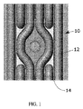
図1は、光学的アクセス部をボイラの内部空間に形成するための現在の技術を示している。図1を参照すると、ボイラ壁部10は、金属膜14によって隔離された一連の並列の蒸気管12を備えている。光学的アクセスのために要求される約5.08cm(2インチ)の孔を形成するために、蒸気管は、図1に示されるような管湾曲部を利用して経路変更される必要がある。いったん完成すれば、光学的アクセスを形成するための管湾曲部の使用は良好に機能する。しかしながら、燃焼状態を十分にモニタするのに要求される数の管湾曲部を設けることは、困難かつ高価である。問題は、単一の管湾曲部を導入するためでさえ、相当な時間の間、ボイラを停止させる必要がある事実から主として発生する。結果として、管湾曲部ひいてはTDLASモニタ部は、長時間の計画的停止の際にしか導入できない。計画的停止は、1年に1回又は2年に1回しか行われない。したがって、タイミングが悪いと、或る発電所がTDLASモニタ部を購入して導入できるようになるまで、最大2年待つ必要があることもある。したがって、ボイラ内における燃焼特性をモニタするためのモニタ装置において、管湾曲部を必要としないものは非常に望ましい。
FIG. 1 shows the current technology for forming an optical access section in the internal space of a boiler. Referring to FIG. 1, the
本発明は、前述した問題の1つ又は2つ以上を解決することを対象とする。 The present invention is directed to overcoming one or more of the problems set forth above.
開示内容の第1の態様は、金属膜によって隔離された複数の並列の蒸気管を備えた壁部を有するタイプのボイラの内部空間における燃焼特性をモニタするためのモニタ方法である。このモニタ方法は、ボイラの両側に在る隣接する蒸気管の間の金属膜に対して、それら隣接する蒸気管を再配置することなく、第1及び第2の貫通部を形成することを含む。次いで、光ビームが、いずれもボイラの内部空間の外側に位置する放出コリメータレンズと放出リレーレンズとを備えた放出光学部を介して投射される。放出リレーレンズは第1の貫通部に光学的に接続され、光ビームをボイラの内部空間へと投射する。このモニタ方法は、ボイラの内部空間の外側に位置する捕捉光学部によって光ビームを受信することをさらに含む。この捕捉光学部は、第2の貫通部に光学的に接続された捕捉リレーレンズと、該捕捉リレーレンズに光学的に接続された捕捉コリメータレンズとを備える。コリメートされた受光ビームの強度が決定される。放出コリメータレンズ及び捕捉コリメータレンズのうちの少なくとも一方は、次いでコリメートされた受光ビームの強度を最大化するように整列されうる。実施形態は、放出コリメータレンズ及び捕捉コリメータレンズの両方が受光ビームの強度を最大化するように整列されることを含みうる。第1及び第2の貫通部は、蒸気管に対して平行に長尺化されていてもよい。このモニタ方法は、放出光学部を放出光学部ハウジング内に、捕捉光学部を捕捉光学部ハウジング内にそれぞれ設置することをさらに含みうるとともに、放出リレーレンズ及び捕捉リレーレンズは、放出光学部ハウジング及び捕捉光学部ハウジングの前縁壁におけるオリフィスをそれぞれ閉塞してもよい。このような実施形態において、このモニタ方法は、第1の観測管及び第2の観測管の基端を外部ボイラ壁部に取付けることをさらに含みうるとともに、第1の貫通部及び第2の貫通部が第1の観測管及び第2の観測管の内部空間にそれぞれ連通していてもよい。放出光学部ハウジングは第1の観測管の末端に取付けられうるとともに、リレーレンズが第1の観測管の内部空間に光学的に連通していてもよく、また、捕捉光学部ハウジングは第2の観測管の末端に取付けられうるとともに、捕捉リレーレンズが第2の観測管の内部空間に光学的に連通していてもよい。 A first aspect of the disclosure is a monitoring method for monitoring combustion characteristics in an interior space of a boiler having a wall portion having a plurality of parallel steam pipes separated by a metal film. The monitoring method includes forming first and second penetrations in a metal film between adjacent steam pipes on both sides of the boiler without rearranging the adjacent steam pipes. . Next, the light beam is projected through an emission optical unit including an emission collimator lens and an emission relay lens, both of which are located outside the internal space of the boiler. The discharge relay lens is optically connected to the first penetration and projects a light beam into the internal space of the boiler. The monitoring method further includes receiving the light beam by a capture optics located outside the boiler interior space. The capture optical unit includes a capture relay lens optically connected to the second penetrating part and a capture collimator lens optically connected to the capture relay lens . The intensity of the collimated received beam is determined. At least one of the emission collimator lens and the capture collimator lens can then be aligned to maximize the intensity of the collimated received beam. Embodiments can include both the emitting collimator lens and the capture collimator lens being aligned to maximize the intensity of the received beam. The first and second penetrating portions may be elongated in parallel with the steam pipe. The monitoring method may further include installing the emission optic in the emission optic housing and the capture optic in the capture optic housing, and the emission relay lens and the capture relay lens include the emission optic housing and Each orifice in the front edge wall of the capture optics housing may be closed. In such an embodiment, the monitoring method may further include attaching the proximal ends of the first observation tube and the second observation tube to the outer boiler wall, and the first penetration portion and the second penetration portion. The units may communicate with the internal spaces of the first observation tube and the second observation tube, respectively. The emission optics housing may be attached to the end of the first observation tube, the relay lens may be in optical communication with the interior space of the first observation tube, and the capture optics housing is the second observation tube. It may be attached to the end of the observation tube, and the capture relay lens may be in optical communication with the internal space of the second observation tube.
開示内容の別の態様は、金属膜によって隔離された複数の並列の蒸気管を備えたボイラの内部空間の燃焼特性を検知するための検知装置である。この検知装置は、選択レーザ発振周波数を有するダイオードレーザを備えている。放出コリメータレンズは、ビームを生成するダイオードレーザに光学的に接続される。放出リレーレンズは、放出コリメータレンズに光学的に接続されるとともに、放出リレーレンズは、ビームをレーザから、隣接する蒸気管の間の第1の膜における第1の貫通部に投射するように構成される。捕捉リレーレンズは、投射されたビームを、第1の膜とは概ね反対の第2の膜における第2の貫通部に通して受信するように構成される。捕捉コリメータレンズは捕捉リレーレンズに光学的に接続され、光ファイバは捕捉コリメータレンズに光学的に接続される。選択レーザ発振周波数に感受性を有する検出器が次いで光ファイバに光学的に接続される。整列機構部は、放出コリメータレンズ及び捕捉コリメータレンズのうちの少なくとも一方に関連付けられていて、検出器によって受信される光量を最大化するように、コリメータレンズをビームに対して整列させる。放出コリメータレンズ及び放出リレーレンズと、捕捉コリメータレンズ及び捕捉リレーレンズとは、第1の態様に関連して説明したように放出ハウジング及び捕捉ハウジングにそれぞれ収容されうる。実施形態は、基端においてボイラの外部空間に取付けられた第1の観測管及び第2の観測管をさらに備えうるとともに、貫通部が観測管の内部空間に連通していてもよい。このような実施形態において、放出ハウジング及び捕捉ハウジングは、第1の観測管及び第2の観測管の末端にそれぞれ取付けられうるとともに、リレーレンズがそれら観測管の内部空間に光学的に接続されてもよい。実施形態は、放出コリメータレンズ及び捕捉コリメータレンズの各々に関連付けられる整列機構部を備えてもよい。この整列機構部は、コリメータレンズを第1の直交軸線及び第2の直交軸線に沿ってチルト動作させるチルト動作手段を備えてもよく、これら第1の直交軸線及び第2の直交軸線は、いずれも投射されるビームに対して概ね直交している。データ処理システムが検出器及び整列機構部に関連付けられてもよい。データ処理システムは検出器からデータを受信するとともに、整列機構部によって関連付けられたコリメータレンズを整列させ、ビームの強度を最大化する。 Another aspect of the disclosure is a detection device for detecting combustion characteristics of an internal space of a boiler having a plurality of parallel steam pipes separated by a metal film. The detection device includes a diode laser having a selected laser oscillation frequency. The emission collimator lens is optically connected to a diode laser that produces the beam. The emission relay lens is optically connected to the emission collimator lens, and the emission relay lens is configured to project the beam from the laser to the first penetration in the first membrane between adjacent vapor tubes. Is done. The capture relay lens is configured to receive the projected beam through a second penetration in a second membrane generally opposite the first membrane. The capture collimator lens is optically connected to the capture relay lens, and the optical fiber is optically connected to the capture collimator lens. A detector sensitive to the selected lasing frequency is then optically connected to the optical fiber. The alignment mechanism is associated with at least one of the emission collimator lens and the capture collimator lens and aligns the collimator lens with respect to the beam so as to maximize the amount of light received by the detector. The emission collimator lens and the emission relay lens and the acquisition collimator lens and the acquisition relay lens can be accommodated in the emission housing and the acquisition housing, respectively, as described in connection with the first aspect. The embodiment may further include a first observation tube and a second observation tube attached to the external space of the boiler at the proximal end, and the penetration portion may be in communication with the internal space of the observation tube. In such an embodiment, the discharge housing and the capture housing can be attached to the ends of the first observation tube and the second observation tube, respectively, and a relay lens is optically connected to the interior space of the observation tubes. Also good. Embodiments may include an alignment mechanism associated with each of the emission collimator lens and the capture collimator lens. The alignment mechanism section may include a tilt operation means for tilting the collimator lens along the first orthogonal axis and the second orthogonal axis, and the first orthogonal axis and the second orthogonal axis are either Is generally orthogonal to the projected beam. A data processing system may be associated with the detector and alignment mechanism. The data processing system receives data from the detector and aligns the collimator lenses associated by the alignment mechanism to maximize the intensity of the beam.
本明細書に記載されるボイラの内部空間における燃焼特性を測定する測定方法及び測定装置は、管湾曲部を導入して光学的アクセスを可能にするためにボイラを停止することを必要とせずに、燃焼特性の検出を可能にする。したがって、この測定方法及び測定装置によって、管湾曲部の導入を要求するシステムに比べて、燃焼モニタ作用における多くの利点が迅速かつ安価に享受される。 The measurement method and measurement apparatus for measuring combustion characteristics in the boiler interior space described herein without introducing a tube bend to allow optical access without having to stop the boiler Enables detection of combustion characteristics. Therefore, by this measuring method and measuring device, many advantages in the combustion monitoring function can be enjoyed quickly and inexpensively as compared with a system that requires the introduction of a tube bending portion.
格別の示唆がされない場合、明細書及び特許請求の範囲において使用される構成要素の数量、寸法、反応条件などを表すあらゆる数字は、あらゆる場合において、用語「約」に基づいて改変されるように理解されるであろう。 Unless otherwise indicated, all numbers representing the quantities, dimensions, reaction conditions, etc. of the components used in the specification and claims are to be modified based on the term “about” in all cases. Will be understood.
本願及び特許請求の範囲において、単数のものが使用される場合は、特に格別の言及がされない場合、複数のものが含まれる。それに加えて、「又は」が使用される場合は、格別の言及がされない場合、「それらの一方或いはそれら両方」を意味する。さらに、用語「含む」が使用されるときは、他の形式、例えば「含んでいる」、「含まれる」と同様に、限定的ではない。また、用語「要素」又は「構成部品」は、特に格別の言及がされない場合、1つのユニットを備える要素及び構成部品と、1つよりも多いユニットを備える要素及び構成部品との両方を包含する。 In this application and in the claims, the use of the singular includes the plural unless specifically stated otherwise. In addition, when “or” is used, it means “one or both of them” unless otherwise stated. Further, when the term “comprising” is used, it is not limiting as is the case with other forms, eg, “includes”, “included”. Also, the term “element” or “component” encompasses both elements and components comprising one unit and elements and components comprising more than one unit unless specifically stated otherwise. .
本明細書において参照することによりその内容全体が本明細書に組入れられる特許文献1は、光学的アクセスをボイラに付与するために、管湾曲部をボイラの壁部に導入することを要求するタイプにおける燃焼過程のモニタ及び制御のための方法及び装置を開示する。特許文献1は、放出光学部及び捕捉光学部が、ボイラ、すなわちそれ自体が熱的作用又は風及び振動による運動にさらされる過酷な処理室にボルト留めされるにもかかわらず、それら放出光学部及び捕捉光学部が光学的整列状態を維持できるようにする、自動整列機能を組込んだ検知システムを開示している。 Patent Document 1 whose entire contents are incorporated herein by reference in this specification is a type that requires that a tube bend is introduced into the boiler wall to provide optical access to the boiler. A method and apparatus for monitoring and controlling the combustion process in US Pat. In US Pat. No. 6,057,033, the emission optics and capture optics are bolted to a boiler, i.e., a harsh processing chamber that is itself exposed to thermal action or movement due to wind and vibration. And a detection system incorporating an automatic alignment feature that enables the capture optics to maintain optical alignment.
前述したシステムは、フィードバック制御式チルトステージに設置された放出コリメータレンズ及び捕捉コリメータレンズを備える、放出光学部及び捕捉光学部を提供する。多重化された光は、入力ファイバに直接取付けられたコリメート作用を有する放出レンズによって測定領域にわたって発射される。捕捉コリメータレンズは、伝送された光を、典型的には多重モード型ファイバである出力ファイバに光学的に接続する。結果として、捕捉光学部は、放出光学部から発せられるビームに対して同一直線上にあるように向けられる必要がある。このことは、集束された伝送ビームが多重モード型ファイバの許容錐体の範囲内に到達するのに必要である。特許文献1によって開示されるシステムは、ボイラの壁部における直径約5.08cm(2インチ)の貫通部を考慮している。この開示されたシステムは、典型的な伝送距離10メートルに対して1cmの公差、又は1ミリラジアンの公差を伴って機能する。しかしながら、この公差は、ボイラ貫通部が隣接する蒸気管の間の金属膜に形成される場合において、管湾曲部を設ける必要性を排除するのに適していない。このような貫通部は図2に表されている。貫通部16は、(膜の幅に等しい)およそ1.27cm(0.5インチ)の幅を有していて、蒸気管に対して平行な方向に長尺である。貫通部をこのように長尺化することにより、光収集の効率性が幾分補助される。しかしながら、整列させること及び整列状態を維持することは、管湾曲部の手法により支持される5.08cm(2インチ)の貫通部において要求されるよりも顕著に困難である。例えば、15メートル幅のボイラと仮定すると、側方の整列公差は、14メートルに対しておよそ1.25cm、又は約0.8ミリラジアンである。要求される整列分解能を提供するためには、少なくとも10の係数分小さい(すなわち0.08ミリラジアン)整列増分が要求される。これら公差は、特許文献1によって開示される方法及び装置では達成できない。
The system described above provides an emission optic and a capture optic comprising an emission collimator lens and a capture collimator lens installed on a feedback controlled tilt stage. The multiplexed light is emitted over the measurement area by a collimating emission lens attached directly to the input fiber. A capture collimator lens optically connects the transmitted light to an output fiber, which is typically a multimode fiber. As a result, the capture optics need to be oriented to be collinear with the beam emitted from the emission optics. This is necessary for the focused transmission beam to reach the tolerance cone of the multimode fiber. The system disclosed by U.S. Pat. No. 6,057,094 allows for a penetration of about 2 inches in diameter in the boiler wall. The disclosed system works with a tolerance of 1 cm or a tolerance of 1 milliradian for a typical transmission distance of 10 meters. However, this tolerance is not suitable to eliminate the need to provide a tube bend when the boiler penetration is formed in a metal film between adjacent steam tubes. Such a penetration is represented in FIG. The penetrating
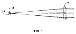
より厳しい整列公差を満足するために、変更された放出光学部及び捕捉光学部の構成が要求される。このような構成は、図3及び図4に表されている。コリメータレンズ18はチルトステージ19に設置されており、より詳細に後述するとともに特許文献1によって開示されるように、コリメータレンズ18が90°の直交軸線に沿ってチルト動作できるようになっている。ビームをコリメータレンズからボイラに直接発射する代わりに、リレーレンズ20がコリメータレンズ18に光学的に連通するように設けられる。リレーレンズは、スロット形成された膜貫通部の軸線に構築される間に整列される。結果として、リレーレンズによって受信されるビームは、リレーレンズの焦点において、スロット形成された貫通部16を通過する必要がある。図4を参照されたい。スロット形成された貫通部をビームが通過する角度は、ビームをコリメータレンズからリレーレンズの異なる位置に誘導することによって、二次元において調整されうる。こうすることによって、ビームが、スロット形成された放出側の貫通部を通って誘導されうるようになり、ボイラの捕捉側のスロット形成された貫通部に達する。ボイラの捕捉側において、捕捉光学部はリレーレンズ20を組込むとともに、コリメータレンズ18を図3及び図4に示されたのと同様にチルト動作させる。捕捉コリメータレンズにおいてチルトステージを採用することによって、最大強度の受信されたコリメートされたビームが、光学的に接続された多重モード型ファイバに伝達されることが保証される。効果的な光学的接続をさらにもたらすために、放出ビームは、従来技術のシステムにおける約20mmとは対照的に直径約5mmにコリメートされる。
In order to satisfy tighter alignment tolerances, modified emission and capture optics configurations are required. Such a configuration is illustrated in FIGS. The
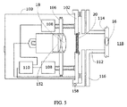
図5は、整列可能な放出光学部及び捕捉光学部の実施形態を概略的に表している。送信器及び受信器はデザインが類似している。送信器は、光ファイバから現れるレーザ光のコリメートされたビームを発生させる。受信器はコリメートされた光のビームを捕捉するとともに、それをファイバ内に集束させる。(この光学システムを介して光を逆方向に送信することもでき、送信器及び受信器の大部分の要素は同一である。)以下の説明は、送信器モジュール及び受信器モジュールのいずれにも当てはまる。 FIG. 5 schematically represents an embodiment of the alignable emission and capture optics. The transmitter and receiver are similar in design. The transmitter generates a collimated beam of laser light that emerges from the optical fiber. The receiver captures the collimated beam of light and focuses it into the fiber. (Light can also be transmitted in the reverse direction through this optical system, and most elements of the transmitter and receiver are the same.) The following description applies to both the transmitter module and the receiver module. apply.
放出光学部及び捕捉光学部は、リレーレンズ20によって閉塞されるオリフィス104が形成された前縁側部102を有するハウジング100内に設置されうる。ハウジングは、放出光学部及び捕捉光学部を周囲環境から保護するためのNEMA-4容器でありうる。図5に示されるように、コリメータレンズ18は運動チルトステージ106に取付けられており、この運動チルトステージ106は、コリメータレンズ18を、放出光学部の光学的軸線に対して直角の直交軸線回りにチップ動作(tip)及びチルト動作(tilt)させるように配置される。2つの直接駆動式ステッピングモータ108によって、このチップ動作及びチルト動作がもたらされる。これらモータは、イーサネット(登録商標)その他類似の接続手段を介してコンピュータによって制御される。この接続は、混信を回避するために光ファイバを通じてなされうる。ステッピングモータ108は、電力供給が絶たれたときにそれらの位置を維持する。そのため、光学的整列作用が停電によって影響を受けなくなる。ステッピングモータは、モータ駆動部110によって駆動される。
The emission optics and capture optics can be installed in a
周期的又は連続的なシステム整列動作の間、制御コンピュータは、伝送されて検出されるレーザ光の量をモニタする。好ましくは別個の整列波長、例えば可視光又は近赤外線が、周期的又は連続的な整列処理のために提供される。いかなる位置ずれによっても検出信号は減少する。自己整列モードにおいて、コンピュータは検出信号を測定するとともに、2つのステッピングモータのうちの一方に命令を出して一方向に少し移動させ、次いで検出信号を再測定する。信号が増大すると、コンピュータはステッピングモータに命令を出して、信号が増大しなくなるまで同一方向に再び移動させる。コンピュータは、次いで他方のステッピングモータに命令を出して、検出信号を最大化するように直交軸線に沿って移動させ、そして他方のセンサヘッドに対して全手順を繰り返す。検出信号が増大するのに従って、検出器の増幅器利得は自動的に減少し、そのため、自己整列作用は、信号サイズが何回か繰返される間にわたって進行する。この自己整列システムは、ナノワット単位からミリワット単位までの検出電力において機能しうる。 During periodic or continuous system alignment operations, the control computer monitors the amount of laser light transmitted and detected. Preferably separate alignment wavelengths, such as visible light or near infrared, are provided for periodic or continuous alignment processing. Any misregistration will reduce the detection signal. In the self-alignment mode, the computer measures the detection signal and commands one of the two stepper motors to move it slightly in one direction, and then re-measures the detection signal. As the signal increases, the computer commands the stepper motor to move again in the same direction until the signal no longer increases. The computer then commands the other stepper motor to move along the orthogonal axis to maximize the detection signal and repeat the entire procedure for the other sensor head. As the detection signal increases, the detector amplifier gain automatically decreases, so that the self-alignment effect proceeds over several iterations of the signal size. This self-aligning system can function at detection powers from nanowatts to milliwatts.
「ヒルクライミング」アルゴリズムは、実質的なノイズが存在する状態で、信号が略全損失された後にシステムを整列させられるとともに、他の整列システムであれば制御用電子機器の限界まで位置ずれを生じさせうるビームの阻害、停電、機械的衝撃その他の障害に耐える。自己整列作用のために要求されるあらゆるものは、所定の位置空間における最大値を有する有限の信号である。特定の導入条件に応じて、自己整列作用は設定された間隔、例えば1時間ごとに周期的に、又は拡張された期間、例えば数日の処理の後に必要に応じて行われる。制御コンピュータは導かれる信号をモニタし、信号が既定の閾値を下回って低下したときのみに自己整列させる。 The “hill climbing” algorithm allows the system to be aligned after substantial loss of signal in the presence of substantial noise, and misaligns to the limit of the control electronics for other alignment systems. Withstands beam blockage, power outages, mechanical shocks and other disturbances Everything required for the self-alignment action is a finite signal with a maximum value in a given position space. Depending on the specific introduction conditions, the self-aligning action is carried out as required after a set interval, for example every hour periodically or after an extended period, for example several days of processing. The control computer monitors the derived signal and only self-aligns when the signal falls below a predetermined threshold.
一実施形態において、観測管112は基端及び末端を有する。基端は、ボイラの外壁114から直角に延在するように取付けられるとともに、長尺の貫通部16が観測管112の内部空間に連通している。フランジ116が観測管112の末端に設けられる。フランジ116によって、ハウジング100が、ボイラのフランジに隣接する前縁端102に取付可能であるとともに、リレーレンズ20が貫通部16に光学的に連通する。この態様において、ビームは、貫通部16を通ってボイラの内部空間118に伝送されるとともに、ボイラを越えて、図5に関連して前述したものと概ね同一の捕捉光学部を備えた受信器へと伝送されうる。
In one embodiment, the
図6は、整列可能な放出光学部及び捕捉光学部の代替的な実施形態200を表している。図6は、同様のデザインからなる送信器及び受信器として記載される。代替的な実施形態200において、レンズ202は光ファイバ204に光学的に接続される。レンズ202は、本明細書において「コリメータ」レンズと称され、(概ね一定の直径からなるビームを生成する)真性のコリメータレンズでありうる。或いは、コリメータレンズ202は、僅かに拡大したビーム206を提供する「準」コリメータレンズのものでもよい。ファイバ204及びレンズ202は、固定された関係により一緒に機械的に連結されるとともに、並進運動機構部210によって、直交するX-Y軸線208に沿って「並進運動」して移動可能である。放出されたビーム206は、並進運動によって、リレーレンズ212の選択部位に当たるように移動可能であり、リレーレンズ212は、ビームを膜のスロットに通して導くとともに、ビームを(捕捉光学部のレンズ202に対応する)受信側光学部又は捕捉光学部の周りに集束させる。図5の実施形態に関連して前述したものと同様のステッピングモータ、コンピュータ制御器及び「ヒルクライミング」アルゴリズムが並進運動機構部210に関連付けられており、概ね連続的な整列補正作用を提供する。
FIG. 6 depicts an
開示内容の種々の実施形態は、各従属項が、独立項と同様に、先行する従属項の各々の限定要素を組入れた多項従属項であるかの如く、特許請求の範囲に記載された種々の要素を組合わせたものをも含みうる。このような組合せが本願の開示内容の範囲内であることは明らかである。 Various embodiments of the disclosure may be found in the claims, as if each dependent claim was a multiple dependent claim incorporating the respective limiting elements of the preceding dependent claim, as well as the independent claim. A combination of these elements may also be included. It is clear that such combinations are within the scope of the present disclosure.
多数の実施形態を参照して、本発明を特定的に図示するとともに説明したものの、当該技術分野に属する当業者は、本明細書に開示される種々の実施形態に対して、本発明の思想及び範囲から逸脱することなくその形態及び細部について変更が可能である点と、本明細書において開示される種々の実施形態によって、特許請求の範囲が限定されることは意図されていない点とを理解するであろう。本明細書において記載されたすべての参考文献は、参照することによりその全体を本明細書に組入れる。 Although the present invention has been particularly shown and described with reference to a number of embodiments, those skilled in the art will appreciate that the various aspects disclosed herein may It should be noted that changes may be made in form and detail without departing from the scope, and that the scope of the claims is not intended to be limited by the various embodiments disclosed herein. You will understand. All references mentioned herein are hereby incorporated by reference in their entirety.
Claims (20)
a)ボイラの両側に在る隣接する蒸気管を再配置することなく、第1の貫通部及び第2の貫通部を前記隣接する蒸気管の間の金属膜に形成し、
b)いずれもボイラの内部空間の外側に位置する放出コリメータレンズと放出リレーレンズとを備える放出光学部を介して、光ビームを投射することを含み、前記放出リレーレンズは、前記光ビームが前記放出リレーレンズの焦点において前記第1の貫通部を通過するように前記第1の貫通部に光学的に接続されており、
さらに、
c)前記ボイラの内部空間の外側に位置する捕捉光学部により前記光ビームを受信することを含み、前記捕捉光学部は、前記第2の貫通部に光学的に接続される捕捉リレーレンズと、該捕捉リレーレンズに光学的に接続される捕捉コリメータレンズとを備え、
さらに、
d)コリメートされた受光ビームの強度を決定し、
e)前記放出コリメータレンズ及び前記捕捉コリメータレンズのうちの少なくとも一方を整列させて、コリメートされた前記受光ビームの強度を最大化することを含む、モニタ方法。 A monitoring method for monitoring combustion characteristics in an internal space of a boiler having a wall portion having a plurality of parallel steam pipes separated by a metal film,
a) without rearranging the adjacent steam pipes on both sides of the boiler, forming the first penetration part and the second penetration part in the metal film between the adjacent steam pipes;
b) Both through the emission optical portion and a release collimator lens and release the relay lens positioned outside the inner space of the boiler, the method comprising projecting light beams, the release relay lens, the light beam is the Optically connected to the first penetration so as to pass through the first penetration at the focal point of the emission relay lens ;
further,
c) receiving the light beam by a capture optic located outside the internal space of the boiler, the capture optic being optically connected to the second penetration; and A capture collimator lens optically connected to the capture relay lens,
further,
d) determine the intensity of the collimated received beam;
e) A method of monitoring comprising aligning at least one of the emitted collimator lens and the capture collimator lens to maximize the intensity of the collimated received beam.
選択レーザ発振周波数を有するダイオードレーザと、
前記ダイオードレーザによって生成されるビームに光学的に接続される放出コリメータレンズと、
放出リレーレンズであって、前記放出コリメータレンズに光学的に接続されていて、前記ビームが隣接する蒸気管の間の第1の金属膜における放出リレーレンズの焦点において第1の貫通部を通過するように構成される放出リレーレンズと、
投射される前記ビームを、前記第1の金属膜とは反対の第2の金属膜における第2の貫通部に通して受信するように構成される、捕捉リレーレンズと、
前記捕捉リレーレンズに光学的に接続される捕捉コリメータレンズと、
前記捕捉コリメータレンズに光学的に接続される光ファイバと、
前記光ファイバに光学的に接続されていて、前記選択レーザ発振周波数に対して感受性を有する検出器と、
前記放出コリメータレンズ及び前記捕捉コリメータレンズのうちの少なくとも一方に関連付けられていて、前記検出器によって受信される光量を最大化させるように前記コリメータレンズを前記ビームに対して整列させる、整列機構部とを備える、検知装置。 A detection device for detecting combustion characteristics of an internal space of a boiler having a plurality of parallel steam pipes separated by a metal film,
A diode laser having a selected lasing frequency;
An emission collimator lens optically connected to the beam produced by the diode laser;
An emission relay lens, optically connected to the emission collimator lens, wherein the beam passes through a first penetration at the focal point of the emission relay lens in a first metal film between adjacent vapor tubes. An emission relay lens configured as:
A capture relay lens configured to receive the projected beam through a second penetration in a second metal film opposite to the first metal film;
A capture collimator lens optically connected to the capture relay lens;
An optical fiber optically connected to the capture collimator lens;
A detector optically connected to the optical fiber and sensitive to the selected lasing frequency;
An alignment mechanism associated with at least one of the emission collimator lens and the capture collimator lens to align the collimator lens with respect to the beam so as to maximize the amount of light received by the detector; A detection device comprising:
Applications Claiming Priority (5)
| Application Number | Priority Date | Filing Date | Title |
|---|---|---|---|
| US14373209P | 2009-01-09 | 2009-01-09 | |
| US61/143,732 | 2009-01-09 | ||
| US14438409P | 2009-01-13 | 2009-01-13 | |
| US61/144,384 | 2009-01-13 | ||
| PCT/US2010/020345 WO2010080892A2 (en) | 2009-01-09 | 2010-01-07 | Method and apparatus for monitoring combustion properties in an interior of a boiler |
Publications (3)
| Publication Number | Publication Date |
|---|---|
| JP2012514755A JP2012514755A (en) | 2012-06-28 |
| JP2012514755A5 JP2012514755A5 (en) | 2012-12-27 |
| JP5576399B2 true JP5576399B2 (en) | 2014-08-20 |
Family
ID=42317130
Family Applications (1)
| Application Number | Title | Priority Date | Filing Date |
|---|---|---|---|
| JP2011545421A Active JP5576399B2 (en) | 2009-01-09 | 2010-01-07 | MONITORING METHOD AND MONITORING DEVICE FOR MONITORING COMBUSTION CHARACTERISTICS IN BOILER INTERNAL SPACE |
Country Status (11)
| Country | Link |
|---|---|
| US (1) | US8786856B2 (en) |
| EP (1) | EP2376840B1 (en) |
| JP (1) | JP5576399B2 (en) |
| KR (1) | KR101674694B1 (en) |
| CN (1) | CN102308150B (en) |
| AU (1) | AU2010203674B2 (en) |
| CA (1) | CA2748793C (en) |
| DK (1) | DK2376840T3 (en) |
| ES (1) | ES2704840T3 (en) |
| PL (1) | PL2376840T3 (en) |
| WO (1) | WO2010080892A2 (en) |
Families Citing this family (7)
| Publication number | Priority date | Publication date | Assignee | Title |
|---|---|---|---|---|
| EP2839265B1 (en) * | 2012-04-19 | 2017-07-26 | Zolo Technologies, Inc. | In-furnace retro-reflectors with steerable tunable diode laser absorption spectrometer |
| CA2934271C (en) * | 2013-12-20 | 2022-05-31 | Zolo Technologies, Inc. | Method and apparatus for monitoring port blockage for tdlas measurements in harsh environments |
| CN105444201B (en) | 2014-09-26 | 2018-11-13 | 通用电气公司 | The method and its system of burning optimization |
| CN104390802A (en) * | 2014-11-22 | 2015-03-04 | 山东省特种设备检验研究院 | Pressure-bearing equipment detection method and special pressure-bearing equipment detection device thereof |
| CN106017725B (en) * | 2016-05-26 | 2019-07-09 | 中国人民解放军战略支援部队航天工程大学 | A kind of measuring device suitable for Combustion Flow Field gas 2-d reconstruction |
| CN107703098A (en) * | 2017-10-12 | 2018-02-16 | 中国能源建设集团科技发展有限公司 | Boiler furnace nitrogen oxides measurement apparatus |
| DE102021121860A1 (en) * | 2021-08-24 | 2023-03-02 | Vaillant Gmbh | Method for inspecting and monitoring a heating device using a sensor-generated image |
Family Cites Families (101)
| Publication number | Priority date | Publication date | Assignee | Title |
|---|---|---|---|---|
| US2841122A (en) * | 1953-03-12 | 1958-07-01 | Babcock & Wilcox Co | Wall tube fluid heater with a releasably anchored enclosure |
| US3754533A (en) * | 1971-11-24 | 1973-08-28 | Babcock & Wilcox Ltd | Tube support system |
| US4037113A (en) | 1975-04-11 | 1977-07-19 | Forney Engineering Company | Flame detector |
| US4028081A (en) | 1975-12-11 | 1977-06-07 | Bell Telephone Laboratories, Incorporated | Method for manufacturing helical optical fiber |
| US4011403A (en) | 1976-03-30 | 1977-03-08 | Northwestern University | Fiber optic laser illuminators |
| US4305640A (en) | 1978-11-24 | 1981-12-15 | National Research Development Corporation | Laser beam annealing diffuser |
| US4360372A (en) | 1980-11-10 | 1982-11-23 | Northern Telecom Limited | Fiber optic element for reducing speckle noise |
| US4432286A (en) | 1982-05-19 | 1984-02-21 | The United States Of America As Represented By The United States Department Of Energy | Combustion pinhole camera system |
| DD219059A3 (en) * | 1982-09-14 | 1985-02-20 | Freiberg Brennstoffinst | PERISKOP FOR HIGH-TEMPERATURE REACTORS |
| US4672198A (en) | 1986-01-24 | 1987-06-09 | At&T Company And At&T Bell Laboratories | Signal sampler microbending fiber test clip |
| JPS63133035A (en) * | 1986-11-26 | 1988-06-04 | Anritsu Corp | Light transmission characteristic tester |
| US4741586A (en) | 1987-02-20 | 1988-05-03 | The Board Of Trustees Of The Leland Stanford Junior University | Dynamic coupler using two-mode optical waveguides |
| US4915468A (en) | 1987-02-20 | 1990-04-10 | The Board Of Trustees Of The Leland Stanford Junior University | Apparatus using two-mode optical waveguide with non-circular core |
| US4989979A (en) | 1989-01-17 | 1991-02-05 | Board Of Regents, The University Of Texas System | Optical fiber sensors with full common-mode compensation and measurand sensitivity enhancement |
| DK0435825T3 (en) | 1989-12-27 | 1996-02-12 | Ciba Geigy Ag | Apparatus for homogenizing the inhomogeneous light distribution in a laser beam light beam |
| US5042905A (en) | 1990-06-15 | 1991-08-27 | Honeywell Inc. | Electrically passive fiber optic position sensor |
| IT1251246B (en) | 1991-08-27 | 1995-05-05 | Sie Systems Spa | DEVICE FOR DETECTION OF THE PRESENCE AND QUALITY OF THE FLAME THROUGH THE COLLECTION AND ANALYSIS OF ELECTROMAGNETIC RADIATIONS OF DIFFERENT WAVELENGTH |
| US5291013A (en) | 1991-12-06 | 1994-03-01 | Alamed Corporation | Fiber optical monitor for detecting normal breathing and heartbeat motion based on changes in speckle patterns |
| US5436444A (en) | 1991-12-06 | 1995-07-25 | Alamed Corporation | Multimode optical fiber motion monitor with audible output |
| FI90469C (en) * | 1992-02-25 | 1994-02-10 | Imatran Voima Oy | Arrangement in a hearth camera |
| US5468239A (en) | 1992-04-13 | 1995-11-21 | Sorenson Laboratories, Inc. | Apparatus and methods for using a circumferential light-emitting surgical laser probe |
| WO1993022706A1 (en) | 1992-04-28 | 1993-11-11 | The Furukawa Electric Co., Ltd. | External modulator for optical communication |
| US5298047A (en) | 1992-08-03 | 1994-03-29 | At&T Bell Laboratories | Method of making a fiber having low polarization mode dispersion due to a permanent spin |
| US5798840A (en) | 1992-08-05 | 1998-08-25 | The Aerospace Corporation | Fast optical absorption tomography apparatus and method |
| GB9217705D0 (en) | 1992-08-20 | 1992-09-30 | Ici Plc | Data-recordal using laser beams |
| WO1994011708A1 (en) | 1992-11-06 | 1994-05-26 | Martin Marietta Corporation | Interferometric optical sensor read-out system |
| US5408554A (en) | 1993-12-17 | 1995-04-18 | Porta System Corporation | Fiber optic coupling |
| US5448071A (en) | 1993-04-16 | 1995-09-05 | Bruce W. McCaul | Gas spectroscopy |
| JPH06331543A (en) * | 1993-05-24 | 1994-12-02 | Fuji Electric Co Ltd | Floating-particle-concentration measuring apparatus |
| US5396506A (en) | 1993-12-09 | 1995-03-07 | United Technologies Corporation | Coupled multiple output fiber laser |
| DE4446425A1 (en) | 1994-12-23 | 1996-06-27 | Siemens Ag | Method and arrangement for measuring a magnetic field using the Faraday effect with compensation for changes in intensity and temperature |
| CN1163665A (en) | 1994-12-23 | 1997-10-29 | 西门子公司 | Process and arrangement for measuring magnetic field-using faraday effect with compensations in intensity and temperature effects |
| DE19503929A1 (en) | 1995-02-07 | 1996-08-08 | Ldt Gmbh & Co | Color imaging systems |
| US5598264A (en) | 1995-05-18 | 1997-01-28 | Failes; Michael | Noise compensated interferometric measuring device and method using signal and reference interferometers |
| JPH0915447A (en) * | 1995-06-30 | 1997-01-17 | Oki Electric Ind Co Ltd | Structure and method for fixing optical fiber collimator |
| US5621213A (en) | 1995-07-07 | 1997-04-15 | Novitron International Inc. | System and method for monitoring a stack gas |
| JP3860237B2 (en) | 1995-07-26 | 2006-12-20 | 富士通株式会社 | Optical fiber having polarization dispersion suppression characteristic and manufacturing method thereof |
| WO1997007067A1 (en) | 1995-08-16 | 1997-02-27 | Plasma Optical Fibre B.V. | Optical fiber with low polarisation mode dispersion |
| JPH0973020A (en) | 1995-09-05 | 1997-03-18 | Toshiba Corp | Optical multiplexer/demultiplexer |
| EP0766080A1 (en) | 1995-09-29 | 1997-04-02 | FINMECCANICA S.p.A. AZIENDA ANSALDO | System and method for monitoring combustion and pollutants by means of laser diodes |
| JPH09152126A (en) * | 1995-11-30 | 1997-06-10 | Tokyo Gas Co Ltd | Flame sensing device |
| US5742715A (en) | 1995-12-21 | 1998-04-21 | Lucent Technologies Inc. | Optical fiber status analyzer and related methods |
| GB2309317A (en) | 1996-01-17 | 1997-07-23 | Univ Southampton | Optical fibre device |
| US5732166A (en) | 1996-03-11 | 1998-03-24 | Hamann; Oliver | High temperature-resistant optical sensing apparatus and method of making |
| AU4379197A (en) | 1996-08-16 | 1998-03-06 | Novartis Ag | Optical detector |
| US6169830B1 (en) | 1996-08-26 | 2001-01-02 | Arroyo Optics, Inc. | Methods of fabricating grating assisted coupler devices |
| US5805318A (en) | 1996-11-04 | 1998-09-08 | Honeywell Inc. | Apparatus for determining the effect of modal noise on a communication system by flexing an optical fiber |
| US5841915A (en) | 1996-11-04 | 1998-11-24 | Honeywell Inc. | Apparatus for determining the effect of modal noise on a communication system by affecting an optical fiber discontinuity |
| GB2320155B (en) | 1996-12-03 | 2000-11-01 | Chelsea Instr Ltd | Method and apparatus for the imaging of gases |
| US6046809A (en) | 1998-02-04 | 2000-04-04 | S3 Incorporated | Real-time in situ multiple gas species sensing method |
| JPH113534A (en) * | 1997-04-14 | 1999-01-06 | Toray Ind Inc | Optical recorder and optical recording medium |
| JPH10301153A (en) | 1997-04-23 | 1998-11-13 | Sony Corp | Light source device and optical measuring instrument and exposure device using it |
| US6124597A (en) | 1997-07-07 | 2000-09-26 | Cedars-Sinai Medical Center | Method and devices for laser induced fluorescence attenuation spectroscopy |
| US6016372A (en) | 1997-10-16 | 2000-01-18 | World Precision Instruments, Inc. | Chemical sensing techniques employing liquid-core optical fibers |
| US5930029A (en) | 1997-12-02 | 1999-07-27 | Sdl, Inc. | Optical fiber amplifier with optimized power conversion |
| US5960129A (en) | 1997-12-22 | 1999-09-28 | Bayer Corporation | Method and apparatus for detecting liquid and gas segment flow through a tube |
| DE69942446D1 (en) | 1998-03-04 | 2010-07-15 | Jds Uniphase Corp | OPTICAL COUPLERS FOR MULTIMODE FIBERS |
| US6064417A (en) | 1998-03-31 | 2000-05-16 | Eastman Kodak Company | Laser printer using multiple sets of lasers with multiple wavelengths |
| EP0988521A1 (en) | 1998-04-14 | 2000-03-29 | Instrumentarium Corporation | Sensor assembly and method for measuring nitrogen dioxide |
| JP4038631B2 (en) * | 1998-08-28 | 2008-01-30 | 株式会社堀場製作所 | High-speed measurement method and system for temperature, concentration, and chemical species using semiconductor laser spectroscopy |
| US6160255A (en) | 1998-10-05 | 2000-12-12 | The United States Of America As Represented By The Secretary Of The Army | Laser-based photoacoustic sensor and method for trace detection and differentiantion of atmospheric NO and NO2 |
| JP2000121558A (en) * | 1998-10-16 | 2000-04-28 | Mitsubishi Heavy Ind Ltd | Measuring device |
| DE19847832C1 (en) * | 1998-10-16 | 1999-11-04 | Siemens Ag | Optical system operation method for supervision of flame of combustion chamber |
| US6593573B1 (en) | 1998-11-11 | 2003-07-15 | The University Of Manchester Institute Of Science And Technology | Chemical species distribution and mixture monitoring |
| US6510265B1 (en) | 1999-04-21 | 2003-01-21 | Lucent Technologies Inc. | High-speed multi mode fiber optic link |
| US6042365A (en) * | 1999-06-28 | 2000-03-28 | Chen; Yaosheng | Fuel combustion monitoring apparatus and method |
| US6396056B1 (en) | 1999-07-08 | 2002-05-28 | Air Instruments And Measurements, Inc. | Gas detectors and gas analyzers utilizing spectral absorption |
| US6304692B1 (en) | 1999-09-03 | 2001-10-16 | Zolo Technologies, Inc. | Echelle grating dense wavelength division multiplexer/demultiplexer with two dimensional single channel array |
| US6351587B1 (en) | 1999-11-12 | 2002-02-26 | Lucent Technologies Inc. | Multi-fiber digital delay line |
| US6422043B1 (en) | 1999-11-16 | 2002-07-23 | Fitel Usa Corp. | Method of making an improved multimode optical fiber and fiber made by method |
| JP2004500197A (en) | 2000-02-08 | 2004-01-08 | コーネル リサーチ ファンデーション インコーポレーテッド | Multiphoton excitation for fluorescence spectroscopy through optical fibers |
| US6363190B1 (en) | 2000-02-11 | 2002-03-26 | New Focus, Inc. | Polarization insensitive fused fiber coupler method and apparatus |
| US20020031737A1 (en) | 2000-03-10 | 2002-03-14 | American Air Liquide, Inc. | Method for continuously monitoring chemical species and temperature in hot process gases |
| KR100353442B1 (en) | 2000-03-22 | 2002-09-19 | 삼성전자 주식회사 | Structure of multimode optical fiber with reduced scattering loss |
| US6455851B1 (en) | 2000-03-28 | 2002-09-24 | Air Instruments And Measurement, Inc. | Spectroscopic remote sensing exhaust emission monitoring system |
| US6385372B1 (en) | 2000-04-19 | 2002-05-07 | Tera Fiberoptics, Inc. | Fiber optical coupler fabrication and system |
| CN1195202C (en) | 2000-09-15 | 2005-03-30 | 饶云江 | Integrated optical fibre strain and temp sensor device |
| US6519385B1 (en) | 2000-09-27 | 2003-02-11 | The Boeing Company | Method and apparatus for controllably positioning an optical fiber to introduce a phase shift |
| US6959129B2 (en) * | 2000-12-22 | 2005-10-25 | Metrophotonics Inc. | Bidirectional multiplexer and demultiplexer based on a single echelle waveguide grating |
| US20020158202A1 (en) | 2001-01-08 | 2002-10-31 | Webber Michael E. | Laser-based sensor for measuring combustion parameters |
| US6701753B2 (en) | 2001-02-11 | 2004-03-09 | Fitel Usa Corp. | Method and apparatus for making improved optical fiber preforms and optical fiber therefrom |
| US6766070B2 (en) | 2001-04-27 | 2004-07-20 | The United States Of America As Represented By The Secretary Of The Navy | High power fiber optic modulator system and method |
| JP2003004633A (en) | 2001-06-22 | 2003-01-08 | Nissan Motor Co Ltd | Apparatus for measuring fuel concentration of engine |
| US6950452B2 (en) | 2001-09-28 | 2005-09-27 | The Furukawa Electric Co., Ltd. | Semiconductor laser module and method for simultaneously reducing relative intensity noise (RIN) and stimulated brillouin scattering (SBS) |
| KR100417000B1 (en) | 2001-12-03 | 2004-02-05 | 삼성전자주식회사 | Apparatus for low polarization mode dispersion |
| JP2004096088A (en) | 2002-07-10 | 2004-03-25 | Fuji Photo Film Co Ltd | Multiplex laser light source and aligner |
| WO2004050573A1 (en) | 2002-09-25 | 2004-06-17 | Giacomo Stefano Roba | Process for producing an optical fiber having a low polarization mode dispersion |
| JP2004117236A (en) * | 2002-09-27 | 2004-04-15 | Fuji Photo Film Co Ltd | Optical characteristic measuring device |
| AU2003291003C1 (en) | 2002-11-18 | 2009-05-21 | Virginia Tech Intellectual Properties, Inc. | System, device, and method for detecting perturbations |
| KR100469736B1 (en) | 2002-11-21 | 2005-02-02 | 삼성전자주식회사 | Wavelength locked fabry perot laser device with multi wavelength lasing source and optical transmitter using the same |
| US20040160596A1 (en) | 2003-02-19 | 2004-08-19 | Pactonix, Inc. | Apparatus and method to accurately monitor signal quality in optical signal transmission systems |
| WO2004090496A2 (en) | 2003-03-31 | 2004-10-21 | Zolo Technologies, Inc. | Method and apparatus for the monitoring and control of combustion |
| JP2004354671A (en) | 2003-05-29 | 2004-12-16 | Nikon Corp | Speckle pattern dispersing device and laser light irradiation apparatus |
| ATE429657T1 (en) | 2003-12-30 | 2009-05-15 | Prysmian Spa | LOW POLARIZATION MODE DISPERSION (PMD) OPTICAL FIBER CONNECTION AND PRODUCTION METHOD THEREOF |
| US7158552B2 (en) | 2004-02-13 | 2007-01-02 | Lucent Technologies Inc. | Low relative intensity noise fiber grating type laser diode |
| US7787728B2 (en) | 2004-03-31 | 2010-08-31 | Zolo Technologies, Inc. | Optical mode noise averaging device |
| US7724413B2 (en) | 2005-07-11 | 2010-05-25 | Mitsubishi Electric Corporation | Speckle removing light source and lighting apparatus |
| US8544279B2 (en) * | 2005-11-04 | 2013-10-01 | Zolo Technologies, Inc. | Method and apparatus for spectroscopic measurements in the combustion zone of a gas turbine engine |
| JP4446195B2 (en) * | 2005-12-19 | 2010-04-07 | 富士電機ホールディングス株式会社 | Laser beam output unit, laser beam input unit and laser gas analyzer |
| JP2011158384A (en) | 2010-02-02 | 2011-08-18 | Seiko Epson Corp | Particulate detector |
| CN101988845B (en) | 2010-07-30 | 2012-04-18 | 西安理工大学 | Device and method for detecting fused silica liquid level by laser curved mirror reflection |
-
2010
- 2010-01-07 PL PL10729501T patent/PL2376840T3/en unknown
- 2010-01-07 JP JP2011545421A patent/JP5576399B2/en active Active
- 2010-01-07 KR KR1020117015677A patent/KR101674694B1/en active IP Right Grant
- 2010-01-07 CN CN201080006508.2A patent/CN102308150B/en active Active
- 2010-01-07 ES ES10729501T patent/ES2704840T3/en active Active
- 2010-01-07 WO PCT/US2010/020345 patent/WO2010080892A2/en active Application Filing
- 2010-01-07 US US13/142,791 patent/US8786856B2/en active Active
- 2010-01-07 CA CA2748793A patent/CA2748793C/en active Active
- 2010-01-07 AU AU2010203674A patent/AU2010203674B2/en active Active
- 2010-01-07 EP EP10729501.6A patent/EP2376840B1/en active Active
- 2010-01-07 DK DK10729501.6T patent/DK2376840T3/en active
Also Published As
| Publication number | Publication date |
|---|---|
| JP2012514755A (en) | 2012-06-28 |
| PL2376840T3 (en) | 2019-04-30 |
| CA2748793A1 (en) | 2010-07-15 |
| WO2010080892A2 (en) | 2010-07-15 |
| EP2376840B1 (en) | 2018-10-31 |
| ES2704840T3 (en) | 2019-03-20 |
| DK2376840T3 (en) | 2019-02-04 |
| US8786856B2 (en) | 2014-07-22 |
| CN102308150A (en) | 2012-01-04 |
| AU2010203674B2 (en) | 2014-09-25 |
| KR20110120863A (en) | 2011-11-04 |
| EP2376840A4 (en) | 2013-12-25 |
| EP2376840A2 (en) | 2011-10-19 |
| US20110300492A1 (en) | 2011-12-08 |
| CA2748793C (en) | 2016-06-07 |
| WO2010080892A3 (en) | 2010-09-02 |
| KR101674694B1 (en) | 2016-11-09 |
| AU2010203674A1 (en) | 2011-07-28 |
| CN102308150B (en) | 2014-01-01 |
| AU2010203674A2 (en) | 2012-01-19 |
Similar Documents
| Publication | Publication Date | Title |
|---|---|---|
| JP5576399B2 (en) | MONITORING METHOD AND MONITORING DEVICE FOR MONITORING COMBUSTION CHARACTERISTICS IN BOILER INTERNAL SPACE | |
| KR101072657B1 (en) | Method and apparatus for the monitoring and control of combustion | |
| KR101994509B1 (en) | In-Furnace Retro-Reflectors with Steerable Tunable Diode Laser Absorption Spectrometer | |
| CN102809427A (en) | Auto-aligning spectroscopy system | |
| US10948184B2 (en) | Method and apparatus for monitoring port blockage for TDLAS measurements in harsh environments | |
| JP2012514755A5 (en) | ||
| CN102589699B (en) | Straightening and aligning system and method used for combustion detection system | |
| CN202433092U (en) | Alignment system for combustion detection system |
Legal Events
| Date | Code | Title | Description |
|---|---|---|---|
| A521 | Request for written amendment filed |
Free format text: JAPANESE INTERMEDIATE CODE: A523 Effective date: 20121106 |
|
| A621 | Written request for application examination |
Free format text: JAPANESE INTERMEDIATE CODE: A621 Effective date: 20121106 |
|
| A977 | Report on retrieval |
Free format text: JAPANESE INTERMEDIATE CODE: A971007 Effective date: 20130925 |
|
| A131 | Notification of reasons for refusal |
Free format text: JAPANESE INTERMEDIATE CODE: A131 Effective date: 20131001 |
|
| A601 | Written request for extension of time |
Free format text: JAPANESE INTERMEDIATE CODE: A601 Effective date: 20131227 |
|
| A602 | Written permission of extension of time |
Free format text: JAPANESE INTERMEDIATE CODE: A602 Effective date: 20140110 |
|
| A521 | Request for written amendment filed |
Free format text: JAPANESE INTERMEDIATE CODE: A523 Effective date: 20140131 |
|
| TRDD | Decision of grant or rejection written | ||
| A01 | Written decision to grant a patent or to grant a registration (utility model) |
Free format text: JAPANESE INTERMEDIATE CODE: A01 Effective date: 20140603 |
|
| A61 | First payment of annual fees (during grant procedure) |
Free format text: JAPANESE INTERMEDIATE CODE: A61 Effective date: 20140703 |
|
| R150 | Certificate of patent or registration of utility model |
Ref document number: 5576399 Country of ref document: JP Free format text: JAPANESE INTERMEDIATE CODE: R150 |
|
| R250 | Receipt of annual fees |
Free format text: JAPANESE INTERMEDIATE CODE: R250 |
|
| R250 | Receipt of annual fees |
Free format text: JAPANESE INTERMEDIATE CODE: R250 |
|
| S111 | Request for change of ownership or part of ownership |
Free format text: JAPANESE INTERMEDIATE CODE: R313113 |
|
| R350 | Written notification of registration of transfer |
Free format text: JAPANESE INTERMEDIATE CODE: R350 |
|
| R250 | Receipt of annual fees |
Free format text: JAPANESE INTERMEDIATE CODE: R250 |
|
| R250 | Receipt of annual fees |
Free format text: JAPANESE INTERMEDIATE CODE: R250 |
|
| R250 | Receipt of annual fees |
Free format text: JAPANESE INTERMEDIATE CODE: R250 |