JP5570570B2 - Wireless power transmitter - Google Patents
Wireless power transmitter Download PDFInfo
- Publication number
- JP5570570B2 JP5570570B2 JP2012224755A JP2012224755A JP5570570B2 JP 5570570 B2 JP5570570 B2 JP 5570570B2 JP 2012224755 A JP2012224755 A JP 2012224755A JP 2012224755 A JP2012224755 A JP 2012224755A JP 5570570 B2 JP5570570 B2 JP 5570570B2
- Authority
- JP
- Japan
- Prior art keywords
- cell group
- cell
- wireless power
- cells
- power transmission
- Prior art date
- Legal status (The legal status is an assumption and is not a legal conclusion. Google has not performed a legal analysis and makes no representation as to the accuracy of the status listed.)
- Expired - Fee Related
Links
- 230000005540 biological transmission Effects 0.000 claims description 46
- 239000003990 capacitor Substances 0.000 claims description 12
- RYGMFSIKBFXOCR-UHFFFAOYSA-N Copper Chemical group [Cu] RYGMFSIKBFXOCR-UHFFFAOYSA-N 0.000 claims description 3
- 229910052802 copper Inorganic materials 0.000 claims description 3
- 239000010949 copper Substances 0.000 claims description 3
- 239000004020 conductor Substances 0.000 claims description 2
- 229910052724 xenon Inorganic materials 0.000 claims 1
- FHNFHKCVQCLJFQ-UHFFFAOYSA-N xenon atom Chemical compound [Xe] FHNFHKCVQCLJFQ-UHFFFAOYSA-N 0.000 claims 1
- 238000000034 method Methods 0.000 description 7
- 230000005674 electromagnetic induction Effects 0.000 description 6
- 238000009499 grossing Methods 0.000 description 4
- 230000015572 biosynthetic process Effects 0.000 description 3
- 238000005516 engineering process Methods 0.000 description 3
- 230000004907 flux Effects 0.000 description 2
- 230000006698 induction Effects 0.000 description 2
- 230000002411 adverse Effects 0.000 description 1
- 239000012141 concentrate Substances 0.000 description 1
- 230000001627 detrimental effect Effects 0.000 description 1
- 238000010586 diagram Methods 0.000 description 1
- 230000000694 effects Effects 0.000 description 1
Images


Classifications
-
- H—ELECTRICITY
- H02—GENERATION; CONVERSION OR DISTRIBUTION OF ELECTRIC POWER
- H02J—CIRCUIT ARRANGEMENTS OR SYSTEMS FOR SUPPLYING OR DISTRIBUTING ELECTRIC POWER; SYSTEMS FOR STORING ELECTRIC ENERGY
- H02J50/00—Circuit arrangements or systems for wireless supply or distribution of electric power
- H02J50/40—Circuit arrangements or systems for wireless supply or distribution of electric power using two or more transmitting or receiving devices
-
- H—ELECTRICITY
- H02—GENERATION; CONVERSION OR DISTRIBUTION OF ELECTRIC POWER
- H02J—CIRCUIT ARRANGEMENTS OR SYSTEMS FOR SUPPLYING OR DISTRIBUTING ELECTRIC POWER; SYSTEMS FOR STORING ELECTRIC ENERGY
- H02J50/00—Circuit arrangements or systems for wireless supply or distribution of electric power
- H02J50/10—Circuit arrangements or systems for wireless supply or distribution of electric power using inductive coupling
- H02J50/12—Circuit arrangements or systems for wireless supply or distribution of electric power using inductive coupling of the resonant type
-
- H—ELECTRICITY
- H02—GENERATION; CONVERSION OR DISTRIBUTION OF ELECTRIC POWER
- H02J—CIRCUIT ARRANGEMENTS OR SYSTEMS FOR SUPPLYING OR DISTRIBUTING ELECTRIC POWER; SYSTEMS FOR STORING ELECTRIC ENERGY
- H02J50/00—Circuit arrangements or systems for wireless supply or distribution of electric power
- H02J50/005—Mechanical details of housing or structure aiming to accommodate the power transfer means, e.g. mechanical integration of coils, antennas or transducers into emitting or receiving devices
-
- H—ELECTRICITY
- H02—GENERATION; CONVERSION OR DISTRIBUTION OF ELECTRIC POWER
- H02J—CIRCUIT ARRANGEMENTS OR SYSTEMS FOR SUPPLYING OR DISTRIBUTING ELECTRIC POWER; SYSTEMS FOR STORING ELECTRIC ENERGY
- H02J50/00—Circuit arrangements or systems for wireless supply or distribution of electric power
- H02J50/40—Circuit arrangements or systems for wireless supply or distribution of electric power using two or more transmitting or receiving devices
- H02J50/402—Circuit arrangements or systems for wireless supply or distribution of electric power using two or more transmitting or receiving devices the two or more transmitting or the two or more receiving devices being integrated in the same unit, e.g. power mats with several coils or antennas with several sub-antennas
-
- H—ELECTRICITY
- H04—ELECTRIC COMMUNICATION TECHNIQUE
- H04B—TRANSMISSION
- H04B5/00—Near-field transmission systems, e.g. inductive loop type
-
- H04B5/24—
-
- H04B5/79—
-
- H—ELECTRICITY
- H01—ELECTRIC ELEMENTS
- H01F—MAGNETS; INDUCTANCES; TRANSFORMERS; SELECTION OF MATERIALS FOR THEIR MAGNETIC PROPERTIES
- H01F38/00—Adaptations of transformers or inductances for specific applications or functions
- H01F38/14—Inductive couplings
-
- H—ELECTRICITY
- H02—GENERATION; CONVERSION OR DISTRIBUTION OF ELECTRIC POWER
- H02J—CIRCUIT ARRANGEMENTS OR SYSTEMS FOR SUPPLYING OR DISTRIBUTING ELECTRIC POWER; SYSTEMS FOR STORING ELECTRIC ENERGY
- H02J7/00—Circuit arrangements for charging or depolarising batteries or for supplying loads from batteries
Description
本発明は無線電力送信装置に関し、より詳しくは、無線電力受信装置との電力転送効率を増加させ、外部に漏出される磁場の量を減少させることができる無線電力送信装置に関する。 The present invention relates to a wireless power transmission device, and more particularly to a wireless power transmission device capable of increasing the power transfer efficiency with a wireless power reception device and reducing the amount of magnetic field leaked to the outside.
無線で電気エネルギーを所望の機器に伝達する無線電力転送技術は、既に1800年代に電磁気誘導原理を用いた電気モータや変圧器が使われ始めて、その後にはラジオ波やレーザーのような電磁波を放射して電気エネルギーを転送する方法も試みられた。私達がしばしば使用する電動歯ブラシや一部無線カミソリも実際は電磁気誘導原理により充電される。現在まで無線方式によるエネルギー伝達方式は、磁気誘導、共振、及び短波長無線周波数を用いた遠距離送信技術などがある。 Wireless power transfer technology that wirelessly transmits electrical energy to the desired device has already begun to use electric motors and transformers using the electromagnetic induction principle in the 1800s, and then radiates electromagnetic waves such as radio waves and lasers. Attempts have also been made to transfer electrical energy. Electric toothbrushes and some wireless razors that we often use are actually charged by the electromagnetic induction principle. To date, wireless energy transfer methods include magnetic induction, resonance, and long-distance transmission technology using short-wavelength radio frequencies.
最近にはこのような無線電力転送技術のうち、共振を用いたエネルギー伝達方式がたくさん使われている。 Recently, among such wireless power transfer technologies, many energy transfer methods using resonance have been used.
共振を用いた無線電力転送システムは、無線電力送信装置と無線電力受信装置との間に形成された電気信号がコイルを通じて無線で伝えられるため、使用者は携帯用機器のような電子機器を難無く充電することができる。 In a wireless power transfer system using resonance, an electric signal formed between a wireless power transmitting device and a wireless power receiving device is transmitted wirelessly through a coil, so that a user can easily use an electronic device such as a portable device. Can be charged.
しかしながら、共振を用いたエネルギー伝達方式は、送信側で発生する磁場が外部に漏出される現象が発生することがある。漏出された磁場は人体に露出されて健康に有害な影響を及ぼすことがある。 However, in the energy transfer method using resonance, a phenomenon that a magnetic field generated on the transmission side leaks to the outside may occur. Leaked magnetic fields can be exposed to the human body and have a detrimental effect on health.
本発明の目的は、共振による電力転送がなされる過程における無線電力送信装置と無線電力受信装置との間に発生する磁場の外部への漏出を最小化し、電力転送の効率性が極大化できる無線電力送信装置を提供することにある。 It is an object of the present invention to minimize leakage of a magnetic field generated between a wireless power transmitting apparatus and a wireless power receiving apparatus in a process in which power transfer is performed by resonance, and to maximize power transfer efficiency. It is to provide a power transmission device.
本発明の実施形態に従う無線電力送信装置は、受信装置と共振するよう構成されたコイル及びキャパシタを含み、上記コイルは複数のセルグループ及び上記複数のセルグループを連結するコアを含み、上記複数のセルグループの各々は複数のセルを含み、各セルグループの複数のセルは上記複数のセルに流れる電流により発生する磁場が同一な方向に形成されるように構成され、各セルグループは1つ以上の隣接したセルグループを有し、上記各セルグループ及び上記コアは1つの導線からなることを特徴とする。 A wireless power transmission device according to an embodiment of the present invention includes a coil and a capacitor configured to resonate with a reception device, the coil including a plurality of cell groups and a core connecting the plurality of cell groups, Each of the cell groups includes a plurality of cells, and each of the plurality of cells in each cell group is configured such that a magnetic field generated by a current flowing through the plurality of cells is formed in the same direction. And each of the cell groups and the core are formed of one conductive wire.
本発明の実施形態によれば、次のような効果がある。 The embodiment of the present invention has the following effects.
第1に、無線電力送信装置のコイル構造を改善して磁場の外部への漏出を最小化することができる。 First, the coil structure of the wireless power transmission device can be improved to minimize leakage of the magnetic field to the outside.
第2に、無線電力送信装置と無線電力受信装置との間の電力転送効率を極大化することができる。 Second, the power transfer efficiency between the wireless power transmission device and the wireless power reception device can be maximized.
本明細書及び請求範囲に使われた用語や単語は通常的または辞典的な意味に限定して解釈されてはならず、発明者は自分の発明を最も最善の方法により説明するために用語の概念を適切に定義することができるという原則に立脚して本発明の技術的思想に符合する意味と概念として解釈されなければならない。 Terms and words used in this specification and claims should not be construed as limited to ordinary or lexical meaning, and the inventor should use the terminology to describe his invention in the best possible manner. Based on the principle that the concept can be appropriately defined, it should be interpreted as a meaning and concept consistent with the technical idea of the present invention.
したがって、本明細書に記載された実施形態と図面に図示された構成は、本発明の最も好ましい一実施形態に過ぎないものであり、本実施形態の技術的思想を全て代弁するものではないので、本出願時点でこれらを代えることができる多様な均等物と変形例がありえることを理解すべきである。 Therefore, the embodiment described in the present specification and the configuration illustrated in the drawings are only the most preferable embodiment of the present invention, and do not represent all the technical ideas of the present embodiment. It should be understood that there are various equivalents and variations that can be substituted at the time of this application.
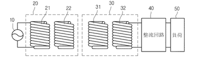
図1は、本発明の一実施形態に従う無線電力転送システムを示す。 FIG. 1 shows a wireless power transfer system according to an embodiment of the present invention.
電力ソース10で生成された電力は送信部20に伝えられ、共振現象により送信部20と共振をなす、即ち、共振周波数値が同一な受信部30に伝えられる。受信部30に伝えられた電力は整流回路40を経て負荷50に伝えられる。負荷50は充電池またはその他の電力を必要とする任意の装置でありうる。
The power generated by the
より具体的に説明すると、電力ソース10は所定周波数の交流電力を提供する交流電力ソースである。
More specifically, the
送信部20は、送信コイル21と送信用共振コイル22とから構成される。送信コイル21は電力ソース10と連結され、交流電流が流れる。送信コイル21に交流電流が流れれば、電磁気誘導により物理的に離隔されている送信用共振コイル22にも交流電流が誘導される。送信用共振コイル22に伝えられた電力は共振により送信部20と共振回路をなす受信部30に伝えられる。
The
インピーダンスがマッチングされた2つのLC回路の間は共振により電力が転送できる。このような共振による電力転送は電磁気誘導による電力転送より遠い距離までより高い効率で電力伝達可能にする。 Power can be transferred by resonance between two LC circuits whose impedances are matched. The power transfer by resonance makes it possible to transfer power with higher efficiency to a far distance than the power transfer by electromagnetic induction.
受信部30は、受信用共振コイル31と受信コイル32とから構成される。送信用共振コイル22により送信された電力は、受信用共振コイル31により受信されて受信用共振コイル31に交流電流が流れるようになる。受信用共振コイル31に伝えられた電力は電磁気誘導により受信コイル32に伝えられる。受信コイル32に伝えられた電力は整流回路40を通じて整流されて負荷50に伝えられる。
The
図2は、本発明の一実施形態に従う送信コイル21の等価回路図である。図2に示すように、送信コイル21はインダクターL1とキャパシタC1とから構成され、これらにより適切なインダクタンスとキャパシタンス値を有する回路を構成するようになる。キャパシタC1は可変キャパシタであることがあり、可変キャパシタを調節してインピーダンスマッチングを遂行することができる。送信用共振コイル22、受信用共振コイル31、受信コイル32の等価回路も図2に図示したものと同一である。
FIG. 2 is an equivalent circuit diagram of
図3は、本発明の一実施形態に従う電力ソース10と送信部20の等価回路である。図3に示すように、送信コイル21と送信用共振コイル22は、各々所定インダクタンス値とキャパシタンス値を有するインダクターL1、L2とキャパシタC1、C2とから構成される。
FIG. 3 is an equivalent circuit of the
図4は、本発明の一実施形態に従う受信用共振コイル31、受信コイル32、平滑回路40、及び負荷50の等価回路を示す。
FIG. 4 shows an equivalent circuit of the
図4に示すように、受信用共振コイル31と受信コイル32は、各々所定インダクタンス値とキャパシタンス値を有するインダクターL3、L4とキャパシタC3、C4とから構成される。平滑回路40は、ダイオードD1と平滑キャパシタC5とから構成され、交流電力を直流電力に変換して出力する。負荷50は1.3Vの直流電源で表示されているが、直流電力を必要とする任意の充電池または装置でありうる。
As shown in FIG. 4, the
図5は、本発明の一実施形態に従う無線電力送信装置の構成例である。 FIG. 5 is a configuration example of a wireless power transmission apparatus according to an embodiment of the present invention.
無線電力送信装置は、コイル100及びキャパシタ200を含む。
The wireless power transmission device includes a
一実施形態において、共振を用いて無線電力受信装置30に電力転送が遂行される場合、コイル100は図1で説明した送信用共振コイル22でありうる。
In one embodiment, when power is transferred to the
一実施形態において、電磁気誘導を用いて無線電力受信装置30に電力転送が遂行される場合、コイル100は図1で説明した送信誘導コイル21でありうる。
In one embodiment, when power transfer is performed to the
コイル100は、図4で説明した無線電力受信装置30の受信用共振コイル31と共振結合して共振を用いて電力を転送することができる。
The
キャパシタ200は、無線電力受信装置30と共振周波数で動作するように可変キャパシタで構成される。
コイル100は複数のセルグループ、即ち第1セルグループ110、第2セルグループ120、第3セルグループ130、第4セルグループ140、及びコア150を含む。図5において、コイル100はセルグループが4個を含むものと図示しているが、これに限定されず、4個以上のセルグループを含むことができる。
The
第1セルグループ110、第2セルグループ120、第3セルグループ130、第4セルグループ140、及びコア150は全て1つの導線で具現できる。
The first cell group 110, the
好ましくは、導線は銅でありうる。 Preferably, the conducting wire can be copper.
各セルグループの複数のセルが形成する平面は矩形または三角形のうち、いずれか1つの形状であるが、これに限定される必要はなく、多様な形態の平面で形成できる。 A plane formed by a plurality of cells of each cell group is any one of a rectangle and a triangle, but is not limited to this and can be formed in various forms.
第2セルグループ120は第1セルグループ110に隣接し、第3セルグループ130は第2セルグループ120に隣接し、第4セルグループ140は第3セルグループ130に隣接する。
The
第1セルグループ110は、第1セル110a、第2セル110b、及び第3セル110cを含む。
The first cell group 110 includes a
第1セル110aと第2セル110bとの間の間隔は、第2セル110bと第3セル110cとの間の間隔と同一である。
The interval between the
第1セル110a、第2セル110b、及び第3セル110cが形成する平面は互いに平行である。
The planes formed by the
第2セルグループ120は、第1セル120a、第2セル120b、及び第3セル120cを含む。
The
第1セル120aと第2セル120bとの間の間隔は、第2セル120bと第3セル120cとの間の間隔と同一である。
The interval between the
第1セル120a、第2セル120b、及び第3セル120cが形成する平面は互いに平行である。
The planes formed by the
第1セルグループ110の第1セル110a、第2セル110b、第3セル110cと、第2セルグループ120の第1セル120a、第2セル120b、第3セル120cとはコア150により互いに垂直に連結される。
The
即ち、コア150は各セルグループに含まれた各セルを連結させることができる。一実施形態におけるコア150は銅で構成される。
That is, the
第3セルグループ130は、第1セル130a、第2セル130b、及び第3セル130cを含む。
The
第1セル130aと第2セル130bとの間の間隔は、第2セル130bと第3セル130cとの間の間隔と同一である。
The interval between the
第1セル130a、第2セル130b、及び第3セル130cが形成する平面は互いに平行である。
The planes formed by the
第4セルグループ140は、第1セル140a、第2セル140b、及び第3セル140cを含む。
The
第1セル140aと第2セル140bとの間の間隔は、第2セル140bと第3セル140cとの間の間隔と同一である。
The interval between the
第1セル140a、第2セル140b、及び第3セル140cが形成する平面は互いに平行である。
The planes formed by the
第3セルグループ130の第1セル130a、第2セル130b、第3セル130cと、第4セルグループ140の第1セル140a、第2セル140b、第3セル140cとはコア150により互いに垂直に連結される。
The
また、第1及び第2セルグループ110、120と第3及び第4セルグループ130、140もコア150により連結される。
The first and
外部に連結されした電力ソースにより電流は第3セルグループ130の第1セル130aの上に図示したように、矢印方向、即ち時計方向に第1セル130aをまわって流れた後、コア150を通じて第4セルグループ140の第1セル140aに流れ込む。その後、電流は時計反回り方向に第1セル140aをまわって流れた後、コア150を通じて第2セル130bに流れ込む。
The current flows through the
このような過程を繰り返した後、第3セル140cをまわって出た電流は、コア150を通じて第2セルグループ120の第3セル120cに流れ込んで、上記のような過程を繰り返す。即ち、第2セルグループ120の第3セル140cに流れ込んだ電流は第3セル140cに沿って時計反回り方向に一回り回った後、コア150を通過し、第1セルグループ110の第3セル110cに流れ込む。第3セル110cで流れ込んだ電流は時計方向に第3セル110cを一回り回った後、コア150を通過して、また第2セルグループ120の第2セル120bに流れ込む。以後の過程は前述したものと同一に展開される。
After repeating such a process, the current flowing out of the
電流が各セルに流れるによって、磁場は第3セルグループ130の各セル130a、130b、130cの中央に入る方向に形成され、第4セルグループ140の各セル140a、140b、140cの中央から出る方向に形成される。なぜならば、電流の流れに従う磁場の形成方向はアンペールの右ねじの法則に従うためである。
As a current flows through each cell, a magnetic field is formed in a direction entering the center of each
このように磁場が形成されれば、第3セルグループ130に流れる電流により形成される磁場と第4セルグループ140に流れる電流により形成される磁場は、第3セルグループ130の中央に集中的に形成され、各セルグループにより磁場の形成方向が変わることができる。
If the magnetic field is formed in this way, the magnetic field formed by the current flowing through the
磁場の形成方向が変更される原理は、次の通りである。 The principle of changing the magnetic field formation direction is as follows.
第2セルグループ120の中央から上方に形成される磁場のうちの一部は、第2セルグループ120と隣接した第1セルグループ110の中央に入る磁場により影響を受けて第1セルグループ110の中央に入る。反対になる極性を用いて磁場が進む方向が変更される原理である。
A part of the magnetic field formed upward from the center of the
同様に、第2セルグループ120の中央から上方に形成される磁場のうちの一部は、第2セルグループ120と隣接した第3セルグループ130の中央に入る磁場により影響を受けて第3セルグループ110の中央に入る。
Similarly, a part of the magnetic field formed upward from the center of the
第2セルグループ120に隣接した第1セルグループ110及び第3セルグループ130は、第2セルグループ120で形成された一部の磁場の方向を変更させて外部に漏出される磁場の量を最小化することができ、同時に各セルグループにより形成される磁場を特定の方向に集中させることができる。
The first cell group 110 and the
図5ではコイル100の上方に形成された磁束線のみを図示しているが、コイル100の下方に形成された磁束線も上記のような原理で図示される。
Although only the magnetic flux lines formed above the
結果的に、このような無線電力送信装置のコイル100構造は、上方または下方に形成される磁場の方向を変更させて外部に漏出される磁場の量を最小化させることができる。外部に漏出される磁場の量が最小化されれば、人体に悪影響を及ぼす状況が防止できる。
As a result, the structure of the
同時に、上記コイル100構造は磁場を集中的に形成して電力転送効率を極大化させることができる。
At the same time, the
図6は、本発明の一実施形態に従う無線電力送信装置の構成例の平面図である。 FIG. 6 is a plan view of a configuration example of a wireless power transmission device according to an embodiment of the present invention.
無線電力送信装置を上から見た場合、コイル100は図6に図示したように表すことができる。
When the wireless power transmitter is viewed from above, the
コイル100は複数のセルグループを含む。各セルグループは複数のセルを含み、各セルグループの複数のセルが形成する平面は互いに平行である。
各セルグループは、1つ以上の隣接したセルグループを有する。 Each cell group has one or more adjacent cell groups.
図6に図示した矢印方向の通り各セルに電流が流れれば、磁場はアンペールの右ねじの法則に各セルには磁場が入るか出る方向に形成される。 If a current flows through each cell as indicated by the arrow in FIG. 6, a magnetic field is formed in the direction in which the magnetic field enters or exits each cell according to Ampere's right-handed screw law.
各セルグループは、複数のセルにより磁場が集中して入るか出る方向に形成することができ、コイル100の上方または下方は反対になる極性を用いて磁場が進む方向を変えることができる。
Each cell group can be formed in a direction in which the magnetic field concentrates in and out by a plurality of cells, and the direction in which the magnetic field advances can be changed using a polarity that is opposite to the upper side or the lower side of the
このような無線電力送信装置のコイル100の構造は、磁場の出るか入る方向を変えて、上方または下方に漏出される磁場を最小化して、人体有害性を防止することに助けになることができ、同時に磁場を集中的に形成して電力転送効率を極大化させることができる。
Such a structure of the
Claims (12)
無線電力受信装置と共振するコイル及びキャパシタを含み、
前記コイルは複数のセルグループ及び前記複数のセルグループを互いに連結するコアを含み、
前記複数のセルグループの各々は複数のセルを含み、
前記複数のセルグループにおける各セルグループの複数のセルは、前記複数のセルに流れる電流により発生する磁場が同一な方向に形成されるように構成され、
各セルグループは、
前記コアの一方の側に配置されるように前記コアに接続された第1セルグループと、
前記コアの他方の側に配置されるように前記コアに接続された第2セルグループとを含み、
前記第1セルグループのセルおよび前記第2セルグループのセルは、前記コアに交互に接続され、
前記セルグループ及び前記コアは1つの導線からなり、
前記複数のセルグループのうち、前記第1セルグループ及び前記第2セルグループで形成される磁場の方向は互いに異なることを特徴とする、無線電力送信装置。 The continuously linear power transmission apparatus,
A coil and a capacitor that resonate with the wireless power receiver;
The coil includes a plurality of cell groups and a core connecting the plurality of cell groups to each other ,
Each of the plurality of cell groups includes a plurality of cells;
The plurality of cells in each cell group in the plurality of cell groups are configured such that magnetic fields generated by currents flowing in the plurality of cells are formed in the same direction,
Each cell group,
A first cell group connected to the core to be disposed on one side of the core;
A second cell group connected to the core so as to be disposed on the other side of the core;
The cells of the first cell group and the cells of the second cell group are alternately connected to the core,
Before xenon Le group and the core Ri Do from one conductor,
Wherein among the plurality of cell groups, the direction of the magnetic field formed by the first cell group and the second cell group is being different from each other, no line power transmission apparatus.
Applications Claiming Priority (2)
| Application Number | Priority Date | Filing Date | Title |
|---|---|---|---|
| KR1020110105516A KR101262556B1 (en) | 2011-10-14 | 2011-10-14 | Wireless power transmission apparatus |
| KR10-2011-0105516 | 2011-10-14 |
Publications (2)
| Publication Number | Publication Date |
|---|---|
| JP2013090564A JP2013090564A (en) | 2013-05-13 |
| JP5570570B2 true JP5570570B2 (en) | 2014-08-13 |
Family
ID=47010386
Family Applications (1)
| Application Number | Title | Priority Date | Filing Date |
|---|---|---|---|
| JP2012224755A Expired - Fee Related JP5570570B2 (en) | 2011-10-14 | 2012-10-10 | Wireless power transmitter |
Country Status (6)
| Country | Link |
|---|---|
| US (2) | US9300366B2 (en) |
| EP (1) | EP2581921B1 (en) |
| JP (1) | JP5570570B2 (en) |
| KR (1) | KR101262556B1 (en) |
| CN (1) | CN103051069B (en) |
| TW (1) | TWI470896B (en) |
Families Citing this family (22)
| Publication number | Priority date | Publication date | Assignee | Title |
|---|---|---|---|---|
| US9362776B2 (en) * | 2012-11-27 | 2016-06-07 | Qualcomm Incorporated | Wireless charging systems and methods |
| JP6210427B2 (en) * | 2013-08-12 | 2017-10-11 | 東芝ライテック株式会社 | Power supply device and lighting device |
| KR102108546B1 (en) * | 2013-09-16 | 2020-05-11 | 삼성전자주식회사 | Resonator device with improved isoalation for stable wireless power transfer |
| EP3138183B1 (en) * | 2014-04-26 | 2019-08-21 | Elix Wireless Charging Systems Inc. | Magnetic field configuration for a wireless energy transfer system |
| US9635222B2 (en) | 2014-08-03 | 2017-04-25 | PogoTec, Inc. | Wearable camera systems and apparatus for aligning an eyewear camera |
| TWI645230B (en) | 2014-08-03 | 2018-12-21 | 帕戈技術股份有限公司 | Wearable camera systems and apparatus and method for attaching camera systems or other electronic devices to wearable articles |
| TW201724703A (en) * | 2014-12-15 | 2017-07-01 | 帕戈技術股份有限公司 | Wireless power base unit and a system and method for wirelessly charging distance separated electronic devices |
| MX2017008519A (en) | 2014-12-23 | 2018-06-27 | Pogotec Inc | Wireless camera system and methods. |
| KR102363641B1 (en) * | 2015-01-14 | 2022-02-17 | 삼성전자주식회사 | Wearable device |
| US10481417B2 (en) | 2015-06-10 | 2019-11-19 | PogoTec, Inc. | Magnetic attachment mechanism for electronic wearable device |
| AU2016274951A1 (en) | 2015-06-10 | 2018-01-04 | PogoTec, Inc. | Eyewear with magnetic track for electronic wearable device |
| WO2017075405A1 (en) | 2015-10-29 | 2017-05-04 | PogoTec, Inc. | Hearing aid adapted for wireless power reception |
| KR101804410B1 (en) * | 2015-12-17 | 2017-12-04 | 엘지이노텍 주식회사 | Transmitting Coil Module For Wireless Power Transmitter |
| US11558538B2 (en) | 2016-03-18 | 2023-01-17 | Opkix, Inc. | Portable camera system |
| JP6437954B2 (en) * | 2016-06-02 | 2018-12-12 | パナソニック株式会社 | Wireless power supply method |
| KR101846715B1 (en) | 2016-09-26 | 2018-04-10 | 연세대학교 산학협력단 | Apparatus for transmitting wireless power, apparatus for receiving wireless power and system for transmitting wireless power |
| EP3539285A4 (en) | 2016-11-08 | 2020-09-02 | Pogotec, Inc. | A smart case for electronic wearable device |
| DE102017117418A1 (en) * | 2017-08-01 | 2019-02-07 | Feaam Gmbh | Primary-side charging device, secondary-side charging device and method for charging a battery for a vehicle with an electric drive |
| CN108199436A (en) * | 2018-01-15 | 2018-06-22 | 杭州电子科技大学 | Wireless charging system |
| KR20190138536A (en) * | 2018-06-05 | 2019-12-13 | 주식회사 히타치엘지 데이터 스토리지 코리아 | Multiple coils for transmitting power wirelessly |
| JP2020009972A (en) * | 2018-07-11 | 2020-01-16 | 株式会社東芝 | Inductor unit, non-contact power supply system, and electric vehicle |
| US11300857B2 (en) | 2018-11-13 | 2022-04-12 | Opkix, Inc. | Wearable mounts for portable camera |
Family Cites Families (29)
| Publication number | Priority date | Publication date | Assignee | Title |
|---|---|---|---|---|
| JP3334395B2 (en) * | 1995-01-17 | 2002-10-15 | 株式会社豊田自動織機 | Non-contact power supply |
| JP3259717B2 (en) | 1999-08-20 | 2002-02-25 | 株式会社村田製作所 | Multilayer inductor |
| GB2399227B (en) * | 2002-05-13 | 2005-09-07 | Splashpower Ltd | Inductive power transfer system for powering multiple devices |
| US7406623B2 (en) * | 2003-09-29 | 2008-07-29 | Hitachi Computer Peripherals Co., Ltd. | DC backup power supply system and disk array using same |
| US7262680B2 (en) * | 2004-02-27 | 2007-08-28 | Illinois Institute Of Technology | Compact inductor with stacked via magnetic cores for integrated circuits |
| US7573396B2 (en) * | 2004-09-21 | 2009-08-11 | Saf-T-Glo Limited | Air craft emergency lighting system |
| US8169185B2 (en) * | 2006-01-31 | 2012-05-01 | Mojo Mobility, Inc. | System and method for inductive charging of portable devices |
| KR100792308B1 (en) | 2006-01-31 | 2008-01-07 | 엘에스전선 주식회사 | A contact-less power supply, contact-less charger systems and method for charging rechargeable battery cell |
| CN101523693B (en) * | 2006-08-04 | 2012-05-23 | Sk化学株式会社 | Induction coil for cordless energy charging and data transfer |
| CN102361358B (en) * | 2007-03-27 | 2015-07-29 | 麻省理工学院 | Wireless energy transfer |
| US8624750B2 (en) * | 2007-10-09 | 2014-01-07 | Powermat Technologies, Ltd. | System and method for inductive power provision over an extended surface |
| WO2009046720A1 (en) * | 2007-10-11 | 2009-04-16 | Region Hovedstaden V/Herlev Hospital | An electroporation device for improved electrical field control |
| WO2009066433A1 (en) * | 2007-11-21 | 2009-05-28 | Panasonic Corporation | Coil component |
| TW200943664A (en) * | 2008-04-01 | 2009-10-16 | Fenq-Lin Jenq | Non-contact electric power supply system |
| US8965461B2 (en) * | 2008-05-13 | 2015-02-24 | Qualcomm Incorporated | Reverse link signaling via receive antenna impedance modulation |
| US7893564B2 (en) * | 2008-08-05 | 2011-02-22 | Broadcom Corporation | Phased array wireless resonant power delivery system |
| US8421274B2 (en) * | 2008-09-12 | 2013-04-16 | University Of Pittsburgh-Of The Commonwealth System Of Higher Education | Wireless energy transfer system |
| US9601261B2 (en) * | 2008-09-27 | 2017-03-21 | Witricity Corporation | Wireless energy transfer using repeater resonators |
| US8772973B2 (en) * | 2008-09-27 | 2014-07-08 | Witricity Corporation | Integrated resonator-shield structures |
| US9231411B2 (en) * | 2009-04-08 | 2016-01-05 | Access Business Group International Llc | Selectable coil array |
| TWM367734U (en) * | 2009-05-21 | 2009-11-01 | Plus Meditech Co Ltd | Protective equipment for wrist |
| US8460816B2 (en) * | 2009-10-08 | 2013-06-11 | Etymotic Research, Inc. | Rechargeable battery assemblies and methods of constructing rechargeable battery assemblies |
| JP5077340B2 (en) | 2009-12-25 | 2012-11-21 | トヨタ自動車株式会社 | Non-contact power receiving apparatus and manufacturing method thereof |
| US8766486B2 (en) * | 2010-01-28 | 2014-07-01 | Youhua Technology (Shenzhen) Co., Ltd | Non-resonance wireless power device |
| KR101718723B1 (en) * | 2010-04-08 | 2017-03-22 | 삼성전자주식회사 | Laptop computer system with wireless power transform function |
| JP4602471B1 (en) * | 2010-04-14 | 2010-12-22 | 和征 榊原 | Battery pack and battery pack system |
| US8130067B2 (en) * | 2010-05-11 | 2012-03-06 | Texas Instruments Incorporated | High frequency semiconductor transformer |
| CN201749754U (en) * | 2010-08-04 | 2011-02-16 | 北京美新华微电子技术有限公司 | Wireless power transmission coil |
| EP2642630B1 (en) * | 2011-03-25 | 2016-06-29 | Sanyo Electric Co., Ltd. | Battery system, electric-powered vehicle, mobile object, power storage device, power supply device |
-
2011
- 2011-10-14 KR KR1020110105516A patent/KR101262556B1/en active IP Right Grant
-
2012
- 2012-10-09 TW TW101137262A patent/TWI470896B/en not_active IP Right Cessation
- 2012-10-10 JP JP2012224755A patent/JP5570570B2/en not_active Expired - Fee Related
- 2012-10-11 EP EP12188069.4A patent/EP2581921B1/en active Active
- 2012-10-12 US US13/650,802 patent/US9300366B2/en active Active
- 2012-10-15 CN CN201210390175.9A patent/CN103051069B/en not_active Expired - Fee Related
-
2016
- 2016-02-19 US US15/048,211 patent/US9923388B2/en active Active
Also Published As
| Publication number | Publication date |
|---|---|
| KR20130040628A (en) | 2013-04-24 |
| US20130093255A1 (en) | 2013-04-18 |
| KR101262556B1 (en) | 2013-05-08 |
| EP2581921B1 (en) | 2017-11-29 |
| EP2581921A2 (en) | 2013-04-17 |
| EP2581921A3 (en) | 2015-04-22 |
| TW201322582A (en) | 2013-06-01 |
| US9923388B2 (en) | 2018-03-20 |
| JP2013090564A (en) | 2013-05-13 |
| CN103051069A (en) | 2013-04-17 |
| TWI470896B (en) | 2015-01-21 |
| US9300366B2 (en) | 2016-03-29 |
| CN103051069B (en) | 2015-04-29 |
| US20160172871A1 (en) | 2016-06-16 |
Similar Documents
| Publication | Publication Date | Title |
|---|---|---|
| JP5570570B2 (en) | Wireless power transmitter | |
| US10027377B2 (en) | Wireless power supply apparatus | |
| KR101349557B1 (en) | Apparatus for receiving wireless power and method for deliveringng wireless power | |
| EP3032701A1 (en) | Wireless power transmission device | |
| KR101382920B1 (en) | Apparatus for transmitting wireless power | |
| US20150303705A1 (en) | Wireless power device | |
| KR101372088B1 (en) | Coil and apparatus for transmitting wireless power | |
| US10491043B2 (en) | Resonant coil, wireless power transmitter using the same, wireless power receiver using the same | |
| KR101241499B1 (en) | Resonant coil wireless power transmission apparatus using the same | |
| Khan et al. | Long range wireless power transfer via magnetic resonance | |
| KR101189298B1 (en) | Resonant coil wireless power transmission apparatus having the same | |
| KR20120116801A (en) | A wireless power transmission circuit, a wireless power transmitter and receiver | |
| KR101349448B1 (en) | Apparatus for delivering wireless power | |
| KR101305790B1 (en) | Apparatus for transmitting wireless power and apparatus for receiving wireless power | |
| Ali et al. | Design of high efficiency wireless power transmission system at low resonant frequency | |
| KR101294581B1 (en) | Apparatus for delivering wireless power and terminal | |
| KR101327024B1 (en) | Apparatus for transmitting wireless power and system for transmitting wireless power | |
| US9634731B2 (en) | Wireless power transmitter | |
| KR20130068646A (en) | Apparatus for transmitting wireless power and system for transmitting wireless power | |
| KR101786086B1 (en) | A transmitter and receiver for wireless power transmission with minimized flux linkage | |
| KR101810869B1 (en) | Wireless power transmission apparatus, coil for wireless power transmission and system for transmitting/receiving wireless power | |
| KR101976613B1 (en) | Wireless power receiver | |
| KR101163944B1 (en) | Resonant coil wireless power transmission apparatus using the same | |
| JP2017005952A (en) | Non-contact power transmission device, non-contact power reception device, and non-contact power transmission system | |
| KR20130137312A (en) | Apparatus for transmitting wireless power and system for transmitting wireless power |
Legal Events
| Date | Code | Title | Description |
|---|---|---|---|
| A977 | Report on retrieval |
Free format text: JAPANESE INTERMEDIATE CODE: A971007 Effective date: 20131129 |
|
| A131 | Notification of reasons for refusal |
Free format text: JAPANESE INTERMEDIATE CODE: A131 Effective date: 20131210 |
|
| A521 | Request for written amendment filed |
Free format text: JAPANESE INTERMEDIATE CODE: A523 Effective date: 20140305 |
|
| TRDD | Decision of grant or rejection written | ||
| A01 | Written decision to grant a patent or to grant a registration (utility model) |
Free format text: JAPANESE INTERMEDIATE CODE: A01 Effective date: 20140527 |
|
| A61 | First payment of annual fees (during grant procedure) |
Free format text: JAPANESE INTERMEDIATE CODE: A61 Effective date: 20140624 |
|
| R150 | Certificate of patent or registration of utility model |
Ref document number: 5570570 Country of ref document: JP Free format text: JAPANESE INTERMEDIATE CODE: R150 |
|
| R250 | Receipt of annual fees |
Free format text: JAPANESE INTERMEDIATE CODE: R250 |
|
| R250 | Receipt of annual fees |
Free format text: JAPANESE INTERMEDIATE CODE: R250 |
|
| R250 | Receipt of annual fees |
Free format text: JAPANESE INTERMEDIATE CODE: R250 |
|
| LAPS | Cancellation because of no payment of annual fees |