JP5559804B2 - Occlusion perfusion catheter - Google Patents
Occlusion perfusion catheter Download PDFInfo
- Publication number
- JP5559804B2 JP5559804B2 JP2011534891A JP2011534891A JP5559804B2 JP 5559804 B2 JP5559804 B2 JP 5559804B2 JP 2011534891 A JP2011534891 A JP 2011534891A JP 2011534891 A JP2011534891 A JP 2011534891A JP 5559804 B2 JP5559804 B2 JP 5559804B2
- Authority
- JP
- Japan
- Prior art keywords
- catheter
- lumen
- shaft
- balloon
- drug delivery
- Prior art date
- Legal status (The legal status is an assumption and is not a legal conclusion. Google has not performed a legal analysis and makes no representation as to the accuracy of the status listed.)
- Expired - Fee Related
Links
- 230000010412 perfusion Effects 0.000 title description 89
- 239000003814 drug Substances 0.000 claims description 178
- 238000012800 visualization Methods 0.000 claims description 126
- 238000012377 drug delivery Methods 0.000 claims description 99
- 238000004891 communication Methods 0.000 claims description 94
- 229940079593 drug Drugs 0.000 claims description 48
- 239000012530 fluid Substances 0.000 claims description 33
- 239000000463 material Substances 0.000 claims description 17
- 238000001514 detection method Methods 0.000 claims 2
- 229940124597 therapeutic agent Drugs 0.000 description 129
- 238000011282 treatment Methods 0.000 description 95
- 210000004204 blood vessel Anatomy 0.000 description 38
- 238000000034 method Methods 0.000 description 20
- FAPWRFPIFSIZLT-UHFFFAOYSA-M Sodium chloride Chemical compound [Na+].[Cl-] FAPWRFPIFSIZLT-UHFFFAOYSA-M 0.000 description 14
- 239000011780 sodium chloride Substances 0.000 description 14
- 210000004027 cell Anatomy 0.000 description 12
- 239000003795 chemical substances by application Substances 0.000 description 12
- 239000008280 blood Substances 0.000 description 11
- 210000004369 blood Anatomy 0.000 description 11
- 239000003550 marker Substances 0.000 description 10
- 230000006378 damage Effects 0.000 description 9
- 238000005286 illumination Methods 0.000 description 9
- 230000002792 vascular Effects 0.000 description 8
- 238000001802 infusion Methods 0.000 description 7
- 238000012966 insertion method Methods 0.000 description 7
- 239000000523 sample Substances 0.000 description 7
- 208000027418 Wounds and injury Diseases 0.000 description 6
- -1 but not limited to Substances 0.000 description 6
- 208000014674 injury Diseases 0.000 description 6
- 239000000243 solution Substances 0.000 description 6
- 238000005516 engineering process Methods 0.000 description 5
- 239000000835 fiber Substances 0.000 description 5
- 229920000642 polymer Polymers 0.000 description 5
- 230000001225 therapeutic effect Effects 0.000 description 5
- 238000002560 therapeutic procedure Methods 0.000 description 5
- 239000004677 Nylon Substances 0.000 description 4
- 241001116459 Sequoia Species 0.000 description 4
- 230000003902 lesion Effects 0.000 description 4
- 239000007788 liquid Substances 0.000 description 4
- 229920001778 nylon Polymers 0.000 description 4
- 210000000056 organ Anatomy 0.000 description 4
- 208000037803 restenosis Diseases 0.000 description 4
- 230000008901 benefit Effects 0.000 description 3
- 210000000013 bile duct Anatomy 0.000 description 3
- 239000012472 biological sample Substances 0.000 description 3
- 210000004351 coronary vessel Anatomy 0.000 description 3
- 230000009977 dual effect Effects 0.000 description 3
- 230000002124 endocrine Effects 0.000 description 3
- 210000000232 gallbladder Anatomy 0.000 description 3
- 210000004392 genitalia Anatomy 0.000 description 3
- 206010020718 hyperplasia Diseases 0.000 description 3
- 210000004185 liver Anatomy 0.000 description 3
- 230000002093 peripheral effect Effects 0.000 description 3
- 238000006116 polymerization reaction Methods 0.000 description 3
- 229920002635 polyurethane Polymers 0.000 description 3
- 239000004814 polyurethane Substances 0.000 description 3
- 210000002345 respiratory system Anatomy 0.000 description 3
- 230000002485 urinary effect Effects 0.000 description 3
- 208000036828 Device occlusion Diseases 0.000 description 2
- 208000031481 Pathologic Constriction Diseases 0.000 description 2
- 229920002614 Polyether block amide Polymers 0.000 description 2
- 230000001413 cellular effect Effects 0.000 description 2
- 238000000576 coating method Methods 0.000 description 2
- 210000003038 endothelium Anatomy 0.000 description 2
- 210000003989 endothelium vascular Anatomy 0.000 description 2
- 238000011010 flushing procedure Methods 0.000 description 2
- 239000007789 gas Substances 0.000 description 2
- WABPQHHGFIMREM-UHFFFAOYSA-N lead(0) Chemical compound [Pb] WABPQHHGFIMREM-UHFFFAOYSA-N 0.000 description 2
- 239000002502 liposome Substances 0.000 description 2
- 210000001365 lymphatic vessel Anatomy 0.000 description 2
- 239000000693 micelle Substances 0.000 description 2
- 238000013508 migration Methods 0.000 description 2
- 230000005012 migration Effects 0.000 description 2
- 239000000203 mixture Substances 0.000 description 2
- 239000002105 nanoparticle Substances 0.000 description 2
- 102000039446 nucleic acids Human genes 0.000 description 2
- 108020004707 nucleic acids Proteins 0.000 description 2
- 150000007523 nucleic acids Chemical class 0.000 description 2
- 210000004789 organ system Anatomy 0.000 description 2
- 239000002574 poison Substances 0.000 description 2
- 231100000614 poison Toxicity 0.000 description 2
- 229920000139 polyethylene terephthalate Polymers 0.000 description 2
- 239000005020 polyethylene terephthalate Substances 0.000 description 2
- 102000004169 proteins and genes Human genes 0.000 description 2
- 108090000623 proteins and genes Proteins 0.000 description 2
- 208000037804 stenosis Diseases 0.000 description 2
- 239000000126 substance Substances 0.000 description 2
- 229940126585 therapeutic drug Drugs 0.000 description 2
- 229920001169 thermoplastic Polymers 0.000 description 2
- 210000001519 tissue Anatomy 0.000 description 2
- 230000000451 tissue damage Effects 0.000 description 2
- 231100000827 tissue damage Toxicity 0.000 description 2
- 108090000695 Cytokines Proteins 0.000 description 1
- 102000004127 Cytokines Human genes 0.000 description 1
- 102000003971 Fibroblast Growth Factor 1 Human genes 0.000 description 1
- 108090000386 Fibroblast Growth Factor 1 Proteins 0.000 description 1
- 102000003974 Fibroblast growth factor 2 Human genes 0.000 description 1
- 108090000379 Fibroblast growth factor 2 Proteins 0.000 description 1
- 229920002633 Kraton (polymer) Polymers 0.000 description 1
- 239000004698 Polyethylene Substances 0.000 description 1
- 108010073929 Vascular Endothelial Growth Factor A Proteins 0.000 description 1
- 102000005789 Vascular Endothelial Growth Factors Human genes 0.000 description 1
- 108010019530 Vascular Endothelial Growth Factors Proteins 0.000 description 1
- 238000010521 absorption reaction Methods 0.000 description 1
- 239000013543 active substance Substances 0.000 description 1
- 150000001413 amino acids Chemical class 0.000 description 1
- 238000004458 analytical method Methods 0.000 description 1
- 239000002870 angiogenesis inducing agent Substances 0.000 description 1
- 230000002491 angiogenic effect Effects 0.000 description 1
- 230000000844 anti-bacterial effect Effects 0.000 description 1
- 230000002965 anti-thrombogenic effect Effects 0.000 description 1
- 210000001367 artery Anatomy 0.000 description 1
- 230000008512 biological response Effects 0.000 description 1
- 230000015572 biosynthetic process Effects 0.000 description 1
- 230000017531 blood circulation Effects 0.000 description 1
- 210000000748 cardiovascular system Anatomy 0.000 description 1
- 239000006285 cell suspension Substances 0.000 description 1
- 238000004140 cleaning Methods 0.000 description 1
- 239000011248 coating agent Substances 0.000 description 1
- 230000008602 contraction Effects 0.000 description 1
- 239000002872 contrast media Substances 0.000 description 1
- 230000007423 decrease Effects 0.000 description 1
- 230000001934 delay Effects 0.000 description 1
- 238000002716 delivery method Methods 0.000 description 1
- 230000001627 detrimental effect Effects 0.000 description 1
- 239000006185 dispersion Substances 0.000 description 1
- 239000013013 elastic material Substances 0.000 description 1
- 229920001971 elastomer Polymers 0.000 description 1
- 239000000806 elastomer Substances 0.000 description 1
- 239000000839 emulsion Substances 0.000 description 1
- 230000007613 environmental effect Effects 0.000 description 1
- 238000002594 fluoroscopy Methods 0.000 description 1
- 238000009472 formulation Methods 0.000 description 1
- 239000003102 growth factor Substances 0.000 description 1
- 230000035876 healing Effects 0.000 description 1
- 238000001727 in vivo Methods 0.000 description 1
- 230000005764 inhibitory process Effects 0.000 description 1
- 231100001231 less toxic Toxicity 0.000 description 1
- 239000004973 liquid crystal related substance Substances 0.000 description 1
- 210000004324 lymphatic system Anatomy 0.000 description 1
- 239000002184 metal Substances 0.000 description 1
- 229910052751 metal Inorganic materials 0.000 description 1
- 150000002739 metals Chemical class 0.000 description 1
- 210000000663 muscle cell Anatomy 0.000 description 1
- 229920003052 natural elastomer Polymers 0.000 description 1
- 229920001194 natural rubber Polymers 0.000 description 1
- 231100000252 nontoxic Toxicity 0.000 description 1
- 230000003000 nontoxic effect Effects 0.000 description 1
- 230000003204 osmotic effect Effects 0.000 description 1
- 150000003904 phospholipids Chemical class 0.000 description 1
- 239000004033 plastic Substances 0.000 description 1
- 229920003023 plastic Polymers 0.000 description 1
- 229920000573 polyethylene Polymers 0.000 description 1
- 102000040430 polynucleotide Human genes 0.000 description 1
- 108091033319 polynucleotide Proteins 0.000 description 1
- 239000002157 polynucleotide Substances 0.000 description 1
- 229920000098 polyolefin Polymers 0.000 description 1
- 229920001184 polypeptide Polymers 0.000 description 1
- 108090000765 processed proteins & peptides Proteins 0.000 description 1
- 102000004196 processed proteins & peptides Human genes 0.000 description 1
- 230000002062 proliferating effect Effects 0.000 description 1
- 231100000241 scar Toxicity 0.000 description 1
- 150000003384 small molecules Chemical class 0.000 description 1
- 239000007787 solid Substances 0.000 description 1
- 230000036262 stenosis Effects 0.000 description 1
- 239000000725 suspension Substances 0.000 description 1
- 238000013268 sustained release Methods 0.000 description 1
- 239000012730 sustained-release form Substances 0.000 description 1
- 229920003051 synthetic elastomer Polymers 0.000 description 1
- 239000005061 synthetic rubber Substances 0.000 description 1
- 231100000331 toxic Toxicity 0.000 description 1
- 231100000167 toxic agent Toxicity 0.000 description 1
- 230000002588 toxic effect Effects 0.000 description 1
- 239000003440 toxic substance Substances 0.000 description 1
- 208000019553 vascular disease Diseases 0.000 description 1
- 210000005166 vasculature Anatomy 0.000 description 1
- 239000013598 vector Substances 0.000 description 1
- 239000003981 vehicle Substances 0.000 description 1
- 210000003462 vein Anatomy 0.000 description 1
- 239000013603 viral vector Substances 0.000 description 1
- 238000005406 washing Methods 0.000 description 1
Images


Classifications
-
- A—HUMAN NECESSITIES
- A61—MEDICAL OR VETERINARY SCIENCE; HYGIENE
- A61M—DEVICES FOR INTRODUCING MEDIA INTO, OR ONTO, THE BODY; DEVICES FOR TRANSDUCING BODY MEDIA OR FOR TAKING MEDIA FROM THE BODY; DEVICES FOR PRODUCING OR ENDING SLEEP OR STUPOR
- A61M25/00—Catheters; Hollow probes
- A61M25/10—Balloon catheters
- A61M25/1011—Multiple balloon catheters
-
- A—HUMAN NECESSITIES
- A61—MEDICAL OR VETERINARY SCIENCE; HYGIENE
- A61B—DIAGNOSIS; SURGERY; IDENTIFICATION
- A61B1/00—Instruments for performing medical examinations of the interior of cavities or tubes of the body by visual or photographical inspection, e.g. endoscopes; Illuminating arrangements therefor
- A61B1/04—Instruments for performing medical examinations of the interior of cavities or tubes of the body by visual or photographical inspection, e.g. endoscopes; Illuminating arrangements therefor combined with photographic or television appliances
- A61B1/043—Instruments for performing medical examinations of the interior of cavities or tubes of the body by visual or photographical inspection, e.g. endoscopes; Illuminating arrangements therefor combined with photographic or television appliances for fluorescence imaging
-
- A—HUMAN NECESSITIES
- A61—MEDICAL OR VETERINARY SCIENCE; HYGIENE
- A61B—DIAGNOSIS; SURGERY; IDENTIFICATION
- A61B17/00—Surgical instruments, devices or methods, e.g. tourniquets
- A61B17/12—Surgical instruments, devices or methods, e.g. tourniquets for ligaturing or otherwise compressing tubular parts of the body, e.g. blood vessels, umbilical cord
- A61B17/12022—Occluding by internal devices, e.g. balloons or releasable wires
- A61B17/12027—Type of occlusion
- A61B17/1204—Type of occlusion temporary occlusion
- A61B17/12045—Type of occlusion temporary occlusion double occlusion, e.g. during anastomosis
-
- A—HUMAN NECESSITIES
- A61—MEDICAL OR VETERINARY SCIENCE; HYGIENE
- A61B—DIAGNOSIS; SURGERY; IDENTIFICATION
- A61B17/00—Surgical instruments, devices or methods, e.g. tourniquets
- A61B17/12—Surgical instruments, devices or methods, e.g. tourniquets for ligaturing or otherwise compressing tubular parts of the body, e.g. blood vessels, umbilical cord
- A61B17/12022—Occluding by internal devices, e.g. balloons or releasable wires
- A61B17/12099—Occluding by internal devices, e.g. balloons or releasable wires characterised by the location of the occluder
- A61B17/12109—Occluding by internal devices, e.g. balloons or releasable wires characterised by the location of the occluder in a blood vessel
-
- A—HUMAN NECESSITIES
- A61—MEDICAL OR VETERINARY SCIENCE; HYGIENE
- A61B—DIAGNOSIS; SURGERY; IDENTIFICATION
- A61B17/00—Surgical instruments, devices or methods, e.g. tourniquets
- A61B17/12—Surgical instruments, devices or methods, e.g. tourniquets for ligaturing or otherwise compressing tubular parts of the body, e.g. blood vessels, umbilical cord
- A61B17/12022—Occluding by internal devices, e.g. balloons or releasable wires
- A61B17/12131—Occluding by internal devices, e.g. balloons or releasable wires characterised by the type of occluding device
- A61B17/12136—Balloons
-
- A—HUMAN NECESSITIES
- A61—MEDICAL OR VETERINARY SCIENCE; HYGIENE
- A61B—DIAGNOSIS; SURGERY; IDENTIFICATION
- A61B5/00—Measuring for diagnostic purposes; Identification of persons
- A61B5/02—Detecting, measuring or recording pulse, heart rate, blood pressure or blood flow; Combined pulse/heart-rate/blood pressure determination; Evaluating a cardiovascular condition not otherwise provided for, e.g. using combinations of techniques provided for in this group with electrocardiography or electroauscultation; Heart catheters for measuring blood pressure
- A61B5/021—Measuring pressure in heart or blood vessels
- A61B5/0215—Measuring pressure in heart or blood vessels by means inserted into the body
- A61B5/02154—Measuring pressure in heart or blood vessels by means inserted into the body by optical transmission
-
- A—HUMAN NECESSITIES
- A61—MEDICAL OR VETERINARY SCIENCE; HYGIENE
- A61B—DIAGNOSIS; SURGERY; IDENTIFICATION
- A61B5/00—Measuring for diagnostic purposes; Identification of persons
- A61B5/02—Detecting, measuring or recording pulse, heart rate, blood pressure or blood flow; Combined pulse/heart-rate/blood pressure determination; Evaluating a cardiovascular condition not otherwise provided for, e.g. using combinations of techniques provided for in this group with electrocardiography or electroauscultation; Heart catheters for measuring blood pressure
- A61B5/021—Measuring pressure in heart or blood vessels
- A61B5/0215—Measuring pressure in heart or blood vessels by means inserted into the body
- A61B5/02158—Measuring pressure in heart or blood vessels by means inserted into the body provided with two or more sensor elements
-
- A—HUMAN NECESSITIES
- A61—MEDICAL OR VETERINARY SCIENCE; HYGIENE
- A61B—DIAGNOSIS; SURGERY; IDENTIFICATION
- A61B5/00—Measuring for diagnostic purposes; Identification of persons
- A61B5/68—Arrangements of detecting, measuring or recording means, e.g. sensors, in relation to patient
- A61B5/6846—Arrangements of detecting, measuring or recording means, e.g. sensors, in relation to patient specially adapted to be brought in contact with an internal body part, i.e. invasive
- A61B5/6847—Arrangements of detecting, measuring or recording means, e.g. sensors, in relation to patient specially adapted to be brought in contact with an internal body part, i.e. invasive mounted on an invasive device
- A61B5/6852—Catheters
- A61B5/6853—Catheters with a balloon
-
- A—HUMAN NECESSITIES
- A61—MEDICAL OR VETERINARY SCIENCE; HYGIENE
- A61M—DEVICES FOR INTRODUCING MEDIA INTO, OR ONTO, THE BODY; DEVICES FOR TRANSDUCING BODY MEDIA OR FOR TAKING MEDIA FROM THE BODY; DEVICES FOR PRODUCING OR ENDING SLEEP OR STUPOR
- A61M1/00—Suction or pumping devices for medical purposes; Devices for carrying-off, for treatment of, or for carrying-over, body-liquids; Drainage systems
- A61M1/90—Negative pressure wound therapy devices, i.e. devices for applying suction to a wound to promote healing, e.g. including a vacuum dressing
-
- A—HUMAN NECESSITIES
- A61—MEDICAL OR VETERINARY SCIENCE; HYGIENE
- A61M—DEVICES FOR INTRODUCING MEDIA INTO, OR ONTO, THE BODY; DEVICES FOR TRANSDUCING BODY MEDIA OR FOR TAKING MEDIA FROM THE BODY; DEVICES FOR PRODUCING OR ENDING SLEEP OR STUPOR
- A61M39/00—Tubes, tube connectors, tube couplings, valves, access sites or the like, specially adapted for medical use
- A61M39/22—Valves or arrangement of valves
- A61M39/24—Check- or non-return valves
-
- A—HUMAN NECESSITIES
- A61—MEDICAL OR VETERINARY SCIENCE; HYGIENE
- A61M—DEVICES FOR INTRODUCING MEDIA INTO, OR ONTO, THE BODY; DEVICES FOR TRANSDUCING BODY MEDIA OR FOR TAKING MEDIA FROM THE BODY; DEVICES FOR PRODUCING OR ENDING SLEEP OR STUPOR
- A61M5/00—Devices for bringing media into the body in a subcutaneous, intra-vascular or intramuscular way; Accessories therefor, e.g. filling or cleaning devices, arm-rests
- A61M5/007—Devices for bringing media into the body in a subcutaneous, intra-vascular or intramuscular way; Accessories therefor, e.g. filling or cleaning devices, arm-rests for contrast media
-
- A—HUMAN NECESSITIES
- A61—MEDICAL OR VETERINARY SCIENCE; HYGIENE
- A61B—DIAGNOSIS; SURGERY; IDENTIFICATION
- A61B17/00—Surgical instruments, devices or methods, e.g. tourniquets
- A61B2017/00831—Material properties
- A61B2017/00893—Material properties pharmaceutically effective
-
- A—HUMAN NECESSITIES
- A61—MEDICAL OR VETERINARY SCIENCE; HYGIENE
- A61B—DIAGNOSIS; SURGERY; IDENTIFICATION
- A61B17/00—Surgical instruments, devices or methods, e.g. tourniquets
- A61B17/12—Surgical instruments, devices or methods, e.g. tourniquets for ligaturing or otherwise compressing tubular parts of the body, e.g. blood vessels, umbilical cord
- A61B17/12022—Occluding by internal devices, e.g. balloons or releasable wires
- A61B2017/12127—Double occlusion, e.g. for creating blood-free anastomosis site
-
- A—HUMAN NECESSITIES
- A61—MEDICAL OR VETERINARY SCIENCE; HYGIENE
- A61M—DEVICES FOR INTRODUCING MEDIA INTO, OR ONTO, THE BODY; DEVICES FOR TRANSDUCING BODY MEDIA OR FOR TAKING MEDIA FROM THE BODY; DEVICES FOR PRODUCING OR ENDING SLEEP OR STUPOR
- A61M25/00—Catheters; Hollow probes
- A61M25/01—Introducing, guiding, advancing, emplacing or holding catheters
- A61M2025/0183—Rapid exchange or monorail catheters
-
- A—HUMAN NECESSITIES
- A61—MEDICAL OR VETERINARY SCIENCE; HYGIENE
- A61M—DEVICES FOR INTRODUCING MEDIA INTO, OR ONTO, THE BODY; DEVICES FOR TRANSDUCING BODY MEDIA OR FOR TAKING MEDIA FROM THE BODY; DEVICES FOR PRODUCING OR ENDING SLEEP OR STUPOR
- A61M25/00—Catheters; Hollow probes
- A61M25/10—Balloon catheters
- A61M25/1011—Multiple balloon catheters
- A61M2025/1013—Multiple balloon catheters with concentrically mounted balloons, e.g. being independently inflatable
-
- A—HUMAN NECESSITIES
- A61—MEDICAL OR VETERINARY SCIENCE; HYGIENE
- A61M—DEVICES FOR INTRODUCING MEDIA INTO, OR ONTO, THE BODY; DEVICES FOR TRANSDUCING BODY MEDIA OR FOR TAKING MEDIA FROM THE BODY; DEVICES FOR PRODUCING OR ENDING SLEEP OR STUPOR
- A61M25/00—Catheters; Hollow probes
- A61M25/10—Balloon catheters
- A61M2025/1043—Balloon catheters with special features or adapted for special applications
- A61M2025/105—Balloon catheters with special features or adapted for special applications having a balloon suitable for drug delivery, e.g. by using holes for delivery, drug coating or membranes
-
- A—HUMAN NECESSITIES
- A61—MEDICAL OR VETERINARY SCIENCE; HYGIENE
- A61M—DEVICES FOR INTRODUCING MEDIA INTO, OR ONTO, THE BODY; DEVICES FOR TRANSDUCING BODY MEDIA OR FOR TAKING MEDIA FROM THE BODY; DEVICES FOR PRODUCING OR ENDING SLEEP OR STUPOR
- A61M25/00—Catheters; Hollow probes
- A61M25/10—Balloon catheters
- A61M2025/1043—Balloon catheters with special features or adapted for special applications
- A61M2025/1052—Balloon catheters with special features or adapted for special applications for temporarily occluding a vessel for isolating a sector
-
- A—HUMAN NECESSITIES
- A61—MEDICAL OR VETERINARY SCIENCE; HYGIENE
- A61M—DEVICES FOR INTRODUCING MEDIA INTO, OR ONTO, THE BODY; DEVICES FOR TRANSDUCING BODY MEDIA OR FOR TAKING MEDIA FROM THE BODY; DEVICES FOR PRODUCING OR ENDING SLEEP OR STUPOR
- A61M25/00—Catheters; Hollow probes
- A61M25/10—Balloon catheters
- A61M2025/1043—Balloon catheters with special features or adapted for special applications
- A61M2025/1079—Balloon catheters with special features or adapted for special applications having radio-opaque markers in the region of the balloon
-
- A—HUMAN NECESSITIES
- A61—MEDICAL OR VETERINARY SCIENCE; HYGIENE
- A61M—DEVICES FOR INTRODUCING MEDIA INTO, OR ONTO, THE BODY; DEVICES FOR TRANSDUCING BODY MEDIA OR FOR TAKING MEDIA FROM THE BODY; DEVICES FOR PRODUCING OR ENDING SLEEP OR STUPOR
- A61M25/00—Catheters; Hollow probes
- A61M25/10—Balloon catheters
- A61M2025/1043—Balloon catheters with special features or adapted for special applications
- A61M2025/1093—Balloon catheters with special features or adapted for special applications having particular tip characteristics
-
- A—HUMAN NECESSITIES
- A61—MEDICAL OR VETERINARY SCIENCE; HYGIENE
- A61M—DEVICES FOR INTRODUCING MEDIA INTO, OR ONTO, THE BODY; DEVICES FOR TRANSDUCING BODY MEDIA OR FOR TAKING MEDIA FROM THE BODY; DEVICES FOR PRODUCING OR ENDING SLEEP OR STUPOR
- A61M25/00—Catheters; Hollow probes
- A61M25/10—Balloon catheters
- A61M2025/1043—Balloon catheters with special features or adapted for special applications
- A61M2025/1097—Balloon catheters with special features or adapted for special applications with perfusion means for enabling blood circulation only while the balloon is in an inflated state, e.g. temporary by-pass within balloon
-
- A—HUMAN NECESSITIES
- A61—MEDICAL OR VETERINARY SCIENCE; HYGIENE
- A61M—DEVICES FOR INTRODUCING MEDIA INTO, OR ONTO, THE BODY; DEVICES FOR TRANSDUCING BODY MEDIA OR FOR TAKING MEDIA FROM THE BODY; DEVICES FOR PRODUCING OR ENDING SLEEP OR STUPOR
- A61M2205/00—General characteristics of the apparatus
- A61M2205/33—Controlling, regulating or measuring
- A61M2205/3306—Optical measuring means
-
- A—HUMAN NECESSITIES
- A61—MEDICAL OR VETERINARY SCIENCE; HYGIENE
- A61M—DEVICES FOR INTRODUCING MEDIA INTO, OR ONTO, THE BODY; DEVICES FOR TRANSDUCING BODY MEDIA OR FOR TAKING MEDIA FROM THE BODY; DEVICES FOR PRODUCING OR ENDING SLEEP OR STUPOR
- A61M2205/00—General characteristics of the apparatus
- A61M2205/33—Controlling, regulating or measuring
- A61M2205/3331—Pressure; Flow
- A61M2205/3337—Controlling, regulating pressure or flow by means of a valve by-passing a pump
-
- A—HUMAN NECESSITIES
- A61—MEDICAL OR VETERINARY SCIENCE; HYGIENE
- A61M—DEVICES FOR INTRODUCING MEDIA INTO, OR ONTO, THE BODY; DEVICES FOR TRANSDUCING BODY MEDIA OR FOR TAKING MEDIA FROM THE BODY; DEVICES FOR PRODUCING OR ENDING SLEEP OR STUPOR
- A61M2205/00—General characteristics of the apparatus
- A61M2205/33—Controlling, regulating or measuring
- A61M2205/3331—Pressure; Flow
- A61M2205/3344—Measuring or controlling pressure at the body treatment site
Description
関連出願の相互参照
本通常特許出願は、2008年11月3日に出願された米国仮特許出願第61/110,744号の恩典を主張し、この出願の全内容は参照により本明細書に組み込まれる。
CROSS REFERENCE TO RELATED APPLICATIONS This ordinary patent application claims the benefit of US Provisional Patent Application No. 61 / 110,744, filed Nov. 3, 2008, the entire contents of which are hereby incorporated by reference. Incorporated.
背景
1.分野
本開示は、一般に医療処置における生物的空間への薬剤の部位特異的送達のためのカテーテル装置および方法に関する。より具体的には、本開示は、少なくとも1つの半径方向開口部が少なくとも1対の膨張可能な手段の間に位置した状態でカテーテルによって担持される、複数の膨張可能な手段を含むカテーテル装置に関する。本開示は、血管および/またはその他の器官系の治療のための上記血管(血管腔および血管壁を含む)内への薬剤の部位特異的送達の方法、ならびに上記血管および/またはその他の器官系の内腔を可視化する方法にも関する。
Background 1. FIELD The present disclosure relates generally to catheter devices and methods for site-specific delivery of drugs to biological spaces in medical procedures. More specifically, the present disclosure relates to a catheter device that includes a plurality of inflatable means carried by a catheter with at least one radial opening positioned between at least one pair of inflatable means. . The present disclosure provides a method for site-specific delivery of a drug into the blood vessels (including blood vessel cavities and vessel walls) for the treatment of blood vessels and / or other organ systems, and the blood vessels and / or other organ systems. It also relates to a method for visualizing the lumen of the eye.
2.従来技術の説明
血管疾患において血管開通を維持するために使用される介入治療とは無関係に、必ず再狭窄および/または閉塞が生じる。この理由は、これらの治療法の全てが血管壁に意図的な「制御損傷」を作り出すためである。この損傷の治癒過程において、新生内膜過形成(瘢痕組織の形状)が発生する。これが発生するのは、血管壁の細胞のいくつかが損傷し、「腫れて」(炎症を起こして)、血管壁の中膜から血管の内腔内への筋肉細胞の増殖および移動を生じるためである。この過程は新生内膜過形成と称される。新生内膜過形成の発生を制御するための一般的に受け入れられている方法は、これを細胞レベルで治療することである。これらの増殖性細胞は、正常細胞として機能して「腫れない」能力を必要とする。これは生物学的製剤、従来の小分子製剤、生細胞、またはその他の新しい治療法(本明細書ではまとめて「治療薬」または単に「薬剤」と称される)を利用して、細胞レベルでこの「制御損傷」を治療することによって、実現されることが可能である。製薬およびその他の会社は、これらの生細胞および治療法の開発に力を入れている。この生細胞技術は、血管壁の中膜の「制御損傷」の領域に、局所的に送達されなければならない。このような治療法は、流体圧力およびせん断応力など、送達過程に内在する環境的要因の影響を特に受けやすく、先行技術による装置はこれらの要因を適切に解決しない。
2. Description of the Prior Art Restenosis and / or occlusion always occurs regardless of the interventional treatment used to maintain vascular patency in vascular disease. This is because all of these therapies create intentional “controlled damage” to the vessel wall. During the healing process of this injury, neointimal hyperplasia (the shape of scar tissue) occurs. This occurs because some of the cells in the vessel wall are damaged and “swelled” (inflamed), resulting in the growth and migration of muscle cells from the media of the vessel wall into the lumen of the vessel. It is. This process is called neointimal hyperplasia. A generally accepted method for controlling the occurrence of neointimal hyperplasia is to treat it at the cellular level. These proliferating cells require the ability to function as normal cells and not “swell”. This utilizes biological products, traditional small molecule formulations, living cells, or other new therapies (collectively referred to herein as “therapeutic agents” or simply “drugs”) at the cellular level. Can be achieved by treating this “controlled injury”. Pharmaceuticals and other companies are committed to developing these live cells and therapies. This live cell technology must be delivered locally to the “controlled lesion” region of the media of the vessel wall. Such treatments are particularly susceptible to environmental factors inherent in the delivery process, such as fluid pressure and shear stress, and prior art devices do not adequately solve these factors.
製薬会社は、これらの細胞の増殖および移動にも影響を及ぼす医薬品をすでに開発しているか、または開発する能力を有している。問題は、これらのほとんどまたは全てが、全身的に与えられたときに毒性となる可能性を有していることである。しかし、「制御損傷」の局所的領域に部分的に適用されれば(たとえば「制御された」または個別の量だけ)、これらの薬剤は、有効でありながら無毒生(または少なくとも著しく低い毒性)となる可能性を有している。 Pharmaceutical companies have already developed or have the ability to develop drugs that also affect the growth and migration of these cells. The problem is that most or all of these have the potential to become toxic when given systemically. However, if applied partially to a localized area of “controlled damage” (eg, “controlled” or in discrete amounts), these drugs are effective but non-toxic (or at least significantly less toxic) There is a possibility of becoming.
したがって、本開示の基礎となる技術的問題は、制御された局所送達およびそれに続く治療薬の吸入を提供する装置を作り出すことによって、これらの先行技術による困難を克服することであった。この技術的問題の解決法は、特許請求の範囲によって特徴づけられる実施形態によって提供される。 Accordingly, the technical problem underlying the present disclosure was to overcome these prior art difficulties by creating a device that provides controlled local delivery and subsequent inhalation of the therapeutic agent. A solution to this technical problem is provided by the embodiments characterized by the claims.
発明の概要
本開示は、上記の制限を排除する改良型薬剤送達カテーテルを提供し、これを使用する方法をさらに提供する。カテーテルは、上述の形態の治療のいずれかの損傷部位への局所的送達のための媒体、ならびに上記部位を可視化するための手段を提供する。
SUMMARY OF THE INVENTION The present disclosure provides an improved drug delivery catheter that eliminates the above limitations and further provides methods of using the same. The catheter provides a vehicle for local delivery to the damaged site of any of the forms of treatment described above, as well as a means for visualizing the site.
カテーテルは、1つは近位および1つは遠位の、少なくとも2つの閉塞バルーンを備えて設計された、5ルーメンカテーテルである。 The catheter is a five lumen catheter designed with at least two occlusion balloons, one proximal and one distal.
一実施形態において、空間を占有するために2つの閉塞バルーンの間に空間占有バルーンが提供され、そうして閉塞灌流カテーテル、すなわち「OPC」を形成する。空間占有バルーンが存在して膨張されると、結果的に空間占有バルーン、2つの閉塞バルーン、および血管壁−制御損傷の領域(「治療域」)−の間に大容積空間が生じる。言い換えると、上記空間の容積は、空間占有バルーンが存在しないかまたは収縮しているときよりも小さい。医薬品、生細胞など(「薬剤」)はその後、バルーンを包囲して血管壁によって囲まれている上記空間内に注入されることが可能である。薬剤は、制御損傷の領域内を灌流することが可能であり、場合により、上昇した流体圧力(治療域内の上昇圧力)を通じて血管壁の中膜内にさらに押し込まれることも可能である。薬剤はその後吸引されることも可能であるが、これは毒物が使用される場合には重要である。薬剤は、薬剤を注入するために使用されたのと同じカテーテルルーメンを通じて、および/または別の専用カテーテルルーメンを通じて、吸引されることが可能である。意図される結果は、血管の再狭窄を最小限に抑えることである。薬剤は1つのカテーテルルーメンを通じて治療域に導入され、異なるカテーテルルーメンを通じて吸引されることが可能なので、そのように望まれる場合には、(たとえば生理食塩水を用いて)治療域を「洗浄」してもよい。 In one embodiment, a space occupancy balloon is provided between two occlusion balloons to occupy space, thus forming an occlusion perfusion catheter, or “OPC”. When a space occupying balloon is present and inflated, the result is a large volume space between the space occupying balloon, the two occlusion balloons, and the vessel wall—the area of controlled injury (“therapeutic zone”). In other words, the volume of the space is smaller than when no space occupying balloon is present or deflated. Drugs, live cells, etc. (“drugs”) can then be injected into the space surrounding the balloon and surrounded by the vessel wall. The drug can be perfused in the area of the controlled injury, and in some cases can be pushed further into the media of the vessel wall through elevated fluid pressure (increased pressure in the treatment area). The drug can then be aspirated, but this is important if a poison is used. The drug can be aspirated through the same catheter lumen used to infuse the drug and / or through another dedicated catheter lumen. The intended result is to minimize vascular restenosis. Since the drug can be introduced into the treatment area through one catheter lumen and aspirated through different catheter lumens, if so desired, the treatment area can be “washed” (eg, using saline). May be.
一実施形態において、治療域の照明および遠隔可視化を可能にするために、光ファイバ装置または当業者にとって周知のその他の手段がカテーテル内に組み込まれてもよく(「可視化手段」)、そうして閉塞可視化カテーテル、すなわち「OVC」を形成する。可視化手段を含むこの実施形態において、空間占有バルーンは存在しない。医薬品、生細胞など(「薬剤」)はその後、−専用カテーテルルーメンを通じて−治療域内に注入されることが可能である。薬剤は、制御損傷の領域内を灌流することが可能であり、場合により、上昇した流体圧力を通じて血管壁の中膜内にさらに押し込まれることも可能である。薬剤はその後吸引されることも可能であるが、これは毒物が使用される場合には重要である。薬剤は、薬剤を注入するために使用されたのと同じカテーテルルーメンを通じて、および/または別の専用カテーテルルーメンを通じて、吸引されることが可能である。意図される結果は、血管の再狭窄を最小限に抑えることである。薬剤は1つのカテーテルルーメンを通じて治療域に導入され、異なるカテーテルルーメンを通じて吸引されることが可能なので、そのように望まれる場合には、(たとえば生理食塩水を用いて)治療域を「洗浄」してもよい。治療域を洗浄することにより、治療域の可視化を改善してもよい。 In one embodiment, a fiber optic device or other means known to those skilled in the art may be incorporated into the catheter (“visualization means”) to allow illumination and remote visualization of the treatment area. An occlusion visualization catheter or “OVC” is formed. In this embodiment that includes visualization means, there is no space occupancy balloon. Drugs, live cells, etc. (“drugs”) can then be injected into the treatment area—through a dedicated catheter lumen. The drug can be perfused in the area of the controlled injury, and in some cases can be pushed further into the media of the vessel wall through elevated fluid pressure. The drug can then be aspirated, but this is important if a poison is used. The drug can be aspirated through the same catheter lumen used to infuse the drug and / or through another dedicated catheter lumen. The intended result is to minimize vascular restenosis. Since the drug can be introduced into the treatment area through one catheter lumen and aspirated through different catheter lumens, if so desired, the treatment area can be “washed” (eg, using saline). May be. Visibility of the treatment area may be improved by washing the treatment area.
装置は、5ルーメン押出成型品、2つの閉塞バルーン、誘導線ルーメン、灌流ルーメン、排出ルーメン、バルーン膨張ハブ、様々なルーメンへの選択的な到達を可能にする治療薬灌流/排出/誘導線ハブ、および可視化手段または空間占有バルーンのいずれかを含む。5つのルーメンの目的および機能は以下の通りである:(a)誘導線ルーメン−カテーテルに誘導線上を治療部位まで追跡させる;(b)空間占有バルーン膨張ルーメン−空間占有バルーンの膨張/収縮制御を可能にする、または可視化手段のための通路を提供する;(c)治療薬灌流ルーメン−治療薬の灌流のために治療域への到達を可能にする;(d)閉塞バルーン膨張ルーメン−閉塞バルーンの同時膨張/収縮制御を可能にする;および(e)排出ルーメン−治療域からの治療薬の排出、または出口経路、または二剤治療薬のための第二の個別に制御された灌流ルーメンを、可能にする。 The device is a five lumen extrudate, two occlusion balloons, guide line lumens, perfusion lumens, drain lumens, balloon inflation hubs, therapeutic agent perfusion / drain / guide line hubs that allow selective access to various lumens And either visualization means or space occupying balloons. The purpose and function of the five lumens are as follows: (a) Guideline lumen—causes the catheter to track the guideline to the treatment site; (b) Spatial balloon inflation lumen—Controls the inflation / deflation of the spatial balloon. Enables or provides a passage for visualization means; (c) therapeutic agent perfusion lumen—allows access to the therapeutic area for perfusion of therapeutic agent; (d) occlusion balloon inflation lumen—occlusion balloon Simultaneous expansion / contraction control; and (e) drainage lumen-drainage of the therapeutic agent from the treatment area, or exit route, or a second individually controlled perfusion lumen for the dual agent ,to enable.
1つは遠位および1つは近位の、2つの閉塞バルーンは、治療域(制御損傷の領域)を、それらの間に含まれる容積として定義する。存在するときは、随意の空間占有バルーンが、単純に空間占有バルーンの容積を調整することによって、治療域容積(2つの閉塞バルーンの間の容積)の調整を可能にする。言い換えると、空間占有バルーンを膨張させることによって、空間占有バルーンが膨張していない場合(または可視化手段が設けられているときのように全く存在しない場合に)必要とされるよりも少ない治療薬が、2つの閉塞バルーンの間の治療域に送達される必要がある。 Two occlusion balloons, one distal and one proximal, define the treatment area (area of controlled injury) as the volume contained between them. When present, an optional space occupying balloon allows adjustment of the treatment area volume (the volume between the two occlusion balloons) by simply adjusting the volume of the space occupying balloon. In other words, inflating the space occupancy balloon results in less therapeutic agent than is required if the space occupancy balloon is not inflated (or if it is not present at all, such as when a visualization means is provided). Need to be delivered to the treatment area between the two occlusion balloons.
全ての場合において、OPCまたはOVCが、低侵襲挿入法(たとえばセルディンガ法)を通じて治療部位に送達される。出願者らは、「オーバ・ザ・ワイヤ」または「迅速交換」(すなわち「モノレール」)タイプの送達を期待するが、これらは、他の専門医は言うまでもなく、介入放射線科医、心臓病専門医、および血管外科医によって使用される2つの典型的な方法である。本装置および方法の開示の精神の範囲内にあるその他の送達方法が採用されてもよいことは、当業者によって理解されるであろう。 In all cases, OPC or OVC is delivered to the treatment site through a minimally invasive insertion method (eg, the Serdinga method). Applicants expect “over the wire” or “rapid exchange” (ie, “monorail”) type delivery, not to mention other specialists, including interventional radiologists, cardiologists, And two typical methods used by vascular surgeons. It will be appreciated by those skilled in the art that other delivery methods within the spirit of the present device and method disclosure may be employed.
本開示は、一実施形態において、遠位末端および近位末端を含み、遠位末端はシャフト遠位端を有する、カテーテルシャフト;シャフト遠位端の近位のシャフト上に位置する第一バルーン;第一バルーンの近位のシャフト上に位置する第二バルーン;第一および第二バルーンの間のシャフト上で第二バルーンから遠位に位置し、1つのオリフィス(薬剤送達部スカイブ)が形成されている、薬剤送達部;第一および第二バルーンの間のシャフト上で第一バルーンの近位に位置し、1つのオリフィス(吸引部スカイブ)が形成されている、吸引部;第一および第二バルーンの間に位置する可視化手段;シャフト近位末端と結合するバルーン膨張ハブ;バルーン膨張ハブと結合する治療薬灌流/排出/誘導線ハブ;およびカテーテルの遠位末端内に形成された開口部に連絡して、シャフト内に形成される誘導線ルーメンであって、カテーテルの近位末端に形成された開口部を備える、誘導線ルーメンを含む、5ルーメンカテーテルを提供する。当業者によって理解されるように、吸引部は、第一および第二バルーンの間のシャフト上および薬剤送達部の近位に、または第一および第二バルーンの間および薬剤送達部の遠位に、位置してもよい。 The present disclosure, in one embodiment, includes a distal end and a proximal end, the distal end having a shaft distal end; a catheter shaft; a first balloon located on the shaft proximal to the shaft distal end; A second balloon located on the proximal shaft of the first balloon; located distally from the second balloon on the shaft between the first and second balloons, forming one orifice (drug delivery part skive) A drug delivery portion; located on the shaft between the first and second balloons, proximal to the first balloon and formed with one orifice (suction portion skive); the suction portions; A visualization means located between the two balloons; a balloon inflation hub associated with the proximal end of the shaft; a therapeutic agent perfusion / drainage / guideline hub associated with the balloon inflation hub; and within the distal end of the catheter Contact formed openings, a guidewire lumen that is formed in the shaft, an opening formed in the proximal end of the catheter, including the guidewire lumen, to provide a 5-lumen catheter. As will be appreciated by those skilled in the art, the suction section is on the shaft between the first and second balloons and proximal to the drug delivery section, or between the first and second balloons and distal to the drug delivery section. , May be located.
本開示は、一実施形態において、遠位末端および近位末端を含み、遠位末端はシャフト遠位端を有する、カテーテルシャフト;シャフト遠位端の近位のシャフト上に位置する第一バルーン;第一バルーンの近位のシャフト上に位置する第二バルーン;第二バルーンの近位のシャフト上に位置する第三バルーン;第二および第三バルーンの間のシャフト上に位置し、1つのオリフィスが形成されている、薬剤送達部;第一および第二バルーンの間のシャフト上に位置し、1つのオリフィスが形成されている、吸引部;シャフト近位末端と結合するバルーン膨張ハブ;バルーン膨張ハブと結合する治療薬灌流/排出/誘導線ハブ;およびカテーテルの遠位末端内に形成された開口部に連絡して、シャフト内に形成される誘導線ルーメンであって、カテーテルの近位末端に形成された開口部を備える、誘導線ルーメンを含む、5ルーメンカテーテルを提供する。当業者によって理解されるように、吸引部は、第二および第三バルーンの間に薬剤送達部が位置する状態で、第一および第二バルーンの間のシャフト上に位置してもよく、あるいは吸引部は、薬剤送達部が第一および第二バルーンの間に位置する状態で、第二および第三バルーンの間に位置してもよい。これらの配置はいずれも、本開示の範囲内である。 The present disclosure, in one embodiment, includes a distal end and a proximal end, the distal end having a shaft distal end; a catheter shaft; a first balloon located on the shaft proximal to the shaft distal end; A second balloon located on the proximal shaft of the first balloon; a third balloon located on the proximal shaft of the second balloon; an orifice located on the shaft between the second and third balloons A drug delivery part; located on the shaft between the first and second balloons and formed with one orifice; a suction part; a balloon inflation hub coupled to the proximal end of the shaft; A therapeutic agent perfusion / drainage / guideline hub coupled to the hub; and a guidewire lumen formed in the shaft in communication with an opening formed in the distal end of the catheter, An opening formed in the proximal end of the catheters, including guide wire lumen provides a 5-lumen catheter. As will be appreciated by those skilled in the art, the suction portion may be located on the shaft between the first and second balloons with the drug delivery portion located between the second and third balloons, or The suction portion may be located between the second and third balloons with the drug delivery portion located between the first and second balloons. Any of these arrangements are within the scope of this disclosure.
さらなる実施形態において、本開示のカテーテルは場合により第一圧力検知手段を含み、これによって、薬剤送達部におけるまたはその付近の流体環境の圧力が測定され、知られ、または予測されることが可能である。この文脈において、「流体」という用語は、その分子およびいかなる懸濁または分散成分(たとえば細胞、アミノ酸、ポリペプチド、核酸、ポリヌクレオチド、媒体、リポソーム、ミセル、ナノ粒子、およびそれらの組合せ)が相互に自由に行き交う連続非晶質物質を意味し、その容器の形状を取る傾向があり(たとえば液体)、これは流動することが可能である。これは本開示の装置を通じて注入される治療薬を含み、溶液中に溶解した溶液、薬物または治療薬;溶液中に懸濁した細胞;溶液中に溶解または懸濁したタンパク質;溶液中に溶解または懸濁した核酸;媒体(たとえばリポソーム、ミセル、ベクタ、ナノ粒子、リン脂質分散液、ラメラ層、液晶など);およびそれらの組合せを含むが、これらに限定されるものではない。この実施形態において、治療薬灌流/排出/誘導線ハブは、圧力センサコネクタをさらに含む。第一圧力検知手段は、薬剤灌流ルーメン内に少なくとも部分的に収容され、近位および遠位末端を含み、ここで遠位末端は薬剤送達部スカイブに、またはその付近に位置し、近位末端は圧力センサコネクタに結合される。 In a further embodiment, the catheter of the present disclosure optionally includes a first pressure sensing means whereby the pressure of the fluid environment at or near the drug delivery portion can be measured, known, or predicted. is there. In this context, the term “fluid” refers to the molecule and any suspended or dispersed components (eg, cells, amino acids, polypeptides, nucleic acids, polynucleotides, media, liposomes, micelles, nanoparticles, and combinations thereof) that interact with each other. Refers to a continuous amorphous material that freely flows and tends to take the shape of its container (eg, liquid), which can flow. This includes a therapeutic agent that is infused through a device of the present disclosure and is dissolved in solution, drug or therapeutic agent; cells suspended in solution; protein dissolved or suspended in solution; dissolved or dissolved in solution Including but not limited to suspended nucleic acids; media (eg, liposomes, micelles, vectors, nanoparticles, phospholipid dispersions, lamellar layers, liquid crystals, etc.); and combinations thereof. In this embodiment, the therapeutic agent perfusion / drainage / guideline hub further includes a pressure sensor connector. The first pressure sensing means is at least partially contained within the drug perfusion lumen and includes a proximal and a distal end, wherein the distal end is located at or near the drug delivery portion skive and the proximal end Is coupled to the pressure sensor connector.
さらなる実施形態において、本開示のOPCおよびOVCカテーテルは場合により、近位および遠位末端を有する第二圧力検知手段を(上述の第一圧力検知手段とは独立して、またはこれとともに)含み、これによって−灌流スカイブにおけるまたはその付近の−治療薬灌流ルーメン内の流体環境の圧力が知られ、または予測され得る。この態様において、第二圧力検知手段は第一圧力検知手段の近位末端と並んで位置してもよく、第二圧力検知手段近位末端もまた圧力センサコネクタに位置してもよいが、しかし第二圧力検知手段遠位末端は、灌流スカイブにおけるまたはその付近の治療薬灌流ルーメン内に位置する。特定の圧力センサに縛られると意図することなく、この実施形態に適した圧力センサの一例は、FOP−MIV(Sequoia Technology, Ltd.;英国、Reading)−光ファイバ圧力センサである。 In a further embodiment, the OPC and OVC catheters of the present disclosure optionally include second pressure sensing means (independently or in conjunction with the first pressure sensing means described above) having proximal and distal ends, This allows the pressure of the fluid environment within the therapeutic agent perfusion lumen—at or near the perfusion skive—to be known or predicted. In this embodiment, the second pressure sensing means may be located alongside the proximal end of the first pressure sensing means, and the second pressure sensing means proximal end may also be located at the pressure sensor connector, but The second pressure sensing means distal end is located in the therapeutic agent perfusion lumen at or near the perfusion skive. Without intending to be tied to a particular pressure sensor, one example of a pressure sensor suitable for this embodiment is the FOP-MIV (Sequoia Technology, Ltd .; Reading, UK) -fiber optic pressure sensor.
さらなる実施形態において、本開示のカテーテルは場合により、流体が薬剤送達部を通じて送達されるように−しかし吸引されないように−灌流ポートおよび治療薬送達ルーメンに流体連絡している、第一の二方または三方弁あるいは逆止弁を、含む。関連する実施形態において、本開示のカテーテルは場合により、流体が吸引部を通じて吸引されるように−しかし送達されないように−吸引ポートおよび吸引ルーメンに流体連絡している、第二の二方または三方弁あるいは逆止弁を、含む。好適な実施形態において、本開示のカテーテルは場合により、灌流ポートおよび治療薬送達ルーメンに流体連絡している第一の二方または三方弁あるいは逆止弁、ならびに吸引ポートおよび吸引ルーメンに流体連絡している第二の二方または三方弁あるいは逆止弁を、含む。随意の第一および/または第二の二方または三方弁あるいは逆止弁は、上述の第一圧力検知手段および/または上述の第二圧力検知手段とは独立して、またはこれとともに、存在してもよい。 In a further embodiment, the catheter of the present disclosure is optionally in fluid communication with the perfusion port and therapeutic agent delivery lumen so that fluid is delivered through the drug delivery portion but not aspirated. Or a three-way valve or check valve. In a related embodiment, the catheter of the present disclosure is optionally in the second two-way or three-way, in fluid communication with the suction port and the suction lumen, so that fluid is aspirated through the aspiration, but not delivered. Includes a valve or check valve. In a preferred embodiment, the catheter of the present disclosure is optionally in fluid communication with the first two-way or three-way valve or check valve in fluid communication with the perfusion port and the therapeutic agent delivery lumen, and with the suction port and suction lumen. Including a second two-way or three-way valve or check valve. An optional first and / or second two-way or three-way valve or check valve is present independently or in conjunction with the first pressure sensing means and / or the second pressure sensing means. May be.
本明細書には、シャフト遠位端を有する遠位末端および近位末端を有するカテーテルシャフト;シャフト遠位端の近位のシャフト上に位置する第一バルーン;第一バルーンの近位のシャフト上に位置する第二バルーン;第二バルーンの近位のシャフト上に位置する第三バルーン;第一および第三バルーンの間のシャフト上に位置し、1つのオリフィスが形成されている、薬剤送達部;第一および第三バルーンの間のシャフト上に位置し、1つのオリフィスが形成されている、吸引部;およびシャフト内に、カテーテルの近位末端内に形成された開口部、およびカテーテルの遠位末端に形成された開口部に連絡して形成された誘導線ルーメンを含む、カテーテルが開示されている。 The present specification includes a catheter shaft having a distal end and a proximal end having a shaft distal end; a first balloon located on a shaft proximal to the shaft distal end; on a shaft proximal to the first balloon A second balloon located on the second balloon; a third balloon located on a shaft proximal to the second balloon; a drug delivery portion located on the shaft between the first and third balloons and formed with one orifice A suction portion located on the shaft between the first and third balloons and having one orifice formed therein; and an opening formed in the proximal end of the catheter in the shaft and the distal end of the catheter; A catheter is disclosed that includes a guide wire lumen formed in communication with an opening formed in the distal end.
一実施形態において、カテーテルは、近位および遠位末端ならびにその間の長さを有する第一圧力検知手段をさらに含んでもよく、上記遠位末端は薬剤送達部オリフィスに、またはその付近に位置する。さらに、上記第一圧力検知手段近位末端は、カテーテルシャフトの近位末端上に形成されたコネクタに連絡している。 In one embodiment, the catheter may further comprise first pressure sensing means having proximal and distal ends and a length therebetween, the distal end being located at or near the drug delivery orifice. Furthermore, the first pressure sensing means proximal end communicates with a connector formed on the proximal end of the catheter shaft.
一実施形態において、カテーテルは、第一および第三バルーンに連絡している第一膨張ルーメンをさらに含んでもよい。第一膨張ルーメンは、カテーテルシャフトの近位末端上に形成された第一バルーン膨張ポートにも連絡してもよい。 In one embodiment, the catheter may further include a first inflation lumen in communication with the first and third balloons. The first inflation lumen may also communicate with a first balloon inflation port formed on the proximal end of the catheter shaft.
一実施形態において、カテーテルは、第二バルーンに連絡している第二膨張ルーメンをさらに含んでもよい。さらに、第二膨張ルーメンは、カテーテルシャフトの近位末端上に形成された第二バルーン膨張ポートにさらに連絡してもよい。 In one embodiment, the catheter may further include a second inflation lumen in communication with the second balloon. Further, the second inflation lumen may further communicate with a second balloon inflation port formed on the proximal end of the catheter shaft.
一実施形態において、カテーテルは、吸引部オリフィスに連絡している吸引ルーメンをさらに含んでもよい。さらに、吸引ルーメンは、カテーテルシャフトの近位末端上に形成された吸引ポートにさらに連絡してもよい。 In one embodiment, the catheter may further include a suction lumen in communication with the suction orifice. Further, the suction lumen may further communicate with a suction port formed on the proximal end of the catheter shaft.
一実施形態において、カテーテルは、上記吸引ポートに連絡している弁をさらに含んでもよい。 In one embodiment, the catheter may further include a valve in communication with the suction port.
一実施形態において、カテーテルは、薬剤送達部オリフィスに連絡している薬剤送達ルーメンをさらに含んでもよい。さらに、薬剤送達ルーメンは、カテーテルシャフトの近位末端上に形成された薬剤送達ポートにさらに連絡してもよい。 In one embodiment, the catheter may further include a drug delivery lumen in communication with the drug delivery orifice. Further, the drug delivery lumen may further communicate with a drug delivery port formed on the proximal end of the catheter shaft.
一実施形態において、カテーテルは、近位および遠位末端ならびにその間の長さを有する第一圧力検知手段をさらに含んでもよく、上記第一圧力検知手段近位末端はカテーテルシャフトの近位末端上に形成されたコネクタに連絡し、上記第一圧力検知手段遠位末端は薬剤送達部オリフィスに、またはその付近に位置する。 In one embodiment, the catheter may further comprise first pressure sensing means having proximal and distal ends and a length therebetween, said first pressure sensing means proximal end being on the proximal end of the catheter shaft. In communication with the formed connector, the first pressure sensing means distal end is located at or near the drug delivery orifice.
一実施形態において、カテーテルは、近位および遠位末端ならびにその間の長さを有する第二圧力検知手段をさらに含んでもよく、上記第二圧力検知手段近位末端はカテーテルシャフトの近位末端上に形成されたコネクタに連絡し、上記第二圧力検知手段遠位末端は薬剤送達ルーメン内に位置する。 In one embodiment, the catheter may further comprise second pressure sensing means having proximal and distal ends and a length therebetween, the second pressure sensing means proximal end being on the proximal end of the catheter shaft. In communication with the formed connector, the distal end of the second pressure sensing means is located within the drug delivery lumen.
また、本明細書には、シャフト遠位端を有する遠位末端および近位末端を有するカテーテルシャフト;シャフト遠位端の近位のシャフト上に位置する第一バルーン、第一バルーンの近位のシャフト上に位置する第二バルーン、および第二バルーンの近位のシャフト上に位置する第三バルーン;第一および第三バルーンに連絡している第一膨張ルーメンであって、カテーテルシャフトの近位末端上に形成された第一バルーン膨張ポートにさらに連絡している、上記第一膨張ルーメン;第二バルーンに連絡している第二膨張ルーメンであって、カテーテルシャフトの近位末端上に形成された第二バルーン膨張ポートにさらに連絡している、上記第二膨張ルーメン;第二および第三バルーンの間のシャフト上に位置し、1つのオリフィスが形成されている、薬剤送達部であって、薬剤送達ルーメンが、薬剤送達部オリフィスおよびカテーテルシャフトの近位末端上に形成された薬剤送達ポートに連絡している、薬剤送達部;第一および第二バルーンの間のシャフト上に位置し、1つのオリフィスが形成されている、吸引部であって、吸引ルーメンが吸引部オリフィスおよびカテーテルシャフトの近位末端上に形成された吸引ポートに連絡し、上記吸引ポートが吸引ポートに連絡している弁を場合によりさらに含む、吸引部;カテーテルの近位末端内に形成された開口部、およびカテーテルの遠位末端に形成された開口部に連絡して、シャフト内に形成された誘導線ルーメン;近位および遠位末端ならびにその間の長さを有する第一圧力検知手段であって、上記第一圧力検知手段近位末端はカテーテルシャフトの近位末端上に形成されたコネクタに連絡し、上記第一圧力検知手段遠位末端は薬剤送達部オリフィスに、またはその付近に位置する、第一圧力検知手段;および近位および遠位末端ならびにその間の長さを有する第二圧力検知手段であって、上記第二圧力検知手段近位末端はカテーテルシャフトの近位末端上に形成されたコネクタに連絡し、上記第二圧力検知手段遠位末端は薬剤送達ルーメン内に位置する、第二圧力検知手段を含む、カテーテルが開示される。 Also included herein is a catheter shaft having a distal end having a shaft distal end and a proximal end; a first balloon located on a shaft proximal to the shaft distal end, proximal to the first balloon A second balloon located on the shaft, and a third balloon located on the shaft proximal to the second balloon; a first inflation lumen in communication with the first and third balloons, proximal of the catheter shaft A first inflation lumen in communication with a first balloon inflation port formed on the distal end; a second inflation lumen in communication with a second balloon, formed on the proximal end of the catheter shaft; The second inflation lumen further communicating with the second balloon inflation port; located on the shaft between the second and third balloons, wherein one orifice is formed A drug delivery portion, wherein the drug delivery lumen communicates with a drug delivery port formed on the proximal end of the drug delivery orifice and the catheter shaft; of the first and second balloons; A suction portion located on the shaft between and having a single orifice formed therein, wherein the suction lumen communicates with a suction port formed on the suction portion orifice and the proximal end of the catheter shaft; Optionally further includes a valve in communication with the suction port; a suction portion; an opening formed in the proximal end of the catheter, and an opening formed in the distal end of the catheter in the shaft A first pressure sensing means having a proximal and distal end and a length therebetween, wherein the first pressure sensing means proximal end is A first pressure sensing means in communication with a connector formed on the proximal end of the tatel shaft, wherein the first pressure sensing means distal end is located at or near the drug delivery orifice; and proximal and distal Second pressure sensing means having a distal end and a length therebetween, wherein the second pressure sensing means proximal end communicates with a connector formed on the proximal end of the catheter shaft, the second pressure sensing means A catheter is disclosed that includes a second pressure sensing means, the distal end of which is located within the drug delivery lumen.
また、本明細書には、シャフト遠位端を有する遠位末端および近位末端を有するカテーテルシャフト;シャフト遠位端の近位のシャフト上に位置する第一バルーン;第一バルーンの近位のシャフト上に位置する第二バルーン;第一および第二バルーンの間のシャフト上に位置し、1つのオリフィスが形成されている、薬剤送達部;第一および第二バルーンの間のシャフト上に位置し、1つのオリフィスが形成されている、吸引部;可視化手段であって、第一および第二バルーンの間の可視化を可能にする上記可視化手段;およびカテーテルの近位末端内に形成された開口部、およびカテーテルの遠位末端に形成された開口部に連絡して、シャフト内に形成された誘導線ルーメンを含むカテーテルが記載される。一実施形態において、カテーテルは、第一および第二バルーンに連絡している第一膨張ルーメンをさらに含んでもよく、上記第一膨張ルーメンは、カテーテルシャフトの近位末端上に形成された第一バルーン膨張ポートにさらに連絡している。一実施形態において、カテーテルは、可視化手段スロットに連絡して、上記可視化手段の少なくとも一部を収容する、可視化手段ルーメンをさらに含んでもよい。一実施形態において、カテーテルは、吸引部オリフィスに連絡している吸引ルーメンをさらに含んでもよく、上記吸引ルーメンは、カテーテルシャフトの近位末端上に形成された吸引ポートにさらに連絡している。一実施形態において、カテーテルは、薬剤送達部オリフィスに連絡している薬剤送達ルーメンをさらに含んでもよく、上記薬剤送達ルーメンは、カテーテルシャフトの近位末端上に形成された薬剤送達ポートにさらに連絡している。 Also included herein is a catheter shaft having a distal end and a proximal end having a shaft distal end; a first balloon located on a shaft proximal to the shaft distal end; A second balloon located on the shaft; located on the shaft between the first and second balloons and formed with one orifice; a drug delivery portion; located on the shaft between the first and second balloons A suction portion in which one orifice is formed; a visualization means, said visualization means enabling visualization between the first and second balloon; and an opening formed in the proximal end of the catheter A catheter is described that includes a guidewire lumen formed in the shaft in communication with the portion and an opening formed in the distal end of the catheter. In one embodiment, the catheter may further include a first inflation lumen in communication with the first and second balloons, the first inflation lumen being formed on the proximal end of the catheter shaft. Further communication to the inflation port. In one embodiment, the catheter may further include a visualization means lumen in communication with the visualization means slot to accommodate at least a portion of the visualization means. In one embodiment, the catheter may further include a suction lumen in communication with the suction orifice, the suction lumen further in communication with a suction port formed on the proximal end of the catheter shaft. In one embodiment, the catheter may further include a drug delivery lumen in communication with the drug delivery orifice, the drug delivery lumen further communicating with a drug delivery port formed on the proximal end of the catheter shaft. ing.
本開示の装置および方法の性質、目的、および利点のさらなる理解のため、以下の図面とともに読まれる、以下の詳細な説明が参照されるべきであり、類似の参照符号は類似の要素を示す。
詳細な説明
本開示のカテーテルがさらに記載される前に、特定の実施形態の変形例がなされてもよく、それでもなお添付の特許請求の範囲内であるので、本開示が以下に記載される特定の実施形態に限定されないことは、理解されるべきである。また、採用される専門用語は特定の実施形態を記載する目的であって、限定されるように意図されないことも、理解されるべきである。その代わり、本開示の範囲は、添付の特許請求の範囲によって確立される。
DETAILED DESCRIPTION Before the catheter of the present disclosure is further described, variations of the specific embodiments may be made and still be within the scope of the appended claims, so that the present disclosure can be It should be understood that the present invention is not limited to these embodiments. It is also to be understood that the terminology employed is for the purpose of describing particular embodiments and is not intended to be limiting. Instead, the scope of the present disclosure is established by the appended claims.
本明細書および添付の特許請求の範囲において、単数形の「a」、「an」および「the」は、文脈において別途明確に指示しない限り、複数の言及を含む。別途定義されない限り、本明細書で使用される全ての技術的および科学的用語は、本開示と同分野の当業者によって一般的に理解されるのと同じ意味を有する。 In this specification and the appended claims, the singular forms “a”, “an”, and “the” include plural references unless the context clearly dictates otherwise. Unless defined otherwise, all technical and scientific terms used herein have the same meaning as commonly understood by one of ordinary skill in the art in the field of this disclosure.
本明細書で使用される「スカイブ」または「スカイブポート」という用語は、「オリフィス」と同義である。 As used herein, the term “skive” or “skive port” is synonymous with “orifice”.
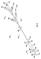
図1、2、12A、および12Bに示されるように、カテーテルアセンブリ(100)の一実施形態は、近位末端アダプタ(110)から延在して、カテーテル縦軸(170)に沿って血管(10)(図12Aおよび12B参照)内で縦方向に移動可能なカテーテル(150)を含む。カテーテル(150)は、縦軸(170)を有し、内部に5つのルーメンを画定する、長尺カテーテルシャフト(160)を含む。その遠位末端(140)において、カテーテルアセンブリ(100)は、無外傷性テーパー遠位端(200)を有する。遠位閉塞バルーン(210)はカテーテル(150)の縦軸(170)に沿ってテーパー遠位端(200)の付近に位置し、空間占有バルーン(230)はカテーテル(150)の縦軸(170)に沿って遠位閉塞バルーン(210)の付近に位置し、そして近位閉塞バルーン(250)はカテーテル(150)の縦軸(170)に沿って空間占有バルーン(230)の付近に位置する。遠位閉塞バルーン(210)および空間占有バルーン(230)の間には吸引部(220)があり、空間占有バルーン(230)および近位閉塞バルーン(250)の間には薬剤送達部(240)が位置している。吸引部(220)および薬剤送達部(240)の各々は、その内部に形成された少なくとも1つのスカイブポート(それぞれ420および440)を有する(図12Aおよび12Bも参照)。近位末端アダプタ(110)は、閉塞バルーン膨張ハブ(120)および送達ハブ(130)を含む。 As shown in FIGS. 1, 2, 12A, and 12B, one embodiment of the catheter assembly (100) extends from the proximal end adapter (110) and extends along the catheter longitudinal axis (170) to the blood vessel (170). 10) includes a catheter (150) movable longitudinally within (see FIGS. 12A and 12B). Catheter (150) includes an elongate catheter shaft (160) having a longitudinal axis (170) and defining five lumens therein. At its distal end (140), the catheter assembly (100) has an atraumatic tapered distal end (200). The distal occlusion balloon (210) is located near the tapered distal end (200) along the longitudinal axis (170) of the catheter (150) and the space occupying balloon (230) is the longitudinal axis (170) of the catheter (150). ) Located near the distal occlusion balloon (210) and the proximal occlusion balloon (250) is located near the space occupying balloon (230) along the longitudinal axis (170) of the catheter (150). . There is a suction portion (220) between the distal occlusion balloon (210) and the space occupancy balloon (230), and a drug delivery portion (240) between the space occupancy balloon (230) and the proximal occlusion balloon (250). Is located. Each of the suction portion (220) and the drug delivery portion (240) has at least one skive port (420 and 440, respectively) formed therein (see also FIGS. 12A and 12B). The proximal end adapter (110) includes an occlusion balloon inflation hub (120) and a delivery hub (130).
図1、2、および9に見られるように、閉塞バルーン膨張ハブ(120)は、遠位および近位閉塞バルーン膨張ポート(510)および空間占有バルーン膨張ポート(530)を含む。遠位および近位閉塞バルーン膨張ポート(510)は、スカイブポート(610)を通じて遠位および近位閉塞バルーン膨張ルーメン(310)に連絡し、使用中に、以下に論じられる遠位および近位閉塞バルーン(それぞれ210および250)を−相前後して−膨張および収縮させる。空間占有バルーン膨張ポート(530)は、スカイブポート(630)を通じて空間占有バルーン膨張ルーメン(330)に連絡し、使用中に、以下に論じられる空間占有バルーン(230)を−遠位および近位閉塞バルーンとは独立して−膨張および収縮させる。 As seen in FIGS. 1, 2, and 9, the occlusion balloon inflation hub (120) includes distal and proximal occlusion balloon inflation ports (510) and space occupying balloon inflation ports (530). The distal and proximal occlusion balloon inflation ports (510) communicate with the distal and proximal occlusion balloon inflation lumens (310) through the skive port (610) and in use, the distal and proximal occlusions discussed below. The balloons (210 and 250, respectively) are inflated and deflated-in phase. The space occupying balloon inflation port (530) communicates with the space occupying balloon inflation lumen (330) through the skive port (630) and, in use, disposes the space occupying balloon (230) discussed below—distal and proximal occlusion. Independent of the balloon-inflated and deflated.
図1、2、および11に見られるように、治療薬灌流/吸引および誘導線ハブ(「灌流/吸引ハブ」130)は、治療薬送達ポート(540)、治療薬吸引ポート(520)、および誘導線ポート(500)を含む。治療薬送達ポート(540)は、スカイブポート(640)を通じて治療薬送達ルーメン(340)に連絡し、スカイブポート(440)を通じて血管(10)の内腔(18)への治療薬の送達を可能にする。治療薬吸引ポート(520)は、スカイブポート(620)を通じて吸引ルーメン(320)に連絡し、スカイブポート(420)を通じて血管(10)の内腔(18)からの治療薬または流体試料の吸引を可能にする(たとえば図12B参照)。誘導線ポート(500)は誘導線ルーメン(300)に連絡しており、これはカテーテル(150)の全長にわたって延在して無外傷性テーパー端(200)において遠位開口部(202)として出現し、「オーバ・ザ・ワイヤ」での使用を可能にする。当業者によって理解されるように、そして図1、2、8、10、12A、12B、13、および15〜18において破断線で示されるように、カテーテル(100)は、近位末端アダプタ(110)が患者の体外に残ったままで遠位末端(140)が患者体内の所望の位置に到達し得るように、より長くても短くてもよい。治療薬灌流/吸引および誘導線ハブ(130)および閉塞バルーン膨張ハブ(120)の間において、カテーテル(180)は3つのルーメン(300、320、340)を保有する。 As seen in FIGS. 1, 2, and 11, the therapeutic agent perfusion / suction and guide wire hub (“perfusion / suction hub” 130) includes a therapeutic agent delivery port (540), a therapeutic agent suction port (520), and Includes a guide wire port (500). The therapeutic agent delivery port (540) communicates with the therapeutic agent delivery lumen (340) through the skive port (640) and allows delivery of the therapeutic agent to the lumen (18) of the blood vessel (10) through the skive port (440). To. The therapeutic agent aspiration port (520) communicates with the aspiration lumen (320) through the skive port (620), and draws the therapeutic agent or fluid sample from the lumen (18) of the blood vessel (10) through the skive port (420). (See FIG. 12B for example). Guide wire port (500) communicates with guide wire lumen (300), which extends the entire length of catheter (150) and appears as a distal opening (202) at the atraumatic tapered end (200). And can be used "over the wire". As understood by those skilled in the art and as shown by broken lines in FIGS. 1, 2, 8, 10, 12A, 12B, 13, and 15-18, the catheter (100) has a proximal end adapter (110 ) Remain outside the patient's body and can be longer or shorter so that the distal end (140) can reach the desired location within the patient. Between the therapeutic agent perfusion / aspiration and guide wire hub (130) and the occlusion balloon inflation hub (120), the catheter (180) carries three lumens (300, 320, 340).
ここで図1〜3、9、および11を参照すると、図3は、線B−Bを通る図1のカテーテルの断面図であり、そして:遠位閉塞バルーン(210);誘導線ポート(500)に連絡する誘導線ルーメン(300);スカイブポート(610)を通じて閉塞バルーン膨張ポート(510)に連絡する遠位および近位閉塞バルーン膨張ルーメン(310);スカイブポート(630)を通じて空間占有バルーン膨張ポート(530)に連絡する空間占有バルーン膨張ルーメン(330);スカイブポート(620)を通じて吸引ポート(520)に連絡する吸引ルーメン(320);スカイブポート(640)を通じて薬物送達ポート(540)に連絡する治療薬送達ルーメン(340);および遠位閉塞バルーン膨張スカイブポート(410)を示す。遠位閉塞バルーン膨張スカイブポート(410)は、カテーテル(150)の閉塞バルーン膨張ルーメン(310)が遠位閉塞バルーン(210)を膨張させるためにカテーテル外壁(380)に連絡するように、カテーテル外壁(380)の厚みを通じて延在する。 Referring now to FIGS. 1-3, 9, and 11, FIG. 3 is a cross-sectional view of the catheter of FIG. 1 through line BB and: distal occlusion balloon (210); guide wire port (500 A lead wire lumen (300) in communication with the occlusion balloon inflation port (510) through the skive port (610); a space-occupied balloon inflation through the skive port (630); Space-occupying balloon inflation lumen (330) in communication with port (530); suction lumen (320) in communication with suction port (520) through skive port (620); communication with drug delivery port (540) through skive port (640) Therapeutic agent delivery lumen (340); and distal occlusion balloon inflation skive port (410) Show. The distal occlusion balloon inflation skive port (410) is configured so that the occlusion balloon inflation lumen (310) of the catheter (150) communicates with the catheter outer wall (380) to inflate the distal occlusion balloon (210). Extends through the thickness of (380).
ここで図1、2、4、9、および11を参照すると、図4は線C−Cを通る図1のカテーテルの断面図であり、そして治療薬吸引部(220)の断面図を示す。ここで図1、2、4、9、および11を参照すると、図4は:誘導線ポート(500)に連絡する誘導線ルーメン(300);スカイブポート(610)を通じて閉塞バルーン膨張ポート(510)に連絡する遠位および近位閉塞バルーン膨張ルーメン(310);スカイブポート(630)を通じて空間占有バルーン膨張ポート(530)に連絡する空間占有バルーン膨張ルーメン(330);スカイブポート(620)を通じて吸引ポート(520)に連絡する吸引ルーメン(320);スカイブポート(640)を通じて灌流ポート(540)に連絡する治療薬送達ルーメン(340);および吸引スカイブポート(420)を示す。吸引スカイブポート(420)は、カテーテル(150)の吸引ルーメン(320)が治療薬または液体試料を血管(10)の内腔(18)から吸引するためにカテーテル外壁(380)に連絡するように、カテーテル外壁(380)の厚みを通じて延在する(たとえば図12Aおよび12B参照)。 Referring now to FIGS. 1, 2, 4, 9, and 11, FIG. 4 is a cross-sectional view of the catheter of FIG. 1 through line CC and shows a cross-sectional view of the therapeutic agent aspiration section (220). Referring now to FIGS. 1, 2, 4, 9, and 11, FIG. 4 shows: Guide wire lumen (300) communicating to guide wire port (500); Occlusion balloon inflation port (510) through skive port (610) Distal and proximal occlusion balloon inflation lumen (310) in communication with the space occupancy balloon inflation lumen (330) in communication with the space occupancy balloon inflation port (530) through the skive port (630); suction port through the skive port (620) A suction lumen (320) in communication with (520); a therapeutic agent delivery lumen (340) in communication with the perfusion port (540) through the skive port (640); and a suction skive port (420). The aspiration skive port (420) allows the aspiration lumen (320) of the catheter (150) to communicate with the catheter outer wall (380) to aspirate a therapeutic agent or liquid sample from the lumen (18) of the blood vessel (10). Extends through the thickness of the catheter outer wall (380) (see, eg, FIGS. 12A and 12B).
ここで図1、2、5、9、および11を参照すると、図5は線D−Dを通る図1のカテーテルの断面図であり、そして:空間占有バルーン(230);誘導線ポート(500)に連絡する誘導線ルーメン(300);スカイブポート(610)を通じて閉塞バルーン膨張ポート(510)に連絡する遠位および近位閉塞バルーン膨張ルーメン(310);スカイブポート(630)を通じて空間占有バルーン膨張ポート(530)に連絡する空間占有バルーン膨張ルーメン(330);スカイブポート(620)を通じて吸引ポート(520)に連絡する吸引ルーメン(320);スカイブポート(640)を通じて薬物送達ポート(540)に連絡する治療薬送達ルーメン(340);および空間占有バルーン膨張スカイブポート(430)を示す。空間占有バルーン膨張スカイブポート(430)は、カテーテル(150)の空間占有バルーン膨張ルーメン(330)が空間占有バルーン(230)を膨張および収縮させるためにカテーテル外壁(380)に連絡するように、カテーテル外壁(380)の厚みを通じて延在する。 Referring now to FIGS. 1, 2, 5, 9, and 11, FIG. 5 is a cross-sectional view of the catheter of FIG. 1 through line DD, and: space occupying balloon (230); guide wire port (500 A lead wire lumen (300) in communication with the occlusion balloon inflation port (510) through the skive port (610); a space-occupied balloon inflation through the skive port (630); Space-occupying balloon inflation lumen (330) in communication with port (530); suction lumen (320) in communication with suction port (520) through skive port (620); communication with drug delivery port (540) through skive port (640) Therapeutic agent delivery lumen (340); and space-occupied balloon inflation skive port (430) It is shown. The space occupying balloon inflation skive port (430) allows the space occupying balloon inflation lumen (330) of the catheter (150) to communicate with the catheter outer wall (380) to inflate and deflate the space occupying balloon (230). Extends through the thickness of the outer wall (380).
図6は線E−Eを通る図1のカテーテルの断面図であり、そして治療薬送達部(240)の断面図を示す。ここで図1、2、6、9、および11を参照すると、図6は:誘導線ポート(500)に連絡する誘導線ルーメン(300);スカイブポート(610)を通じて閉塞バルーン膨張ポート(510)に連絡する遠位および近位閉塞バルーン膨張ルーメン(310);スカイブポート(630)を通じて空間占有バルーン膨張ポート(530)に連絡する空間占有バルーン膨張ルーメン(330);スカイブポート(620)を通じて吸引ポート(520)に連絡する吸引ルーメン(320);スカイブポート(640)を通じて灌流ポート(540)に連絡する治療薬送達ルーメン(340);および薬物送達スカイブポート(440)を示す。薬物送達スカイブポート(440)は、カテーテル(150)の薬物送達ルーメン(340)が治療薬を血管(10)の内腔(18)に送達するためにカテーテル外壁(380)に連絡するように、カテーテル外壁(380)の厚みを通じて延在する(たとえば図12Aおよび12B参照)。 6 is a cross-sectional view of the catheter of FIG. 1 through line EE and shows a cross-sectional view of the therapeutic agent delivery portion (240). Referring now to FIGS. 1, 2, 6, 9, and 11, FIG. 6: Guide wire lumen (300) communicating to guide wire port (500); Occlusion balloon inflation port (510) through skive port (610) Distal and proximal occlusion balloon inflation lumen (310) in communication with the space occupancy balloon inflation lumen (330) in communication with the space occupancy balloon inflation port (530) through the skive port (630); suction port through the skive port (620) A suction lumen (320) in communication with (520); a therapeutic agent delivery lumen (340) in communication with the perfusion port (540) through the skive port (640); and a drug delivery skive port (440). The drug delivery skive port (440) is such that the drug delivery lumen (340) of the catheter (150) communicates with the catheter outer wall (380) to deliver the therapeutic agent to the lumen (18) of the blood vessel (10). It extends through the thickness of the outer catheter wall (380) (see, eg, FIGS. 12A and 12B).
ここで図1、2、7、9、および11を参照すると、図7は線F−Fを通る図1のカテーテルの断面図である。図7は:近位閉塞バルーン(250);誘導線ポート(500)に連絡する誘導線ルーメン(300);スカイブポート(610)を通じて閉塞バルーン膨張ポート(510)に連絡する遠位および近位閉塞バルーン膨張ルーメン(310);スカイブポート(630)を通じて空間占有バルーン膨張ポート(530)に連絡する空間占有バルーン膨張ルーメン(330);スカイブポート(620)を通じて吸引ポート(520)に連絡する吸引ルーメン(320);スカイブポート(640)を通じて薬物送達ポート(540)に連絡する治療薬送達ルーメン(340);および近位閉塞バルーン膨張スカイブポート(450)を示す。近位閉塞バルーン膨張スカイブポート(450)は、カテーテル(150)の閉塞バルーン膨張ルーメン(310)が近位閉塞バルーン(250)を膨張させるためにカテーテル外壁(380)に連絡するように、カテーテル外壁(380)の厚みを通じて延在する。 Referring now to FIGS. 1, 2, 7, 9, and 11, FIG. 7 is a cross-sectional view of the catheter of FIG. 1 through line FF. FIG. 7: proximal occlusion balloon (250); guide wire lumen (300) in communication with guide wire port (500); distal and proximal occlusion in communication with occlusion balloon inflation port (510) through skive port (610) Balloon inflation lumen (310); space occupation balloon inflation lumen (330) in communication with space occupation balloon inflation port (530) through skive port (630); suction lumen in communication with suction port (520) through skive port (620) 320); therapeutic drug delivery lumen (340) communicating to drug delivery port (540) through skive port (640); and proximal occlusion balloon inflation skive port (450). The proximal occlusion balloon inflation skive port (450) is configured so that the occlusion balloon inflation lumen (310) of the catheter (150) communicates with the catheter outer wall (380) to inflate the proximal occlusion balloon (250). Extends through the thickness of (380).
図3〜7を参照すると、カテーテル(160)は、カテーテル外壁(380)およびカテーテル内壁(390)を有する。図2、3〜7、9、および11からわかるように、カテーテル内壁(390)は誘導線ルーメン(300)を画定する。ルーメン(330、340、310、320)は誘導線ルーメン(300)の周辺にある;これらはカテーテル(150)の内部に形成され、そしてカテーテル内壁(390)およびカテーテル外壁(380)の間に位置する。5つのルーメン(300、310、340、330、320)はカテーテル(150)を通じて縦方向に延在し、開放近位末端(それぞれ500、510、540、530、および520)を開放遠位末端(それぞれ202、410/450、440、430、および420)と相互接続させる。 With reference to FIGS. 3-7, the catheter (160) has an outer catheter wall (380) and an inner catheter wall (390). As can be seen in FIGS. 2, 3-7, 9, and 11, the catheter inner wall (390) defines a guide wire lumen (300). Lumens (330, 340, 310, 320) are around guidewire lumen (300); they are formed inside catheter (150) and located between catheter inner wall (390) and catheter outer wall (380) To do. Five lumens (300, 310, 340, 330, 320) extend longitudinally through the catheter (150) and open proximal ends (500, 510, 540, 530, and 520, respectively) open distal ends ( 202, 410/450, 440, 430, and 420), respectively.
図8および9に見られるように、バルーン膨張ハブ(120)は、遠位末端(140)の近位および治療薬灌流/吸引および誘導線ハブ(130)から遠位にある、近位末端アダプタ(110)の部品である。治療薬灌流/吸引および誘導線ハブ(130)が遠位末端(140)およびバルーン膨張ハブ(120)の間になるように、バルーン膨張ハブ(120)および治療薬灌流/吸引および誘導線ハブ(130)の位置が互いに逆になってもよいことは、当業者によって理解されるであろう。 As seen in FIGS. 8 and 9, the balloon inflation hub (120) is proximal to the distal end (140) and distal to the therapeutic agent perfusion / aspiration and guide wire hub (130). (110) parts. The balloon inflation hub (120) and the therapeutic agent perfusion / suction and guideline hub (130) so that the therapeutic agent perfusion / suction and guideline hub (130) is between the distal end (140) and the balloon inflation hub (120). It will be understood by those skilled in the art that the positions 130) may be reversed.
バルーン膨張ハブ(120)は、閉塞バルーン膨張ポート(510)、空間占有バルーン膨張ポート(530)、およびカテーテルシャフト(160)で構成されている。閉塞バルーン膨張ポート(510)は、閉塞バルーンハブ膨張スカイブ(610)を通じてカテーテルシャフト(160)の閉塞バルーン膨張ルーメン(310)と連絡可能に接続されている。空間占有バルーン膨張ポート(530)は、空間占有バルーンハブ膨張スカイブ(630)を通じてカテーテルシャフト(160)の空間占有バルーン膨張ルーメン(330)と連絡可能に接続されている。 The balloon inflation hub (120) is comprised of an occlusion balloon inflation port (510), a space occupying balloon inflation port (530), and a catheter shaft (160). The occlusion balloon inflation port (510) is communicatively connected to the occlusion balloon inflation lumen (310) of the catheter shaft (160) through the occlusion balloon hub inflation skive (610). The space occupation balloon inflation port (530) is communicatively connected to the space occupation balloon inflation lumen (330) of the catheter shaft (160) through the space occupation balloon hub inflation skive (630).
図10および11に見られるように、治療薬灌流/吸引および誘導線ハブ(130)は、遠位末端(140)の近位およびバルーン膨張ハブ(120)の近位にある、近位末端アダプタ(110)の部品である。治療薬灌流/吸引および誘導線ハブ(130)は、治療薬灌流ポート(540)、吸引ポート(520)、誘導線ポート(500)、およびカテーテルシャフト(160)で構成されている。治療薬灌流ポート(540)は、灌流ハブスカイブ(640)を通じてカテーテルシャフト(160)の治療薬灌流ルーメン(340)と連絡可能に接続されている。吸引ポート(520)は、吸引ハブスカイブ(620)を通じてカテーテルシャフト(160)の吸引ルーメン(320)と連絡可能に接続されている。誘導線ポート(500)は誘導線ルーメン(300)と連絡可能に接続されており、これはOPC(100)の縦軸(170)を囲んでいる。本実施形態において、および図3〜7に示されるように、縦軸(170)は、誘導線ルーメン(300)の円形断面内での中心である。 As seen in FIGS. 10 and 11, the therapeutic agent perfusion / aspiration and guide wire hub (130) is proximal to the distal end (140) and proximal to the balloon inflation hub (120). (110) parts. The therapeutic agent perfusion / aspiration and guide wire hub (130) is comprised of a therapeutic agent perfusion port (540), a suction port (520), a guide wire port (500), and a catheter shaft (160). The therapeutic agent perfusion port (540) is communicatively connected to the therapeutic agent perfusion lumen (340) of the catheter shaft (160) through the perfusion hub skive (640). The suction port (520) is communicatively connected to the suction lumen (320) of the catheter shaft (160) through the suction hub skive (620). Guide wire port (500) is communicatively connected to guide wire lumen (300), which surrounds the longitudinal axis (170) of OPC (100). In this embodiment and as shown in FIGS. 3-7, the vertical axis (170) is the center of the guide wire lumen (300) within the circular cross section.
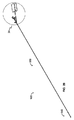
図12Aおよび12Bは、血管(10)またはその他の中空身体構造の内部で膨張したときに見えるような、遠位および近位閉塞バルーン(210、250)を示す。閉塞バルーン(210、250)、空間占有バルーン(230)、カテーテル(150、160)、および本開示の装置(100)のその他の部品が、その他の中空身体構造(たとえば、ただし限定される意図はなく、リンパ系の脈管、胃食道管、肝臓の門脈−大動脈系、胆嚢および胆管、泌尿器系、呼吸器系、内分泌および外分泌器官の管、ならびに生殖器)において必要とされるような寸法を考慮に入れて適切なサイズになり得ることは、当業者によって理解されるであろう。図12Aおよび12Bは、それぞれ膨張前および膨張後に見えるような、空間占有バルーン(230)を示す。図2、12A、および12Bを参照すると、血管(10)内のカテーテル(150)の蛍光透視下での可視化を容易にするために、空間占有バルーン(230)の「肩部」に位置する、遠位および近位放射線不透過性マーカバンド(それぞれ260、270)も示されている。放射線不透過性マーカが、カテーテルシャフト上に(たとえば、ただし非限定的に、吸引部(220)または治療薬送達部(240)に沿って)位置してもよいことは、当業者によって理解されるであろう。より好ましくは、マーカバンドの1つが吸引部(220)の最遠位部においてシャフト(150)上に位置し、第二のマーカバンドが治療薬送達部(240)の最近位部においてシャフト(150)上に位置する。あるいは、マーカバンドの1つが遠位閉塞バルーン膨張スカイブ(図3、410)上またはその付近においてシャフト(150)上に位置し、第二のマーカバンドが近位閉塞バルーン膨張スカイブ(図7、450)上またはその付近においてシャフト(150)上に位置する。これらの実施形態のいずれかにおいて、2つの放射線不透過性マーカバンドの間の間隙は治療容積および治療箇所を見積もるのに役立つ。複数ではなく、1つのマーカバンドが使用されてもよいことも、理解されるであろう。マーカが二次元蛍光透視画像において観察されるときにカテーテル(150)の遠位末端(140)の回転位置が明らかになるように、マーカバンド(260、270)は場合により回転特異性であってもよい(たとえば、実質的に「U字型」構成を有してもよい)。あるいは対照流体が、バルーンのいずれか1つまたは全て(210、230、および/または250)を膨張させるために使用されてもよく、または開口部(202)から遠位テーパー端(200)において出現するように薬物送達スカイブポート(440)を通じてまたは誘導線ルーメン(300)を通じて注入されてもよい。 12A and 12B show distal and proximal occlusion balloons (210, 250) as seen when inflated inside a blood vessel (10) or other hollow body structure. Occlusion balloons (210, 250), space occupying balloons (230), catheters (150, 160), and other parts of the device (100) of the present disclosure may be used in other hollow body structures (eg, but not limited to And as required in the lymphatic vasculature, gastroesophageal tract, liver portal-aortic system, gallbladder and bile ducts, urinary system, respiratory system, endocrine and exocrine organs, and genital organs) It will be understood by those skilled in the art that an appropriate size can be taken into account. Figures 12A and 12B show the space occupying balloon (230) as seen before and after inflation, respectively. With reference to FIGS. 2, 12A, and 12B, located in the “shoulder” of the space occupying balloon (230) to facilitate visualization of the catheter (150) in the blood vessel (10) under fluoroscopy, Distal and proximal radiopaque marker bands (260, 270, respectively) are also shown. It will be appreciated by those skilled in the art that radiopaque markers may be located on the catheter shaft (eg, but not limited to, along the suction portion (220) or therapeutic agent delivery portion (240)). It will be. More preferably, one of the marker bands is located on the shaft (150) at the most distal portion of the suction portion (220) and the second marker band is at the proximal portion of the therapeutic agent delivery portion (240). ) Located on top. Alternatively, one of the marker bands is located on the shaft (150) at or near the distal occlusion balloon inflation skive (FIGS. 3, 410) and the second marker band is a proximal occlusion balloon inflation skive (FIGS. 7, 450). ) Located on or near the shaft (150). In any of these embodiments, the gap between the two radiopaque marker bands serves to estimate the treatment volume and treatment location. It will also be appreciated that a single marker band may be used rather than a plurality. The marker band (260, 270) is optionally rotationally specific so that the rotational position of the distal end (140) of the catheter (150) becomes apparent when the marker is observed in a two-dimensional fluoroscopic image. (Eg, may have a substantially “U-shaped” configuration). Alternatively, control fluid may be used to inflate any one or all of the balloons (210, 230, and / or 250) or emerge at the distal tapered end (200) from the opening (202). As such, it may be injected through the drug delivery skive port (440) or through the guide wire lumen (300).
図12Aに見られるように、空間占有バルーン(230)の膨張を伴わない、血管(10)の内腔(20)の内部における遠位および近位閉塞バルーン(210、250)の膨張は、血管内皮(50)との接触、および比較的大きい腔内空間(30)の閉塞を招く。図12Bに示される、これに続く空間占有バルーン(230)の膨張は、比較的小さい腔内空間(40)の閉塞を生じさせるためにバルーンの外側の腔内容積を減少させ、したがって標的血管区域(60)の治療容積を減少させる。「治療容積」によって、拡張された閉塞バルーン(210、250)の間の血管の容積から空間占有バルーン(230)の容積を引いた差を意味する。結果的に、空間占有バルーンの収縮は増大された治療容積をもたらし、その一方で空間占有バルーンの膨張は治療容積を減少させる。図12Bに見られるように、バルーン(230)は血管内皮(50)と接触していないので、治療薬送達部(240)および吸引部(220)の間の流体連絡は、空間占有バルーン(230)の膨張にもかかわらず維持される(40)。 As seen in FIG. 12A, inflation of the distal and proximal occlusion balloons (210, 250) within the lumen (20) of the blood vessel (10) without inflation of the space occupying balloon (230) This results in contact with the endothelium (50) and occlusion of a relatively large intraluminal space (30). The subsequent inflation of the space-occupying balloon (230) shown in FIG. 12B reduces the intraluminal volume outside the balloon to cause occlusion of a relatively small intraluminal space (40) and thus the target vascular area. Reduce the treatment volume of (60). By “treatment volume” is meant the difference between the volume of the blood vessel between the expanded occlusion balloons (210, 250) minus the volume of the space occupying balloon (230). As a result, deflation of the space occupying balloon results in an increased treatment volume, while inflation of the space occupying balloon decreases the treatment volume. As seen in FIG. 12B, since the balloon (230) is not in contact with the vascular endothelium (50), fluid communication between the therapeutic agent delivery portion (240) and the suction portion (220) is achieved by the space-occupying balloon (230). ) Is maintained despite the expansion (40).
図3〜7に示されるように、縦軸(170)は誘導線ルーメン(300)内に収容されているが、しかし当業者は、ルーメンの配置が縦軸(170)から中央ルーメン(300)をずらすように変更されてもよいことを認識するであろう。ルーメン(330、340、310、および320)は、カテーテル(150)の内側に形成され、実質的にカテーテル外壁(380)およびカテーテル内壁(390)の間に位置する。ルーメン(300、330、340、310、および320)は、カテーテル(150)を通じて縦方向に延在するが、しかし誘導線ルーメン(300)のみがカテーテル(150)の全長にわたって開存しており、遠位テーパー端(200)において開口部(202)として出現し、そうして「オーバ・ザ・ワイヤ」での使用を可能にする。 As shown in FIGS. 3-7, the longitudinal axis (170) is contained within the guideline lumen (300), however, those skilled in the art will recognize that the arrangement of the lumens from the longitudinal axis (170) to the central lumen (300). It will be appreciated that changes may be made to stagger. Lumens (330, 340, 310, and 320) are formed inside catheter (150) and are located substantially between catheter outer wall (380) and catheter inner wall (390). The lumens (300, 330, 340, 310, and 320) extend longitudinally through the catheter (150), but only the guide wire lumen (300) is patent over the entire length of the catheter (150), Appears as an opening (202) at the distal tapered end (200), thus allowing for "over the wire" use.
遠位閉塞バルーン(210)および近位閉塞バルーン(250)の膨張は、図12Aに示されるように、遠位方向および近位方向を膨張した遠位および近位閉塞バルーン(それぞれ210および250)によって囲まれ、周囲を血管(10)によって囲まれている、実質的に円筒形の送達域を形成する。遠位および近位閉塞バルーン(それぞれ210および250)は、順応性ないし半順応性材料(たとえば、ポリエチレンテレフタレート、ナイロン、ポリウレタン、またはその他の熱可塑性ポリマなど、ただしこれらに限定されない)で構成され、つまりこれらが力を発生し、血管に過剰な圧力を与えることなく血流に対する封止を形成するように、自身の形状を維持する。しかし、遠位および近位閉塞バルーン(それぞれ210および250)が膨張して空間充填バルーン(230)が収縮するだけで、図12Aに示されるように、比較的大きい治療容積が、閉塞された血管腔(30)内に残る。この大きな容積は、希少または高価な薬剤が送達されるときに、特に望ましくない;より大量のこれらの薬剤が必要とされるので、毒物が送達されるときには有害となる可能性がある。このため、より大きい治療容積は、より高い費用および危険性を生じる。 Inflation of the distal occlusion balloon (210) and the proximal occlusion balloon (250) is achieved by distal and proximal occlusion balloons (210 and 250, respectively) expanded in the distal and proximal directions, as shown in FIG. 12A. And forms a substantially cylindrical delivery zone surrounded by a blood vessel (10). The distal and proximal occlusion balloons (210 and 250, respectively) are composed of a compliant or semi-compliant material (such as, but not limited to, polyethylene terephthalate, nylon, polyurethane, or other thermoplastic polymer) That is, they generate forces and maintain their shape so that they form a seal against blood flow without applying excessive pressure to the blood vessels. However, just as the distal and proximal occlusion balloons (210 and 250, respectively) are inflated and the space-filling balloon (230) is deflated, a relatively large treatment volume can be achieved as shown in FIG. 12A. It remains in the cavity (30). This large volume is particularly undesirable when rare or expensive drugs are delivered; since larger quantities of these drugs are required, they can be detrimental when toxic agents are delivered. Thus, a larger treatment volume results in higher costs and risks.
空間占有バルーン(230)の膨張は、図12Bに示されるように、閉塞された血管腔(40)内に残る空間を劇的に減少させ、それによって、必要とされる薬剤の量を同時に減少させながら、送達される薬剤の効果的な適用を増加させる。空間占有バルーン(230)は、非順応性ないし半順応性材料(たとえば、ポリウレタン、ナイロンエラストマ、ポリエチレンテレフタレート、またはその他の熱可塑性ポリマなど、ただしこれらに限定されない)で構成される。空間占有バルーン(230)は、血管内皮(50)と接触しない程度まで膨張され、このため膨張した遠位および近位閉塞バルーン(それぞれ210および250)の間の内皮(50)の全領域を、送達された薬剤への曝露に利用可能なままにする。 The expansion of the space occupying balloon (230) dramatically reduces the space left in the occluded vessel lumen (40), as shown in FIG. 12B, thereby simultaneously reducing the amount of drug required. While increasing the effective application of the delivered drug. The space occupying balloon (230) is constructed of a non-compliant or semi-compliant material (such as, but not limited to, polyurethane, nylon elastomer, polyethylene terephthalate, or other thermoplastic polymer). The space occupying balloon (230) is inflated to such an extent that it does not contact the vascular endothelium (50), so that the entire area of the endothelium (50) between the inflated distal and proximal occlusion balloons (210 and 250, respectively) Leave available for exposure to the delivered drug.
一実施形態において、誘導線ルーメン(300)は、無外傷性テーパー端(200)の遠位開口部(202)を通る、誘導線(図示せず)へのアクセスを提供し、その一方で遠位および近位閉塞バルーン膨張ルーメン(310)ならびに空間占有バルーン膨張ルーメン(330)は、それぞれ遠位(210)および近位(250)閉塞バルーンならびに空間占有バルーン(230)用のバルーン膨張ポート(それぞれ510および530)向けのアクセスを提供する。薬剤送達ポート(540)はスカイブポート(640)を通じて薬剤送達ルーメン(340)に連絡し、薬剤送達ルーメン(340)もまた、閉塞された血管腔(18、30、40)への治療薬の送達のため、薬剤送達部(240)におけるスカイブポート(440)を通じて血管腔(18)に連絡している。吸引ポート(520)はスカイブポート(620)を通じて吸引ルーメン(320)に連絡し、吸引ルーメン(320)は、血管腔(18、30、40)からの薬剤またはその他の流体試料の吸引のために、吸引部(220)におけるスカイブポート(420)を通じて血管腔(18)に連絡している。本実施形態の一態様において、吸引ルーメン(320)を通じての注入、薬剤送達ルーメン(340)を通じての吸引または逆流、あるいは両方(それぞれ)を防止するために、薬剤送達ルーメン(340)、吸引ルーメン(図16および17において、320)、またはその両方と流体連絡する、二方または三方弁あるいは逆止弁(710)が設けられてもよい。 In one embodiment, the guide wire lumen (300) provides access to a guide wire (not shown) through the distal opening (202) of the atraumatic tapered end (200), while far away. The proximal and proximal occlusion balloon inflation lumen (310) and the space occupancy balloon inflation lumen (330) are respectively balloon inflation ports (respectively) for the distal (210) and proximal (250) occlusion balloons and the space occupation balloon (230), respectively. 510 and 530). The drug delivery port (540) communicates with the drug delivery lumen (340) through the skive port (640), which also delivers the therapeutic agent to the occluded vessel lumen (18, 30, 40). Therefore, it communicates with the blood vessel cavity (18) through the skive port (440) in the drug delivery unit (240). The aspiration port (520) communicates with the aspiration lumen (320) through the skive port (620), and the aspiration lumen (320) is for aspiration of a drug or other fluid sample from the vessel lumen (18, 30, 40). , Communicating with the blood vessel cavity (18) through the skive port (420) in the suction part (220). In one aspect of this embodiment, in order to prevent infusion through the suction lumen (320), suction or backflow through the drug delivery lumen (340), or both (respectively), the drug delivery lumen (340), the suction lumen ( 16 and 17, a two-way or three-way valve or check valve (710) may be provided that is in fluid communication with 320), or both.
本実施形態の別の態様において、カテーテル(100)は、カテーテルシャフト(190、192)およびアダプタ(110)のハブ(130a)に組み込まれた、図13〜15および18に見られるような、第一圧力検知手段(700)を含んでもよい。これによって限定されることを意図するものではなく、適切な圧力検知手段(700)の一例は、FOP−MIV(Sequoia Technology, Ltd.;英国、Reading)−光ファイバ圧力センサである。このような圧力検知手段は、遠位末端(702)、圧力センサコネクタ(550)に位置する近位末端(701)、およびその間の長さを有する。治療薬灌流ルーメン(340)と流体連絡している圧力センサコネクタ(550)を通じて、圧力検知手段は治療薬灌流ルーメン(340)に侵入し、図14に示されるように、治療薬送達部(240)の灌流/送達スカイブ(440)上またはその付近の位置まで延在する。スカイブ(440)を通じて、カテーテル(150)の治療薬送達ルーメン(340)は、図12Aおよび12Bに見られるように、血管(10)の内腔(18、30、40)に治療薬を送達するために、カテーテル外壁(380)に連絡している。このため、圧力検知手段遠位末端(702)は治療域(60)に連絡している。本開示のカテーテル(100)のこの態様において、吸引ルーメン(320)を通じての注入、薬剤送達ルーメン(340)を通じての吸引または逆流、あるいは両方(それぞれ)を防止するために、薬剤送達ルーメン(340)、吸引ルーメン(図16〜17に示されるように、吸引ポート(520)を通じて、320)、またはその両方と直列の、二方または三方弁あるいは逆止弁(710)が設けられてもよい。明確さのため、および冗長さを減じるため、二方または三方弁あるいは逆止弁(710)は、吸引ポート(520)に取り付けられた状態で示されている。1つまたは複数のこのような弁(710)がいずれのポート(500、510、520、530、540)に組み込まれてもよいことは、当業者によって理解されるであろう。当業者によって理解されるように、カテーテル(100)はまた、第一圧力検知手段(700)がカテーテル(150)内で自身の個別及び専用ルーメンを占有するように構成されてもよく、圧力センサコネクタ(550)における近位開口部および灌流/送達スカイブ(440)におけるまたはその付近の遠位開口部を有していてもよい。治療薬灌流/吸引/誘導線/圧力センサハブ(130a)および閉塞バルーン膨張ハブ(120)の間において、図15および18に示されるように、カテーテル(190)は、3つのルーメン(300、320、340)を保有するが、しかし第一圧力センサ(700)を収容するための専用ルーメンを保有してもよい。 In another aspect of this embodiment, the catheter (100) is a second one, as seen in FIGS. 13-15 and 18, incorporated into the catheter shaft (190, 192) and the hub (130a) of the adapter (110). One pressure sensing means (700) may be included. Without intending to be limited thereby, an example of a suitable pressure sensing means (700) is the FOP-MIV (Sequoia Technology, Ltd .; Reading, UK) -fiber optic pressure sensor. Such pressure sensing means has a distal end (702), a proximal end (701) located at the pressure sensor connector (550), and a length therebetween. Through the pressure sensor connector (550) in fluid communication with the therapeutic agent perfusion lumen (340), the pressure sensing means enters the therapeutic agent perfusion lumen (340) and, as shown in FIG. ) To or near the perfusion / delivery skive (440). Through the skive (440), the therapeutic agent delivery lumen (340) of the catheter (150) delivers the therapeutic agent to the lumen (18, 30, 40) of the blood vessel (10), as seen in FIGS. 12A and 12B. For this purpose, the outer wall of the catheter (380) is communicated. Thus, the pressure sensing means distal end (702) is in communication with the treatment zone (60). In this aspect of the catheter (100) of the present disclosure, drug delivery lumen (340) to prevent infusion through suction lumen (320), suction or backflow through drug delivery lumen (340), or both (respectively). A two-way or three-way valve or check valve (710) in series with the suction lumen (through the suction port (520), 320 as shown in FIGS. 16-17), or both, may be provided. For clarity and to reduce redundancy, a two-way or three-way valve or check valve (710) is shown attached to the suction port (520). It will be appreciated by one skilled in the art that one or more such valves (710) may be incorporated into any port (500, 510, 520, 530, 540). As will be appreciated by those skilled in the art, the catheter (100) may also be configured such that the first pressure sensing means (700) occupies its own and dedicated lumens within the catheter (150). It may have a proximal opening at the connector (550) and a distal opening at or near the perfusion / delivery skive (440). Between the therapeutic agent perfusion / aspiration / guideline / pressure sensor hub (130a) and the occlusion balloon inflation hub (120), as shown in FIGS. 15 and 18, the catheter (190) has three lumens (300, 320, 340), but may also have a dedicated lumen for housing the first pressure sensor (700).
本実施形態の関連する態様において、図18に示されるように、本開示のカテーテル(100)は、カテーテルシャフト(190、192)およびアダプタ(110)のハブ(130a)に組み込まれた第二圧力検知手段(704)をさらに含んでもよく、これによって、−灌流スカイブ(640)におけるまたはその付近の、あるいは治療薬灌流ルーメン(340)内のいずれかの位置における−治療薬灌流ルーメン(340)内の流体環境の圧力が知られ、または予測されることが可能である。本態様において、第二圧力検知手段(704)は、第二圧力検知手段近位末端(705)もまた圧力センサコネクタ(550)に位置した状態で、ただしその遠位末端(706)が灌流スカイブ(640)上またはその付近で治療薬灌流ルーメン(340)内に、あるいは治療薬灌流ルーメン(340)内のいずれかの場所に位置した状態で、第一圧力検知手段(700)の近位末端に沿って位置してもよい。特定の圧力センサに縛られると意図することなく、この実施形態に適した圧力センサの一例は、FOP−MIV(Sequoia Technology, Ltd.;英国、Reading)−光ファイバ圧力センサである。第二圧力検知手段(704)を通じて、装置(100)のユーザは、灌流スカイブ(640)においてまたはその付近で治療薬にかかる圧力を知る、または予測することができる。このような情報は、生細胞懸濁液あるいは圧力および/またはせん断応力の影響を受けやすいその他の材料としてのこのような薬剤の送達に、特に関連がある可能性がある。本実施形態において、および第一圧力検知手段(700)を備える例について上記で説明されたように、吸引ルーメン(320)を通じての注入、薬剤送達ルーメン(340)を通じての吸引または逆流、あるいは両方(それぞれ)を防止するために、薬剤送達ルーメン(340)、吸引ルーメン(図16〜17に示されるように、吸引ポート(520)を通じて、320)、またはその両方と直列の、二方または三方弁あるいは逆止弁(710)が設けられてもよい。 In a related aspect of this embodiment, as shown in FIG. 18, the catheter (100) of the present disclosure includes a second pressure built into the catheter shaft (190, 192) and the hub (130a) of the adapter (110). Sensing means (704) may further be included, thereby: -in or near the perfusion skive (640) or at any location in the therapeutic agent perfusion lumen (340) -in the therapeutic agent perfusion lumen (340) The pressure of the fluid environment can be known or predicted. In this embodiment, the second pressure sensing means (704) has the second pressure sensing means proximal end (705) also located at the pressure sensor connector (550), but its distal end (706) is a perfusion skive. (640) The proximal end of the first pressure sensing means (700) with or positioned within or near the therapeutic agent perfusion lumen (340) or anywhere within the therapeutic agent perfusion lumen (340). You may be located along. Without intending to be tied to a particular pressure sensor, one example of a pressure sensor suitable for this embodiment is the FOP-MIV (Sequoia Technology, Ltd .; Reading, UK) -fiber optic pressure sensor. Through the second pressure sensing means (704), the user of the device (100) can know or predict the pressure on the therapeutic agent at or near the perfusion skive (640). Such information may be particularly relevant to the delivery of such agents as live cell suspensions or other materials that are sensitive to pressure and / or shear stress. In this embodiment, and as described above for the example comprising the first pressure sensing means (700), infusion through the suction lumen (320), aspiration or backflow through the drug delivery lumen (340), or both ( Two-way or three-way valve in series with drug delivery lumen (340), suction lumen (through suction port (520), 320 as shown in FIGS. 16-17), or both, to prevent each Alternatively, a check valve (710) may be provided.
図19A〜Cおよび25〜30に示されるように、カテーテルアセンブリ(105)の実施形態は、近位末端アダプタ(110)から延在して、カテーテル縦軸(170)に沿って血管(10)内で縦方向に移動可能なカテーテル(150)を含む。カテーテル(150)は、縦軸(170)を有し、内部に5つのルーメンを画定する、長尺カテーテルシャフト(160)を含む。その遠位末端(140)において、カテーテルアセンブリ(105)は、無外傷性テーパー遠位端(200)を有する。遠位閉塞バルーン(210)はカテーテル(150)の縦軸(170)に沿ってテーパー遠位端(200)の近位に位置し、可視化手段スロット(435)はカテーテル(150)の縦軸(170)に沿って遠位閉塞バルーン(210)の近位に位置し、そして近位閉塞バルーン(250)はカテーテル(150)の縦軸(170)に沿って可視化手段スロット(435)の近位に位置する。遠位閉塞バルーン(210)および可視化手段スロット(435)の間には吸引部(220)があり、可視化手段スロット(435)および近位閉塞バルーン(250)の間には薬剤送達部(240)が位置している。吸引部(220)および薬剤送達部(240)の各々は、その内部に形成された少なくとも1つのスカイブポート(それぞれ420および440)を有する(図12Aおよび12Bも参照)。近位末端アダプタ(110)は、バルーン膨張/可視化および照明手段ハブ(125)および送達ハブ(130)を含む。 As shown in FIGS. 19A-C and 25-30, an embodiment of the catheter assembly (105) extends from the proximal end adapter (110) and extends along the catheter longitudinal axis (170) to the blood vessel (10). A catheter (150) movable longitudinally therein. Catheter (150) includes an elongate catheter shaft (160) having a longitudinal axis (170) and defining five lumens therein. At its distal end (140), the catheter assembly (105) has an atraumatic tapered distal end (200). The distal occlusion balloon (210) is located proximal to the tapered distal end (200) along the longitudinal axis (170) of the catheter (150), and the visualization means slot (435) is the longitudinal axis of the catheter (150) ( 170) is located proximal of the distal occlusion balloon (210) and the proximal occlusion balloon (250) is proximal of the visualization means slot (435) along the longitudinal axis (170) of the catheter (150). Located in. There is a suction portion (220) between the distal occlusion balloon (210) and the visualization means slot (435), and a drug delivery portion (240) between the visualization means slot (435) and the proximal occlusion balloon (250). Is located. Each of the suction portion (220) and the drug delivery portion (240) has at least one skive port (420 and 440, respectively) formed therein (see also FIGS. 12A and 12B). The proximal end adapter (110) includes a balloon inflation / visualization and illumination means hub (125) and a delivery hub (130).
図19A〜C、20〜24、および30に見られるように、バルーン膨張/可視化および照明手段ハブ(125)は、遠位および近位閉塞バルーン膨張ポート(510)および可視化手段ポート(535)(たとえば図19B参照)を含む。遠位および近位閉塞バルーン膨張ポート(510)は、スカイブポート(610)を通じて遠位および近位閉塞バルーン膨張ルーメン(310)に連絡し、使用中に、以下に論じられる遠位および近位閉塞バルーン(それぞれ210および250)を−相前後して−膨張および収縮させる。可視化手段ポート(535)はスカイブポート(635)を通じて可視化手段ルーメン(335)に連絡し、以下に論じられる可視化手段(235)に、可視化手段スロット(435)に到達してそこから出現するまで可視化手段ルーメン(335)内を通過させる。可視化手段ポート(535)は、可視化手段ルーメン(335)を通じての逆流を防止するために、弁(710)(たとえばTuohy Borstアダプタ、二方、三方、または逆止弁など)をさらに含んでもよい。可視化手段(235)は出力部(238)をさらに含み、これによって可視化手段(235)は(たとえばモニタ、コンピュータなどへ)情報を運んでもよく、容易に利用可能なおよび当技術分野において周知の手段によって、可視化および/または記録されてもよい。 As seen in FIGS. 19A-C, 20-24, and 30, the balloon inflation / visualization and illumination means hub (125) includes distal and proximal occlusion balloon inflation ports (510) and visualization means ports (535) ( For example, see FIG. 19B). The distal and proximal occlusion balloon inflation ports (510) communicate with the distal and proximal occlusion balloon inflation lumens (310) through the skive port (610) and in use, the distal and proximal occlusions discussed below. The balloons (210 and 250, respectively) are inflated and deflated-in phase. The visualization means port (535) communicates with the visualization means lumen (335) through the skive port (635) and visualization until the visualization means slot (435) reaches and emerges from the visualization means (235) discussed below. Pass through means lumen (335). The visualization means port (535) may further include a valve (710) (eg, Tuohy Borst adapter, two-way, three-way, or check valve) to prevent backflow through the visualization means lumen (335). The visualization means (235) further includes an output (238) whereby the visualization means (235) may carry information (eg, to a monitor, computer, etc.) and is readily available and well known in the art. May be visualized and / or recorded.
図19A〜C、20〜24、および30に見られるように、治療薬灌流/吸引および誘導線ハブ(「灌流/吸引ハブ」、130)は、治療薬送達ポート(540)、治療薬吸引ポート(520)、および誘導線ポート(500)を含む(図19C参照)。治療薬送達ポート(540)は、スカイブポート(640)を通じて治療薬送達ルーメン(340)に連絡し、スカイブポート(440)を通じて血管(10)の内腔(18)までの治療薬の送達を可能にする(たとえば図12Aおよび12B参照)。治療薬吸引ポート(520)は、スカイブポート(620)を通じて吸引ルーメン(320)に連絡し、スカイブポート(420)を通じて血管(10)の内腔(18)からの治療薬または流体試料の吸引を可能にする(たとえば図12Aおよび12B参照)。誘導線ポート(500)は誘導線ルーメン(300)に連絡しており、これはカテーテル(150)の全長にわたって延在して無外傷性テーパー端(200)において遠位開口部(202)として出現し、「オーバ・ザ・ワイヤ」での使用を可能にする。当業者によって理解されるように、そして図19において破断線で示されるように、カテーテル(150)は、近位末端アダプタ(110)が患者の体外に残ったままで遠位末端(140)が患者体内の所望の位置に到達し得るように、より長くても短くてもよい。治療薬灌流/吸引および誘導線ハブ(130)およびバルーン膨張/可視化および照明手段ハブ(125)の間において、カテーテル(180)は3つのルーメン(300、320、340)を保有する。 As seen in FIGS. 19A-C, 20-24, and 30, the therapeutic agent perfusion / aspiration and guide wire hub ("perfusion / aspiration hub", 130) is a therapeutic agent delivery port (540), therapeutic agent aspiration port. (520) and a guide wire port (500) (see FIG. 19C). The therapeutic agent delivery port (540) communicates with the therapeutic agent delivery lumen (340) through the skive port (640) and allows delivery of the therapeutic agent through the skive port (440) to the lumen (18) of the blood vessel (10). (See, eg, FIGS. 12A and 12B). The therapeutic agent aspiration port (520) communicates with the aspiration lumen (320) through the skive port (620), and draws the therapeutic agent or fluid sample from the lumen (18) of the blood vessel (10) through the skive port (420). (See, eg, FIGS. 12A and 12B). Guide wire port (500) communicates with guide wire lumen (300), which extends the entire length of catheter (150) and appears as a distal opening (202) at the atraumatic tapered end (200). And can be used "over the wire". As understood by those skilled in the art and as shown by the broken line in FIG. 19, the catheter (150) has a proximal end adapter (110) left outside the patient's body and a distal end (140) at the patient. It may be longer or shorter so that it can reach a desired position in the body. Between the therapeutic agent perfusion / aspiration and guide wire hub (130) and the balloon inflation / visualization and illumination means hub (125), the catheter (180) carries three lumens (300, 320, 340).
ここで図19A〜C、20、および25〜28を参照すると、図20は線I−Iを通る図19のカテーテルの断面図であり、そして:遠位閉塞バルーン(210);誘導線ポート(500)に連絡する誘導線ルーメン(300);スカイブポート(610)を通じて閉塞バルーン膨張ポート(510)に連絡する遠位および近位閉塞バルーン膨張ルーメン(310);スカイブポート(635)を通じて可視化手段ポート(535)に連絡する可視化手段ルーメン(335);スカイブポート(620)を通じて吸引ポート(520)に連絡する吸引ルーメン(320);スカイブポート(640)を通じて薬物送達ポート(540)に連絡する治療薬送達ルーメン(340);および遠位閉塞バルーン膨張スカイブポート(410)を示す。遠位閉塞バルーン膨張スカイブポート(410)は、カテーテル(150)の閉塞バルーン膨張ルーメン(310)が遠位閉塞バルーン(210)を膨張させるためにカテーテル外壁(380)に連絡するように、カテーテル外壁(380)の厚みを通じて延在する。 Referring now to FIGS. 19A-C, 20, and 25-28, FIG. 20 is a cross-sectional view of the catheter of FIG. 19 through line II and: and distal occlusion balloon (210); guide wire port ( 500) to the occlusion balloon inflation port (510) through the skive port (610); the visualization means port through the skive port (635); Visualization means lumen (335) in communication with (535); suction lumen (320) in communication with suction port (520) through skive port (620); therapeutic agent in communication with drug delivery port (540) through skive port (640) Shows delivery lumen (340); and distal occlusion balloon inflation skive port (410)The distal occlusion balloon inflation skive port (410) is configured so that the occlusion balloon inflation lumen (310) of the catheter (150) communicates with the catheter outer wall (380) to inflate the distal occlusion balloon (210). Extends through the thickness of (380).
ここで図19A〜C、21、および25〜28を参照すると、図21は線J−Jを通る図19のカテーテルの断面図であり、そして:誘導線ポート(500)に連絡する誘導線ルーメン(300);スカイブポート(610)を通じて閉塞バルーン膨張ポート(510)に連絡する遠位および近位閉塞バルーン膨張ルーメン(310);スカイブポート(635)を通じて可視化手段ポート(535)に連絡する可視化手段ルーメン(335);スカイブポート(620)を通じて吸引ポート(520)に連絡する吸引ルーメン(320);スカイブポート(640)を通じて灌流ポート(540)に連絡する治療薬送達ルーメン(340);および 吸引スカイブポート(420)を示す、治療薬吸引部(220)の断面図を示す。吸引スカイブポート(420)は、カテーテル(150)の吸引ルーメン(320)が治療薬または液体試料を血管(10)の内腔(18)から吸引するためにカテーテル外壁(380)に連絡するように、カテーテル外壁(380)の厚みを通じて延在する(たとえば図12Aおよび12B参照)。 Referring now to FIGS. 19A-C, 21, and 25-28, FIG. 21 is a cross-sectional view of the catheter of FIG. 19 through line JJ, and: Guide wire lumen communicating to guide wire port (500) (300); distal and proximal occlusion balloon inflation lumens (310) in communication with occlusion balloon inflation port (510) through skive port (610); visualization means in communication with visualization means port (535) through skive port (635) A lumen (335); a suction lumen (320) in communication with the suction port (520) through the skive port (620); a therapeutic agent delivery lumen (340) in communication with the perfusion port (540) through the skive port (640); and a suction skive FIG. 6 shows a cross-sectional view of the therapeutic drug suction portion (220) showing the port (420). The aspiration skive port (420) allows the aspiration lumen (320) of the catheter (150) to communicate with the catheter outer wall (380) to aspirate a therapeutic agent or liquid sample from the lumen (18) of the blood vessel (10). Extends through the thickness of the catheter outer wall (380) (see, eg, FIGS. 12A and 12B).
ここで図19A〜C、22、および25〜28を参照すると、図22は線K−Kを通る図19のカテーテルの断面図であり、そして:誘導線ポート(500)に連絡する誘導線ルーメン(300);スカイブポート(610)を通じて閉塞バルーン膨張ポート(510)に連絡する遠位および近位閉塞バルーン膨張ルーメン(310);スカイブポート(635)を通じて可視化手段ポート(535)に連絡する、可視化手段ルーメン(335)内に収容された可視化手段(235);スカイブポート(620)を通じて吸引ポート(520)に連絡する吸引ルーメン(320);スカイブポート(640)を通じて薬物送達ポート(540)に連絡する治療薬送達ルーメン(340);および空間占有バルーン膨張スカイブポート(430)を示す。可視化手段スロット(435)は、カテーテル(150)の可視化手段ルーメン(335)が可視化手段(235)を可視化手段スロット(435)およびルーメン(335)から脱出させて血管(10)の内腔(18)に侵入させるためにカテーテル外壁(380)に連絡するように、カテーテル外壁(380)の厚みを通じて延在する。可視化手段スロット(435)は、図27および28に示されるように、可視化手段(235)を可視化手段スロット(435)から脱出させるのに十分な長さだけ、縦軸(170)と平行に、吸引部(220)および治療薬送達部(240)の間を延在する。可視化手段スロット(435)から出ることにより、可視化手段(235)は、360度方向の血管腔(つまり、カテーテル自体によって視界を遮られることなく、血管内壁の全て)の可視化を可能にする。 Referring now to FIGS. 19A-C, 22, and 25-28, FIG. 22 is a cross-sectional view of the catheter of FIG. 19 through line KK, and: a guide wire lumen in communication with guide wire port (500) (300); distal and proximal occlusion balloon inflation lumen (310) in communication with occlusion balloon inflation port (510) through skive port (610); visualization in communication with visualization means port (535) through skive port (635) Visualization means (235) housed in means lumen (335); suction lumen (320) communicating to suction port (520) through skive port (620); communicating drug delivery port (540) through skive port (640) Therapeutic agent delivery lumen (340); and space-occupied balloon inflation skive port (430) It is shown. The visualization means slot (435) allows the visualization means lumen (335) of the catheter (150) to disengage the visualization means (235) from the visualization means slot (435) and lumen (335), so that the lumen (18) of the blood vessel (10) ) Extends through the thickness of the catheter outer wall (380) so as to communicate with the catheter outer wall (380) for intrusion. The visualization means slot (435) is parallel to the longitudinal axis (170) long enough to allow the visualization means (235) to escape from the visualization means slot (435), as shown in FIGS. It extends between the suction portion (220) and the therapeutic agent delivery portion (240). By exiting the visualization means slot (435), the visualization means (235) allows visualization of the 360 degree vascular lumen (ie, all of the vessel inner wall without being obstructed by the catheter itself).
ここで図19A〜C、23、および25〜28を参照すると、図23は線L−Lを通る図19のカテーテルの断面図であり、そして:誘導線ポート(500)に連絡する誘導線ルーメン(300);スカイブポート(610)を通じて閉塞バルーン膨張ポート(510)に連絡する遠位および近位閉塞バルーン膨張ルーメン(310);スカイブポート(635)を通じて可視化手段ポート(535)に連絡する可視化手段ルーメン(335)に収容された可視化手段(235);スカイブポート(620)を通じて吸引ポート(520)に連絡する吸引ルーメン(320);スカイブポート(640)を通じて灌流ポート(540)に連絡する治療薬送達ルーメン(340);および薬物送達スカイブポート(440)を示す。薬物送達スカイブポート(440)は、カテーテル(150)の薬物送達ルーメン(340)が治療薬を血管(10)の内腔(18)に送達するためにカテーテル外壁(380)に連絡するように、カテーテル外壁(380)の厚みを通じて延在する(たとえば図12Aおよび12B参照)。 Referring now to FIGS. 19A-C, 23, and 25-28, FIG. 23 is a cross-sectional view of the catheter of FIG. 19 through line LL, and: a guide wire lumen in communication with guide wire port (500) (300); distal and proximal occlusion balloon inflation lumens (310) in communication with occlusion balloon inflation port (510) through skive port (610); visualization means in communication with visualization means port (535) through skive port (635) Visualization means (235) contained in lumen (335); suction lumen (320) communicating with suction port (520) through skive port (620); therapeutic agent communicating with perfusion port (540) through skive port (640) A delivery lumen (340); and a drug delivery skive port (440) are shown. The drug delivery skive port (440) is such that the drug delivery lumen (340) of the catheter (150) communicates with the catheter outer wall (380) to deliver the therapeutic agent to the lumen (18) of the blood vessel (10). It extends through the thickness of the outer catheter wall (380) (see, eg, FIGS. 12A and 12B).
ここで図19A〜C、24、および25〜28を参照すると、図24は線M−Mを通る図19のカテーテルの断面図であり、そして:近位閉塞バルーン(250);誘導線ポート(500)に連絡する誘導線ルーメン(300);スカイブポート(610)を通じて閉塞バルーン膨張ポート(510)に連絡する遠位および近位閉塞バルーン膨張ルーメン(310);スカイブポート(635)を通じて可視化手段ポート(535)に連絡する可視化手段ルーメン(335)に収容された可視化手段(235);スカイブポート(620)を通じて吸引ポート(520)に連絡する吸引ルーメン(320);スカイブポート(640)を通じて薬物送達ポート(540)に連絡する治療薬送達ルーメン(340);および近位閉塞バルーン膨張スカイブポート(450)を示す。近位閉塞バルーン膨張スカイブポート(450)は、カテーテル(150)の閉塞バルーン膨張ルーメン(310)が近位閉塞バルーン(250)を膨張させるためにカテーテル外壁(380)に連絡するように、カテーテル外壁(380)の厚みを通じて延在する。 Referring now to FIGS. 19A-C, 24, and 25-28, FIG. 24 is a cross-sectional view of the catheter of FIG. 19 through line MM, and: proximal occlusion balloon (250); guide wire port ( 500) to the occlusion balloon inflation port (510) through the skive port (610); the visualization means port through the skive port (635); Visualization means (235) housed in visualization means lumen (335) communicating with (535); suction lumen (320) communicating with suction port (520) through skive port (620); drug delivery through skive port (640) Therapeutic agent delivery lumen (340) in communication with port (540); and proximal occlusion balloon inflation Skive shows the port (450). The proximal occlusion balloon inflation skive port (450) is configured so that the occlusion balloon inflation lumen (310) of the catheter (150) communicates with the catheter outer wall (380) to inflate the proximal occlusion balloon (250). Extends through the thickness of (380).
ここで図20〜24を参照すると、カテーテル(160)は、カテーテル外壁(380)およびカテーテル内壁(390)を有する。図19A〜Cおよび20〜28からわかるように、カテーテル内壁(390)は誘導線ルーメン(300)を画定する。ルーメン(335、340、310、320)は誘導線ルーメン(300)の周辺にある;これらはカテーテル(150)の内部に形成され、そしてカテーテル内壁(390)およびカテーテル外壁(380)の間に位置する。5つのルーメン(300、310、340、335、320)はカテーテル(150)を通じて縦方向に延在し、開放近位末端(それぞれ500、510、540、535、および520)を開放遠位末端(それぞれ202、410/450、440、435、および420)と相互接続させる。 Referring now to FIGS. 20-24, the catheter (160) has a catheter outer wall (380) and a catheter inner wall (390). As can be seen from FIGS. 19A-C and 20-28, the catheter inner wall (390) defines a guide wire lumen (300). Lumens (335, 340, 310, 320) are around guidewire lumen (300); they are formed inside catheter (150) and located between catheter inner wall (390) and catheter outer wall (380) To do. Five lumens (300, 310, 340, 335, 320) extend longitudinally through the catheter (150) and open proximal ends (500, 510, 540, 535, and 520, respectively) open distal ends ( 202, 410/450, 440, 435, and 420), respectively.
図19Aおよび19Bに見られるように、バルーン膨張/可視化および照明手段ハブ(125)は、遠位末端(140)の近位および治療薬灌流/吸引および誘導線ハブ(130)から遠位にある、近位末端アダプタ(110)の部品である。治療薬灌流/吸引および誘導線ハブ(130)が遠位末端(140)並びにバルーン膨張/可視化および照明手段ハブ(125)の間になるように、バルーン膨張/可視化および照明手段ハブ(125)並びに治療薬灌流/吸引および誘導線ハブ(130)の位置が互いに逆になってもよいことは、当業者によって理解されるであろう。バルーン膨張/可視化および照明手段ハブ(125)は、閉塞バルーン膨張ポート(510)、可視化手段ポート(535)、およびカテーテルシャフト(160)で構成されている。閉塞バルーン膨張ポート(510)は、閉塞バルーンハブ膨張スカイブ(610)を通じてカテーテルシャフト(160)の閉塞バルーン膨張ルーメン(310)と連絡可能に接続されている。可視化手段ポート(535)は、スカイブポート(635)を通じてカテーテルシャフト(160)の可視化手段ルーメン(335)と連絡可能に接続されている。 As seen in FIGS. 19A and 19B, the balloon inflation / visualization and illumination means hub (125) is proximal to the distal end (140) and distal from the therapeutic agent perfusion / aspiration and guide wire hub (130). , Part of the proximal end adapter (110). Balloon inflation / visualization and illumination means hub (125) and therapeutic agent perfusion / aspiration and guide wire hub (130) between distal end (140) and balloon inflation / visualization and illumination means hub (125) and It will be appreciated by those skilled in the art that the location of the therapeutic agent perfusion / aspiration and guide wire hub (130) may be reversed. The balloon inflation / visualization and illumination means hub (125) is comprised of an occlusion balloon inflation port (510), a visualization means port (535), and a catheter shaft (160). The occlusion balloon inflation port (510) is communicatively connected to the occlusion balloon inflation lumen (310) of the catheter shaft (160) through the occlusion balloon hub inflation skive (610). The visualization means port (535) is communicatively connected to the visualization means lumen (335) of the catheter shaft (160) through the skive port (635).
図19Aおよび19Cに見られるように、治療薬灌流/吸引および誘導線ハブ(130)は、遠位末端(140)の近位およびバルーン膨張/可視化および照明手段ハブ(125)の近位にある、近位末端アダプタ(110)の部品である。治療薬灌流/吸引および誘導線ハブ(130)は、治療薬灌流ポート(540)、吸引ポート(520)、誘導線ポート(500)、およびカテーテルシャフト(160)で構成されている。治療薬灌流ポート(540)は、灌流ハブスカイブ(640)を通じてカテーテルシャフト(160)の治療薬灌流ルーメン(340)と連絡可能に接続されている。吸引ポート(520)は、吸引ハブスカイブ(620)を通じてカテーテルシャフト(160)の吸引ルーメン(320)と連絡可能に接続されている。誘導線ポート(500)は誘導線ルーメン(300)と連絡可能に接続されており、これはOVC(105)の縦軸(170)を囲んでいる。本実施形態において、および図20〜24に示されるように、縦軸(170)は、誘導線ルーメン(300)の円形断面内に中心がある。 As seen in FIGS. 19A and 19C, the therapeutic agent perfusion / aspiration and guide wire hub (130) is proximal to the distal end (140) and proximal to the balloon inflation / visualization and illumination means hub (125). , Part of the proximal end adapter (110). The therapeutic agent perfusion / aspiration and guide wire hub (130) is comprised of a therapeutic agent perfusion port (540), a suction port (520), a guide wire port (500), and a catheter shaft (160). The therapeutic agent perfusion port (540) is communicatively connected to the therapeutic agent perfusion lumen (340) of the catheter shaft (160) through the perfusion hub skive (640). The suction port (520) is communicatively connected to the suction lumen (320) of the catheter shaft (160) through the suction hub skive (620). Guide wire port (500) is communicatively connected to guide wire lumen (300), which surrounds the longitudinal axis (170) of OVC (105). In this embodiment, and as shown in FIGS. 20-24, the longitudinal axis (170) is centered within the circular cross section of the guide wire lumen (300).
図25〜28および12Bは、血管(10)またはその他の中空身体構造の内部で膨張したときに見えるような、遠位および近位閉塞バルーン(210、250)を示し、そして可視化手段スロット(435)を出るときに見えような、可視化手段(235)を示す。閉塞バルーン(210、250)、可視化手段(235)、カテーテル(150、160)、および本開示の装置(105)のその他の部品が、その他の中空身体構造(たとえば、ただし限定される意図はなく、リンパ系の脈管、胃食道管、肝臓の門脈−大動脈系、胆嚢および胆管、泌尿器系、呼吸器系、内分泌および外分泌器官の管、ならびに生殖器)において必要とされるような寸法を考慮に入れて適切なサイズになり得ることは、当業者によって理解されるであろう。図25を参照すると、血管(10)内の装置(105)の蛍光透視下での可視化を容易にするために、カテーテル遠位末端(140)上に位置する遠位および近位放射線不透過性マーカバンド(それぞれ260、270)も示されている。放射線不透過性マーカが、たとえば、ただし非限定的に、吸引部(220)、治療薬送達部(240)、閉塞バルーン(210、250)に沿って、および上述のようにOPC(100)のために、装置(105)のその他の部分に位置してもよいことは、当業者によって理解されるであろう。あるいは対照流体が、閉塞バルーン(210、250)を膨張させるために使用されてもよく、または開口部(202)から遠位テーパー端(200)において出現するように薬物送達スカイブポート(440)を通じてまたは誘導線ルーメン(300)を通じて注入されてもよい。 FIGS. 25-28 and 12B show distal and proximal occlusion balloons (210, 250) as seen when inflated within a blood vessel (10) or other hollow body structure, and visualization means slot (435). The visualization means (235) as seen when exiting. Occlusion balloons (210, 250), visualization means (235), catheters (150, 160), and other components of the device (105) of the present disclosure may be used in other hollow body structures (eg, but not limited to). Consider dimensions as required in lymphatic vessels, gastroesophageal tract, liver portal vein-aortic system, gallbladder and bile duct, urinary system, respiratory system, endocrine and exocrine organs, and genital organs) It will be appreciated by those skilled in the art that the appropriate size can be accommodated. Referring to FIG. 25, distal and proximal radiopaque located on the catheter distal end (140) to facilitate fluoroscopic visualization of the device (105) within the blood vessel (10). Marker bands (260 and 270, respectively) are also shown. Radiopaque markers may be located on, for example, but not limited to, the suction portion (220), the therapeutic agent delivery portion (240), the occlusion balloon (210, 250), and the OPC (100) as described above. Thus, it will be appreciated by those skilled in the art that it may be located in other parts of the device (105). Alternatively, control fluid may be used to inflate the occlusion balloon (210, 250) or through the drug delivery skive port (440) to emerge at the distal tapered end (200) from the opening (202). Or it may be injected through the guide wire lumen (300).
図25および26に見られるように、可視化手段(235)は、スロットの最近位端において可視化手段スロット(435)から出てもよい。可視化手段(235)は、場合により、可視化手段ルーメン(335)および可視化手段スロット(435)からの脱出を容易にするために、その最遠位末端に湾曲部を含んでもよい。ここで図27および28を参照すると、可視化手段(235)が可視化手段ルーメン(335)に沿ってさらに遠くまで挿入されると、可視化手段(235)遠位末端が縦軸(170)からより遠くなるように、可視化手段(235)は可視化手段ルーメン(335)から可視化手段スロット(435)を通じてさらに脱出してもよい。可視化手段(235)遠位末端を、図27および28に示されるように、縦軸(170)から逸らすことによって、および可視化手段(235)にトルクを印加することによって、可視化手段は縦軸(170)の周りを回転してもよく、こうして装置を取り囲んで閉塞バルーン(210、250)の間にある血管腔全体の可視化を可能にする。遠位閉塞バルーン(210)および近位閉塞バルーン(250)の膨張は、たとえば図12Aに示されるように、遠位方向および近位方向を膨張した遠位および近位閉塞バルーン(それぞれ210および250)によって囲まれ、周囲を血管(10)によって囲まれている、実質的に円筒形の可視化域を形成する。装置(105)の遠位および近位閉塞バルーン(それぞれ210および250)のみが膨張されることで、比較的大きい容積が閉塞された血管腔(30)内に残り、これが可視化手段(235)によってその全体において有利に可視化され得る。 As seen in FIGS. 25 and 26, the visualization means (235) may exit the visualization means slot (435) at the proximal end of the slot. The visualization means (235) may optionally include a bend at its most distal end to facilitate escape from the visualization means lumen (335) and visualization means slot (435). Referring now to FIGS. 27 and 28, when the visualization means (235) is inserted further along the visualization means lumen (335), the visualization means (235) distal end is further from the longitudinal axis (170). As such, the visualization means (235) may further escape from the visualization means lumen (335) through the visualization means slot (435). By displacing the distal end of the visualization means (235) from the longitudinal axis (170) as shown in FIGS. 27 and 28 and by applying torque to the visualization means (235), the visualization means is 170) may be rotated, thus allowing visualization of the entire vessel lumen surrounding the device and between the occlusion balloons (210, 250). Inflation of the distal occlusion balloon (210) and proximal occlusion balloon (250) is achieved, for example, as shown in FIG. 12A, distal and proximal occlusion balloons (210 and 250 respectively) inflated in the distal and proximal directions. ) And a substantially cylindrical visualization zone surrounded by a blood vessel (10). Only the distal and proximal occlusion balloons (210 and 250, respectively) of the device (105) are inflated, leaving a relatively large volume within the occluded vessel lumen (30), which is visualized by the visualization means (235). It can be advantageously visualized in its entirety.
図20〜24に示されるように、縦軸(170)は誘導線ルーメン(300)内に収容されているが、しかし当業者は、ルーメンの配置が縦軸(170)から中央ルーメン(300)をずらすように変更されてもよいことを認識するであろう。ルーメン(335、340、310、および320)は、カテーテル(150)の内側に形成され、実質的にカテーテル外壁(380)およびカテーテル内壁(390)の間に位置する。ルーメン(300、335、340、310、および320)は、カテーテル(150)を通じて縦方向に延在するが、しかし誘導線ルーメン(300)のみがカテーテル(150)の全長にわたって開存しており、遠位テーパー端(200)において開口部(202)として出現し、そうして「オーバ・ザ・ワイヤ」での使用を可能にする。 As shown in FIGS. 20-24, the longitudinal axis (170) is contained within the guideline lumen (300), however, those skilled in the art will recognize that the arrangement of the lumens from the longitudinal axis (170) to the central lumen (300). It will be appreciated that changes may be made to stagger. Lumens (335, 340, 310, and 320) are formed inside catheter (150) and are located substantially between catheter outer wall (380) and catheter inner wall (390). The lumens (300, 335, 340, 310, and 320) extend longitudinally through the catheter (150), but only the guide wire lumen (300) is patent over the entire length of the catheter (150); Appears as an opening (202) at the distal tapered end (200), thus allowing for "over the wire" use.
本実施形態の一態様において、カテーテル(105)は、吸引ルーメン(320)を通じての注入、薬剤送達ルーメン(340)を通じての吸引または逆流、可視化手段ルーメン(335)を通じての逆流、あるいは3つ全て(それぞれ)を防止するために、薬剤送達ルーメン(340)、吸引ルーメン(320)、可視化手段ルーメン(335)、またはその3つ全てと流体連絡する、1つ以上の二方または三方弁あるいは逆止弁(710)をさらに含んでもよい。図30に示されるように、可視化手段ルーメン(335)を通じての逆流を防止するために、一方向逆止弁(たとえばTuohy-Borstアダプタ、710)が使用されてもよい。 In one aspect of this embodiment, the catheter (105) can be infused through the suction lumen (320), aspirated or refluxed through the drug delivery lumen (340), refluxed through the visualization means lumen (335), or all three ( One or more two-way or three-way valves or check valves in fluid communication with the drug delivery lumen (340), the suction lumen (320), the visualization means lumen (335), or all three to prevent A valve (710) may further be included. As shown in FIG. 30, a one-way check valve (eg, Tuohy-Borst adapter, 710) may be used to prevent backflow through the visualization means lumen (335).
本実施形態の別の態様において、OVCカテーテル(105)は、OPC(100)について上記に示され記載されるように、カテーテルシャフトおよびアダプタ(110)の治療薬灌流/吸引/誘導線ハブに組み込まれた第一圧力検知手段を含んでもよい。これによって限定されることを意図するものではなく、適切な圧力検知手段の一例は、FOP−MIV(Sequoia Technology, Ltd.;英国、Reading)−光ファイバ圧力センサである。本実施形態の関連態様において、本開示のOVCカテーテル(105)は、OPC(100)について上記に示され記載されるように、カテーテルシャフトおよびアダプタ(110)の治療薬灌流/吸引/誘導線ハブに組み込まれた第二圧力検知手段をさらに含んでもよく、これによって、−灌流スカイブ(640)におけるまたはその付近の、あるいは治療薬灌流ルーメン(340)内のいずれかの位置における−治療薬灌流ルーメン(340)内の流体環境の圧力が知られ、または予測されることが可能である。 In another aspect of this embodiment, the OVC catheter (105) is incorporated into the therapeutic perfusion / aspiration / guideline hub of the catheter shaft and adapter (110) as shown and described above for the OPC (100). The first pressure detecting means may be included. Without intending to be limited thereby, an example of a suitable pressure sensing means is the FOP-MIV (Sequoia Technology, Ltd .; Reading, UK) -fiber optic pressure sensor. In a related aspect of this embodiment, the OVC catheter (105) of the present disclosure is a therapeutic perfusion / aspiration / guideline hub for the catheter shaft and adapter (110) as shown and described above for the OPC (100). Second pressure sensing means incorporated into the device, whereby -therapeutic agent perfusion lumen at or near the perfusion skive (640), or at any location within the therapeutic agent perfusion lumen (340). The pressure of the fluid environment within (340) can be known or predicted.
全ての実施形態において、血管(10)の標的区域(60)までカテーテル(100)を誘導するのを助けるために、誘導線ルーメン(300)を経由して、誘導線(図示せず)とともに、カテーテル(100)が使用されることが可能である。本開示のカテーテルシャフト(150)は、好ましくは2〜7フレンチユニット(「Fr」、1フレンチは1ミリメートルの1/3、すなわち約0.013インチに等しい)の間である。冠状動脈で使用されるカテーテルシャフトは、好ましくは直径が約3〜5Frの間であり、最も好ましくは約3Frである。末梢血管で使用されるカテーテルシャフトは、好ましくは直径が約5〜8Frの間であり、最も好ましくは5Frである。 In all embodiments, with the guide wire (not shown) via the guide wire lumen (300) to help guide the catheter (100) to the target area (60) of the blood vessel (10), A catheter (100) can be used. The catheter shaft (150) of the present disclosure is preferably between 2-7 French units ("Fr", 1 French equals 1/3 of a millimeter, or about 0.013 inches). Catheter shafts used in coronary arteries are preferably between about 3-5 Fr in diameter, and most preferably about 3 Fr. Catheter shafts used in peripheral vessels are preferably between about 5-8 Fr in diameter, and most preferably 5 Fr.
カテーテルシャフトは、ポリマ、天然または合成ゴム、金属およびプラスチックまたはそれらの組合せ、ナイロン、Pebax、ナイロン/Pebax配合物、Hytrel(登録商標)、およびポリエチレンを含むがこれらに限定されない材料で作られることが可能である。シャフト材料は、シャフトの縦方向長さにおける柱強度を最大化するように、選択され得る。さらに、シャフト材料は、十分な柱強度を提供するように、束ねられることが可能である。シャフト材料は、装置を誘導線に沿って円滑に移動させられるように選択されることも可能である。カテーテル(100)には、当業者にとって周知のように、抗菌性および抗血栓性被覆とともに、潤滑被覆も設けられることが可能である。シャフト材料は、バルーン材料に対するシャフトの接合を最大化するように選択されることも可能である。シャフト材料は、送達または収集される薬剤の有効性を阻害しないように、選択されるべきである。この阻害は、たとえば何らかの方法による薬剤の吸収、薬剤への接着、または薬剤の変形の形態を取る可能性がある。 The catheter shaft may be made of materials including but not limited to polymers, natural or synthetic rubber, metals and plastics or combinations thereof, nylon, Pebax, nylon / Pebax blends, Hytrel®, and polyethylene. Is possible. The shaft material can be selected to maximize the column strength in the longitudinal length of the shaft. Further, the shaft material can be bundled to provide sufficient column strength. The shaft material can also be selected to allow smooth movement of the device along the guide line. The catheter (100) can be provided with a lubricious coating as well as antibacterial and antithrombogenic coatings, as is well known to those skilled in the art. The shaft material can also be selected to maximize the joint of the shaft to the balloon material. The shaft material should be selected so that it does not interfere with the effectiveness of the drug being delivered or collected. This inhibition may take the form of drug absorption, adhesion to the drug, or deformation of the drug, for example.
バルーンは、Kraton(登録商標)、ポリウレタン、ポリオレフィンまたはその他の生体適合性、弾性材料、またはその他の柔軟性材料を含むがこれらに限定されない材料で作られることが可能である。バルーンの材料は、柔軟性を最大化し、および/または組織を損傷する危険を低減するように、選択されてもよい。バルーン材料は、送達または収集される薬剤の有効性を阻害しないように選択されるべきである。バルーン(210、230、250)膨張源は、近位ポート(510、530)を通じてルーメン(310、330)に連絡するシリンジ、または当業者にとって周知のその他の膨張源であってもよい。シリンジは、バルーンを膨張させるために安全および効果的な、当業者にとって周知の造影剤、気体、またはその他の流体を−個々にまたは別々に−含有してもよい。 The balloon can be made of a material including, but not limited to, Kraton®, polyurethane, polyolefin or other biocompatible, elastic material, or other flexible material. The balloon material may be selected to maximize flexibility and / or reduce the risk of damaging tissue. The balloon material should be selected so that it does not interfere with the effectiveness of the drug being delivered or collected. The balloon (210, 230, 250) inflation source may be a syringe that communicates with the lumen (310, 330) through the proximal port (510, 530), or other inflation source known to those skilled in the art. Syringes may contain contrast agents, gases, or other fluids—individually or separately—well known to those skilled in the art that are safe and effective for inflating the balloon.
冠状動脈に使用される遠位および近位閉塞バルーン(210、250)は、好ましくは膨張時に直径2〜4mmである。末梢血管に使用される遠位および近位閉塞バルーン(210、250)は、好ましくは膨張時に直径5〜10mmである。遠位および近位閉塞バルーン(210、250)は、好ましくは長さ約1〜2cmであり、そしてフットボール型または球形、または順応性ないし半順応性バルーンが実現され得るいずれかの適切な形状である。バルーン(210、250)は、最も好ましくは長さ約1cmである。しかし、バルーンの長さおよび直径は、組織損傷を最小化するように選択され得る。閉塞バルーン(210、250)によって血管内にかけられる力は、カテーテル(100)を血管またはその他の中空身体構造内の静止位置に保持して、血液または流体の流れを制御するための適切な封止を提供するのに、十分な大きさである。しかし、この力は血管またはその他の中空身体構造内の内面を損傷するほど大きくはない。 The distal and proximal occlusion balloons (210, 250) used for coronary arteries are preferably 2-4 mm in diameter when inflated. The distal and proximal occlusion balloons (210, 250) used for peripheral vessels are preferably 5-10 mm in diameter when inflated. The distal and proximal occlusion balloons (210, 250) are preferably about 1-2 cm in length and are in a football-type or spherical shape, or any suitable shape in which a compliant or semi-compliant balloon can be realized. is there. Balloons (210, 250) are most preferably about 1 cm in length. However, the length and diameter of the balloon can be selected to minimize tissue damage. The force applied within the blood vessel by the occlusion balloon (210, 250) maintains the catheter (100) in a stationary position within the blood vessel or other hollow body structure to provide a suitable seal to control blood or fluid flow. Is large enough to provide However, this force is not so great as to damage the inner surface of blood vessels or other hollow body structures.
好ましくは、各閉塞バルーン(210、250)は、空間占有バルーン(230)から約1〜10mm、またはより好ましくは約1から7mm、または最も好ましくは約1から3mm離れている。遠位閉塞バルーン(210)の最近位縁および空間占有バルーン(230)の最遠位縁の間の距離は、吸引部(220)の長さを画定する;近位閉塞バルーン(250)の最遠位縁および空間占有バルーン(230)の最近位縁の間の距離は、治療薬送達部(240)の長さを画定する。吸引および治療薬送達部の長さは、好ましくは約1〜10mm、またはより好ましくは約1から7mm、または最も好ましくは約1から3mmである。 Preferably, each occlusion balloon (210, 250) is about 1-10 mm, or more preferably about 1-7 mm, or most preferably about 1-3 mm from the space occupying balloon (230). The distance between the proximal edge of the distal occlusion balloon (210) and the most distal edge of the space occupying balloon (230) defines the length of the suction portion (220); The distance between the distal edge and the proximal edge of the space occupying balloon (230) defines the length of the therapeutic agent delivery portion (240). The length of the aspiration and therapeutic agent delivery section is preferably about 1-10 mm, or more preferably about 1-7 mm, or most preferably about 1-3 mm.
誘導線を使用するときには、カテーテル(100)が冠状動脈または末梢血管系のいずれにおいて使用されていても、誘導線は好ましくは直径が約0.014〜0.018インチである。 When using a guide wire, whether the catheter (100) is used in the coronary artery or the peripheral vasculature, the guide wire is preferably about 0.014-0.018 inches in diameter.
本開示の装置とともに使用可能な治療薬は、気体、液体、懸濁液、乳剤、または固体であるいくつかの薬剤のいずれか1つまたは組合せを含み、治療または診断目的のため、血管から送達または収集されてもよい。治療薬は、生物活性物質、または生物学的反応を導き出すことが可能な物質を含み、物質は、内因性物質(塩基性線維芽細胞成長因子、酸性線維芽細胞成長因子、血管内皮増殖因子、血管新生因子を含むがこれらに限定されない、成長因子またはサイトカイン)、ウイルスベクタ、タンパク質を発現させることが可能なDNA、徐放性ポリマ、および未改変または改変細胞を含むが、これらに限定されない。治療薬は、新しい血管の形成を誘発する血管形成剤を含むことができる。治療薬は、血管壁の狭窄を治療するために使用される、抗狭窄または抗再狭窄剤を含むこともできる。 Therapeutic agents that can be used with the devices of the present disclosure include any one or combination of several agents that are gases, liquids, suspensions, emulsions, or solids and are delivered from the blood vessel for therapeutic or diagnostic purposes. Or it may be collected. Therapeutic agents include biologically active substances or substances capable of eliciting a biological response, which are endogenous substances (basic fibroblast growth factor, acidic fibroblast growth factor, vascular endothelial growth factor, Including, but not limited to, growth factors or cytokines, including but not limited to angiogenic factors), viral vectors, DNA capable of expressing proteins, sustained release polymers, and unmodified or modified cells. The therapeutic agent can include an angiogenic agent that induces the formation of new blood vessels. The therapeutic agent can also include an anti-stenosis or anti-restenosis agent used to treat vessel wall stenosis.
図12Aおよび12Bに示されるように、標的血管区域(60)への治療薬送達の速度は、組織損傷を最小化するように選択されることが可能である。治療薬送達の速度は、少なくとも灌流/送達スカイブ(440)のサイズ、および薬剤がスカイブ(440)を通過する際にかかる圧力に、依存することが可能である。治療薬送達の速度は、たとえば、灌流ポート(540)、灌流ルーメン(340)、および灌流スカイブ(440)と直列に取り付けられた浸透圧ポンプまたは輸液ポンプによって、制御され得る;灌流ポンプの使用も、適切にこのような配置と直列の二方または三方弁あるいは逆止弁と適合する。 As shown in FIGS. 12A and 12B, the rate of therapeutic agent delivery to the target vascular area (60) can be selected to minimize tissue damage. The rate of therapeutic agent delivery can depend at least on the size of the perfusion / delivery skive (440) and the pressure applied as the drug passes through the skive (440). The rate of therapeutic agent delivery can be controlled, for example, by an osmotic or infusion pump attached in series with the perfusion port (540), perfusion lumen (340), and perfusion skive (440); Appropriately compatible with two-way or three-way valves or check valves in series with such an arrangement.
カテーテル(100)によって到達されてもよいその他の標的空間は、心臓血管系のいずれかの血管(動脈および静脈);リンパ系の脈管、胃食道管、肝臓の門脈−大動脈系、胆嚢および胆管、泌尿器系、呼吸器系、内分泌および外分泌器官の管、ならびに生殖器など、身体のその他の管腔臓器のいずれかを含むが、これらに限定されない。 Other target spaces that may be reached by the catheter (100) are any blood vessels (arteries and veins) of the cardiovascular system; lymphatic vessels, gastroesophageal tubes, liver portal-aortic system, gallbladder and Includes, but is not limited to, any of the other luminal organs of the body, such as the bile duct, urinary system, respiratory system, endocrine and exocrine organ tubes, and genital organs.
本開示はまた、インビボの標的血管区域(60)からの薬剤の送達および/または収集のために、圧力検知手段(700および/または704)を備えるまたは備えない、および二方または三方または逆止弁(710)を備えるまたは備えない、カテーテルアセンブリ(100)などの、バルーン閉塞カテーテルを使用する方法も、考慮する。 The present disclosure also includes or does not include a pressure sensing means (700 and / or 704) and two-way or three-way or check for delivery and / or collection of a drug from a target vascular segment (60) in vivo. Also contemplated are methods of using a balloon occlusion catheter, such as catheter assembly (100), with or without valve (710).
当業者は、装置および方法の開示の精神の範囲内にある、治療の多くの別の下位カテゴリを知ることになるので、以下の使用例は完全なリストとなることを意図されない。 The following use cases are not intended to be a complete list, as one skilled in the art will know many other subcategories of treatments that are within the spirit of the disclosure of the apparatus and method.
実施例1
OPCを使用するための一般的なステップ
OPCは、低侵襲挿入法によって治療部位に、誘導線上を治療領域まで送達され、閉塞バルーン(210、250)が膨張されて治療域を隔離する。2つの膨張した閉塞バルーン(210、250)の間に閉じこめられた血液またはその他の流体が治療域から吸引され、治療域は生理食塩水で洗浄される。生理食塩水はその後治療域から吸出され、空間占有バルーンが膨張され、そして薬剤が治療域に注入される。適切であれば、薬剤を治療域に侵入させ、そして薬剤が尚早に治療域から出ることを防止し、さらに治療域内の選択された流体圧力を実現させるために、吸引ルーメンが近位二方または三方ストップコックあるいは逆止弁を通じて制御されることが可能である。空間占有バルーンは、より多くの薬剤の注入を可能にするために、場合により部分的に収縮することができ、その時点で空間占有バルーンは再膨張して、治療領域内のより大きい圧力を実現し、薬剤を血管壁の中膜に押し入れる。適切な処置時間の後、空間占有バルーンは収縮し、薬剤は場合により治療域から吸引され、そして治療域は場合により(たとえば生理食塩水で)洗浄される。最後に、閉塞バルーンが収縮し、そしてOPCは治療部位から抜去される。
Example 1
General Steps for Using OPC OPC is delivered to the treatment site by a minimally invasive insertion method over the guide wire to the treatment area and the occlusion balloon (210, 250) is inflated to isolate the treatment area. Blood or other fluid confined between the two inflated occlusion balloons (210, 250) is aspirated from the treatment area and the treatment area is flushed with saline. Saline is then aspirated from the treatment area, the space occupying balloon is inflated, and the drug is injected into the treatment area. If appropriate, the suction lumen is placed proximally or in order to allow the drug to enter the treatment area and prevent the drug from prematurely exiting the treatment area and to achieve a selected fluid pressure within the treatment area. It can be controlled through a three-way stopcock or check valve. The space occupying balloon can be partially deflated to allow more drug infusion, at which point the space occupying balloon re-inflates to achieve greater pressure within the treatment area And push the drug into the media of the blood vessel wall. After an appropriate treatment time, the space occupying balloon is deflated, the drug is optionally aspirated from the treatment area, and the treatment area is optionally washed (eg, with saline). Finally, the occlusion balloon is deflated and the OPC is removed from the treatment site.
病巣が長期間治療されている場合、または複数の病巣が存在する場合には、OPCが再配置され、上記のステップが繰り返されることが可能である。当業者にとって明らかとなるように、本明細書において述べられたステップは、本開示の範囲内にある複数の変形が可能である(たとえば、空間占有バルーンは収縮して再膨張する必要はなく、あるいは治療域を洗浄しない選択をしてもよい)。空間占有バルーンは、少なくとも2つの利点を呈する:場所を取ることにより、必要とされる薬剤の量を減少させる(このような薬剤が一般的に非常に高価である場合、これは重要である);および治療域内の圧力を上昇させ、そうして薬剤を血管壁の中膜内−治療の最終標的−に押し入れるために使用される。 If the lesion has been treated for a long time, or if there are multiple lesions, the OPC can be repositioned and the above steps can be repeated. As will be apparent to those skilled in the art, the steps described herein are capable of multiple variations that are within the scope of the present disclosure (e.g., a space occupying balloon need not be deflated and reinflated, Or you may choose not to wash the treatment area). Space-occupying balloons offer at least two advantages: taking up space reduces the amount of drug needed (this is important if such drugs are generally very expensive) And increase the pressure within the treatment area, and is thus used to push the drug into the medial wall of the vessel wall—the final target of treatment.
実施例2
同時流入/排出(分離した容量における流体の同時交換)
OPCは、低侵襲挿入法によって治療部位まで、誘導線上を送達され、閉塞バルーン(210、250)が膨張されて治療域を隔離する。空間占有バルーン(230)は、排出ルーメン(320)を通じて移動させられた血液を排出しながら、治療容積を最小化するために膨張される。生理食塩水がフラッシング剤として使用されてもよく、あるいは治療薬が灌流ルーメン(340)を通じて直接注入され、残りの血液を排出してもよい。一旦治療域(60)が治療薬で満たされると、(排出ポート(520)を通じて)装置に接続されたストップコックが閉鎖され、治療薬の注入を継続しながら治療域において制御された圧力を生じさせ、結果的に血管/体腔の損傷領域への灌流を行う。一旦治療が完了すると、ストップコックが開放され、そして生理食塩水が灌流ルーメン(340)を通じて注入され、治療域を洗浄する。空間占有バルーン(230)および閉塞バルーン(210、250)はその後収縮し、装置の移動または抜去を可能にする。
Example 2
Simultaneous inflow / discharge (simultaneous exchange of fluids in separate volumes)
The OPC is delivered over the guide wire to the treatment site by a minimally invasive insertion method and the occlusion balloon (210, 250) is inflated to isolate the treatment area. The space occupying balloon (230) is inflated to minimize the treatment volume while draining blood moved through the drain lumen (320). Saline may be used as a flushing agent, or a therapeutic agent may be injected directly through the perfusion lumen (340) to drain the remaining blood. Once the treatment area (60) is filled with the therapeutic agent, the stopcock connected to the device (through the exhaust port (520)) is closed, creating a controlled pressure in the treatment area while continuing to infuse the therapeutic agent. As a result, perfusion to the damaged region of the blood vessel / body cavity is performed. Once treatment is complete, the stopcock is opened and saline is infused through the perfusion lumen (340) to clean the treatment area. The space occupying balloon (230) and the occlusion balloon (210, 250) are then deflated, allowing the device to be moved or removed.
実施例3
二剤高分子剤/ゲル治療
この治療法は、治療部位における重合を可能にする。OPCは、低侵襲挿入法によって治療部位まで、誘導線上を送達され、閉塞バルーン(210、250)が膨張されて治療域を隔離する。空間占有バルーン(230)は、排出ルーメン(320)を通じて移動させられた血液を排出しながら、治療容積を最小化するために膨張される。残りの血液は、排出ルーメン(320)を通じて吸出され、治療域に真空を形成する。排出ポート(520)に取り付けられたストップコックが閉鎖され、真空を維持する。一旦治療域が真空になると、二剤高分子が治療域に注入される−「A」剤は1つのポート(たとえば灌流ルーメン(340))に侵入し、その一方で「B」剤は別のポート(たとえば排出ルーメン(320))に侵入して、治療域に重合が生じるようにする。二剤治療薬の注入を継続しながら、または空間占有バルーンの圧力を上昇させながら、治療域において生じた制御圧力は、血管/体腔の損傷領域内への灌流/治療を招く。一旦治療が完了すると、生理食塩水が排出ルーメン(320)を通じて注入されることが可能であり、その一方で灌流ルーメン(340)を通じての吸引が促進されるが、これはサイズが大きいために、重合化溶液またはゲルの除去、治療域の洗浄により適している。空間占有バルーン(230)および閉塞バルーン(210、250)はその後収縮し、装置の移動または抜去を可能にする。この技術は、別の方法で直接ルーメンに注入するにはポリマが濃すぎる場合に時間がかかりすぎるような治療の代替を提供し得る。
Example 3
Dual Agent Polymer / Gel Therapy This therapy allows polymerization at the treatment site. The OPC is delivered over the guide wire to the treatment site by a minimally invasive insertion method and the occlusion balloon (210, 250) is inflated to isolate the treatment area. The space occupying balloon (230) is inflated to minimize the treatment volume while draining blood moved through the drain lumen (320). The remaining blood is drawn through the discharge lumen (320), creating a vacuum in the treatment area. A stopcock attached to the discharge port (520) is closed to maintain a vacuum. Once the treatment area is evacuated, the two-agent polymer is injected into the treatment area—the “A” agent enters one port (eg, perfusion lumen (340)), while the “B” agent is another Enter the port (eg, drain lumen (320)) to allow polymerization to occur in the treatment area. While continuing the infusion of the dual agent or increasing the pressure of the space-occupying balloon, the control pressure generated in the treatment area leads to perfusion / treatment into the damaged area of the vessel / body cavity. Once treatment is complete, saline can be infused through the drain lumen (320) while facilitating aspiration through the perfusion lumen (340), due to its large size, More suitable for removal of the polymerization solution or gel and cleaning of the treatment area. The space occupying balloon (230) and the occlusion balloon (210, 250) are then deflated, allowing the device to be moved or removed. This technique may provide an alternative to treatment that takes too much time if the polymer is too thick to be injected directly into the lumen by another method.
実施例4
同時流入/吸出(治療域の流体の同時交換)
OPCは、低侵襲挿入法によって治療部位まで、誘導線上を送達され、閉塞バルーン(210、250)が膨張されて治療域を隔離する。空間占有バルーン(230)は、排出ルーメン(320)を通じて移動させられた血液を排出しながら、治療容積を最小化するために膨張される。生理食塩水がフラッシング剤として使用されてもよく、あるいは治療薬が灌流ルーメン(340)を通じて直接注入され、その一方で残りの血液が排出ルーメン(320)を通じて同時に吸出される。一旦治療域が治療薬で満たされると、(排出ポート(520)を通じて)装置に接続されたストップコックが閉鎖され、治療薬の注入を継続しながら治療域において制御された圧力を生じさせ、結果的に体腔の損傷領域への灌流を行う。一旦治療が完了すると、ストップコックが開放され、そして生理食塩水が灌流ルーメン(340)を通じて注入され、その一方で排出ルーメン(320)を通じて吸引が促進されて、治療域を洗浄する。空間占有バルーン(230)および閉塞バルーン(210、250)はその後収縮し、装置の移動または抜去を可能にする。
Example 4
Simultaneous inflow / suction (simultaneous exchange of fluid in treatment area)
The OPC is delivered over the guide wire to the treatment site by a minimally invasive insertion method and the occlusion balloon (210, 250) is inflated to isolate the treatment area. The space occupying balloon (230) is inflated to minimize the treatment volume while draining blood moved through the drain lumen (320). Saline may be used as a flushing agent, or the therapeutic agent is injected directly through the perfusion lumen (340), while the remaining blood is simultaneously aspirated through the drain lumen (320). Once the treatment area is filled with the therapeutic agent, the stopcock connected to the device (through the drain port (520)) is closed, creating a controlled pressure in the treatment area while continuing to infuse the therapeutic agent, resulting in Perfuse the damaged area of the body cavity. Once treatment is complete, the stopcock is opened and saline is infused through the perfusion lumen (340) while suction is facilitated through the drain lumen (320) to clean the treatment area. The space occupying balloon (230) and the occlusion balloon (210, 250) are then deflated, allowing the device to be moved or removed.
実施例5
連続吸出/流入(治療域における流体の連続交換)
OPCは、低侵襲挿入法によって治療部位まで、誘導線上を送達され、閉塞バルーン(210、250)が膨張されて治療域を隔離する。空間占有バルーン(230)は、排出ルーメン(320)を通じて移動させられた血液を排出しながら、治療容積を最小化するために膨張される。残りの血液は排出ルーメン(320)を通じて吸出され、治療域に真空を形成する。排出ポート(520)に取り付けられたストップコックが閉鎖され、真空を維持する。一旦治療域が真空になると、灌流ルーメン(340)を通じて治療薬が注入され、より効果的な治療のため、内膜の損傷域を潜在的に開放する。治療薬の注入を継続しながら治療域において生じる制御圧力は、結果的に血管/体腔の損傷領域への灌流を行う。一旦治療が完了すると、ストップコックが開放され、そして生理食塩水が灌流ルーメン(340)を通じて注入され、その一方で排出ルーメン(320)を通じての吸引が促進され、治療域を洗浄する。空間占有バルーン(230)および閉塞バルーン(210、250)はその後収縮し、装置の移動または抜去を可能にする。
Example 5
Continuous suction / inflow (continuous fluid exchange in treatment area)
The OPC is delivered over the guide wire to the treatment site by a minimally invasive insertion method and the occlusion balloon (210, 250) is inflated to isolate the treatment area. The space occupying balloon (230) is inflated to minimize the treatment volume while draining blood moved through the drain lumen (320). The remaining blood is drawn through the discharge lumen (320), creating a vacuum in the treatment area. A stopcock attached to the discharge port (520) is closed to maintain a vacuum. Once the treatment area is evacuated, the therapeutic agent is injected through the perfusion lumen (340), potentially opening up the intimal lesion area for more effective treatment. Control pressure generated in the treatment area while continuing the infusion of the therapeutic agent results in perfusion to the damaged region of the vessel / body cavity. Once treatment is complete, the stopcock is opened and saline is infused through the perfusion lumen (340) while suction through the drain lumen (320) is facilitated to clean the treatment area. The space occupying balloon (230) and the occlusion balloon (210, 250) are then deflated, allowing the device to be moved or removed.
実施例6
上述の技術の1つを使用して治療域内に灌流し、そしてステントグラフトを展開するために空間占有バルーンを利用し、ステントグラフトと内膜との間に薬剤を閉じこめる。この技術は、治療薬が治療域の容積を満たすまで、空間占有バルーン(230)の膨張を遅延させる。
Example 6
One of the techniques described above is used to perfuse into the treatment area and utilize a space-occupying balloon to deploy the stent graft, confining the drug between the stent graft and the intima. This technique delays inflation of the space occupying balloon (230) until the therapeutic agent fills the volume of the treatment area.
実施例7
OVCを使用するための一般的なステップ
OVCは、低侵襲挿入法によって治療部位に、誘導線上を治療領域まで送達され、閉塞バルーン(210、250)が膨張されて治療域を隔離する。2つの膨張した閉塞バルーン(210、250)の間に閉じこめられた血液およびその他の流体が治療域から吸出され、治療域は生理食塩水で洗浄される。場合により、生理食塩水は、可視化を容易にするために治療域内に残ることができる。可視化手段(235)が可視化ルーメン(335)に挿入され、治療域の可視化を可能にする。存在する場合には、生理食塩水が吸出され、そして閉塞バルーンが収縮することが可能である。その後、OVCは再配置または抜去されることが可能である。可視化手段(235)は、ユーザの都合によって、可視化ルーメン(335)から抜去されることが可能である(たとえば、再配置ステップの間、手順の完了時など)。
Example 7
General Steps for Using OVC OVC is delivered to the treatment site by a minimally invasive insertion method over the guide wire to the treatment area and the occlusion balloon (210, 250) is inflated to isolate the treatment area. Blood and other fluids confined between the two inflated occlusion balloons (210, 250) are aspirated from the treatment area and the treatment area is flushed with saline. In some cases, saline can remain in the treatment area to facilitate visualization. A visualization means (235) is inserted into the visualization lumen (335) to allow visualization of the treatment area. If present, saline is aspirated and the occlusion balloon can be deflated. The OVC can then be repositioned or removed. The visualization means (235) can be removed from the visualization lumen (335) at the convenience of the user (eg, during the relocation step, upon completion of the procedure, etc.).
OVCはまた、薬剤送達カテーテルとして使用されてもよく、薬剤を送達するステップはOPCの場合と同じであるが、しかし空間占有バルーンに関わるステップがない。薬剤を血管壁の中膜内に押し入れる圧力は、薬剤送達ルーメン(340)を通じて印加されることが可能である。 OVC may also be used as a drug delivery catheter, and the steps for delivering the drug are the same as for OPC, but there are no steps involved in the space-occupying balloon. The pressure that pushes the drug into the media of the vessel wall can be applied through the drug delivery lumen (340).
読者の利便性のため、上述の列挙された要素を記載する、以下の表が提供される。 For the convenience of the reader, the following table is provided that lists the elements listed above.

本明細書において引用される全ての参考文献は、各参考文献が具体的および個別に参照によって組み込まれると示されたかのように、参照によって本願に組み込まれる。いずれの参考文献の引用も、出願日に先立つその開示のためであり、そして先行発明のため本開示がこのような参考文献に先行する権利を有していないという了解として見なされるべきではない。 All references cited herein are hereby incorporated by reference as if each reference was specifically and individually indicated to be incorporated by reference. The citation of any reference is for its disclosure prior to the filing date and should not be taken as an acknowledgment that the present disclosure has no right to precede such reference due to prior invention.
上述の要素の各々、またはその2つ以上の組合せが、上述のタイプとは異なる別のタイプの方法において有用な用途を見出す可能性もあることは、理解される。さらなる解析をすることなく、上記は、先行技術の観点から、添付の特許請求の範囲に示される本開示の一般的または特定の態様の基本的な特徴を適正に構成する特徴を損なうことなく、現在の知識を適用することによって、他者がこれを様々な用途に容易に適合させることができるという本開示の主旨を、完全に明らかにする。上記の実施形態は、ほんの一例として示される;本開示の範囲は、以下の特許請求の範囲によってのみ限定されるべきである。 It will be appreciated that each of the above-described elements, or combinations of two or more thereof, may find use in other types of methods different from those described above. Without further analysis, the above, from a prior art point of view, without compromising the features that properly constitute the basic features of the general or specific aspects of the disclosure as set forth in the appended claims, By applying current knowledge, it fully clarifies the gist of the present disclosure that others can easily adapt it to various uses. The above embodiments are given by way of example only; the scope of the present disclosure should be limited only by the following claims.
Claims (19)
a)縦軸、シャフト遠位端を有する遠位末端および近位末端を有するカテーテルシャフトと、
b)シャフト遠位端の近位のシャフト上に位置する第一バルーンと、
c)第一バルーンの近位のシャフト上に位置する第二バルーンと、
d)第二バルーンの近位のシャフト上に位置する第三バルーンと、
e)第一および第三バルーンの間のシャフト上に位置し、1つの薬剤送達部オリフィスが形成されている、薬剤送達部と、
f)第一および第三バルーンの間のシャフト上に位置し、1つの吸引部オリフィスが形成されている、吸引部と、
g)カテーテルの近位末端内に形成された開口部、およびカテーテルの遠位末端に形成された開口部に連絡して、シャフト内に形成された誘導線ルーメンと、
h)薬剤送達部オリフィスに流体連絡している薬剤送達ルーメンと、
i)近位および遠位末端ならびにその間の長さを有し、薬剤送達ルーメンを通って延在する第一圧力検知手段であって、第一圧力検知手段遠位末端が薬剤送達部オリフィス上または薬剤送達部ルーメン内にある第一圧力検知手段と、を含み、
薬剤送達部オリフィスおよび吸引部オリフィスは、縦軸の反対側に位置する、
カテーテル。 A catheter,
a) a catheter shaft having a longitudinal axis, a distal end having a shaft distal end and a proximal end;
b) a first balloon located on the shaft proximal to the distal end of the shaft;
c) a second balloon located on the shaft proximal to the first balloon;
d) a third balloon located on a shaft proximal to the second balloon;
e) a drug delivery portion located on the shaft between the first and third balloons, wherein one drug delivery portion orifice is formed;
f) a suction portion located on the shaft between the first and third balloons, wherein one suction portion orifice is formed;
g) in communication with the opening formed in the proximal end of the catheter and the opening formed in the distal end of the catheter, and a guide wire lumen formed in the shaft;
h) a drug delivery lumen in fluid communication with the drug delivery section orifice;
i) first pressure sensing means having proximal and distal ends and a length therebetween and extending through the drug delivery lumen, wherein the first pressure sensing means distal end is on the drug delivery section orifice or First pressure sensing means within the drug delivery lumen;
The drug delivery orifice and the suction orifice are located on opposite sides of the longitudinal axis;
catheter.
a)縦軸、シャフト遠位端を有する遠位末端および近位末端を有するカテーテルシャフトと、
b)シャフト遠位端の近位のシャフト上に位置する第一バルーンと、
c)第一バルーンの近位のシャフト上に位置する第二バルーンと、
d)第二バルーンの近位のシャフト上に位置する第三バルーンと、
e)第一および第三バルーンの間のシャフト上に位置し、1つの薬剤送達部オリフィスが形成されている、薬剤送達部と、
f)薬剤送達部オリフィスに連絡している薬剤送達ルーメンと、
g)第一および第三バルーンの間のシャフト上に位置し、1つの吸引部オリフィスが形成されている、吸引部と、
h)カテーテルの近位末端内に形成された開口部、およびカテーテルの遠位末端に形成された開口部に連絡して、シャフト内に形成された誘導線ルーメンと、
i)近位および遠位末端ならびにその間の長さを有し、薬剤送達ルーメンを通って延在する第一圧力検知手段であって、第一圧力検知手段近位末端がカテーテルシャフトの近位末端上に形成されたコネクタに連絡し、第一圧力検知手段遠位末端が薬剤送達部オリフィス上または薬剤送達ルーメン内にある第一圧力検知手段と、
j)近位および遠位末端ならびにその間の長さを有し、薬剤送達ルーメンを通って延在する第二圧力検知手段であって、第二圧力検知手段近位末端がカテーテルシャフトの近位末端上に形成されたコネクタに連絡し、第二圧力検知手段遠位末端が薬剤送達ルーメン内にある第二圧力検知手段と、を含み、
薬剤送達部オリフィスおよび吸引部オリフィスは、縦軸の反対側に位置する、
カテーテル。 A catheter,
a) a catheter shaft having a longitudinal axis, a distal end having a shaft distal end and a proximal end;
b) a first balloon located on the shaft proximal to the distal end of the shaft;
c) a second balloon located on the shaft proximal to the first balloon;
d) a third balloon located on a shaft proximal to the second balloon;
e) a drug delivery portion located on the shaft between the first and third balloons, wherein one drug delivery portion orifice is formed;
f) a drug delivery lumen in communication with the drug delivery section orifice;
g) a suction portion located on the shaft between the first and third balloons, wherein one suction portion orifice is formed;
h) a guide wire lumen formed in the shaft in communication with the opening formed in the proximal end of the catheter and the opening formed in the distal end of the catheter;
i) have a proximal and a distal end and a length therebetween, a first pressure sensing means extending through the drug delivery lumen, the proximal end of the proximal end first pressure sensing means catheter shaft contact connector formed on a first pressure sensing means first pressure detection means distal end is in the drug on delivery unit orifices or drug delivery lumen,
j) second pressure sensing means having a proximal and distal ends and a length therebetween and extending through the drug delivery lumen, wherein the second pressure sensing means proximal end is the proximal end of the catheter shaft A second pressure sensing means in communication with the connector formed thereon and having a second pressure sensing means distal end within the drug delivery lumen;
The drug delivery orifice and the suction orifice are located on opposite sides of the longitudinal axis;
catheter.
a)縦軸、シャフト遠位端を有する遠位末端および近位末端を有するカテーテルシャフトと、
b)シャフト遠位端の近位のシャフト上に位置する第一バルーン、第一バルーンの近位のシャフト上に位置する第二バルーン、および第二バルーンの近位のシャフト上に位置する第三バルーンと、
c)第一および第三バルーンに連絡している第一膨張ルーメンであって、第一膨張ルーメンが、カテーテルシャフトの近位末端上に形成された第一バルーン膨張ポートにさらに連絡している、第一膨張ルーメンと、
d)第二バルーンに連絡している第二膨張ルーメンであって、第二膨張ルーメンが、カテーテルシャフトの近位末端上に形成された第二バルーン膨張ポートにさらに連絡している、第二膨張ルーメンと、
e)薬剤送達ルーメンと、
第二および第三バルーンの間のシャフト上に位置し、1つの薬剤送達部オリフィスが形成されている、薬剤送達部であって、薬剤送達ルーメンが、薬剤送達部オリフィスと、カテーテルシャフトの近位末端上に形成された薬剤送達ポートとに連絡している、薬剤送達部と、
f)吸引ルーメンと、
第一および第二バルーンの間のシャフト上に位置し、1つの吸引部オリフィスが形成されている、吸引部であって、吸引ルーメンが、吸引部オリフィスと、カテーテルシャフトの近位末端上に形成された吸引ポートとに連絡し、場合により吸引ポートが、吸引ポートに連絡している弁をさらに含む、吸引部と、
g)カテーテルの近位末端内に形成された開口部と、およびカテーテルの遠位末端に形成された開口部とに連絡して、シャフト内に形成された誘導線ルーメンと、
h)近位および遠位末端ならびにその間の長さを有し、薬剤送達ルーメンを通って延在する第一圧力検知手段であって、第一圧力検知手段近位末端がカテーテルシャフトの近位末端上に形成されたコネクタに連絡し、第一圧力検知手段遠位末端が薬剤送達部オリフィス上または薬剤送達ルーメン内にある第一圧力検知手段と、
i)近位および遠位末端ならびにその間の長さを有する第二圧力検知手段であって、第二圧力検知手段近位末端が、カテーテルシャフトの近位末端上に形成されたコネクタに連絡し、第二圧力検知手段遠位末端が、薬剤送達ルーメン内に位置する、第二圧力検知手段と、を含み、
薬剤送達部オリフィスおよび吸引部オリフィスは、縦軸の反対側に位置する、
カテーテル。 A catheter,
a) a catheter shaft having a longitudinal axis, a distal end having a shaft distal end and a proximal end;
b) a first balloon located on the shaft proximal to the distal end of the shaft, a second balloon located on the shaft proximal to the first balloon, and a third located on the shaft proximal to the second balloon. With balloons,
c) a first inflation lumen in communication with the first and third balloons, wherein the first inflation lumen is further in communication with a first balloon inflation port formed on the proximal end of the catheter shaft; A first inflation lumen;
d) a second inflation lumen in communication with the second balloon, wherein the second inflation lumen is further in communication with a second balloon inflation port formed on the proximal end of the catheter shaft. Lumen,
e) a drug delivery lumen;
A drug delivery section located on the shaft between the second and third balloons, wherein one drug delivery section orifice is formed, wherein the drug delivery lumen is disposed proximal to the drug delivery section orifice and the catheter shaft A drug delivery portion in communication with a drug delivery port formed on the end;
f) a suction lumen;
A suction section located on the shaft between the first and second balloons, wherein one suction section orifice is formed, wherein a suction lumen is formed on the suction section orifice and the proximal end of the catheter shaft A suction portion that further includes a valve in communication with the suction port, and optionally the suction port in communication with the suction port;
g) a guide wire lumen formed in the shaft in communication with an opening formed in the proximal end of the catheter and an opening formed in the distal end of the catheter;
h) have a proximal and a distal end and a length therebetween, a first pressure sensing means extending through the drug delivery lumen, the proximal end of the proximal end first pressure sensing means catheter shaft contact connector formed on a first pressure sensing means first pressure detection means distal end is in the drug on delivery unit orifices or drug delivery lumen,
i) second pressure sensing means having a proximal and distal end and a length therebetween, the second pressure sensing means proximal end communicating with a connector formed on the proximal end of the catheter shaft; Second pressure sensing means, wherein the second pressure sensing means distal end is located within the drug delivery lumen ;
The drug delivery orifice and the suction orifice are located on opposite sides of the longitudinal axis;
catheter.
a)縦軸、シャフト遠位端を有する遠位末端および近位末端を有するカテーテルシャフトと、
b)シャフト遠位端の近位のシャフト上に位置する第一バルーンと、
c)第一バルーンの近位のシャフト上に位置する第二バルーンと、
d)第一および第二バルーンの間のシャフト上に位置し、1つの薬剤送達部オリフィスが形成されている、薬剤送達部と、
e)第一および第二バルーンの間のシャフト上に位置し、1つの吸引部オリフィスが形成されている、吸引部と、
f)可視化手段スロットと連絡している可視化手段ルーメンと、
g)少なくとも可視化手段スロットに可視化手段ルーメンを通って延在する可視化手段であって、可視化手段に引加されるトルクを介して縦軸の周りを回転しうる可視化手段と、
h)カテーテルの近位末端内に形成された開口部、およびカテーテルの遠位末端に形成された開口部に連絡して、シャフト内に形成された誘導線ルーメンと、
を含み、
薬剤送達部オリフィスおよび吸引部オリフィスは、縦軸の反対側にある、
カテーテル。 A catheter,
a) a catheter shaft having a longitudinal axis, a distal end having a shaft distal end and a proximal end;
b) a first balloon located on the shaft proximal to the distal end of the shaft;
c) a second balloon located on the shaft proximal to the first balloon;
d) a drug delivery portion located on the shaft between the first and second balloons, wherein one drug delivery portion orifice is formed;
e) a suction portion located on the shaft between the first and second balloons, wherein one suction portion orifice is formed;
f) a visualization means lumen in communication with the visualization means slot;
g) visualization means extending through the visualization means lumen at least in the visualization means slot, the visualization means being rotatable about a longitudinal axis via a torque applied to the visualization means;
h) a guide wire lumen formed in the shaft in communication with the opening formed in the proximal end of the catheter and the opening formed in the distal end of the catheter;
Only including,
The drug delivery orifice and the suction orifice are on opposite sides of the longitudinal axis;
catheter.
請求項1に記載のカテーテル。The catheter according to claim 1.
請求項12に記載のカテーテル。The catheter according to claim 12.
Applications Claiming Priority (3)
| Application Number | Priority Date | Filing Date | Title |
|---|---|---|---|
| US11074408P | 2008-11-03 | 2008-11-03 | |
| US61/110,744 | 2008-11-03 | ||
| PCT/US2009/063168 WO2010062778A2 (en) | 2008-11-03 | 2009-11-03 | Occlusion perfusion catheter |
Related Child Applications (2)
| Application Number | Title | Priority Date | Filing Date |
|---|---|---|---|
| JP2014117571A Division JP6059685B2 (en) | 2008-11-03 | 2014-06-06 | Occlusion perfusion catheter |
| JP2014117572A Division JP5924845B2 (en) | 2008-11-03 | 2014-06-06 | Occlusion perfusion catheter and method of using the occlusion perfusion catheter |
Publications (2)
| Publication Number | Publication Date |
|---|---|
| JP2012508041A JP2012508041A (en) | 2012-04-05 |
| JP5559804B2 true JP5559804B2 (en) | 2014-07-23 |
Family
ID=42226351
Family Applications (5)
| Application Number | Title | Priority Date | Filing Date |
|---|---|---|---|
| JP2011534891A Expired - Fee Related JP5559804B2 (en) | 2008-11-03 | 2009-11-03 | Occlusion perfusion catheter |
| JP2014117572A Expired - Fee Related JP5924845B2 (en) | 2008-11-03 | 2014-06-06 | Occlusion perfusion catheter and method of using the occlusion perfusion catheter |
| JP2014117571A Active JP6059685B2 (en) | 2008-11-03 | 2014-06-06 | Occlusion perfusion catheter |
| JP2016162782A Expired - Fee Related JP6496692B2 (en) | 2008-11-03 | 2016-08-23 | Occlusion perfusion catheter |
| JP2018235263A Pending JP2019037895A (en) | 2008-11-03 | 2018-12-17 | Occlusion perfusion catheter |
Family Applications After (4)
| Application Number | Title | Priority Date | Filing Date |
|---|---|---|---|
| JP2014117572A Expired - Fee Related JP5924845B2 (en) | 2008-11-03 | 2014-06-06 | Occlusion perfusion catheter and method of using the occlusion perfusion catheter |
| JP2014117571A Active JP6059685B2 (en) | 2008-11-03 | 2014-06-06 | Occlusion perfusion catheter |
| JP2016162782A Expired - Fee Related JP6496692B2 (en) | 2008-11-03 | 2016-08-23 | Occlusion perfusion catheter |
| JP2018235263A Pending JP2019037895A (en) | 2008-11-03 | 2018-12-17 | Occlusion perfusion catheter |
Country Status (7)
| Country | Link |
|---|---|
| US (6) | US8088103B2 (en) |
| EP (2) | EP3093039A1 (en) |
| JP (5) | JP5559804B2 (en) |
| CN (2) | CN102271747B (en) |
| BR (1) | BRPI0919884B8 (en) |
| HK (2) | HK1160046A1 (en) |
| WO (1) | WO2010062778A2 (en) |
Families Citing this family (103)
| Publication number | Priority date | Publication date | Assignee | Title |
|---|---|---|---|---|
| WO2014082044A1 (en) | 2012-11-26 | 2014-05-30 | Spatz Fgia, Inc. | System and methods for internalization of components of an adjustable intragastric balloon |
| US9974680B2 (en) | 2004-12-27 | 2018-05-22 | Spatz Fgia, Inc. | System and methods for internalization of external components of adjustable intragastric balloon |
| ITMI20062333A1 (en) * | 2006-12-05 | 2008-06-06 | Mario Salerno | DEVICE TO ASSIST THE SCLORESANT TREATMENT OF VARICOSE VEINS |
| EP2334366A4 (en) * | 2008-09-16 | 2011-10-05 | Intersect Partners Llc | Device and methods for sampling prostate fluid |
| CN102271747B (en) | 2008-11-03 | 2014-06-04 | 先端导管治疗公司 | Occlusion perfusion catheter |
| US8226601B2 (en) | 2008-11-12 | 2012-07-24 | Sanovas, Inc. | Resector balloon system |
| US8540667B2 (en) * | 2008-11-12 | 2013-09-24 | Sanovas, Inc. | Multi-balloon catheter for extravasated drug delivery |
| CH700478A1 (en) * | 2009-02-27 | 2010-08-31 | Schwager Medica | Catheter. |
| US20100305678A1 (en) * | 2009-05-27 | 2010-12-02 | Khaldoon Alaswad | Thrombectomy and Balloon Angioplasty/Stenting Device |
| US9539081B2 (en) | 2009-12-02 | 2017-01-10 | Surefire Medical, Inc. | Method of operating a microvalve protection device |
| EP2506913B8 (en) | 2009-12-02 | 2020-11-18 | RenovoRX, Inc. | Devices and kits for delivery of therapeutic materials to a pancreas |
| US10512761B2 (en) | 2009-12-02 | 2019-12-24 | Renovorx, Inc. | Methods for delivery of therapeutic materials to treat pancreatic cancer |
| US9457171B2 (en) | 2009-12-02 | 2016-10-04 | Renovorx, Inc. | Devices, methods and kits for delivery of therapeutic materials to a target artery |
| US9131874B2 (en) | 2010-04-21 | 2015-09-15 | The Regents Of The University Of Michigan | Fluoroscopy-independent, endovascular aortic occlusion system |
| US20160074581A1 (en) | 2014-09-17 | 2016-03-17 | Lawrence J. Gerrans | Modulated Drug Delivery |
| US8597239B2 (en) * | 2011-03-01 | 2013-12-03 | Sanovas, Inc. | Abrading balloon catheter for extravasated drug delivery |
| CN102125721A (en) * | 2011-03-10 | 2011-07-20 | 微创医疗器械(上海)有限公司 | Novel interventional medical device |
| US20120259401A1 (en) * | 2011-04-08 | 2012-10-11 | Gerrans Lawrence J | Balloon catheter for launching drug delivery device |
| JP2012249951A (en) * | 2011-06-06 | 2012-12-20 | Olympus Corp | Treatment apparatus and method for operating the same |
| CN102302820A (en) * | 2011-09-13 | 2012-01-04 | 中国人民解放军第四军医大学 | Aorta intracavity infusion tube |
| JP5547149B2 (en) * | 2011-09-16 | 2014-07-09 | 富士システムズ株式会社 | Guide wire with pressing member for sealing member insertion and catheter device for drug solution injection |
| WO2013166378A1 (en) | 2012-05-03 | 2013-11-07 | Indiana University Research And Technology Corporation | Hydrodynamic methods for delivering fluids to kidney tissues and related materials and methods |
| CN103070677B (en) * | 2012-12-31 | 2014-10-29 | 王青 | Portable physiological parameter remote measuring device with sampling and medicine perfusion functions |
| CN103055408B (en) * | 2012-12-31 | 2016-02-10 | 山东省立医院 | Gynecological three capsule multi-lumen tube |
| US9474882B2 (en) * | 2013-02-26 | 2016-10-25 | Prytime Medical Devices, Inc. | Fluoroscopy-independent balloon guided occlusion catheter and methods |
| US20140275724A1 (en) * | 2013-03-15 | 2014-09-18 | W-Z Biotech, Llc | Percutaneous dual-lumen cannula for cavopulmonary assist device |
| WO2014197362A1 (en) | 2013-06-03 | 2014-12-11 | Ramtin Agah | Devices, methods and kits for delivery of therapeutic materials to a pancreas |
| AU2014311994A1 (en) | 2013-08-30 | 2016-04-21 | Indiana University Research & Technology Corporation | Hydrodynamic method and apparatus for delivering fluids to kidney tissues |
| CA2923419A1 (en) | 2013-09-09 | 2015-03-12 | Pryor Medical Devices, Inc. | Low-profile occlusion catheter |
| US20170340865A9 (en) * | 2014-03-07 | 2017-11-30 | Translational Biologic Infusion Catheter, Llc | Prolate spheroid-shaped balloon with central hinge |
| US9968740B2 (en) | 2014-03-25 | 2018-05-15 | Surefire Medical, Inc. | Closed tip dynamic microvalve protection device |
| US10278850B2 (en) * | 2014-03-27 | 2019-05-07 | Clever Cath Technologies, LLC | Stent deployment and postdilatation non-compliant balloon catheter and methods of use |
| US9901722B2 (en) | 2014-06-01 | 2018-02-27 | White Swell Medical Ltd | System and method for treatment of pulmonary edema |
| US20150343181A1 (en) * | 2014-06-02 | 2015-12-03 | Cook Medical Technologies Llc | Occlusion device and methods of using the same |
| JP6286564B2 (en) | 2014-06-10 | 2018-02-28 | プリタイム・メディカル・デバイシーズ・インコーポレイテッドPrytime Medical Devices,Inc. | Conduit guide tip |
| US11712540B2 (en) | 2014-10-13 | 2023-08-01 | Emory University | Delivery devices, systems and methods for delivering therapeutic materials |
| KR101669179B1 (en) * | 2014-12-29 | 2016-10-27 | (의료)길의료재단 | Balloon-attached stent deployment apparatus and method of use thereof |
| AU2016232781B2 (en) | 2015-03-19 | 2017-11-02 | Prytime Medical Devices, Inc. | System for low-profile occlusion balloon catheter |
| EP3273882B1 (en) | 2015-03-26 | 2020-08-05 | Jeffrey E. Thomas | Stroke catheter for use in revascularization procedures |
| US20160287839A1 (en) | 2015-03-31 | 2016-10-06 | Surefire Medical, Inc. | Apparatus and Method for Infusing an Immunotherapy Agent to a Solid Tumor for Treatment |
| EP3294369B1 (en) | 2015-05-11 | 2021-09-01 | White Swell Medical Ltd | Systems for reducing pressure at an outflow of a duct |
| US11166729B2 (en) * | 2015-12-22 | 2021-11-09 | Basis Medical, Llc | Method and device for secluding a body vessel |
| WO2017059598A1 (en) * | 2015-10-10 | 2017-04-13 | 杭州安杰思医学科技有限公司 | Hemostatic clip cleaning errhysis of hemorrhagic spots |
| US10716915B2 (en) | 2015-11-23 | 2020-07-21 | Mivi Neuroscience, Inc. | Catheter systems for applying effective suction in remote vessels and thrombectomy procedures facilitated by catheter systems |
| US11571217B2 (en) * | 2015-12-22 | 2023-02-07 | Basis Medical, Llc | Method and device for secluding a body vessel |
| EP3399923A4 (en) | 2016-01-04 | 2019-08-21 | Corflow Therapeutics AG | System and methods for treating mvo |
| CA3016475A1 (en) * | 2016-03-11 | 2017-09-14 | Laborie Medical Technologies Corp. | Pressure catheter device |
| US20170281914A1 (en) | 2016-03-31 | 2017-10-05 | Surmodics, Inc. | Localized treatment of tissues through transcatheter delivery of active agents |
| WO2017210584A1 (en) | 2016-06-02 | 2017-12-07 | Prytime Medical Devices, Inc. | System and method for low profile occlusion balloon catheter |
| TWI584836B (en) * | 2016-06-17 | 2017-06-01 | 貝克生醫股份有限公司 | A catheter apparatus? and system for brachytherapy |
| CN106178164A (en) * | 2016-08-30 | 2016-12-07 | 崔勇 | There is direct motion aortic perfusion pipe, application and the using method of interior block function |
| US11400263B1 (en) | 2016-09-19 | 2022-08-02 | Trisalus Life Sciences, Inc. | System and method for selective pressure-controlled therapeutic delivery |
| US10780250B1 (en) | 2016-09-19 | 2020-09-22 | Surefire Medical, Inc. | System and method for selective pressure-controlled therapeutic delivery |
| NZ752760A (en) * | 2016-09-22 | 2022-05-27 | All Vascular Pty Ltd | Devices and methods for vascular hyperperfusion of extravascular space |
| CA3042153A1 (en) | 2016-11-01 | 2018-05-11 | White Swell Medical Ltd | Systems and methods for treatment of fluid overload |
| US11207505B2 (en) * | 2017-01-06 | 2021-12-28 | Cardiofocus, Inc. | Balloon catheter and fluid management system thereof |
| WO2018132623A1 (en) | 2017-01-12 | 2018-07-19 | The Regents Of The University Of California | Endovascular perfusion augmentation for critical care |
| MX2019009497A (en) | 2017-02-09 | 2020-01-30 | Spatz FGIA Ltd | Check valve with docking station for gastrointestinal balloon. |
| WO2018158636A1 (en) | 2017-03-02 | 2018-09-07 | White Swell Medical Ltd | Systems and methods for reducing pressure at outflow of a duct |
| WO2018172848A2 (en) | 2017-03-19 | 2018-09-27 | White Swell Medical Ltd | Methods and devices for reducing pressure |
| AU2018237167A1 (en) | 2017-03-20 | 2019-10-24 | Corflow Therapeutics Ag | Combined stent reperfusion system |
| US10588636B2 (en) | 2017-03-20 | 2020-03-17 | Surefire Medical, Inc. | Dynamic reconfigurable microvalve protection device |
| JP2020518329A (en) | 2017-04-21 | 2020-06-25 | ザ リージェンツ オブ ザ ユニバーシティ オブ カリフォルニア | Aortic blood flow meter and pump for partial blockage of the aorta |
| US10433852B2 (en) | 2017-05-08 | 2019-10-08 | William Z. H'Doubler | Aortic occlusion balloon apparatus, system and method of making |
| US10695543B2 (en) | 2017-05-18 | 2020-06-30 | Renovorx, Inc. | Methods for treating cancerous tumors |
| US11052224B2 (en) | 2017-05-18 | 2021-07-06 | Renovorx, Inc. | Methods for treating cancerous tumors |
| US11234723B2 (en) * | 2017-12-20 | 2022-02-01 | Mivi Neuroscience, Inc. | Suction catheter systems for applying effective aspiration in remote vessels, especially cerebral arteries |
| CN107281619B (en) * | 2017-08-03 | 2022-12-06 | 南华大学附属第二医院 | Thrombolytic catheter |
| WO2019027380A1 (en) * | 2017-08-03 | 2019-02-07 | Alnidelik Ahmet | Injection method and dilatation device for pressure and ratio desired for liquid and / or medication into vein with balloon catheter |
| CN111655121A (en) | 2017-09-19 | 2020-09-11 | 康福乐医疗公司 | Intracoronary signs of microvascular obstruction (MVO) and myocardial infarction |
| WO2019089392A1 (en) * | 2017-10-30 | 2019-05-09 | Metaboscopy Medical, Inc. | Diabetes treatment methods and devices |
| CN109925592B (en) * | 2017-12-15 | 2022-02-01 | 贝克生医股份有限公司 | Catheter device and brachytherapy system |
| WO2019173758A1 (en) * | 2018-03-09 | 2019-09-12 | Corflow Therapeutics Ag | System for diagnosing and treating microvascular obstructions |
| US10893834B2 (en) | 2018-07-26 | 2021-01-19 | Laborie Medical Technologies Corp. | Charger for pressure sensing catheter |
| US11850398B2 (en) | 2018-08-01 | 2023-12-26 | Trisalus Life Sciences, Inc. | Systems and methods for pressure-facilitated therapeutic agent delivery |
| JP2022501115A (en) | 2018-09-21 | 2022-01-06 | コルフロウ セラピューティクス アーゲー | Equipment for assessing microvascular dysfunction |
| US11090467B2 (en) * | 2018-10-02 | 2021-08-17 | Alucent Biomedical, Inc. | Apparatus and methods for scaffolding |
| US11338117B2 (en) | 2018-10-08 | 2022-05-24 | Trisalus Life Sciences, Inc. | Implantable dual pathway therapeutic agent delivery port |
| US11219383B2 (en) | 2019-01-28 | 2022-01-11 | Laborie Medical Technologies Corp. | Radiofrequency detection and identification of pressure sensing catheters |
| IT201900001223A1 (en) * | 2019-01-28 | 2020-07-28 | I Vasc Srl | Catheter handpiece, catheter and method |
| US11660426B2 (en) | 2019-02-26 | 2023-05-30 | White Swell Medical Ltd | Devices and methods for treating edema |
| US11724095B2 (en) | 2019-02-26 | 2023-08-15 | White Swell Medical Ltd | Devices and methods for treating edema |
| US11793996B2 (en) | 2019-02-26 | 2023-10-24 | White Swell Medical Ltd | Devices and methods for treating edema |
| US11717652B2 (en) | 2019-02-26 | 2023-08-08 | White Swell Medical Ltd | Devices and methods for treating edema |
| US11931560B2 (en) | 2019-02-26 | 2024-03-19 | White Swell Medical Ltd | Devices and methods for treating edema |
| NL2022650B1 (en) * | 2019-02-28 | 2020-09-08 | Pulmotech B V | Esophageal pressure measurement catheter |
| CN110193131B (en) * | 2019-05-09 | 2021-03-16 | 江汉大学附属医院(武汉市第六医院) | Pulmonary artery thrombolysis catheter |
| US20220218961A1 (en) * | 2019-06-04 | 2022-07-14 | White Swell Medical Ltd | Systems and methods for treating edema |
| WO2021035190A1 (en) | 2019-08-21 | 2021-02-25 | Corflow Therapeutics Ag | Controlled-flow infusion catheter and method |
| BR112022012983A2 (en) | 2019-12-31 | 2022-09-13 | Pandx Ltd | CATHETER AND METHOD TO ISOLATE A REGION IN A HOLLOW ORGAN OF A MAMMALIAN, AND SYSTEM BASED ON THE CATHETER, AND USE OF THE CATHETER |
| US11617865B2 (en) | 2020-01-24 | 2023-04-04 | Mivi Neuroscience, Inc. | Suction catheter systems with designs allowing rapid clearing of clots |
| US20210322026A1 (en) | 2020-03-16 | 2021-10-21 | Certus Critical Care, Inc. | Blood flow control devices, systems, and methods and error detection thereof |
| US20210330933A1 (en) * | 2020-04-23 | 2021-10-28 | Covidien Lp | Catheter with valves |
| US11666744B2 (en) | 2020-05-29 | 2023-06-06 | Basis Medical, Llc | Multi-lumen manifold and method of operating a multi-lumen manifold |
| BR112022024216A2 (en) * | 2020-05-29 | 2023-01-24 | Basis Medical Llc | METHOD AND DEVICE FOR ISOLATING A BODY VESSEL |
| US20220273915A1 (en) * | 2021-02-26 | 2022-09-01 | Alucent Biomedical, Inc. | Apparatus and methods for restoring tissue |
| US11679195B2 (en) | 2021-04-27 | 2023-06-20 | Contego Medical, Inc. | Thrombus aspiration system and methods for controlling blood loss |
| US11883616B2 (en) * | 2021-07-07 | 2024-01-30 | Mekal, LLC | Multi-lumen intravascular catheters with inner converging lumens for multiple guidewire control |
| EP4162967A1 (en) | 2021-10-08 | 2023-04-12 | WeMed Technologies GmbH | Balloon catheter system |
| WO2023075634A1 (en) | 2021-11-01 | 2023-05-04 | Pandx Ltd | Stent-like catheter for isolating a region in a hollow organ of a mammal, and system based on the catheter |
| CN114587480B (en) * | 2022-03-23 | 2023-07-21 | 中国人民解放军火箭军特色医学中心 | Aortic occlusion balloon device based on 18F-FDG detection and positioning |
| WO2024033700A1 (en) | 2022-08-12 | 2024-02-15 | Pandica Ltd | Use of a catheter for isolating a region in a hollow organ of a mammal (variants) |
| CN117179844B (en) * | 2023-11-08 | 2024-01-26 | 成都纽创医疗器械有限公司 | Device for blocking and treating vascular lesions and malignant tumors |
Family Cites Families (45)
| Publication number | Priority date | Publication date | Assignee | Title |
|---|---|---|---|---|
| US4636195A (en) * | 1982-04-02 | 1987-01-13 | Harvey Wolinsky | Method and apparatus for removing arterial constriction |
| JPH029815Y2 (en) * | 1985-05-02 | 1990-03-12 | ||
| US4777951A (en) * | 1986-09-19 | 1988-10-18 | Mansfield Scientific, Inc. | Procedure and catheter instrument for treating patients for aortic stenosis |
| US4762130A (en) * | 1987-01-15 | 1988-08-09 | Thomas J. Fogarty | Catheter with corkscrew-like balloon |
| US5843156A (en) * | 1988-08-24 | 1998-12-01 | Endoluminal Therapeutics, Inc. | Local polymeric gel cellular therapy |
| DE68922497T2 (en) * | 1988-08-24 | 1995-09-14 | Marvin J Slepian | ENDOLUMINAL SEAL WITH BISDEGRADABLE POLYMERS. |
| US5328471A (en) * | 1990-02-26 | 1994-07-12 | Endoluminal Therapeutics, Inc. | Method and apparatus for treatment of focal disease in hollow tubular organs and other tissue lumens |
| US5439446A (en) * | 1994-06-30 | 1995-08-08 | Boston Scientific Corporation | Stent and therapeutic delivery system |
| US5135484A (en) * | 1990-05-09 | 1992-08-04 | Pioneering Technologies, Inc. | Method of removing plaque from vessels |
| JP3282831B2 (en) * | 1991-02-16 | 2002-05-20 | テルモ株式会社 | Catheter tube |
| JP2758349B2 (en) * | 1993-10-08 | 1998-05-28 | テルモ株式会社 | Catheter tube and endoscope |
| US5512045A (en) | 1993-12-22 | 1996-04-30 | Gurchumelidze; Teimuraz P. | Surgical decompression and irrigation apparatus and method |
| JP3072464B2 (en) * | 1995-07-25 | 2000-07-31 | 重信 高根 | Rectal catheter |
| US6302875B1 (en) * | 1996-10-11 | 2001-10-16 | Transvascular, Inc. | Catheters and related devices for forming passageways between blood vessels or other anatomical structures |
| US6152909A (en) * | 1996-05-20 | 2000-11-28 | Percusurge, Inc. | Aspiration system and method |
| US5921971A (en) | 1996-09-13 | 1999-07-13 | Boston Scientific Corporation | Single operator exchange biliary catheter |
| US20020026145A1 (en) * | 1997-03-06 | 2002-02-28 | Bagaoisan Celso J. | Method and apparatus for emboli containment |
| US6532387B1 (en) * | 1999-03-26 | 2003-03-11 | Kevin S. Marchitto | Catheter for delivering electromagnetic energy for enhanced permeation of substances |
| US6575932B1 (en) | 1999-12-02 | 2003-06-10 | Ottawa Heart Institute | Adjustable multi-balloon local delivery device |
| US6485500B1 (en) * | 2000-03-21 | 2002-11-26 | Advanced Cardiovascular Systems, Inc. | Emboli protection system |
| KR20020093860A (en) * | 2000-03-27 | 2002-12-16 | 윌슨-쿡 메디컬 인크. | Apparatus for measuring esophageal sphincter compliance |
| US6685672B1 (en) * | 2000-07-13 | 2004-02-03 | Edwards Lifesciences Corporation | Multi-balloon drug delivery catheter for angiogenesis |
| US7329223B1 (en) * | 2001-05-31 | 2008-02-12 | Abbott Cardiovascular Systems Inc. | Catheter with optical fiber sensor |
| US6726674B2 (en) * | 2001-09-04 | 2004-04-27 | Jomed Gmbh | Methods for minimally invasive, localized delivery of sclerotherapeutic agents |
| US8062251B2 (en) | 2002-02-01 | 2011-11-22 | Vascular Designs, Inc. | Multi-function catheter and use thereof |
| US20050267407A1 (en) | 2002-02-01 | 2005-12-01 | Vascular Designs, Inc. | Multi-function catheter and use thereof |
| US7734332B2 (en) * | 2002-10-18 | 2010-06-08 | Ariomedica Ltd. | Atherectomy system with imaging guidewire |
| US7329237B2 (en) * | 2002-11-19 | 2008-02-12 | Nihon University | Infusion therapy |
| US20050015048A1 (en) * | 2003-03-12 | 2005-01-20 | Chiu Jessica G. | Infusion treatment agents, catheters, filter devices, and occlusion devices, and use thereof |
| JP2004287202A (en) | 2003-03-24 | 2004-10-14 | Seiko Epson Corp | Projector |
| US20040230316A1 (en) * | 2003-05-12 | 2004-11-18 | Iulian Cioanta | Method for treating the prostate and inhibiting obstruction of the prostatic urethra using biodegradable stents |
| JP2006526464A (en) * | 2003-06-05 | 2006-11-24 | フローメディカ,インコーポレイテッド | System and method for performing bilateral intervention or diagnosis in a branched body lumen |
| JP2005006851A (en) * | 2003-06-18 | 2005-01-13 | Terumo Corp | Treatment device for medical use |
| US7662143B2 (en) * | 2003-07-29 | 2010-02-16 | Boston Scientific Scimed, Inc. | Apparatus and method for treating intravascular disease |
| US7320676B2 (en) * | 2003-10-02 | 2008-01-22 | Medtronic, Inc. | Pressure sensing in implantable medical devices |
| EP1525898A1 (en) | 2003-10-23 | 2005-04-27 | Acrostak Corp. | Method and system for an application catheter |
| US7234810B2 (en) * | 2003-11-14 | 2007-06-26 | Ophthonix, Inc. | System for manufacturing an optical lens |
| US7654997B2 (en) | 2004-04-21 | 2010-02-02 | Acclarent, Inc. | Devices, systems and methods for diagnosing and treating sinusitus and other disorders of the ears, nose and/or throat |
| US7329233B2 (en) * | 2004-10-05 | 2008-02-12 | Tyco Healthcare Group Lp | Surgical system for laparoscopic surgery |
| US7819856B2 (en) * | 2004-10-05 | 2010-10-26 | Nexeon Medical Systems, Inc. | Methods and apparatus for treating infarcted regions of tissue following acute myocardial infarction |
| DE102005007574B3 (en) * | 2005-02-18 | 2006-08-31 | Siemens Ag | catheter device |
| US7862601B2 (en) * | 2005-05-23 | 2011-01-04 | Incept Llc | Apparatus and methods for delivering a stent into an ostium |
| US20070005011A1 (en) * | 2005-06-20 | 2007-01-04 | Boston Scientific Scimed, Inc. | Method, system, apparatus, and kit for remote therapeutic delivery |
| JP2008161240A (en) * | 2006-12-27 | 2008-07-17 | Sekisui Chem Co Ltd | Medicine application tube |
| CN102271747B (en) | 2008-11-03 | 2014-06-04 | 先端导管治疗公司 | Occlusion perfusion catheter |
-
2009
- 2009-11-03 CN CN200980143521.XA patent/CN102271747B/en not_active Expired - Fee Related
- 2009-11-03 EP EP16162103.2A patent/EP3093039A1/en not_active Withdrawn
- 2009-11-03 US US12/611,796 patent/US8088103B2/en active Active
- 2009-11-03 JP JP2011534891A patent/JP5559804B2/en not_active Expired - Fee Related
- 2009-11-03 WO PCT/US2009/063168 patent/WO2010062778A2/en active Application Filing
- 2009-11-03 BR BRPI0919884A patent/BRPI0919884B8/en not_active IP Right Cessation
- 2009-11-03 EP EP09829691.6A patent/EP2344230B1/en not_active Not-in-force
- 2009-11-03 CN CN201410184211.5A patent/CN103961788B/en not_active Expired - Fee Related
-
2011
- 2011-07-15 US US13/184,300 patent/US8398589B2/en active Active
- 2011-09-09 US US13/228,922 patent/US8262611B2/en active Active
-
2012
- 2012-01-18 HK HK12100616.0A patent/HK1160046A1/en not_active IP Right Cessation
-
2013
- 2013-02-08 US US13/763,592 patent/US9017285B2/en active Active
-
2014
- 2014-06-06 JP JP2014117572A patent/JP5924845B2/en not_active Expired - Fee Related
- 2014-06-06 JP JP2014117571A patent/JP6059685B2/en active Active
-
2015
- 2015-01-21 HK HK15100668.4A patent/HK1200130A1/en not_active IP Right Cessation
- 2015-04-07 US US14/680,233 patent/US9526874B2/en active Active
-
2016
- 2016-08-23 JP JP2016162782A patent/JP6496692B2/en not_active Expired - Fee Related
- 2016-11-21 US US15/357,893 patent/US20170136220A1/en not_active Abandoned
-
2018
- 2018-12-17 JP JP2018235263A patent/JP2019037895A/en active Pending
Also Published As
Similar Documents
| Publication | Publication Date | Title |
|---|---|---|
| JP6496692B2 (en) | Occlusion perfusion catheter | |
| US6997898B2 (en) | Multi-balloon drug delivery catheter for angiogenesis | |
| US10124153B2 (en) | Balloon catheter and methods of use thereof | |
| JP6212031B2 (en) | Variable length catheter for drug delivery | |
| US11090467B2 (en) | Apparatus and methods for scaffolding | |
| JPH10509057A (en) | Micro balloon catheter | |
| CN105979996B (en) | Apparatus and method for imaging and treating blood vessels | |
| CA3132070A1 (en) | Apparatus and methods for restoring tissue | |
| US20230347107A1 (en) | Balloon-assisted neurovascular thrombectomy dual aspiration and distal access catheter system |
Legal Events
| Date | Code | Title | Description |
|---|---|---|---|
| A621 | Written request for application examination |
Free format text: JAPANESE INTERMEDIATE CODE: A621 Effective date: 20120611 |
|
| A131 | Notification of reasons for refusal |
Free format text: JAPANESE INTERMEDIATE CODE: A131 Effective date: 20130903 |
|
| A601 | Written request for extension of time |
Free format text: JAPANESE INTERMEDIATE CODE: A601 Effective date: 20131120 |
|
| A602 | Written permission of extension of time |
Free format text: JAPANESE INTERMEDIATE CODE: A602 Effective date: 20131127 |
|
| A521 | Request for written amendment filed |
Free format text: JAPANESE INTERMEDIATE CODE: A523 Effective date: 20131225 |
|
| TRDD | Decision of grant or rejection written | ||
| A01 | Written decision to grant a patent or to grant a registration (utility model) |
Free format text: JAPANESE INTERMEDIATE CODE: A01 Effective date: 20140507 |
|
| A61 | First payment of annual fees (during grant procedure) |
Free format text: JAPANESE INTERMEDIATE CODE: A61 Effective date: 20140606 |
|
| R150 | Certificate of patent or registration of utility model |
Ref document number: 5559804 Country of ref document: JP Free format text: JAPANESE INTERMEDIATE CODE: R150 |
|
| R250 | Receipt of annual fees |
Free format text: JAPANESE INTERMEDIATE CODE: R250 |
|
| R250 | Receipt of annual fees |
Free format text: JAPANESE INTERMEDIATE CODE: R250 |
|
| R250 | Receipt of annual fees |
Free format text: JAPANESE INTERMEDIATE CODE: R250 |
|
| R250 | Receipt of annual fees |
Free format text: JAPANESE INTERMEDIATE CODE: R250 |
|
| R250 | Receipt of annual fees |
Free format text: JAPANESE INTERMEDIATE CODE: R250 |
|
| R250 | Receipt of annual fees |
Free format text: JAPANESE INTERMEDIATE CODE: R250 |
|
| LAPS | Cancellation because of no payment of annual fees |