JP5559114B2 - Alignment measurement system, lithographic apparatus, and method for determining alignment in a lithographic apparatus - Google Patents
Alignment measurement system, lithographic apparatus, and method for determining alignment in a lithographic apparatus Download PDFInfo
- Publication number
- JP5559114B2 JP5559114B2 JP2011196769A JP2011196769A JP5559114B2 JP 5559114 B2 JP5559114 B2 JP 5559114B2 JP 2011196769 A JP2011196769 A JP 2011196769A JP 2011196769 A JP2011196769 A JP 2011196769A JP 5559114 B2 JP5559114 B2 JP 5559114B2
- Authority
- JP
- Japan
- Prior art keywords
- detector
- alignment
- measurement
- measurement beam
- substrate
- Prior art date
- Legal status (The legal status is an assumption and is not a legal conclusion. Google has not performed a legal analysis and makes no representation as to the accuracy of the status listed.)
- Active
Links
- 238000005259 measurement Methods 0.000 title claims description 170
- 238000000034 method Methods 0.000 title claims description 24
- 239000000758 substrate Substances 0.000 claims description 90
- 230000005855 radiation Effects 0.000 claims description 57
- 230000010287 polarization Effects 0.000 claims description 42
- 238000005286 illumination Methods 0.000 claims description 39
- 239000000835 fiber Substances 0.000 claims description 31
- 239000006185 dispersion Substances 0.000 claims description 30
- 238000000059 patterning Methods 0.000 claims description 30
- 238000012545 processing Methods 0.000 claims description 30
- 238000001514 detection method Methods 0.000 claims description 16
- 230000004044 response Effects 0.000 claims description 3
- 239000010410 layer Substances 0.000 description 15
- 230000003287 optical effect Effects 0.000 description 14
- 230000008901 benefit Effects 0.000 description 5
- 239000003086 colorant Substances 0.000 description 5
- 239000007788 liquid Substances 0.000 description 5
- 230000000694 effects Effects 0.000 description 4
- 230000006870 function Effects 0.000 description 4
- 238000007654 immersion Methods 0.000 description 4
- 238000001459 lithography Methods 0.000 description 4
- 238000004590 computer program Methods 0.000 description 3
- 230000000875 corresponding effect Effects 0.000 description 3
- 230000001419 dependent effect Effects 0.000 description 3
- 238000009826 distribution Methods 0.000 description 3
- 230000010363 phase shift Effects 0.000 description 3
- 238000002310 reflectometry Methods 0.000 description 3
- 230000005684 electric field Effects 0.000 description 2
- 230000005670 electromagnetic radiation Effects 0.000 description 2
- 230000010354 integration Effects 0.000 description 2
- 238000004519 manufacturing process Methods 0.000 description 2
- 239000011159 matrix material Substances 0.000 description 2
- 239000000203 mixture Substances 0.000 description 2
- 230000008569 process Effects 0.000 description 2
- 230000003068 static effect Effects 0.000 description 2
- 238000012876 topography Methods 0.000 description 2
- 238000001429 visible spectrum Methods 0.000 description 2
- XUIMIQQOPSSXEZ-UHFFFAOYSA-N Silicon Chemical compound [Si] XUIMIQQOPSSXEZ-UHFFFAOYSA-N 0.000 description 1
- 238000004458 analytical method Methods 0.000 description 1
- 238000013459 approach Methods 0.000 description 1
- 238000003491 array Methods 0.000 description 1
- 238000004587 chromatography analysis Methods 0.000 description 1
- 230000002596 correlated effect Effects 0.000 description 1
- 238000013500 data storage Methods 0.000 description 1
- 238000013461 design Methods 0.000 description 1
- 230000009977 dual effect Effects 0.000 description 1
- 238000010894 electron beam technology Methods 0.000 description 1
- 238000003384 imaging method Methods 0.000 description 1
- 238000007689 inspection Methods 0.000 description 1
- 238000010884 ion-beam technique Methods 0.000 description 1
- 239000002346 layers by function Substances 0.000 description 1
- 239000004973 liquid crystal related substance Substances 0.000 description 1
- 230000005381 magnetic domain Effects 0.000 description 1
- 239000000463 material Substances 0.000 description 1
- QSHDDOUJBYECFT-UHFFFAOYSA-N mercury Chemical compound [Hg] QSHDDOUJBYECFT-UHFFFAOYSA-N 0.000 description 1
- 229910052753 mercury Inorganic materials 0.000 description 1
- 238000012986 modification Methods 0.000 description 1
- 230000004048 modification Effects 0.000 description 1
- 238000001615 p wave Methods 0.000 description 1
- 239000002245 particle Substances 0.000 description 1
- 238000000206 photolithography Methods 0.000 description 1
- 238000002360 preparation method Methods 0.000 description 1
- 210000001747 pupil Anatomy 0.000 description 1
- 230000009467 reduction Effects 0.000 description 1
- 239000004065 semiconductor Substances 0.000 description 1
- 229910052710 silicon Inorganic materials 0.000 description 1
- 239000010703 silicon Substances 0.000 description 1
- 239000010409 thin film Substances 0.000 description 1
- 238000012546 transfer Methods 0.000 description 1
- XLYOFNOQVPJJNP-UHFFFAOYSA-N water Substances O XLYOFNOQVPJJNP-UHFFFAOYSA-N 0.000 description 1
Images


Classifications
-
- G—PHYSICS
- G03—PHOTOGRAPHY; CINEMATOGRAPHY; ANALOGOUS TECHNIQUES USING WAVES OTHER THAN OPTICAL WAVES; ELECTROGRAPHY; HOLOGRAPHY
- G03F—PHOTOMECHANICAL PRODUCTION OF TEXTURED OR PATTERNED SURFACES, e.g. FOR PRINTING, FOR PROCESSING OF SEMICONDUCTOR DEVICES; MATERIALS THEREFOR; ORIGINALS THEREFOR; APPARATUS SPECIALLY ADAPTED THEREFOR
- G03F7/00—Photomechanical, e.g. photolithographic, production of textured or patterned surfaces, e.g. printing surfaces; Materials therefor, e.g. comprising photoresists; Apparatus specially adapted therefor
- G03F7/70—Microphotolithographic exposure; Apparatus therefor
- G03F7/70058—Mask illumination systems
- G03F7/70141—Illumination system adjustment, e.g. adjustments during exposure or alignment during assembly of illumination system
-
- G—PHYSICS
- G01—MEASURING; TESTING
- G01B—MEASURING LENGTH, THICKNESS OR SIMILAR LINEAR DIMENSIONS; MEASURING ANGLES; MEASURING AREAS; MEASURING IRREGULARITIES OF SURFACES OR CONTOURS
- G01B11/00—Measuring arrangements characterised by the use of optical techniques
- G01B11/26—Measuring arrangements characterised by the use of optical techniques for measuring angles or tapers; for testing the alignment of axes
- G01B11/27—Measuring arrangements characterised by the use of optical techniques for measuring angles or tapers; for testing the alignment of axes for testing the alignment of axes
- G01B11/272—Measuring arrangements characterised by the use of optical techniques for measuring angles or tapers; for testing the alignment of axes for testing the alignment of axes using photoelectric detection means
-
- G—PHYSICS
- G01—MEASURING; TESTING
- G01B—MEASURING LENGTH, THICKNESS OR SIMILAR LINEAR DIMENSIONS; MEASURING ANGLES; MEASURING AREAS; MEASURING IRREGULARITIES OF SURFACES OR CONTOURS
- G01B9/00—Measuring instruments characterised by the use of optical techniques
- G01B9/02—Interferometers
-
- G—PHYSICS
- G01—MEASURING; TESTING
- G01D—MEASURING NOT SPECIALLY ADAPTED FOR A SPECIFIC VARIABLE; ARRANGEMENTS FOR MEASURING TWO OR MORE VARIABLES NOT COVERED IN A SINGLE OTHER SUBCLASS; TARIFF METERING APPARATUS; MEASURING OR TESTING NOT OTHERWISE PROVIDED FOR
- G01D5/00—Mechanical means for transferring the output of a sensing member; Means for converting the output of a sensing member to another variable where the form or nature of the sensing member does not constrain the means for converting; Transducers not specially adapted for a specific variable
- G01D5/26—Mechanical means for transferring the output of a sensing member; Means for converting the output of a sensing member to another variable where the form or nature of the sensing member does not constrain the means for converting; Transducers not specially adapted for a specific variable characterised by optical transfer means, i.e. using infrared, visible, or ultraviolet light
- G01D5/32—Mechanical means for transferring the output of a sensing member; Means for converting the output of a sensing member to another variable where the form or nature of the sensing member does not constrain the means for converting; Transducers not specially adapted for a specific variable characterised by optical transfer means, i.e. using infrared, visible, or ultraviolet light with attenuation or whole or partial obturation of beams of light
- G01D5/34—Mechanical means for transferring the output of a sensing member; Means for converting the output of a sensing member to another variable where the form or nature of the sensing member does not constrain the means for converting; Transducers not specially adapted for a specific variable characterised by optical transfer means, i.e. using infrared, visible, or ultraviolet light with attenuation or whole or partial obturation of beams of light the beams of light being detected by photocells
- G01D5/344—Mechanical means for transferring the output of a sensing member; Means for converting the output of a sensing member to another variable where the form or nature of the sensing member does not constrain the means for converting; Transducers not specially adapted for a specific variable characterised by optical transfer means, i.e. using infrared, visible, or ultraviolet light with attenuation or whole or partial obturation of beams of light the beams of light being detected by photocells using polarisation
-
- G—PHYSICS
- G03—PHOTOGRAPHY; CINEMATOGRAPHY; ANALOGOUS TECHNIQUES USING WAVES OTHER THAN OPTICAL WAVES; ELECTROGRAPHY; HOLOGRAPHY
- G03F—PHOTOMECHANICAL PRODUCTION OF TEXTURED OR PATTERNED SURFACES, e.g. FOR PRINTING, FOR PROCESSING OF SEMICONDUCTOR DEVICES; MATERIALS THEREFOR; ORIGINALS THEREFOR; APPARATUS SPECIALLY ADAPTED THEREFOR
- G03F9/00—Registration or positioning of originals, masks, frames, photographic sheets or textured or patterned surfaces, e.g. automatically
- G03F9/70—Registration or positioning of originals, masks, frames, photographic sheets or textured or patterned surfaces, e.g. automatically for microlithography
- G03F9/7003—Alignment type or strategy, e.g. leveling, global alignment
- G03F9/7046—Strategy, e.g. mark, sensor or wavelength selection
-
- G—PHYSICS
- G03—PHOTOGRAPHY; CINEMATOGRAPHY; ANALOGOUS TECHNIQUES USING WAVES OTHER THAN OPTICAL WAVES; ELECTROGRAPHY; HOLOGRAPHY
- G03F—PHOTOMECHANICAL PRODUCTION OF TEXTURED OR PATTERNED SURFACES, e.g. FOR PRINTING, FOR PROCESSING OF SEMICONDUCTOR DEVICES; MATERIALS THEREFOR; ORIGINALS THEREFOR; APPARATUS SPECIALLY ADAPTED THEREFOR
- G03F9/00—Registration or positioning of originals, masks, frames, photographic sheets or textured or patterned surfaces, e.g. automatically
- G03F9/70—Registration or positioning of originals, masks, frames, photographic sheets or textured or patterned surfaces, e.g. automatically for microlithography
- G03F9/7088—Alignment mark detection, e.g. TTR, TTL, off-axis detection, array detector, video detection
Description
本発明は、アライメント測定システム、リソグラフィ装置、およびリソグラフィ装置において基板のアライメントを決定する方法に関する。 The present invention relates to an alignment measurement system, a lithographic apparatus, and a method for determining alignment of a substrate in a lithographic apparatus.
リソグラフィ装置は、基板に、通常は基板のターゲット部分に所望のパターンを付与する機械である。リソグラフィ装置は、例えば集積回路(IC)の製造に用いることができる。この場合、マスク、レチクルとも呼ばれるパターニングデバイスを用いて、ICの個々の層に形成すべき回路パターンを生成できる。このパターンは、基板(例えばシリコンウエハ)上のターゲット部分(例えば、一つまたは複数のダイの部分からなる)に転写され得る。パターンの転写は、一般的には基板上に設けられた放射線感受性材料(レジスト)の層への結像によりなされる。一般に、単一の基板は、連続してパターン形成される隣接するターゲット部分のネットワークを有する。通常のリソグラフィ装置には、いわゆるステッパといわゆるスキャナとがある。ステッパでは、各ターゲット部分にパターンの全体を一度に露光することによって、各ターゲット部分が照射される。スキャナでは、所与の方向(「走査」方向)に放射ビームを用いてパターンを走査する一方、この方向と平行にまたは逆平行に基板を同期させて走査することによって、各ターゲット部分が照射される。パターンを基板にインプリントすることにより、パターニングデバイスから基板にパターンを転写することも可能である。 A lithographic apparatus is a machine that applies a desired pattern onto a substrate, usually onto a target portion of the substrate. A lithographic apparatus can be used, for example, in the manufacture of integrated circuits (ICs). In this case, a circuit pattern to be formed on each individual layer of the IC can be generated using a patterning device called a mask or a reticle. This pattern can be transferred onto a target portion (eg consisting of one or more dies) on a substrate (eg a silicon wafer). The pattern is generally transferred by imaging onto a layer of radiation-sensitive material (resist) provided on the substrate. In general, a single substrate will have a network of adjacent target portions that are successively patterned. Conventional lithographic apparatuses include so-called steppers and so-called scanners. In the stepper, each target portion is irradiated by exposing the entire pattern to the target portion at once. A scanner scans a pattern with a radiation beam in a given direction (the “scan” direction), while each target portion is illuminated by scanning the substrate in parallel or anti-parallel to this direction. The It is also possible to transfer the pattern from the patterning device to the substrate by imprinting the pattern onto the substrate.
リソグラフィ装置においては、基板を投影システムおよびパターニングデバイスに適切に揃えることが重要である。実際、複数のパターンを互いに重ね合わせて投影することで3次元的プロダクト構造を得ることがある。信頼性の高いプロダクト構造を得るためには、これらの複数のパターンを相互に適切に揃えるべきである。 In a lithographic apparatus, it is important to properly align the substrate with the projection system and patterning device. In practice, a three-dimensional product structure may be obtained by projecting a plurality of patterns superimposed on each other. These multiple patterns should be properly aligned with each other to obtain a reliable product structure.
このオーバーレイについての要請は解像度が上がるほどより重要となってくる。 This overlay requirement becomes more important as the resolution increases.
基板の投影システムおよび/またはパターニングデバイスに対するアライメントを測定するために、いくつかの方法および測定ツールが利用可能である。 Several methods and measurement tools are available to measure the alignment of the substrate relative to the projection system and / or patterning device.
既知のアライメントセンサは、異なる複数の波長を使用してもよい。各波長は特定の偏光方向を有してもよい。アライメントマークが小区分化されて極マークが生成されるときにこれらの偏光方向の利益が使用されてもよい。これらの極マークがアライメントマークのラインおよびスペースの異なる小区分化を使用することにより、ラインおよびスペースの間の光学コントラストを増大させてもよい。 Known alignment sensors may use different wavelengths. Each wavelength may have a specific polarization direction. The benefit of these polarization directions may be used when the alignment mark is subdivided to produce a polar mark. These polar marks may increase the optical contrast between lines and spaces by using different subdivisions of alignment mark lines and spaces.
現在、複数の色を組み合わせることでアライメントを改善することが使用され始めている。例えば、「スムーズカラーダイナミック(smooth-color dynamic)」アライメントレシピを使用することによって、または「カラーツーカラー(color to color)」解析を行うことによって、アライメントが改善されうる。これらの手法は、マーク非対称性の影響を最小化することによって測定されたアライメント位置を改善することを目的としているが、単一の測定の信号対ノイズ比を改善することはできない。 Currently, improving alignment by combining multiple colors is beginning to be used. For example, alignment can be improved by using a “smooth-color dynamic” alignment recipe or by performing a “color to color” analysis. These approaches aim to improve the measured alignment position by minimizing the effects of mark asymmetry, but cannot improve the signal-to-noise ratio of a single measurement.
浅いマークや大きなバックグラウンド信号を伴うマークのような場合、正確なアライメント結果を得るために、信号対ノイズ比を改善することが必要となりうる。そのような場合、単一の波長を有する測定ビームが好ましい。スタックの残りの部分の反射性は波長依存であるからである。 For shallow marks and marks with large background signals, it may be necessary to improve the signal-to-noise ratio to obtain accurate alignment results. In such cases, a measurement beam having a single wavelength is preferred. This is because the reflectivity of the rest of the stack is wavelength dependent.
異なる光源によって異なる色を生成できる。複数の色を組み合わせることによって、アライメント信号に対するレーザノイズの影響を低減できるが、完全に除去することはできない。 Different colors can be generated by different light sources. By combining a plurality of colors, the influence of laser noise on the alignment signal can be reduced, but it cannot be completely removed.
対象上のアライメントターゲットを測定するためのアライメント測定システムであってより良い信号対ノイズ比を提供しうるアライメント測定システムを提供することが望ましい。または、少なくとも代替的なアライメント測定システムを提供することが望ましい。 It would be desirable to provide an alignment measurement system for measuring an alignment target on an object that can provide a better signal to noise ratio. Alternatively, it is desirable to provide at least an alternative alignment measurement system.
本発明のある態様によると、対象上のアライメントターゲットを測定するためのアライメント測定システムが提供される。このアライメント測定システムは、対象に向けて測定ビームを提供する照明源と、対象で反射した後の測定ビームを受ける検出器システムと、検出器システムが受けた測定ビームに基づいてアライメントを決定する処理ユニットと、を備え、本測定システムは、測定ビームを第1ビーム部分と第2ビーム部分とに分けるビーム分割デバイスと、第1ビーム部分および/または第2ビーム部分を偏光させるかまたはその偏光を変える偏光デバイスと、を備える。結果として得られる第1ビーム部分の偏光角は結果として得られる第2ビーム部分の偏光角とは異なる。検出器システムは、第1ビーム部分を受ける第1検出器と第2ビーム部分を受ける第2検出器とを含む。処理ユニットは、偏光した第1ビーム部分と偏光した第2ビーム部分との比較を含む信号に基づいてアライメントを決定するよう構成される。 According to an aspect of the present invention, an alignment measurement system for measuring an alignment target on an object is provided. The alignment measurement system includes an illumination source that provides a measurement beam toward an object, a detector system that receives the measurement beam after reflection at the object, and a process that determines alignment based on the measurement beam received by the detector system. The measurement system includes a beam splitting device that divides the measurement beam into a first beam portion and a second beam portion, and polarizes or polarizes the first beam portion and / or the second beam portion. And a polarization device for changing. The resulting polarization angle of the first beam portion is different from the resulting polarization angle of the second beam portion. The detector system includes a first detector that receives a first beam portion and a second detector that receives a second beam portion. The processing unit is configured to determine the alignment based on a signal that includes a comparison of the polarized first beam portion and the polarized second beam portion.
本発明のある態様によると、リソグラフィ装置が提供される。このリソグラフィ装置は、放射ビームを調整するよう構成された照明システムと、放射ビームの断面にパターンを付与することでパターン付与された放射ビームを形成可能なパターニングデバイスを支持するよう構成されたサポートと、基板を保持するよう構成された基板テーブルと、パターン付与された放射ビームを基板のターゲット部分に投影するよう構成された投影システムと、を備える。本リソグラフィ装置は対象上のアライメントターゲットを測定するためのアライメント測定システムを備える。このアライメント測定システムは、対象に向けて測定ビームを提供する照明源と、対象で反射した後の測定ビームを受ける検出器システムと、検出器システムが受けた測定ビームに基づいてアライメントを決定する処理ユニットと、を備え、本測定システムは、測定ビームを第1ビーム部分と第2ビーム部分とに分けるビーム分割デバイスと、第1ビーム部分および/または第2ビーム部分を偏光させるかまたはその偏光を変える偏光デバイスと、を備える。結果として得られる第1ビーム部分の偏光角は結果として得られる第2ビーム部分の偏光角とは異なる。検出器システムは、第1ビーム部分を受ける第1検出器と第2ビーム部分を受ける第2検出器とを含む。処理ユニットは、偏光した第1ビーム部分と偏光した第2ビーム部分との比較を含む信号に基づいてアライメントを決定するよう構成される。 According to an aspect of the present invention, there is provided a lithographic apparatus. The lithographic apparatus includes an illumination system configured to condition a radiation beam, and a support configured to support a patterning device capable of forming a patterned radiation beam by applying a pattern to a cross section of the radiation beam. A substrate table configured to hold the substrate and a projection system configured to project the patterned beam of radiation onto a target portion of the substrate. The lithographic apparatus comprises an alignment measurement system for measuring an alignment target on the object. The alignment measurement system includes an illumination source that provides a measurement beam toward an object, a detector system that receives the measurement beam after reflection at the object, and a process that determines alignment based on the measurement beam received by the detector system. The measurement system includes a beam splitting device that divides the measurement beam into a first beam portion and a second beam portion, and polarizes or polarizes the first beam portion and / or the second beam portion. And a polarization device for changing. The resulting polarization angle of the first beam portion is different from the resulting polarization angle of the second beam portion. The detector system includes a first detector that receives a first beam portion and a second detector that receives a second beam portion. The processing unit is configured to determine the alignment based on a signal that includes a comparison of the polarized first beam portion and the polarized second beam portion.
本発明の実施の形態によると、リソグラフィ装置において基板のアライメントを決定する方法が提供される。この方法は、照明源によって、基板上のアライメントターゲットを測定ビームで照明することと、検出器システムによって、対象で反射した後の測定ビームを受けることと、処理ユニットによって、検出器システムが受けた測定ビームに基づいて、アライメントを決定することと、を含み、本方法は、ビーム分割デバイスによって、測定ビームを第1ビーム部分と第2ビーム部分とに分けることと、第1および/または第2偏光デバイスによって、第1ビーム部分および/または第2ビーム部分を偏光させるかまたはその偏光を変えることと、を含む。結果として得られる第1ビーム部分の偏光角は結果として得られる第2ビーム部分の偏光角とは異なり、アライメントを決定するステップは、第1ビーム部分に基づく第1測定信号と第2ビーム部分に基づく第2測定信号との比較に基づく。 According to an embodiment of the invention, a method for determining alignment of a substrate in a lithographic apparatus is provided. The method includes illuminating an alignment target on a substrate with a measurement beam by an illumination source, receiving a measurement beam after being reflected by an object by a detector system, and a detector system received by a processing unit. Determining an alignment based on the measurement beam, the method comprising: splitting the measurement beam into a first beam portion and a second beam portion by the beam splitting device; and first and / or second Polarizing or changing the polarization of the first beam portion and / or the second beam portion with a polarizing device. The resulting polarization angle of the first beam portion is different from the polarization angle of the resulting second beam portion, and the step of determining alignment is performed on the first measurement signal based on the first beam portion and the second beam portion. Based on a comparison with a second measurement signal based on it.
本発明のある態様によると、対象上のアライメントターゲットを測定するためのアライメント測定システムが提供される。このアライメント測定システムは、複数の波長の光を含む測定ビームパルスを対象に向けて提供する照明源と、対象で反射した後の測定ビームパルスを受ける検出器システムと、検出器システムが受けた測定ビームパルスに基づいてアライメントを決定する処理ユニットと、を備える。検出器システムは第1検出器および分散ファイバを含む。前記測定ビームパルスの異なる波長成分が前記分散ファイバのなかで分光されて第1検出器に異なる時刻に到達するよう、分散ファイバは反射測定ビームパルスの少なくとも一部を第1検出器へ案内するよう構成される。 According to an aspect of the present invention, an alignment measurement system for measuring an alignment target on an object is provided. The alignment measurement system includes an illumination source that provides a measurement beam pulse including multiple wavelengths of light toward an object, a detector system that receives the measurement beam pulse after reflection from the object, and a measurement that the detector system has received. And a processing unit for determining alignment based on the beam pulse. The detector system includes a first detector and a dispersion fiber. The dispersion fiber guides at least part of the reflected measurement beam pulse to the first detector so that different wavelength components of the measurement beam pulse are dispersed in the dispersion fiber and reach the first detector at different times. Composed.
本発明のある態様によると、リソグラフィ装置が提供される。このリソグラフィ装置は、放射ビームを調整するよう構成された照明システムと、放射ビームの断面にパターンを付与することでパターン付与された放射ビームを形成可能なパターニングデバイスを支持するよう構成されたサポートと、基板を保持するよう構成された基板テーブルと、パターン付与された放射ビームを基板のターゲット部分に投影するよう構成された投影システムと、を備える。本リソグラフィ装置は対象上のアライメントターゲットを測定するためのアライメント測定システムを備える。アライメント測定システムは、複数の波長の光を含む測定ビームパルスを対象に向けて提供する照明源と、対象で反射した後の測定ビームパルスを受ける検出器システムと、検出器システムが受けた測定ビームパルスに基づいてアライメントを決定する処理ユニットと、を備える。検出器システムは第1検出器および分散ファイバを含む。前記測定ビームパルスの異なる波長成分が前記分散ファイバのなかで分光されて第1検出器に異なる時刻に到達するよう、分散ファイバは反射測定ビームパルスの少なくとも一部を第1検出器へ案内するよう構成される。 According to an aspect of the present invention, there is provided a lithographic apparatus. The lithographic apparatus includes an illumination system configured to condition a radiation beam, and a support configured to support a patterning device capable of forming a patterned radiation beam by applying a pattern to a cross section of the radiation beam. A substrate table configured to hold the substrate and a projection system configured to project the patterned beam of radiation onto a target portion of the substrate. The lithographic apparatus comprises an alignment measurement system for measuring an alignment target on the object. An alignment measurement system includes an illumination source that provides a measurement beam pulse including multiple wavelengths of light toward an object, a detector system that receives the measurement beam pulse after reflection from the object, and a measurement beam received by the detector system. And a processing unit for determining alignment based on the pulse. The detector system includes a first detector and a dispersion fiber. The dispersion fiber guides at least part of the reflected measurement beam pulse to the first detector so that different wavelength components of the measurement beam pulse are dispersed in the dispersion fiber and reach the first detector at different times. Composed.
本発明のある態様によると、リソグラフィ装置において基板のアライメントを決定する方法が提供される。この方法は、照明源によって、複数の波長の光を含む測定ビームパルスで基板上のアライメントターゲットを照明することと、検出器システムによって、対象で反射した後の測定ビームパルスを受けることとと、処理ユニットによって、検出器システムが受けた測定ビームパルスに基づいてアライメントを決定することと、を含む。前記検出器システムによって前記測定ビームパルスを受けるステップは、前記測定ビームパルスの異なる波長成分が分散ファイバのなかで分光されて第1検出器に異なる時刻に到達するよう、前記分散ファイバを通じて測定ビームパルスの少なくとも一部を検出器システムの第1検出器へ案内することを含む。 According to an aspect of the invention, there is provided a method for determining alignment of a substrate in a lithographic apparatus. The method includes illuminating an alignment target on a substrate with a measurement beam pulse including light of multiple wavelengths by an illumination source, receiving a measurement beam pulse after being reflected by an object by a detector system; Determining alignment by the processing unit based on the measurement beam pulses received by the detector system. Receiving the measurement beam pulse by the detector system comprises measuring beam pulse through the dispersion fiber so that different wavelength components of the measurement beam pulse are dispersed in the dispersion fiber and reach the first detector at different times. Guiding at least a portion of the first detector to the first detector of the detector system.
本発明の実施の形態は、例示のみを目的として添付の模式的な図面を参照して説明される。図面では、対応する参照番号は、対応する部分を示す。 Embodiments of the invention will now be described, by way of example only, with reference to the accompanying schematic drawings. In the drawings, corresponding reference numerals indicate corresponding parts.
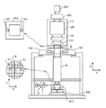
図1は、本発明の1つの実施の形態に係るリソグラフィ装置を模式的に示す。この装置は、放射ビームB(例えば、紫外線(UV)放射や他の適切な放射)を調整する照明システム(イルミネータ)ILと、パターニングデバイス(例えばマスク)MAを支持するよう構成され、第1位置決めデバイスPMに接続されたマスクサポート構造(例えばマスクテーブル)MTと、を含む。第1位置決めデバイスPMは、パターニングデバイスをあるパラメータに従って正確に位置決めする。この装置は、基板(例えばレジストコートウエハ)Wを保持するよう構成され、第2位置決めデバイスPWに接続された基板テーブル(例えばウエハテーブル)WTもしくは「基板サポート」を含む。第2位置決めデバイスPWは、あるパラメータに従って基板を正確に位置決めするよう構成される。この装置はさらに、パターニングデバイスMAによって放射ビームBに付与されたパターンを、基板Wのターゲット部分C(例えば1つもしくは複数のダイを含む)上に投影する投影システム(たとえば屈折投影レンズシステム)PSを含む。 FIG. 1 schematically depicts a lithographic apparatus according to one embodiment of the invention. The apparatus is configured to support an illumination system (illuminator) IL that modulates a radiation beam B (eg, ultraviolet (UV) radiation or other suitable radiation) and a patterning device (eg, mask) MA to provide a first positioning. And a mask support structure (for example, a mask table) MT connected to the device PM. The first positioning device PM accurately positions the patterning device according to certain parameters. The apparatus is configured to hold a substrate (eg, resist coated wafer) W and includes a substrate table (eg, wafer table) WT or “substrate support” connected to a second positioning device PW. The second positioning device PW is configured to accurately position the substrate according to certain parameters. The apparatus further projects a pattern imparted to the radiation beam B by the patterning device MA onto a target portion C (eg including one or more dies) of the substrate W (eg a refractive projection lens system) PS. including.
照明システムは、放射ビームを方向付け、成形し、あるいは制御するために、屈折光学素子、反射光学素子、磁気光学素子、電磁気光学素子、静電光学素子、あるいはこれらの任意の組み合わせなどの様々な種類の光学素子を含んでもよい。 The illumination system can be a variety of refractive optical elements, reflective optical elements, magneto-optical elements, electromagnetic optical elements, electrostatic optical elements, or any combination thereof to direct, shape or control the radiation beam. Various types of optical elements may be included.
マスクサポート構造はパターニングデバイスを支持する、すなわちその重量に耐える。マスクサポート構造は、パターニングデバイスの配向やリソグラフィ装置の設計や、たとえばパターニングデバイスが真空環境中で保持されているか否か等の他の条件などに応じた態様でパターニングデバイスを保持している。マスクサポート構造は、機械的固定、真空固定、静電固定、またはパターニングデバイスを保持するための他の固定用技術を使用できる。マスクサポート構造は、例えば必要に応じて固定または移動させることができるフレームまたはテーブルであってもよい。マスクサポート構造は、パターニングデバイスを例えば投影システムに対して所望の位置に配置することを確実なものとすることができる。本明細書における「レチクル」または「マスク」という用語の使用はすべて、より一般的な「パターニングデバイス」という用語の同義語とみなすことができる。 The mask support structure supports, ie bears the weight of, the patterning device. The mask support structure holds the patterning device in a manner that depends on the orientation of the patterning device, the design of the lithographic apparatus, and other conditions, such as for example whether or not the patterning device is held in a vacuum environment. The mask support structure can use mechanical fixation, vacuum fixation, electrostatic fixation, or other fixation techniques to hold the patterning device. The mask support structure may be, for example, a frame or table that can be fixed or moved as required. The mask support structure may ensure that the patterning device is at a desired position, for example with respect to the projection system. Any use of the terms “reticle” or “mask” herein may be considered synonymous with the more general term “patterning device”.
本明細書で使用されている「パターニングデバイス」という用語は、放射ビームの断面にパターンを付与し、それにより基板のターゲット部分にパターンを生成するべく使用することができる任意のデバイスを意味するものとして広義に解釈されたい。放射ビームに付与されるパターンは、たとえばそのパターンが位相シフトフィーチャまたはいわゆるアシストフィーチャを含んでいる場合、基板のターゲット部分における所望のパターンに必ずしも厳密に対応している必要はないことに留意されたい。放射ビームに付与されるパターンは、通常、ターゲット部分に生成されるデバイス、たとえば集積回路などのデバイス中の特定の機能層に対応している。 As used herein, the term “patterning device” refers to any device that can be used to impart a pattern to a cross-section of a radiation beam, thereby generating a pattern on a target portion of a substrate. Should be interpreted broadly. Note that the pattern imparted to the radiation beam does not necessarily correspond exactly to the desired pattern in the target portion of the substrate, for example if the pattern includes phase shift features or so-called assist features. . The pattern imparted to the radiation beam typically corresponds to a particular functional layer in a device being created in the target portion, such as an integrated circuit.
パターニングデバイスは透過型であっても反射型であってもよい。パターニングデバイスの例としては、例えばマスクやプログラマブルミラーアレイ、プログラマブルLCDパネルなどがある。マスクはリソグラフィの分野では周知であり、バイナリマスクやレベンソン型位相シフトマスク、ハーフトーン型位相シフトマスク、更に各種のハイブリッド型マスクが含まれる。プログラマブルミラーアレイの一例としては、小型のミラーがマトリックス状に配列され、各ミラーが入射してくる放射ビームを異なる方向に反射するように個別に傾斜されるというものがある。これらの傾斜ミラーにより、マトリックス状ミラーで反射された放射ビームにパターンが付与されることになる。 The patterning device may be transmissive or reflective. Examples of patterning devices include masks, programmable mirror arrays, and programmable LCD panels. Masks are well known in the field of lithography, and include binary masks, Levenson phase shift masks, halftone phase shift masks, and various hybrid masks. One example of a programmable mirror array is that small mirrors are arranged in a matrix and each mirror is individually tilted to reflect the incoming radiation beam in different directions. These tilting mirrors impart a pattern to the radiation beam reflected by the matrix mirror.
本明細書で使用されている「投影システム」という用語は、たとえば使用する露光放射に適した、もしくは液浸液の使用または真空の使用などの他の要因に適した、屈折光学系、反射光学系、カタディオプトリック光学系、磁気光学系、電磁気光学系、静電光学系、またはそれらの任意の組合せを含む任意の種類の投影システムが包含されているものとして広義に解釈されたい。本明細書における「投影レンズ」という用語の使用はすべて、より一般的な「投影システム」という用語の同義語とみなすことができる。 As used herein, the term “projection system” refers to refractive optics, reflective optics, eg suitable for the exposure radiation used or other factors such as the use of immersion liquid or the use of a vacuum. It should be construed broadly as encompassing any type of projection system including systems, catadioptric optics, magneto-optics, electromagnetic optics, electrostatic optics, or any combination thereof. Any use of the term “projection lens” herein may be considered as synonymous with the more general term “projection system”.
本明細書に示されるように、本装置は(たとえば透過マスクを用いる)透過型である。あるいはまた、本装置は(たとえば、上述した種類のプログラマブルミラーアレイを用いた、あるいは反射マスクを用いた)反射型であってもよい。 As shown herein, the apparatus is transmissive (eg, using a transmissive mask). Alternatively, the apparatus may be of a reflective type (eg, using a programmable mirror array of the type described above or using a reflective mask).
リソグラフィ装置は2つ以上(2つの場合にはデュアルステージと呼ばれる)の基板テーブルもしくは「基板サポート」(および/または2つ以上のマスクテーブルもしくは「マスクサポート」)を備えてもよい。このような多重ステージ型の装置においては追加されたテーブルまたはサポートは並行して使用されるか、あるいは1以上のテーブルまたはサポートで露光が行われている間に他の1以上のテーブルまたはサポートで準備工程を実行するようにしてもよい。 The lithographic apparatus may comprise two or more (in two cases called dual stage) substrate tables or “substrate supports” (and / or two or more mask tables or “mask supports”). In such a multi-stage apparatus, the added table or support is used in parallel, or at one or more other tables or supports while exposure is being performed on one or more tables or supports. You may make it perform a preparation process.
また、リソグラフィ装置は、基板の少なくとも一部が比較的屈折率の大きい液体、たとえば水で覆われ、それにより投影システムと基板の間の空間が充填されるタイプの装置であってもよい。液浸液はリソグラフィ装置の他の空間、例えばマスクと投影システムとの間に導入されてもよい。液浸技術は、投影システムの開口数を大きくするために使用されうる。本明細書で使用されている「液浸」という用語は、基板などの構造を液体中に浸すべきであることを意味しているのではなく、単に、露光の間、投影システムと基板の間に液体が置かれることを意味しているにすぎない。 The lithographic apparatus may also be of a type wherein at least a portion of the substrate is covered with a liquid having a relatively high refractive index, such as water, thereby filling a space between the projection system and the substrate. An immersion liquid may be introduced into other spaces in the lithographic apparatus, for example, between the mask and the projection system. Immersion techniques can be used to increase the numerical aperture of projection systems. As used herein, the term “immersion” does not mean that a structure, such as a substrate, should be immersed in a liquid, but simply during exposure, between the projection system and the substrate. It just means that the liquid is placed in the.
図1を参照すると、イルミネータILは、放射源SOから放射ビームを受け取っている。例えば放射源がエキシマレーザである場合、放射源およびリソグラフィ装置は、別個の構成要素とすることができる。このような場合、放射ビームは、たとえば適切な誘導ミラーおよび/またはビームエキスパンダを備えたビーム搬送系BDを使用して放射源SOからイルミネータILへ受け渡される。それ以外のたとえば放射源が水銀灯などの場合、放射源はリソグラフィ装置と一体に構成されていてもよい。放射源SOおよびイルミネータILは、またビーム搬送系BDが必要とされる場合にはこれも合わせて、放射システムと称されてもよい。 Referring to FIG. 1, the illuminator IL receives a radiation beam from a radiation source SO. For example, if the radiation source is an excimer laser, the radiation source and the lithographic apparatus may be separate components. In such a case, the radiation beam is passed from the radiation source SO to the illuminator IL using, for example, a beam transport system BD equipped with a suitable guiding mirror and / or beam expander. In other cases the source may be integral with the lithographic apparatus, for example when the source is a mercury lamp. The radiation source SO and the illuminator IL may also be collectively referred to as a radiation system if a beam carrier system BD is required.
イルミネータILは、放射ビームの角強度分布を調整するためのアジャスタADを備えてもよい。一般には、イルミネータの瞳平面における強度分布の少なくとも半径方向外径および/または内径(通常それぞれ「シグマ−アウタ(σ−outer)」、「シグマ−インナ(σ−inner)」と呼ばれる)が調整される。加えて、イルミネータILは、インテグレータINおよびコンデンサCOなどの種々の他の要素を備えてもよい。イルミネータは、ビーム断面における所望の均一性及び強度分布を得るべく放射ビームを調整するために用いられる。 The illuminator IL may include an adjuster AD for adjusting the angular intensity distribution of the radiation beam. Generally, at least the radial outer diameter and / or inner diameter (commonly referred to as “sigma-outer” and “sigma-inner”, respectively) of the intensity distribution in the pupil plane of the illuminator is adjusted. The In addition, the illuminator IL may comprise various other elements such as an integrator IN and a capacitor CO. The illuminator is used to adjust the radiation beam to obtain the desired uniformity and intensity distribution in the beam cross section.
放射ビームBは、マスクサポート構造(例えば、マスクテーブル)MTに保持されたパターニングデバイス(例えば、マスクMA)に入射して、当該パターニングデバイスによりパターンを付与される。マスクMAを透過した後、放射ビームBは、投影システムPSを通過する。投影システムPSは、ビームを基板Wのターゲット部分Cに合焦させる。第2位置決めデバイスPWと位置センサIF(例えば、干渉計、リニアエンコーダ、静電容量センサなど)とにより基板テーブルWTは正確に移動され、例えば放射ビームBの経路に異なる複数のターゲット部分Cをそれぞれ位置決めするように移動される。同じように、第1位置決めデバイスPMともう1つの位置センサ(図1に明確には示されていない)とを用いて、例えばマスクライブラリから機械検索後、または走査中に、マスクMAを放射ビームBの経路に対して正確に位置決めすることができる。通常、マスクテーブルMTの移動は、第1位置決めデバイスPMの一部を形成しているロングストロークモジュール(粗い位置決め用)およびショートストロークモジュール(精細な位置決め用)を使用して実現することができる。同様に、基板テーブルWTもしくは「基板サポート」の移動は、第2位置決め器PWの一部を形成しているロングストロークモジュールおよびショートストロークモジュールを使用して実現することができる。ステッパの場合(スキャナとは対照的に)、マスクテーブルMTは、ショートストロークアクチュエータのみに接続され、あるいは固定される。マスクMAおよび基板Wは、マスクアライメントマークM1、M2および基板アライメントマークP1、P2を使用して整列させることができる。図では、基板アライメントマークは専用のターゲット部分を占有しているが、基板アライメントマークは、ターゲット部分間のスペースに配置されてもよい(このような基板アライメントマークは、スクライブラインアライメントマークとして知られている)。同様に、1つ以上のダイがマスクMA上に設けられる場合、ダイ間にマスクアライメントマークが配置されてもよい。 The radiation beam B is incident on the patterning device (eg, mask MA), which is held on the mask support structure (eg, mask table) MT, and is patterned by the patterning device. After passing through the mask MA, the radiation beam B passes through the projection system PS. The projection system PS focuses the beam on the target portion C of the substrate W. The substrate table WT is accurately moved by the second positioning device PW and the position sensor IF (for example, an interferometer, a linear encoder, a capacitance sensor, etc.), and for example, a plurality of different target portions C are respectively provided in the path of the radiation beam B. Moved to position. Similarly, using a first positioning device PM and another position sensor (not explicitly shown in FIG. 1), for example, after a machine search from a mask library or during a scan, the mask MA is emitted by the radiation beam. It is possible to accurately position with respect to the path B. Usually, the movement of the mask table MT can be realized by using a long stroke module (for coarse positioning) and a short stroke module (for fine positioning) which form a part of the first positioning device PM. Similarly, movement of the substrate table WT or “substrate support” can be achieved using a long stroke module and a short stroke module forming part of the second positioner PW. In the case of a stepper (as opposed to a scanner) the mask table MT is connected or fixed only to the short stroke actuator. Mask MA and substrate W may be aligned using mask alignment marks M1, M2 and substrate alignment marks P1, P2. In the figure, the substrate alignment mark occupies a dedicated target portion, but the substrate alignment mark may be placed in the space between the target portions (such a substrate alignment mark is known as a scribe line alignment mark). ing). Similarly, if more than one die is provided on the mask MA, mask alignment marks may be placed between the dies.
図示の装置は、以下に示すモードのうちの少なくとも1つのモードで使用することができる。
1.ステップモードにおいては、放射ビームに付与されたパターンの全体が1回の照射でターゲット部分Cに投影される間、マスクテーブルMTもしくは「マスクサポート」および基板テーブルWTもしくは「基板サポート」は、実質的に静止状態とされる(すなわち1回の静的な露光)。そして基板テーブルWTもしくは「基板サポート」がX方向及び/またはY方向に移動されて、異なるターゲット部分Cが露光される。ステップモードでは露光フィールドの最大サイズによって、1回の静的露光で結像されるターゲット部分Cの寸法が制限されることになる。
2.スキャンモードにおいては、放射ビームに付与されたパターンがターゲット部分Cに投影される間、マスクテーブルMTもしくは「マスクサポート」および基板テーブルWTもしくは「基板サポート」は、同期して走査される(すなわち1回の動的な露光)。マスクテーブルMTもしくは「マスクサポート」に対する基板テーブルWTもしくは「基板サポート」の速度及び方向は、投影システムPSの拡大(縮小)特性及び像反転特性により定められる。スキャンモードでは露光フィールドの最大サイズが1回の動的露光でのターゲット部分Cの(非走査方向の)幅を制限し、走査移動距離がターゲット部分の(走査方向の)長さを決定する。
3.その他のモードにおいては、マスクテーブルMTもしくは「マスクサポート」はプログラマブルパターニングデバイスを保持して実質的に静止状態とされ、放射ビームに付与されたパターンがターゲット部分Cに投影される間、基板テーブルWTもしくは「基板サポート」が移動またはスキャンされる。このモードでは、通常、パルス放射源が使用され、スキャン中、基板テーブルWTもしくは「基板サポート」が移動する毎に、あるいは連続する放射パルス間に、必要に応じてプログラマブルパターニングデバイスが更新される。この動作モードは、上述したタイプのプログラマブルミラーアレイなどのプログラマブルパターニングデバイスを利用しているマスクレスリソグラフィに容易に適用することができる。
The illustrated apparatus can be used in at least one of the modes shown below.
1. In step mode, the mask table MT or “mask support” and the substrate table WT or “substrate support” are substantially the same while the entire pattern imparted to the radiation beam is projected onto the target portion C in a single exposure. (I.e., one static exposure). The substrate table WT or “substrate support” is then moved in the X and / or Y direction to expose a different target portion C. In the step mode, the size of the target portion C imaged by one static exposure is limited by the maximum size of the exposure field.
2. In scan mode, the mask table MT or “mask support” and the substrate table WT or “substrate support” are scanned synchronously while the pattern imparted to the radiation beam is projected onto the target portion C (
3. In other modes, the mask table MT or “mask support” holds the programmable patterning device and is substantially stationary and the substrate table WT while the pattern imparted to the radiation beam is projected onto the target portion C. Alternatively, the “substrate support” is moved or scanned. In this mode, a pulsed radiation source is typically used, and the programmable patterning device is updated as needed during each scan, either as the substrate table WT or “substrate support” moves, or between successive radiation pulses. This mode of operation can be readily applied to maskless lithography that utilizes programmable patterning device, such as a programmable mirror array of a type as described above.
上述の使用モードの組み合わせおよび/または変形、もしくは全く異なった使用モードが使われてもよい。 Combinations and / or variations on the above described modes of use or entirely different modes of use may also be used.
図2は、総じて参照符号1で示されるアライメント測定システムを示す。このアライメント測定システムは、基板3上のアライメントマーク2の形をとるアライメントターゲットを測定するためのものである。アライメント測定システム1は、基板3に向けて測定ビーム5を提供するためのレーザ源などの照明源4と、基板3で反射された後の測定ビーム5を受けるための検出器システム6と、を備える。
FIG. 2 shows an alignment measurement system indicated generally by the
アライメント測定システム1はさらに、検出器システム6が受けた測定ビーム5に基づいてアライメントを決定する処理ユニット7を備える。
The
照明源4、検出器システム6および/または処理ユニット7は別体であってもよく、または単一のユニットとして統合されていてもよい。処理ユニット7は専用の処理ユニットであってもよく、またはリソグラフィ装置の中央処理ユニットなどのリソグラフィ装置の他のプロセッサに統合されていてもよい。
The
図2の実施の形態では、照明源4は単一の波長を有する連続的測定ビーム5を提供する。測定ビームは45度の角度で偏光している。この角度は例えばアライメントマークにおける小区分方向に対して定義されてもよいし、走査方向やステージ直交方向や他の任意の適切な基準に対して定義されてもよい。
In the embodiment of FIG. 2, the
代替的な実施の形態では、照明源は「白色光」などの複数の波長を含む測定ビームを生成してもよい。すなわち、照明源は可視スペクトルの複数の色の混成を生成してもよい。測定ビーム50は偏光した光線であってもよいし、偏光していない光線であってもよい。測定ビーム4は、パルスビームであってもよいし、連続的なビームであってもよい。
In an alternative embodiment, the illumination source may generate a measurement beam that includes multiple wavelengths, such as “white light”. That is, the illumination source may generate a mixture of multiple colors in the visible spectrum. The measurement beam 50 may be a polarized light beam or an unpolarized light beam. The
検出器システム6は干渉計ユニット8を備える。反射された測定ビーム5は参照ビーム5aと合わされて合成測定ビーム9が生成される。合成測定ビーム9はアライメントマーク2の測定を表す強度変動を有する。アライメント測定システムにおいて使用されるべきそのような干渉計ユニット8はそのようなものとして知られている。
The
合成測定ビーム9はビーム分割デバイス10へと導かれる。ビーム分割デバイス10において、合成測定ビーム9は第1測定ビーム部分9aと第2測定ビーム部分9bとに分けられる。第1測定ビーム部分9aは第1偏光デバイス11に導かれる。第2測定ビーム部分9bは第2偏光デバイス12に導かれる。第1偏光デバイス11から、第1測定ビーム部分9aが第1検出器13に導かれ、第2偏光デバイス12から、第2測定ビーム部分9bが第2検出器14に導かれる。第1検出器13は、第1検出器13によって受け取られた第1測定ビーム部分9aに基づく第1検出信号を提供する。第2検出器14は、第2検出器14によって受け取られた第2測定ビーム部分9bに基づく第2検出信号を提供する。第1、第2検出器13、14によって提供される第1、第2検出信号は、合成測定ビーム9の異なる偏光成分に基づく。
The combined
処理ユニットは、第1検出信号および/または第2検出信号の強度変動に基づいて、アライメントマーク2のアライメントを決定するよう構成される。
The processing unit is configured to determine the alignment of the
測定ビームを異なる偏光を有する2つの測定ビーム部分に分けることの利点は、第1検出信号と第2検出信号との比較によって、例えば第1検出信号と第2検出信号との間の減算によって、アライメントマーク2の層以外の基板上の層によって誘起されたノイズを除去することができることである。このことは図3を参照して説明される。
The advantage of splitting the measurement beam into two measurement beam parts with different polarizations is that the comparison between the first detection signal and the second detection signal, for example by subtraction between the first detection signal and the second detection signal, The noise induced by the layer on the substrate other than the layer of the
図3には、基板3上のいくつかの層20が示される。層20のうちのひとつにアライメントマーク2が設けられる。測定ビームが異なる複数の層20を通過するときまたは層20のうちのひとつで反射されるとき、その測定ビームにノイズが導入されるであろう。測定ビームの異なる複数の偏光角について、このノイズの影響は通常同等である。しかしながら、適切なアライメントマーク2が選択された場合、アライメントマーク2の測定ビームに対する影響は異なる偏光方向について異なるものとなりうる。
In FIG. 3,
検出器13、14によって提供される検出信号は、異なる偏光を有する第1および第2ビーム部分に基づく。これらの検出信号は、処理ユニットにおいて減算などにより比較される。その結果、両方のビーム部分で実質的に同レベルであるノイズレベル、例えば異なる複数の層20に起因するノイズレベルは相殺されるかまたは少なくともかなり低減される。これに対して、第1検出器13および第2検出器14によって受け取られた、異なる偏光を有する2つの測定ビーム部分のアライメントマーク2での反射に起因する強度変動は、異なる値を有するであろう。検出信号を減算することなどによる比較によって検出信号が相殺されるのではなく、アライメントマーク2のアライメントを示す信号が得られるのである。この信号に基づいて、基板のアライメントが決定されうる。
The detection signals provided by the
第1および第2測定ビーム部分の偏光方向は、信号間の最適な差が得られるよう選択されうる。ある実施の形態では、一方の測定ビーム部分は偏光されて磁気的横波(TM波)を伴うビーム部分となる。このTM波は、p波電場を有する、p偏光している、パイ(pi)偏光している、接平面偏光している、などとして示される。他方の測定ビーム部分は偏光されて電気的横波(TE波)を伴うビーム部分となる。このTE波は、s波電場を有する、s偏光している、シグマ偏光している、サジタル面偏光している、などとして示される。 The polarization directions of the first and second measurement beam portions can be selected to obtain an optimal difference between the signals. In one embodiment, one measurement beam portion is polarized into a beam portion with a magnetic transverse wave (TM wave). The TM wave is shown as having a p-wave electric field, p-polarized, pi-polarized, tangentially polarized, etc. The other measurement beam portion is polarized to become a beam portion accompanied by an electrical transverse wave (TE wave). This TE wave is shown as having an s-wave electric field, s-polarized, sigma-polarized, sagittal-polarized, etc.
適切な結果を得るために、2つの偏光間で十分に大きな信号差を提供できる小区分化アライメントマークを使用可能である。ある実施の形態では、そのようなアライメントマーク2は、ある方向において密に小区分化されたラインを、小区分化されていないスペースと組み合わせて含む。
In order to obtain adequate results, sub-segmented alignment marks can be used that can provide a sufficiently large signal difference between the two polarizations. In one embodiment, such an
例えば、所定の位相深さについて、アライメントマークのコントラストは、アライメントマーク2のラインとスペースとの間の反射率(または有効n:Neff)の差によって決定される。小区分化された格子のNeffは、図4に示されるように、小区分化のデューティサイクルを変えると変わる。アライメントマーク2が図4において破線で示されるように、スペースについては0%のデューティサイクル、ラインについては約25%のデューティサイクルとなるよう作られている場合、TM偏光ではアライメント信号はほとんどない。TE偏光についてのアライメント信号は、ラインとスペースとの間の大きな差のためかなり大きい。
For example, for a given phase depth, the alignment mark contrast is determined by the difference in reflectivity (or effective n: Neff) between the line and space of the
図2の実施の形態の別の利点は、光源4のノイズを実質的に排除できることである。照明源4が例えば45度の単一角度で偏光した、所定のノイズレベルを有する光線などの測定ビームを生成する場合、測定ビームは異なる偏光を有する2つの測定ビーム部分に分離されるであろう。したがって、照明源4によって誘起されるどのようなノイズも、第1測定ビーム部分および第2測定ビーム部分の両方について同様のレベルとなるであろう。その結果、第1および第2測定ビーム部分から得られた測定信号の減算または他の比較方法によって、このノイズ項を除去できるかまたは少なくともかなり低減できる。
Another advantage of the embodiment of FIG. 2 is that the noise of the
図5は、本発明に係るアライメント測定システム1の代替的な実施の形態を示す。図2の測定システム1の部分と同じまたは同様な測定システムの部分は同じ符号で示される。
FIG. 5 shows an alternative embodiment of the
アライメント測定システム1は、測定ビーム5を提供するための照明源4と、基板3で、特にアライメントマーク2で反射された後の測定ビーム5を受けるための検出器システム6と、を備える。
The
アライメント測定システム1はさらに、検出器システム6が受けた反射測定ビーム5に基づいてアライメントを決定する処理ユニット7を備える。
The
図5の実施の形態では、照明源4は、パルス白色光レーザ測定ビーム5を提供する。すなわち、照明源4は可視スペクトルの複数の色の混成を提供する。測定ビーム5は、45度の角度で偏光している。この角度は例えばアライメントマークにおける小区分方向に対して定義されてもよいし、走査方向やステージ直交方向に対して定義されてもよい。他の任意の適切な偏光角が使用されてもよい。
In the embodiment of FIG. 5, the
検出器システム6は干渉計ユニット8を備える。反射された測定ビーム5は参照ビーム5aと合わされて合成測定ビーム9が生成される。合成測定ビーム9はアライメントマーク2の測定を表す強度変動を有する。
The
合成測定ビーム9はビーム分割デバイス10へと導かれ、そこで2つの測定ビーム部分9a、9bに分けられる。その後、測定ビーム部分9a、9bのそれぞれは、第1および第2偏光デバイス11、12のうちのひとつへと導かれる。
The combined
第1測定ビーム部分9aは第1分散ファイバ31によって受け取られ、第2測定ビーム部分9bは第2分散ファイバ32によって受け取られる。第1分散ファイバ31は第1検出器13につながっており、第2分散ファイバ32は第2検出器14につながっている。分散ファイバ31、32の長さに起因して、パルス光の異なる波長は時間的に分離される。この効果のさらなる詳細については、ネイチャー(Nature)、458巻、2009年、1145頁−1150頁を参照されたい。これは参照により本明細書に組み入れられる。その結果、異なる波長の強度変動は、第1検出器13および第2検出器14に、異なる時刻に到達する。照明源4の最初の測定ビームパルス後の適切な時間を選択することにより、第1検出器13および第2検出器14によって受信された測定強度と波長とを対応付けることができる。このようにして、測定ビーム5の異なる波長についての強度変動応答が得られる。
The first
正しい波長と最初のパルス後の正しい時間とを対応付けるために、アライメント測定システム1は較正されるべきである。そのような較正は、パルスが照明源4によって放たれた後、所定の波長が第1または第2検出器13、14に到着するのに必要な時間を決定することによって行われうる。
In order to associate the correct wavelength with the correct time after the first pulse, the
処理ユニット7において、第1検出器および第2検出器の信号の強度を時間の関数として解析するために、ボックスカー積分機能を使用してもよい。そのようなボックスカー積分機能方法は知られている。
In the
図5の実施の形態の利点は、白色光の単一パルスの異なる複数の波長を、単一の検出器13、14によって解析できることである。検出器13、14によって受け取られる強度の時間変動は、波長の関数である。処理ユニットにおける適切な処理によって、照明源の単一のパルスで、アライメントマークの全ての波長−偏光依存反射率を得ることができる。これにより、より役に立つアライメント情報を得ることができ、したがって、処理ロバストなアライメント位置を改善することができる。
An advantage of the embodiment of FIG. 5 is that different wavelengths of a single pulse of white light can be analyzed by a
分散ファイバおよび分散ファイバに伴う上述の効果を一般のアライメント測定システムにも適用できることを注意しておく。そのようなアライメント測定システムでは、合成測定ビーム9は2つ以上の測定ビーム部分9a、9bに分割されることはない。そのようなシステムでは、合成測定ビーム9を分散ファイバを通じて導くことで、異なる波長の強度変動を分散させ、これらの強度を単一の検出器によって時間したがって波長に依存して測定することができる。
It should be noted that the above-described effects associated with dispersion fibers and dispersion fibers can be applied to general alignment measurement systems. In such an alignment measurement system, the combined
さらに、図5の実施の形態は、測定ビームを異なる偏光を有する2つの測定ビーム部分に分け、その2つの測定ビーム部分から得られる検出信号を減算するなどして比較することにより、ノイズを低減または相殺できるという利点を有する。このノイズは、照明源4に起因するノイズまたは基板3上の異なる複数の層20に起因するノイズの両方であってもよい。
Furthermore, the embodiment of FIG. 5 reduces the noise by dividing the measurement beam into two measurement beam portions having different polarizations and comparing them by subtracting the detection signals obtained from the two measurement beam portions. Or it has the advantage that it can be offset. This noise may be both noise due to the
本明細書ではICの製造におけるリソグラフィ装置の使用を例として説明しているが、リソグラフィ装置は他の用途にも適用することが可能であるものと理解されたい。他の用途としては、集積光学システム、磁区メモリ用ガイダンスおよび検出パターン、フラットパネルディスプレイ、液晶ディスプレイ(LCD)、薄膜磁気ヘッドなどがある。当業者であればこれらの他の適用に際して、本明細書における「ウエハ」あるいは「ダイ」という用語がそれぞれ「基板」あるいは「ターゲット部分」という、より一般的な用語と同義であるとみなされると理解することができるであろう。基板は露光前または露光後においてトラック(典型的にはレジスト層を基板に塗布し、露光後のレジストを現像する装置)、メトロロジツール、及び/またはインスペクションツールにより処理されてもよい。適用可能であれば、本明細書の開示はこれらのまたは他の基板処理装置にも適用され得る。また、基板は例えば多層ICを製造するために複数回処理されてもよく、その場合には本明細書における基板という用語は既に処理されている多数の処理層を含む基板をも意味する。 Although the use of a lithographic apparatus in the manufacture of an IC is described herein as an example, it should be understood that the lithographic apparatus can be applied to other applications. Other applications include integrated optical systems, magnetic domain memory guidance and detection patterns, flat panel displays, liquid crystal displays (LCDs), thin film magnetic heads, and the like. For those other applications, those skilled in the art will consider that the terms "wafer" or "die" herein are considered synonymous with the more general terms "substrate" or "target portion", respectively. Will be able to understand. The substrate may be processed by a track (typically an apparatus for applying a resist layer to the substrate and developing the exposed resist), metrology tool, and / or inspection tool before or after exposure. Where applicable, the disclosure herein may be applied to these or other substrate processing apparatus. The substrate may also be processed multiple times, for example to produce a multi-layer IC, in which case the term substrate herein also means a substrate comprising a number of processing layers that have already been processed.
ここでは特に光リソグラフィを本発明に係る実施の形態に適用したものを例として説明しているが、本発明は例えばインプリントリソグラフィなど文脈が許す限り他にも適用可能であり、光リソグラフィに限られるものではない。インプリントリソグラフィでは、パターニングデバイスのトポグラフィが基板に生成されるパターンを決める。パターニングデバイスのトポグラフィが基板に塗布されているレジスト層に押し付けられ、電磁放射や熱、圧力、あるいはこれらの組み合わせによってレジストが硬化される。レジストが硬化されてから、パターニングデバイスは、パターンが生成されたレジストから外されて外部に移動される。 Here, an example in which photolithography is applied to the embodiment according to the present invention is described as an example, but the present invention can be applied to other cases as the context permits, such as imprint lithography. Is not something In imprint lithography, the topography of the patterning device determines the pattern that is generated on the substrate. The topography of the patterning device is pressed against the resist layer applied to the substrate, and the resist is cured by electromagnetic radiation, heat, pressure, or a combination thereof. After the resist is cured, the patterning device is moved out of the resist from which the pattern was generated.
本明細書において「放射」および「ビーム」という用語は、紫外(UV)放射(例えば約365nm、248nm、193nm、157nm、または126nmの波長を有する)および極端紫外(EUV)放射(例えば5nm−20nmの範囲の波長を有する)を含むあらゆる種類の電磁放射、およびイオンビームや電子ビームなどの粒子線を示す。 As used herein, the terms “radiation” and “beam” refer to ultraviolet (UV) radiation (eg, having a wavelength of about 365 nm, 248 nm, 193 nm, 157 nm, or 126 nm) and extreme ultraviolet (EUV) radiation (eg, 5 nm-20 nm). All types of electromagnetic radiation (including having a wavelength in the range) and particle beams such as ion beams and electron beams.
「レンズ」という用語は、文脈が許す限り、屈折光学素子、反射光学素子、磁気的光学素子、電磁気的光学素子、静電的光学素子を含む1つまたは各種の光学素子の組み合わせを指し示すものであってもよい。 The term “lens” refers to one or a combination of various optical elements including refractive optical elements, reflective optical elements, magnetic optical elements, electromagnetic optical elements, electrostatic optical elements, as the context allows. There may be.
本発明の具体的な実施の形態が上述のように説明されたが、本発明は上述の形式以外の形式でも実施可能であると理解されたい。例えば、本発明はコンピュータプログラムの形式を取ってもよい。このコンピュータプログラムは機械に読み取り可能な命令の1つもしくは複数のシーケンスを含む。命令は、上述の方法を記述する。あるいはまた、本発明は、そのようなコンピュータプログラムを記憶保持するデータ記憶媒体(例えば半導体メモリ、磁気もしくは光学ディスク)の形式を取ってもよい。 While specific embodiments of the invention have been described above, it will be appreciated that the invention may be practiced otherwise than as described. For example, the present invention may take the form of a computer program. The computer program includes one or more sequences of machine readable instructions. The instruction describes the method described above. Alternatively, the present invention may take the form of a data storage medium (eg, semiconductor memory, magnetic or optical disk) that stores and holds such computer programs.
上述の記載は例示を目的としており、それに限定されるものではない。したがって下記の実施の形態の範囲から逸脱することなく記載された発明に変更を加えることができるということは、関連技術の当業者には明らかなことであろう。
1.対象上のアライメントターゲットを測定するためのアライメント測定システムであって、
対象に向けて測定ビームを提供する照明源と、
対象で反射した後の測定ビームを受ける検出器システムと、
検出器システムが受けた測定ビームに基づいてアライメントを決定する処理ユニットと、を備え、
本測定システムは、
測定ビームを第1ビーム部分と第2ビーム部分とに分けるビーム分割デバイスと、
第1ビーム部分および/または第2ビーム部分を偏光させるかまたはその偏光を変える偏光デバイスと、を備え、
結果として得られる第1ビーム部分の偏光角は結果として得られる第2ビーム部分の偏光角とは異なり、
検出器システムは、第1ビーム部分を受ける第1検出器と第2ビーム部分を受ける第2検出器とを含み、
処理ユニットは、偏光した第1ビーム部分と偏光した第2ビーム部分との比較を含む信号に基づいてアライメントを決定するよう構成される、アライメント測定システム。
2.照明源は偏光した測定ビームを提供するよう構成される、実施の形態1に記載のシステム。
3.照明源は複数の波長を含む測定ビームを提供する、実施の形態1に記載のシステム。
4.照明源は単一の波長を有する測定ビームを提供する、実施の形態1に記載のシステム。
5.照明源はパルス状の測定ビームを提供する、実施の形態1に記載のシステム。
6.偏光デバイスは、第1ビーム部分を偏光させるかまたはその偏光を変える第1偏光デバイスと、第2ビーム部分を偏光させるかまたはその偏光を変える第2偏光デバイスと、を含む、実施の形態1に記載のシステム。
7.検出器システムは干渉デバイスを含む、実施の形態1に記載のシステム。
8.検出器システムは第1および第2ビーム部分のそれぞれについて、ビーム分割デバイスと対応する検出器との間に分散ファイバを備える、実施の形態1に記載のシステム。
9.第1検出器、第2検出器はそれぞれ、第1ビーム部分、第2ビーム部分の強度を測定するよう構成されている、実施の形態8に記載のシステム。
10.比較は、第2検出器によって測定された強度を第1検出器によって測定された強度から減算することを含む、実施の形態9に記載のシステム。
11.放射ビームを調整するよう構成された照明システムと、
放射ビームの断面にパターンを付与することでパターン付与された放射ビームを形成可能なパターニングデバイスを支持するよう構成されたサポートと、
基板を保持するよう構成された基板テーブルと、
パターン付与された放射ビームを基板のターゲット部分に投影するよう構成された投影システムと、を備え、
本リソグラフィ装置は実施の形態1から11のいずれかに記載のアライメント測定システムを備える、リソグラフィ装置。
12.リソグラフィ装置において基板のアライメントを決定する方法であって、
照明源によって、基板上のアライメントターゲットを測定ビームで照明することと、
検出器システムによって、対象で反射した後の測定ビームを受けることと、
処理ユニットアライメントによって、検出器システムが受けた測定ビームに基づいて、基板のアライメントを決定することと、を含み、
本方法は、
ビーム分割デバイスによって、測定ビームを第1ビーム部分と第2ビーム部分とに分けることと、
第1および/または第2偏光デバイスによって、第1ビーム部分および/または第2ビーム部分を偏光させるかまたはその偏光を変えることと、を含み、
結果として得られる第1ビーム部分の偏光角は結果として得られる第2ビーム部分の偏光角とは異なり、
アライメントを決定するステップは、第1ビーム部分に基づく第1測定信号と第2ビーム部分に基づく第2測定信号との比較に基づく、方法。
13.第1および第2ビーム部分間の信号差を増やすために、アライメントターゲットは小区分化されている、実施の形態12に記載の方法。
14.アライメントマークはラインとスペースとを有し、ラインは小区分化されている、実施の形態13に記載の方法。
15.第1放射は高い繰り返しレートを有する高い強度の短パルス放射である、実施の形態12に記載の方法。
16.対象上のアライメントターゲットを測定するためのアライメント測定システムであって、
複数の波長の光を含む測定ビームパルスを対象に向けて提供する照明源と、
対象で反射した後の測定ビームパルスを受ける検出器システムと、
検出器システムが受けた測定ビームパルスに基づいてアライメントを決定する処理ユニットと、を備え、
検出器システムは第1検出器および分散ファイバを含み、
前記測定ビームパルスの異なる波長成分が前記分散ファイバのなかで分光されて第1検出器に異なる時刻に到達するよう、分散ファイバは測定ビームパルスの少なくとも一部を第1検出器へ案内するよう構成される、アライメント測定システム。
17.放射ビームを調整するよう構成された照明システムと、
放射ビームの断面にパターンを付与することでパターン付与された放射ビームを形成可能なパターニングデバイスを支持するよう構成されたサポートと、
基板を保持するよう構成された基板テーブルと、
パターン付与された放射ビームを基板のターゲット部分に投影するよう構成された投影システムと、を備え、
本リソグラフィ装置は対象上のアライメントターゲットを測定するためのアライメント測定システムを備え、
アライメント測定システムは、
複数の波長の光を含む測定ビームパルスを対象に向けて提供する照明源と、
対象で反射した後の測定ビームパルスを受ける検出器システムと、
検出器システムが受けた測定ビームパルスに基づいてアライメントを決定する処理ユニットと、を備え、
検出器システムは第1検出器および分散ファイバを含み、
前記測定ビームパルスの異なる波長成分が前記分散ファイバのなかで分光されて第1検出器に異なる時刻に到達するよう、分散ファイバは測定ビームパルスの少なくとも一部を第1検出器へ案内するよう構成される、リソグラフィ装置。
18.リソグラフィ装置において基板のアライメントを決定する方法であって、
照明源によって、複数の波長の光を含む測定ビームパルスで基板上のアライメントターゲットを照明することと、
検出器システムによって、対象で反射した後の測定ビームパルスを受けることとと、
処理ユニットによって、検出器システムが受けた測定ビームパルスに基づいてアライメントを決定することと、を含み、
前記検出器システムによって前記測定ビームパルスを受けるステップは、
前記測定ビームパルスの異なる波長成分が分散ファイバのなかで分光されて第1検出器に異なる時刻に到達するよう、前記分散ファイバを通じて測定ビームパルスの少なくとも一部を検出器システムの第1検出器へ案内することを含む、方法。
The above description is intended to be illustrative and not limiting. Accordingly, it will be apparent to those skilled in the relevant art that modifications can be made to the invention described without departing from the scope of the following embodiments.
1. An alignment measurement system for measuring an alignment target on an object,
An illumination source that provides a measurement beam toward the object;
A detector system that receives the measurement beam after reflection at the object;
A processing unit for determining alignment based on a measurement beam received by the detector system,
This measurement system
A beam splitting device that splits the measurement beam into a first beam portion and a second beam portion;
A polarization device that polarizes or changes the polarization of the first beam portion and / or the second beam portion,
The resulting polarization angle of the first beam portion is different from the resulting polarization angle of the second beam portion,
The detector system includes a first detector that receives the first beam portion and a second detector that receives the second beam portion;
The alignment measurement system, wherein the processing unit is configured to determine alignment based on a signal that includes a comparison of the polarized first beam portion and the polarized second beam portion.
2. The system of
3. The system of
4). The system of
5. The system of
6). The polarization device includes: a first polarization device that polarizes or changes the polarization of the first beam portion; and a second polarization device that polarizes or changes the polarization of the second beam portion. The described system.
7). The system of
8). The system of
9. The system of
10. The system of
11. An illumination system configured to condition the radiation beam;
A support configured to support a patterning device capable of forming a patterned radiation beam by applying a pattern to a cross section of the radiation beam;
A substrate table configured to hold a substrate;
A projection system configured to project a patterned beam of radiation onto a target portion of a substrate;
A lithographic apparatus, comprising the alignment measurement system according to any one of the first to eleventh embodiments.
12 A method for determining alignment of a substrate in a lithographic apparatus, comprising:
Illuminating the alignment target on the substrate with a measurement beam by an illumination source;
Receiving a measurement beam after being reflected off the object by a detector system;
Determining, by processing unit alignment, the alignment of the substrate based on the measurement beam received by the detector system;
This method
Separating the measurement beam into a first beam portion and a second beam portion by means of a beam splitting device;
Polarizing or changing the polarization of the first beam portion and / or the second beam portion with a first and / or second polarizing device;
The resulting polarization angle of the first beam portion is different from the resulting polarization angle of the second beam portion,
The method of determining alignment is based on a comparison of a first measurement signal based on the first beam portion and a second measurement signal based on the second beam portion.
13. The method of
14 The method according to
15. 13. The method of
16. An alignment measurement system for measuring an alignment target on an object,
An illumination source that provides a measurement beam pulse including multiple wavelengths of light toward an object;
A detector system that receives a measurement beam pulse after reflection at the object;
A processing unit for determining alignment based on measurement beam pulses received by the detector system,
The detector system includes a first detector and a dispersion fiber;
The dispersion fiber is configured to guide at least a portion of the measurement beam pulse to the first detector so that different wavelength components of the measurement beam pulse are dispersed in the dispersion fiber and reach the first detector at different times. An alignment measurement system.
17. An illumination system configured to condition the radiation beam;
A support configured to support a patterning device capable of forming a patterned radiation beam by applying a pattern to a cross section of the radiation beam;
A substrate table configured to hold a substrate;
A projection system configured to project a patterned beam of radiation onto a target portion of a substrate;
The lithographic apparatus comprises an alignment measurement system for measuring an alignment target on the object,
The alignment measurement system
An illumination source that provides a measurement beam pulse including multiple wavelengths of light toward an object;
A detector system that receives a measurement beam pulse after reflection at the object;
A processing unit for determining alignment based on measurement beam pulses received by the detector system,
The detector system includes a first detector and a dispersion fiber;
The dispersion fiber is configured to guide at least a portion of the measurement beam pulse to the first detector so that different wavelength components of the measurement beam pulse are dispersed in the dispersion fiber and reach the first detector at different times. A lithographic apparatus.
18. A method for determining alignment of a substrate in a lithographic apparatus, comprising:
Illuminating an alignment target on the substrate with a measurement beam pulse comprising light of multiple wavelengths by an illumination source;
Receiving a measurement beam pulse after being reflected off the object by a detector system;
Determining an alignment by a processing unit based on a measurement beam pulse received by the detector system;
Receiving the measurement beam pulse by the detector system comprises:
At least a portion of the measurement beam pulse is passed through the dispersion fiber to the first detector of the detector system so that different wavelength components of the measurement beam pulse are dispersed in the dispersion fiber and reach the first detector at different times. A method comprising guiding.
Claims (4)
対象に向けて複数の波長の光を含む測定ビームパルスを提供する照明源と、
対象で反射した後の測定ビームパルスの異なる偏光成分間の差を検出する検出器システムと、
検出器システムによって検出された差に基づいてアライメントを決定する処理ユニットと、を備え、
前記検出器システムは、検出器および分散ファイバを含み、前記測定ビームパルスの異なる波長成分が前記分散ファイバのなかで分光されて前記検出器に異なる時刻に到達するよう、前記分散ファイバは前記測定ビームパルスの少なくとも一部を前記検出器へ案内するよう構成され、
前記処理ユニットは、前記測定ビームパルスの異なる波長についての強度変動応答を得るために、最初の測定ビームパルス後の適切な時間を選択することにより、前記検出器によって受信された測定強度と各波長とを対応付ける、アライメント測定システム。 An alignment measurement system for measuring an alignment target on an object,
An illumination source that provides a measurement beam pulse that includes multiple wavelengths of light toward an object
A detector system for detecting the difference between the different polarization components of the measurement beam pulse after reflection at the object;
A processing unit for determining alignment based on the difference detected by the detector system ,
The detector system includes a detector and a dispersion fiber, wherein the dispersion fiber is the measurement beam so that different wavelength components of the measurement beam pulse are dispersed in the dispersion fiber to reach the detector at different times. Configured to guide at least a portion of a pulse to the detector;
The processing unit selects the appropriate time after the first measurement beam pulse to obtain an intensity variation response for different wavelengths of the measurement beam pulse, so that the measured intensity received by the detector and each wavelength associating the door, alignment measurement system.
放射ビームの断面にパターンを付与することでパターン付与された放射ビームを形成可能なパターニングデバイスを支持するよう構成されたサポートと、
基板を保持するよう構成された基板テーブルと、
パターン付与された放射ビームを基板のターゲット部分に投影するよう構成された投影システムと、を備え、
本リソグラフィ装置は請求項1または2に記載のアライメント測定システムを備える、リソグラフィ装置。 An illumination system configured to condition the radiation beam;
A support configured to support a patterning device capable of forming a patterned radiation beam by applying a pattern to a cross section of the radiation beam;
A substrate table configured to hold a substrate;
A projection system configured to project a patterned beam of radiation onto a target portion of a substrate;
This lithographic apparatus comprises an alignment measuring system according to claim 1 or 2, the lithographic apparatus.
照明源によって、基板上のアライメントターゲットを複数の波長の光を含む測定ビームパルスで照明することと、
検出器システムによって、対象で反射した後の測定ビームパルスの異なる偏光成分間の差を検出することと、
処理ユニットによって、検出器システムが検出した差に基づいて、基板のアライメントを決定することと、を含み、
前記検出器システムは、検出器および分散ファイバを含み、
前記検出器システムによる検出ステップは、前記測定ビームパルスの異なる波長成分が前記分散ファイバのなかで分光されて前記検出器に異なる時刻に到達するよう、前記分散ファイバを通じて前記測定ビームパルスの少なくとも一部を前記検出器へ案内することを含み、
前記処理ユニットによる決定ステップは、前記測定ビームパルスの異なる波長についての強度変動応答を得るために、最初の測定ビームパルス後の適切な時間を選択することにより、前記検出器によって受信された測定強度と各波長とを対応付けることを含む、方法。 A method for determining alignment of a substrate in a lithographic apparatus, comprising:
Illuminating an alignment target on the substrate with an illumination source with a measurement beam pulse comprising light of multiple wavelengths ;
Detecting a difference between different polarization components of the measurement beam pulse after being reflected by the object by means of a detector system;
By the processing unit, on the basis of the difference detector system detects, see containing and determining an alignment of the substrate, and
The detector system includes a detector and a dispersion fiber;
The detection step by the detector system comprises at least part of the measurement beam pulse through the dispersion fiber so that different wavelength components of the measurement beam pulse are dispersed in the dispersion fiber and reach the detector at different times. Guiding the detector to the detector,
The determining step by the processing unit comprises measuring intensity received by the detector by selecting an appropriate time after the first measuring beam pulse to obtain an intensity variation response for different wavelengths of the measuring beam pulse. And associating each wavelength with each other .
Applications Claiming Priority (2)
| Application Number | Priority Date | Filing Date | Title |
|---|---|---|---|
| US38214710P | 2010-09-13 | 2010-09-13 | |
| US61/382,147 | 2010-09-13 |
Related Child Applications (1)
| Application Number | Title | Priority Date | Filing Date |
|---|---|---|---|
| JP2014079408A Division JP2014132695A (en) | 2010-09-13 | 2014-04-08 | Alignment determination system, lithography apparatus, and method of determining alignment in lithography apparatus |
Publications (2)
| Publication Number | Publication Date |
|---|---|
| JP2012060131A JP2012060131A (en) | 2012-03-22 |
| JP5559114B2 true JP5559114B2 (en) | 2014-07-23 |
Family
ID=45806404
Family Applications (2)
| Application Number | Title | Priority Date | Filing Date |
|---|---|---|---|
| JP2011196769A Active JP5559114B2 (en) | 2010-09-13 | 2011-09-09 | Alignment measurement system, lithographic apparatus, and method for determining alignment in a lithographic apparatus |
| JP2014079408A Pending JP2014132695A (en) | 2010-09-13 | 2014-04-08 | Alignment determination system, lithography apparatus, and method of determining alignment in lithography apparatus |
Family Applications After (1)
| Application Number | Title | Priority Date | Filing Date |
|---|---|---|---|
| JP2014079408A Pending JP2014132695A (en) | 2010-09-13 | 2014-04-08 | Alignment determination system, lithography apparatus, and method of determining alignment in lithography apparatus |
Country Status (3)
| Country | Link |
|---|---|
| US (2) | US9046385B2 (en) |
| JP (2) | JP5559114B2 (en) |
| NL (1) | NL2007177A (en) |
Families Citing this family (15)
| Publication number | Priority date | Publication date | Assignee | Title |
|---|---|---|---|---|
| NL2007177A (en) | 2010-09-13 | 2012-03-14 | Asml Netherlands Bv | Alignment measurement system, lithographic apparatus, and a method to determine alignment of in a lithographic apparatus. |
| NL2011477A (en) | 2012-10-10 | 2014-04-14 | Asml Netherlands Bv | Mark position measuring apparatus and method, lithographic apparatus and device manufacturing method. |
| US9939742B2 (en) | 2012-11-05 | 2018-04-10 | Asml Netherlands B.V. | Method and apparatus for measuring asymmetry of a microstructure, position measuring method, position measuring apparatus, lithographic apparatus and device manufacturing method |
| US8830456B2 (en) * | 2013-02-01 | 2014-09-09 | Zeta Instruments, Inc. | Optical inspector |
| US9383661B2 (en) | 2013-08-10 | 2016-07-05 | Kla-Tencor Corporation | Methods and apparatus for determining focus |
| US10935893B2 (en) * | 2013-08-11 | 2021-03-02 | Kla-Tencor Corporation | Differential methods and apparatus for metrology of semiconductor targets |
| CN106415193B (en) * | 2014-03-21 | 2019-08-09 | 卡尔佩迪姆技术有限公司 | System and method for manufacturing microstructure on flexible substrates |
| WO2017009036A1 (en) | 2015-07-13 | 2017-01-19 | Asml Netherlands B.V. | Lithographic apparatus and device manufacturing method |
| WO2017032534A2 (en) | 2015-08-27 | 2017-03-02 | Asml Netherlands B.V. | Lithographic apparatus and device manufacturing method |
| CN106610570B (en) * | 2015-10-21 | 2020-11-13 | 上海微电子装备(集团)股份有限公司 | Device and method for realizing positioning of motion platform |
| CN109313402B (en) * | 2016-06-03 | 2020-08-28 | Asml控股股份有限公司 | Alignment system wafer stack beam analyzer |
| US10788766B2 (en) | 2017-05-08 | 2020-09-29 | Asml Netherlands B.V. | Metrology sensor, lithographic apparatus and method for manufacturing devices |
| CN110637258A (en) * | 2017-05-15 | 2019-12-31 | Asml荷兰有限公司 | Metrology sensor for manufacturing a device, lithographic apparatus and method |
| NL2022852A (en) | 2018-04-26 | 2019-10-31 | Asml Holding Nv | Alignment sensor apparatus for process sensivity compensation |
| WO2020169357A1 (en) * | 2019-02-21 | 2020-08-27 | Asml Holding N.V. | Wafer alignment using form birefringence of targets or product |
Family Cites Families (24)
| Publication number | Priority date | Publication date | Assignee | Title |
|---|---|---|---|---|
| JPS62211503A (en) | 1986-03-13 | 1987-09-17 | Hitachi Ltd | Step measuring instrument |
| JPS635203A (en) | 1986-06-25 | 1988-01-11 | Hitachi Ltd | Method and apparatus for detecting pattern |
| US5182610A (en) | 1990-04-19 | 1993-01-26 | Sortec Corporation | Position detecting method and device therefor as well as aligning device |
| JPH0635928B2 (en) | 1990-10-11 | 1994-05-11 | 株式会社ソルテック | Position detection method and position alignment method |
| JPH0540026A (en) | 1991-03-15 | 1993-02-19 | Nippon Seiko Kk | Pattern reading device |
| JPH0587528A (en) | 1991-09-27 | 1993-04-06 | Canon Inc | Method and device for measuring optical heterodyne interference |
| JPH07239212A (en) | 1994-02-28 | 1995-09-12 | Nikon Corp | Position detector |
| JPH09293663A (en) | 1996-04-26 | 1997-11-11 | Nikon Corp | Position detecting device and aligner provided with this device |
| US20010026357A1 (en) | 1996-04-26 | 2001-10-04 | Nikon Corporation | Position transducer and exposure apparatus with same |
| US6606159B1 (en) | 1999-08-02 | 2003-08-12 | Zetetic Institute | Optical storage system based on scanning interferometric near-field confocal microscopy |
| JP2003506741A (en) | 1999-08-02 | 2003-02-18 | ゼテティック・インスティチュート | Scanning interferometer near-field confocal microscope |
| US6891627B1 (en) * | 2000-09-20 | 2005-05-10 | Kla-Tencor Technologies Corp. | Methods and systems for determining a critical dimension and overlay of a specimen |
| JP2002350117A (en) | 2001-05-29 | 2002-12-04 | Olympus Optical Co Ltd | Apparatus and method for measuring shape |
| JP2005509147A (en) * | 2001-11-05 | 2005-04-07 | ザイゴ コーポレーション | Interference period error compensation |
| TWI229243B (en) | 2002-09-20 | 2005-03-11 | Asml Netherlands Bv | Lithographic marker structure, lithographic projection apparatus comprising such a lithographic marker structure and method for substrate alignment using such a lithographic marker structure |
| JP2005062155A (en) * | 2003-07-25 | 2005-03-10 | Olympus Corp | Coherent raman scattering microscope |
| US7136163B2 (en) * | 2003-12-09 | 2006-11-14 | Applied Materials, Inc. | Differential evaluation of adjacent regions for change in reflectivity |
| US20060117293A1 (en) | 2004-11-30 | 2006-06-01 | Nigel Smith | Method for designing an overlay mark |
| EP1839037B1 (en) | 2005-01-16 | 2013-10-30 | Stephen C. Baer | Single wavelength stimulated emission depletion microscopy |
| US7642536B2 (en) | 2005-01-16 | 2010-01-05 | Baer Stephen C | Real-time high-magnification stereoscopic microscope |
| US7701577B2 (en) * | 2007-02-21 | 2010-04-20 | Asml Netherlands B.V. | Inspection method and apparatus, lithographic apparatus, lithographic processing cell and device manufacturing method |
| ES2537333T3 (en) * | 2008-07-24 | 2015-06-05 | The Regents Of The University Of California | Apparatus and procedure for imaging using the dispersive Fourier transform |
| JP4436878B2 (en) | 2008-10-06 | 2010-03-24 | オリンパス株式会社 | Apparatus for detecting physical quantity of observation object and detection method using the same |
| NL2007177A (en) | 2010-09-13 | 2012-03-14 | Asml Netherlands Bv | Alignment measurement system, lithographic apparatus, and a method to determine alignment of in a lithographic apparatus. |
-
2011
- 2011-07-26 NL NL2007177A patent/NL2007177A/en not_active Application Discontinuation
- 2011-08-10 US US13/206,592 patent/US9046385B2/en active Active
- 2011-09-09 JP JP2011196769A patent/JP5559114B2/en active Active
-
2014
- 2014-04-08 JP JP2014079408A patent/JP2014132695A/en active Pending
-
2015
- 2015-05-29 US US14/725,023 patent/US9280057B2/en active Active
Also Published As
| Publication number | Publication date |
|---|---|
| US20150261100A1 (en) | 2015-09-17 |
| NL2007177A (en) | 2012-03-14 |
| US9280057B2 (en) | 2016-03-08 |
| JP2014132695A (en) | 2014-07-17 |
| JP2012060131A (en) | 2012-03-22 |
| US20120062863A1 (en) | 2012-03-15 |
| US9046385B2 (en) | 2015-06-02 |
Similar Documents
| Publication | Publication Date | Title |
|---|---|---|
| JP5559114B2 (en) | Alignment measurement system, lithographic apparatus, and method for determining alignment in a lithographic apparatus | |
| KR101357081B1 (en) | Overlay measurement apparatus, lithographic apparatus, and device manufacturing method using such overlay measurement apparatus | |
| JP5027731B2 (en) | Inspection method and apparatus, lithographic apparatus, lithographic processing cell and device manufacturing method | |
| JP6181284B2 (en) | Method for measuring asymmetry of microstructure and measuring apparatus, position measuring method, position measuring apparatus, lithographic apparatus and device manufacturing method | |
| JP5300181B2 (en) | Measurement apparatus, lithographic apparatus, process apparatus, measurement method, and device manufacturing method. | |
| CN101089733B (en) | A method of characterising the transmission losses of an optical system | |
| JP4971225B2 (en) | Method for measuring asymmetry of scatterometer, method for measuring overlay error of substrate, and measuring apparatus | |
| JP5323875B2 (en) | Lithographic apparatus and device manufacturing method | |
| US7480050B2 (en) | Lithographic system, sensor, and method of measuring properties of a substrate | |
| KR20120026020A (en) | Self-referencing interferometer, alignment system, and lithographic apparatus | |
| JP2009002931A (en) | Method of forming substrate for use in calibrating metrology tool, calibration substrate, and metrology tool calibration method | |
| US20080036984A1 (en) | Method and apparatus for angular-resolved spectroscopic lithography characterization | |
| JP2012526402A (en) | How to determine overlay errors | |
| JP2008277754A (en) | Inspection method, device manufacturing method, inspection apparatus, substrate, mask, lithography apparatus, and lithography cell | |
| JP2008139303A (en) | Inspection method and apparatus, lithographic apparatus, lithographic processing cell, and device manufacturing method | |
| CN114008534A (en) | Metrology method and associated metrology and lithographic apparatus | |
| US10514620B2 (en) | Alignment method | |
| JP4643627B2 (en) | Focus test execution method and device manufacturing method | |
| CN112639623A (en) | Apparatus and method for measuring position of alignment mark | |
| JP6817468B2 (en) | Sensors, lithography equipment, and device manufacturing methods | |
| US10942461B2 (en) | Alignment measurement system |
Legal Events
| Date | Code | Title | Description |
|---|---|---|---|
| A977 | Report on retrieval |
Free format text: JAPANESE INTERMEDIATE CODE: A971007 Effective date: 20121217 |
|
| A131 | Notification of reasons for refusal |
Free format text: JAPANESE INTERMEDIATE CODE: A131 Effective date: 20130108 |
|
| A521 | Request for written amendment filed |
Free format text: JAPANESE INTERMEDIATE CODE: A523 Effective date: 20130405 |
|
| A131 | Notification of reasons for refusal |
Free format text: JAPANESE INTERMEDIATE CODE: A131 Effective date: 20131008 |
|
| A601 | Written request for extension of time |
Free format text: JAPANESE INTERMEDIATE CODE: A601 Effective date: 20131227 |
|
| A602 | Written permission of extension of time |
Free format text: JAPANESE INTERMEDIATE CODE: A602 Effective date: 20140108 |
|
| A521 | Request for written amendment filed |
Free format text: JAPANESE INTERMEDIATE CODE: A523 Effective date: 20140408 |
|
| TRDD | Decision of grant or rejection written | ||
| A01 | Written decision to grant a patent or to grant a registration (utility model) |
Free format text: JAPANESE INTERMEDIATE CODE: A01 Effective date: 20140603 |
|
| A61 | First payment of annual fees (during grant procedure) |
Free format text: JAPANESE INTERMEDIATE CODE: A61 Effective date: 20140605 |
|
| R150 | Certificate of patent or registration of utility model |
Ref document number: 5559114 Country of ref document: JP Free format text: JAPANESE INTERMEDIATE CODE: R150 |
|
| R250 | Receipt of annual fees |
Free format text: JAPANESE INTERMEDIATE CODE: R250 |
|
| R250 | Receipt of annual fees |
Free format text: JAPANESE INTERMEDIATE CODE: R250 |
|
| R250 | Receipt of annual fees |
Free format text: JAPANESE INTERMEDIATE CODE: R250 |
|
| R250 | Receipt of annual fees |
Free format text: JAPANESE INTERMEDIATE CODE: R250 |
|
| R250 | Receipt of annual fees |
Free format text: JAPANESE INTERMEDIATE CODE: R250 |
|
| R250 | Receipt of annual fees |
Free format text: JAPANESE INTERMEDIATE CODE: R250 |
|
| R250 | Receipt of annual fees |
Free format text: JAPANESE INTERMEDIATE CODE: R250 |