JP5558780B2 - Equipment for electromechanical cooling - Google Patents
Equipment for electromechanical cooling Download PDFInfo
- Publication number
- JP5558780B2 JP5558780B2 JP2009247352A JP2009247352A JP5558780B2 JP 5558780 B2 JP5558780 B2 JP 5558780B2 JP 2009247352 A JP2009247352 A JP 2009247352A JP 2009247352 A JP2009247352 A JP 2009247352A JP 5558780 B2 JP5558780 B2 JP 5558780B2
- Authority
- JP
- Japan
- Prior art keywords
- cooling
- air
- electric machine
- liquid
- heat exchanger
- Prior art date
- Legal status (The legal status is an assumption and is not a legal conclusion. Google has not performed a legal analysis and makes no representation as to the accuracy of the status listed.)
- Expired - Fee Related
Links
Images


Classifications
-
- H—ELECTRICITY
- H02—GENERATION; CONVERSION OR DISTRIBUTION OF ELECTRIC POWER
- H02K—DYNAMO-ELECTRIC MACHINES
- H02K9/00—Arrangements for cooling or ventilating
- H02K9/08—Arrangements for cooling or ventilating by gaseous cooling medium circulating wholly within the machine casing
-
- H—ELECTRICITY
- H02—GENERATION; CONVERSION OR DISTRIBUTION OF ELECTRIC POWER
- H02K—DYNAMO-ELECTRIC MACHINES
- H02K5/00—Casings; Enclosures; Supports
- H02K5/04—Casings or enclosures characterised by the shape, form or construction thereof
- H02K5/20—Casings or enclosures characterised by the shape, form or construction thereof with channels or ducts for flow of cooling medium
- H02K5/203—Casings or enclosures characterised by the shape, form or construction thereof with channels or ducts for flow of cooling medium specially adapted for liquids, e.g. cooling jackets
-
- H—ELECTRICITY
- H02—GENERATION; CONVERSION OR DISTRIBUTION OF ELECTRIC POWER
- H02K—DYNAMO-ELECTRIC MACHINES
- H02K7/00—Arrangements for handling mechanical energy structurally associated with dynamo-electric machines, e.g. structural association with mechanical driving motors or auxiliary dynamo-electric machines
- H02K7/18—Structural association of electric generators with mechanical driving motors, e.g. with turbines
- H02K7/1807—Rotary generators
- H02K7/1823—Rotary generators structurally associated with turbines or similar engines
- H02K7/183—Rotary generators structurally associated with turbines or similar engines wherein the turbine is a wind turbine
- H02K7/1838—Generators mounted in a nacelle or similar structure of a horizontal axis wind turbine
-
- Y—GENERAL TAGGING OF NEW TECHNOLOGICAL DEVELOPMENTS; GENERAL TAGGING OF CROSS-SECTIONAL TECHNOLOGIES SPANNING OVER SEVERAL SECTIONS OF THE IPC; TECHNICAL SUBJECTS COVERED BY FORMER USPC CROSS-REFERENCE ART COLLECTIONS [XRACs] AND DIGESTS
- Y02—TECHNOLOGIES OR APPLICATIONS FOR MITIGATION OR ADAPTATION AGAINST CLIMATE CHANGE
- Y02E—REDUCTION OF GREENHOUSE GAS [GHG] EMISSIONS, RELATED TO ENERGY GENERATION, TRANSMISSION OR DISTRIBUTION
- Y02E10/00—Energy generation through renewable energy sources
- Y02E10/70—Wind energy
- Y02E10/72—Wind turbines with rotation axis in wind direction
Description
本発明は電気機械の冷却のための装置に関する。 The present invention relates to an apparatus for cooling an electric machine.
本発明は好ましい実施例によれば、全体が殻若しくはハウジングで密閉された大型の電気機械に関している。 The present invention, according to a preferred embodiment, relates to a large electric machine which is entirely sealed with a shell or housing.
一般にこのような電気機械はオーミック抵抗や鉄ヒステリシス等によって作動中に生じる放熱に対する冷却を必要とする。 In general, such an electric machine requires cooling against heat radiation generated during operation due to ohmic resistance, iron hysteresis, or the like.
小型の電気機械では、機械の内部から表面への熱伝導による冷却が可能である。しかしながらこのような冷却は電力定格と熱発生の割にはその表面が小さい大型機械では不可能である。 A small electric machine can be cooled by heat conduction from the inside of the machine to the surface. However, such cooling is not possible with a large machine with a small surface for power rating and heat generation.
例えば機械がハウジングなしで屋内の乾燥した雰囲気の環境に設置されるのなら、冷却は機械を通過する周辺空気の循環によって行われる。 For example, if the machine is installed in an indoor dry atmosphere environment without a housing, cooling is accomplished by circulating ambient air through the machine.
しかしながら例えば海上の風力タービンに使用されるジェネレータのように機械が過酷な条件のもとで設置されるのであれば、電気機械全体を密閉する必要がある。それによって周辺空気が当該機械を通過して循環することが防がれる。そのような適用場所に供給できるクーリングシステムが望まれている。 However, if the machine is installed under harsh conditions, for example a generator used in offshore wind turbines, the entire electric machine must be sealed. This prevents ambient air from circulating through the machine. A cooling system that can be supplied to such an application place is desired.
非常に一般的な冷却手法は、電気機械内部への空気若しくは他のガス媒体の循環である。それに対して冷却媒体は熱交換器によって冷たさを保持しなければならない。このような冷却手法の欠点は非常に大型のガス対空気若しくはガス対水の熱交換器を必要とすることである。その他にも機械内部への冷却媒体の循環に対しても相当の付加的な電力が要求される。 A very common cooling technique is the circulation of air or other gas medium inside the electric machine. In contrast, the cooling medium must be kept cold by a heat exchanger. The disadvantage of such a cooling technique is that it requires a very large gas-to-air or gas-to-water heat exchanger. In addition, considerable additional power is required for circulation of the cooling medium inside the machine.
ステーターとローターで示されるジェネレータのその他の冷却手法は、ステーターの第1の側における液体の循環である。この冷却すべき第1の側とは、ステーターとローターの間に存在する空隙に対向している側である。ステーターは積層された複数の積層板で表され、それらはステーターコイルの金属性巻線部を支持しているため熱が熱伝導によって当該金属性巻線部から積層板を通って冷却媒体に伝わる。 Another cooling technique for the generator, represented by the stator and rotor, is the circulation of liquid on the first side of the stator. The first side to be cooled is the side facing the air gap that exists between the stator and the rotor. The stator is represented by a plurality of laminated plates, and since they support the metallic windings of the stator coil, heat is transferred from the metallic windings through the laminated plate to the cooling medium by heat conduction. .
しかしながらこの冷却手法は温度勾配による影響を相当に被るものである。この温度勾配は積層板の中程度の熱伝導のためにステーター巻線と冷却媒体との間で存在する。そのため所要の最大値以下である所定の巻線温度の維持は困難である。 However, this cooling technique is significantly affected by temperature gradients. This temperature gradient exists between the stator windings and the cooling medium due to the moderate heat conduction of the laminate. Therefore, it is difficult to maintain a predetermined winding temperature that is not more than a required maximum value.
さらにこの冷却手法は、空気循環冷却よりも効果があるとはいいがたい。なぜならコイルの巻線ヘッドとローター自体が同じようには冷却されないからである。 Furthermore, this cooling technique is less effective than air circulation cooling. This is because the coil winding head and the rotor itself are not cooled in the same way.
その他の冷却手法は、液体若しくは気体を冷却目的で積層板スロット内にもたらすことである。その一方で前記スロットは金属巻線の支持にも用いられている。冷却媒体をもたらすためには中空のセラミック性冷却パイプが使用されているが、このパイプは高価でその取り扱いもやっかいである。ここでの問題は、巻線ヘッドとローターに対する直接の冷却効果がまだ存在しないことである。 Another cooling technique is to bring a liquid or gas into the laminate slot for cooling purposes. On the other hand, the slots are also used to support metal windings. A hollow ceramic cooling pipe is used to provide the cooling medium, but this pipe is expensive and cumbersome to handle. The problem here is that there is still no direct cooling effect on the winding head and the rotor.
本発明の課題は、前述したような従来の電気機械の冷却に対してさらに改善された装置を提供することである。 The object of the present invention is to provide a device which is further improved with respect to the cooling of conventional electric machines as described above.
前記課題は、請求項1の特徴部分に記載された本発明によって解決される。 The object is solved by the invention as described in the characterizing part of claim 1.
本発明によるローターとステーターを含む電気機械の冷却のための装置は、前記ローターとステーターの間にエアーギャップを有している。さらに前記電気機械は、当該電気機械内部に空気を循環させる空気冷却装置を有している。 An apparatus for cooling an electric machine including a rotor and a stator according to the present invention has an air gap between the rotor and the stator. Furthermore, the electric machine has an air cooling device for circulating air inside the electric machine.
また前記電気機械は、当該電気機械内部に液体を循環させる液体冷却装置を含んでいる。前記空気冷却装置と液体冷却装置は、空気−液体熱交換器によって接続されており、前記空気−液体熱交換器は、冷却液体による当該電気機械からの放熱に用いられている。 Further, the electric machine includes a liquid cooling device that circulates a liquid inside the electric machine. The air cooling device and the liquid cooling device are connected by an air-liquid heat exchanger, and the air-liquid heat exchanger is used for heat radiation from the electric machine by the cooling liquid.
本発明によれば、ステーターは液体媒体を用いて冷却される。それに対して付加的に空気はステーターの巻線ヘッドの冷却とローターの冷却のために用いられる。 According to the invention, the stator is cooled using a liquid medium. In contrast, air is used for cooling the stator winding head and the rotor.
本発明による冷却装置は複数の利点を有している。 The cooling device according to the invention has several advantages.
ステーターは液体冷却装置によって効果的に冷却される。 The stator is effectively cooled by the liquid cooling device.
ステーターの巻線ヘッドとローター自身は、付加的に分離された経路を用いて冷却される。それにより、前述したようなステーターの直接冷却の欠如が補償される。 The stator winding head and the rotor itself are cooled using an additionally separated path. Thereby, the lack of direct cooling of the stator as described above is compensated.
ステーターの巻線ヘッドとローターの空気冷却は、従来技術の欄で説明した前記システムよりも少ない量の冷却目的の空気しか必要としない。そのため大半の換気ロスが低減されるようになる(典型的には1/3に低減される)。 The stator winding head and rotor air cooling requires less air for cooling purposes than the system described in the prior art section. This reduces most ventilation losses (typically reduced to 1/3).
ステーターと巻線ヘッドの冷却及び/又はローターの冷却は、有利な実施例において個別に微調整されるので、アンバランスな冷却が回避されるようになる。 The cooling of the stator and winding head and / or the cooling of the rotor is finely adjusted individually in the preferred embodiment, so that unbalanced cooling is avoided.
空気は直接、電気機械内部の冷却に使われるので、大きな外部エアーダクトは不要となる。そのため当該電気機械全体を封入することが可能となる。 Since air is directly used for cooling inside the electric machine, a large external air duct is not required. Therefore, it becomes possible to enclose the entire electric machine.
有利な実施例によれば、内部のラジエータとステーターに同じクーラントが(並列的若しくは直列的に)循環され、それによってシンプルな装置が実現される。 According to an advantageous embodiment, the same coolant is circulated (in parallel or in series) in the internal radiator and stator, thereby realizing a simple device.
以下では本発明による実施例を図面に基づいて詳細に説明する。 Hereinafter, embodiments of the present invention will be described in detail with reference to the drawings.
図1には本発明によって冷却されるジェネレータGの断面図が示されている。 FIG. 1 shows a cross-sectional view of a generator G cooled by the present invention.
このジェネレータGは、アウターローター1とインナーステーター2を含んでいる。インナーステーター2はベアリング3を介して前記ローター1と接続されている。
The generator G includes an outer rotor 1 and an
ローター1は複数のマグネット4を装備しており、それによりこれらのマグネット4はエアーギャップAG内で部分的に配置されている。エアーギャップAGはステーター2とローター1の間に設けられている。
The rotor 1 is equipped with a plurality of
ステーター1は複数の積層された積層板5からなっており、それに対して積層板5は、以下の明細書で詳細に説明する複数のスロットを有している。積層板5のそのようなスロットは、これも以下の明細書で詳細に説明するステーターコイルの金属巻線を支持する。
The stator 1 is composed of a plurality of laminated
ステーターコイルの一部は積層板5のスロットを超えており、ステーターコイルの巻線ヘッド6を形成している。
A part of the stator coil exceeds the slot of the laminated
前記積層板5は2つの端部プレート15によって固定されている。
The laminated
ファン7が空気冷却のために設けられており、それに対してファン7はステーター2と接続されている。このファン7はエアーギャップAGとジェネレータ内部の巻線ヘッド6を通って空気を循環させている。この場合の空気循環は図示のように経路Wに沿って行われる。
A
さらに空気−液体熱交換器8が設けられており、この交換器は冷却の目的のためにファン7と接続されている。
In addition, an air-
前記熱交換器8は冷却液体インレット9と冷却液体アウトレット10に接続されており、これらのインレット9及びアウトレット10は、"冷却された"冷却液体を熱交換器8に運ぶためと、"熱せられた"冷却液体を熱交換器8から離すためと、空気−液体熱交換器8からの熱を当該ジェネレータGの外側に向けて放出するために用いられている。
The
複数の中空パイプ11が設けられており、これらのパイプは前記積層板5と熱的に接続形成される。
A plurality of
有利な実施例によれば前記中空パイプ11は金属からなっている。この中空パイプの第1の端部は冷却液体インレット9に接続されており、それに対して当該パイプ11の第2の端部は、冷却液体アウトレット10に接続されている。それにより冷却循環系が液体冷却のために構築された。
According to an advantageous embodiment, the
ファン7は、ローター1及び巻線ヘッド6のクールダウンと、積層板5のある程度(小規模)のクールダウンのために、冷却空気を循環させている。
The
空気冷却システムからの熱は、熱交換器8の支援によって周囲に放出される。この熱交換器8は冷却液体インレット9と冷却液体アウトレット10に冷却目的のために接続されている。
Heat from the air cooling system is released to the surroundings with the aid of the
それにより冷却液体による冷却容量の主要部分は、前記スロット内に配置されている金属巻線の冷却のために使用される。 Thereby, the main part of the cooling capacity by the cooling liquid is used for cooling the metal windings arranged in the slots.
ここでは一方の空気冷却ともう一方の液体冷却の組合わせが存在している。 Here, there is a combination of one air cooling and the other liquid cooling.
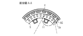
図2には図1によるジェネレータGの区分A−Aに沿った第1の詳細図ないし拡大図が示されている。 FIG. 2 shows a first detailed or enlarged view along section AA of the generator G according to FIG.
ここではステーター2の積層板5がクローズアップされ、この積層板5において複数のスロット5aが描写されている。
Here, the
ステーター2とローター1の間には、エアーギャップAGが存在しており、それに対してローター1は、それに固定されている複数のマグネット4と共に示されている。
An air gap AG exists between the
液体冷却のための中空パイプ11は、ジェネレータGの積層板5との熱的コンタクトのもとで接続されている。
The
図3には図1及び図2に関するジェネレータGの第2の詳細図ないし拡大図が示されている。 FIG. 3 shows a second detailed or enlarged view of the generator G with respect to FIGS.
積層板5のスロット5aは、ステーターコイル(詳細には示されていない)の金属巻線14を支持するのに用いられている。それに対して積層板5の第1の側は、エアーギャップAGに面しており、積層板5の第2の側は冷却目的のために積層板5と熱的に接続されている。
The
前記第2の側は、第1の側に対向する側に配置されており、さらに溶接箇所13を介して中空パイプ11と接続している。そのためこの溶接箇所13は熱的接続のために用いられている。
The second side is disposed on the side facing the first side, and is further connected to the
この中空パイプ11の内部は、冷却媒体が熱交換器8に若しくは熱交換器8から循環するように構成されている。
The inside of the
前記中空パイプ11は溶接箇所13を介してステーター2の積層板5との直接的な熱的コンタクトを形成している。
The
前述の溶接接続を用いた冷却システムは、中空パイプ11と積層板5の第2の側との間で行われ、それに対して中空パイプ11は有利な実施例によれば積層板5の第2の側に配置されている。
The cooling system using the weld connection described above takes place between the
別の有利な実施例によれば、中空パイプ11を積層板5によって包含することも可能である。それによれば中空パイプ11は積層板5の統合部分の一部として形成される。
According to another advantageous embodiment, the
さらに別の実施例によれば、中空パイプ11を金属巻線14若しくはスロット5aと共に集積することも可能であるし、前述した実施例を組合わせることも可能である。
According to yet another embodiment, the
さらに別の実施例によれば、ジェネレータGの"内部空気"のみを内側で循環させるようにしてもよい。それによりジェネレータGを全体として包み込むことが可能となる。液体冷却だけはジェネレータGからの熱の放出に用いられる。 According to a further embodiment, only the “internal air” of the generator G may be circulated inside. As a result, the generator G can be wrapped as a whole. Only liquid cooling is used to release heat from the generator G.
G 電気機械
AG エアーギャップ
1 ローター
2 ステーター
5 積層板
5a スロット
7 空気冷却装置
8 空気−液体熱交換器
9 冷却液体インレット
10 冷却液体アウトレット
11,12 液体冷却装置
14 金属巻線
G Electric machine AG Air gap 1
Claims (8)
前記電気機械(G)は、アウターローター(1)を含み、前記アウターローター(1)は複数のマグネット(4)を備えており、
前記電気機械(G)は、インナーステーター(2)を含み、前記インナーステーター(2)はベアリング(3)を介して前記アウターローター(1)と接続されており、
前記インナーローター(2)は複数の積層板(5)を含み、前記複数の積層板(5)は2つの端部プレート(15)によって前記インナーローター(2)に接続されており、
前記複数の積層板(5)は、複数のスロット(5a)を含み、前記複数のスロット(5a)は、ステーターコイルの金属巻線の支持に用いられており、
前記ステーターコイルは、前記複数の積層板(5)の前記複数のスロット(5a)から突出して当該ステーターコイルの巻線ヘッド(6)を形成しており、
前記複数のマグネット(4)は、前記アウターローター(1)と前記複数の積層板(5)の間にあるエアーギャップ(AG)内に部分的に配置されており、
さらに前記電気機械(G)はファン(7)を含んでおり、前記ファン(7)は、冷却空気が、前記電気機械(G)内部で、当該ファン(7)から前記端部プレート(15)の開口部を通り、前記巻線ヘッド(6)を通って、前記エアーギャップ(AG)を通り、前記端部プレート(15)に沿って、前記端部プレート(15)の開口部を通り、空気−液体熱交換器(8)を介して、再び前記ファン(7)に戻るように、冷却空気を循環させており、これによって、前記アウターローター(1)と、前記巻線ヘッド(6)と、前記複数の積層板(5)とが冷却され、
前記ファン(7)は、前記空気−液体熱交換器(8)と、循環する冷却空気からの熱が当該空気−液体熱交換器(8)に伝達するように接続されており、
前記空気−液体熱交換器(8)は、冷却液体インレット(9)と冷却液体アウトレット(10)に接続されており、前記冷却液体インレット(9)と冷却液体アウトレット(10)は、前記空気−液体熱交換器(8)への冷却液体の搬送と、前記空気−液体熱交換器(8)からの冷却液体の排出のために用いられており、それによって、熱が前記空気−液体熱交換器(8)から前記電気機械(G)の外部へ放出され、
複数の中空パイプ(11)が前記複数の積層板(5)との熱接触のために含まれており、
前記中空パイプ(11)の第1の端部は、前記冷却液体インレット(9)に接続され、前記中空パイプ(11)の第2の端部は、前記冷却液体アウトレット(10)に接続されて、冷却液体のための冷却循環路が形成されており、
前記空気−液体熱交換器(8)及び前記ファン(7)は、前記インナーステーター(2)と、前記2つの端部プレート(15)と、前記複数の積層板(5)とによって規定される所定のスペース内に配置されていることを特徴とする装置。 In an apparatus for cooling an electric machine (G),
The electric machine (G) includes an outer rotor (1) , and the outer rotor (1) includes a plurality of magnets (4) ,
The electric machine (G) includes an inner stator (2), and the inner stator (2) is connected to the outer rotor (1) via a bearing (3) ,
The inner rotor (2) includes a plurality of laminated plates (5), and the plurality of laminated plates (5) are connected to the inner rotor (2) by two end plates (15) ,
The plurality of laminated plates (5) include a plurality of slots (5a), and the plurality of slots (5a) are used for supporting metal windings of the stator coil ,
The stator coil protrudes from the plurality of slots (5a) of the plurality of laminated plates (5) to form a winding head (6) of the stator coil ,
The plurality of magnets (4) are partially disposed in an air gap (AG) between the outer rotor (1) and the plurality of laminated plates (5) ,
Further, the electric machine (G) includes a fan (7), and the fan (7) has cooling air from the fan (7) to the end plate (15) inside the electric machine (G). Through the winding head (6), through the air gap (AG), along the end plate (15), through the opening in the end plate (15), Cooling air is circulated through the air-liquid heat exchanger (8) so as to return to the fan (7) again, whereby the outer rotor (1) and the winding head (6) are circulated. And the plurality of laminated plates (5) are cooled ,
The fan (7) is connected to the air-liquid heat exchanger (8) so that heat from the circulating cooling air is transferred to the air-liquid heat exchanger (8) .
The air-liquid heat exchanger (8) is connected to a cooling liquid inlet (9) and a cooling liquid outlet (10), and the cooling liquid inlet (9) and the cooling liquid outlet (10) are connected to the air- Used for the transfer of cooling liquid to the liquid heat exchanger (8) and the discharge of cooling liquid from the air-liquid heat exchanger (8), whereby heat is transferred to the air-liquid heat exchange Discharged from the container (8) to the outside of the electric machine (G) ,
A plurality of hollow pipes (11) are included for thermal contact with the plurality of laminates (5) ,
A first end of the hollow pipe (11) is connected to the cooling liquid inlet (9), and a second end of the hollow pipe (11) is connected to the cooling liquid outlet (10). A cooling circuit for the cooling liquid is formed ,
The air-liquid heat exchanger (8) and the fan (7) are defined by the inner stator (2), the two end plates (15), and the plurality of laminated plates (5). An apparatus characterized by being arranged in a predetermined space .
前記中空パイプ(11)は、前記積層板(5)のスロット(5a)の統合されたパーツの一部である、請求項1記載の装置。 Before SL hollow pipe (11), said it is part of an integrated part of the metal-windings of stator coils (2) (14), and / or,
Said hollow pipe (11), the it is part of an integrated part of the slot (5a) of the laminate (5), apparatus according to claim 1.
Applications Claiming Priority (2)
| Application Number | Priority Date | Filing Date | Title |
|---|---|---|---|
| EP08018800A EP2182619B1 (en) | 2008-10-28 | 2008-10-28 | Arrangement for cooling of an electrical machine |
| EP08018800.6 | 2008-10-28 |
Publications (4)
| Publication Number | Publication Date |
|---|---|
| JP2010110206A JP2010110206A (en) | 2010-05-13 |
| JP2010110206A6 JP2010110206A6 (en) | 2010-07-29 |
| JP2010110206A5 JP2010110206A5 (en) | 2012-11-01 |
| JP5558780B2 true JP5558780B2 (en) | 2014-07-23 |
Family
ID=40551265
Family Applications (1)
| Application Number | Title | Priority Date | Filing Date |
|---|---|---|---|
| JP2009247352A Expired - Fee Related JP5558780B2 (en) | 2008-10-28 | 2009-10-28 | Equipment for electromechanical cooling |
Country Status (8)
| Country | Link |
|---|---|
| US (1) | US8242644B2 (en) |
| EP (1) | EP2182619B1 (en) |
| JP (1) | JP5558780B2 (en) |
| CN (1) | CN101728899B (en) |
| CA (1) | CA2683456C (en) |
| DK (1) | DK2182619T3 (en) |
| ES (1) | ES2393566T3 (en) |
| NZ (1) | NZ580109A (en) |
Families Citing this family (32)
| Publication number | Priority date | Publication date | Assignee | Title |
|---|---|---|---|---|
| CN102299585A (en) * | 2010-06-28 | 2011-12-28 | 昆山巩诚电器有限公司 | motor liquid cooling structure |
| DK2442060T3 (en) * | 2010-10-13 | 2014-01-06 | Siemens Ag | Generator, especially for a wind turbine |
| DK2458712T3 (en) * | 2010-11-26 | 2016-05-17 | Siemens Ag | Magnetic to a generator |
| DK2477311T3 (en) * | 2011-01-18 | 2014-03-24 | Siemens Ag | Generator, especially for a wind turbine |
| CN103765730B (en) * | 2011-03-09 | 2018-07-03 | Hdd伺服马达股份公司 | Cooled magnetic motor |
| DE102011006680A1 (en) * | 2011-04-01 | 2012-10-04 | Aloys Wobben | Core assembly |
| DE102011018539B4 (en) | 2011-04-18 | 2022-10-13 | Hans-Jürgen Esch | Design principle for electrical machines with an external rotor |
| US10886819B2 (en) | 2011-09-19 | 2021-01-05 | J. Rhett Mayor | Electric machine with direct winding heat exchanger |
| US9331553B2 (en) * | 2011-09-19 | 2016-05-03 | Georgia Tech Research Corporation | Systems and methods for direct winding cooling of electric machines |
| US9559569B2 (en) | 2012-02-13 | 2017-01-31 | Ge Aviation Systems Llc | Arrangement for cooling an electric machine with a layer of thermally conducting and electrically insulating material |
| KR101400333B1 (en) | 2012-08-07 | 2014-06-27 | 삼성중공업 주식회사 | Heat dissipating device of semiconductor device for wind power generator and temperature controlling method thereof |
| US9819248B2 (en) | 2012-12-31 | 2017-11-14 | Teco-Westinghouse Motor Company | Assemblies and methods for cooling electric machines |
| CN103199652B (en) * | 2013-03-13 | 2014-12-31 | 北京交通大学 | Gas-liquid interlaced cooling high power density motor |
| US9373988B2 (en) | 2013-03-15 | 2016-06-21 | Teco-Westinghouse Motor Company | Assemblies and methods for cooling electric machines |
| WO2015057181A1 (en) * | 2013-10-17 | 2015-04-23 | Otis Elevator Company | Cooling of machine for elevator system |
| EP2958215B1 (en) * | 2014-06-18 | 2018-02-21 | Siemens Aktiengesellschaft | Generator armature |
| EP3054569A1 (en) * | 2015-02-05 | 2016-08-10 | Siemens Aktiengesellschaft | Cooling arrangement |
| JP6332068B2 (en) * | 2015-02-09 | 2018-05-30 | 日本精工株式会社 | Motor, actuator, semiconductor manufacturing apparatus, and flat display manufacturing apparatus |
| EP3144528B1 (en) | 2015-09-15 | 2018-03-14 | Siemens Aktiengesellschaft | Wind turbine with a brake dust collector |
| JP6638427B2 (en) * | 2016-01-29 | 2020-01-29 | 富士電機株式会社 | Outer rotor type rotary electric machine |
| ES2813550T3 (en) * | 2016-07-21 | 2021-03-24 | Flender Gmbh | Cooling arrangement of a wind turbine generator |
| US11073136B2 (en) | 2017-02-02 | 2021-07-27 | Siemens Gamesa Renewable Energy A/S | Cooling arrangement |
| EP3382199B1 (en) * | 2017-03-27 | 2023-12-20 | Siemens Gamesa Renewable Energy A/S | Nacelle for a wind turbine including a cooling circuit |
| WO2018201442A1 (en) * | 2017-05-05 | 2018-11-08 | 罗伯特·博世有限公司 | Outer rotor-type electric motor |
| NL2021566B9 (en) * | 2018-09-05 | 2020-07-21 | Demaco Holland Bv | Assembly for a cryogenic motor and method for operating such motor |
| CN109412339B (en) | 2018-09-06 | 2020-04-28 | 新疆金风科技股份有限公司 | Motor and wind generating set |
| EP3908748A1 (en) | 2019-01-10 | 2021-11-17 | Vestas Wind Systems A/S | Improvements relating to cooling of electrical generators in wind turbines |
| DE102019109721A1 (en) * | 2019-04-12 | 2020-10-15 | Dr. Ing. H.C. F. Porsche Aktiengesellschaft | Rotor for an electric machine |
| CN111864991B (en) * | 2019-04-30 | 2024-02-23 | 金风科技股份有限公司 | Cooling system, motor and wind generating set |
| CN110649768B (en) * | 2019-09-18 | 2022-06-10 | 余果 | Alternating current generator |
| CN111740545B (en) * | 2020-08-26 | 2020-11-27 | 江苏嘉轩智能工业科技股份有限公司 | Air-water cooling hybrid cooling's permanent magnetism cylinder |
| EP4102683A1 (en) * | 2021-06-08 | 2022-12-14 | Siemens Gamesa Renewable Energy A/S | Cooling of an electric generator |
Family Cites Families (13)
| Publication number | Priority date | Publication date | Assignee | Title |
|---|---|---|---|---|
| US2970232A (en) * | 1958-10-21 | 1961-01-31 | Gen Electric | Conductor-cooled generator |
| US3727085A (en) * | 1971-09-30 | 1973-04-10 | Gen Dynamics Corp | Electric motor with facility for liquid cooling |
| DE2635829B2 (en) * | 1976-08-09 | 1978-08-03 | Kraftwerk Union Ag, 4330 Muelheim | Method for the determination of cooling water leaks in at least in the stator water-cooled windings of electrical machines as well as device for carrying out the method |
| US4728840A (en) * | 1987-03-16 | 1988-03-01 | Westinghouse Electric Corp. | Water-cooled AC and DC motor-generator set on a common shaft with series cooling flow path |
| DE3828902A1 (en) * | 1988-08-25 | 1990-03-08 | Max Planck Gesellschaft | HEAT SHIELD |
| GB9112059D0 (en) * | 1991-06-05 | 1991-07-24 | Jestar Ltd | Electrical machines |
| US6159300A (en) * | 1996-12-17 | 2000-12-12 | Canon Kabushiki Kaisha | Apparatus for forming non-single-crystal semiconductor thin film, method for forming non-single-crystal semiconductor thin film, and method for producing photovoltaic device |
| NL1013129C2 (en) * | 1999-09-24 | 2001-03-27 | Lagerwey Windturbine B V | Windmill. |
| US7160086B2 (en) * | 2003-01-29 | 2007-01-09 | Sundyne Corporation | Rotary machine cooling system |
| WO2005008860A2 (en) * | 2003-07-10 | 2005-01-27 | Magnetic Applications Inc. | Compact high power alternator |
| JP4049172B2 (en) * | 2005-07-13 | 2008-02-20 | 住友電気工業株式会社 | Wafer holder for wafer prober and wafer prober equipped with the same |
| US7443066B2 (en) * | 2005-07-29 | 2008-10-28 | General Electric Company | Methods and apparatus for cooling wind turbine generators |
| JP4982119B2 (en) * | 2006-06-29 | 2012-07-25 | 株式会社東芝 | Rotating electric machine |
-
2008
- 2008-10-28 EP EP08018800A patent/EP2182619B1/en not_active Not-in-force
- 2008-10-28 ES ES08018800T patent/ES2393566T3/en active Active
- 2008-10-28 DK DK08018800.6T patent/DK2182619T3/en active
-
2009
- 2009-10-01 NZ NZ580109A patent/NZ580109A/en not_active IP Right Cessation
- 2009-10-26 CA CA2683456A patent/CA2683456C/en not_active Expired - Fee Related
- 2009-10-27 US US12/606,328 patent/US8242644B2/en not_active Expired - Fee Related
- 2009-10-28 CN CN2009102081322A patent/CN101728899B/en not_active Expired - Fee Related
- 2009-10-28 JP JP2009247352A patent/JP5558780B2/en not_active Expired - Fee Related
Also Published As
| Publication number | Publication date |
|---|---|
| EP2182619A1 (en) | 2010-05-05 |
| JP2010110206A (en) | 2010-05-13 |
| CN101728899B (en) | 2013-09-04 |
| CA2683456C (en) | 2016-12-13 |
| CN101728899A (en) | 2010-06-09 |
| US20100102652A1 (en) | 2010-04-29 |
| ES2393566T3 (en) | 2012-12-26 |
| US8242644B2 (en) | 2012-08-14 |
| EP2182619B1 (en) | 2012-10-03 |
| CA2683456A1 (en) | 2010-04-28 |
| NZ580109A (en) | 2010-09-30 |
| DK2182619T3 (en) | 2012-11-19 |
Similar Documents
| Publication | Publication Date | Title |
|---|---|---|
| JP5558780B2 (en) | Equipment for electromechanical cooling | |
| JP2010110206A6 (en) | Equipment for electromechanical cooling | |
| JP5441607B2 (en) | Equipment for cooling electrical machines | |
| JP5692985B2 (en) | Equipment for electromechanical cooling | |
| US20100176670A1 (en) | Machine cooling scheme | |
| US20100102650A1 (en) | Arrangement for cooling of an electrical machine | |
| JP2010110206A5 (en) | ||
| JP2010107192A (en) | Cooling apparatus for electrical machine | |
| JP2010107192A6 (en) | Electric machine cooling system | |
| US20220213874A1 (en) | Cooling device, motor, and wind turbine set | |
| JP2010110203A (en) | Arrangement used to cool electrical machine | |
| JP2013519345A (en) | Vertical shaft type external rotor heat dissipation structure for electrical equipment | |
| US20220239195A1 (en) | Cooling system, electric motor and wind-power electric generator set | |
| US20220200396A1 (en) | Cooling system, electric motor and wind-power electric generator set | |
| US20050156470A1 (en) | Electric motor comprising a stator cooling unit | |
| CN113724963A (en) | Transformer, cooling system and wind generating set | |
| JP2006065940A (en) | Electric cooling apparatus and image forming apparatus |
Legal Events
| Date | Code | Title | Description |
|---|---|---|---|
| RD04 | Notification of resignation of power of attorney |
Free format text: JAPANESE INTERMEDIATE CODE: A7424 Effective date: 20101227 |
|
| RD04 | Notification of resignation of power of attorney |
Free format text: JAPANESE INTERMEDIATE CODE: A7424 Effective date: 20101228 |
|
| A521 | Request for written amendment filed |
Free format text: JAPANESE INTERMEDIATE CODE: A523 Effective date: 20120918 |
|
| A621 | Written request for application examination |
Free format text: JAPANESE INTERMEDIATE CODE: A621 Effective date: 20120918 |
|
| A131 | Notification of reasons for refusal |
Free format text: JAPANESE INTERMEDIATE CODE: A131 Effective date: 20131216 |
|
| A521 | Request for written amendment filed |
Free format text: JAPANESE INTERMEDIATE CODE: A523 Effective date: 20140311 |
|
| TRDD | Decision of grant or rejection written | ||
| A01 | Written decision to grant a patent or to grant a registration (utility model) |
Free format text: JAPANESE INTERMEDIATE CODE: A01 Effective date: 20140507 |
|
| A61 | First payment of annual fees (during grant procedure) |
Free format text: JAPANESE INTERMEDIATE CODE: A61 Effective date: 20140605 |
|
| R150 | Certificate of patent or registration of utility model |
Ref document number: 5558780 Country of ref document: JP Free format text: JAPANESE INTERMEDIATE CODE: R150 |
|
| LAPS | Cancellation because of no payment of annual fees |