JP5553196B2 - Vehicle reflector - Google Patents
Vehicle reflector Download PDFInfo
- Publication number
- JP5553196B2 JP5553196B2 JP2009193432A JP2009193432A JP5553196B2 JP 5553196 B2 JP5553196 B2 JP 5553196B2 JP 2009193432 A JP2009193432 A JP 2009193432A JP 2009193432 A JP2009193432 A JP 2009193432A JP 5553196 B2 JP5553196 B2 JP 5553196B2
- Authority
- JP
- Japan
- Prior art keywords
- angle
- degrees
- inclination angle
- rotation angle
- reference axis
- Prior art date
- Legal status (The legal status is an assumption and is not a legal conclusion. Google has not performed a legal analysis and makes no representation as to the accuracy of the status listed.)
- Active
Links
Images
Classifications
-
- F—MECHANICAL ENGINEERING; LIGHTING; HEATING; WEAPONS; BLASTING
- F21—LIGHTING
- F21V—FUNCTIONAL FEATURES OR DETAILS OF LIGHTING DEVICES OR SYSTEMS THEREOF; STRUCTURAL COMBINATIONS OF LIGHTING DEVICES WITH OTHER ARTICLES, NOT OTHERWISE PROVIDED FOR
- F21V7/00—Reflectors for light sources
- F21V7/04—Optical design
-
- G—PHYSICS
- G02—OPTICS
- G02B—OPTICAL ELEMENTS, SYSTEMS OR APPARATUS
- G02B5/00—Optical elements other than lenses
- G02B5/12—Reflex reflectors
- G02B5/122—Reflex reflectors cube corner, trihedral or triple reflector type
- G02B5/124—Reflex reflectors cube corner, trihedral or triple reflector type plural reflecting elements forming part of a unitary plate or sheet
-
- F—MECHANICAL ENGINEERING; LIGHTING; HEATING; WEAPONS; BLASTING
- F21—LIGHTING
- F21W—INDEXING SCHEME ASSOCIATED WITH SUBCLASSES F21K, F21L, F21S and F21V, RELATING TO USES OR APPLICATIONS OF LIGHTING DEVICES OR SYSTEMS
- F21W2107/00—Use or application of lighting devices on or in particular types of vehicles
Description
本発明は、車両用反射器に係り、特に観測角方向の光度が求められる測定ポイントにおける光度を従来よりも向上させることが可能な車両用反射器に関する。 The present invention relates to a vehicle reflector, and more particularly to a vehicle reflector capable of improving the light intensity at a measurement point where the light intensity in the observation angle direction is required.
従来、車両用反射器の分野においては、観測角方向の光度を高めることが求められており、この要求に応えるものとして、例えば、特許文献1に記載のものが提案されている。
Conventionally, in the field of vehicle reflectors, it has been required to increase the luminous intensity in the observation angle direction, and for example, the one described in
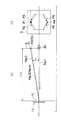
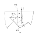
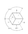
特許文献1に記載の車両用反射器は、図14、図15に示すように、水平に配置された基準軸AXに対して平行に入射する入射光線を基準軸AXに対して所定角度傾斜した方向に再帰反射する再帰反射素子211を複数含んでいる。再帰反射素子211は、略立方体の角部を形成するように隣接配置された第1反射面1、第2反射面2及び第3反射面3を備えており(図15参照)、各反射面1〜3はそれぞれ水平方向に配置された基準軸AXに対して同一角度(約35°17′)傾斜し(図14参照)、かつ、第2反射面2、第3反射面3はそれぞれ基準軸AXを中心に同一角度(±120°6′)回転した位置に形成されている(図15参照)。
As shown in FIGS. 14 and 15, the vehicle reflector described in
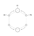
上記構成の車両用反射器210においては、水平方向に配置された基準軸AXに対して平行に入射する入射光線は、再帰反射素子(第1〜第3反射面1〜3)の作用により、基準軸AXに対して所定角度斜め上向きに反射し、図16に示すように、両側の集光ポイントP2、P3が最上部の集光ポイントP1に近づくため、観測角方向の光度が求められる測定ポイントの光度を向上させることが可能となる。
In the
本出願の発明者は、観測角方向の光度が求められる測定ポイントの光度を従来よりもさらに向上させるべく鋭意検討した結果、第1傾斜角度(ANG1)、第2傾斜角度(ANG2)、第3傾斜角度(ANG3)、下方向回転角度(ROT1)、上方向回転角度(ROT2)の合計5つのパラメータが、下式の関係を満たす場合に、リフレックスリフレクタの規格により求められる測定ポイントにおける光度が最大となり、上記特許文献1に記載のものよりも高い光度を得ることが可能となることを見出した。
The inventor of the present application intensively studied to further improve the light intensity at the measurement point where the light intensity in the observation angle direction is required, and as a result, the first inclination angle (ANG1), the second inclination angle (ANG2), the third When the total five parameters of the tilt angle (ANG3), the downward rotation angle (ROT1), and the upward rotation angle (ROT2) satisfy the relationship of the following equation, the luminous intensity at the measurement point required by the standard of the reflex reflector is It has been found that it is possible to obtain a maximum luminous intensity higher than that described in
ANG2>ANG3・・・(式1)
ANG2>ANG1・・・(式2)
ROT1>ROT2>120度・・・(式3)
但し、第1傾斜角度(ANG1)は第1反射面の基準軸に対する傾斜角度、第2傾斜角度(ANG2)は第2反射面の基準軸に対する傾斜角度、第3傾斜角度(ANG3)は第3反射面の基準軸に対する傾斜角度、下方向回転角度(ROT1)は基準軸を中心とした第2傾斜面の、基準面(第1反射面)からの回転角度、上方向回転角度(ROT2)は基準軸を中心とした第3傾斜面の、基準面(第1反射面)からの回転角度である。
ANG2> ANG3 (Formula 1)
ANG2> ANG1 (Formula 2)
ROT1>ROT2> 120 degrees (Equation 3)
However, the first tilt angle (ANG1) is the tilt angle with respect to the reference axis of the first reflecting surface, the second tilt angle (ANG2) is the tilt angle with respect to the reference axis of the second reflecting surface, and the third tilt angle (ANG3) is the third angle. The inclination angle of the reflecting surface with respect to the reference axis and the downward rotation angle (ROT1) are the rotation angle of the second inclined surface around the reference axis from the reference surface (first reflection surface), and the upward rotation angle (ROT2) is This is the rotation angle of the third inclined surface around the reference axis from the reference surface (first reflection surface).
本発明は、上記知見に基づいてなされたものであり、観測角方向の光度が求められる測定ポイントの光度をさらに向上させることが可能な車両用反射器及び当該車両用反射器を形成することが可能なリフレックスピンを提供することを目的とする。 The present invention has been made based on the above knowledge, and can form a vehicle reflector and a vehicle reflector capable of further improving the light intensity at a measurement point where the light intensity in the observation angle direction is required. The aim is to provide a possible reflex pin.
上記課題を解決するため、請求項1に記載の発明は、水平方向に配置された基準軸に対して平行に入射する入射光線を前記基準軸に対して所定角度斜め上向きに再帰反射して所定の観測角方向に集光させるように構成された再帰反射素子を複数含む車両用反射器において、前記再帰反射素子は、略立方体の角部を形成するように隣接配置された第1反射面、第2反射面及び第3反射面を含んでおり、前記第1反射面は、前記基準軸に対して第1傾斜角度傾斜しており、前記第2反射面は、前記基準軸に対して第2傾斜角度傾斜し、かつ、前記第1反射面から前記基準軸を中心に第1回転角度回転した位置に形成されており、前記第3反射面は、前記基準軸に対して第3傾斜角度傾斜し、かつ、前記第1反射面から前記基準軸を中心に前記第2反射面とは反対方向に第2回転角度回転した位置に形成されており、前記第1傾斜角度、第2傾斜角度、第3傾斜角度、第1回転角度及び第2回転角度が下式の関係を満たすことを特徴とする車両用反射器。ANG2>ANG3、ANG2>ANG1、ROT1>ROT2>120度。但し、ANG1:第1傾斜角度、ANG2:第2傾斜角度、ANG3:第3傾斜角度、ROT1:第1回転角度、ROT2:第2回転角度。 To solve the above problems, a first aspect of the present invention, and retroreflected at a predetermined angle obliquely upward incident light that is incident parallel to the reference placed on the horizontal axis with respect to the reference axis predetermined In the vehicle reflector including a plurality of retroreflective elements configured to condense in the observation angle direction, the retroreflective element is a first reflective surface disposed adjacent to form a substantially cubic corner, A second reflective surface and a third reflective surface, wherein the first reflective surface is inclined at a first inclination angle with respect to the reference axis, and the second reflective surface is The third reflection surface is formed at a position inclined by two inclination angles and rotated by a first rotation angle about the reference axis from the first reflection surface, and the third reflection surface has a third inclination angle with respect to the reference axis. The second tilted and centered on the reference axis from the first reflecting surface. The first tilt angle, the second tilt angle, the third tilt angle, the first rotation angle, and the second rotation angle are represented by the following formulas. The vehicle reflector characterized by satisfy | filling. ANG2> ANG3, ANG2> ANG1, ROT1>ROT2> 120 degrees. However, ANG1: 1st inclination angle, ANG2: 2nd inclination angle, ANG3: 3rd inclination angle, ROT1: 1st rotation angle, ROT2: 2nd rotation angle.
請求項1に記載の発明によれば、従来技術とは異なり、ANG2>ANG3、 ANG2>ANG1、ROT1>ROT2>120度の角度条件を満たすように、第1傾斜角度、第2傾斜角度、第3傾斜角度、第1回転角度、第2回転角度の5つのパラメータそれぞれが設定されるため(従来技術は実質的に2つのパラメータが設定されるのみである)、観測角方向の光度が求められる測定ポイントの光度を従来よりもさらに向上させることが可能となる。 According to the first aspect of the present invention, unlike the prior art, the first tilt angle, the second tilt angle, the first tilt angle, and so on so as to satisfy the angle conditions of ANG2> ANG3, ANG2> ANG1, ROT1> ROT2> 120 degrees. Since each of the five parameters of the three tilt angles, the first rotation angle, and the second rotation angle is set (the prior art only sets two parameters in practice), the luminous intensity in the observation angle direction is required. It becomes possible to further improve the luminous intensity of the measurement point as compared with the conventional case.
請求項2に記載の発明は、請求項1に記載の発明において、前記所定の観測角は、0.33度であることを特徴とする。
The invention according to
請求項2に記載の発明によれば、ANG2>ANG3、ANG2>ANG1、ROT1>ROT2>120度の角度条件を満たすことで、観測角(0.33度)方向の光度が求められる測定ポイントの光度を、従来よりも向上させることが可能となる。 According to the second aspect of the present invention, the measurement point for which the luminous intensity in the observation angle (0.33 degree) direction is obtained by satisfying the angular conditions of ANG2> ANG3, ANG2> ANG1, ROT1> ROT2> 120 degrees. The luminous intensity can be improved as compared with the conventional case.
請求項3に記載の発明は、請求項2に記載の発明において、前記第1傾斜角度は、35.273度±0.0027度、前記第2傾斜角度は、35.310度±0.0027度、前記第3傾斜角度は、35.305度±0.0027度、前記第1回転角度は、120.07度±0.0027度、前記第2回転角度は、120.06度±0.0027度であることを特徴とする。
The invention according to
請求項3に記載の発明によれば、第1傾斜角度=35.273度±0.0027度、第2傾斜角度=35.310度±0.0027度、第3傾斜角度=35.305度±0.0027度、第1回転角度=120.07度±0.0027度、第2回転角度=120.06度±0.0027度の範囲に設定しても、光線追跡のずれが20%以内に収まるため、実際の散乱現象や形状変化に対して大きくずれることがない車両用反射器を構成することが可能となる。 According to the third aspect of the invention, the first inclination angle = 35.273 degrees ± 0.0027 degrees, the second inclination angle = 35.310 degrees ± 0.0027 degrees, and the third inclination angle = 35.305 degrees. Even if it is set within the range of ± 0.0027 degrees, the first rotation angle = 120.07 degrees ± 0.0027 degrees, and the second rotation angle = 120.06 degrees ± 0.0027 degrees, the ray tracing deviation is 20%. Therefore, it is possible to configure a vehicle reflector that does not deviate greatly with respect to an actual scattering phenomenon or shape change.
請求項4に記載の発明は、水平方向に配置された基準軸に対して平行に入射する入射光線を前記基準軸に対して所定角度斜め上向きに再帰反射して所定の観測角方向に集光させるように構成された再帰反射素子を成形するために用いられる先端部を含むリフレックスピンにおいて、前記先端部は、略立方体の角部を形成するように隣接配置された第1傾斜面、第2傾斜面及び第3傾斜面を含んでおり、前記第1傾斜面は、リフレックスピンの中心軸に対して第1傾斜角度傾斜しており、前記第2傾斜面は、前記リフレックスピンの中心軸に対して第2傾斜角度傾斜し、かつ、前記第1傾斜面から前記リフレックスピンの中心軸を中心に第1回転角度回転した位置に形成されており、前記第3傾斜面は、前記リフレックスピンの中心軸に対して第3傾斜角度傾斜し、かつ、前記第1傾斜面から前記リフレックスピンの中心軸を中心に前記第2傾斜面とは反対方向に第2回転角度回転した位置に形成されており、前記第1傾斜角度、第2傾斜角度、第3傾斜角度、第1回転角度及び第2回転角度が下式の関係を満たすことを特徴とするリフレックスピン。ANG2>ANG3、ANG2>ANG1、ROT1>ROT2>120度。但し、ANG1:第1傾斜角度、ANG2:第2傾斜角度、ANG3:第3傾斜角度、ROT1:第1回転角度、ROT2:第2回転角度。 According to a fourth aspect of the present invention, incident light incident in parallel to a reference axis arranged in the horizontal direction is retroreflected obliquely upward by a predetermined angle with respect to the reference axis and condensed in a predetermined observation angle direction. In a reflex pin including a tip portion used for forming a retroreflective element configured to be configured , the tip portion includes a first inclined surface and a first inclined surface arranged adjacent to each other so as to form a substantially cubic corner portion. The first inclined surface is inclined at a first inclination angle with respect to the central axis of the reflex pin, and the second inclined surface is formed on the reflex pin. The second inclined angle is inclined with respect to a central axis, and is formed at a position rotated from the first inclined surface by a first rotation angle around the central axis of the reflex pin. With respect to the central axis of the reflex pin The first inclined surface is formed at a position rotated from the first inclined surface by a second rotation angle in a direction opposite to the second inclined surface about the central axis of the reflex pin, A reflex pin characterized in that an inclination angle, a second inclination angle, a third inclination angle, a first rotation angle, and a second rotation angle satisfy the following relationship. ANG2> ANG3, ANG2> ANG1, ROT1>ROT2> 120 degrees. However, ANG1: 1st inclination angle, ANG2: 2nd inclination angle, ANG3: 3rd inclination angle, ROT1: 1st rotation angle, ROT2: 2nd rotation angle.
請求項4に記載の発明によれば、従来技術とは異なり、ANG2>ANG3、ANG2>ANG1、ROT1>ROT2>120度の角度条件を満たすように、第1傾斜角度、第2傾斜角度、第3傾斜角度、第1回転角度、第2回転角度の5つのパラメータそれぞれが設定されるため(従来技術は実質的に2つのパラメータが設定されるのみである)、観測角方向の光度が求められる測定ポイントの光度を従来よりもさらに向上させることが可能な再帰反射素子を成形することが可能となる。 According to the fourth aspect of the invention, unlike the prior art, the first inclination angle, the second inclination angle, the first inclination angle, the ANG2> ANG3, the ANG2> ANG1, the ROT1> ROT2> 120 degrees so as to satisfy the angle condition. Since each of the five parameters of the three tilt angles, the first rotation angle, and the second rotation angle is set (the prior art only sets two parameters in practice), the luminous intensity in the observation angle direction is required. It is possible to mold a retroreflective element that can further improve the luminous intensity of the measurement point as compared with the conventional case.
請求項5に記載の発明は、水平方向に配置された基準軸に対して平行に入射する入射光線を前記基準軸に対して所定角度斜め上向きに再帰反射して所定の観測角方向に集光させるように構成された再帰反射素子を複数含む車両用反射器において、前記再帰反射素子は、略立方体の角部を形成するように隣接配置された第1反射面、第2反射面及び第3反射面を含んでおり、前記第1反射面は、前記基準軸に対して第1傾斜角度傾斜しており、前記第2反射面は、前記基準軸に対して第2傾斜角度傾斜し、かつ、前記第1反射面から前記基準軸を中心に第1回転角度回転した位置に形成されており、前記第3反射面は、前記基準軸に対して第3傾斜角度傾斜し、かつ、前記第1反射面から前記基準軸を中心に前記第2反射面とは反対方向に第2回転角度回転した位置に形成されており、前記第1傾斜角度、第2傾斜角度、第3傾斜角度、第1回転角度及び第2回転角度はそれぞれ、リフレックスリフレクタの規格により求められる測定点における光度が最大となるように個別に調整されていることを特徴とする。 According to a fifth aspect of the present invention, incident light incident in parallel to a reference axis arranged in the horizontal direction is retroreflected obliquely upward by a predetermined angle with respect to the reference axis and condensed in a predetermined observation angle direction. In the vehicle reflector including a plurality of retroreflective elements configured to be configured, the retroreflective element includes a first reflective surface, a second reflective surface, and a third reflective surface that are arranged adjacent to each other so as to form a substantially cubic corner. Including a reflective surface, wherein the first reflective surface is inclined at a first inclination angle with respect to the reference axis, the second reflective surface is inclined at a second inclination angle with respect to the reference axis, and The third reflection surface is formed at a position rotated by a first rotation angle about the reference axis from the first reflection surface, and the third reflection surface is inclined at a third inclination angle with respect to the reference axis, and Second from the first reflecting surface in the direction opposite to the second reflecting surface with the reference axis as the center The first inclination angle, the second inclination angle, the third inclination angle, the first rotation angle, and the second rotation angle are respectively measured at measurement points determined by the standard of the reflex reflector. It is characterized by being individually adjusted so that the luminous intensity is maximized.
請求項5に記載の発明によれば、従来技術とは異なり、リフレックスリフレクタの規格により求められる測定点における光度が最大となるように、第1傾斜角度、第2傾斜角度、第3傾斜角度、第1回転角度、第2回転角度の5つのパラメータそれぞれが設定されるため(従来技術は実質的に2つのパラメータが設定されるのみである)、観測角方向の光度が求められる測定ポイントの光度を従来よりもさらに向上させることが可能となる。 According to the fifth aspect of the invention, unlike the prior art, the first inclination angle, the second inclination angle, and the third inclination angle are set so that the luminous intensity at the measurement point required by the standard of the reflex reflector is maximized. Since each of the five parameters of the first rotation angle and the second rotation angle is set (in the conventional technology, only two parameters are substantially set), the measurement point at which the luminous intensity in the observation angle direction is obtained It becomes possible to further improve the luminous intensity than before.
本発明によれば、観測角方向の光度が求められる測定ポイントの光度をさらに向上させることが可能な車両用反射器及び当該車両用反射器を形成することが可能なリフレックスピンを提供することが可能となる。 According to the present invention, it is possible to provide a vehicle reflector capable of further improving the light intensity at a measurement point where the light intensity in the observation angle direction is required, and a reflex pin capable of forming the vehicle reflector. Is possible.
以下、本発明の一実施形態である車両用反射器について図面を参照しながら説明する。 Hereinafter, a vehicle reflector according to an embodiment of the present invention will be described with reference to the drawings.
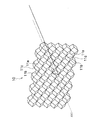
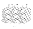
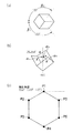
本実施形態の車両用反射器10は、自動車や二輪車等の車両に装着されるいわゆるリフレックスリフレクタであり、一般的なリフレックスリフレクタと同様、アクリルやポリカーボネイト等の透明材料により形成されており、図1に示すように、周囲車両等からの照射光が入射する表面、その反対側の裏面、当該裏面に図2に示すような複数のリフレックスピン20(先端部21)により成形された複数の再帰反射素子11等を備えている。
The
[再帰反射素子]
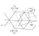
再帰反射素子11は、図1、図3に示すように、左右方向面11a(本発明の第1反射面に相当)、鉛直方向下側に配置される下方向面11b(本発明の第2反射面に相当)及び鉛直方向上側に配置される上方向面11c(本発明の第3反射面に相当)を含んでおり、これら各面11a〜11cは、略立方体の角部(コーナーキューブ部ともいう)を形成するように隣接配置されている。
[Retroreflective element]
As shown in FIGS. 1 and 3, the
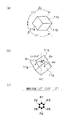
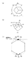
図3、図13(a)に示すように、光源30から照射され、水平方向に配置された基準軸AX1(リフレックスピン20の中心軸AX2に相当)に対して平行な光線Ray1は、再帰反射素子11に入射すると、各面11a〜11cで再帰反射(例えば図3に示すように合計3回反射)し、入射した各面11a〜11cの各領域11a1〜11c2に対応する方向(基準軸AX1に対して斜め上方に向かう3方向と基準軸AX1に対して斜め下方に向かう3方向)に反射される。そして、当該反射光のうち、基準軸AX1に対して斜め上方に向かう3方向の反射光Ray2〜Ray4については、最上部のポイントP1、その下方両側のポイントP2、P3にそれぞれ集光し(図13(b)参照)、基準軸AX1に対して斜め下方に向かう3方向の反射光については、最下部のポイントP4、その上方両側のポイントP5、P6にそれぞれ集光する(図13(b)参照)。
As shown in FIGS. 3 and 13A, the ray Ray1 irradiated from the
本出願の発明者は、第1傾斜角度α1、第2傾斜角度α2、第3傾斜角度α3、下方向回転角度β1(本発明の第1回転角度に相当)、上方向回転角度β2(本発明の第2回転角度に相当)の合計5つのパラメータそれぞれを個別に調整し、基準軸AX1に対して斜め上方に向かう3方向の反射光が集光するポイントP1〜P3(図4(c)、図5(c)、図6(c)参照)を観察したところ、次の事実を見出した。但し、第1傾斜角度α1は左右方向面11aの基準軸AX1に対する角度、第2傾斜角度α2は下方向面11bの基準軸AX1に対する角度、第3傾斜角度α3は上方向面11cの基準軸AX1に対する角度、下方向回転角度β1は基準軸AX1を中心とした下方向面11bの、基準面(左右方向面11a)からの角度、上方向回転角度β2は基準軸A1を中心とした上方向面11cの、基準面(左右方向面11a)からの角度である。
The inventor of the present application has a first tilt angle α1, a second tilt angle α2, a third tilt angle α3, a downward rotation angle β1 (corresponding to the first rotation angle of the present invention), an upward rotation angle β2 (the present invention). Points P1 to P3 (refer to FIG. 4 (c), FIG. 4 (c), and FIG. 4C). Observation of FIG. 5 (c) and FIG. 6 (c)) revealed the following facts. However, the first inclination angle α1 is an angle with respect to the reference axis AX1 of the left-
第1に、第1傾斜角度α1、第2傾斜角度α2、第3傾斜角度α3を大きくすると、両側のポイントP2、P3が最上部のポイントP1側に近づくこと。すなわち、第1傾斜角度α1、第2傾斜角度α2、第3傾斜角度α3を調整することで、ポイントP2、P3の上下位置を調整することが可能なこと(図4(c)、図5(c)参照)。 First, when the first inclination angle α1, the second inclination angle α2, and the third inclination angle α3 are increased, the points P2 and P3 on both sides approach the uppermost point P1 side. That is, by adjusting the first inclination angle α1, the second inclination angle α2, and the third inclination angle α3, the vertical positions of the points P2 and P3 can be adjusted (FIG. 4C, FIG. 5). c)).
第2に、下方向回転角度β1、上方向回転角度β2を調整することで、基準軸AX1に対して斜め上方に向かう3方向の反射光R2〜R4が集光するポイントP1〜P3が観測角度付近に近づくこと(図6(c)参照)。これとともに、基準軸AX1に対して斜め下方に向かう3方向の反射光が集光するポイントP4〜P6がポイントP1〜P3よりも広い範囲に分布すること(図6(c)参照)。 Second, by adjusting the downward rotation angle β1 and the upward rotation angle β2, the points P1 to P3 where the reflected lights R2 to R4 in three directions obliquely upward with respect to the reference axis AX1 are collected are observation angles. Approaching the vicinity (see FIG. 6C). At the same time, the points P4 to P6 where the reflected light in the three directions obliquely downward with respect to the reference axis AX1 are distributed over a wider range than the points P1 to P3 (see FIG. 6C).
本出願の発明者は、上記知見に基づいて、第1傾斜角度α1、第2傾斜角度α2、第3傾斜角度α3、下方向回転角度β1、上方向回転角度β2の合計5つのパラメータそれぞれを個別に調整し、リフレックスリフレクタの規格(SAE J594f)により求められる測定ポイント(光源30から30.5m離れた位置に配置された垂直スクリーンS上のCenter : 10DEG UP 0DEG 10DEG, Left20 : 5DEG UP 0DEG 5DEG DOWN, Right : 5DEG UP 0DEG 5DEG DOWN)における光度が最大となる(すなわち最適化される)角度条件を検討した。 Based on the above knowledge, the inventor of the present application individually sets a total of five parameters, the first tilt angle α1, the second tilt angle α2, the third tilt angle α3, the downward rotation angle β1, and the upward rotation angle β2. The measurement point (Center on the vertical screen S placed at a position 30.5 m away from the light source 30: Center: 10DEG UP 0DEG 10DEG, Left20: 5DEG UP 0DEG 5DEG DOWN, Right: 5DEG UP 0DEG 5DEG DOWN) The angle condition that maximizes the light intensity (ie, is optimized) was examined.
その結果、下式の関係を満たす場合に、リフレックスリフレクタの規格(SAE J594f)により求められる測定ポイントにおける光度が最大となる(すなわち最適化される)ことを見出した。 As a result, it has been found that the luminous intensity at the measurement point determined by the standard of the reflex reflector (SAE J594f) is maximized (that is, optimized) when the following relationship is satisfied.
ANG2>ANG3・・・(式1)
ANG2>ANG1・・・(式2)
ROT1>ROT2>120度・・・(式3)
但し、ANG1は第1傾斜角度α1、ANG2は第2傾斜角度α2、ANG3は第3傾斜角度α3、ROT1は第1回転角度β1、ROT2は第2回転角度β2を表している。
ANG2> ANG3 (Formula 1)
ANG2> ANG1 (Formula 2)
ROT1>ROT2> 120 degrees (Equation 3)
However, ANG1 represents the first tilt angle α1, ANG2 represents the second tilt angle α2, ANG3 represents the third tilt angle α3, ROT1 represents the first rotation angle β1, and ROT2 represents the second rotation angle β2.
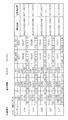
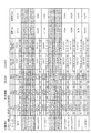
図7は、観測角度0.17度、0.20度、0.23度、0.33度、0.36度ごとに、リフレックスリフレクタの規格(SAE J594f)により求められる測定ポイントにおける光度が最大となるように(すなわち最適化されるように)、第1傾斜角度α1、第2傾斜角度α2、第3傾斜角度α3、下方向回転角度β1、上方向回転角度β2の合計5つのパラメータそれぞれを個別に調整した例である。 FIG. 7 shows the luminous intensity at the measurement point determined by the standard of the reflex reflector (SAE J594f) for each observation angle of 0.17 degrees, 0.20 degrees, 0.23 degrees, 0.33 degrees, and 0.36 degrees. In order to maximize (that is, to be optimized), a total of five parameters, a first inclination angle α1, a second inclination angle α2, a third inclination angle α3, a downward rotation angle β1, and an upward rotation angle β2, respectively. This is an example of adjusting individually.
図7を参照すると、観測角度0.17度、0.20度、0.23度、0.33度、0.36度全てにおいて、すなわち、0.17≦観測角度R≦0.36の範囲において、上記(式1)〜(式3)の角度条件を満たすことが分かる。 Referring to FIG. 7, the observation angles are 0.17 degrees, 0.20 degrees, 0.23 degrees, 0.33 degrees, and 0.36 degrees, that is, a range of 0.17 ≦ observation angle R ≦ 0.36. It can be seen that the angle conditions of (Expression 1) to (Expression 3) are satisfied.
また、図7、図13(b)を参照すると、観測角度が0.33度の場合には、第1傾斜角度α1=35.273度、第2傾斜角度α2=35.310度、第3傾斜角度α3=35.305度、第1回転角度β1=120.07度、第2回転角度β2=120.06度のときに、従来技術(図16参照)と比べ、両側のポイントP2、P3が最上部のポイントP1側により一層近づくこととなり(図13(b)参照)、測定ポイントにおける光度が最大となる(すなわち最適化される)ことが分かる。 7 and 13B, when the observation angle is 0.33 degrees, the first inclination angle α1 = 35.273 degrees, the second inclination angle α2 = 35.310 degrees, the third When the inclination angle α3 is 35.305 degrees, the first rotation angle β1 is 120.07 degrees, and the second rotation angle β2 is 120.06 degrees, the points P2 and P3 on both sides are compared with the conventional technique (see FIG. 16). Is closer to the uppermost point P1 side (see FIG. 13B), and it can be seen that the light intensity at the measurement point is maximized (that is, optimized).
同様に、観測角度が0.20度の場合には、第1傾斜角度α1=35.285度、第2傾斜角度α2=35.304度、第3傾斜角度α3=35.264度、第1回転角度β1=120.06度、第2回転角度β2=120.01度のときに、各測定ポイントにおける光度が最大となる(すなわち最適化される)ことが分かる。 Similarly, when the observation angle is 0.20 degrees, the first inclination angle α1 = 35.285 degrees, the second inclination angle α2 = 35.304 degrees, the third inclination angle α3 = 35.264 degrees, the first It can be seen that the luminous intensity at each measurement point is maximized (that is, optimized) when the rotation angle β1 is 120.06 degrees and the second rotation angle β2 is 120.01 degrees.
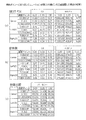
図8(a)は、観測角度が0.20度、0.33度、第1傾斜角度α1、第2傾斜角度α2、第3傾斜角度α3、下方向回転角度β1、上方向回転角度β2それぞれが図7に示した角度の場合の、測定ポイントにおける光度を表した表である。 FIG. 8A shows an observation angle of 0.20 degrees, 0.33 degrees, a first tilt angle α1, a second tilt angle α2, a third tilt angle α3, a downward rotation angle β1, and an upward rotation angle β2. 8 is a table showing the luminous intensity at the measurement point in the case of the angle shown in FIG.
図8(b)は、比較例(従来例)であり、従来と同様、第1傾斜角度α1、第2傾斜角度α2、第3傾斜角度α3、下方向回転角度β1、上方向回転角度β2それぞれが35°17′、35°17′、35°17′、120°6′、120°6′の場合の、測定ポイントにおける光度を表した表である。 FIG. 8B is a comparative example (conventional example), and similarly to the conventional example, the first inclination angle α1, the second inclination angle α2, the third inclination angle α3, the downward rotation angle β1, and the upward rotation angle β2. Is a table showing the light intensity at the measurement point when 35 ° 17 ′, 35 ° 17 ′, 35 ° 17 ′, 120 ° 6 ′, and 120 ° 6 ′.
図8(c)は、図8(b)に示した例と比較しての図8(a)に示した例の効率を表した表である。図8(c)を参照すると、観測角度が0.33度、0.20度のいずれの場合においても、比較例の効率を上回っていることが分かる。すなわち、観測角度が0.33度、0.20度の場合には、上記(式1)〜(式3)の角度条件を満たすことで、比較例を上回る効率のよい車両用反射器10を構成することが可能となることが分かる。
FIG. 8C is a table showing the efficiency of the example shown in FIG. 8A compared with the example shown in FIG. Referring to FIG. 8 (c), it can be seen that the efficiency of the comparative example is exceeded in both cases where the observation angle is 0.33 degrees and 0.20 degrees. That is, when the observation angles are 0.33 degrees and 0.20 degrees, the
図9は、観測角度が0.33度の場合の角度条件(第1傾斜角度α1=35.273度、第2傾斜角度α2=35.310度、第3傾斜角度α3=35.305度、第1回転角度β1=120.07度、第2回転角度β2=120.06度)を、±0.0002又は±0.0027変化させた場合の誤差及び角度差を表した表である。図9を参照すると、観測角度が0.33度の場合には、第1傾斜角度=35.282度±0.0027度、第2傾斜角度=35.310度±0.0027度、第3傾斜角度=35.305度±0.0027度、第1回転角度=120.07度±0.0027度、第2回転角度=120.06度±0.0027度の範囲内であれば、光線追跡のずれが20%以内に収まるため、実際の散乱現象や形状変化に対して大きくずれないことが分かる。 FIG. 9 shows the angle conditions when the observation angle is 0.33 degrees (first inclination angle α1 = 35.273 degrees, second inclination angle α2 = 35.310 degrees, third inclination angle α3 = 35.305 degrees, It is a table | surface showing the error and angle difference at the time of changing ± 0.0002 or ± 0.0027 of 1st rotation angle (beta) 1 = 120.07 degree | times and 2nd rotation angle (beta) 2 = 120.06 degree | times. Referring to FIG. 9, when the observation angle is 0.33 degrees, the first inclination angle = 35.282 degrees ± 0.0027 degrees, the second inclination angle = 35.310 degrees ± 0.0027 degrees, If the tilt angle = 35.305 ° ± 0.0027 °, the first rotation angle = 120.07 ° ± 0.0027 °, and the second rotation angle = 120.06 ° ± 0.0027 °, the light beam Since the tracking shift is within 20%, it can be seen that there is no significant shift with respect to the actual scattering phenomenon or shape change.
以上説明したように、本実施形態の車両用反射器10(再帰反射要素11)によれば、従来技術とは異なり、ANG2>ANG3、ANG2>ANG1、ROT1>ROT2>120度の角度条件を満たすように、第1傾斜角度α1、第2傾斜角度α2、第3傾斜角度α3、第1回転角度β1、第2回転角度β2の5つのパラメータそれぞれが設定されるため(従来技術は実質的に2つのパラメータが設定されるのみである)、従来技術(図16)と比べ、両側のポイントP2、P3が最上部のポイントP1側により一層近づくこととなる(図13(b)参照)。 As described above, according to the vehicle reflector 10 (retroreflective element 11) of the present embodiment, unlike the prior art, the angle condition of ANG2> ANG3, ANG2> ANG1, ROT1> ROT2> 120 degrees is satisfied. Thus, each of the five parameters of the first inclination angle α1, the second inclination angle α2, the third inclination angle α3, the first rotation angle β1, and the second rotation angle β2 is set (substantially 2 in the conventional technique). Only one parameter is set), compared to the prior art (FIG. 16), the points P2 and P3 on both sides are closer to the uppermost point P1 side (see FIG. 13B).
これにより、リフレックスリフレクタの規格(SAE J594f)により光度が求められる測定ポイント(光源30から30.5m離れた位置に配置された垂直スクリーンS上のCenter : 10DEG UP 0DEG 10DEG, Left20 : 5DEG UP 0DEG 5DEG DOWN, Right : 5DEG UP 0DEG 5DEG DOWN)の光度を、従来技術よりもさらに向上させることが可能となる(図8(c)参照)。
As a result, measurement points (Center: 10DEG UP 0DEG 10DEG, Left20: 5DEG UP 0DEG on the vertical screen S arranged at a position 30.5 m away from the
[リフレックスピン]
次に、上記再帰反射要素11の成形に用いられるリフレックスピン20について説明する。
[Reflex pin]
Next, the
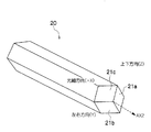
リフレックスピン20は、図10に示すように、その先端部21に形成された左右方向面21a(本発明の第1傾斜面に相当)、下方向面21b(本発明の第2傾斜面に相当)及び上方向面21c(本発明の第3傾斜面に相当)を含んでおり、これら各面21a〜21cは、略立方体の角部(コーナーキューブ部ともいう)を形成するように隣接配置されている。
As shown in FIG. 10, the
左右方向面21aはリフレックスピン20の長手方向に延びる中心軸AX2に対して第1傾斜角度α1傾斜しており、下方向面21bは中心軸AX2に対して第2傾斜角度α2傾斜し、かつ、基準面(左右方向面21a)から中心軸AX2を中心に第1回転角度β1回転した位置に形成されており、上方向面21bは中心軸AX2に対して第3傾斜角度α3傾斜し、かつ、基準面(左右方向面21a)から中心軸AX2を中心に下方向面21bとは反対方向に第2回転角度β2回転した位置に形成されている。なお、各面21a〜21cはそれぞれ、上記(式1)〜(式3)で示した角度関係を満たすように設定されている。
The left-
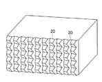
図10は、各面21a〜21cそれぞれを略正方形に形成し、中心軸AX2に垂直な断面形状が六角形のリフレックスピン20を構成した例である。このリフレックスピン20は、例えば、図2に示すように組み合わされ、複数の再帰反射素子11が図1に示すように配置された車両用反射器の成形に用いられる。
FIG. 10 shows an example in which each of the
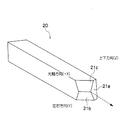
図11は、図10に示した断面形状が六角形のリフレックスピン20の両側を切断し、断面形状が四角形のリフレックスピン20を構成した例である。このリフレックスピン20は、例えば、図12に示すように組み合わされ、複数の再帰反射素子11と同様の再帰反射素子11が図1と同様に配置された車両用反射器の成形に用いられる。
FIG. 11 shows an example in which the
図11のリフレックスピンにおいても第1傾斜角度、第2傾斜角度、第3傾斜角度、第1回転角度、第2回転角度を備えるものであるため、図10のリフレックスピンと同様に集光ポイントを集中させることによる測定ポイント光度の向上が可能である。 Since the reflex pin of FIG. 11 also includes the first tilt angle, the second tilt angle, the third tilt angle, the first rotation angle, and the second rotation angle, the condensing point is similar to the reflex pin of FIG. It is possible to improve the measurement point luminous intensity by concentrating the light.
以上説明したように、本実施形態のリフレックスピン20によれば、従来技術とは異なり、ANG2>ANG3、ANG2>ANG1、ROT1>ROT2>120度の角度条件を満たすように、第1傾斜角度α1、第2傾斜角度α2、第3傾斜角度α3、第1回転角度β1、第2回転角度β2の5つのパラメータそれぞれが設定されるため(従来技術は実質的に2つのパラメータが設定されるのみである)、従来技術(図16)と比べ、両側のポイントP2、P3が最上部のポイントP1側により一層近づくこととなる(図13(b)参照)。
As described above, according to the
これにより、リフレックスリフレクタの規格(SAE J594f)により光度が求められる測定ポイント(光源30から30.5m離れた位置に配置された垂直スクリーンS上のCenter : 10DEG UP 0DEG 10DEG, Left20 : 5DEG UP 0DEG 5DEG DOWN, Right : 5DEG UP 0DEG 5DEG DOWN)の光度を、従来技術よりもさらに向上させることが可能な(図8(c)参照)再帰反射素子11(を含む車両用反射器10)を成形することが可能となる。
As a result, measurement points (Center: 10DEG UP 0DEG 10DEG, Left20: 5DEG UP 0DEG on the vertical screen S arranged at a position 30.5 m away from the
上記実施形態はあらゆる点で単なる例示にすぎない。これらの記載によって本発明は限定的に解釈されるものではない。本発明はその精神または主要な特徴から逸脱することなく他の様々な形で実施することができる。 The above embodiment is merely an example in all respects. The present invention is not construed as being limited to these descriptions. The present invention can be implemented in various other forms without departing from the spirit or main features thereof.
10…車両用反射器、11…再帰反射素子、11a…左右方向面、11b…下方向面、11c…上方向面、20…リフレックスピン、21a…左右方向面、21b…下方向面、21c…上方向面
DESCRIPTION OF
Claims (5)
前記再帰反射素子は、略立方体の角部を形成するように隣接配置された第1反射面、第2反射面及び第3反射面を含んでおり、
前記第1反射面は、前記基準軸に対して第1傾斜角度傾斜しており、
前記第2反射面は、前記基準軸に対して第2傾斜角度傾斜し、かつ、前記第1反射面から前記基準軸を中心に第1回転角度回転した位置に形成されており、
前記第3反射面は、前記基準軸に対して第3傾斜角度傾斜し、かつ、前記第1反射面から前記基準軸を中心に前記第2反射面とは反対方向に第2回転角度回転した位置に形成されており、
前記第1傾斜角度、第2傾斜角度、第3傾斜角度、第1回転角度及び第2回転角度が下式の関係を満たすことを特徴とする車両用反射器。
ANG2>ANG3
ANG2>ANG1
ROT1>ROT2>120度
但し、ANG1:第1傾斜角度、ANG2:第2傾斜角度、ANG3:第3傾斜角度、ROT1:第1回転角度、ROT2:第2回転角度 A retroreflective element configured to retroreflect incident light incident in parallel to a reference axis disposed in a horizontal direction obliquely upward at a predetermined angle with respect to the reference axis and collect the incident light in a predetermined observation angle direction. In a vehicle reflector including a plurality of
The retroreflective element includes a first reflection surface, a second reflection surface, and a third reflection surface that are arranged adjacent to each other so as to form a substantially cubic corner.
The first reflecting surface is inclined at a first inclination angle with respect to the reference axis;
The second reflection surface is formed at a position inclined at a second inclination angle with respect to the reference axis and rotated from the first reflection surface by a first rotation angle around the reference axis,
The third reflective surface is inclined at a third inclination angle with respect to the reference axis, and rotated by a second rotation angle from the first reflective surface about the reference axis in a direction opposite to the second reflective surface. Formed in position,
The vehicle reflector according to claim 1, wherein the first tilt angle, the second tilt angle, the third tilt angle, the first rotation angle, and the second rotation angle satisfy the following relationship.
ANG2> ANG3
ANG2> ANG1
ROT1>ROT2> 120 degrees However, ANG1: first inclination angle, ANG2: second inclination angle, ANG3: third inclination angle, ROT1: first rotation angle, ROT2: second rotation angle
前記第2傾斜角度は、35.310度±0.0027度、
前記第3傾斜角度は、35.305度±0.0027度、
前記第1回転角度は、120.07度±0.0027度、
前記第2回転角度は、120.06度±0.0027度であることを特徴とする請求項2に記載の車両用反射器。 The first inclination angle is 35.273 ° ± 0.0027 °,
The second inclination angle is 35.310 degrees ± 0.0027 degrees,
The third inclination angle is 35.305 degrees ± 0.0027 degrees,
The first rotation angle is 120.07 degrees ± 0.0027 degrees,
The vehicle reflector according to claim 2, wherein the second rotation angle is 120.06 degrees ± 0.0027 degrees.
前記先端部は、略立方体の角部を形成するように隣接配置された第1傾斜面、第2傾斜面及び第3傾斜面を含んでおり、
前記第1傾斜面は、リフレックスピンの中心軸に対して第1傾斜角度傾斜しており、
前記第2傾斜面は、前記リフレックスピンの中心軸に対して第2傾斜角度傾斜し、かつ、前記第1傾斜面から前記リフレックスピンの中心軸を中心に第1回転角度回転した位置に形成されており、
前記第3傾斜面は、前記リフレックスピンの中心軸に対して第3傾斜角度傾斜し、かつ、前記第1傾斜面から前記リフレックスピンの中心軸を中心に前記第2傾斜面とは反対方向に第2回転角度回転した位置に形成されており、
前記第1傾斜角度、第2傾斜角度、第3傾斜角度、第1回転角度及び第2回転角度が下式の関係を満たすことを特徴とするリフレックスピン。
ANG2>ANG3
ANG2>ANG1
ROT1>ROT2>120度
但し、ANG1:第1傾斜角度、ANG2:第2傾斜角度、ANG3:第3傾斜角度、ROT1:第1回転角度、ROT2:第2回転角度 A retroreflective element configured to retroreflect incident light incident in parallel to a reference axis disposed in a horizontal direction obliquely upward at a predetermined angle with respect to the reference axis and collect the incident light in a predetermined observation angle direction. In a reflex pin including a tip part used for molding,
The tip portion includes a first inclined surface, a second inclined surface, and a third inclined surface that are adjacently arranged so as to form a corner portion of a substantially cube.
The first inclined surface is inclined at a first inclination angle with respect to a central axis of the reflex pin,
The second inclined surface is inclined at a second inclination angle with respect to the central axis of the reflex pin, and is rotated from the first inclined surface by a first rotation angle about the central axis of the reflex pin. Formed,
The third inclined surface is inclined at a third inclination angle with respect to a central axis of the reflex pin, and is opposite to the second inclined surface from the first inclined surface around the central axis of the reflex pin. Formed at a position rotated by a second rotation angle in the direction,
The reflex pin characterized in that the first tilt angle, the second tilt angle, the third tilt angle, the first rotation angle, and the second rotation angle satisfy the following relationship.
ANG2> ANG3
ANG2> ANG1
ROT1>ROT2> 120 degrees However, ANG1: first inclination angle, ANG2: second inclination angle, ANG3: third inclination angle, ROT1: first rotation angle, ROT2: second rotation angle
前記再帰反射素子は、略立方体の角部を形成するように隣接配置された第1反射面、第2反射面及び第3反射面を含んでおり、
前記第1反射面は、前記基準軸に対して第1傾斜角度傾斜しており、
前記第2反射面は、前記基準軸に対して第2傾斜角度傾斜し、かつ、前記第1反射面から前記基準軸を中心に第1回転角度回転した位置に形成されており、
前記第3反射面は、前記基準軸に対して第3傾斜角度傾斜し、かつ、前記第1反射面から前記基準軸を中心に前記第2反射面とは反対方向に第2回転角度回転した位置に形成されており、
前記第1傾斜角度、第2傾斜角度、第3傾斜角度、第1回転角度及び第2回転角度はそれぞれ、リフレックスリフレクタの規格により求められる測定点における光度が最大となるように個別に調整されていることを特徴とする車両用反射器。 A retroreflective element configured to retroreflect incident light incident in parallel to a reference axis disposed in a horizontal direction obliquely upward at a predetermined angle with respect to the reference axis and collect the incident light in a predetermined observation angle direction. In a vehicle reflector including a plurality of
The retroreflective element includes a first reflection surface, a second reflection surface, and a third reflection surface that are arranged adjacent to each other so as to form a substantially cubic corner.
The first reflecting surface is inclined at a first inclination angle with respect to the reference axis;
The second reflection surface is formed at a position inclined at a second inclination angle with respect to the reference axis and rotated from the first reflection surface by a first rotation angle around the reference axis,
The third reflective surface is inclined at a third inclination angle with respect to the reference axis, and rotated by a second rotation angle from the first reflective surface about the reference axis in a direction opposite to the second reflective surface. Formed in position,
The first inclination angle, the second inclination angle, the third inclination angle, the first rotation angle, and the second rotation angle are individually adjusted so that the luminous intensity at the measurement point required by the standard of the reflex reflector is maximized. The vehicle reflector characterized by the above-mentioned.
Priority Applications (3)
| Application Number | Priority Date | Filing Date | Title |
|---|---|---|---|
| JP2009193432A JP5553196B2 (en) | 2009-08-24 | 2009-08-24 | Vehicle reflector |
| US12/858,039 US8414135B2 (en) | 2009-08-24 | 2010-08-17 | Reflector for vehicle |
| CA2713586A CA2713586C (en) | 2009-08-24 | 2010-08-19 | Reflector for vehicle |
Applications Claiming Priority (1)
| Application Number | Priority Date | Filing Date | Title |
|---|---|---|---|
| JP2009193432A JP5553196B2 (en) | 2009-08-24 | 2009-08-24 | Vehicle reflector |
Publications (2)
| Publication Number | Publication Date |
|---|---|
| JP2011043760A JP2011043760A (en) | 2011-03-03 |
| JP5553196B2 true JP5553196B2 (en) | 2014-07-16 |
Family
ID=43605263
Family Applications (1)
| Application Number | Title | Priority Date | Filing Date |
|---|---|---|---|
| JP2009193432A Active JP5553196B2 (en) | 2009-08-24 | 2009-08-24 | Vehicle reflector |
Country Status (3)
| Country | Link |
|---|---|
| US (1) | US8414135B2 (en) |
| JP (1) | JP5553196B2 (en) |
| CA (1) | CA2713586C (en) |
Families Citing this family (6)
| Publication number | Priority date | Publication date | Assignee | Title |
|---|---|---|---|---|
| JP5729584B2 (en) * | 2010-04-15 | 2015-06-03 | スタンレー電気株式会社 | Vehicle reflector and reflex pin |
| JP5716895B2 (en) * | 2010-12-27 | 2015-05-13 | スタンレー電気株式会社 | Vehicle reflector and reflex pin |
| USD810323S1 (en) * | 2014-02-04 | 2018-02-13 | Federico Gigli | Tile |
| US10925268B1 (en) * | 2015-03-13 | 2021-02-23 | Ray D. Flasco | Inside corner cubic surface reflector fishing lure |
| WO2022097458A1 (en) * | 2020-11-03 | 2022-05-12 | ナルックス株式会社 | Forming mold, plate members of forming mold, and method for manufacturing forming mold |
| USD975452S1 (en) * | 2021-03-18 | 2023-01-17 | Trias Holding Ag | Fabric |
Family Cites Families (8)
| Publication number | Priority date | Publication date | Assignee | Title |
|---|---|---|---|---|
| USRE29396E (en) * | 1975-02-18 | 1977-09-13 | Amerace Corporation | Pin having nonaligned cube axis and pin axis and bundle of such pins |
| US4703999A (en) * | 1986-06-16 | 1987-11-03 | Minnesota Mining And Manufacturing Company | Wide-angle-reflective cube-corner retroreflective sheeting |
| CA2169807C (en) | 1996-02-19 | 1999-09-07 | Italo Caroli | Reflex pin with adjusted angle |
| JP2001517809A (en) * | 1997-09-25 | 2001-10-09 | ミネソタ マイニング アンド マニュファクチャリング カンパニー | Dual use reflective article |
| US6172824B1 (en) * | 1997-10-21 | 2001-01-09 | Trustees Of Princeton University | Low loss prism retroreflectors for relative index of refraction less than the square root of 2 |
| US7156527B2 (en) * | 2003-03-06 | 2007-01-02 | 3M Innovative Properties Company | Lamina comprising cube corner elements and retroreflective sheeting |
| US7370981B2 (en) * | 2003-12-24 | 2008-05-13 | Avery Dennison Corporation | Cube corner retroreflector with limited range |
| EP1946290B1 (en) * | 2005-11-01 | 2011-06-29 | The Arizona Board of Regents on behalf of the University of Arizona | Polarization coupling cube-corner retro-reflectors |
-
2009
- 2009-08-24 JP JP2009193432A patent/JP5553196B2/en active Active
-
2010
- 2010-08-17 US US12/858,039 patent/US8414135B2/en active Active
- 2010-08-19 CA CA2713586A patent/CA2713586C/en active Active
Also Published As
| Publication number | Publication date |
|---|---|
| JP2011043760A (en) | 2011-03-03 |
| US20110044066A1 (en) | 2011-02-24 |
| CA2713586C (en) | 2017-12-19 |
| CA2713586A1 (en) | 2011-02-24 |
| US8414135B2 (en) | 2013-04-09 |
Similar Documents
| Publication | Publication Date | Title |
|---|---|---|
| JP5553196B2 (en) | Vehicle reflector | |
| JP6948818B2 (en) | Automatic vehicle headlight module for emitting light beams | |
| JP3834596B2 (en) | Asymmetric corner cube article and manufacturing method | |
| JP4777900B2 (en) | Composite triangular pyramid cube corner retroreflective sheet and retroreflective object | |
| JP5091864B2 (en) | Triangular pyramid cube corner retroreflective article and method for manufacturing the same | |
| RU2352967C2 (en) | Array of corner reflectors shaped by three-level grooves | |
| KR880006555A (en) | Cube retroreflective article with desired divergence profile | |
| WO2007064033A1 (en) | Retroreflection article | |
| KR20040105604A (en) | Optical device, area light apparatus and display | |
| JP2011511303A (en) | Retroreflector | |
| US9372288B2 (en) | Cube-corner retroreflective sheeting | |
| EA019545B1 (en) | Multi-directional cube corner retroreflective object | |
| JP5339032B2 (en) | Projector-type headlamp unit, headlamp and projection lens for headlamp | |
| JP4694374B2 (en) | Retroreflective sheet | |
| JP5729584B2 (en) | Vehicle reflector and reflex pin | |
| JP2009537023A (en) | Retroreflector | |
| KR102133964B1 (en) | Retroreflective sheet using cube corner of transformed structure | |
| JP5716895B2 (en) | Vehicle reflector and reflex pin | |
| WO2010067583A1 (en) | Retroreflective article | |
| JP2019203981A (en) | Reflector | |
| EP4224055A1 (en) | Vehicle lamp | |
| CA1113440A (en) | Retroreflector | |
| KR20130135415A (en) | Cube-corner type retroreflective sheet | |
| JP2009198878A (en) | Triangular pyramid-shaped cube corner retroreflection article | |
| CA1096832A (en) | Retroreflector |
Legal Events
| Date | Code | Title | Description |
|---|---|---|---|
| A621 | Written request for application examination |
Free format text: JAPANESE INTERMEDIATE CODE: A621 Effective date: 20120809 |
|
| A977 | Report on retrieval |
Free format text: JAPANESE INTERMEDIATE CODE: A971007 Effective date: 20130710 |
|
| A131 | Notification of reasons for refusal |
Free format text: JAPANESE INTERMEDIATE CODE: A131 Effective date: 20130719 |
|
| A521 | Request for written amendment filed |
Free format text: JAPANESE INTERMEDIATE CODE: A523 Effective date: 20130913 |
|
| TRDD | Decision of grant or rejection written | ||
| A01 | Written decision to grant a patent or to grant a registration (utility model) |
Free format text: JAPANESE INTERMEDIATE CODE: A01 Effective date: 20140502 |
|
| A61 | First payment of annual fees (during grant procedure) |
Free format text: JAPANESE INTERMEDIATE CODE: A61 Effective date: 20140515 |
|
| R150 | Certificate of patent or registration of utility model |
Ref document number: 5553196 Country of ref document: JP Free format text: JAPANESE INTERMEDIATE CODE: R150 |
|
| R250 | Receipt of annual fees |
Free format text: JAPANESE INTERMEDIATE CODE: R250 |
|
| R250 | Receipt of annual fees |
Free format text: JAPANESE INTERMEDIATE CODE: R250 |
|
| R250 | Receipt of annual fees |
Free format text: JAPANESE INTERMEDIATE CODE: R250 |
|
| R250 | Receipt of annual fees |
Free format text: JAPANESE INTERMEDIATE CODE: R250 |
|
| R250 | Receipt of annual fees |
Free format text: JAPANESE INTERMEDIATE CODE: R250 |
|
| R250 | Receipt of annual fees |
Free format text: JAPANESE INTERMEDIATE CODE: R250 |
|
| R250 | Receipt of annual fees |
Free format text: JAPANESE INTERMEDIATE CODE: R250 |