JP5551148B2 - Stapler device, medical instrument, and tissue capture device - Google Patents
Stapler device, medical instrument, and tissue capture device Download PDFInfo
- Publication number
- JP5551148B2 JP5551148B2 JP2011500938A JP2011500938A JP5551148B2 JP 5551148 B2 JP5551148 B2 JP 5551148B2 JP 2011500938 A JP2011500938 A JP 2011500938A JP 2011500938 A JP2011500938 A JP 2011500938A JP 5551148 B2 JP5551148 B2 JP 5551148B2
- Authority
- JP
- Japan
- Prior art keywords
- staple
- tissue
- housing
- anvil
- drive
- Prior art date
- Legal status (The legal status is an assumption and is not a legal conclusion. Google has not performed a legal analysis and makes no representation as to the accuracy of the status listed.)
- Active
Links
Images


Classifications
-
- A—HUMAN NECESSITIES
- A61—MEDICAL OR VETERINARY SCIENCE; HYGIENE
- A61B—DIAGNOSIS; SURGERY; IDENTIFICATION
- A61B17/00—Surgical instruments, devices or methods, e.g. tourniquets
- A61B17/068—Surgical staplers, e.g. containing multiple staples or clamps
- A61B17/072—Surgical staplers, e.g. containing multiple staples or clamps for applying a row of staples in a single action, e.g. the staples being applied simultaneously
-
- A—HUMAN NECESSITIES
- A61—MEDICAL OR VETERINARY SCIENCE; HYGIENE
- A61B—DIAGNOSIS; SURGERY; IDENTIFICATION
- A61B17/00—Surgical instruments, devices or methods, e.g. tourniquets
- A61B17/064—Surgical staples, i.e. penetrating the tissue
- A61B17/0644—Surgical staples, i.e. penetrating the tissue penetrating the tissue, deformable to closed position
-
- A—HUMAN NECESSITIES
- A61—MEDICAL OR VETERINARY SCIENCE; HYGIENE
- A61B—DIAGNOSIS; SURGERY; IDENTIFICATION
- A61B17/00—Surgical instruments, devices or methods, e.g. tourniquets
- A61B17/00234—Surgical instruments, devices or methods, e.g. tourniquets for minimally invasive surgery
-
- A—HUMAN NECESSITIES
- A61—MEDICAL OR VETERINARY SCIENCE; HYGIENE
- A61B—DIAGNOSIS; SURGERY; IDENTIFICATION
- A61B17/00—Surgical instruments, devices or methods, e.g. tourniquets
- A61B17/068—Surgical staplers, e.g. containing multiple staples or clamps
- A61B17/072—Surgical staplers, e.g. containing multiple staples or clamps for applying a row of staples in a single action, e.g. the staples being applied simultaneously
- A61B17/07207—Surgical staplers, e.g. containing multiple staples or clamps for applying a row of staples in a single action, e.g. the staples being applied simultaneously the staples being applied sequentially
-
- A—HUMAN NECESSITIES
- A61—MEDICAL OR VETERINARY SCIENCE; HYGIENE
- A61B—DIAGNOSIS; SURGERY; IDENTIFICATION
- A61B17/00—Surgical instruments, devices or methods, e.g. tourniquets
- A61B17/10—Surgical instruments, devices or methods, e.g. tourniquets for applying or removing wound clamps, e.g. containing only one clamp or staple; Wound clamp magazines
-
- A—HUMAN NECESSITIES
- A61—MEDICAL OR VETERINARY SCIENCE; HYGIENE
- A61B—DIAGNOSIS; SURGERY; IDENTIFICATION
- A61B17/00—Surgical instruments, devices or methods, e.g. tourniquets
- A61B17/11—Surgical instruments, devices or methods, e.g. tourniquets for performing anastomosis; Buttons for anastomosis
- A61B17/115—Staplers for performing anastomosis in a single operation
- A61B17/1155—Circular staplers comprising a plurality of staples
-
- A—HUMAN NECESSITIES
- A61—MEDICAL OR VETERINARY SCIENCE; HYGIENE
- A61F—FILTERS IMPLANTABLE INTO BLOOD VESSELS; PROSTHESES; DEVICES PROVIDING PATENCY TO, OR PREVENTING COLLAPSING OF, TUBULAR STRUCTURES OF THE BODY, e.g. STENTS; ORTHOPAEDIC, NURSING OR CONTRACEPTIVE DEVICES; FOMENTATION; TREATMENT OR PROTECTION OF EYES OR EARS; BANDAGES, DRESSINGS OR ABSORBENT PADS; FIRST-AID KITS
- A61F5/00—Orthopaedic methods or devices for non-surgical treatment of bones or joints; Nursing devices; Anti-rape devices
- A61F5/0003—Apparatus for the treatment of obesity; Anti-eating devices
- A61F5/0013—Implantable devices or invasive measures
- A61F5/0083—Reducing the size of the stomach, e.g. gastroplasty
-
- A—HUMAN NECESSITIES
- A61—MEDICAL OR VETERINARY SCIENCE; HYGIENE
- A61B—DIAGNOSIS; SURGERY; IDENTIFICATION
- A61B17/00—Surgical instruments, devices or methods, e.g. tourniquets
- A61B17/064—Surgical staples, i.e. penetrating the tissue
-
- A—HUMAN NECESSITIES
- A61—MEDICAL OR VETERINARY SCIENCE; HYGIENE
- A61B—DIAGNOSIS; SURGERY; IDENTIFICATION
- A61B17/00—Surgical instruments, devices or methods, e.g. tourniquets
- A61B17/32—Surgical cutting instruments
- A61B17/3205—Excision instruments
- A61B17/32053—Punch like cutting instruments, e.g. using a cylindrical or oval knife
-
- A—HUMAN NECESSITIES
- A61—MEDICAL OR VETERINARY SCIENCE; HYGIENE
- A61B—DIAGNOSIS; SURGERY; IDENTIFICATION
- A61B17/00—Surgical instruments, devices or methods, e.g. tourniquets
- A61B2017/00535—Surgical instruments, devices or methods, e.g. tourniquets pneumatically or hydraulically operated
- A61B2017/00539—Surgical instruments, devices or methods, e.g. tourniquets pneumatically or hydraulically operated hydraulically
-
- A—HUMAN NECESSITIES
- A61—MEDICAL OR VETERINARY SCIENCE; HYGIENE
- A61B—DIAGNOSIS; SURGERY; IDENTIFICATION
- A61B17/00—Surgical instruments, devices or methods, e.g. tourniquets
- A61B2017/00743—Type of operation; Specification of treatment sites
- A61B2017/00818—Treatment of the gastro-intestinal system
-
- A—HUMAN NECESSITIES
- A61—MEDICAL OR VETERINARY SCIENCE; HYGIENE
- A61B—DIAGNOSIS; SURGERY; IDENTIFICATION
- A61B17/00—Surgical instruments, devices or methods, e.g. tourniquets
- A61B17/068—Surgical staplers, e.g. containing multiple staples or clamps
- A61B17/072—Surgical staplers, e.g. containing multiple staples or clamps for applying a row of staples in a single action, e.g. the staples being applied simultaneously
- A61B2017/07214—Stapler heads
- A61B2017/07271—Stapler heads characterised by its cartridge
-
- A—HUMAN NECESSITIES
- A61—MEDICAL OR VETERINARY SCIENCE; HYGIENE
- A61B—DIAGNOSIS; SURGERY; IDENTIFICATION
- A61B17/00—Surgical instruments, devices or methods, e.g. tourniquets
- A61B17/30—Surgical pincettes without pivotal connections
- A61B2017/306—Surgical pincettes without pivotal connections holding by means of suction
-
- A—HUMAN NECESSITIES
- A61—MEDICAL OR VETERINARY SCIENCE; HYGIENE
- A61F—FILTERS IMPLANTABLE INTO BLOOD VESSELS; PROSTHESES; DEVICES PROVIDING PATENCY TO, OR PREVENTING COLLAPSING OF, TUBULAR STRUCTURES OF THE BODY, e.g. STENTS; ORTHOPAEDIC, NURSING OR CONTRACEPTIVE DEVICES; FOMENTATION; TREATMENT OR PROTECTION OF EYES OR EARS; BANDAGES, DRESSINGS OR ABSORBENT PADS; FIRST-AID KITS
- A61F5/00—Orthopaedic methods or devices for non-surgical treatment of bones or joints; Nursing devices; Anti-rape devices
- A61F5/0003—Apparatus for the treatment of obesity; Anti-eating devices
- A61F5/0013—Implantable devices or invasive measures
Abstract
Description
本発明は、概して内視鏡手術を行うシステムおよび方法の分野に関し、具体的には、体腔内組織の内視鏡によるステープル固定のシステムと方法に関する。 The present invention relates generally to the field of systems and methods for performing endoscopic surgery and, more particularly, to systems and methods for endoscopic stapling of tissue in a body cavity.
人間の胃Sと付随器官の解剖学的図を図1Aに示す。食道Eは口から胃Sの近位部に食物を運ぶ。Zラインすなわち食道胃接合部Zは、食道の薄い組織と胃壁の厚い組織との間の不規則な形をした境界である。食道胃接合部位Gは、食道Eの遠位部、Zライン、および胃Sの近位部を包含する部位である。 An anatomical view of the human stomach S and associated organs is shown in FIG. 1A. The esophagus E carries food from the mouth to the proximal part of the stomach S. The Z-line or esophagogastric junction Z is an irregularly shaped boundary between the thin tissue of the esophagus and the thick tissue of the stomach wall. The esophagogastric junction site G is a site including the distal portion of the esophagus E, the Z line, and the proximal portion of the stomach S.
胃Sには、近位端の胃底部Fと遠位端の胃前庭部Aとが含まれる。胃前庭部Aは、小腸の近位部位である、十二指腸Dに接続する幽門Pに食物を送る。幽門P内に十二指腸から胃への食物の逆流を防ぐ括約筋がある。十二指腸の遠位に位置する、小腸の中間部位は、空腸Jである。 The stomach S includes a gastric fundus F at the proximal end and a gastric vestibule A at the distal end. The gastric vestibule part A sends food to the pylorus P connected to the duodenum D, which is the proximal site of the small intestine. Within the pylorus P is a sphincter that prevents the reflux of food from the duodenum to the stomach. The intermediate site of the small intestine, located distal to the duodenum, is jejunum J.
図1Bは、胃壁を形成する組織層を図示する。一番外側の層は、漿膜層すなわち「漿膜」Sであり、胃内部を覆う一番内側の層は粘膜層すなわち「粘膜」MUCである。粘膜下層SMおよび多層の筋層Mが、粘膜と漿膜の間にある。 FIG. 1B illustrates the tissue layers that form the stomach wall. The outermost layer is the serosa layer or “serosa” S, and the innermost layer that covers the stomach is the mucosa layer or “mucosa” MUC. There is a submucosa SM and multiple muscle layers M between the mucosa and the serosa.
体腔内の組織に対するステープルのようなファスナの内視鏡的適用のための多くの出願がある。それらの適用のいくつかは、体腔の組織のひだまたは折り畳みのような組織構造を形成することを含む。 There are many applications for the endoscopic application of fasteners such as staples to tissue in body cavities. Some of those applications include forming tissue structures such as folds or folds of body cavity tissue.
2004年10月8日の国際出願日を有するWO2005/037152の国際出願および2006年5月23日出願の出願番号第11/439,461号の米国特許出願(共に、参照して、本明細書に組み込む)を含め、いくつかの先行出願で、医療用埋め込みを胃の内部に形成された組織構造に連結することによる方法を説明している。それらの出願によると、体重減少を引き起こすための装置(たとえば、胃への食物の流れを制限しあるいは閉塞することによる、および/または、胃容積の一部をふさぐことによる)が、胃組織から形成される組織のトンネルまたはひだに結合される。 WO 2005/037152 international application having an international filing date of October 8, 2004 and US patent application No. 11 / 439,461, filed May 23, 2006 (both referenced herein) In some prior applications, including the above, the method by coupling a medical implant to a tissue structure formed within the stomach is described. According to those applications, a device for causing weight loss (eg, by restricting or blocking the flow of food to the stomach and / or by blocking a portion of the stomach volume) is removed from the stomach tissue. Combined with the tunnel or fold of tissue formed.
たとえば、米国特許出願第11/439,461号は、体重減少を引き起こす制限的および/または閉塞的埋め込みを説明する。一実施の形態では、胃の食道胃接合部位に形成された組織ひだに柔らかいループが接続される。流れの制限的および/または閉塞的埋め込みのような、埋め込みは、ループ2を通り、よって胃の中に保持される。 For example, US patent application Ser. No. 11 / 439,461 describes restrictive and / or occlusive implantation that causes weight loss. In one embodiment, a soft loop is connected to a tissue fold formed at the stomach esophagogastric junction. Implants, such as flow restrictive and / or occlusive implants, pass through loop 2 and are thus retained in the stomach.
別の例では、組織ひだ自身が、十分に必要な処理を提供する。たとえば、WO2005/037152または本書に参照して組み込む2006年10月3日出願の同時継続中の米国特許出願第11/542,457号、米国特許公開第2007−0219571号に開示されるように、ひだを用いて胃容積を減少し、または胃の中に流れの制限物を形成する。 In another example, the tissue pleat itself provides the necessary processing. For example, as disclosed in WO 2005/037152 or co-pending U.S. Patent Application No. 11 / 542,457, U.S. Patent Publication No. 2007-0219571, filed Oct. 3, 2006, which is incorporated herein by reference. The pleats are used to reduce gastric volume or to form a flow restriction in the stomach.
他のタイプの埋め込みを、種々の目的のそのようなひだや他の組織構造に接続してもよい。そのような埋め込みには、胃食道逆流症の処理用人工弁、胃刺激装置、pHモニタ、および、薬、生物製剤または細胞を胃や消化管(GI tract)中のどこかにリリースする薬剤抽出装置を含むが、それらには限定されない。そのような薬剤抽出装置は、レプチン(満腹感を生み出すホルモン)、グレリン(空腹感を生み出すホルモン)、オクトレオチド(グレリンレベルを下げ、よって空腹を減少させる)、インシュリン、化学療法剤、術後の外傷、潰瘍、裂傷などで助けとなる自然生物製剤(たとえば、成長因子、サイトカイン)を放出するものを含む。さらに別の埋め込みは、特定の細胞種類がくっつき、成長し、および、生物学的に活性な遺伝子生成物を消化管に提供するプラットフォームおよび/または治療目的の局所放射線源を提供する放射線源プラットフォームを提供し、診断用リガンド(diagnostic ligands)を固定して、特定の正常なまたは病気の状態の証拠のため消化管をサンプリングするのに用いられるプラットフォームを提供し、あるいは、カメラおよび他の画像収集装置を通じて消化管を撮像するための固定点を提供するための種類でもよい。 Other types of implants may be connected to such folds or other tissue structures for various purposes. Such implants include prosthetic valves for gastroesophageal reflux disease, gastric stimulators, pH monitors, and drug extractions that release drugs, biologics or cells somewhere in the stomach or GI tract. Including but not limited to devices. Such drug extraction devices include leptin (a hormone that produces a feeling of fullness), ghrelin (a hormone that produces a feeling of hunger), octreotide (which lowers ghrelin levels and thus reduces hunger), insulin, chemotherapeutic agents, postoperative trauma Including those that release natural biologics (eg, growth factors, cytokines) that help in ulcers, lacerations, and the like. Yet another implant is a platform that provides for a specific cell type to attach, grow, and provide a biologically active gene product to the digestive tract and / or a local radiation source for therapeutic purposes. Provides a platform used to fix and fix diagnostic ligands and sample the gastrointestinal tract for evidence of certain normal or disease states, or cameras and other image acquisition devices It may be of a kind for providing a fixed point for imaging the gastrointestinal tract through.
上記の先行出願は、漿膜組織(すなわち胃の外壁の組織)領域を互いに接触した状態に維持する方法で、組織のひだ、ポケットあるいはトンネルを形成することの利点に着目している。時間が経つと、向かい合った漿膜層間に形成された接着は、胃の運動や埋め込まれた装置により作用する力にも関わらず、長期間のひだ、ポケット、組織の維持を容易にする強力な結合を生ずる。 The above prior application focuses on the advantages of forming tissue folds, pockets, or tunnels in a manner that maintains serous tissue (ie, tissue of the stomach outer wall) in contact with each other. Over time, the bond formed between the opposing serosal layers is a strong bond that facilitates long-term folds, pockets, and tissue maintenance, despite gastric movements and forces exerted by implanted devices Is produced.
ひだが形成される用途に無関係に、より侵襲的手術または腹腔鏡法を用いるよりむしろ、食道を通過させた器具を用いて胃内部からなされる工程を用いてひだを形成することの方が遥かに好ましい。本出願は、口を通って胃に至り、胃壁に漿膜−漿膜ひだを形成するのに使用される内視鏡的ステープラについて述べる。 Regardless of the application in which the pleats are formed, it is much more likely to form the folds using a process done from the inside of the stomach using instruments that have passed through the esophagus rather than using more invasive surgery or laparoscopic techniques. Is preferable. This application describes an endoscopic stapler used to reach the stomach through the mouth and form serosal-serosa folds in the stomach wall.
一態様において、本発明は、組織に対してステープルを打ち込むステープラ装置(12)を含む。その装置は、(i)第1部材ハウジング若しくはステープルハウジング(28)と、ステープルハウジングに関して独立して移動可能なステープルホルダ(78)とを有する第1またはステープル部材(25)と、(ii)第2部材ハウジング若しくはアンビルハウジング(30)とアンビルハウジング(30)で運ばれるアンビル(96)とを有する第2またはアンビル部材(27)と、(iii)ステープルハウジング(28)内で第1の縮んだ位置から第2の伸びた位置へ移動するためステープルホルダ(78)に動作可能に接続された駆動部材(68)と、駆動部材(68)の縮んだ位置から伸びた位置へ動きが、(i)ステープルハウジング(28)に関してステープルホルダ(78)をアンビル(96)方向(A1)に移動し、(ii)アンビル部材(27)をステープル部材方向(A2)に動かすのに有効なように、ステープルおよびアンビル部材(25、27)に動作可能に接続するアームアセンブリ(32)とを含む駆動アセンブリ(29)とを含む。 In one aspect, the present invention includes a stapler device (12) for driving staples against tissue. The apparatus includes (i) a first or staple member (25) having a first member housing or staple housing (28) and a staple holder (78) that is independently movable with respect to the staple housing; A second or anvil member (27) having a two-member housing or anvil housing (30) and an anvil (96) carried in the anvil housing (30); and (iii) a first shrunk in the staple housing (28) A drive member (68) operatively connected to the staple holder (78) to move from the position to the second extended position, and movement of the drive member (68) from the contracted position to the extended position (i ) Move the staple holder (78) with respect to the staple housing (28) in the anvil (96) direction (A1); A drive assembly (29) including an arm assembly (32) operatively connected to the staple and anvil members (25, 27) to be effective in moving the thread member (27) in the staple member direction (A2). including.
アンビル(96)はアンビルハウジング(30)とは独立して移動でき、アームアセンブリ(32)はアンビル(96)に動作可能に接続され、駆動部材(68)の縮んだ位置から伸びた第2の位置への動きが(i)ステープルホルダをステープルハウジングに関してアンビル方向(A1)に動かし、(ii)アンビル部材をステープル部材方向(A2)に動かし、(iii)アンビルをアンビルハウジングに関してステープルホルダ方向(A3)に動かすのに効果的である。 The anvil (96) is movable independently of the anvil housing (30), and the arm assembly (32) is operably connected to the anvil (96) and a second extended from the retracted position of the drive member (68). The movement to position (i) moves the staple holder in the anvil direction (A1) with respect to the staple housing, (ii) moves the anvil member in the staple member direction (A2), and (iii) moves the anvil with respect to the anvil housing in the staple holder direction (A3). ) Is effective.
アンビル部材(27)は、駆動アセンブリが縮んだ位置から伸びた位置へ動かされるとき、アンビル(96)をステープルホルダ(73)方向(A3)に動かすようにアームアセンブリ(32)に接続された駆動リンク(114)を含んでもよい。 The anvil member (27) is connected to the arm assembly (32) to move the anvil (96) in the staple holder (73) direction (A3) when the drive assembly is moved from the retracted position to the extended position. A link (114) may be included.
あるいは、アンビルは、アンビルハウジング内の独立した流体圧駆動によりアンビルハウジングと独立してステープルホルダ方向に駆動されてもよい。アンビル駆動の動きは、ステープルホルダがハウジング内で駆動されている時に生ずることが好ましい。 Alternatively, the anvil may be driven in the direction of the staple holder independently of the anvil housing by an independent hydraulic drive within the anvil housing. The anvil driven movement preferably occurs when the staple holder is driven within the housing.
ステープルホルダ(78)とアンビル(96)は、アームアセンブリ(32)と組み合わせてチャンバ(21)を画定する突き合わせ面を有し、駆動部材の第1位置から第2位置への動きの効果が、チャンバ内で捕捉された組織を絞り、圧縮された組織の折り目を形成してもよい。 Staple holder (78) and anvil (96) have an abutting surface in combination with arm assembly (32) to define chamber (21) so that the effect of movement of the drive member from the first position to the second position is The tissue captured in the chamber may be squeezed to form a compressed tissue fold.
チャンバは、エラストマまたはひだ付きの膜(24)のような膜で覆われ、膜を真空にすると組織がチャンバ内に引き込まれる。エラストマ膜は、片側に組織をチャンバに吸い込むための開口(26)を有し、チャンバを真空にして駆動部材(68)の縮んだ位置から伸びた位置への動きは組織をチャンバの開口の反対側に引っ張るのに有効である。 The chamber is covered with a membrane, such as an elastomer or pleated membrane (24), and when the membrane is evacuated, tissue is drawn into the chamber. The elastomeric membrane has an opening (26) on one side for drawing tissue into the chamber and the movement of the drive member (68) from the retracted position to the extended position with the chamber evacuated is opposite the chamber opening. Effective to pull to the side.
駆動部材は、ステープルハウジング(25)内で移動するディスク(68)を含み、ステープルハウジング(25)のスロット(64)内で動く少なくとも1つのピン(84)を支え、駆動部材の伸びた位置への移動の範囲をスロット(64)内でピン(84)が動ける範囲に制限する。本装置は、ディスク(68)をアームアセンブリ(32)に旋回可能に接続する少なくとも1つのアームスプレッダ(113)をさらに含み、ディスクが縮んだ位置から伸びた位置に移動するとアームアセンブリを外側に広げてもよい。 The drive member includes a disk (68) that moves within the staple housing (25), supports at least one pin (84) that moves within the slot (64) of the staple housing (25), and into the extended position of the drive member. Is limited to a range in which the pin (84) can move within the slot (64). The apparatus further includes at least one arm spreader (113) that pivotally connects the disk (68) to the arm assembly (32) and expands the arm assembly outward when the disk is moved from the retracted position to the extended position. May be.
駆動部材は、駆動ピストン(106)を含み、第1の縮んだ位置と第2の伸びた位置との間の駆動ピストンの動き内で移動させられるステープルピストン(116)と、ステープルホルダ(78)の1つ以上のステープルを係合する駆動ピストンに取り付けられたステープルプッシャ(76)とをさらに含み、ステープルプッシャが縮んだ位置から伸びた位置へステープルピストン(116)に動かされたとき1つ以上のステープルをホルダからアンビル(96)に対して押し出す。 The drive member includes a drive piston (106) and is moved within movement of the drive piston between a first retracted position and a second extended position, and a staple holder (78). A staple pusher (76) attached to a drive piston that engages one or more staples of the staple, wherein the one or more when the staple pusher is moved from the retracted position to the extended position by the staple piston (116). Is pushed out of the holder against the anvil (96).
ステープルホルダ(78)は、環状に配列されたステープルを保持するように設計され、ステープルプッシャ(76)は、ステープルホルダに配列されたステープルに同時に係合し押し出すように設計される。ステープルホルダは、ステープルハウジング(28)に挿入されるようになされた交換可能なステープルカートリッジでよく、縮んだ位置と伸びた位置の間で駆動部材(68)と共にステープルハウジング(28)内を移動する。駆動部材は、ステープルカートリッジに係合するようになされた少なくとも1つの軸方向に延伸する棒(84)を有するディスク(68)を含み、そのように本装置に組み入れられることで、第1部材ハウジング内のカートリッジの角変動を防止する。 The staple holder (78) is designed to hold the annularly arranged staples, and the staple pusher (76) is designed to simultaneously engage and push the staples arranged in the staple holder. The staple holder may be a replaceable staple cartridge that is adapted to be inserted into the staple housing (28) and moves within the staple housing (28) with the drive member (68) between a retracted position and an extended position. . The drive member includes a disk (68) having at least one axially extending rod (84) adapted to engage the staple cartridge, and as such is incorporated into the apparatus to provide a first member housing. Prevents angular variation of the cartridge inside.
本装置は、カートリッジ(78)に対向して配置され、ステープルを受容する開口(85)を有するカートリッジ側面補強リング(83)をさらに含み、該補強リング(83)をステープルで固定された組織のカートリッジに面する側に取りつけてもよい。 The apparatus further includes a cartridge side reinforcement ring (83) disposed opposite the cartridge (78) and having an opening (85) for receiving the staple, the reinforcement ring (83) being secured to the stapled tissue. It may be mounted on the side facing the cartridge.
本装置は、ステープルピストン(116)に取り付けられた組織カッター(86)をさらに含み、ステープルピストン(116)の縮んだ位置から伸びた位置への動きによりステープルで固定されるときに、ステープルホルダ(78)とアンビル(96)の間に保持された組織折り目に孔を開口するようになされてもよい。 The apparatus further includes a tissue cutter (86) attached to the staple piston (116), and when stapled by movement of the staple piston (116) from the retracted position to the extended position, the staple holder ( 78) and the anvil (96) may be adapted to open a hole in the tissue fold.
第2部材(30)は、圧縮カッティングボード(99)を含み、組織カッター(86)を、ステープルピストン(116)の動きにより組織カッティングボードとの最初の接触点を越えて進ませる。カッティングボード(99a)はシリコーン等の組織カッターにより貫通させることのできる材料で形成される。別の実施の形態では、カッティングボード(99d)は、組織カッターの動くのと反対方向にばね付勢される。 The second member (30) includes a compression cutting board (99) that advances the tissue cutter (86) beyond the initial point of contact with the tissue cutting board by movement of the staple piston (116). The cutting board (99a) is formed of a material that can be penetrated by a tissue cutter such as silicone. In another embodiment, the cutting board (99d) is spring biased in a direction opposite to the movement of the tissue cutter.
本装置は、ステープルおよびアンビル部材のうちの1つに支えられた軸合せピン(160、168)と、残りの部材に支えられたピン収容ブッシュ(164、170)とをさらに含み、ピンとブッシュは、ステープルピストンの伸びた位置への動きがピンをブッシュと結合し、よってステープルピストンの伸びた位置へのさらなる動きでステープルが押し出されると2つの部材が軸合せされて保持されるように配置される。ピンかピン収容ブッシュの1つは、ばね付勢による引っ込み式としてもよい。 The apparatus further includes an alignment pin (160, 168) supported on one of the staple and anvil members and a pin receiving bush (164, 170) supported on the remaining members, the pin and bushing being The movement of the staple piston to the extended position couples the pin with the bushing, so that when the staple is pushed out by further movement of the staple piston to the extended position, the two members are aligned and held. The One of the pins or pin housing bushes may be retractable by spring bias.
本装置は、本装置に流体圧用流体を運ぶシャフト(16)の遠位端で支えられてもよく、本装置のステープルおよびアンビル部材(25、27)は、本装置の近位部材に動作可能に接続されるシャフトのそれぞれ近位部材および遠位部材であってもよい。 The device may be supported at the distal end of a shaft (16) that carries hydraulic fluid to the device, and the staples and anvil members (25, 27) of the device are operable on the proximal member of the device. There may be a proximal member and a distal member, respectively, of the shaft connected to the.
また、下記の工程により組織の折り目を捕捉してステープル固定する方法も開示される。
(a)組織の折り目を、相対的に可動な第1および第2部材(25、27)とそれら2つの間に延在する膜(24)により画定される真空チャンバ21に引き込む工程、
(b)第1部材および第2部材(25、27)内にそれぞれ内包されるステープルホルダ(78)とアンビル(96)を、それぞれ関連する部材内でのステープルホルダとアンビルの独立した動きにより、および、第2ハウジング(27)の第1ハウジング(25)への動きにより、互いに向けて進める工程と、
(c)進める工程中に真空にすることを継続することにより、組織の折り目がステープルホルダとアンビルの間に捕捉されるまで、組織をチャンバ(21)に引き込み続ける工程と、
(d)捕捉した組織の折り目をステープル固定する工程。
関連する態様では、本発明は、胃組織をステープル固定する医療器具(10)を含む。医療器具は、上記に説明したステープラ装置(14)と、近位端のハンドルと遠位端を有するシャフト(16)と、ステープラ装置の第1の近位部材にシャフトの遠位端を接続する接合部(128)と、10.3MPa(1500psi)以上までの圧力の流体圧流体をステープル部材(25)の駆動機構(106)まで運ぶことができるシャフト内に内包される流体圧流体ライン(130)からなり、接合部内の流体圧流体ラインはコイル状またはサイン波形状を有し、シャフトに関する本装置の軸がずれた動きに対応できる。
Also disclosed is a method of capturing and stapling tissue folds by the following steps.
(A) drawing tissue folds into a
(B) The staple holder (78) and the anvil (96) encased in the first member and the second member (25, 27), respectively, by the independent movement of the staple holder and the anvil in the associated members, respectively. And a step of moving the second housing (27) toward each other by movement of the first housing (27) to the first housing (25);
(C) continuing to draw tissue into the chamber (21) until the tissue fold is captured between the staple holder and the anvil by continuing to apply a vacuum during the advancing step;
(D) A step of stapling the captured tissue fold.
In a related aspect, the present invention includes a medical device (10) for stapling stomach tissue. The medical instrument connects the distal end of the shaft to the stapler device (14) described above, the shaft (16) having a proximal end handle and a distal end, and the first proximal member of the stapler device. The fluid pressure fluid line (130) contained within the joint (128) and a shaft capable of carrying fluid pressure fluid at a pressure up to 10.3 MPa (1500 psi) or more to the drive mechanism (106) of the staple member (25). The fluid pressure fluid line in the joint has a coil shape or a sine wave shape, and can cope with the movement of the shaft with respect to the shaft deviated.
接合部(128)は、流体圧流体ライン(130)のコイル状またはサイン波部分に形成された複数のリンク(132)で形成された背骨状のもの(128)を有する。ステープラ装置は、流体圧駆動の駆動部材(68)と流体圧駆動のステープルピストン(116)を含み、シャフト(16)と接合部(128)は駆動部材用とステープルピストン用の別々の流体圧流体ライン(130)を支持し、それらのライン(130)は接合部内に交互に重なったコイル形状を有する。 The joint (128) has a spine (128) formed of a plurality of links (132) formed in a coiled or sine wave portion of a hydraulic fluid line (130). The stapler device includes a fluid pressure driven drive member (68) and a fluid pressure driven staple piston (116), the shaft (16) and joint (128) being separate fluid pressure fluids for the drive member and the staple piston. Lines (130) are supported, and the lines (130) have a coil shape that overlaps alternately in the joint.
関連する態様では、本発明は、流体圧駆動のステープラ装置にシャフトの遠位端とステープル部材の近位面との間にスナップ式接合を提供し、シャフトを流体圧駆動のステープラ装置にすばやく着脱できる。その接合は、シャフトの遠位端に1つ以上の開口を有するプレートを含み、プレートのインプット側で開口に接続された流体圧流体ラインからの圧力の流体圧流体を供給し、プレートはそれぞれの開口に隣接した係合エッジを含む。ステープラ装置のプレート受容面は、対応する位置に配置された開口を含み、本装置内に流体を受容し、その開口はステープラ装置内の面のアウトプット側で流体圧流体供給ラインと接続し、近位面に各開口に隣接してアンダーカットされたボスを含む。運転中、シャフトプレートは、ステープラ装置の面に接して置かれ、僅かに回転して、装置プレートのボスのアンダーカット領域内でシャフトプレートの係合エッジをくさび止めし、プレートと各開口の面との間に置かれたOリングを圧縮し、それにより軸合せされた開口間の接続をシールする。シャフトプレートのロック機構が装置プレートと係合して、流体供給開口が繋がれると回転移動に対してプレートを固定する。 In a related aspect, the present invention provides a hydraulically driven stapler device with a snap joint between the distal end of the shaft and the proximal surface of the staple member to quickly attach and detach the shaft to the hydraulically driven stapler device. it can. The joint includes a plate having one or more openings at the distal end of the shaft and supplies hydraulic fluid of pressure from a hydraulic fluid line connected to the openings on the input side of the plate, the plates Includes an engaging edge adjacent to the opening. The plate receiving surface of the stapler device includes an opening disposed at a corresponding position to receive fluid within the device, the opening being connected to a hydraulic fluid supply line on the output side of the surface within the stapler device; A proximal face includes a boss that is undercut adjacent to each opening. During operation, the shaft plate is placed against the surface of the stapler device and rotated slightly to wedge the engagement edge of the shaft plate within the undercut region of the boss of the device plate, and the surface of the plate and each opening. Compress the O-ring placed between them and thereby seal the connection between the aligned openings. When the shaft plate locking mechanism engages with the device plate and the fluid supply opening is connected, the plate is fixed against rotational movement.
別の態様では、本発明はステープルを組織に打ち込むステープラ装置(14)を含む。その装置は、ステープルハウジング(28)とステープルホルダ(78)を有する第1のステープル部材(25)と、アンビルハウジング(30)とアンビル(96)を有する第2のアンビル部材(27)と、駆動アセンブリとを含み、駆動アセンブリは、(i)ステープルハウジング(28)内で縮んだ位置から伸びた位置に移動する駆動部材(68)と、(ii)駆動部材に接続される、ステープルハウジングに形成された1つ以上のスロット内で移動し、縮んだ位置と伸びた位置の間の駆動部材の動きをそのスロットのピンの移動範囲に制限する1つ以上のピン(84)と、(iii)ステープル部材およびアンビル部材に動作可能に接続され、駆動部材(68)の縮んだ位置から伸びた位置への動きがステープルホルダをアンビル方向(A1)に動くようにするアームアセンブリ(32)と、(iv)駆動部材を旋回可能にアームアセンブリに接続し、駆動部材が第1の位置から第2の位置に移動するとアームアセンブリを外側に広げる、少なくとも1つのアームスプレッダ(113)とを含む。 In another aspect, the present invention includes a stapler device (14) for driving staples into tissue. The apparatus includes a first staple member (25) having a staple housing (28) and a staple holder (78), a second anvil member (27) having an anvil housing (30) and an anvil (96), and a drive. The drive assembly includes: (i) a drive member (68) that moves from a retracted position to an extended position in the staple housing (28); and (ii) a staple housing that is connected to the drive member. One or more pins (84) that move within the one or more slots defined to limit the movement of the drive member between the retracted and extended positions to the range of movement of the pins in that slot; and (iii) Operatively connected to the staple member and the anvil member, the movement of the drive member (68) from the retracted position to the extended position causes the staple holder to move in the anvil direction (A1). An arm assembly (32) adapted to move to, and (iv) pivotally connecting the drive member to the arm assembly and extending the arm assembly outward when the drive member moves from the first position to the second position, One arm spreader (113).
アームスプレッダ(113)はピンとアームアセンブリに旋回可能に接続され、ピンのスロット内での縮んだ位置から伸びた位置への移動によりアームアセンブリを外側に動かす。よってアームスプレッダはステープル本体と付随するアセンブリアームの間のトラスのようなサポートを提供する。 The arm spreader (113) is pivotally connected to the pin and the arm assembly and moves the arm assembly outward by movement from the retracted position to the extended position in the slot of the pin. The arm spreader thus provides a truss-like support between the staple body and the associated assembly arm.
駆動部材(68)は、駆動部材が縮んだ位置から伸びた位置へ動かされたときに、ハウジング内でステープルホルダ(78)を進ませ、アームアセンブリ(32)は、駆動部材が縮んだ位置から伸びた位置へ動かされたときに、ハウジング内でアンビル(96)を進ませる。 The drive member (68) advances the staple holder (78) within the housing when the drive member is moved from the retracted position to the extended position, and the arm assembly (32) is moved from the retracted position of the drive member. When moved to the extended position, the anvil (96) is advanced within the housing.
さらに別の態様においては、本発明は、組織に切り込みを入れるステープラ装置(14)を含む。本装置は、ハウジング28および駆動ピストン(116)と駆動ピストンに取り付けられてそれにより縮んだ位置と伸びた位置との間で動くカッター(86)を有する第1部材25と、ハウジング(30)およびカッティングボード(99)を有する第2部材とを含む。第1部材は、カッター(86)を縮んだ位置から伸びた位置へ動かす駆動ピストン(116)を有し、カッター(86)はカッティングボード(99)に接触してその2つの部材の間に位置する組織に孔を形成し、カッティングボード(99)は、カッター(86)が最初の接点を越えてカッティングボード(99)方向に進むことができる弾力的なカッティング表面を有する。カッティングボード(99a)は、カッターが入り込めるような、シリコーンなどの材料で形成される。別の実施の形態では、カッティングボード(99d)はカッターが伸びた位置に動くのと逆の方向にばね付勢される。
In yet another aspect, the present invention includes a stapler device (14) for incising tissue. The apparatus comprises a
別の態様では、本発明は、ステープルを組織に取り付けるステープラ装置(14)を含む。本装置は、第1ハウジング若しくはステープルハウジング(28)とステープルホルダ(78)とを有する第1のステープル部材(14)と、第2ハウジング若しくはアンビルハウジング(30)とアンビル(96)を有する第2のアンビル部材と、駆動アセンブリとを備え、駆動アセンブリは、(i)ステープル部材ハウジング内で縮んだ位置から伸びた位置に移動してステープルホルダとアンビルとの間に組織を捕捉する駆動部材(68)と、第1部材で縮んだ位置と伸びた位置の間で可動で、ステープルをステープルホルダから組織を通ってアンビルに駆動する、第1部材のステープルピストン(116)と、ステープル部材とアンビル部材の1つに支えられる軸合せピストン(160、168)と、それらのうちの他の部材に支えられるピン収容ブッシュ(164、170)とを含み、ピンとブッシュは、ステープルピストンの伸びた位置への動きがピンをブッシュと結合させるような位置に配置され、それによりステープルがステープルピストン(116)の伸びた位置へのさらなる動きにより押し出されるとき2つの部材を軸合せされた状態に維持する。 In another aspect, the present invention includes a stapler device (14) for attaching staples to tissue. The apparatus includes a first staple member (14) having a first housing or staple housing (28) and a staple holder (78), and a second housing or anvil housing (30) and a second anvil (96). An anvil member and a drive assembly, wherein the drive assembly (i) moves from a retracted position to an extended position within the staple member housing to capture tissue between the staple holder and the anvil (68). ), A staple piston (116) of the first member movable between a retracted position and an extended position on the first member to drive the staples from the staple holder through the tissue to the anvil, and the staple and anvil members Axial pistons (160, 168) supported by one of them and other members Pin receiving bushings (164, 170), wherein the pins and bushings are positioned such that movement of the staple piston to the extended position couples the pins to the bushing, so that the staples of the staple piston (116) The two members remain aligned when pushed out by further movement to the extended position.
ピン(160、168)とピン収容ブッシュ(164,170)のうちの1つは、ばね付勢により引っ込んでもよい。 One of the pins (160, 168) and the pin receiving bushes (164, 170) may be retracted by a spring bias.
駆動部材(68)は、駆動部材が縮んだ位置から伸びた位置へ動くときにハウジング(28)内のステープルホルダ(78)を進ませるのに効果的であり、アームアセンブリ(32)は、駆動部材が縮んだ位置から伸びた位置へ動くときにハウジング内でアンビル(96)を進ませるのに効果的である。 The drive member (68) is effective to advance the staple holder (78) in the housing (28) as the drive member moves from the retracted position to the extended position, and the arm assembly (32) It is effective to advance the anvil (96) within the housing as the member moves from the retracted position to the extended position.
さらに別の態様では、本発明は、組織の折り目を捕捉し固定する組織捕捉装置(14)を含む。本装置は、ハウジング(28)と第1部材ハウジング内で独立して動ける第1組織接触プレート(78)とを有する第1部材(25)と、ハウジング(30)と第2部材ハウジング内で独立して動ける第2組織接触プレート(96)とを有する第2部材(27)とを含む。本装置の駆動アセンブリ(29)は、第1の組織接触プレート(78)に動作可能に接続し、第1部材ハウジング(28)内で縮んだ位置から伸びた位置に動く駆動部材(68)と、第1部材と第2部材(25、27)に動作可能に連結されたアームアセンブリ(32)とを含み、駆動部材の縮んだ位置から伸びた位置への動きは、(i)組織接触プレート(78)を第1部材ハウジング内で第2組織接触部材(96)方向(A1)に動かし、(ii)アンビル部材(27)をステープル部材方向(A2)に動かすのに効果的である。エラストマまたはひだ付きの膜のような膜が、2つの部材間に延在し、2つの組織接触プレート間に組織捕捉チャンバを画定し、チャンバを真空にするとチャンバに組織を引き込む開口を有する。2つの部材に動作可能に結合される拡張部材またはライザ(37)は、駆動部材が縮んだ位置から拡張した状態へ動くと、膜の開口と反対側のチャンバ膜を外側に拡張するように動作し、組織が2つの組織接触プレート間で挟まれることにより捕捉されるまで、追加の組織を2つの組織接触プレート間のチャンバに引き込む。 In yet another aspect, the present invention includes a tissue capture device (14) for capturing and fixing tissue folds. The apparatus includes a first member (25) having a housing (28) and a first tissue contact plate (78) movable independently within the first member housing, and independent of the housing (30) and the second member housing. And a second member (27) having a second tissue contacting plate (96) movable. The drive assembly (29) of the device operably connects to the first tissue contacting plate (78) and moves from a retracted position to an extended position within the first member housing (28); An arm assembly (32) operatively coupled to the first member and the second member (25, 27), wherein the movement of the drive member from the retracted position to the extended position is (i) a tissue contacting plate It is effective to move (78) in the first member housing in the second tissue contacting member (96) direction (A1) and (ii) move the anvil member (27) in the staple member direction (A2). A membrane, such as an elastomer or pleated membrane, extends between the two members, defines a tissue capture chamber between the two tissue contact plates, and has an opening that draws tissue into the chamber when the chamber is evacuated. An expansion member or riser (37) operatively coupled to the two members operates to expand the chamber membrane opposite the membrane opening outward when the drive member moves from the retracted position to the expanded state. Then, additional tissue is drawn into the chamber between the two tissue contact plates until the tissue is captured by being sandwiched between the two tissue contact plates.
次の工程により組織の折り目を捕捉する方法もまた、開示される。
(a)相対的に可動な第1および第2部材(25、27)とこの2つの部材間に延在するエラストマまたはひだ付きの膜(24)のような膜とにより画定される真空チャンバ(21)に組織を引き込む工程と、
(b)第1部材と第2部材にそれぞれ内包される第1組織接触プレート(78)と第2組織接触プレート(96)とを、それらの付随する部材(25、27)内での第1組織接触プレート(78)と第2組織接触プレート(96)の独立した動きおよび第2部材の第1部材への動きにより互いに向けて進ませる工程と、
(c)前記進ませる工程で真空にし続けることにより、組織の折り目(17a)が第1組織接触プレートと第2組織接触プレート間に捕捉されるまで組織を前記チャンバ内に引き込み続ける工程。
A method of capturing tissue folds by the following steps is also disclosed.
(A) a vacuum chamber (defined by a relatively movable first and second member (25, 27) and a membrane such as an elastomer or pleated membrane (24) extending between the two members; 21) pulling the organization into
(B) The first tissue contact plate (78) and the second tissue contact plate (96) included in the first member and the second member, respectively, are made the first in the members (25, 27) accompanying them. Advancing towards each other by independent movement of the tissue contact plate (78) and the second tissue contact plate (96) and movement of the second member to the first member;
(C) continuing to draw tissue into the chamber until the tissue fold (17a) is captured between the first tissue contact plate and the second tissue contact plate by continuing to be evacuated in the advancing step.
本発明のこれらの、および他の目的並びに特徴は、添付の図面と共に以下の詳細な説明を読むと、より完全に理解されるであろう。 These and other objects and features of the invention will be more fully understood when the following detailed description is read in conjunction with the accompanying drawings.
本出願は、内視鏡的ファスナ取付け装置を説明し、該装置は、好適な実施の形態では、口を通って胃に運ばれ、胃組織にひだを形成するのに用いられる。 This application describes an endoscopic fastener attachment device, which in a preferred embodiment is carried through the mouth to the stomach and used to fold the stomach tissue.
開示の実施の形態では、組織は真空チャンバへと内側に引き込まれるが、真空を使用しない他の構成(たとえば、捕捉器具)を用いて組織を内側に引き込んでもよい。内側の胃壁の一部が内側に引き込まれると、胃の外側の漿膜組織の部分が互いに向き合った位置となる。開示のファスナ取付け装置では、組織の向かい合う部分は互いに接触するように動かされ、少なくともそれらの間に漿膜結合が形成される時間までの間、組織の部分を一緒に保持するファスナを供給する。これらの工程の各々は、完全に胃の内側から行われ、よって、手術または腹腔鏡の介在の必要性をなくする。1つ以上のひだが形成された後、医療装置(上記にリストしたタイプの何れをも含むが、それらには限定されない)を、胃内に保持するためにひだに結合する。 In the disclosed embodiments, the tissue is drawn inward into the vacuum chamber, but other configurations that do not use a vacuum (eg, a capture device) may be used to draw the tissue inward. When a portion of the inner stomach wall is pulled inward, the portions of serous tissue outside the stomach are in a position facing each other. In the disclosed fastener attachment apparatus, opposing portions of tissue are moved into contact with each other to provide a fastener that holds the portions of tissue together at least until the time a serosal bond is formed therebetween. Each of these steps is performed entirely from the inside of the stomach, thus eliminating the need for surgery or laparoscopic intervention. After one or more pleats have been formed, a medical device (including but not limited to any of the types listed above) is coupled to the pleats for retention in the stomach.
開示の実施の形態には、ファスナ取付け装置を用いてひだに孔や切込みを形成するオプションの特徴を含む。この孔または切込みは医療埋め込みの一部が孔または切込みを通過しまたは繋がれるように形成され、または、結果として得られる組織結合の強度に寄与する治癒反応を引き起こすように形成される。 The disclosed embodiments include an optional feature that forms a hole or cut in the pleat using a fastener attachment device. The hole or incision is formed such that a portion of the medical implant passes through or is connected to the hole or incision, or is formed to cause a healing response that contributes to the strength of the resulting tissue bond.
以下の実施の形態の説明では、ファスナ取付け装置は、ステープラ装置として説明され、胃組織にひだを形成することに関する例示の方法が説明される。しかし、本書で説明する実施の形態は、他のタイプのファスナを取り付け、ひだの形成以外の目的でステープルあるいは他のファスナを取り付けるのに同等の適用性を有する特徴を含んでいることを理解することは重要である。より詳細には、本書で用いられる用語「ステープル」はどんなタイプのファスナをも指し、該ファスナは1本以上の脚部材を有し、該脚部材は、(i)組織を通って押し込まれ、(ii)アンビルに押し付けられるとファスナを組織に固定し組織の折り目に一緒に留められた組織を保持するように端を曲げられる。開示の実施の形態と方法は、GIシステムの外での体の部分での使用をも見出すであろう。さらに、開示の実施の形態は、円形のステープル固定と同心の孔のカッティングに特徴を有するが、直線状のステープル固定や、切込みなしの円形または直線状のステープル固定である改変もあり得る。 In the description of the embodiments below, the fastener attachment device is described as a stapler device and an exemplary method for forming pleats in stomach tissue is described. However, it is understood that the embodiments described herein include features that have other applicability to attach other types of fasteners and to attach staples or other fasteners for purposes other than pleat formation. That is important. More particularly, the term “staple” as used herein refers to any type of fastener, the fastener having one or more leg members, the leg members being (i) pushed through tissue; (Ii) When pressed against the anvil, the ends are bent to secure the fastener to the tissue and hold the tissue clamped together in the tissue fold. The disclosed embodiments and methods will also find use on body parts outside the GI system. Further, although the disclosed embodiment features circular staple fixation and concentric hole cutting, there may be modifications that are straight staple fixation or circular or linear staple fixation without incision.
図2は、内視鏡での使用に適し、所望により手術または腹腔鏡の使用にも適する組織ステープル固定のためのシステムまたは器具10の一実施の形態を図示する。
FIG. 2 illustrates one embodiment of a system or
一般的に言えば、システム10は、シャフト16の遠位部分に配置されるステープラヘッドまたは装置14を有するステープラ装置またはステープラ器具12を含む。シャフト16のハンドル18は、ステープラヘッド14の関節による折り曲げと組織捕捉の始動、組織の圧縮、およびステープラヘッド14のステープル固定機能をコントロールする。システムの真空源20および流体源31は、以下に説明するように、組織捕捉、圧縮およびステープル固定で使用するためにハンドル18に流体的に連通される。真空源20は、操作室の壁のカップリングを通じてアクセスできる「一般的真空源」でもよく、あるいは補助吸引ポンプでもよい。ステープラ装置は、ユーザが真空源とステープラとの間の空気流をコントロールできるようにするスイッチ21を含む。
Generally speaking, the
ステープラ装置はまた、ステープル固定するために組織の折り目を捕捉するのにも役立ち、よって、本書では、組織の折り目を固定する、たとえば折り目の側面を固定するための、組織捕捉装置とも呼ばれる。組織捕捉装置は、たとえば別のステープル固定メカニズムがないときは、独立して組織を捕捉するために動作してもよく、または、図示のように、ステープル固定要素と組み合わされてもよい。 The stapler device also serves to capture tissue folds for stapling, and is therefore also referred to herein as a tissue capture device for securing tissue folds, for example, for securing the sides of a fold. The tissue capture device may operate to capture tissue independently, for example in the absence of another staple fixing mechanism, or may be combined with a staple fixing element as shown.
流体源31は、駆動流体(たとえば、水、生理食塩水、オイル、ガス)の単一の源でもよいし、複数の源でもよいが、いずれの場合にも流体源は、2つの流体圧ライン(組織圧縮用1つと、ステープル固定用1つ)のそれぞれへの流量を別々にコントロールするのに用いられる2つのアクチュエータを含むのが好ましい。本システムの内視鏡22は、シャフト16の内腔を通って挿入可能であり、ひだ形成手順を可視化する。本システムは、ステープラ12を収容する内腔を有する、内視鏡のガイドチューブ23のような、オーバーチューブをオプションとして含む。
The
図3Aを参照すると、ステープラの覆いすなわち膜24がステープラ機構を包囲し、ステープラヘッド14内に真空チャンバ21(図17〜23)を形成する。ひだ形成される組織に晒された側は、膜24で覆われないままになされ、使用中に組織をチャンバ内に引き込めるようにする。たとえば、膜24は、図3Bに示すように、側面開口26を含む。膜24は、シリコーン、エラストマ材料、あるいはひだ折りされたマイラー(登録商標)フィルムなどの非弾性若しくは弾性の柔軟な若しくは変形可能な生体適合性材料で形成されるのが好ましく、チャンバ21に引き込まれる組織を収容するように容積を拡張する真空チャンバ21を形成することができる。図3A〜図3Cには、器具のシャフトをステープラヘッドに接続し、図26と図21を参照して以下に説明される接合部128も示される。
Referring to FIG. 3A, a stapler cover or
膜の少なくとも一部は、少なくとも半透明である。少なくとも半透明であると、ユーザが膜を通じてみることができる材料で膜が形成され、または、膜はその材料の部分を含み、ステープル固定をする前に、適切な量の組織がステープラヘッドに確保されたことを十分によく確認(内視鏡の観察により)することができる。開口26は、開口26の周囲の領域を強化する材料で形成された補強部27により囲まれる。補強部27は、膜材料の厚い部分で形成され、および/または、より高いデュロメータ値の材料で形成される。あるいは、補強リブまたは他の構造や要素を膜材料の中にまたは上に形成しても、膜材料中に埋め込んでもよい。
At least a portion of the film is at least translucent. When at least translucent, the membrane is formed of a material that the user can see through the membrane, or the membrane includes a portion of that material, ensuring an appropriate amount of tissue on the stapler head before stapling This can be confirmed sufficiently well (by observation with an endoscope). The
[ステープラヘッドまたは装置]
ステープラヘッド14は、ひだ折りの場所に挿入される間は最小の形状で、その後に大きな内部容積を有する遥かに大きな形状の装置に変形するように設計される。たとえば、一実施の形態では、真空チャンバは、3.3cm3(0.2立方インチ)の最初の内部容積で、9.8cm3(0.6立方インチ)の拡張容積(すなわち、真空チャンバ内に位置するステープラヘッド部品により占められる容積を減じた後の内部チャンバ容積)を有する。この大きな内部容積により、大きな容積の組織を真空チャンバ内に引き込みステープル固定できる。この方法により、ステープラヘッドは挿入のために侵襲的技術を必要としないで大きなひだを生成できる。ステープラヘッドのユニークな特徴により、最小の動きと力の入力を用いて、ステープラヘッドの容積の拡大が現場で可能となる。特に、図32A〜図32Cおよび図33に関して以下で分かるように、ひだは、図33に示す2つの環状のステープルの列がステープル固定された組織の縁から十分に離れているように、ステープルが組織に取り付けられるような大きさになされ、ステープルの周囲の組織が破れるリスクを最小化する。
[Stapler head or device]
The
ステープラヘッドの特徴は図4〜図10に示される。明確化のために、これらの図では膜を表示しない。図4を参照すると、ステープラヘッド14は一般的に、近位ステープルハウジング28を備える第1のステープル部材25と、遠位アンビルハウジング30を備える第2のアンビル部材27と、少なくとも1つの延長部材であり、好ましくは、以下に説明するようにその2つのハウジングを動作可能に接続する1対のヒンジ止めされたアームアセンブリ32とを含む。
The features of the stapler head are shown in FIGS. For clarity, the membrane is not shown in these figures. Referring to FIG. 4, the
ステープルハウジングとアンビルハウジングは、組織がステープルハウジングとアンビルハウジングのそれぞれの接触面で圧縮されるように配置される。開示の実施の形態では、接触面は、ステープルハウジングのステープル保持部分、すなわちステープルホルダの外面と、アンビルハウジングのアンビルとにある。本装置の組織捕捉動作だけを考えると、ステープルホルダ78(図7に示す)は、前面の組織接触面83を有する組織捕捉プレートとして機能し、アンビル96(図13と図14に示す)は、面83と面する組織接触面103を有する第2組織捕捉プレートとして機能し、本装置の動作の間これら表面は組織の折り目を捕捉する役割を果たし、追って図32Aから図32Cについて詳細に説明する。
The staple housing and the anvil housing are arranged such that the tissue is compressed at the respective contact surfaces of the staple housing and the anvil housing. In the disclosed embodiment, the contact surfaces are at the staple holding portion of the staple housing, i.e., the outer surface of the staple holder, and the anvil of the anvil housing. Considering only the tissue capture operation of the device, the staple holder 78 (shown in FIG. 7) functions as a tissue capture plate having a front
アームアセンブリ32は、ステープルハウジング28とアンビルハウジング30の間に、ステープラヘッド14の反対側で、延在する。近位ピン34と遠位ピン36が各アームアセンブリ32をステープルハウジング28とアンビルハウジング30とに旋回可能に連結する。膜ライザ37を備える拡張部材も、ステープルハウジング28とアンビルハウジング30の間に延在する。図4には膜24は示さないが、膜ライザ37は膜の開口26(図3B)と反対側に位置することが分かる。図示の実施の形態では、膜ライザ37は、ピン42でステープルハウジングに旋回可能に取り付けられたリンク38と、ピン44でアンビルハウジングに旋回可能に取り付けられた対応するリンク40と、リンク38、40を互いに連結するスプリングワイヤ46を含む。
The
[ステープルハウジング]
ステープラヘッド部品のより詳細な説明に移ると、図5および図6にてステープルハウジング28を他の部品から分離して示す。図5に示すように、ステープルハウジングの近位面48はインプットポート50a、50bを含み、これらのインプットポートを通じて、組織圧縮の流体圧起動、ステープル固定、およびオプションとしてのステープラヘッドの切断動作用に流体が流される。シール51は、インプットポート50a、50bを囲み、流体漏れを最小にする。
[Staple housing]
Turning to a more detailed description of the stapler head part, the
真空ポート52は、組織捕捉のため真空チャンバに負圧を生成するのに選択的に起動される真空源20(図2)と流体的に連通される。真空ポート52は、ステープラシャフト16(図2)内の柔軟性のあるチューブ(不図示)により真空源20に接続される。取付穴54を用いて接合部128を介してステープラヘッド14をシャフト16に取り付ける。
The
ステープルハウジング28は、開口側部分56の上方および下方に上部分58aおよび下部分58bを含む。上部分58aは、リンク38(図4)用のピボットピン42が取り付けられる凹部60を含む。図6に分かりやすく示すように、穴62を上部分58aおよび下部分58bに配置し、アームアセンブリ32用の近位ピボット点として機能するピン34(図4)を収容する。ガイドスロット64は、上部分58aおよび下部分58bを通って長手方向に延在する。
The
図6を参照すると、流体圧流体チャンバ66は、ステープルハウジング28内に配置される。流体圧流体チャンバ66(図6)内は、組織圧縮およびステープル固定機能を駆動するための流体圧専用回路である。流体圧流体チャンバ66は、流体インプットポート50a、50b(図5)に流体的に連通する。図11A〜図11Dに関連して詳細に説明するように、インプットポート50a、50bを通じて流体圧流体チャンバ66に導かれる流体は、組織を圧縮するのに他の部品に作用し、また、圧縮された組織を通るステープルおよび切断要素を駆動する流体圧ピストン(不図示)のシステムを順次進ませる。
With reference to FIG. 6, the
図7は、圧縮、ステープル固定およびカッティング用流体圧システムにより駆動されるステープラヘッドの構成部品を図解する。明確化のため、これらの構成部品は、ステープルハウジングから、および、互いに分離して示される。本説明では、流体圧システムにより駆動される構成部品を説明する。流体圧システム自体は、図11A〜図11Dに関連して後に説明する。 FIG. 7 illustrates the components of a stapler head driven by a compression, stapling and cutting fluid pressure system. For clarity, these components are shown from the staple housing and separate from each other. In this description, the components driven by the fluid pressure system are described. The fluid pressure system itself will be described later in connection with FIGS. 11A-11D.
具体的に、図7は、ステープルハウジングのディスク68の形態をとる駆動部材を図解する。組み立てられたハウジングでは、ディスク68は、流体圧圧縮ピストン(図11A〜図11Eのピストン106)により遠位方向に押されるような位置とされる。図11A〜図11Eから分かるように、駆動部材は、図11Aに示される第1の、縮んだ位置と、図11Cと図11Dに示される第2の、伸びた位置との間で動くことができる。ここで図示される駆動部材は、ピストン106で駆動されるもののピストン106からは分離しているが、これら2つの部品は一体部材、すなわちピストンとディスクの双方を含む単一部品駆動部材として形成できることは、明らかである。以下から明らかなように、駆動部材は、アームアセンブリ32、アンビルハウジングおよびステープルハウジングに連結され、駆動部材を遠位方向(駆動部材の伸びた位置方向)へ進ませることは、ステープルハウジングとアンビルハウジングの接触面を互いの方向に相対的に運ぶことにより組織を圧縮することとなる。2つのハウジングを連結するディスク68、その駆動ピストン106およびアームアセンブリ32の組み合わせは、本書では、集合的に駆動アセンブリとも称され、図10で符号29として示される。駆動アセンブリは、アンビル部材の駆動リン114をさらに含んでもよく、アンビル部材は、以下に説明するようにアームアセンブリ32に動作可能に繋がれる。
Specifically, FIG. 7 illustrates a drive member that takes the form of a
図7でよく分かるように、ディスク68は、取付穴70、中心開口72および軸合せ棒74を含む。図10を手短に参照すると、組み立てられたステープラヘッドでディスク68がステープルハウジング28に連結され、ハウジングのガイドスロット64を貫通し、ディスク68の取付穴70を通るピン84により、そこでの軸方向の動きが拘束される。
As can be seen in FIG. 7, the
ステープルハウジング28の一部は、組織に打ち込まれるステープルを含む、すなわちステープルを含むように装着される。ステープルは、ステープルハウジングの、たとえばステープルカートリッジ78などのステープルホルダ内に内包される。ステープルホルダは多くの異なった構造を有する。たとえば、ステープルハウジングに一体にされた部分、またはステープルハウジングに搭載された若しくは取り付けられた別の部分であり、および/または、ステープルハウジング本体に関して動けるようにされてステープル固定する前に組織を圧縮できるようにしてもよい。これらの何れの例においても、ステープルホルダは取り外し/取替え可能なカートリッジでよく、および/または、追加のステープルをその中に挿入することにより再充填可能としてもよい。他の実施の形態では、ステープルホルダは、交換可能でなくとも、再充填可能でなくても、すなわち1回限りの使用を意図してそのまま埋め込んだものでもよい。
A portion of the
開示の実施の形態では、ステープルホルダは、ステープル充填後の別のカートリッジと取り替えることができる取り外し可能ステープルカートリッジ78である。この実施の形態では、ステープルカートリッジは、ステープルハウジングの本体と相対的に動かすことができ、ステープルを打ち込む前に組織を圧縮する。
In the disclosed embodiment, the staple holder is a
図7を再び参照すると、ステープルカートリッジ78は、ディスク68から遠位で、ステープルハウジング内に配置でき、圧縮ピストンによりディスクを遠位方向に進めるとカートリッジを第1の縮んだ位置から第2の伸びた位置に遠位方向に押し、カートリッジとアンビルの間に配置された組織を圧縮する。カートリッジの外側の溝79は、カートリッジをステープラヘッドに挿入する間、軸合せ棒74の対応する棒上を滑る。図10は、カートリッジをステープルハウジングに装填する前の軸合せ棒を示す。図示するように、軸合せ棒74はテーパ付き端部を有し、軸合せ棒の上にカートリッジを装着しやすくする。軸合せがステープラ操作の間、ハウジング28内での角運動に対してカートリッジを保持することが明らかである。
Referring again to FIG. 7, the
再び図7を参照すると、カートリッジ78は、図33で示されるステープル158のように、ステープルをそれぞれ収容するステープル位置80を多数含む。ステープルカートリッジにはボス81が備えられ、図8に示され、2006年10月3日出願でUS20070219571として2007年9月20日に公開された本出願人と共有の米国特許出願第11/542,457号、名称「ENDOSCOPIC PLICATION DEVICES AND METHODS」に詳細に開示されたタイプのステープル線補強具88を保持する。要するに、このタイプの補強具88は、ステープルカートリッジの遠位面に対し位置決めできるリングまたは他の要素でよい。リングがカートリッジに置かれると、リングの開口85は、カートリッジのステープルのあるものの突起と軸合せする。ステープルがカートリッジから出されると、これらの突起は関連する開口を貫通し、隣接する生体組織に接してリング88を捕捉する。
Referring again to FIG. 7, the
図7と図9を参照すると、カートリッジのアンビルに面する側の多くのアンダーカットボス81を用いて、補強具88をステープルカートリッジの面の所定の位置に固定する。キノコ型、フックおよび斜めのボスなどの他の凸形形状を用いて同様の効果をあげることができる。カートリッジの表面に形成されたポケットや溝のような凹形形状も、補強具88の対応する機能を有するものとして用いることができる。もう一つの代替として、補強具は接着剤を用いてカートリッジの所定の位置に保持することもできる。
7 and 9, a number of
図示の実施の形態では、カッター要素86はディスク68の中心開口72(図7)を貫通して延在する。カッター要素86は、先がとがった壁と内腔87を有するチューブ状パンチとして示されるが、代わりの形状で提供されてもよい。ステープルプッシャ76が、図10の組立図に図示されるように、カッター要素にディスクから遠位に取り付けられる。ステープルプッシャ76は、ステープルプッシャ76がステープルカートリッジ78に進むにつれカートリッジのステープル位置80内に滑り込むようになされたプッシャ要素82を含み、カートリッジからステープルを強打する。流体圧流体チャンバ66の(ピストン106により形成された流体圧流体チャンバ内に支持された)流体圧駆動ステープルピストン(図11A〜図11Eで116として示される)は、カッター要素86に連結され、ステープルピストンが進むと、ステープルプッシャ76とカッター要素86を遠位方向に進ませる。
In the illustrated embodiment, the
[流体駆動システム]
圧縮、ステープル固定およびカッティングを起動するのに用いられる流体駆動システムは、種々の様式で構成されうる。以下の段落では、流体駆動システムの1つの例示的構成を説明するが、この実施の形態では流体圧システムである。図11Aと図11Bは、作動中の圧縮ステージとステープル固定ステージの間のステープルハウジング28の流体圧流体チャンバ66中の流体の流れを模式的に示す。図11Aを参照すると、圧縮ピストン106は流体圧流体チャンバ66内に配置される。ディスク68(図7と図10にも示される)はピストン106と接触する位置若しくは僅かに離れた位置にある。圧縮ピストン106は、内部111を囲む後壁108と側壁110とを有する、概してカップ形状をしている。Oリングシール112は、側壁110の近位部分で間隙を開けて置かれる。流路115がOリングシール112の間で、側壁110を貫通して形成される。
[Fluid drive system]
The fluid drive system used to activate compression, stapling and cutting can be configured in various ways. In the following paragraphs, one exemplary configuration of a fluid drive system is described, but in this embodiment is a fluid pressure system. 11A and 11B schematically illustrate fluid flow in the
ステープルピストン116とも称される、第2ピストンは、圧縮ピストン106の内部111内で、後壁108に接した位置とされる。図11A〜図11Dには示さないが、カッティング要素86(図7)は、その上のステープルプッシャ76と共に、ステープルピストンに接触した、若しくは、僅かに離れた位置とされる。Oリングシール118は、圧縮ピストンの流路115に対し遠位のステープルピストン116の部分を取り囲む。
The second piston, also referred to as
第1流体流路120は、ステープルハウジング28の流体ポート50aから流体圧流体チャンバ66の近位部分に延在する。第2流体流路122は、ステープルハウジング28の流体ポート50bから流体圧流体チャンバ66のより遠位な部分に延在する。圧縮ピストンシリンダに対するポート50aおよび流体流路120からの流体流れを、図11Aに示す。流体圧流体チャンバ66内の流体圧力は、圧縮ピストンをその中のステープルピストンと一緒に遠位方向に、図11Aに示す第1の縮んだ位置から、図11Cおよび図11Dに示す第2の伸びた位置へ進ませる。図11Bは、その移動範囲の末端、すなわち完全に伸びた位置に近づく圧縮ピストン106を示す。圧縮ピストンが図11Cに示す移動範囲の末端に達すると、圧縮ピストン106の流路115はハウジングの流路122と合致し、流体ポート50bを通って入った流体が、流路122経由で圧縮ピストン106の内部に入り込む。圧縮ピストンの内部に入り込む流体は、図11A〜図11Cに示す第1の縮んだ位置から図11Dに示す第2の伸びた位置に、ステープルピストンを図11Dに示すように遠位方向に駆動する。図11Eに示す代替の実施の形態では、カッティング要素86を別に駆動するために第3ピストン117を備える。この実施の形態では、第3駆動流体ポート50cに入った流体は、第3ピストン117を第1の縮んだ位置から第2の伸びた位置(不図示)に進ませる。ピストン106、116、117および関連する流体経路は、圧縮ピストン106が組織圧縮位置に移動し、ステープルピストン116が続いてステープル固定位置に移動するまで、カッティングピストン117を進ませるためにステープルピストンの内部に流体が入らないように、構成されてもよい。
The first
図12を参照して、次にアンビル部材27のアンビルハウジング(図4で符号30にて示される)を説明する。アンビルハウジング30は、ヒンジ止めされたアームアセンブリ32の遠位端でピボットピン36を収容する取付穴88を含む。アンビルハウジング30の上部分は、そこを貫通してリンク40(図4)用のピボットピン44が取り付けられる部分94を含む。
With reference to FIG. 12, the anvil housing (indicated by
中心穴90は、アンビルハウジング30を長手方向に貫通する。アンビルサポート92(図13)は、その穴内を長手方向にスライドする。穴90とアンビルサポート92は平らな支持面で非円形断面(図示の矩形断面のような)を有し、穴内でのピストンの回転を防止するように形成されるのが好ましい。
The
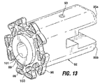
図13は、アンビルハウジング30から分離したアンビルサポート92を示す。アンビルサポート92の遠位部分は、上プレート95aと下プレート95bに分離される。プレート95aは、プレート95bの同様の穴と同軸である穴93を有する。アンビルサポート92の近位部分はアンビル96を支持する。図14に示すように、アンビル96は、ステープルがステープルカートリッジから打ち出されると各ステープルの脚がくぼみ98と係合するような位置とされた複数のくぼみ98を含み、くぼみ98によりステープルの脚は折り曲げられまたは丸められる。図示の実施の形態では、アンビルは、2つの環状リングのオフセットしたステープル、各リングに5つのステープルを有するステープル配列向けに設計される。中心開口97はアンビル96を貫通し、アンビルサポート92の内腔と隣接する。
FIG. 13 shows the
アンビル96とステープルカートリッジ78(図7)は、ステープル固定される組織に力を掛ける、ステープラヘッドの2部分である。図9と図14に示すように、好適なアンビルとカートリッジは、アンビル96のくぼみ98とカートリッジ78のステープル位置80を取り囲む材料を最少量使用するように設計され、組織に接触するアンビル/カートリッジ表面積をできるだけ小さくする。一定の力が作用した場合、組織のより小さな領域がアンビルとカートリッジで押されることになるので、より小さな接触面積は、大きな接触面積が与えるよりも小さなダメージしか組織に与えない。しかし、力がより狭い領域に分散するので、押されている組織は、与えられた力からより大きな圧力を受ける。別の言い方をすると、最少の接触面積は、小さな力でより大きな圧力を組織に生ずる。このことが、機械的観点から有利であるのは、ステープラヘッドが、より大きな接触面積のカートリッジとアンビルで必要となるような大きな力を供給したり、その力に持ちこたえる必要がないからである。
図7を参照して、図示の実施の形態では、ステープルカートリッジ78は、その中に収容されたステープルの輪郭をなぞる外壁を有し、よって、外側ステープル位置あるいはスロット80aを取り囲む複数個のペダル73を形成し、内側ステープル位置80bに隣接して、ペダル間には溝79が配置される。各ステープルの位置がカートリッジの材料で完全に囲まれるようにするよりは、ステープル位置80a、80bはそれぞれ、後壁71aと、該後壁に付けられる保持要素であって、ステープルを保持要素と後壁で保持するような位置となされた保持要素を含むのが好ましい。図7では、保持要素は、後壁71から内側に曲がる1対の翼状部位71bを備え、ステープルをステープル位置内に保持するように十分に境界を示すが、周囲全体の境界を示さない方が好ましい、スロットを画定する。アンビルは、図13に示すように、同様のペダル配置を有する。
Referring to FIG. 7, in the illustrated embodiment, the
再び図13を参照すると、プレート99がアンビル96に配置され、組織をカッティングする間、遠位に進んだカッティング要素86はプレート99と接触するように進む。一実施の形態では、プレート99は、アンビルの開口97内に置かれる。「カッティングボード」とも称されるプレート99は、捕捉した組織の圧力を解放し、パンチとプレートが閉じられたボリュームを生成する状態である流体圧固着を防止する穴101を有する。接触後にカッティング要素86を動かそうとすると、圧力がこの閉じられたボリューム内部で上昇し、さらなる動きに対する抵抗となるであろう。このことにより、組織カッティングを防止し、または、悪影響を及ぼす。
Referring again to FIG. 13, while the
カッティングボードは、カッティング要素86の進みに対して硬い停止作用を及ぼさないように設計されることが好ましい。カッティング要素86がカッティングボードで止められると、ステープルピストンもまた止められ、不完全なステープルの形成となりうる。したがって、カッティング要素86は、組織をカットする間またはその後、カッティングボードに侵入しまたはカッティングボードを動かせることが好ましい。すなわち、カッターは、カッティングボードと初めて接触しても、僅かに前進することができる。
The cutting board is preferably designed so that it does not exert a hard stop action on the advancement of the cutting
図15Aおよび図15Bは、異なった実施の形態のカッティングボードと接触するように進んだカッティング要素86を図示する。図15Aの実施の形態では、カッティングボード99aの材料は、弾性シリコーンなどの比較的柔らかい材料であり、図示するように、進むカッティング要素が切り、または、侵入する。この材料は、ステープル形成の最終ステージにて、カッティング要素の鋭利な遠位端がカッティングボード内に動くことを可能にする。図15Bの実施の形態では、カッティングボード99bは、その背後に弾性スプリング99cのような圧縮できる物と一緒に配置された堅い材料で作ることができる。当該図では、このスプリングはOリングである。カッティング要素86がカッティングボード99bにぶつかって前進することにより、カッティングボードはスプリング99cに接して遠位方向に変位する。前進するカッティング要素86は、Oリングが圧縮されるにつれ、大きくなる抵抗を受ける。コイルワイヤ、スプリングワッシャ、板バネのような他のスプリング形状および材料を用いて、同様の結果を得ることもできる。カッティングボード99bの表面の面取り面99dは、カッティング要素86がカッティングボードと接触するようになされるとき、カッティング要素と軸合せするのに役立つ。
FIGS. 15A and 15B illustrate a cutting
[アームアセンブリ]
アームアセンブリ32の特徴を以下に説明する。図16は、ステープラヘッドの他の要素から分離されたアームアセンブリ32を示す。一般的に、各アームアセンブリは、ステープルハウジングに旋回可能に連結された第1アームセクション100と、第1アームセクションとアンビルハウジングの間に旋回可能に連結された第2アームセクション102とを有する。図示の実施の形態では示されないが、第1アームセクションと第2アームセクションの間に追加のアームセクションを配置してもよい。
[Arm assembly]
The features of the
すなわち、各アームアセンブリは、互いにジョイントされてヒンジ104を形成する近位アーム100と遠位アーム102を含む。近位アーム100のそれぞれは、長手方向切抜き108と、その切抜き108内に旋回可能に取り付けられるアームスプレッダ113を有する。各アームスプレッダ113の遠位端は、穴112を含む。ピン84が、穴112内に配置される。図10に関連して開示されるように、このピン84は、ディスク68を貫通して延在し、ステープルハウジングの上部分および下部分のスロット64(図6)内をこれに乗って進む端部を有する。よって、ステープルハウジング内のディスク68の長手方向の動きは、対応するスロット64内でピン84を進ませ、アームスプレッダ113をピン84に関して旋回させ、アームアセンブリ32を外側に駆動する。アームアセンブリ32の動きに関する他の詳述は、「ステープラヘッド動作」と題する章で説明する。
That is, each arm assembly includes a
アームアセンブリの遠位アーム102は、説明したように、アンビルハウジング30(図4)に旋回可能に取り付けられるピン36を含む。一対の駆動リンク114を備え、それぞれの駆動リンクは、遠位アーム102の対応する1つに旋回可能に付けられる第1端部と、共通ピン116に旋回可能に連結される第2端部とを有する。組み立てられたステープラヘッドでは、ピン116はアンビルサポートの上プレート95aと下プレート95bの穴93(図12のプレート95a、95bを参照)に配置される。下記のステープラヘッド動作の章で詳述するように、アームスプレッダ113がアームアセンブリ32を外側に駆動するとき、駆動リンク114はピン116に作用してアンビルサポートを近位方向に押し、アンビルをステープルカートリッジに向けて近位方向に進ませる。
The
あるいは、アンビルを、アームアセンブリとは独立して、アンビルハウジングに支持された直接の流体圧駆動機構により、ハウジング内で駆動してもよい。好ましくは、ステープルホルダとアンビルが同時にそれぞれのハウジング内で互いに向けて動くように、2つのハウジング内の駆動機構を調整する。 Alternatively, the anvil may be driven within the housing by a direct hydraulic drive mechanism supported by the anvil housing, independent of the arm assembly. Preferably, the drive mechanisms in the two housings are adjusted so that the staple holder and the anvil simultaneously move toward each other in the respective housings.
[ステープラヘッド動作]
以下の説明では、アームアセンブリが、真空チャンバを拡張し、吸引によりチャンバ内に引き込んだ組織を圧縮する機能を果たす方法に焦点を当てる。チャンバの膨張に先立つ最初の工程として、ステープラヘッドを、膜24の開口26がひだの形成を所望する位置の組織と接触するように配置する。真空源20(図2)を起動し、膜により画定される真空チャンバの内部を真空にする。開口26と接触する組織(図3B)を、ステープルハウジング28とアンビルハウジング30の間の真空チャンバ内に引き込む。組織を引き込んだ後、ステープラの外形を変化させ、膜内でチャンバの容積を拡張する。
[Stapler head operation]
In the following description, the focus is on how the arm assembly serves to expand the vacuum chamber and compress the tissue drawn into the chamber by aspiration. As an initial step prior to chamber expansion, the stapler head is positioned so that the
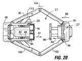
拡張する前のステープラヘッド28の細くした位置を図4、図17および図18に示す。特に、ヒンジ止めされたアームアセンブリ32および膜ライザ37は該して直線方向である。近位アーム100は、チャンバ拡張と組織圧縮用の駆動アームとして機能を果たす。圧力下の水がステープルハウジングの流体圧回路中に流し込まれると、これらのアームの動きが始まる。図19を参照して、流体圧はディスク68を前進させる(図19には図示されない圧縮ピストン106の動作により)。次にディスク68は、図19〜図21に示すようにステープルカートリッジ78をアンビル96方向に押し、ステープルカートリッジ78をステープルハウジング28からさらに伸ばす。
The narrowed position of the
ディスク68とアームスプレッダ113はピン84に連結される。このため、ステープルハウジング28内のディスク68の長手方向の動きは、対応するスロット64内でピン84を遠位に動かす。アームスプレッダ113は結果としてピン84に対し旋回し、近位アーム100を外側に駆動する。ヒンジ104位置での近位アーム100の外側への動きは、遠位アーム102もヒンジ位置で外側に旋回させ、近位アーム100と遠位アーム102の間に角度を形成する。当然ながら、近位アーム100と遠位アーム102の間に角度が形成されると、それらのアームの離間した端部間の有効長さを短くし、遠位アーム102の遠位ピン36によりアンビルハウジング30をステープルカートリッジ方向に動かす。遠位アーム102の旋回の動きはさらに、駆動リンク114がピン116に作用してアンビルサポートを近位方向に押させる。このことは、アンビルハウジングが近位方向に動くのと同時に、アンビルハウジングに関してアンビルサポートを近位方向に動かす。
The
要するに、一つの動き、すなわち流体圧駆動の圧縮ピストンの動きが、図19〜図21で矢印A1、A2、A3として図示される少なくとも3つの動きを生成する。これら3つの動きには、ステープルカートリッジ78のステープルハウジングに対するアンビル96方向への動き(矢印A1)、アンビルハウジング30のステープルハウジング28方向への動き(矢印A2)、および、アンビル96自体のアンビルハウジング30に対するカートリッジ方向への動き(矢印A3)を含む。ステープルカートリッジ方向へのアンビルのこの合成した動きは、圧縮ピストンの小さな変位が、ステープラで掴まれた組織をすばやく圧縮できるようにする。動きの増大はまた、近位(被駆動)アームと遠位(駆動)アーム間の、ヒンジ104位値の角度、をできるだけ大きくすることにより、2つのハウジング間の力の伝達を高める。
In essence, one movement, ie, the movement of a hydraulically driven compression piston, produces at least three movements illustrated in FIGS. 19-21 as arrows A1, A2, A3. These three movements include the movement of the
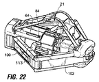
2つのハウジングの互い方向への相対的な動きはまた、ステープラヘッド14の上部の上方リンク38、40およびそれらを繋ぐスプリングワイヤ46を駆動する。一緒に、そのリンクとワイヤは膜の上部を持ち上げ、圧縮中に拡大した組織を収容するより大きな容積を生みだす。
The relative movement of the two housings in one direction also drives the
図22〜図24に示すように、ステープルハウジング28のスロット64を移動するピン84が移動の限界に達したときに、組織の圧縮は停止する。よって、スロットと関連する部品の大きさは、ステープラヘッドのステープラ側とアンビル側での組織接触面間に所望の離間距離を設定するような大きさとされる。胃壁のひだ形成で用いられる一例としての離間距離は、概略、0.06〜0.07インチ(1.52〜1.78mm)(たとえば、5.5mmの長さの脚を有するステープルを用いる場合)または6.5mmの脚の長さのステープルでは0.109インチ(2.77mm)である。流体圧回路にさらに圧力を掛けても、それ以上は組織を圧縮しない。
As shown in FIGS. 22-24, tissue compression stops when the
さらに、ピストンの配置のため、ステープルの機能は、組織の圧縮が終了するまで、効果的にロックアウトされる。この配置により、組織の圧縮の終了前に流体ポート50b(図11A)からステープル流体経路122内に導かれた流体は、圧縮ピストン106の2つのOリング112が入口114を挟んだ位置になるまで、流出する。この設計により、早過ぎるステープルの打ち込みを防止する。
Furthermore, because of the piston placement, the staple function is effectively locked out until the tissue compression is finished. With this arrangement, the fluid introduced from the
完全に圧縮した位置で、アームスプレッダ113は、ステープラヘッドの長手中心軸とほぼ直角となる。組織がカートリッジ78とアンビル96との間で圧縮されると、組織はステープル固定される準備が整ったことになる。
In the fully compressed position, the
ステープル固定は、流体圧流体をポート50b(図5)を通じて導き入れることから始める。ステープルピストンが進み、カッティング要素86(図7および図10)をアンビル96方向に押す。ステープルプッシャ76がカッター86に取り付けられているので、この動きは、ステープルプッシャ76をカートリッジ78を通って動かし、同時に全てのステープルを組織を通過して押し進める。ステープルピストンの移動は、内部の止め具により制限され、最適なステープル形状を生ずるようにプリセットされる。
Stapling begins with the introduction of hydraulic fluid through
圧縮する間、アームアセンブリ32のヒンジ104の角度がその最小値に達すると、ステープルハウジングとアンビルハウジングの分離に抵抗するのに必要な力が増加する。ステープルピストンによりステープルをつぶす力がアンビルに作用すると、このような力はさらに増加する。相殺するために、アームスプレッダ113は、少なくともこれらの力の一部をディスク68に導く変位ストラットとして機能する。押しているディスクから抵抗されないと、これらの力は、アーム100、102を引き込み、潜在的に組織の圧縮を解放し、不完全なステープル形成または組織カッティングの結果となる。このように、トラスのような構造が力変位に対して生ずる。
During compression, when the angle of the
ステープルが形成されると、ステープルの圧力が解放され、スプリング(不図示)がステープルプッシャ72をその基本位置に戻す。流体圧を解放すると、膜ライザ37上の変形したスプリングワイヤ46がステープラヘッドを最小輪郭形状に戻し、ひだをステープラから解放する。患者の外に出ると、使用したステープルカートリッジは取り出され、新しいものが入れられる。
Once the staple is formed, the staple pressure is released and a spring (not shown) returns the
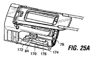
図25A〜図25Cはステープルハウジング内の取り外し可能なステープルカートリッジを保持する一方法を図解する。カートリッジは、ステープルハウジングにスプリング止めされ、それぞれ支点172に関して旋回可能な2つのラッチ170(1つしか見えない)で保持される。図示するように、支点172はピン84によりディスク68に連結される。それぞれのラッチ170は留め金174を含み、留め金174はカートリッジの対応する留め金176と係合する。ラッチ170は、ばね付勢されて留め金174をカートリッジ方向に内側に押すことが好ましい。
25A-25C illustrate one method of retaining a removable staple cartridge within a staple housing. The cartridge is spring-loaded to the staple housing and held by two latches 170 (only one is visible), each pivotable about a
図25Bで矢印Pにより示されるように、各ラッチ170の近位端175を押圧することにより、この付勢に抗してラッチを旋回させ、ステープルカートリッジを取り出す。図25Cに示すように、新しいステープルカートリッジを、溝79を軸合せ棒74と合せて配置し、それからステープルハウジング方向に押す。新しいカートリッジを所定の位置にスライドさせると、留め金174が、留め金176のテーパの付いた近位部分178を乗り越える。留め金174が留め金176の遠位端180を越えると、ばね付勢のためにカートリッジ方向内側に落ち、カートリッジと係合する。カートリッジが正しく位置するとき、ラッチが新しいカートリッジと係合するとクリックが知覚できあるいはクリック音が聞こえる。
Pressing the proximal end 175 of each
[ステープル固定中のステープラ配置]
動作中、2つのステープラ部材がくっつけられると、組織の折り目がステープルカートリッジとアンビルの対面する面の間で捕捉される。組織の折り目のステープル固定の直前若しくはステープル固定の間に、この組織の捕捉が生ずると、捕捉された領域の組織の厚さおよび/または圧縮性の変動は、ステープル操作を中心からずらす、すなわち軸がずれるようにバイアスを掛け、ステープルの脚を関連するアンビルのくぼみ内で正しい位置から外れて受けられるようにし、たとえば、ステープルの脚が完全に折り曲げられない、および/または、ステープルの配列が装置の中心軸からずれるなど、1つ以上のステープルが不完全に固定する結果となり、たとえばいくつかのステープルがステープル固定された折り目の中心に開けられた孔に近くなりすぎる。
[Stapler placement during staple fixing]
In operation, as the two stapler members are brought together, tissue folds are captured between the facing surfaces of the staple cartridge and the anvil. When this tissue capture occurs immediately prior to or during stapling of tissue folds, variations in tissue thickness and / or compressibility in the captured region will cause the stapling operation to be offset from the center, i.e. the axis. Biased so that the staple legs can be received out of position in the associated anvil recesses, for example, the staple legs are not fully folded and / or the arrangement of staples is a device One or more staples may be incompletely fixed, such as off of the central axis of, for example, some staples too close to the hole drilled in the center of the stapled fold.
カートリッジの各ステープル配列(たとえば、それぞれ5つのステープルの2つの同軸な配列)について上手くステープル操作が行われることを確かにするため、本発明の装置は、軸合せ構造を含み、ステープル固定動作の直前およびその間に装置の遠位部材と近位部材を軸合せした状態に保持する。軸合せ構造は、図36および図37の側面断面図に示す。図36には、遠位部材27にアンビル96とカッティングボード99aを、近位部材25にカッター86を含むステープラ装置12の一部を示す。操作では、2つの部材と、これらに支持されるステープルカートリッジとアンビルは、最初は一緒に動かされ、図22および図23に図示するように、カートリッジとアンビルの対面する面の間に組織の折り目を捕捉する。その後、図24に示すように、ステープルピストン116は、縮んだ位置から伸びた位置へ動かされ、図示のようにカッティングボード99aに対してカッターを動かし、ステープルカートリッジのステープルをアンビルに対して駆動する。
In order to ensure that the stapling operation is successful for each staple array of the cartridge (eg, two coaxial arrays of 5 staples each), the apparatus of the present invention includes an alignment structure and immediately prior to the staple fixing operation. And in between, the distal and proximal members of the device are held in alignment. The alignment structure is shown in the side cross-sectional views of FIGS. FIG. 36 shows a portion of the
軸合せ構造は、カッター86内で動くように軸方向に保持されたピンと、アンビル96内で軸方向に動くように取り付けられたハウジング27の部分に支持されたブッシュ164に形成されたピン受容スロットを含む。図36に示す実施の形態では、ブッシュ164は、ハウジング27内でスプリング166によりブッシュ方向のピンの動きに抵抗する方向にばね力をかけるようになされ、カッターと捕捉された組織を貫通している付属のピンがブッシュの面取りした端部に当たるようにする。カッター、ピンおよびステープルプッシャが第2部材方向に動き続け、最終的に組織に穴を形成し、ステープルカートリッジから組織を貫通してアンビルに対してステープルを打ち出すとき、2つの装置部材は軸合せされた状態を維持し、ステープル固定操作は、全てのステープルが関連するアンビルのくぼみに関して軸合せした位置で行われる。この操作が終了するとき、ステープルピストンと駆動部材は縮んでステープル固定された組織を解放し、装置を直線状の状態に戻す。
The alignment structure includes a pin receiving slot formed in a
図37に示す装置12の実施の形態は、上記で説明した装置に類似するが、カッターのハウジングに支えられた軸合せピン168がスプリング174により、第2部材の方向でばね付勢され、ピン受容スロット170が部材27のアンビル(不図示)の下で支えられる固定位置のブッシュ172にある。この実施の形態では、ピンが初めにブッシュのスロット内に置かれると、2つの部材の互い方向への動きは、ステープルピストンが完全に伸びた位置方向に動き続け、上記のように、2つの部材間で組織をカットしステープル固定するように、第2部材から離れる方向のピンの動きにより調整される。
The embodiment of the
[ステープラシャフトおよびハンドル]
再び図2を参照すると、ハンドル18とステープラヘッド14とを接続するステープラシャフト16は、上部消化管の曲がりに適合するのに十分な柔軟性を有するが、ステープラヘッドを回転するのに足りるトルクを伝達する性能を維持する。シャフトは、食道のガイドチューブ23内を押し下げられるのに十分な剛性を持って形成される。適切な材料としては、次のものがある。
[Stapler shaft and handle]
Referring again to FIG. 2, the
図26は、シャフトからステープラヘッドを取り除いた、シャフト16の遠位部分を示す。図示のように、シャフト16は、内視鏡が中を通りステープル操作を観察するための内視鏡内腔124を含む。側部内腔126をまた、作業中に有用な他の器具を受容するために備える。
FIG. 26 shows the distal portion of the
接合部128は、シャフト16とステープラヘッド14の間の、シャフト16の遠位端に位置し、ステープラヘッドがシャフトに対して接合される。真空源と流体圧流体源に接合されるチューブ類は、ハンドルからシャフト16および接合部128を通って延在する。
The joint 128 is located at the distal end of the
図27Aは、流体圧流体ライン130に使用される1つの形態を示す。使用中、流体圧流体ラインは、ステープラの接合部での大きな変形と伸びにさらされる。また10.3MPa(1,500psi)を超えるような流体圧にも時々さらされる。産業向けの流体圧流体ラインは、柔軟で、使用中の長さの変化に順応する追加チューブの作動ループを有するのが普通である。流体圧流体ラインの図示の形態は、空間的制約のある内視鏡装置に特に適した小形の解決法である。好適な流体圧流体ラインは、曲げられるときに有効長さの変化に順応するように、長手方向に伸びる形状とされた部分を有するチューブ130である。チューブの長手方向に伸びる部分は、ステープラ12の接合部128内に配置されるのが好ましい。好適な設計では、長手方向に伸びる形状は、図27Aに示すようにコイル形状である。代替の実施の形態では、チューブ130は、規則的な若しくは不規則な波形のような他の長手方向に伸びる形状に形成されてもよい。
FIG. 27A shows one configuration used for the
チューブ130に好適な材料はステンレス鋼ハイポチューブであるが、他の材料を代わりに用いてもよい。好適なステープラの構成では、組織圧縮を作動するものと、ステープル用途(および使用時にカッティングする)のものと、2つの駆動流体ラインを備える。本実施の形態では、図27Aに示すようにそれらのチューブは一緒にコイルに巻かれる。代替の実施の形態では、2つ以上のコイル状チューブが一のコイルが他のコイルの内側に入る入れ子状になってもよい。接合部が曲がると、コイルチューブを曲げ、曲げの結果として長さを変化させる。コイル状チューブは、このような動きの間のコイル状ワイヤと同様に挙動し、よって、チューブの内腔を通る流れを低下させたり流体圧システムの何れの端部の接続部に過度の応力を生じさせたりすることなく、長さを変え、変形し、接合部の輪郭に追随できる。
A suitable material for
流体圧流体ライン用の長手方向に伸びる形状は、内視鏡装置の関節接合または曲げ部を通して治療薬や潅注流体を運ぶカテーテルや内視鏡装置などの、他のタイプの関節接合医療装置の操作端部に流体を運ぶ使用にも適している。 The longitudinally extending shape for the hydrostatic fluid line can be used to manipulate other types of articulating medical devices, such as catheters or endoscopic devices that carry therapeutic agents or irrigation fluid through the articulation or bend of the endoscopic device Also suitable for transporting fluid to the end.
再び図26を参照すると、接合部128は、一対の引張りケーブル134(図26では、1本だけが示される)上に並べられた複数のリンク132で形成された背骨状のものからなる。一実施の形態では、引張りケーブルの関与により、ステープラヘッド14は一方向での約90度(図3B参照)から反対方向での175度(図3C参照)の範囲の動きにより2方向に接合できる。引張りケーブルはそれぞれ、ステープルハウジング28の最遠のリンク132位置のような、ステープラヘッドの位置またはその近くで固定される。
Referring again to FIG. 26, the joint 128 consists of a spine formed of a plurality of
引張りケーブル134の最近部分は、シャフト16の長さにわたって延在し、ハンドル18に終端を有する。図28を参照すると、ハンドル18は、時計回りまたは反時計回りに選択的に回転し、ステープラヘッドを上下に接合する回転ノブ136を含む。一方向への回転により引張りケーブルの1本にテンションを掛け、ステープラヘッドを下方に曲げ、反対方向への回転は他のケーブルにテンションを掛け、ステープラヘッドを上方に曲げる。
The proximal portion of the
好適なハンドルの構成では、ノブ136は、内ねじ穴138を含む。ノブ136は、ハンドル内に固定されるが、自由に回転できるように、ハンドル18内に部分的に拘束される。ねじ付き外面を有するカートリッジ140をノブの内ねじ穴138に配置する。内ねじ穴138内のねじは、カートリッジ140のねじと螺合し、ノブの回転によりカートリッジは、ハンドル内で平行移動するが回転はしないようにする。
In the preferred handle configuration, the
図28でケーブル134aと134bとした2本の引張りケーブルのそれぞれは、ハンドルの別の部材で終端処理される。ケーブル134aはスライドするキャリッジに取り付けられ、ケーブル134bはハンドル18の不動部分に取り付けられる。各ケーブルは対応する鞘を通って延在する。ケーブル134bは、ハンドル18の不動部分に固定された近位端を有する鞘135b内に延在し、ケーブル134aは、スライドするキャリッジに取り付けられた近位端を有する鞘135a内に延在する。
Each of the two tension cables, shown as
ケーブル134a、134bと鞘135a、135bは、キャリッジの一方向での平行移動がステープラヘッドの一方向での変形を引き起こし、キャリッジの他方向での平行移動がステープラヘッドの別方向での変形を引き起こすように配置される。
The
図28を参照して、ノブ136が回転してキャリッジ140を図中の左方向に移動させたとすると、ケーブル134aにテンションが掛かり、ケーブル134bは緩み、ステープラヘッドを第1方向(たとえば上方に)に関節で曲げる。反対方向のノブ136の回転によりキャリッジは図中右方向に進み、ケーブル134aのテンションを解放し、鞘135bをケーブル134b上でステープラヘッドの遠位端方向に押し、鞘135bがシャフト16の遠位部分に対して進むにつれ、関節接合を第2方向(たとえば下向き)にする。鞘135bの近位部分には十分な作業長さが与えられ、キャリッジが遠位方向に動くときに鞘135bにテンションが掛からないようにする。ノブの位置決めは、ステープラを関節で曲げるのに必要な手の動きが、ステープラの回転方向に関わらず、常に一定という利点がある。また、ねじ付きノブを使うことで、ノブに回転方向の位置を維持するためのロックが備えられなくても、変位角が意図せずに緩むことを防止する。
Referring to FIG. 28, if the
図28と図29を参照すると、内視鏡内腔124はステープラの中心軸に沿って延在する。内腔の位置決めおよび内視鏡124に対して関節接合ノブが同軸であることとにより、内視鏡とステープラとは、互いに干渉することなく独立して回転することができる。よって、ユーザが本体内でステープラヘッド14の回転方向を変更することを選択すると、内視鏡の回転位置を維持しつつ、ハンドル18とシャフト16を回転できる。
Referring to FIGS. 28 and 29, the
コスト効率のために、ステープラ12を、ステープラヘッド14を廃棄でき、シャフト16とハンドル18を消毒して再使用できるように設計してもよい。ステープラヘッドをシャフト16に対し取り外し可能に連結する一つの機構を図示するが、他の機構も容易に考案できる(たとえば、スリップタイプの配置)。図26を参照して、エンドプレート142はリンク132の最遠位のものに取り付けられる。エンドプレート142とステープラヘッドの対応する背面はそれぞれ、エンドプレートとステープラヘッドとが互いに係合できるラッチ機構を備える。
For cost efficiency, the
エンドプレート142は、ペグ145(ばねピンでよい)を有する片持ち梁ピン144、中心開口146および縁に沿った一対のU字留め金若しくは係合エッジ148を含む。流体圧流体供給穴または開口156a、156bをエンドプレート142を貫通して形成する。流体圧流体をステープラヘッドに運ぶ流体圧流体チューブ(図27のチューブ130参照)はエンドプレートに溶接され、チューブからの流体が流体圧流体供給穴156a、156bを通って流れるようにすることが好ましい。
The
図30Aと図30Bは、ステープルハウジングの背面48aを示すが、図5に対して多少変形させてある。背面48aのこの変形では、流体圧流体インプットポートまたは開口50a、50bは、図示のように再配置されている。さらに、背面48aは、アンダーカットボス150の形で一対の留め金または係合エッジを含み、加えて、軸合せピン152および孔154を含む。シャフトのステープラ装置へのスナップ式接続:
30A and 30B show the
図30Aおよび図30Bは、ステープルハウジングの背面48aに向かい合って配置されたエンドプレート142を示す。接合部128の他の特徴は、明確化のために図30Aおよび図30Bには示さない。ステープラヘッドをシャフト16に取り付けるために、ハンドルアセンブリに取り付けられたエンドプレート142を、図30Aに示すように、ステープルハウジングの背面48aに対して押圧する。エンドプレート142が押されると、時計方向に回転し、片持ち梁ピン144のペグ145(図26)をステープルハウジングの背面の孔154に係合する。このラッチが係合するとき、エンドプレート142の流体圧流体供給孔156a、156bは、図30Bに示すように、ステープラヘッドの流体圧流体インレット50a、50bと重なる。同時に、U字留め金148を囲むエンドプレートの部分はアンダーカットボス152の下でスライドする。エンドプレートを雄会うことにより、流体圧流体インプットポート50a、50bを取り囲む、面をシールするOリングを圧縮する。Oリングの圧縮は、エンドプレートに張り出すアンダーカットボスと留め金の係合により維持される。ステープラヘッドをハウジングから取り去るために、ステープルハウジングを反時計方向に捩り、エンドプレート142を背面48aから外す。それから、新しいステープラヘッドを取り付ける準備として、ステープラシャフトとハンドルを消毒してもよい。
30A and 30B show the
[例示的手順]
図31〜図33を特に参照して、次に胃壁組織にひだを形成する状況でシステム10を使用する方法の一例を説明する。
[Example procedure]
With particular reference to FIGS. 31-33, an example of a method for using the
最初の工程として(図2)、内視鏡のガイドチューブ23を口と食道を経由して胃に進ませる。内視鏡22を、ステープルハンドル(不図示)の内視鏡チャンネルに挿入し、ステープラハンドルの内腔内で下に進める。ステープラ/内視鏡は、同時に内視鏡のガイドチューブを通って胃に送られる。ステープラと内視鏡が胃の食道胃接合部位に到達すると、ステープラの位置は留まり、内視鏡は胃の中にさらに進む。
As the first step (FIG. 2), the
ステープラヘッド14を、胃の中の所望の深さおよび場所に進ませる。ステープラハンドルの関節接合コントロールを用いて、ステープラヘッドの角度方向を調節し、図31Aに示すように、事前決定した対象組織にステープラヘッド12を位置決めする。膜24の開口26を対象組織に接触した位置とする。内視鏡22を、図示のように反り返った位置とする。
The
真空源20(図2)を、体外のハンドルの真空ポートに連結し、図31Bおよび図32Aに示すように、真空圧を掛けて組織17を開口26を通って膜24で画定された真空チャンバ内に引き込む。対象組織を捕捉したことは、ステープラヘッドの透明な膜24の壁を通じて内視鏡的に容易に確認できる。
A vacuum chamber in which the vacuum source 20 (FIG. 2) is connected to the vacuum port of the extracorporeal handle and
流体源(図示)をハンドルに連結する。十分な量の組織を捕捉したことが視覚的に確認できたならば、流体圧流体を導入して、図32Bおよび図31Cに示すように、組織を圧縮し、アームアセンブリ32と膜ライザ37を広げる。図から分かるように、アームアセンブリと膜を広げることにより、大きな体積の組織を真空チャンバ内に捕捉し、組織を圧縮している間さらにチャンバ内に変位することができる。前に述べたように、操作中に組織を広がったチャンバ内に、図32Bおよび図32Cのステープルホルダとアンビルよりかなり「上方に」引き込むことにより、組織のステープル固定された部分の周囲に比較的大きな組織のマージンが得られ、組織のステープル固定された部分の近くで組織が破れたり組織の折り目が弱くなったりするリスクを低減する。捕捉された組織の折り目を17aとして示す。
A fluid source (shown) is connected to the handle. If it can be visually confirmed that a sufficient amount of tissue has been captured, hydraulic fluid is introduced to compress the tissue, as shown in FIGS. 32B and 31C, and the
組織が圧縮されると、さらに流体圧流体を導入して、図31Dと図32Cに示すように、組織のステープル固定を行い切り込みを入れ、図33で17として示されるひだPを形成する。その後、圧縮とステープル固定用の流体圧源を停止して、流体圧回路内の流体圧力を解除する。流体圧力が解除されると、膜ライザ37のスプリングワイヤがステープラヘッドを元の流線形の形状に戻すのを助け、図31Eに示すようにステープラヘッドを組織から引っ張り出せるようにする。ステープラヘッドはシャフトに関して関節で曲げられステープラヘッドをひだPから離すのに役立つ。
As the tissue is compressed, more hydraulic fluid is introduced to staple and cut the tissue as shown in FIGS. 31D and 32C to form pleats P, shown as 17 in FIG. Thereafter, the fluid pressure source for compression and staple fixing is stopped, and the fluid pressure in the fluid pressure circuit is released. When the fluid pressure is released, the spring wire of the
図33に示す好適なひだ形状では、ステープル158は、ステープルで保持されたステープル補強具83付きの、5つのステープルの2つの同心のリングに配列され、図示のステープルパターンの周りに力を分散する。ひだPは、カッティング要素で形成された孔Hを含み、孔Hを介して種々の埋め込みまたは種々の埋め込み用のアンカを取り付けることができる。
In the preferred pleated shape shown in FIG. 33, the
複数のひだが必要な場合には、ステープラ12を内視鏡のガイドチューブから少しの間引き出して、図25A〜図25Cに関連して説明した方法によりステープルカートリッジを取り替える。すべての所望のひだが形成されるまで、上記手順を繰り返す。
If multiple pleats are required, the
このシステムは、本書で開示した方法を用いるステープル固定手順を実施するために開示した種々の特徴を用いるようにユーザに説明する使用説明と共に梱包されるとよい。 The system may be packaged with instructions for use by the user to use the various features disclosed to perform the stapling procedure using the methods disclosed herein.
[代替の実施の形態]
上記に開示したステープラの基本的な構造は、他のステープル固定ツールの基礎として使うことができる。図34および図35は、膜と膜ライザを取り除いた、改変したステープラを示し、そのステープラでは、ステープルハウジング28はツールの取り付け用に改変される。図34に示すように、ステープルハウジング28は、ツール162を受容するように釣り合いを取った一対の溝160を含む。ツール162は、これらの溝160に置かれ、図35に示すようにステープルハウジングに取り付けられる。この取り付けは、そこからツールを動かす固定ベースを提供する。ツールは、それ自体が関節で曲げられてもよく、または、体腔に組み立てたものを挿入するための細くした位置と図35に示すような展開した位置との間でツールを動かす装置164をステープルハウジング28に備えてもよい。図35に示すものに類似したツールをカートリッジとアンビルの間で伸ばすことにより組織捕捉に用い、組織とかみ合い組織をカートリッジとアンビルの間の位置に引くのに用い、組織をステープル固定し、または、アンビルとカートリッジに加えもしくは別の場合には種々の機構により別の処理をしてもよい。本ステープラの適用の利益を得る手順には、胃形成、瘻孔調節、ポリープ切除、リード設置法、出血コントロール、穿孔または孔閉止、バイオプシ、腫瘍除去が含まれるが、これらには限定されない。
[Alternative embodiment]
The basic structure of the stapler disclosed above can be used as the basis for other staple fixing tools. FIGS. 34 and 35 show a modified stapler with the membrane and membrane riser removed, in which the
開示のシステムは、開示した圧縮とステープル固定作用を実施するのに便利な実施の形態を提供する。しかし、多くの他の広範に変化する器具やシステムを、本発明の範囲内で、代わりに用いてもよい。さらに、開示した実施の形態の特徴を、種々の方法で互いに組み合わせまたは他の特徴と組み合わせ、追加の実施の形態を生成してもよい。よって、本書で説明した実施の形態は、内視鏡の組織ひだを形成するのに用いるシステムの代表例として取り扱うものであり、特許請求の範囲に記載した発明の範囲を限定するものとして用いてはならない。 The disclosed system provides a convenient embodiment for performing the disclosed compression and stapling action. However, many other widely varying instruments and systems may be used instead within the scope of the present invention. Furthermore, features of the disclosed embodiments may be combined with each other or with other features in various ways to generate additional embodiments. Thus, the embodiments described herein are treated as representative examples of systems used to form tissue folds of endoscopes and are used to limit the scope of the claimed invention. Must not.
上記で参照されたいかなる、そして、全ての特許、特許出願および出版物は、優先権のために基礎としたものを含め、本書に参照して組み込む。 Any and all patents, patent applications and publications referred to above are incorporated herein by reference, including those based on priority.
Claims (28)
ステープルハウジング(28)と、前記ステープルハウジングに関して独立して動かせるステープルホルダ(78)を有するステープル部材(25)と;
アンビルハウジング(30)と前記アンビルハウジング(30)に支えられたアンビル(96)を有するアンビル部材(27)と;
前記ステープルハウジング(28)内で縮んだ位置から伸びた位置に動くため前記ステープルホルダ(78)に動作可能に接続された駆動部材(68)と、前記ステープル部材(25)と前記アンビル部材(27)に動作可能に接続されたアームアセンブリ(32)を含み、縮んだ位置から伸びた位置への前記駆動部材(68)の動きが、(i)前記ステープルハウジング(28)に関して前記ステープルホルダを前記アンビル(96)方向(A1)に動かし、(ii)前記アンビル部材(27)を前記ステープル部材方向(A2)に動かすようになされた駆動アセンブリ(29)を備える;
装置。 A stapler device (14) for driving staples into tissue:
A staple member (25) having a staple housing (28) and a staple holder (78) that is independently movable with respect to the staple housing;
An anvil member (27) having an anvil housing (30) and an anvil (96) supported by the anvil housing (30);
A drive member (68) operatively connected to the staple holder (78) for moving from a retracted position to an extended position within the staple housing (28), the staple member (25) and the anvil member (27) ) Operatively connected to the arm assembly (32), wherein movement of the drive member (68) from a retracted position to an extended position (i) moves the staple holder with respect to the staple housing ( 28 ) A drive assembly (29) adapted to move in the anvil (96) direction (A1) and (ii) move the anvil member (27) in the staple member direction (A2);
apparatus.
請求項1の装置。 The anvil (96) can be moved independently within the anvil housing (30), and the arm assembly (32) is operably connected to the anvil (96) to move the drive member from a retracted position to an extended position. (68) movement is (i) moving the staple holder in the anvil direction (A1) with respect to the staple housing, (ii) moving the anvil member in the staple member direction (A2), and (iii) the anvil housing The anvil is adapted to move in the staple holder direction (A3);
The apparatus of claim 1.
請求項2の装置。 Said anvil member (27) when said drive assembly (106) is moved to a position extending from a position retracted, the arm for moving the anvil (96) to said Suthep Le holder (78) direction (A3) Including a drive link (114) operably connected to the assembly (32);
The apparatus of claim 2.
請求項1の装置。 The staple holder (78) and the anvil (96) have an abutment surface that is combined with the arm assembly (32) to define the chamber (21), and from the retracted position of the drive member to the extended position. The effect of movement is to squeeze the captured tissue in the chamber to form a captured tissue fold;
The apparatus of claim 1.
請求項4の装置。 The chamber (21) is covered with a membrane (24) and tissue can be drawn into the chamber by applying a vacuum to the membrane;
The apparatus of claim 4.
請求項5の装置。 The membrane (24) has an opening (26) for sucking tissue into the chamber on one side, and when the vacuum is applied to the chamber, the drive member (68) is extended from a contracted position to an extended position. The movement is effective to draw tissue away from the opening of the chamber;
The apparatus of claim 5.
請求項4の装置。 The drive member includes a disk (68) that moves within the staple housing (25), supports at least one pin (84) that moves within a slot (64) of the staple housing (25), and the drive member The movement range in the direction of the extended position of the pin (84) is limited to the movement range allowed for the pin (84) in the slot (64);
The apparatus of claim 4.
請求項7の装置。 Further comprising at least one arm spreader (113) pivotally connecting the disk to the arm assembly (32), and when the disk is moved from the retracted position to the extended position, the arm assembly is expanded outwardly;
The apparatus of claim 7.
前記駆動ピストン(106)内で縮んだ位置と伸びた位置の間を動くように支持されるステープルピストン(116)と、前記ステープルホルダ(78)内の1つ以上のステープルと係合するステープルプッシャ(76)であって、前記ステープルプッシャがステープルピストンと縮んだ位置から伸びた位置へ動かされると、前記1つ以上のステープルを前記ホルダから前記アンビル(96)に対して押し出すステープルプッシャ(76)とをさらに含む;
請求項1の装置。 The drive member includes a drive piston (106) connected to a disk (68);
A staple piston (116) supported to move between a retracted position and an extended position in the drive piston (106), and a staple pusher that engages one or more staples in the staple holder (78). (76) A staple pusher (76) for pushing the one or more staples from the holder against the anvil (96) when the staple pusher is moved from a retracted position to an extended position with a staple piston. And further including;
The apparatus of claim 1.
請求項9の装置。 For use with a staple holder (78) designed to hold an annular array of staples, the staple pusher (76) is designed to engage and simultaneously extrude the array of staples in the holder. Was;
The apparatus of claim 9.
請求項10の装置。 The staple holder (78) is a replaceable staple cartridge adapted to be inserted into the staple housing, together with a drive member (68) between a retracted position and an extended position within the staple housing. Moving;
The apparatus of claim 10.
請求項11の装置。 The drive member includes a disk (68) having at least one axially extending rod (84) adapted to engage the staple cartridge housed in the apparatus, the disk within the staple housing. Preventing angular movement of the staple cartridge;
The apparatus of claim 11.
請求項12の装置。 The cartridge further includes a cartridge side reinforcement ring (88) disposed in contact with the staple cartridge (78) and having an opening (85) for receiving the staple therein, the reinforcement ring (88) facing the staple cartridge. Attach to the side of the stapled tissue;
The apparatus of claim 12.
請求項9の装置。 A tissue fold attached to the staple piston (116) and held between the staple holder (78) and anvil (96) by the movement of the staple piston (116) from a contracted position to an extended position is stapled. Further comprising a tissue cutter (86) adapted to puncture the tissue fold when secured;
The apparatus of claim 9.
前記アンビル部材は、圧縮されるカッティングボード(99a、99d)を含み、前記カッター(86)は、前記ステープルピストン(116)の動きにより前記カッティングボードとの最初の接触点を越えて進むことができる;
請求項13の装置。 The stapler device (14) further comprises a tissue cutter (86),
The anvil member includes a cutting board (99a, 99d) to be compressed, and the cutter (86) can be advanced beyond the initial contact point with the cutting board by movement of the staple piston (116). ;
The apparatus of claim 13.
請求項15の装置。 The cutting board (99a) is formed of a material that can penetrate the cutter, including silicone;
The apparatus of claim 15.
請求項15の装置。 The cutting board (99d) is spring biased in a direction opposite to the movement of the cutter;
The apparatus of claim 15.
請求項9の装置。 An alignment pin (160, 168) supported on one of the staple member and the anvil member, and a pin receiving bush (164, supported on the other one of the staple member and the anvil member) 170), wherein the pin and the bushing are arranged such that movement in the extended position of the staple piston couples the pin with the bush, and thus the extended position of the staple piston (116). Holding the two members in an aligned state when the staple is pushed out by further movement to
The apparatus of claim 9.
請求項18の装置。 One of the alignment pin and the pin-receiving bushing can be retracted under a spring bias;
The apparatus of claim 18.
請求項1の装置。 Supported at the distal end of a shaft (16) that carries hydraulic fluid to the device, the staple member and the anvil member of the device are a proximal member and a distal member, respectively, and the shaft is proximal to the device. Operably connected to the member;
The apparatus of claim 1.
請求項1の装置(14)と;
近位端ハンドルと遠位端を有するシャフト(16)と;
前記シャフトの前記遠位端を前記ステープラ装置の第1の近位部材に接続する接合部(128)と;
前記ステープル部材の駆動機構に少なくとも6.89MPa(1,000psi)の圧力の流体圧流体を運ぶのに有効な、前記シャフトに内包される流体圧流体ライン(130)とを備え;
前記接合部内の前記流体圧流体ラインはコイル状またはサイン波状形状を有し、前記シャフトに関する前記装置の軸がずれる動きに順応する;
器具。 A medical device (10) for stapling stomach tissue comprising:
The device (14) of claim 1;
A shaft (16) having a proximal end handle and a distal end;
A joint (128) connecting the distal end of the shaft to a first proximal member of the stapler device;
A hydraulic fluid line (130) contained within the shaft effective to carry hydraulic fluid at a pressure of at least 6.89 MPa (1,000 psi) to the drive mechanism of the staple member;
The hydrostatic fluid line in the joint has a coiled or sine wave shape to accommodate movement of the device relative to the shaft;
Instruments.
請求項21の器具。 The joint (128) has a spine (128) formed of a plurality of links (132) formed in a coiled or sine wave portion of the hydraulic fluid line (130);
The instrument of claim 21.
請求項21の器具。 The stapler device includes a fluid pressure driven drive member (68) and a fluid pressure driven staple piston (116), and the shaft (16) and the joint (128) include the drive member and the staple. Supporting separate hydraulic fluid lines for the pistons, the hydraulic fluid lines (30) having a coil shape that alternately overlaps within the joint;
The instrument of claim 21.
第1部材(25)であって、ハウジング(28)と前記第1部材のハウジング内を独立に移動する第1組織接触プレート(78)を有する前記第1部材(25)と;
第2部材(27)であって、ハウジング(30)と前記第2部材のハウジング内を独立に移動する第2組織接触プレート(96)を有する前記第2部材(27)と;
前記第1組織接触プレート(78)に動作可能に接続され、前記第1部材のハウジング(28)内を縮んだ位置から伸びた位置に動く駆動部材(68)と、第1部材(25)および第2部材(27)に動作可能に接続されたアームアセンブリ(32)を含み、前記駆動部材(68)の縮んだ位置から伸びた位置への動きが、(i)前記第1部材のハウジング内の前記組織接触プレート(78)を前記第2組織接触プレート(96)方向(A1)へ動かし、(ii)前記第2部材(27)をステープル部材方向(A2)に動かす、駆動アセンブリ(29)と;
前記第1部材と前記第2部材の間に広がり、2つの前記組織接触プレートの間に組織捕捉チャンバを画定するエラストマの膜であって、前記チャンバに真空を掛けたときに前記チャンバ内に組織を引き込むための開口を有するエラストマ膜と;
前記膜の前記開口と反対側で前記第1部材と前記第2部材に動作可能に連結して、前記前記駆動部材が縮んだ位置から伸びた位置に動くと前記チャンバの膜を外側に広げ、追加の組織を2つの前記組織接触プレートの間の前記チャンバ内に、前記組織が2つの前記組織接触プレートの間で挟まれるまで、引き込む拡張部材(37)とを備える;
装置。 A tissue capture device (14) for capturing and fixing tissue folds:
A first member (25) having a housing (28) and a first tissue contacting plate (78) that moves independently within the housing of the first member;
A second member (27) having a housing (30) and a second tissue contacting plate (96) that moves independently within the housing of the second member;
A drive member (68) operably connected to the first tissue contacting plate (78) and moving from a contracted position to an extended position within the housing (28) of the first member; a first member (25); includes operatively connected to the arm assembly to the second member (27) (32), movement to the position extending from the contracted position of said drive member (68) is, (i) the first member of the housing Moving the tissue contact plate (78) in the second tissue contact plate (96) direction (A1) and (ii) moving the second member (27) in the staple member direction (A2). When;
An elastomeric membrane extending between the first member and the second member to define a tissue capture chamber between the two tissue contact plates, wherein tissue is placed in the chamber when a vacuum is applied to the chamber An elastomeric membrane having an opening for drawing in;
Operatively connected to the first member and the second member on the opposite side of the opening of the membrane, and when the drive member moves from a contracted position to an extended position, the chamber membrane is expanded outwardly; An expansion member (37) that draws additional tissue into the chamber between two tissue contact plates until the tissue is sandwiched between the two tissue contact plates;
apparatus.
請求項1の装置(14)と;
近位端ハンドルと遠位端を有するシャフト(16)と;
前記シャフトの前記遠位端を前記ステープラ装置の第1の近位部材に接続する接合部(128)と;
前記ステープル部材(25)の駆動機構(106)に少なくとも10.3MPa(1,500psi)以上までの圧力の流体圧流体を運ぶことができ前記シャフトに内包される流体圧流体ライン(30)とを備え;
前記接合部内の前記流体圧流体ラインはコイル状またはサイン波状形状を有し、前記シャフトに関する前記装置の軸がずれる動きに順応する;
器具。 A medical device (10) for stapling stomach tissue comprising:
The device (14) of claim 1;
A shaft (16) having a proximal end handle and a distal end;
A joint (128) connecting the distal end of the shaft to a first proximal member of the stapler device;
A hydraulic fluid line (30) capable of carrying a hydraulic fluid at a pressure of at least 10.3 MPa (1,500 psi) or more to the drive mechanism (106) of the staple member (25) and contained in the shaft; Preparation;
The hydrostatic fluid line in the joint has a coiled or sine wave shape to accommodate movement of the device relative to the shaft;
Instruments.
請求項25の器具。 The joint has a spine (128) formed of a plurality of links (132) formed in a coiled or sinusoidal portion of the hydraulic fluid line;
26. The device of claim 25 .
請求項25の器具。 The stapler device includes a fluid pressure driven drive member (68) and a fluid pressure driven staple piston (116), and the shaft (16) and the joint (128) include the drive member and the staple piston. Supporting separate hydraulic fluid lines (130), the hydraulic fluid lines having a coiled shape alternately stacked in the joint;
26. The device of claim 25 .
第1部材(25)であって、ハウジング(30)と前記第1部材のハウジング内を独立に移動する第1組織接触プレート(78)を有する前記第1部材(25)と;
第2部材(27)であって、ハウジング(30)と前記第2部材のハウジング内を独立に移動する第2組織接触プレート(96)を有する前記第2部材(27)と;
前記第1組織接触プレート(78)に動作可能に接続され、前記第1部材のハウジング(28)内を縮んだ位置から伸びた位置に動く駆動部材(68)と、第1部材(25)および第2部材(27)に動作可能に接続されたアームアセンブリ(32)を含み、前記駆動部材(68)の縮んだ位置から伸びた位置への動きが、(i)前記第1部材のハウジング内の前記組織接触プレート(78)を前記第2組織接触プレート(96)方向(A1)へ動かし、(ii)前記第2部材(27)をステープル部材方向(A2)に動かす、前記装置の駆動アセンブリ(29)と;
前記第1部材と前記第2部材の間に広がり、2つの前記組織接触プレートの間に組織捕捉チャンバを画定する膜であって、前記チャンバに真空を掛けたときに前記チャンバ内に組織を引き込むための開口を有する膜と;
前記第1部材と前記第2部材に動作可能に連結して、前記前記駆動部材が縮んだ位置から伸びた位置に動くと前記膜の前記開口の反対側で前記チャンバの膜を外側に広げるように動作し、追加の組織を2つの前記組織接触プレートの間に挟むことで前記組織を捕捉するまで、2つの前記組織接触プレートの間で挟んで前記チャンバ内に引き込むようにする、拡張部材またはライザ(37)とを備える;
装置。 A tissue capture device (14) for capturing and fixing tissue folds:
A first member (25) having a housing (30) and a first tissue contacting plate (78) that moves independently within the housing of the first member;
A second member (27) having a housing (30) and a second tissue contacting plate (96) that moves independently within the housing of the second member;
A drive member (68) operably connected to the first tissue contacting plate (78) and moving from a contracted position to an extended position within the housing (28) of the first member; a first member (25); includes operatively connected to the arm assembly to the second member (27) (32), movement to the position extending from the contracted position of said drive member (68) is, (i) the first member of the housing Moving the tissue contact plate (78) of the device in the direction of the second tissue contact plate (96) (A1) and (ii) moving the second member (27) in the direction of the staple member (A2). (29) and;
A membrane extending between the first member and the second member and defining a tissue capture chamber between the two tissue contact plates, wherein tissue is drawn into the chamber when a vacuum is applied to the chamber A membrane having an opening for;
Operatively connected to the first member and the second member so that when the drive member moves from a contracted position to an extended position, the membrane of the chamber is spread outwardly on the opposite side of the opening of the membrane. An expansion member, wherein the additional member is pulled between the two tissue contact plates until the additional tissue is sandwiched between the two tissue contact plates until the tissue is captured. A riser (37);
apparatus.
Applications Claiming Priority (3)
| Application Number | Priority Date | Filing Date | Title |
|---|---|---|---|
| US12/050,169 US8020741B2 (en) | 2008-03-18 | 2008-03-18 | Endoscopic stapling devices and methods |
| US12/050,169 | 2008-03-18 | ||
| PCT/US2009/037586 WO2009117533A2 (en) | 2008-03-18 | 2009-03-18 | Endoscopic stapling devices and methods |
Publications (3)
| Publication Number | Publication Date |
|---|---|
| JP2011515158A JP2011515158A (en) | 2011-05-19 |
| JP2011515158A5 JP2011515158A5 (en) | 2012-05-10 |
| JP5551148B2 true JP5551148B2 (en) | 2014-07-16 |
Family
ID=40719922
Family Applications (1)
| Application Number | Title | Priority Date | Filing Date |
|---|---|---|---|
| JP2011500938A Active JP5551148B2 (en) | 2008-03-18 | 2009-03-18 | Stapler device, medical instrument, and tissue capture device |
Country Status (10)
| Country | Link |
|---|---|
| US (13) | US8020741B2 (en) |
| EP (2) | EP2265192B1 (en) |
| JP (1) | JP5551148B2 (en) |
| KR (1) | KR20110036791A (en) |
| CN (3) | CN102065778B (en) |
| AT (1) | ATE546100T1 (en) |
| AU (1) | AU2009225570B2 (en) |
| CA (1) | CA2719716C (en) |
| ES (1) | ES2383993T3 (en) |
| WO (1) | WO2009117533A2 (en) |
Families Citing this family (739)
| Publication number | Priority date | Publication date | Assignee | Title |
|---|---|---|---|---|
| US6675809B2 (en) | 2001-08-27 | 2004-01-13 | Richard S. Stack | Satiation devices and methods |
| CN101810521B (en) | 2001-08-27 | 2015-05-13 | 辛尼科有限责任公司 | Satiation devices and methods |
| US7097665B2 (en) | 2003-01-16 | 2006-08-29 | Synecor, Llc | Positioning tools and methods for implanting medical devices |
| US7146984B2 (en) | 2002-04-08 | 2006-12-12 | Synecor, Llc | Method and apparatus for modifying the exit orifice of a satiation pouch |
| US9060844B2 (en) | 2002-11-01 | 2015-06-23 | Valentx, Inc. | Apparatus and methods for treatment of morbid obesity |
| US20070084897A1 (en) | 2003-05-20 | 2007-04-19 | Shelton Frederick E Iv | Articulating surgical stapling instrument incorporating a two-piece e-beam firing mechanism |
| US9060770B2 (en) | 2003-05-20 | 2015-06-23 | Ethicon Endo-Surgery, Inc. | Robotically-driven surgical instrument with E-beam driver |
| US7960935B2 (en) | 2003-07-08 | 2011-06-14 | The Board Of Regents Of The University Of Nebraska | Robotic devices with agent delivery components and related methods |
| US8206456B2 (en) | 2003-10-10 | 2012-06-26 | Barosense, Inc. | Restrictive and/or obstructive implant system for inducing weight loss |
| US20050247320A1 (en) | 2003-10-10 | 2005-11-10 | Stack Richard S | Devices and methods for retaining a gastro-esophageal implant |
| US7632287B2 (en) | 2004-02-20 | 2009-12-15 | Endogastric Solutions, Inc. | Tissue fixation devices and assemblies for deploying the same |
| US20050187565A1 (en) | 2004-02-20 | 2005-08-25 | Baker Steve G. | Tissue fixation devices and a transoral endoscopic gastroesophageal flap valve restoration device and assembly using same |
| US8181840B2 (en) | 2004-03-19 | 2012-05-22 | Tyco Healthcare Group Lp | Tissue tensioner assembly and approximation mechanism for surgical stapling device |
| EP1740132B1 (en) | 2004-04-26 | 2014-12-31 | Synecor, LLC | Restrictive and/or obstructive implant for inducing weight loss |
| EP1750595A4 (en) | 2004-05-07 | 2008-10-22 | Valentx Inc | Devices and methods for attaching an endolumenal gastrointestinal implant |
| US8215531B2 (en) | 2004-07-28 | 2012-07-10 | Ethicon Endo-Surgery, Inc. | Surgical stapling instrument having a medical substance dispenser |
| US11896225B2 (en) | 2004-07-28 | 2024-02-13 | Cilag Gmbh International | Staple cartridge comprising a pan |
| US20060116697A1 (en) | 2004-11-30 | 2006-06-01 | Esophyx, Inc. | Flexible transoral endoscopic gastroesophageal flap valve restoration device and method |
| US20060167481A1 (en) | 2005-01-25 | 2006-07-27 | Esophyx, Inc. | Slitted tissue fixation devices and assemblies for deploying the same |
| US20070005082A1 (en) | 2005-06-29 | 2007-01-04 | Esophyx, Inc. | Apparatus and method for manipulating stomach tissue and treating gastroesophageal reflux disease |
| US20070038232A1 (en) | 2005-08-12 | 2007-02-15 | Kraemer Stefan J M | Apparatus and method for securing the stomach to the diaphragm for use, for example, in treating hiatal hernias and gastroesophageal reflux disease |
| US10159482B2 (en) | 2005-08-31 | 2018-12-25 | Ethicon Llc | Fastener cartridge assembly comprising a fixed anvil and different staple heights |
| US7669746B2 (en) | 2005-08-31 | 2010-03-02 | Ethicon Endo-Surgery, Inc. | Staple cartridges for forming staples having differing formed staple heights |
| US9237891B2 (en) | 2005-08-31 | 2016-01-19 | Ethicon Endo-Surgery, Inc. | Robotically-controlled surgical stapling devices that produce formed staples having different lengths |
| US11484312B2 (en) | 2005-08-31 | 2022-11-01 | Cilag Gmbh International | Staple cartridge comprising a staple driver arrangement |
| US7934630B2 (en) | 2005-08-31 | 2011-05-03 | Ethicon Endo-Surgery, Inc. | Staple cartridges for forming staples having differing formed staple heights |
| US11246590B2 (en) | 2005-08-31 | 2022-02-15 | Cilag Gmbh International | Staple cartridge including staple drivers having different unfired heights |
| US8317070B2 (en) | 2005-08-31 | 2012-11-27 | Ethicon Endo-Surgery, Inc. | Surgical stapling devices that produce formed staples having different lengths |
| US9055942B2 (en) | 2005-10-03 | 2015-06-16 | Boston Scienctific Scimed, Inc. | Endoscopic plication devices and methods |
| US20070088373A1 (en) | 2005-10-18 | 2007-04-19 | Endogastric Solutions, Inc. | Invaginator for gastroesophageal flap valve restoration device |
| US20070106317A1 (en) | 2005-11-09 | 2007-05-10 | Shelton Frederick E Iv | Hydraulically and electrically actuated articulation joints for surgical instruments |
| US9161754B2 (en) | 2012-12-14 | 2015-10-20 | Endogastric Solutions, Inc. | Apparatus and method for concurrently forming a gastroesophageal valve and tightening the lower esophageal sphincter |
| US7753904B2 (en) | 2006-01-31 | 2010-07-13 | Ethicon Endo-Surgery, Inc. | Endoscopic surgical instrument with a handle that can articulate with respect to the shaft |
| US7845537B2 (en) | 2006-01-31 | 2010-12-07 | Ethicon Endo-Surgery, Inc. | Surgical instrument having recording capabilities |
| US8820603B2 (en) | 2006-01-31 | 2014-09-02 | Ethicon Endo-Surgery, Inc. | Accessing data stored in a memory of a surgical instrument |
| US11278279B2 (en) | 2006-01-31 | 2022-03-22 | Cilag Gmbh International | Surgical instrument assembly |
| US20110295295A1 (en) | 2006-01-31 | 2011-12-01 | Ethicon Endo-Surgery, Inc. | Robotically-controlled surgical instrument having recording capabilities |
| US20110024477A1 (en) | 2009-02-06 | 2011-02-03 | Hall Steven G | Driven Surgical Stapler Improvements |
| US20120292367A1 (en) | 2006-01-31 | 2012-11-22 | Ethicon Endo-Surgery, Inc. | Robotically-controlled end effector |
| US8186555B2 (en) | 2006-01-31 | 2012-05-29 | Ethicon Endo-Surgery, Inc. | Motor-driven surgical cutting and fastening instrument with mechanical closure system |
| US11224427B2 (en) | 2006-01-31 | 2022-01-18 | Cilag Gmbh International | Surgical stapling system including a console and retraction assembly |
| US20110006101A1 (en) | 2009-02-06 | 2011-01-13 | EthiconEndo-Surgery, Inc. | Motor driven surgical fastener device with cutting member lockout arrangements |
| US8708213B2 (en) | 2006-01-31 | 2014-04-29 | Ethicon Endo-Surgery, Inc. | Surgical instrument having a feedback system |
| US11793518B2 (en) | 2006-01-31 | 2023-10-24 | Cilag Gmbh International | Powered surgical instruments with firing system lockout arrangements |
| US9861359B2 (en) | 2006-01-31 | 2018-01-09 | Ethicon Llc | Powered surgical instruments with firing system lockout arrangements |
| US20070225562A1 (en) | 2006-03-23 | 2007-09-27 | Ethicon Endo-Surgery, Inc. | Articulating endoscopic accessory channel |
| US8992422B2 (en) | 2006-03-23 | 2015-03-31 | Ethicon Endo-Surgery, Inc. | Robotically-controlled endoscopic accessory channel |
| WO2007149559A2 (en) | 2006-06-22 | 2007-12-27 | Board Of Regents Of The University Of Nebraska | Magnetically coupleable robotic devices and related methods |
| US9579088B2 (en) | 2007-02-20 | 2017-02-28 | Board Of Regents Of The University Of Nebraska | Methods, systems, and devices for surgical visualization and device manipulation |
| US8679096B2 (en) | 2007-06-21 | 2014-03-25 | Board Of Regents Of The University Of Nebraska | Multifunctional operational component for robotic devices |
| US8322455B2 (en) | 2006-06-27 | 2012-12-04 | Ethicon Endo-Surgery, Inc. | Manually driven surgical cutting and fastening instrument |
| JP4702216B2 (en) * | 2006-08-03 | 2011-06-15 | オムロンヘルスケア株式会社 | Electronic blood pressure monitor and control method thereof |
| US8109895B2 (en) | 2006-09-02 | 2012-02-07 | Barosense, Inc. | Intestinal sleeves and associated deployment systems and methods |
| EP2068719B1 (en) | 2006-09-15 | 2017-10-25 | Boston Scientific Scimed, Inc. | System for anchoring stomach implant |
| US10130359B2 (en) | 2006-09-29 | 2018-11-20 | Ethicon Llc | Method for forming a staple |
| US8220690B2 (en) | 2006-09-29 | 2012-07-17 | Ethicon Endo-Surgery, Inc. | Connected surgical staples and stapling instruments for deploying the same |
| US10568652B2 (en) | 2006-09-29 | 2020-02-25 | Ethicon Llc | Surgical staples having attached drivers of different heights and stapling instruments for deploying the same |
| WO2008085994A2 (en) | 2007-01-08 | 2008-07-17 | Endogastric Solutions | Connected fasteners, delivery device and method |
| US8684253B2 (en) | 2007-01-10 | 2014-04-01 | Ethicon Endo-Surgery, Inc. | Surgical instrument with wireless communication between a control unit of a robotic system and remote sensor |
| US11291441B2 (en) | 2007-01-10 | 2022-04-05 | Cilag Gmbh International | Surgical instrument with wireless communication between control unit and remote sensor |
| US8652120B2 (en) | 2007-01-10 | 2014-02-18 | Ethicon Endo-Surgery, Inc. | Surgical instrument with wireless communication between control unit and sensor transponders |
| US8827133B2 (en) | 2007-01-11 | 2014-09-09 | Ethicon Endo-Surgery, Inc. | Surgical stapling device having supports for a flexible drive mechanism |
| US11039836B2 (en) | 2007-01-11 | 2021-06-22 | Cilag Gmbh International | Staple cartridge for use with a surgical stapling instrument |
| US8272555B2 (en) | 2007-03-07 | 2012-09-25 | Tyco Healthcare Group Lp | Stapler for mucosectomy |
| US7669747B2 (en) | 2007-03-15 | 2010-03-02 | Ethicon Endo-Surgery, Inc. | Washer for use with a surgical stapling instrument |
| US8893946B2 (en) | 2007-03-28 | 2014-11-25 | Ethicon Endo-Surgery, Inc. | Laparoscopic tissue thickness and clamp load measuring devices |
| US11857181B2 (en) | 2007-06-04 | 2024-01-02 | Cilag Gmbh International | Robotically-controlled shaft based rotary drive systems for surgical instruments |
| US8931682B2 (en) | 2007-06-04 | 2015-01-13 | Ethicon Endo-Surgery, Inc. | Robotically-controlled shaft based rotary drive systems for surgical instruments |
| US8408439B2 (en) | 2007-06-22 | 2013-04-02 | Ethicon Endo-Surgery, Inc. | Surgical stapling instrument with an articulatable end effector |
| US7753245B2 (en) | 2007-06-22 | 2010-07-13 | Ethicon Endo-Surgery, Inc. | Surgical stapling instruments |
| US11849941B2 (en) | 2007-06-29 | 2023-12-26 | Cilag Gmbh International | Staple cartridge having staple cavities extending at a transverse angle relative to a longitudinal cartridge axis |
| WO2009014917A2 (en) | 2007-07-12 | 2009-01-29 | Board Of Regents Of The University Of Nebraska | Methods and systems of actuation in robotic devices |
| CA2696993C (en) | 2007-07-18 | 2017-01-03 | Samuel T. Crews | Endoscopic implant system and method |
| JP2010536435A (en) | 2007-08-15 | 2010-12-02 | ボード オブ リージェンツ オブ ザ ユニバーシティ オブ ネブラスカ | Medical inflation, attachment and delivery devices and associated methods |
| JP5475662B2 (en) | 2007-08-15 | 2014-04-16 | ボード オブ リージェンツ オブ ザ ユニバーシティ オブ ネブラスカ | Modular and segmented medical devices and related systems |
| US20090171383A1 (en) | 2007-12-31 | 2009-07-02 | David Cole | Gastric space occupier systems and methods of use |
| US8561870B2 (en) | 2008-02-13 | 2013-10-22 | Ethicon Endo-Surgery, Inc. | Surgical stapling instrument |
| US8636736B2 (en) | 2008-02-14 | 2014-01-28 | Ethicon Endo-Surgery, Inc. | Motorized surgical cutting and fastening instrument |
| BRPI0901282A2 (en) | 2008-02-14 | 2009-11-17 | Ethicon Endo Surgery Inc | surgical cutting and fixation instrument with rf electrodes |
| US8657174B2 (en) | 2008-02-14 | 2014-02-25 | Ethicon Endo-Surgery, Inc. | Motorized surgical cutting and fastening instrument having handle based power source |
| US7866527B2 (en) | 2008-02-14 | 2011-01-11 | Ethicon Endo-Surgery, Inc. | Surgical stapling apparatus with interlockable firing system |
| US7819298B2 (en) | 2008-02-14 | 2010-10-26 | Ethicon Endo-Surgery, Inc. | Surgical stapling apparatus with control features operable with one hand |
| US9179912B2 (en) | 2008-02-14 | 2015-11-10 | Ethicon Endo-Surgery, Inc. | Robotically-controlled motorized surgical cutting and fastening instrument |
| US8573465B2 (en) | 2008-02-14 | 2013-11-05 | Ethicon Endo-Surgery, Inc. | Robotically-controlled surgical end effector system with rotary actuated closure systems |
| US8758391B2 (en) | 2008-02-14 | 2014-06-24 | Ethicon Endo-Surgery, Inc. | Interchangeable tools for surgical instruments |
| US9770245B2 (en) | 2008-02-15 | 2017-09-26 | Ethicon Llc | Layer arrangements for surgical staple cartridges |
| US11272927B2 (en) | 2008-02-15 | 2022-03-15 | Cilag Gmbh International | Layer arrangements for surgical staple cartridges |
| US20090206131A1 (en) | 2008-02-15 | 2009-08-20 | Ethicon Endo-Surgery, Inc. | End effector coupling arrangements for a surgical cutting and stapling instrument |
| CN103006283A (en) * | 2008-03-14 | 2013-04-03 | 安全缝合医学有限公司 | A surgical stapler |
| US8870049B2 (en) | 2008-03-14 | 2014-10-28 | Transenterix, Inc. | Hernia stapler |
| US8020741B2 (en) | 2008-03-18 | 2011-09-20 | Barosense, Inc. | Endoscopic stapling devices and methods |
| US8181838B2 (en) | 2008-09-10 | 2012-05-22 | Tyco Healthcare Group Lp | Surgical stapling device |
| PL3476312T3 (en) | 2008-09-19 | 2024-03-11 | Ethicon Llc | Surgical stapler with apparatus for adjusting staple height |
| US7832612B2 (en) | 2008-09-19 | 2010-11-16 | Ethicon Endo-Surgery, Inc. | Lockout arrangement for a surgical stapler |
| US9386983B2 (en) | 2008-09-23 | 2016-07-12 | Ethicon Endo-Surgery, Llc | Robotically-controlled motorized surgical instrument |
| US11648005B2 (en) | 2008-09-23 | 2023-05-16 | Cilag Gmbh International | Robotically-controlled motorized surgical instrument with an end effector |
| US9005230B2 (en) | 2008-09-23 | 2015-04-14 | Ethicon Endo-Surgery, Inc. | Motorized surgical instrument |
| US8210411B2 (en) | 2008-09-23 | 2012-07-03 | Ethicon Endo-Surgery, Inc. | Motor-driven surgical cutting instrument |
| US8608045B2 (en) | 2008-10-10 | 2013-12-17 | Ethicon Endo-Sugery, Inc. | Powered surgical cutting and stapling apparatus with manually retractable firing system |
| US8231042B2 (en) | 2008-11-06 | 2012-07-31 | Tyco Healthcare Group Lp | Surgical stapler |
| US7934631B2 (en) | 2008-11-10 | 2011-05-03 | Barosense, Inc. | Multi-fire stapling systems and methods for delivering arrays of staples |
| US8281974B2 (en) | 2009-01-14 | 2012-10-09 | Tyco Healthcare, Group LP | Surgical stapler with suture locator |
| EP2648625A4 (en) * | 2009-01-29 | 2017-06-07 | Kirk Promotion LTD. | Stomach instrument and method |
| US8517239B2 (en) | 2009-02-05 | 2013-08-27 | Ethicon Endo-Surgery, Inc. | Surgical stapling instrument comprising a magnetic element driver |
| CA2751664A1 (en) | 2009-02-06 | 2010-08-12 | Ethicon Endo-Surgery, Inc. | Driven surgical stapler improvements |
| US8444036B2 (en) | 2009-02-06 | 2013-05-21 | Ethicon Endo-Surgery, Inc. | Motor driven surgical fastener device with mechanisms for adjusting a tissue gap within the end effector |
| US8906037B2 (en) | 2009-03-18 | 2014-12-09 | Endogastric Solutions, Inc. | Methods and devices for forming a tissue fold |
| US8961539B2 (en) | 2009-05-04 | 2015-02-24 | Boston Scientific Scimed, Inc. | Endoscopic implant system and method |
| US8146790B2 (en) | 2009-07-11 | 2012-04-03 | Tyco Healthcare Group Lp | Surgical instrument with safety mechanism |
| US8267301B2 (en) | 2009-08-19 | 2012-09-18 | Tyco Healthcare Group Lp | Surgical stapler |
| US8322590B2 (en) | 2009-10-28 | 2012-12-04 | Covidien Lp | Surgical stapling instrument |
| US8430292B2 (en) | 2009-10-28 | 2013-04-30 | Covidien Lp | Surgical fastening apparatus |
| CA2784883A1 (en) | 2009-12-17 | 2011-06-23 | Board Of Regents Of The University Of Nebraska | Modular and cooperative medical devices and related systems and methods |
| US8220688B2 (en) | 2009-12-24 | 2012-07-17 | Ethicon Endo-Surgery, Inc. | Motor-driven surgical cutting instrument with electric actuator directional control assembly |
| US8851354B2 (en) | 2009-12-24 | 2014-10-07 | Ethicon Endo-Surgery, Inc. | Surgical cutting instrument that analyzes tissue thickness |
| US8608046B2 (en) | 2010-01-07 | 2013-12-17 | Ethicon Endo-Surgery, Inc. | Test device for a surgical tool |
| US10743854B2 (en) | 2010-01-20 | 2020-08-18 | Micro Interventional Devices, Inc. | Tissue closure device and method |
| US9980708B2 (en) | 2010-01-20 | 2018-05-29 | Micro Interventional Devices, Inc. | Tissue closure device and method |
| US10058314B2 (en) | 2010-01-20 | 2018-08-28 | Micro Interventional Devices, Inc. | Tissue closure device and method |
| CA2825186A1 (en) * | 2010-01-20 | 2011-07-28 | Michael P. Whitman | Tissue repair implant and delivery device and method |
| US10959840B2 (en) | 2010-01-20 | 2021-03-30 | Micro Interventional Devices, Inc. | Systems and methods for affixing a prosthesis to tissue |
| US8783543B2 (en) | 2010-07-30 | 2014-07-22 | Ethicon Endo-Surgery, Inc. | Tissue acquisition arrangements and methods for surgical stapling devices |
| JP2014529414A (en) * | 2010-08-06 | 2014-11-13 | ボード オブ リージェンツ オブ ザ ユニバーシティ オブ ネブラスカ | Method and system for handling or delivery of natural orifice surgical material |
| US8360296B2 (en) | 2010-09-09 | 2013-01-29 | Ethicon Endo-Surgery, Inc. | Surgical stapling head assembly with firing lockout for a surgical stapler |
| US9320523B2 (en) | 2012-03-28 | 2016-04-26 | Ethicon Endo-Surgery, Llc | Tissue thickness compensator comprising tissue ingrowth features |
| US9314246B2 (en) | 2010-09-30 | 2016-04-19 | Ethicon Endo-Surgery, Llc | Tissue stapler having a thickness compensator incorporating an anti-inflammatory agent |
| US11849952B2 (en) | 2010-09-30 | 2023-12-26 | Cilag Gmbh International | Staple cartridge comprising staples positioned within a compressible portion thereof |
| BR112013007717B1 (en) | 2010-09-30 | 2020-09-24 | Ethicon Endo-Surgery, Inc. | SURGICAL CLAMPING SYSTEM |
| US8978954B2 (en) | 2010-09-30 | 2015-03-17 | Ethicon Endo-Surgery, Inc. | Staple cartridge comprising an adjustable distal portion |
| US9220500B2 (en) | 2010-09-30 | 2015-12-29 | Ethicon Endo-Surgery, Inc. | Tissue thickness compensator comprising structure to produce a resilient load |
| US9301753B2 (en) | 2010-09-30 | 2016-04-05 | Ethicon Endo-Surgery, Llc | Expandable tissue thickness compensator |
| US9220501B2 (en) | 2010-09-30 | 2015-12-29 | Ethicon Endo-Surgery, Inc. | Tissue thickness compensators |
| US9414838B2 (en) | 2012-03-28 | 2016-08-16 | Ethicon Endo-Surgery, Llc | Tissue thickness compensator comprised of a plurality of materials |
| US11298125B2 (en) | 2010-09-30 | 2022-04-12 | Cilag Gmbh International | Tissue stapler having a thickness compensator |
| US9629814B2 (en) | 2010-09-30 | 2017-04-25 | Ethicon Endo-Surgery, Llc | Tissue thickness compensator configured to redistribute compressive forces |
| US9307989B2 (en) | 2012-03-28 | 2016-04-12 | Ethicon Endo-Surgery, Llc | Tissue stapler having a thickness compensator incorportating a hydrophobic agent |
| US9364233B2 (en) | 2010-09-30 | 2016-06-14 | Ethicon Endo-Surgery, Llc | Tissue thickness compensators for circular surgical staplers |
| US9592050B2 (en) | 2010-09-30 | 2017-03-14 | Ethicon Endo-Surgery, Llc | End effector comprising a distal tissue abutment member |
| US9517063B2 (en) | 2012-03-28 | 2016-12-13 | Ethicon Endo-Surgery, Llc | Movable member for use with a tissue thickness compensator |
| US9216019B2 (en) | 2011-09-23 | 2015-12-22 | Ethicon Endo-Surgery, Inc. | Surgical stapler with stationary staple drivers |
| US9332974B2 (en) | 2010-09-30 | 2016-05-10 | Ethicon Endo-Surgery, Llc | Layered tissue thickness compensator |
| US11812965B2 (en) | 2010-09-30 | 2023-11-14 | Cilag Gmbh International | Layer of material for a surgical end effector |
| US10945731B2 (en) | 2010-09-30 | 2021-03-16 | Ethicon Llc | Tissue thickness compensator comprising controlled release and expansion |
| US9351730B2 (en) | 2011-04-29 | 2016-05-31 | Ethicon Endo-Surgery, Llc | Tissue thickness compensator comprising channels |
| US8695866B2 (en) | 2010-10-01 | 2014-04-15 | Ethicon Endo-Surgery, Inc. | Surgical instrument having a power control circuit |
| US9113884B2 (en) | 2011-03-14 | 2015-08-25 | Ethicon Endo-Surgery, Inc. | Modular surgical tool systems |
| US10603044B2 (en) | 2011-04-27 | 2020-03-31 | Covidien Lp | Surgical instruments for use with diagnostic scanning devices |
| CA2834649C (en) | 2011-04-29 | 2021-02-16 | Ethicon Endo-Surgery, Inc. | Staple cartridge comprising staples positioned within a compressible portion thereof |
| US9072535B2 (en) | 2011-05-27 | 2015-07-07 | Ethicon Endo-Surgery, Inc. | Surgical stapling instruments with rotatable staple deployment arrangements |
| US11207064B2 (en) | 2011-05-27 | 2021-12-28 | Cilag Gmbh International | Automated end effector component reloading system for use with a robotic system |
| EP2717796B1 (en) | 2011-06-10 | 2020-02-26 | Board of Regents of the University of Nebraska | In vivo vessel sealing end effector |
| RU2463969C1 (en) * | 2011-07-07 | 2012-10-20 | Государственное учреждение здравоохранения Научно-исследовательский институт скорой помощи имени Н.В. Склифосовского Департамента здравоохранения г. Москвы | Method of operative treatment of patients with complicated ulcer disease of stomach and esophagus |
| CA3082073C (en) | 2011-07-11 | 2023-07-25 | Board Of Regents Of The University Of Nebraska | Robotic surgical devices, systems, and related methods |
| US9955957B2 (en) | 2011-09-09 | 2018-05-01 | Endogastric Solutions, Inc. | Methods and devices for manipulating and fastening tissue |
| US9572571B2 (en) | 2011-09-09 | 2017-02-21 | Endogastric Solutions, Inc. | Methods and devices for manipulating and fastening tissue |
| US20130066338A1 (en) * | 2011-09-09 | 2013-03-14 | Richard Romley | Methods and devices for manipulating and fastening tissue |
| US8998060B2 (en) * | 2011-09-13 | 2015-04-07 | Ethicon Endo-Surgery, Inc. | Resistive heated surgical staple cartridge with phase change sealant |
| US9050084B2 (en) | 2011-09-23 | 2015-06-09 | Ethicon Endo-Surgery, Inc. | Staple cartridge including collapsible deck arrangement |
| US8708212B2 (en) | 2011-10-18 | 2014-04-29 | Covidien Lp | Tilt top anvil with torsion spring |
| US9016547B2 (en) | 2011-10-26 | 2015-04-28 | Covidien Lp | EEA tilt top anvil with ratchet/locking mechanism |
| WO2013082310A1 (en) | 2011-12-02 | 2013-06-06 | Barosense, Inc. | Positioning device and articulation assembly for remote positioning of a tool |
| US9119615B2 (en) | 2011-12-15 | 2015-09-01 | Ethicon Endo-Surgery, Inc. | Devices and methods for endoluminal plication |
| US9173657B2 (en) * | 2011-12-15 | 2015-11-03 | Ethicon Endo-Surgery, Inc. | Devices and methods for endoluminal plication |
| US8382775B1 (en) | 2012-01-08 | 2013-02-26 | Vibrynt, Inc. | Methods, instruments and devices for extragastric reduction of stomach volume |
| US9314362B2 (en) | 2012-01-08 | 2016-04-19 | Vibrynt, Inc. | Methods, instruments and devices for extragastric reduction of stomach volume |
| EP3970784A1 (en) | 2012-01-10 | 2022-03-23 | Board of Regents of the University of Nebraska | Systems and devices for surgical access and insertion |
| US9010605B2 (en) | 2012-01-12 | 2015-04-21 | Covidien Lp | Sliding sleeve for circular stapling instrument reloads |
| EP3552557B1 (en) | 2012-01-13 | 2020-07-08 | Boston Scientific Scimed, Inc. | Tissue-aquisition device |
| US9044230B2 (en) | 2012-02-13 | 2015-06-02 | Ethicon Endo-Surgery, Inc. | Surgical cutting and fastening instrument with apparatus for determining cartridge and firing motion status |
| US9022274B2 (en) | 2012-02-15 | 2015-05-05 | Covidien Lp | Circular stapler with increased lumen diameter |
| US8992547B2 (en) | 2012-03-21 | 2015-03-31 | Ethicon Endo-Surgery, Inc. | Methods and devices for creating tissue plications |
| US9078653B2 (en) | 2012-03-26 | 2015-07-14 | Ethicon Endo-Surgery, Inc. | Surgical stapling device with lockout system for preventing actuation in the absence of an installed staple cartridge |
| CN104334098B (en) | 2012-03-28 | 2017-03-22 | 伊西康内外科公司 | Tissue thickness compensator comprising capsules defining a low pressure environment |
| JP6305979B2 (en) | 2012-03-28 | 2018-04-04 | エシコン・エンド−サージェリィ・インコーポレイテッドEthicon Endo−Surgery,Inc. | Tissue thickness compensator with multiple layers |
| US9198662B2 (en) | 2012-03-28 | 2015-12-01 | Ethicon Endo-Surgery, Inc. | Tissue thickness compensator having improved visibility |
| JP6224070B2 (en) | 2012-03-28 | 2017-11-01 | エシコン・エンド−サージェリィ・インコーポレイテッドEthicon Endo−Surgery,Inc. | Retainer assembly including tissue thickness compensator |
| CA2871149C (en) | 2012-05-01 | 2020-08-25 | Board Of Regents Of The University Of Nebraska | Single site robotic device and related systems and methods |
| US9566181B2 (en) | 2012-05-31 | 2017-02-14 | Valentx, Inc. | Devices and methods for gastrointestinal bypass |
| US9451960B2 (en) | 2012-05-31 | 2016-09-27 | Valentx, Inc. | Devices and methods for gastrointestinal bypass |
| US9681975B2 (en) | 2012-05-31 | 2017-06-20 | Valentx, Inc. | Devices and methods for gastrointestinal bypass |
| US9101358B2 (en) | 2012-06-15 | 2015-08-11 | Ethicon Endo-Surgery, Inc. | Articulatable surgical instrument comprising a firing drive |
| US9351734B2 (en) | 2012-06-19 | 2016-05-31 | Covidien Lp | Spring loaded anvil retainer |
| JP6228196B2 (en) | 2012-06-22 | 2017-11-08 | ボード オブ リージェンツ オブ ザ ユニバーシティ オブ ネブラスカ | Locally controlled robotic surgical device |
| US9649111B2 (en) | 2012-06-28 | 2017-05-16 | Ethicon Endo-Surgery, Llc | Replaceable clip cartridge for a clip applier |
| US9101385B2 (en) | 2012-06-28 | 2015-08-11 | Ethicon Endo-Surgery, Inc. | Electrode connections for rotary driven surgical tools |
| US20140001234A1 (en) | 2012-06-28 | 2014-01-02 | Ethicon Endo-Surgery, Inc. | Coupling arrangements for attaching surgical end effectors to drive systems therefor |
| US9072536B2 (en) | 2012-06-28 | 2015-07-07 | Ethicon Endo-Surgery, Inc. | Differential locking arrangements for rotary powered surgical instruments |
| US20140001231A1 (en) | 2012-06-28 | 2014-01-02 | Ethicon Endo-Surgery, Inc. | Firing system lockout arrangements for surgical instruments |
| US9119657B2 (en) | 2012-06-28 | 2015-09-01 | Ethicon Endo-Surgery, Inc. | Rotary actuatable closure arrangement for surgical end effector |
| CN104487005B (en) | 2012-06-28 | 2017-09-08 | 伊西康内外科公司 | Empty squeeze latching member |
| US9289256B2 (en) | 2012-06-28 | 2016-03-22 | Ethicon Endo-Surgery, Llc | Surgical end effectors having angled tissue-contacting surfaces |
| US9125662B2 (en) | 2012-06-28 | 2015-09-08 | Ethicon Endo-Surgery, Inc. | Multi-axis articulating and rotating surgical tools |
| US20140005718A1 (en) | 2012-06-28 | 2014-01-02 | Ethicon Endo-Surgery, Inc. | Multi-functional powered surgical device with external dissection features |
| BR112014032776B1 (en) | 2012-06-28 | 2021-09-08 | Ethicon Endo-Surgery, Inc | SURGICAL INSTRUMENT SYSTEM AND SURGICAL KIT FOR USE WITH A SURGICAL INSTRUMENT SYSTEM |
| US11278284B2 (en) | 2012-06-28 | 2022-03-22 | Cilag Gmbh International | Rotary drive arrangements for surgical instruments |
| US9028494B2 (en) | 2012-06-28 | 2015-05-12 | Ethicon Endo-Surgery, Inc. | Interchangeable end effector coupling arrangement |
| US9561038B2 (en) | 2012-06-28 | 2017-02-07 | Ethicon Endo-Surgery, Llc | Interchangeable clip applier |
| AU2013286733B2 (en) * | 2012-07-02 | 2017-09-14 | Boston Scientific Scimed, Inc. | Stapler for forming multiple tissue plications |
| US10213205B2 (en) | 2012-07-06 | 2019-02-26 | Covidien Lp | T-slot tilt anvil for circular stapling instrument |
| US9770305B2 (en) | 2012-08-08 | 2017-09-26 | Board Of Regents Of The University Of Nebraska | Robotic surgical devices, systems, and related methods |
| JP2015526171A (en) | 2012-08-08 | 2015-09-10 | ボード オブ リージェンツ オブ ザ ユニバーシティ オブ ネブラスカ | Robotic surgical device, system and related methods |
| US9675359B2 (en) | 2012-10-10 | 2017-06-13 | Covidien Lp | Surgical instrument with preload assembly |
| US9572572B2 (en) | 2012-11-09 | 2017-02-21 | Covidien Lp | Circular stapler mechanical lockout |
| US9351724B2 (en) | 2013-01-11 | 2016-05-31 | Covidien Lp | Circular stapling instrument |
| US9386984B2 (en) | 2013-02-08 | 2016-07-12 | Ethicon Endo-Surgery, Llc | Staple cartridge comprising a releasable cover |
| MX364729B (en) | 2013-03-01 | 2019-05-06 | Ethicon Endo Surgery Inc | Surgical instrument with a soft stop. |
| MX368026B (en) | 2013-03-01 | 2019-09-12 | Ethicon Endo Surgery Inc | Articulatable surgical instruments with conductive pathways for signal communication. |
| US9700309B2 (en) | 2013-03-01 | 2017-07-11 | Ethicon Llc | Articulatable surgical instruments with conductive pathways for signal communication |
| US20140263552A1 (en) | 2013-03-13 | 2014-09-18 | Ethicon Endo-Surgery, Inc. | Staple cartridge tissue thickness sensor system |
| US9757264B2 (en) | 2013-03-13 | 2017-09-12 | Valentx, Inc. | Devices and methods for gastrointestinal bypass |
| WO2014152418A1 (en) | 2013-03-14 | 2014-09-25 | Board Of Regents Of The University Of Nebraska | Methods, systems, and devices relating to force control surgical systems |
| US9867620B2 (en) * | 2013-03-14 | 2018-01-16 | Covidien Lp | Articulation joint for apparatus for endoscopic procedures |
| US9743987B2 (en) | 2013-03-14 | 2017-08-29 | Board Of Regents Of The University Of Nebraska | Methods, systems, and devices relating to robotic surgical devices, end effectors, and controllers |
| US9592056B2 (en) | 2013-03-14 | 2017-03-14 | Covidien Lp | Powered stapling apparatus |
| US9629623B2 (en) | 2013-03-14 | 2017-04-25 | Ethicon Endo-Surgery, Llc | Drive system lockout arrangements for modular surgical instruments |
| US9629629B2 (en) | 2013-03-14 | 2017-04-25 | Ethicon Endo-Surgey, LLC | Control systems for surgical instruments |
| CN104042292A (en) | 2013-03-15 | 2014-09-17 | 柯惠Lp公司 | Surgical anastomosis device comprising assemblies capable of being repeatedly utilized |
| EP3970604A1 (en) | 2013-03-15 | 2022-03-23 | Board of Regents of the University of Nebraska | Robotic surgical devices and systems |
| US9579100B2 (en) | 2013-03-15 | 2017-02-28 | Boston Scientific Scimed, Inc. | System for controlling a tissue-stapling operation |
| EP2978380B1 (en) * | 2013-03-26 | 2018-07-18 | Sahin, Mustafa | A circular stapler head with a foldable anvil and cartridge |
| US9332984B2 (en) | 2013-03-27 | 2016-05-10 | Ethicon Endo-Surgery, Llc | Fastener cartridge assemblies |
| US9572577B2 (en) | 2013-03-27 | 2017-02-21 | Ethicon Endo-Surgery, Llc | Fastener cartridge comprising a tissue thickness compensator including openings therein |
| US9795384B2 (en) | 2013-03-27 | 2017-10-24 | Ethicon Llc | Fastener cartridge comprising a tissue thickness compensator and a gap setting element |
| ITRM20130217A1 (en) * | 2013-04-10 | 2014-10-11 | Longo Antonio | SURGICAL SUTURATOR |
| US10405857B2 (en) | 2013-04-16 | 2019-09-10 | Ethicon Llc | Powered linear surgical stapler |
| BR112015026109B1 (en) | 2013-04-16 | 2022-02-22 | Ethicon Endo-Surgery, Inc | surgical instrument |
| US9574644B2 (en) | 2013-05-30 | 2017-02-21 | Ethicon Endo-Surgery, Llc | Power module for use with a surgical instrument |
| US9532780B2 (en) | 2013-06-12 | 2017-01-03 | Covidien Lp | EEA anvil snap ring activator |
| US9668740B2 (en) | 2013-06-14 | 2017-06-06 | Covidien Lp | Anvil assembly with sliding sleeve |
| US10271843B2 (en) | 2013-06-17 | 2019-04-30 | Covidien Lp | Surgical instrument with lockout mechanism |
| US10085746B2 (en) | 2013-06-28 | 2018-10-02 | Covidien Lp | Surgical instrument including rotating end effector and rotation-limiting structure |
| US9358004B2 (en) | 2013-06-28 | 2016-06-07 | Covidien Lp | Articulating apparatus for endoscopic procedures |
| US9750503B2 (en) | 2013-07-11 | 2017-09-05 | Covidien Lp | Methods and devices for performing a surgical anastomosis |
| EP3021779A4 (en) | 2013-07-17 | 2017-08-23 | Board of Regents of the University of Nebraska | Robotic surgical devices, systems and related methods |
| CN106028966B (en) | 2013-08-23 | 2018-06-22 | 伊西康内外科有限责任公司 | For the firing member restoring device of powered surgical instrument |
| US9808249B2 (en) | 2013-08-23 | 2017-11-07 | Ethicon Llc | Attachment portions for surgical instrument assemblies |
| US9693773B2 (en) | 2013-09-11 | 2017-07-04 | Covidien Lp | Anvil assembly with sliding sleeve |
| WO2015063609A2 (en) * | 2013-11-04 | 2015-05-07 | Simcha Milo | Surgical stapler |
| US9517070B2 (en) | 2013-11-13 | 2016-12-13 | Covidien Lp | Anvil assembly and delivery system |
| US9554802B2 (en) | 2013-11-13 | 2017-01-31 | Covidien Lp | Anvil assembly with frangible retaining member |
| WO2015095333A1 (en) | 2013-12-17 | 2015-06-25 | Standard Bariatrics, Inc. | Resection line guide for a medical procedure and method of using same |
| US9642620B2 (en) | 2013-12-23 | 2017-05-09 | Ethicon Endo-Surgery, Llc | Surgical cutting and stapling instruments with articulatable end effectors |
| US9839428B2 (en) | 2013-12-23 | 2017-12-12 | Ethicon Llc | Surgical cutting and stapling instruments with independent jaw control features |
| US9687232B2 (en) | 2013-12-23 | 2017-06-27 | Ethicon Llc | Surgical staples |
| US9681870B2 (en) | 2013-12-23 | 2017-06-20 | Ethicon Llc | Articulatable surgical instruments with separate and distinct closing and firing systems |
| US9724092B2 (en) | 2013-12-23 | 2017-08-08 | Ethicon Llc | Modular surgical instruments |
| US20150173756A1 (en) | 2013-12-23 | 2015-06-25 | Ethicon Endo-Surgery, Inc. | Surgical cutting and stapling methods |
| US9962161B2 (en) | 2014-02-12 | 2018-05-08 | Ethicon Llc | Deliverable surgical instrument |
| US20140166726A1 (en) | 2014-02-24 | 2014-06-19 | Ethicon Endo-Surgery, Inc. | Staple cartridge including a barbed staple |
| JP6462004B2 (en) | 2014-02-24 | 2019-01-30 | エシコン エルエルシー | Fastening system with launcher lockout |
| US9750499B2 (en) | 2014-03-26 | 2017-09-05 | Ethicon Llc | Surgical stapling instrument system |
| BR112016021943B1 (en) | 2014-03-26 | 2022-06-14 | Ethicon Endo-Surgery, Llc | SURGICAL INSTRUMENT FOR USE BY AN OPERATOR IN A SURGICAL PROCEDURE |
| US9733663B2 (en) | 2014-03-26 | 2017-08-15 | Ethicon Llc | Power management through segmented circuit and variable voltage protection |
| US9820738B2 (en) | 2014-03-26 | 2017-11-21 | Ethicon Llc | Surgical instrument comprising interactive systems |
| US9913642B2 (en) | 2014-03-26 | 2018-03-13 | Ethicon Llc | Surgical instrument comprising a sensor system |
| US9724096B2 (en) | 2014-03-29 | 2017-08-08 | Standard Bariatrics, Inc. | End effectors, surgical stapling devices, and methods of using same |
| US9936953B2 (en) | 2014-03-29 | 2018-04-10 | Standard Bariatrics, Inc. | End effectors, surgical stapling devices, and methods of using same |
| CN106456176B (en) | 2014-04-16 | 2019-06-28 | 伊西康内外科有限责任公司 | Fastener cartridge including the extension with various configuration |
| US9801627B2 (en) | 2014-09-26 | 2017-10-31 | Ethicon Llc | Fastener cartridge for creating a flexible staple line |
| BR112016023825B1 (en) | 2014-04-16 | 2022-08-02 | Ethicon Endo-Surgery, Llc | STAPLE CARTRIDGE FOR USE WITH A SURGICAL STAPLER AND STAPLE CARTRIDGE FOR USE WITH A SURGICAL INSTRUMENT |
| US20150297225A1 (en) | 2014-04-16 | 2015-10-22 | Ethicon Endo-Surgery, Inc. | Fastener cartridges including extensions having different configurations |
| BR112016023807B1 (en) | 2014-04-16 | 2022-07-12 | Ethicon Endo-Surgery, Llc | CARTRIDGE SET OF FASTENERS FOR USE WITH A SURGICAL INSTRUMENT |
| US10299792B2 (en) | 2014-04-16 | 2019-05-28 | Ethicon Llc | Fastener cartridge comprising non-uniform fasteners |
| US9913643B2 (en) | 2014-05-09 | 2018-03-13 | Covidien Lp | Interlock assemblies for replaceable loading unit |
| CN106456166B (en) | 2014-06-12 | 2019-11-01 | 柯惠有限合伙公司 | Surgical stapling device |
| US10045781B2 (en) | 2014-06-13 | 2018-08-14 | Ethicon Llc | Closure lockout systems for surgical instruments |
| US9861367B2 (en) | 2014-06-24 | 2018-01-09 | Covidien Lp | Anvil assembly delivery systems |
| US9867619B2 (en) | 2014-06-24 | 2018-01-16 | Covidien Lp | System for delivering an anvil assembly to a surgical site |
| EP3164084B1 (en) | 2014-07-04 | 2020-02-19 | Covidien LP | Loading unit with shipping member for surgical stapling device |
| US9757133B2 (en) | 2014-07-09 | 2017-09-12 | Covidien Lp | Methods and devices for performing a surgical anastomosis |
| US10135242B2 (en) | 2014-09-05 | 2018-11-20 | Ethicon Llc | Smart cartridge wake up operation and data retention |
| BR112017004361B1 (en) | 2014-09-05 | 2023-04-11 | Ethicon Llc | ELECTRONIC SYSTEM FOR A SURGICAL INSTRUMENT |
| WO2016037158A1 (en) | 2014-09-05 | 2016-03-10 | Standard Bariatrics, Inc. | Sleeve gastrectomy calibration tube and method of using same |
| US11311294B2 (en) | 2014-09-05 | 2022-04-26 | Cilag Gmbh International | Powered medical device including measurement of closure state of jaws |
| US10342561B2 (en) | 2014-09-12 | 2019-07-09 | Board Of Regents Of The University Of Nebraska | Quick-release end effectors and related systems and methods |
| US10105142B2 (en) | 2014-09-18 | 2018-10-23 | Ethicon Llc | Surgical stapler with plurality of cutting elements |
| US11523821B2 (en) | 2014-09-26 | 2022-12-13 | Cilag Gmbh International | Method for creating a flexible staple line |
| CN107427300B (en) | 2014-09-26 | 2020-12-04 | 伊西康有限责任公司 | Surgical suture buttress and buttress material |
| US10076325B2 (en) | 2014-10-13 | 2018-09-18 | Ethicon Llc | Surgical stapling apparatus comprising a tissue stop |
| US9924944B2 (en) | 2014-10-16 | 2018-03-27 | Ethicon Llc | Staple cartridge comprising an adjunct material |
| US11141153B2 (en) | 2014-10-29 | 2021-10-12 | Cilag Gmbh International | Staple cartridges comprising driver arrangements |
| US10517594B2 (en) | 2014-10-29 | 2019-12-31 | Ethicon Llc | Cartridge assemblies for surgical staplers |
| US9844376B2 (en) | 2014-11-06 | 2017-12-19 | Ethicon Llc | Staple cartridge comprising a releasable adjunct material |
| JP6608928B2 (en) | 2014-11-11 | 2019-11-20 | ボード オブ リージェンツ オブ ザ ユニバーシティ オブ ネブラスカ | Robotic device with miniature joint design and related systems and methods |
| US10085744B2 (en) | 2014-12-08 | 2018-10-02 | Covidien Lp | Loading unit attachment band for surgical stapling instrument |
| US9855045B2 (en) | 2014-12-09 | 2018-01-02 | Covidien Lp | Anvil assembly delivery system |
| US10736636B2 (en) | 2014-12-10 | 2020-08-11 | Ethicon Llc | Articulatable surgical instrument system |
| US10772627B2 (en) | 2014-12-11 | 2020-09-15 | Covidien Lp | Stapler with auto-matic lockout mechanism |
| CN107106168B (en) | 2014-12-11 | 2020-03-03 | 柯惠有限合伙公司 | Surgical suture loading unit |
| JP6518766B2 (en) | 2014-12-17 | 2019-05-22 | コヴィディエン リミテッド パートナーシップ | Surgical stapling device with firing indicator |
| US9844375B2 (en) | 2014-12-18 | 2017-12-19 | Ethicon Llc | Drive arrangements for articulatable surgical instruments |
| US10085748B2 (en) | 2014-12-18 | 2018-10-02 | Ethicon Llc | Locking arrangements for detachable shaft assemblies with articulatable surgical end effectors |
| US9987000B2 (en) | 2014-12-18 | 2018-06-05 | Ethicon Llc | Surgical instrument assembly comprising a flexible articulation system |
| US10117649B2 (en) | 2014-12-18 | 2018-11-06 | Ethicon Llc | Surgical instrument assembly comprising a lockable articulation system |
| US9968355B2 (en) | 2014-12-18 | 2018-05-15 | Ethicon Llc | Surgical instruments with articulatable end effectors and improved firing beam support arrangements |
| BR112017012996B1 (en) | 2014-12-18 | 2022-11-08 | Ethicon Llc | SURGICAL INSTRUMENT WITH AN ANvil WHICH IS SELECTIVELY MOVABLE ABOUT AN IMMOVABLE GEOMETRIC AXIS DIFFERENT FROM A STAPLE CARTRIDGE |
| US10188385B2 (en) | 2014-12-18 | 2019-01-29 | Ethicon Llc | Surgical instrument system comprising lockable systems |
| EP3232943A4 (en) * | 2014-12-18 | 2018-07-11 | QuickRing Medical Technologies Ltd. | Surgical stabilizer |
| US9844374B2 (en) | 2014-12-18 | 2017-12-19 | Ethicon Llc | Surgical instrument systems comprising an articulatable end effector and means for adjusting the firing stroke of a firing member |
| US10039549B2 (en) | 2015-01-07 | 2018-08-07 | Covidien Lp | Loading unit retention clip for surgical stapling instrument |
| US10022126B2 (en) | 2015-01-07 | 2018-07-17 | Covidien Lp | Loading unit locking collar |
| US10117656B2 (en) | 2015-01-07 | 2018-11-06 | Covidien Lp | Loading unit locking collar |
| WO2016127433A1 (en) | 2015-02-15 | 2016-08-18 | Covidien Lp | Surgical stapling device with firing indicator of unitary construction |
| US10226250B2 (en) | 2015-02-27 | 2019-03-12 | Ethicon Llc | Modular stapling assembly |
| US11154301B2 (en) | 2015-02-27 | 2021-10-26 | Cilag Gmbh International | Modular stapling assembly |
| US10321907B2 (en) | 2015-02-27 | 2019-06-18 | Ethicon Llc | System for monitoring whether a surgical instrument needs to be serviced |
| US10180463B2 (en) | 2015-02-27 | 2019-01-15 | Ethicon Llc | Surgical apparatus configured to assess whether a performance parameter of the surgical apparatus is within an acceptable performance band |
| US9993248B2 (en) | 2015-03-06 | 2018-06-12 | Ethicon Endo-Surgery, Llc | Smart sensors with local signal processing |
| US10687806B2 (en) | 2015-03-06 | 2020-06-23 | Ethicon Llc | Adaptive tissue compression techniques to adjust closure rates for multiple tissue types |
| US9901342B2 (en) | 2015-03-06 | 2018-02-27 | Ethicon Endo-Surgery, Llc | Signal and power communication system positioned on a rotatable shaft |
| US10617412B2 (en) | 2015-03-06 | 2020-04-14 | Ethicon Llc | System for detecting the mis-insertion of a staple cartridge into a surgical stapler |
| US10548504B2 (en) | 2015-03-06 | 2020-02-04 | Ethicon Llc | Overlaid multi sensor radio frequency (RF) electrode system to measure tissue compression |
| US10045776B2 (en) | 2015-03-06 | 2018-08-14 | Ethicon Llc | Control techniques and sub-processor contained within modular shaft with select control processing from handle |
| US9895148B2 (en) | 2015-03-06 | 2018-02-20 | Ethicon Endo-Surgery, Llc | Monitoring speed control and precision incrementing of motor for powered surgical instruments |
| US10441279B2 (en) | 2015-03-06 | 2019-10-15 | Ethicon Llc | Multiple level thresholds to modify operation of powered surgical instruments |
| JP2020121162A (en) | 2015-03-06 | 2020-08-13 | エシコン エルエルシーEthicon LLC | Time dependent evaluation of sensor data to determine stability element, creep element and viscoelastic element of measurement |
| US9808246B2 (en) | 2015-03-06 | 2017-11-07 | Ethicon Endo-Surgery, Llc | Method of operating a powered surgical instrument |
| US9924961B2 (en) | 2015-03-06 | 2018-03-27 | Ethicon Endo-Surgery, Llc | Interactive feedback system for powered surgical instruments |
| US10245033B2 (en) | 2015-03-06 | 2019-04-02 | Ethicon Llc | Surgical instrument comprising a lockable battery housing |
| US10390825B2 (en) | 2015-03-31 | 2019-08-27 | Ethicon Llc | Surgical instrument with progressive rotary drive systems |
| US10881408B2 (en) | 2015-04-22 | 2021-01-05 | Covidien Lp | Interlock assembly for replaceable loading units |
| US10426480B2 (en) | 2015-04-29 | 2019-10-01 | Covidien Lp | Cutting ring assembly with rigid cutting member |
| US9987001B2 (en) | 2015-06-12 | 2018-06-05 | Covidien Lp | Surgical anastomosis apparatus |
| US10178992B2 (en) | 2015-06-18 | 2019-01-15 | Ethicon Llc | Push/pull articulation drive systems for articulatable surgical instruments |
| US10111668B2 (en) | 2015-07-02 | 2018-10-30 | Covidien Lp | Anvil assembly with snap backup ring |
| US9974536B2 (en) | 2015-07-02 | 2018-05-22 | Covidien Lp | Anvil assemblies and delivery systems |
| US10117655B2 (en) | 2015-07-22 | 2018-11-06 | Covidien Lp | Loading unit locking band for surgical stapling instrument |
| US10085756B2 (en) | 2015-07-24 | 2018-10-02 | Covidien Lp | Anvil assembly and anvil assembly delivery system |
| US10117675B2 (en) | 2015-07-28 | 2018-11-06 | Covidien Lp | Trocar tip protector |
| CA2994823A1 (en) | 2015-08-03 | 2017-02-09 | Board Of Regents Of The University Of Nebraska | Robotic surgical devices, systems and related methods |
| US10617418B2 (en) | 2015-08-17 | 2020-04-14 | Ethicon Llc | Implantable layers for a surgical instrument |
| US10357251B2 (en) | 2015-08-26 | 2019-07-23 | Ethicon Llc | Surgical staples comprising hardness variations for improved fastening of tissue |
| BR112018003693B1 (en) | 2015-08-26 | 2022-11-22 | Ethicon Llc | SURGICAL STAPLE CARTRIDGE FOR USE WITH A SURGICAL STAPPING INSTRUMENT |
| US10172619B2 (en) | 2015-09-02 | 2019-01-08 | Ethicon Llc | Surgical staple driver arrays |
| MX2022006192A (en) | 2015-09-02 | 2022-06-16 | Ethicon Llc | Surgical staple configurations with camming surfaces located between portions supporting surgical staples. |
| US10285837B1 (en) | 2015-09-16 | 2019-05-14 | Standard Bariatrics, Inc. | Systems and methods for measuring volume of potential sleeve in a sleeve gastrectomy |
| US9980730B2 (en) | 2015-09-21 | 2018-05-29 | Covidien Lp | Loading unit locking collar with rotational actuated release |
| US10105139B2 (en) | 2015-09-23 | 2018-10-23 | Ethicon Llc | Surgical stapler having downstream current-based motor control |
| US10327769B2 (en) | 2015-09-23 | 2019-06-25 | Ethicon Llc | Surgical stapler having motor control based on a drive system component |
| US10238386B2 (en) | 2015-09-23 | 2019-03-26 | Ethicon Llc | Surgical stapler having motor control based on an electrical parameter related to a motor current |
| US10363036B2 (en) | 2015-09-23 | 2019-07-30 | Ethicon Llc | Surgical stapler having force-based motor control |
| US10085751B2 (en) | 2015-09-23 | 2018-10-02 | Ethicon Llc | Surgical stapler having temperature-based motor control |
| US10076326B2 (en) | 2015-09-23 | 2018-09-18 | Ethicon Llc | Surgical stapler having current mirror-based motor control |
| US10111684B2 (en) | 2015-09-25 | 2018-10-30 | Covidien Lp | Adapter assembly including a removable trocar assembly |
| US10299878B2 (en) | 2015-09-25 | 2019-05-28 | Ethicon Llc | Implantable adjunct systems for determining adjunct skew |
| US10271849B2 (en) | 2015-09-30 | 2019-04-30 | Ethicon Llc | Woven constructs with interlocked standing fibers |
| US11890015B2 (en) | 2015-09-30 | 2024-02-06 | Cilag Gmbh International | Compressible adjunct with crossing spacer fibers |
| US10980539B2 (en) | 2015-09-30 | 2021-04-20 | Ethicon Llc | Implantable adjunct comprising bonded layers |
| US10524788B2 (en) | 2015-09-30 | 2020-01-07 | Ethicon Llc | Compressible adjunct with attachment regions |
| US10542992B2 (en) | 2015-10-19 | 2020-01-28 | Covidien Lp | Loading unit with stretchable bushing |
| WO2017066918A1 (en) | 2015-10-20 | 2017-04-27 | Covidien Lp | Circular stapler with tissue gap indicator assembly |
| EP3364886B1 (en) | 2015-10-21 | 2021-12-01 | Covidien LP | Annular knife for surgical stapler |
| US10512466B2 (en) | 2015-11-05 | 2019-12-24 | Covidien Lp | Adapter assembly for surgical device |
| CN108289683B (en) | 2015-11-13 | 2021-06-25 | 柯惠有限合伙公司 | Circular stapler with audible indicator mechanism |
| CN108289684B (en) | 2015-12-07 | 2021-08-31 | 柯惠有限合伙公司 | Anvil assembly and delivery system |
| US10390835B2 (en) | 2015-12-10 | 2019-08-27 | Covidien Lp | Surgical fastener apparatus with linear position sensor |
| US10292704B2 (en) | 2015-12-30 | 2019-05-21 | Ethicon Llc | Mechanisms for compensating for battery pack failure in powered surgical instruments |
| US10265068B2 (en) | 2015-12-30 | 2019-04-23 | Ethicon Llc | Surgical instruments with separable motors and motor control circuits |
| US10368865B2 (en) | 2015-12-30 | 2019-08-06 | Ethicon Llc | Mechanisms for compensating for drivetrain failure in powered surgical instruments |
| US10524797B2 (en) | 2016-01-13 | 2020-01-07 | Covidien Lp | Adapter assembly including a removable trocar assembly |
| EP3410957B1 (en) | 2016-02-04 | 2020-06-03 | Covidien LP | Circular stapler with visual indicator mechanism |
| US10588625B2 (en) | 2016-02-09 | 2020-03-17 | Ethicon Llc | Articulatable surgical instruments with off-axis firing beam arrangements |
| CN108882932B (en) | 2016-02-09 | 2021-07-23 | 伊西康有限责任公司 | Surgical instrument with asymmetric articulation configuration |
| US11213293B2 (en) | 2016-02-09 | 2022-01-04 | Cilag Gmbh International | Articulatable surgical instruments with single articulation link arrangements |
| US10603042B2 (en) | 2016-02-10 | 2020-03-31 | Covidien Lp | Flexible circular stapler |
| US10398439B2 (en) | 2016-02-10 | 2019-09-03 | Covidien Lp | Adapter, extension, and connector assemblies for surgical devices |
| US10258331B2 (en) | 2016-02-12 | 2019-04-16 | Ethicon Llc | Mechanisms for compensating for drivetrain failure in powered surgical instruments |
| US11224426B2 (en) | 2016-02-12 | 2022-01-18 | Cilag Gmbh International | Mechanisms for compensating for drivetrain failure in powered surgical instruments |
| US10448948B2 (en) | 2016-02-12 | 2019-10-22 | Ethicon Llc | Mechanisms for compensating for drivetrain failure in powered surgical instruments |
| US10603101B2 (en) | 2016-03-26 | 2020-03-31 | Paul Joseph Weber | Apparatus, systems and methods for minimally invasive dissection of tissues |
| US10893899B2 (en) | 2016-03-26 | 2021-01-19 | Paul Weber | Apparatus and systems for minimally invasive dissection of tissues |
| US11510730B2 (en) | 2016-03-26 | 2022-11-29 | Paul Joseph Weber | Apparatus and methods for minimally invasive dissection and modification of tissues |
| US11064997B2 (en) | 2016-04-01 | 2021-07-20 | Cilag Gmbh International | Surgical stapling instrument |
| US10271851B2 (en) | 2016-04-01 | 2019-04-30 | Ethicon Llc | Modular surgical stapling system comprising a display |
| US10307159B2 (en) | 2016-04-01 | 2019-06-04 | Ethicon Llc | Surgical instrument handle assembly with reconfigurable grip portion |
| US11284890B2 (en) | 2016-04-01 | 2022-03-29 | Cilag Gmbh International | Circular stapling system comprising an incisable tissue support |
| US10617413B2 (en) | 2016-04-01 | 2020-04-14 | Ethicon Llc | Closure system arrangements for surgical cutting and stapling devices with separate and distinct firing shafts |
| US10405859B2 (en) | 2016-04-15 | 2019-09-10 | Ethicon Llc | Surgical instrument with adjustable stop/start control during a firing motion |
| US10828028B2 (en) | 2016-04-15 | 2020-11-10 | Ethicon Llc | Surgical instrument with multiple program responses during a firing motion |
| US10456137B2 (en) | 2016-04-15 | 2019-10-29 | Ethicon Llc | Staple formation detection mechanisms |
| US10492783B2 (en) | 2016-04-15 | 2019-12-03 | Ethicon, Llc | Surgical instrument with improved stop/start control during a firing motion |
| US11179150B2 (en) | 2016-04-15 | 2021-11-23 | Cilag Gmbh International | Systems and methods for controlling a surgical stapling and cutting instrument |
| US10357247B2 (en) | 2016-04-15 | 2019-07-23 | Ethicon Llc | Surgical instrument with multiple program responses during a firing motion |
| US10426467B2 (en) | 2016-04-15 | 2019-10-01 | Ethicon Llc | Surgical instrument with detection sensors |
| US11607239B2 (en) | 2016-04-15 | 2023-03-21 | Cilag Gmbh International | Systems and methods for controlling a surgical stapling and cutting instrument |
| US10335145B2 (en) | 2016-04-15 | 2019-07-02 | Ethicon Llc | Modular surgical instrument with configurable operating mode |
| US10363037B2 (en) | 2016-04-18 | 2019-07-30 | Ethicon Llc | Surgical instrument system comprising a magnetic lockout |
| US11317917B2 (en) | 2016-04-18 | 2022-05-03 | Cilag Gmbh International | Surgical stapling system comprising a lockable firing assembly |
| US20170296173A1 (en) | 2016-04-18 | 2017-10-19 | Ethicon Endo-Surgery, Llc | Method for operating a surgical instrument |
| US10595871B2 (en) | 2016-05-10 | 2020-03-24 | Covidien Lp | Insertion instrument, adapter assemblies and protector assemblies for a flexible circular stapler |
| JP7176757B2 (en) | 2016-05-18 | 2022-11-22 | バーチャル インシジョン コーポレイション | ROBOTIC SURGICAL DEVICES, SYSTEMS AND RELATED METHODS |
| US10702270B2 (en) | 2016-06-24 | 2020-07-07 | Ethicon Llc | Stapling system for use with wire staples and stamped staples |
| USD826405S1 (en) | 2016-06-24 | 2018-08-21 | Ethicon Llc | Surgical fastener |
| CN109310431B (en) | 2016-06-24 | 2022-03-04 | 伊西康有限责任公司 | Staple cartridge comprising wire staples and punch staples |
| USD850617S1 (en) | 2016-06-24 | 2019-06-04 | Ethicon Llc | Surgical fastener cartridge |
| USD847989S1 (en) | 2016-06-24 | 2019-05-07 | Ethicon Llc | Surgical fastener cartridge |
| USD822206S1 (en) | 2016-06-24 | 2018-07-03 | Ethicon Llc | Surgical fastener |
| US11141162B2 (en) | 2016-07-08 | 2021-10-12 | Covidien Lp | Loading unit locking collar with linearly actuated release |
| US11452522B2 (en) | 2016-08-15 | 2022-09-27 | Covidien Lp | Circular stapling device with articulating anvil retainer assembly |
| JP2019524371A (en) | 2016-08-25 | 2019-09-05 | ボード オブ リージェンツ オブ ザ ユニバーシティ オブ ネブラスカ | Quick release tool coupler and related systems and methods |
| CN114872081A (en) | 2016-08-30 | 2022-08-09 | 内布拉斯加大学董事会 | Robotic devices with compact joint design and additional degrees of freedom and related systems and methods |
| US10617409B2 (en) | 2016-10-21 | 2020-04-14 | Covidien Lp | Surgical end effectors |
| US10743859B2 (en) | 2016-10-21 | 2020-08-18 | Covidien Lp | Surgical end effectors |
| US11298123B2 (en) | 2016-10-21 | 2022-04-12 | Covidien Lp | Surgical end effectors |
| US10499922B2 (en) | 2016-11-04 | 2019-12-10 | Covidien Lp | Stapling device with self-releasing knife carrier pusher |
| US10426470B2 (en) | 2016-11-04 | 2019-10-01 | Covidien Lp | Stapling device with releasable knife carrier |
| EP3544539A4 (en) | 2016-11-22 | 2020-08-05 | Board of Regents of the University of Nebraska | Improved gross positioning device and related systems and methods |
| EP3548773A4 (en) | 2016-11-29 | 2020-08-05 | Virtual Incision Corporation | User controller with user presence detection and related systems and methods |
| US10722319B2 (en) | 2016-12-14 | 2020-07-28 | Virtual Incision Corporation | Releasable attachment device for coupling to medical devices and related systems and methods |
| US20180168598A1 (en) | 2016-12-21 | 2018-06-21 | Ethicon Endo-Surgery, Llc | Staple forming pocket arrangements comprising zoned forming surface grooves |
| US20180168575A1 (en) | 2016-12-21 | 2018-06-21 | Ethicon Endo-Surgery, Llc | Surgical stapling systems |
| US10537325B2 (en) | 2016-12-21 | 2020-01-21 | Ethicon Llc | Staple forming pocket arrangement to accommodate different types of staples |
| US10881401B2 (en) | 2016-12-21 | 2021-01-05 | Ethicon Llc | Staple firing member comprising a missing cartridge and/or spent cartridge lockout |
| US10485543B2 (en) | 2016-12-21 | 2019-11-26 | Ethicon Llc | Anvil having a knife slot width |
| US10736629B2 (en) | 2016-12-21 | 2020-08-11 | Ethicon Llc | Surgical tool assemblies with clutching arrangements for shifting between closure systems with closure stroke reduction features and articulation and firing systems |
| US11684367B2 (en) | 2016-12-21 | 2023-06-27 | Cilag Gmbh International | Stepped assembly having and end-of-life indicator |
| US10426471B2 (en) | 2016-12-21 | 2019-10-01 | Ethicon Llc | Surgical instrument with multiple failure response modes |
| JP7010956B2 (en) | 2016-12-21 | 2022-01-26 | エシコン エルエルシー | How to staple tissue |
| US10993715B2 (en) | 2016-12-21 | 2021-05-04 | Ethicon Llc | Staple cartridge comprising staples with different clamping breadths |
| US10973516B2 (en) | 2016-12-21 | 2021-04-13 | Ethicon Llc | Surgical end effectors and adaptable firing members therefor |
| US11134942B2 (en) | 2016-12-21 | 2021-10-05 | Cilag Gmbh International | Surgical stapling instruments and staple-forming anvils |
| US10568625B2 (en) | 2016-12-21 | 2020-02-25 | Ethicon Llc | Staple cartridges and arrangements of staples and staple cavities therein |
| US10492785B2 (en) | 2016-12-21 | 2019-12-03 | Ethicon Llc | Shaft assembly comprising a lockout |
| US20180168647A1 (en) | 2016-12-21 | 2018-06-21 | Ethicon Endo-Surgery, Llc | Surgical stapling instruments having end effectors with positive opening features |
| US10687810B2 (en) | 2016-12-21 | 2020-06-23 | Ethicon Llc | Stepped staple cartridge with tissue retention and gap setting features |
| US20180168609A1 (en) | 2016-12-21 | 2018-06-21 | Ethicon Endo-Surgery, Llc | Firing assembly comprising a fuse |
| US20180168615A1 (en) | 2016-12-21 | 2018-06-21 | Ethicon Endo-Surgery, Llc | Method of deforming staples from two different types of staple cartridges with the same surgical stapling instrument |
| JP6983893B2 (en) | 2016-12-21 | 2021-12-17 | エシコン エルエルシーEthicon LLC | Lockout configuration for surgical end effectors and replaceable tool assemblies |
| US10980536B2 (en) | 2016-12-21 | 2021-04-20 | Ethicon Llc | No-cartridge and spent cartridge lockout arrangements for surgical staplers |
| US11419606B2 (en) | 2016-12-21 | 2022-08-23 | Cilag Gmbh International | Shaft assembly comprising a clutch configured to adapt the output of a rotary firing member to two different systems |
| US20180168625A1 (en) | 2016-12-21 | 2018-06-21 | Ethicon Endo-Surgery, Llc | Surgical stapling instruments with smart staple cartridges |
| MX2019007311A (en) | 2016-12-21 | 2019-11-18 | Ethicon Llc | Surgical stapling systems. |
| US10945727B2 (en) | 2016-12-21 | 2021-03-16 | Ethicon Llc | Staple cartridge with deformable driver retention features |
| US11241232B2 (en) | 2017-01-24 | 2022-02-08 | Covidien Lp | Surgical stapling device with resettable anvil assembly |
| EP3639755B1 (en) | 2017-01-25 | 2021-06-23 | Covidien LP | Circular stapling device |
| US10888309B2 (en) | 2017-01-31 | 2021-01-12 | Covidien Lp | Surgical fastener devices with geometric tubes |
| US10542993B2 (en) | 2017-02-24 | 2020-01-28 | Covidien Lp | Anvil assembly of circular stapling device including alignment splines |
| CN110381853B (en) | 2017-03-09 | 2022-06-07 | 柯惠有限合伙公司 | Surgical stapling device with audible indicator mechanism |
| CN110381852B (en) | 2017-03-09 | 2022-12-27 | 柯惠有限合伙公司 | End effector assembly for circular stapler apparatus |
| EP3600078B1 (en) | 2017-03-23 | 2022-06-22 | Covidien LP | Circular stapling device with alignment splines |
| US10342534B2 (en) | 2017-03-23 | 2019-07-09 | Covidien Lp | Surgical stapling device with releasable knife carrier |
| US10881409B2 (en) | 2017-05-02 | 2021-01-05 | Covidien Lp | Rotation assembly for a surgical device |
| US11045199B2 (en) | 2017-06-09 | 2021-06-29 | Covidien Lp | Handheld electromechanical surgical system |
| US10932784B2 (en) | 2017-06-09 | 2021-03-02 | Covidien Lp | Handheld electromechanical surgical system |
| US11596400B2 (en) | 2017-06-09 | 2023-03-07 | Covidien Lp | Handheld electromechanical surgical system |
| US11653914B2 (en) | 2017-06-20 | 2023-05-23 | Cilag Gmbh International | Systems and methods for controlling motor velocity of a surgical stapling and cutting instrument according to articulation angle of end effector |
| US10813639B2 (en) | 2017-06-20 | 2020-10-27 | Ethicon Llc | Closed loop feedback control of motor velocity of a surgical stapling and cutting instrument based on system conditions |
| US10624633B2 (en) | 2017-06-20 | 2020-04-21 | Ethicon Llc | Systems and methods for controlling motor velocity of a surgical stapling and cutting instrument |
| US10390841B2 (en) | 2017-06-20 | 2019-08-27 | Ethicon Llc | Control of motor velocity of a surgical stapling and cutting instrument based on angle of articulation |
| US11382638B2 (en) | 2017-06-20 | 2022-07-12 | Cilag Gmbh International | Closed loop feedback control of motor velocity of a surgical stapling and cutting instrument based on measured time over a specified displacement distance |
| USD879809S1 (en) | 2017-06-20 | 2020-03-31 | Ethicon Llc | Display panel with changeable graphical user interface |
| US10980537B2 (en) | 2017-06-20 | 2021-04-20 | Ethicon Llc | Closed loop feedback control of motor velocity of a surgical stapling and cutting instrument based on measured time over a specified number of shaft rotations |
| US10779820B2 (en) | 2017-06-20 | 2020-09-22 | Ethicon Llc | Systems and methods for controlling motor speed according to user input for a surgical instrument |
| US10327767B2 (en) | 2017-06-20 | 2019-06-25 | Ethicon Llc | Control of motor velocity of a surgical stapling and cutting instrument based on angle of articulation |
| US10881396B2 (en) | 2017-06-20 | 2021-01-05 | Ethicon Llc | Surgical instrument with variable duration trigger arrangement |
| US10888321B2 (en) | 2017-06-20 | 2021-01-12 | Ethicon Llc | Systems and methods for controlling velocity of a displacement member of a surgical stapling and cutting instrument |
| USD890784S1 (en) | 2017-06-20 | 2020-07-21 | Ethicon Llc | Display panel with changeable graphical user interface |
| US11071554B2 (en) | 2017-06-20 | 2021-07-27 | Cilag Gmbh International | Closed loop feedback control of motor velocity of a surgical stapling and cutting instrument based on magnitude of velocity error measurements |
| US10881399B2 (en) | 2017-06-20 | 2021-01-05 | Ethicon Llc | Techniques for adaptive control of motor velocity of a surgical stapling and cutting instrument |
| USD879808S1 (en) | 2017-06-20 | 2020-03-31 | Ethicon Llc | Display panel with graphical user interface |
| US10646220B2 (en) | 2017-06-20 | 2020-05-12 | Ethicon Llc | Systems and methods for controlling displacement member velocity for a surgical instrument |
| US11517325B2 (en) | 2017-06-20 | 2022-12-06 | Cilag Gmbh International | Closed loop feedback control of motor velocity of a surgical stapling and cutting instrument based on measured displacement distance traveled over a specified time interval |
| US10368864B2 (en) | 2017-06-20 | 2019-08-06 | Ethicon Llc | Systems and methods for controlling displaying motor velocity for a surgical instrument |
| US10307170B2 (en) | 2017-06-20 | 2019-06-04 | Ethicon Llc | Method for closed loop control of motor velocity of a surgical stapling and cutting instrument |
| US11090046B2 (en) | 2017-06-20 | 2021-08-17 | Cilag Gmbh International | Systems and methods for controlling displacement member motion of a surgical stapling and cutting instrument |
| US10993716B2 (en) | 2017-06-27 | 2021-05-04 | Ethicon Llc | Surgical anvil arrangements |
| US10828029B2 (en) * | 2017-06-27 | 2020-11-10 | Ethicon Llc | Surgical stapler with independently actuated drivers to provide varying staple heights |
| US10856869B2 (en) | 2017-06-27 | 2020-12-08 | Ethicon Llc | Surgical anvil arrangements |
| US11266405B2 (en) | 2017-06-27 | 2022-03-08 | Cilag Gmbh International | Surgical anvil manufacturing methods |
| US10772629B2 (en) | 2017-06-27 | 2020-09-15 | Ethicon Llc | Surgical anvil arrangements |
| US11324503B2 (en) | 2017-06-27 | 2022-05-10 | Cilag Gmbh International | Surgical firing member arrangements |
| US10631859B2 (en) | 2017-06-27 | 2020-04-28 | Ethicon Llc | Articulation systems for surgical instruments |
| USD906355S1 (en) | 2017-06-28 | 2020-12-29 | Ethicon Llc | Display screen or portion thereof with a graphical user interface for a surgical instrument |
| US11246592B2 (en) | 2017-06-28 | 2022-02-15 | Cilag Gmbh International | Surgical instrument comprising an articulation system lockable to a frame |
| USD854151S1 (en) | 2017-06-28 | 2019-07-16 | Ethicon Llc | Surgical instrument shaft |
| US10716614B2 (en) | 2017-06-28 | 2020-07-21 | Ethicon Llc | Surgical shaft assemblies with slip ring assemblies with increased contact pressure |
| USD869655S1 (en) | 2017-06-28 | 2019-12-10 | Ethicon Llc | Surgical fastener cartridge |
| US11564686B2 (en) | 2017-06-28 | 2023-01-31 | Cilag Gmbh International | Surgical shaft assemblies with flexible interfaces |
| US11389161B2 (en) | 2017-06-28 | 2022-07-19 | Cilag Gmbh International | Surgical instrument comprising selectively actuatable rotatable couplers |
| US11259805B2 (en) | 2017-06-28 | 2022-03-01 | Cilag Gmbh International | Surgical instrument comprising firing member supports |
| USD851762S1 (en) | 2017-06-28 | 2019-06-18 | Ethicon Llc | Anvil |
| US10903685B2 (en) | 2017-06-28 | 2021-01-26 | Ethicon Llc | Surgical shaft assemblies with slip ring assemblies forming capacitive channels |
| US10765427B2 (en) | 2017-06-28 | 2020-09-08 | Ethicon Llc | Method for articulating a surgical instrument |
| US10211586B2 (en) | 2017-06-28 | 2019-02-19 | Ethicon Llc | Surgical shaft assemblies with watertight housings |
| EP3420947B1 (en) | 2017-06-28 | 2022-05-25 | Cilag GmbH International | Surgical instrument comprising selectively actuatable rotatable couplers |
| US10588633B2 (en) | 2017-06-28 | 2020-03-17 | Ethicon Llc | Surgical instruments with open and closable jaws and axially movable firing member that is initially parked in close proximity to the jaws prior to firing |
| US11007022B2 (en) | 2017-06-29 | 2021-05-18 | Ethicon Llc | Closed loop velocity control techniques based on sensed tissue parameters for robotic surgical instrument |
| US10898183B2 (en) | 2017-06-29 | 2021-01-26 | Ethicon Llc | Robotic surgical instrument with closed loop feedback techniques for advancement of closure member during firing |
| US10932772B2 (en) | 2017-06-29 | 2021-03-02 | Ethicon Llc | Methods for closed loop velocity control for robotic surgical instrument |
| US10258418B2 (en) | 2017-06-29 | 2019-04-16 | Ethicon Llc | System for controlling articulation forces |
| US10398434B2 (en) | 2017-06-29 | 2019-09-03 | Ethicon Llc | Closed loop velocity control of closure member for robotic surgical instrument |
| US10987107B2 (en) | 2017-07-05 | 2021-04-27 | Covidien Lp | Surgical stapling device |
| US11944300B2 (en) | 2017-08-03 | 2024-04-02 | Cilag Gmbh International | Method for operating a surgical system bailout |
| US11471155B2 (en) | 2017-08-03 | 2022-10-18 | Cilag Gmbh International | Surgical system bailout |
| US11304695B2 (en) | 2017-08-03 | 2022-04-19 | Cilag Gmbh International | Surgical system shaft interconnection |
| US11090054B2 (en) | 2017-08-07 | 2021-08-17 | Covidien Lp | Stapling device with resettable tilt anvil assembly |
| US10828026B2 (en) | 2017-08-08 | 2020-11-10 | Covidien Lp | Tiltable anvil assembly |
| WO2019036490A1 (en) | 2017-08-14 | 2019-02-21 | Standard Bariatrics, Inc. | End effectors, surgical stapling devices, and methods of using same |
| US10695069B2 (en) | 2017-08-23 | 2020-06-30 | Covidien Lp | Circular stapling device with offset spline tip |
| EP3675748A4 (en) | 2017-09-01 | 2021-01-20 | Covidien LP | Circular stapling device with position ribs |
| US11051894B2 (en) | 2017-09-27 | 2021-07-06 | Virtual Incision Corporation | Robotic surgical devices with tracking camera technology and related systems and methods |
| USD917500S1 (en) | 2017-09-29 | 2021-04-27 | Ethicon Llc | Display screen or portion thereof with graphical user interface |
| US11399829B2 (en) | 2017-09-29 | 2022-08-02 | Cilag Gmbh International | Systems and methods of initiating a power shutdown mode for a surgical instrument |
| US10743872B2 (en) | 2017-09-29 | 2020-08-18 | Ethicon Llc | System and methods for controlling a display of a surgical instrument |
| USD907648S1 (en) | 2017-09-29 | 2021-01-12 | Ethicon Llc | Display screen or portion thereof with animated graphical user interface |
| USD907647S1 (en) | 2017-09-29 | 2021-01-12 | Ethicon Llc | Display screen or portion thereof with animated graphical user interface |
| US10765429B2 (en) | 2017-09-29 | 2020-09-08 | Ethicon Llc | Systems and methods for providing alerts according to the operational state of a surgical instrument |
| US10729501B2 (en) | 2017-09-29 | 2020-08-04 | Ethicon Llc | Systems and methods for language selection of a surgical instrument |
| US10796471B2 (en) | 2017-09-29 | 2020-10-06 | Ethicon Llc | Systems and methods of displaying a knife position for a surgical instrument |
| US11090075B2 (en) | 2017-10-30 | 2021-08-17 | Cilag Gmbh International | Articulation features for surgical end effector |
| US11134944B2 (en) | 2017-10-30 | 2021-10-05 | Cilag Gmbh International | Surgical stapler knife motion controls |
| US10842490B2 (en) | 2017-10-31 | 2020-11-24 | Ethicon Llc | Cartridge body design with force reduction based on firing completion |
| US10779903B2 (en) | 2017-10-31 | 2020-09-22 | Ethicon Llc | Positive shaft rotation lock activated by jaw closure |
| US11324507B2 (en) | 2017-11-03 | 2022-05-10 | Covidien Lp | Device and method for attachment of a stomal sleeve |
| US10779825B2 (en) | 2017-12-15 | 2020-09-22 | Ethicon Llc | Adapters with end effector position sensing and control arrangements for use in connection with electromechanical surgical instruments |
| US10869666B2 (en) | 2017-12-15 | 2020-12-22 | Ethicon Llc | Adapters with control systems for controlling multiple motors of an electromechanical surgical instrument |
| US10743875B2 (en) | 2017-12-15 | 2020-08-18 | Ethicon Llc | Surgical end effectors with jaw stiffener arrangements configured to permit monitoring of firing member |
| US10743874B2 (en) | 2017-12-15 | 2020-08-18 | Ethicon Llc | Sealed adapters for use with electromechanical surgical instruments |
| US11033267B2 (en) | 2017-12-15 | 2021-06-15 | Ethicon Llc | Systems and methods of controlling a clamping member firing rate of a surgical instrument |
| US10779826B2 (en) | 2017-12-15 | 2020-09-22 | Ethicon Llc | Methods of operating surgical end effectors |
| US11006955B2 (en) | 2017-12-15 | 2021-05-18 | Ethicon Llc | End effectors with positive jaw opening features for use with adapters for electromechanical surgical instruments |
| US11197670B2 (en) | 2017-12-15 | 2021-12-14 | Cilag Gmbh International | Surgical end effectors with pivotal jaws configured to touch at their respective distal ends when fully closed |
| US11071543B2 (en) | 2017-12-15 | 2021-07-27 | Cilag Gmbh International | Surgical end effectors with clamping assemblies configured to increase jaw aperture ranges |
| US10966718B2 (en) | 2017-12-15 | 2021-04-06 | Ethicon Llc | Dynamic clamping assemblies with improved wear characteristics for use in connection with electromechanical surgical instruments |
| US10687813B2 (en) | 2017-12-15 | 2020-06-23 | Ethicon Llc | Adapters with firing stroke sensing arrangements for use in connection with electromechanical surgical instruments |
| US10828033B2 (en) | 2017-12-15 | 2020-11-10 | Ethicon Llc | Handheld electromechanical surgical instruments with improved motor control arrangements for positioning components of an adapter coupled thereto |
| US11045270B2 (en) | 2017-12-19 | 2021-06-29 | Cilag Gmbh International | Robotic attachment comprising exterior drive actuator |
| US10835330B2 (en) | 2017-12-19 | 2020-11-17 | Ethicon Llc | Method for determining the position of a rotatable jaw of a surgical instrument attachment assembly |
| USD910847S1 (en) | 2017-12-19 | 2021-02-16 | Ethicon Llc | Surgical instrument assembly |
| US10716565B2 (en) | 2017-12-19 | 2020-07-21 | Ethicon Llc | Surgical instruments with dual articulation drivers |
| US11020112B2 (en) | 2017-12-19 | 2021-06-01 | Ethicon Llc | Surgical tools configured for interchangeable use with different controller interfaces |
| US10729509B2 (en) | 2017-12-19 | 2020-08-04 | Ethicon Llc | Surgical instrument comprising closure and firing locking mechanism |
| US11751867B2 (en) | 2017-12-21 | 2023-09-12 | Cilag Gmbh International | Surgical instrument comprising sequenced systems |
| US11129680B2 (en) | 2017-12-21 | 2021-09-28 | Cilag Gmbh International | Surgical instrument comprising a projector |
| US11076853B2 (en) | 2017-12-21 | 2021-08-03 | Cilag Gmbh International | Systems and methods of displaying a knife position during transection for a surgical instrument |
| US11311290B2 (en) | 2017-12-21 | 2022-04-26 | Cilag Gmbh International | Surgical instrument comprising an end effector dampener |
| EP3735341A4 (en) | 2018-01-05 | 2021-10-06 | Board of Regents of the University of Nebraska | Single-arm robotic device with compact joint design and related systems and methods |
| US11497501B2 (en) | 2018-03-26 | 2022-11-15 | Covidien Lp | Circular stapling device with A-frame splines |
| US10952734B2 (en) | 2018-04-23 | 2021-03-23 | Covidien Lp | Stapling device with cut ring biasing member |
| US11298126B2 (en) | 2018-05-02 | 2022-04-12 | Covidien Lp | Shipping wedge for end effector installation onto surgical devices |
| US11116500B2 (en) | 2018-06-28 | 2021-09-14 | Covidien Lp | Surgical fastener applying device, kits and methods for endoscopic procedures |
| US11197676B2 (en) | 2018-06-28 | 2021-12-14 | Covidien Lp | Tie-down method for anvil assembly delivery system |
| US11241234B2 (en) | 2018-08-14 | 2022-02-08 | Covidien Lp | Anvil assembly with self-retaining backup member |
| US11045192B2 (en) | 2018-08-20 | 2021-06-29 | Cilag Gmbh International | Fabricating techniques for surgical stapler anvils |
| US10856870B2 (en) | 2018-08-20 | 2020-12-08 | Ethicon Llc | Switching arrangements for motor powered articulatable surgical instruments |
| US11039834B2 (en) | 2018-08-20 | 2021-06-22 | Cilag Gmbh International | Surgical stapler anvils with staple directing protrusions and tissue stability features |
| USD914878S1 (en) | 2018-08-20 | 2021-03-30 | Ethicon Llc | Surgical instrument anvil |
| US11324501B2 (en) | 2018-08-20 | 2022-05-10 | Cilag Gmbh International | Surgical stapling devices with improved closure members |
| US10912559B2 (en) | 2018-08-20 | 2021-02-09 | Ethicon Llc | Reinforced deformable anvil tip for surgical stapler anvil |
| US11207065B2 (en) | 2018-08-20 | 2021-12-28 | Cilag Gmbh International | Method for fabricating surgical stapler anvils |
| US10842492B2 (en) | 2018-08-20 | 2020-11-24 | Ethicon Llc | Powered articulatable surgical instruments with clutching and locking arrangements for linking an articulation drive system to a firing drive system |
| US10779821B2 (en) | 2018-08-20 | 2020-09-22 | Ethicon Llc | Surgical stapler anvils with tissue stop features configured to avoid tissue pinch |
| US11291440B2 (en) | 2018-08-20 | 2022-04-05 | Cilag Gmbh International | Method for operating a powered articulatable surgical instrument |
| US11083458B2 (en) | 2018-08-20 | 2021-08-10 | Cilag Gmbh International | Powered surgical instruments with clutching arrangements to convert linear drive motions to rotary drive motions |
| US11253256B2 (en) | 2018-08-20 | 2022-02-22 | Cilag Gmbh International | Articulatable motor powered surgical instruments with dedicated articulation motor arrangements |
| WO2020037649A1 (en) | 2018-08-24 | 2020-02-27 | Covidien Lp | Powered circular stapling device |
| US10973544B2 (en) | 2018-10-02 | 2021-04-13 | Covidien Lp | Retaining mechanism for trocar assembly |
| US11141163B2 (en) | 2018-10-04 | 2021-10-12 | Covidien Lp | Circular stapling device with anvil rotation locking structure |
| US11065005B2 (en) | 2018-11-07 | 2021-07-20 | Covidien Lp | Reload assembly for a circular stapling device |
| US11147561B2 (en) | 2018-11-28 | 2021-10-19 | Covidien Lp | Reload assembly for a circular stapling device |
| US11389263B2 (en) | 2018-12-13 | 2022-07-19 | Covidien Lp | Lockout mechanisms for surgical instruments |
| CN114302665A (en) | 2019-01-07 | 2022-04-08 | 虚拟切割有限公司 | Robot-assisted surgical system and related devices and methods |
| US11166728B2 (en) | 2019-02-08 | 2021-11-09 | Covidien Lp | Reload assembly for a circular stapling device |
| US11529144B2 (en) | 2019-02-22 | 2022-12-20 | Covidien Lp | Encapsulated plug assembly for electromechanical surgical devices |
| US11547411B2 (en) | 2019-02-22 | 2023-01-10 | Covidien Lp | Anastomosis wound protector |
| US11331782B2 (en) | 2019-03-01 | 2022-05-17 | Covidien Lp | Reload assembly for a circular stapling device |
| US11337701B2 (en) | 2019-03-01 | 2022-05-24 | Covidien Lp | Devices and methods for assembling adapter assemblies |
| US11696761B2 (en) | 2019-03-25 | 2023-07-11 | Cilag Gmbh International | Firing drive arrangements for surgical systems |
| US11172929B2 (en) | 2019-03-25 | 2021-11-16 | Cilag Gmbh International | Articulation drive arrangements for surgical systems |
| US11147553B2 (en) | 2019-03-25 | 2021-10-19 | Cilag Gmbh International | Firing drive arrangements for surgical systems |
| US11147551B2 (en) | 2019-03-25 | 2021-10-19 | Cilag Gmbh International | Firing drive arrangements for surgical systems |
| US11457921B2 (en) | 2019-03-26 | 2022-10-04 | Covidien Lp | Anvil assembly for surgical stapling instrument |
| US11534164B2 (en) | 2019-04-05 | 2022-12-27 | Covidien Lp | Strain gauge stabilization in a surgical device |
| US11596410B2 (en) | 2019-04-05 | 2023-03-07 | Covidien Lp | Surgical stapling device |
| US11660116B2 (en) | 2019-04-16 | 2023-05-30 | Covidien Lp | Trocar assemblies for adapter assemblies for surgical stapling instruments |
| US11344330B2 (en) | 2019-04-16 | 2022-05-31 | Covidien Lp | Trocar assemblies for adapter assemblies for surgical stapling instruments |
| US11419631B2 (en) | 2019-04-16 | 2022-08-23 | Covidien Lp | Trocar assemblies for adapter assemblies for surgical stapling instruments |
| US11317945B2 (en) | 2019-04-16 | 2022-05-03 | Covidien Lp | Trocar assemblies for adapter assemblies for surgical stapling instruments |
| US11839378B2 (en) | 2019-04-19 | 2023-12-12 | Covidien Lp | Circular stapling instruments |
| US11399838B2 (en) | 2019-04-22 | 2022-08-02 | Covidien Lp | Reload assembly for circular stapling devices |
| US11246599B2 (en) | 2019-04-25 | 2022-02-15 | Covidien Lp | End effector for circular stapling instrument |
| US11452528B2 (en) | 2019-04-30 | 2022-09-27 | Cilag Gmbh International | Articulation actuators for a surgical instrument |
| US11426251B2 (en) | 2019-04-30 | 2022-08-30 | Cilag Gmbh International | Articulation directional lights on a surgical instrument |
| US11432816B2 (en) | 2019-04-30 | 2022-09-06 | Cilag Gmbh International | Articulation pin for a surgical instrument |
| US11903581B2 (en) | 2019-04-30 | 2024-02-20 | Cilag Gmbh International | Methods for stapling tissue using a surgical instrument |
| US11471157B2 (en) | 2019-04-30 | 2022-10-18 | Cilag Gmbh International | Articulation control mapping for a surgical instrument |
| US11253254B2 (en) | 2019-04-30 | 2022-02-22 | Cilag Gmbh International | Shaft rotation actuator on a surgical instrument |
| US11648009B2 (en) | 2019-04-30 | 2023-05-16 | Cilag Gmbh International | Rotatable jaw tip for a surgical instrument |
| JP2022543958A (en) | 2019-05-31 | 2022-10-17 | コヴィディエン リミテッド パートナーシップ | circular stapling device |
| US11690624B2 (en) | 2019-06-21 | 2023-07-04 | Covidien Lp | Reload assembly injection molded strain gauge |
| US11446035B2 (en) | 2019-06-24 | 2022-09-20 | Covidien Lp | Retaining mechanisms for trocar assemblies |
| US11123101B2 (en) | 2019-07-05 | 2021-09-21 | Covidien Lp | Retaining mechanisms for trocar assemblies |
| US11523817B2 (en) | 2019-06-27 | 2022-12-13 | Covidien Lp | Endoluminal pursestring device |
| US11553971B2 (en) | 2019-06-28 | 2023-01-17 | Cilag Gmbh International | Surgical RFID assemblies for display and communication |
| US11224497B2 (en) | 2019-06-28 | 2022-01-18 | Cilag Gmbh International | Surgical systems with multiple RFID tags |
| US11246678B2 (en) | 2019-06-28 | 2022-02-15 | Cilag Gmbh International | Surgical stapling system having a frangible RFID tag |
| US11497492B2 (en) | 2019-06-28 | 2022-11-15 | Cilag Gmbh International | Surgical instrument including an articulation lock |
| US11298127B2 (en) | 2019-06-28 | 2022-04-12 | Cilag GmbH Interational | Surgical stapling system having a lockout mechanism for an incompatible cartridge |
| US11298132B2 (en) | 2019-06-28 | 2022-04-12 | Cilag GmbH Inlernational | Staple cartridge including a honeycomb extension |
| US11399837B2 (en) | 2019-06-28 | 2022-08-02 | Cilag Gmbh International | Mechanisms for motor control adjustments of a motorized surgical instrument |
| US11259803B2 (en) | 2019-06-28 | 2022-03-01 | Cilag Gmbh International | Surgical stapling system having an information encryption protocol |
| US11464601B2 (en) | 2019-06-28 | 2022-10-11 | Cilag Gmbh International | Surgical instrument comprising an RFID system for tracking a movable component |
| US11051807B2 (en) | 2019-06-28 | 2021-07-06 | Cilag Gmbh International | Packaging assembly including a particulate trap |
| US11627959B2 (en) | 2019-06-28 | 2023-04-18 | Cilag Gmbh International | Surgical instruments including manual and powered system lockouts |
| US11291451B2 (en) | 2019-06-28 | 2022-04-05 | Cilag Gmbh International | Surgical instrument with battery compatibility verification functionality |
| US11660163B2 (en) | 2019-06-28 | 2023-05-30 | Cilag Gmbh International | Surgical system with RFID tags for updating motor assembly parameters |
| US11684434B2 (en) | 2019-06-28 | 2023-06-27 | Cilag Gmbh International | Surgical RFID assemblies for instrument operational setting control |
| US11638587B2 (en) | 2019-06-28 | 2023-05-02 | Cilag Gmbh International | RFID identification systems for surgical instruments |
| US11523822B2 (en) | 2019-06-28 | 2022-12-13 | Cilag Gmbh International | Battery pack including a circuit interrupter |
| US11376098B2 (en) | 2019-06-28 | 2022-07-05 | Cilag Gmbh International | Surgical instrument system comprising an RFID system |
| US11241235B2 (en) | 2019-06-28 | 2022-02-08 | Cilag Gmbh International | Method of using multiple RFID chips with a surgical assembly |
| US11219455B2 (en) | 2019-06-28 | 2022-01-11 | Cilag Gmbh International | Surgical instrument including a lockout key |
| US11771419B2 (en) | 2019-06-28 | 2023-10-03 | Cilag Gmbh International | Packaging for a replaceable component of a surgical stapling system |
| US11478241B2 (en) | 2019-06-28 | 2022-10-25 | Cilag Gmbh International | Staple cartridge including projections |
| US11426167B2 (en) | 2019-06-28 | 2022-08-30 | Cilag Gmbh International | Mechanisms for proper anvil attachment surgical stapling head assembly |
| JP2022540111A (en) * | 2019-07-10 | 2022-09-14 | ボストン サイエンティフィック サイムド,インコーポレイテッド | Systems and devices for fastening tissues |
| US11357509B2 (en) | 2019-07-11 | 2022-06-14 | Covidien Lp | Reload assembly for a circular stapling device |
| US11192227B2 (en) | 2019-07-16 | 2021-12-07 | Covidien Lp | Reload assembly for circular stapling devices |
| WO2021016428A1 (en) * | 2019-07-24 | 2021-01-28 | Boston Scientific Scimed, Inc. | Device for fastening tissue |
| JP2022542050A (en) * | 2019-07-24 | 2022-09-29 | ボストン サイエンティフィック サイムド,インコーポレイテッド | fastening device |
| US11253255B2 (en) | 2019-07-26 | 2022-02-22 | Covidien Lp | Knife lockout wedge |
| US11464510B2 (en) | 2019-07-26 | 2022-10-11 | Covidien Lp | Reload assembly with knife carrier lockout |
| US11399825B2 (en) | 2019-10-28 | 2022-08-02 | Covidien Lp | Reload assembly with knife carrier lockout |
| WO2021101714A1 (en) | 2019-11-04 | 2021-05-27 | Standard Bariatrics, Inc. | Systems and methods of performing surgery using laplace's law tension retraction during surgery |
| US11553918B2 (en) | 2019-12-16 | 2023-01-17 | Covidien Lp | Reload assembly with knife carrier lockout |
| US11931033B2 (en) | 2019-12-19 | 2024-03-19 | Cilag Gmbh International | Staple cartridge comprising a latch lockout |
| US11576672B2 (en) | 2019-12-19 | 2023-02-14 | Cilag Gmbh International | Surgical instrument comprising a closure system including a closure member and an opening member driven by a drive screw |
| US11504122B2 (en) | 2019-12-19 | 2022-11-22 | Cilag Gmbh International | Surgical instrument comprising a nested firing member |
| US11701111B2 (en) | 2019-12-19 | 2023-07-18 | Cilag Gmbh International | Method for operating a surgical stapling instrument |
| US11844520B2 (en) | 2019-12-19 | 2023-12-19 | Cilag Gmbh International | Staple cartridge comprising driver retention members |
| USD944985S1 (en) | 2019-12-19 | 2022-03-01 | Covidien Lp | Positioning guide cuff |
| US11234698B2 (en) | 2019-12-19 | 2022-02-01 | Cilag Gmbh International | Stapling system comprising a clamp lockout and a firing lockout |
| US11911032B2 (en) | 2019-12-19 | 2024-02-27 | Cilag Gmbh International | Staple cartridge comprising a seating cam |
| US11197675B2 (en) | 2019-12-19 | 2021-12-14 | Covidien Lp | Positioning guide for surgical instruments and surgical instrument systems |
| USD944984S1 (en) | 2019-12-19 | 2022-03-01 | Covidien Lp | Tubular positioning guide |
| US11304696B2 (en) | 2019-12-19 | 2022-04-19 | Cilag Gmbh International | Surgical instrument comprising a powered articulation system |
| US11559304B2 (en) | 2019-12-19 | 2023-01-24 | Cilag Gmbh International | Surgical instrument comprising a rapid closure mechanism |
| US11529137B2 (en) | 2019-12-19 | 2022-12-20 | Cilag Gmbh International | Staple cartridge comprising driver retention members |
| US11529139B2 (en) | 2019-12-19 | 2022-12-20 | Cilag Gmbh International | Motor driven surgical instrument |
| US11607219B2 (en) | 2019-12-19 | 2023-03-21 | Cilag Gmbh International | Staple cartridge comprising a detachable tissue cutting knife |
| US11446029B2 (en) | 2019-12-19 | 2022-09-20 | Cilag Gmbh International | Staple cartridge comprising projections extending from a curved deck surface |
| US11291447B2 (en) | 2019-12-19 | 2022-04-05 | Cilag Gmbh International | Stapling instrument comprising independent jaw closing and staple firing systems |
| US11464512B2 (en) | 2019-12-19 | 2022-10-11 | Cilag Gmbh International | Staple cartridge comprising a curved deck surface |
| US11517317B2 (en) | 2020-01-06 | 2022-12-06 | Covidien Lp | Trocar release assemblies for a surgical stapler |
| US11730481B2 (en) | 2020-01-06 | 2023-08-22 | Covidien Lp | Assemblies for retaining a trocar assembly |
| US11911038B2 (en) | 2020-01-13 | 2024-02-27 | Covidien Lp | Cut optimization for excessive tissue conditions |
| US11523828B2 (en) | 2020-01-28 | 2022-12-13 | Covidien Lp | Sealed reload assembly for stapling device |
| US11622767B2 (en) | 2020-02-19 | 2023-04-11 | Covidien Lp | Sealed trocar assembly for stapling device |
| US11547438B2 (en) | 2020-02-24 | 2023-01-10 | Covidien Lp | Tip protector for ensuring trocar insertion |
| US11382630B2 (en) | 2020-02-25 | 2022-07-12 | Covidien Lp | Surgical stapling device with two part knife assembly |
| US11779343B2 (en) | 2020-02-26 | 2023-10-10 | Covidien Lp | Staple reload assembly with releasable knife |
| US11298152B2 (en) | 2020-02-28 | 2022-04-12 | Covidien Lp | Trocar retaining mechanism including band support |
| US11272998B2 (en) | 2020-03-04 | 2022-03-15 | Covidien Lp | Strain gage fixation in tension |
| US11350939B2 (en) | 2020-03-24 | 2022-06-07 | Covidien Lp | Retaining mechanisms for trocar assemblies |
| US11426169B2 (en) | 2020-03-24 | 2022-08-30 | Covidien Lp | Retaining mechanisms for trocar assemblies |
| US11426170B2 (en) | 2020-03-24 | 2022-08-30 | Covidien Lp | Retaining mechanisms for trocar assemblies |
| US11653925B2 (en) | 2020-05-21 | 2023-05-23 | Covidien Lp | Tissue relaxation monitoring for optimized tissue stapling |
| US11547405B2 (en) | 2020-05-22 | 2023-01-10 | Covidien Lp | Surgical stapling device |
| USD974560S1 (en) | 2020-06-02 | 2023-01-03 | Cilag Gmbh International | Staple cartridge |
| USD966512S1 (en) | 2020-06-02 | 2022-10-11 | Cilag Gmbh International | Staple cartridge |
| USD975850S1 (en) | 2020-06-02 | 2023-01-17 | Cilag Gmbh International | Staple cartridge |
| USD967421S1 (en) | 2020-06-02 | 2022-10-18 | Cilag Gmbh International | Staple cartridge |
| USD975851S1 (en) | 2020-06-02 | 2023-01-17 | Cilag Gmbh International | Staple cartridge |
| USD976401S1 (en) | 2020-06-02 | 2023-01-24 | Cilag Gmbh International | Staple cartridge |
| USD975278S1 (en) | 2020-06-02 | 2023-01-10 | Cilag Gmbh International | Staple cartridge |
| CN111671480B (en) * | 2020-06-12 | 2023-09-22 | 妙思医疗科技(上海)有限公司 | Endoscopic stapling device for performing fundoplication |
| US11553921B2 (en) | 2020-07-15 | 2023-01-17 | Covidien Lp | Surgical stapling device with flexible shaft |
| US11547412B2 (en) | 2020-07-22 | 2023-01-10 | Covidien Lp | Surgical instruments and methods of assembly |
| US20220031351A1 (en) | 2020-07-28 | 2022-02-03 | Cilag Gmbh International | Surgical instruments with differential articulation joint arrangements for accommodating flexible actuators |
| US11877744B2 (en) | 2020-08-14 | 2024-01-23 | Covidien Lp | Low-cost powered stapler with end stop selection |
| US11627966B2 (en) | 2020-08-26 | 2023-04-18 | Covidien Lp | Surgical stapling device |
| US11801054B2 (en) | 2020-09-22 | 2023-10-31 | Covidien Lp | Surgical stapler with oval tool assembly |
| US11712509B2 (en) | 2020-10-02 | 2023-08-01 | Covidien Lp | Seal assembly for circular stapling instrument |
| US11534259B2 (en) | 2020-10-29 | 2022-12-27 | Cilag Gmbh International | Surgical instrument comprising an articulation indicator |
| US11517390B2 (en) | 2020-10-29 | 2022-12-06 | Cilag Gmbh International | Surgical instrument comprising a limited travel switch |
| US11779330B2 (en) | 2020-10-29 | 2023-10-10 | Cilag Gmbh International | Surgical instrument comprising a jaw alignment system |
| US11896217B2 (en) | 2020-10-29 | 2024-02-13 | Cilag Gmbh International | Surgical instrument comprising an articulation lock |
| USD980425S1 (en) | 2020-10-29 | 2023-03-07 | Cilag Gmbh International | Surgical instrument assembly |
| USD1013170S1 (en) | 2020-10-29 | 2024-01-30 | Cilag Gmbh International | Surgical instrument assembly |
| US11617577B2 (en) | 2020-10-29 | 2023-04-04 | Cilag Gmbh International | Surgical instrument comprising a sensor configured to sense whether an articulation drive of the surgical instrument is actuatable |
| US11931025B2 (en) | 2020-10-29 | 2024-03-19 | Cilag Gmbh International | Surgical instrument comprising a releasable closure drive lock |
| US11452526B2 (en) | 2020-10-29 | 2022-09-27 | Cilag Gmbh International | Surgical instrument comprising a staged voltage regulation start-up system |
| US11844518B2 (en) | 2020-10-29 | 2023-12-19 | Cilag Gmbh International | Method for operating a surgical instrument |
| US11717289B2 (en) | 2020-10-29 | 2023-08-08 | Cilag Gmbh International | Surgical instrument comprising an indicator which indicates that an articulation drive is actuatable |
| US11627967B2 (en) | 2020-11-23 | 2023-04-18 | Covidien Lp | Trans-anastomotic insertion device |
| US11653915B2 (en) | 2020-12-02 | 2023-05-23 | Cilag Gmbh International | Surgical instruments with sled location detection and adjustment features |
| US11627960B2 (en) | 2020-12-02 | 2023-04-18 | Cilag Gmbh International | Powered surgical instruments with smart reload with separately attachable exteriorly mounted wiring connections |
| US11890010B2 (en) | 2020-12-02 | 2024-02-06 | Cllag GmbH International | Dual-sided reinforced reload for surgical instruments |
| US11653920B2 (en) | 2020-12-02 | 2023-05-23 | Cilag Gmbh International | Powered surgical instruments with communication interfaces through sterile barrier |
| US11744581B2 (en) | 2020-12-02 | 2023-09-05 | Cilag Gmbh International | Powered surgical instruments with multi-phase tissue treatment |
| US11849943B2 (en) | 2020-12-02 | 2023-12-26 | Cilag Gmbh International | Surgical instrument with cartridge release mechanisms |
| US11944296B2 (en) | 2020-12-02 | 2024-04-02 | Cilag Gmbh International | Powered surgical instruments with external connectors |
| US11678882B2 (en) | 2020-12-02 | 2023-06-20 | Cilag Gmbh International | Surgical instruments with interactive features to remedy incidental sled movements |
| US11737751B2 (en) | 2020-12-02 | 2023-08-29 | Cilag Gmbh International | Devices and methods of managing energy dissipated within sterile barriers of surgical instrument housings |
| US11877750B2 (en) | 2021-01-21 | 2024-01-23 | Covidien Lp | Surgical stapler with powered and manual functions |
| US11786241B2 (en) | 2021-02-16 | 2023-10-17 | Covidien Lp | Surgical stapling device including a hydraulic staple formation mechanism |
| US11751869B2 (en) | 2021-02-26 | 2023-09-12 | Cilag Gmbh International | Monitoring of multiple sensors over time to detect moving characteristics of tissue |
| US11696757B2 (en) | 2021-02-26 | 2023-07-11 | Cilag Gmbh International | Monitoring of internal systems to detect and track cartridge motion status |
| US11793514B2 (en) | 2021-02-26 | 2023-10-24 | Cilag Gmbh International | Staple cartridge comprising sensor array which may be embedded in cartridge body |
| US11749877B2 (en) | 2021-02-26 | 2023-09-05 | Cilag Gmbh International | Stapling instrument comprising a signal antenna |
| US11744583B2 (en) | 2021-02-26 | 2023-09-05 | Cilag Gmbh International | Distal communication array to tune frequency of RF systems |
| US11812964B2 (en) | 2021-02-26 | 2023-11-14 | Cilag Gmbh International | Staple cartridge comprising a power management circuit |
| US11701113B2 (en) | 2021-02-26 | 2023-07-18 | Cilag Gmbh International | Stapling instrument comprising a separate power antenna and a data transfer antenna |
| US11723657B2 (en) | 2021-02-26 | 2023-08-15 | Cilag Gmbh International | Adjustable communication based on available bandwidth and power capacity |
| US11730473B2 (en) | 2021-02-26 | 2023-08-22 | Cilag Gmbh International | Monitoring of manufacturing life-cycle |
| US11925349B2 (en) | 2021-02-26 | 2024-03-12 | Cilag Gmbh International | Adjustment to transfer parameters to improve available power |
| US11717291B2 (en) | 2021-03-22 | 2023-08-08 | Cilag Gmbh International | Staple cartridge comprising staples configured to apply different tissue compression |
| US11723658B2 (en) | 2021-03-22 | 2023-08-15 | Cilag Gmbh International | Staple cartridge comprising a firing lockout |
| US11826042B2 (en) | 2021-03-22 | 2023-11-28 | Cilag Gmbh International | Surgical instrument comprising a firing drive including a selectable leverage mechanism |
| US11826012B2 (en) | 2021-03-22 | 2023-11-28 | Cilag Gmbh International | Stapling instrument comprising a pulsed motor-driven firing rack |
| US11759202B2 (en) | 2021-03-22 | 2023-09-19 | Cilag Gmbh International | Staple cartridge comprising an implantable layer |
| US11737749B2 (en) | 2021-03-22 | 2023-08-29 | Cilag Gmbh International | Surgical stapling instrument comprising a retraction system |
| US11806011B2 (en) | 2021-03-22 | 2023-11-07 | Cilag Gmbh International | Stapling instrument comprising tissue compression systems |
| US11452574B1 (en) | 2021-03-23 | 2022-09-27 | Standard Bariatrics, Inc. | Systems and methods for preventing tissue migration in surgical staplers |
| US11832816B2 (en) | 2021-03-24 | 2023-12-05 | Cilag Gmbh International | Surgical stapling assembly comprising nonplanar staples and planar staples |
| US11744603B2 (en) | 2021-03-24 | 2023-09-05 | Cilag Gmbh International | Multi-axis pivot joints for surgical instruments and methods for manufacturing same |
| US11896219B2 (en) | 2021-03-24 | 2024-02-13 | Cilag Gmbh International | Mating features between drivers and underside of a cartridge deck |
| US11896218B2 (en) | 2021-03-24 | 2024-02-13 | Cilag Gmbh International | Method of using a powered stapling device |
| US11849945B2 (en) | 2021-03-24 | 2023-12-26 | Cilag Gmbh International | Rotary-driven surgical stapling assembly comprising eccentrically driven firing member |
| US11857183B2 (en) | 2021-03-24 | 2024-01-02 | Cilag Gmbh International | Stapling assembly components having metal substrates and plastic bodies |
| US11786243B2 (en) | 2021-03-24 | 2023-10-17 | Cilag Gmbh International | Firing members having flexible portions for adapting to a load during a surgical firing stroke |
| US11786239B2 (en) | 2021-03-24 | 2023-10-17 | Cilag Gmbh International | Surgical instrument articulation joint arrangements comprising multiple moving linkage features |
| US11944336B2 (en) | 2021-03-24 | 2024-04-02 | Cilag Gmbh International | Joint arrangements for multi-planar alignment and support of operational drive shafts in articulatable surgical instruments |
| US11849944B2 (en) | 2021-03-24 | 2023-12-26 | Cilag Gmbh International | Drivers for fastener cartridge assemblies having rotary drive screws |
| US11793516B2 (en) | 2021-03-24 | 2023-10-24 | Cilag Gmbh International | Surgical staple cartridge comprising longitudinal support beam |
| US11903582B2 (en) | 2021-03-24 | 2024-02-20 | Cilag Gmbh International | Leveraging surfaces for cartridge installation |
| US11553920B2 (en) | 2021-05-03 | 2023-01-17 | Covidien Lp | Trocar retainer assembly for surgical stapler |
| US11490894B1 (en) | 2021-05-12 | 2022-11-08 | Covidien Lp | Surgical device with grease filter |
| US11642131B2 (en) | 2021-05-17 | 2023-05-09 | Covidien Lp | Devices and methods for shortening a rectal stump during a lower anterior resection procedure |
| US11612400B2 (en) | 2021-05-24 | 2023-03-28 | Covidien Lp | Trocar assembly with bearing assembly for load sharing |
| US11826047B2 (en) | 2021-05-28 | 2023-11-28 | Cilag Gmbh International | Stapling instrument comprising jaw mounts |
| US11819208B2 (en) | 2021-08-05 | 2023-11-21 | Covidien Lp | Handheld electromechanical surgical device with strain gauge drift detection |
| US11737759B2 (en) | 2021-08-05 | 2023-08-29 | Covidien Lp | Surgical stapling device accommodating prolapsed tissue |
| US11744592B2 (en) | 2021-08-05 | 2023-09-05 | Covidien Lp | Handheld electromechanical stapler with tissue thickness detection |
| US11883028B2 (en) | 2021-09-08 | 2024-01-30 | Covidien Lp | Systems and methods for post-operative anastomotic leak detection |
| US11717299B2 (en) | 2021-10-12 | 2023-08-08 | Covidien Lp | Surgical stapling device with probiotics |
| US11877745B2 (en) | 2021-10-18 | 2024-01-23 | Cilag Gmbh International | Surgical stapling assembly having longitudinally-repeating staple leg clusters |
| US11937816B2 (en) | 2021-10-28 | 2024-03-26 | Cilag Gmbh International | Electrical lead arrangements for surgical instruments |
| NL2032224B1 (en) | 2022-06-20 | 2024-01-08 | Amt Medical B V | anastomosis clip |
Family Cites Families (305)
| Publication number | Priority date | Publication date | Assignee | Title |
|---|---|---|---|---|
| US599383A (en) * | 1898-02-22 | Liquids in form of a stream | ||
| US1408865A (en) * | 1921-07-13 | 1922-03-07 | Selden S Cowell | Collapsible funnel |
| US2084061A (en) * | 1935-02-21 | 1937-06-15 | Henry E Morton | Keyway forming machine |
| US3663965A (en) * | 1970-06-08 | 1972-05-23 | Henry L Lee Jr | Bacteria-resistant percutaneous conduit device |
| US4207890A (en) | 1977-01-04 | 1980-06-17 | Mcneilab, Inc. | Drug-dispensing device and method |
| US4315509A (en) * | 1977-01-10 | 1982-02-16 | Smit Julie A | Insertion and removal catheters and intestinal tubes for restricting absorption |
| US4134405A (en) * | 1977-01-10 | 1979-01-16 | Smit Julie A | Catheter and intestine tube and method of using the same |
| WO1980000007A1 (en) * | 1978-06-02 | 1980-01-10 | A Rockey | Medical sleeve |
| US4246893A (en) * | 1978-07-05 | 1981-01-27 | Daniel Berson | Inflatable gastric device for treating obesity |
| US4331277A (en) * | 1980-05-23 | 1982-05-25 | United States Surgical Corporation | Self-contained gas powered surgical stapler |
| US4467804A (en) | 1980-10-20 | 1984-08-28 | American Cyanamid Company | Anastomotic device |
| US4441215A (en) * | 1980-11-17 | 1984-04-10 | Kaster Robert L | Vascular graft |
| US4383634A (en) * | 1981-05-26 | 1983-05-17 | United States Surgical Corporation | Surgical stapler apparatus with pivotally mounted actuator assemblies |
| US4417360A (en) | 1981-07-31 | 1983-11-29 | Manoutchehr Moasser | Nontraumatic prosthetic valve with magnetic closure |
| US4416267A (en) | 1981-12-10 | 1983-11-22 | Garren Lloyd R | Method and apparatus for treating obesity |
| US4899747A (en) * | 1981-12-10 | 1990-02-13 | Garren Lloyd R | Method and appartus for treating obesity |
| US4403604A (en) | 1982-05-13 | 1983-09-13 | Wilkinson Lawrence H | Gastric pouch |
| US4485805A (en) | 1982-08-24 | 1984-12-04 | Gunther Pacific Limited Of Hong Kong | Weight loss device and method |
| US4607618A (en) | 1983-02-23 | 1986-08-26 | Angelchik Jean P | Method for treatment of morbid obesity |
| US4612933A (en) | 1984-03-30 | 1986-09-23 | Senmed, Inc. | Multiple-load cartridge assembly for a linear surgical stapling instrument |
| US4617932A (en) | 1984-04-25 | 1986-10-21 | Elliot Kornberg | Device and method for performing an intraluminal abdominal aortic aneurysm repair |
| GB8422863D0 (en) | 1984-09-11 | 1984-10-17 | Univ London | Sewing machine |
| US4648383A (en) * | 1985-01-11 | 1987-03-10 | Angelchik Jean P | Peroral apparatus for morbid obesity treatment |
| US4723547A (en) * | 1985-05-07 | 1988-02-09 | C. R. Bard, Inc. | Anti-obesity balloon placement system |
| FR2600524B1 (en) * | 1986-01-13 | 1991-10-18 | Galtier Claude | ARTIFICIAL ESOPHAGUS. |
| US4694827A (en) | 1986-01-14 | 1987-09-22 | Weiner Brian C | Inflatable gastric device for treating obesity and method of using the same |
| SE453258B (en) | 1986-04-21 | 1988-01-25 | Medinvent Sa | ELASTIC, SELF-EXPANDING PROTEST AND PROCEDURE FOR ITS MANUFACTURING |
| US4848367A (en) | 1987-02-11 | 1989-07-18 | Odis L. Avant | Method of effecting dorsal vein ligation |
| US5542949A (en) | 1987-05-14 | 1996-08-06 | Yoon; Inbae | Multifunctional clip applier instrument |
| DE8708978U1 (en) | 1987-06-29 | 1987-11-12 | Gip Gastrointestinale Produkte Vertriebs Gmbh, 8221 Grabenstaett, De | |
| US5084061A (en) * | 1987-09-25 | 1992-01-28 | Gau Fred C | Intragastric balloon with improved valve locating means |
| US4997084A (en) * | 1988-05-13 | 1991-03-05 | Opielab, Inc. | Packaging system for disposable endoscope sheaths |
| US4925446A (en) | 1988-07-06 | 1990-05-15 | Transpharm Group Inc. | Removable inflatable intragastrointestinal device for delivering beneficial agents |
| US4846836A (en) | 1988-10-03 | 1989-07-11 | Reich Jonathan D | Artificial lower gastrointestinal valve |
| US4946440A (en) | 1988-10-05 | 1990-08-07 | Hall John E | Evertible membrane catheter and method of use |
| US4969896A (en) | 1989-02-01 | 1990-11-13 | Interpore International | Vascular graft prosthesis and method of making the same |
| US5431673A (en) | 1989-02-17 | 1995-07-11 | American Biomed, Inc. | Distal atherectomy catheter |
| EP0574378B1 (en) * | 1989-06-28 | 1995-11-08 | ZIMMON, David S. | Balloon tamponade devices |
| CH680263A5 (en) | 1989-07-20 | 1992-07-31 | Norman Godin | |
| US5314473A (en) | 1989-07-20 | 1994-05-24 | Godin Norman J | Prosthesis for preventing gastric reflux into the esophagus |
| US5163952A (en) | 1990-09-14 | 1992-11-17 | Michael Froix | Expandable polymeric stent with memory and delivery apparatus and method |
| US5006106A (en) * | 1990-10-09 | 1991-04-09 | Angelchik Jean P | Apparatus and method for laparoscopic implantation of anti-reflux prosthesis |
| US5088979A (en) * | 1990-10-11 | 1992-02-18 | Wilson-Cook Medical Inc. | Method for esophageal invagination and devices useful therein |
| US5234454A (en) | 1991-08-05 | 1993-08-10 | Akron City Hospital | Percutaneous intragastric balloon catheter and method for controlling body weight therewith |
| US5662713A (en) | 1991-10-09 | 1997-09-02 | Boston Scientific Corporation | Medical stents for body lumens exhibiting peristaltic motion |
| US5290217A (en) * | 1991-10-10 | 1994-03-01 | Earl K. Sipes | Method and apparatus for hernia repair |
| US5478003A (en) | 1991-10-18 | 1995-12-26 | United States Surgical Corporation | Surgical apparatus |
| US5720776A (en) * | 1991-10-25 | 1998-02-24 | Cook Incorporated | Barb and expandable transluminal graft prosthesis for repair of aneurysm |
| US5211658A (en) | 1991-11-05 | 1993-05-18 | New England Deaconess Hospital Corporation | Method and device for performing endovascular repair of aneurysms |
| CA2087132A1 (en) * | 1992-01-31 | 1993-08-01 | Michael S. Williams | Stent capable of attachment within a body lumen |
| US5405377A (en) * | 1992-02-21 | 1995-04-11 | Endotech Ltd. | Intraluminal stent |
| US5259399A (en) | 1992-03-02 | 1993-11-09 | Alan Brown | Device and method of causing weight loss using removable variable volume intragastric bladder |
| US5355897A (en) | 1992-04-16 | 1994-10-18 | Ethicon, Inc. | Method of performing a pyloroplasty/pylorectomy using a stapler having a shield |
| US5401241A (en) * | 1992-05-07 | 1995-03-28 | Inamed Development Co. | Duodenal intubation catheter |
| US5246456A (en) | 1992-06-08 | 1993-09-21 | Wilkinson Lawrence H | Fenestrated gastric pouch |
| US5263629A (en) | 1992-06-29 | 1993-11-23 | Ethicon, Inc. | Method and apparatus for achieving hemostasis along a staple line |
| US5327914A (en) | 1992-09-02 | 1994-07-12 | Shlain Leonard M | Method and devices for use in surgical gastroplastic procedure |
| US5345949A (en) | 1992-09-02 | 1994-09-13 | Shlain Leonard M | Methods for use in surgical gastroplastic procedure |
| US5306300A (en) * | 1992-09-22 | 1994-04-26 | Berry H Lee | Tubular digestive screen |
| US5601224A (en) | 1992-10-09 | 1997-02-11 | Ethicon, Inc. | Surgical instrument |
| DE4236210C1 (en) | 1992-10-27 | 1994-04-14 | Olympus Optical Europ | Tubular implant for use in percutaneous feeding |
| US5403326A (en) * | 1993-02-01 | 1995-04-04 | The Regents Of The University Of California | Method for performing a gastric wrap of the esophagus for use in the treatment of esophageal reflux |
| US5480423A (en) | 1993-05-20 | 1996-01-02 | Boston Scientific Corporation | Prosthesis delivery |
| US5609624A (en) * | 1993-10-08 | 1997-03-11 | Impra, Inc. | Reinforced vascular graft and method of making same |
| US5486187A (en) * | 1994-01-04 | 1996-01-23 | Schenck; Robert R. | Anastomosis device and method |
| US5597107A (en) * | 1994-02-03 | 1997-01-28 | Ethicon Endo-Surgery, Inc. | Surgical stapler instrument |
| GB9405790D0 (en) | 1994-03-23 | 1994-05-11 | Univ London | Sewing device |
| CA2145723A1 (en) * | 1994-03-30 | 1995-10-01 | Steven W. Hamblin | Surgical stapling instrument with remotely articulated stapling head assembly on rotatable support shaft |
| US5529235A (en) | 1994-04-28 | 1996-06-25 | Ethicon Endo-Surgery, Inc. | Identification device for surgical instrument |
| US5489058A (en) | 1994-05-02 | 1996-02-06 | Minnesota Mining And Manufacturing Company | Surgical stapler with mechanisms for reducing the firing force |
| US5470007A (en) | 1994-05-02 | 1995-11-28 | Minnesota Mining And Manufacturing Company | Laparoscopic stapler with overload sensor and interlock |
| US5653743A (en) | 1994-09-09 | 1997-08-05 | Martin; Eric C. | Hypogastric artery bifurcation graft and method of implantation |
| US5571116A (en) | 1994-10-02 | 1996-11-05 | United States Surgical Corporation | Non-invasive treatment of gastroesophageal reflux disease |
| US5484694A (en) * | 1994-11-21 | 1996-01-16 | Eastman Kodak Company | Imaging element comprising an electrically-conductive layer containing antimony-doped tin oxide particles |
| US5632432A (en) | 1994-12-19 | 1997-05-27 | Ethicon Endo-Surgery, Inc. | Surgical instrument |
| US5514176A (en) | 1995-01-20 | 1996-05-07 | Vance Products Inc. | Pull apart coil stent |
| EP0810845A2 (en) | 1995-02-22 | 1997-12-10 | Menlo Care Inc. | Covered expanding mesh stent |
| CH688174A5 (en) * | 1995-03-28 | 1997-06-13 | Norman Godin | Prosthesis to oppose the gastric reflux into the esophagus. |
| US5628786A (en) | 1995-05-12 | 1997-05-13 | Impra, Inc. | Radially expandable vascular graft with resistance to longitudinal compression and method of making same |
| US5706998A (en) * | 1995-07-17 | 1998-01-13 | United States Surgical Corporation | Surgical stapler with alignment pin locking mechanism |
| US5749918A (en) | 1995-07-20 | 1998-05-12 | Endotex Interventional Systems, Inc. | Intraluminal graft and method for inserting the same |
| US5839639A (en) | 1995-08-17 | 1998-11-24 | Lasersurge, Inc. | Collapsible anvil assembly and applicator instrument |
| US6102922A (en) | 1995-09-22 | 2000-08-15 | Kirk Promotions Limited | Surgical method and device for reducing the food intake of patient |
| US5771903A (en) | 1995-09-22 | 1998-06-30 | Kirk Promotions Limited | Surgical method for reducing the food intake of a patient |
| US5785684A (en) | 1996-02-06 | 1998-07-28 | Zimmon Science Corporation | Apparatus and method for the deployment of an esophagastric balloon tamponade device |
| DE69526857T2 (en) | 1995-11-27 | 2003-01-02 | Schneider Europ Gmbh Buelach | Stent for use in one pass |
| US5762255A (en) | 1996-02-20 | 1998-06-09 | Richard-Allan Medical Industries, Inc. | Surgical instrument with improvement safety lockout mechanisms |
| US5800514A (en) | 1996-05-24 | 1998-09-01 | Meadox Medicals, Inc. | Shaped woven tubular soft-tissue prostheses and methods of manufacturing |
| US6119913A (en) | 1996-06-14 | 2000-09-19 | Boston Scientific Corporation | Endoscopic stapler |
| US5855601A (en) * | 1996-06-21 | 1999-01-05 | The Trustees Of Columbia University In The City Of New York | Artificial heart valve and method and device for implanting the same |
| US6016848A (en) * | 1996-07-16 | 2000-01-25 | W. L. Gore & Associates, Inc. | Fluoropolymer tubes and methods of making same |
| US5957920A (en) * | 1997-08-28 | 1999-09-28 | Isothermix, Inc. | Medical instruments and techniques for treatment of urinary incontinence |
| US5856445A (en) * | 1996-10-18 | 1999-01-05 | Washington University | Serine substituted mutants of BCL-XL /BCL-2 associated cell death regulator |
| NL1004827C2 (en) | 1996-12-18 | 1998-06-19 | Surgical Innovations Vof | Device for regulating blood circulation. |
| US5846260A (en) * | 1997-05-08 | 1998-12-08 | Embol-X, Inc. | Cannula with a modular filter for filtering embolic material |
| US6258120B1 (en) | 1997-12-23 | 2001-07-10 | Embol-X, Inc. | Implantable cerebral protection device and methods of use |
| US5868141A (en) | 1997-05-14 | 1999-02-09 | Ellias; Yakub A. | Endoscopic stomach insert for treating obesity and method for use |
| US5976158A (en) * | 1997-06-02 | 1999-11-02 | Boston Scientific Corporation | Method of using a textured ligating band |
| US5848964A (en) | 1997-06-06 | 1998-12-15 | Samuels; Shaun Lawrence Wilkie | Temporary inflatable filter device and method of use |
| US6245088B1 (en) | 1997-07-07 | 2001-06-12 | Samuel R. Lowery | Retrievable umbrella sieve and method of use |
| ATE286687T1 (en) | 1997-07-17 | 2005-01-15 | Schneider Europ Gmbh | STENT AND PRODUCTION METHOD THEREOF |
| DE19731834A1 (en) | 1997-07-24 | 1999-06-17 | Ernst Peter Prof Dr M Strecker | Implantation device |
| US5820584A (en) | 1997-08-28 | 1998-10-13 | Crabb; Jerry A. | Duodenal insert and method of use |
| FR2768324B1 (en) | 1997-09-12 | 1999-12-10 | Jacques Seguin | SURGICAL INSTRUMENT FOR PERCUTANEOUSLY FIXING TWO AREAS OF SOFT TISSUE, NORMALLY MUTUALLY REMOTE, TO ONE ANOTHER |
| US5887594A (en) * | 1997-09-22 | 1999-03-30 | Beth Israel Deaconess Medical Center Inc. | Methods and devices for gastroesophageal reflux reduction |
| US6120534A (en) | 1997-10-29 | 2000-09-19 | Ruiz; Carlos E. | Endoluminal prosthesis having adjustable constriction |
| US6086600A (en) | 1997-11-03 | 2000-07-11 | Symbiosis Corporation | Flexible endoscopic surgical instrument for invagination and fundoplication |
| US5993473A (en) | 1997-11-19 | 1999-11-30 | Chan; Yung C. | Expandable body device for the gastric cavity and method |
| US6254642B1 (en) * | 1997-12-09 | 2001-07-03 | Thomas V. Taylor | Perorally insertable gastroesophageal anti-reflux valve prosthesis and tool for implantation thereof |
| US5910144A (en) | 1998-01-09 | 1999-06-08 | Endovascular Technologies, Inc. | Prosthesis gripping system and method |
| JP4187411B2 (en) | 1998-01-30 | 2008-11-26 | セント ジュード メディカル エーティージー, インコーポレイテッド | Device for use in closing a septal defect |
| US5938697A (en) | 1998-03-04 | 1999-08-17 | Scimed Life Systems, Inc. | Stent having variable properties |
| US5947983A (en) | 1998-03-16 | 1999-09-07 | Boston Scientific Corporation | Tissue cutting and stitching device and method |
| US6113609A (en) | 1998-05-26 | 2000-09-05 | Scimed Life Systems, Inc. | Implantable tissue fastener and system for treating gastroesophageal reflux disease |
| US6206930B1 (en) * | 1998-08-10 | 2001-03-27 | Charlotte-Mecklenburg Hospital Authority | Absorbable tissue expander |
| US6460543B1 (en) | 1998-08-13 | 2002-10-08 | Obtech Medical Ag | Non-injection port food intake restriction device |
| US6264700B1 (en) | 1998-08-27 | 2001-07-24 | Endonetics, Inc. | Prosthetic gastroesophageal valve |
| AU6131499A (en) | 1998-08-27 | 2000-03-21 | Endonetics, Inc. | Lower esophageal bulking device |
| US6302917B1 (en) | 1998-08-31 | 2001-10-16 | Wilson-Cook Medical Incorporated | Anti-reflux esophageal prosthesis |
| FR2783153B1 (en) * | 1998-09-14 | 2000-12-01 | Jerome Dargent | GASTRIC CONSTRICTION DEVICE |
| US6238335B1 (en) | 1998-12-11 | 2001-05-29 | Enteric Medical Technologies, Inc. | Method for treating gastroesophageal reflux disease and apparatus for use therewith |
| US6425916B1 (en) | 1999-02-10 | 2002-07-30 | Michi E. Garrison | Methods and devices for implanting cardiac valves |
| US6159146A (en) | 1999-03-12 | 2000-12-12 | El Gazayerli; Mohamed Mounir | Method and apparatus for minimally-invasive fundoplication |
| US6098629A (en) | 1999-04-07 | 2000-08-08 | Endonetics, Inc. | Submucosal esophageal bulking device |
| US6251131B1 (en) * | 1999-04-30 | 2001-06-26 | Allegiance Corporation | Absorbent ice bag |
| WO2000069376A1 (en) * | 1999-05-18 | 2000-11-23 | Silhouette Medical Inc. | Surgical weight control device |
| US6821285B2 (en) | 1999-06-22 | 2004-11-23 | Ndo Surgical, Inc. | Tissue reconfiguration |
| US6494888B1 (en) | 1999-06-22 | 2002-12-17 | Ndo Surgical, Inc. | Tissue reconfiguration |
| US6663639B1 (en) | 1999-06-22 | 2003-12-16 | Ndo Surgical, Inc. | Methods and devices for tissue reconfiguration |
| WO2003099137A2 (en) | 1999-06-22 | 2003-12-04 | Ndo Surgical, Inc. | Method and devices for tissue reconfiguration |
| US6835200B2 (en) | 1999-06-22 | 2004-12-28 | Ndo Surgical. Inc. | Method and devices for tissue reconfiguration |
| US6506196B1 (en) * | 1999-06-22 | 2003-01-14 | Ndo Surgical, Inc. | Device and method for correction of a painful body defect |
| US8574243B2 (en) | 1999-06-25 | 2013-11-05 | Usgi Medical, Inc. | Apparatus and methods for forming and securing gastrointestinal tissue folds |
| US7160312B2 (en) * | 1999-06-25 | 2007-01-09 | Usgi Medical, Inc. | Implantable artificial partition and methods of use |
| US6245087B1 (en) | 1999-08-03 | 2001-06-12 | Embol-X, Inc. | Variable expansion frame system for deploying medical devices and methods of use |
| AU769270B2 (en) | 1999-08-12 | 2004-01-22 | Obtech Medical Ag | Stoma opening forming apparatus |
| US6358197B1 (en) * | 1999-08-13 | 2002-03-19 | Enteric Medical Technologies, Inc. | Apparatus for forming implants in gastrointestinal tract and kit for use therewith |
| US7662161B2 (en) * | 1999-09-13 | 2010-02-16 | Rex Medical, L.P | Vascular hole closure device |
| FR2799118B1 (en) | 1999-10-01 | 2002-07-12 | Medical Innovation Dev | ADJUSTABLE GASTRIC IMPLANT |
| IT1315260B1 (en) | 1999-12-07 | 2003-02-03 | Valerio Cigaina | REMOVABLE GASTRIC BANDAGE |
| EP1108400A1 (en) * | 1999-12-13 | 2001-06-20 | Biomedix S.A. | Removable fixation apparatus for a prosthesis in a body vessel |
| US6547776B1 (en) | 2000-01-03 | 2003-04-15 | Curon Medical, Inc. | Systems and methods for treating tissue in the crura |
| ES2315269T3 (en) | 2000-02-10 | 2009-04-01 | Obtech Medical Ag | CONTROLLED TREATMENT APPARATUS OF THE STOMACH AND BURNING BURN DISEASE. |
| US6607555B2 (en) | 2000-02-15 | 2003-08-19 | Eva Corporation | Delivery catheter assembly and method of securing a surgical component to a vessel during a surgical procedure |
| MXPA00001922A (en) | 2000-02-24 | 2002-03-08 | De Hayos Garza Andres | Percutaneous intra-gastric balloon catheter for obesity treatment. |
| JP2004514462A (en) | 2000-03-03 | 2004-05-20 | シー・アール・バード・インク | Tissue adhesion device for endoscope with multiple suction ports |
| US6503264B1 (en) * | 2000-03-03 | 2003-01-07 | Bioenterics Corporation | Endoscopic device for removing an intragastric balloon |
| FR2805986B1 (en) * | 2000-03-13 | 2002-10-11 | Districlass Madical | INTRA-GASTRIC DEVICE WITH VARIABLE VOLUME |
| KR20020093109A (en) | 2000-05-02 | 2002-12-12 | 윌슨-쿡 메디컬 인크. | Introducer device for catheters o.t.l. with eversible sleeve |
| US6592596B1 (en) | 2000-05-10 | 2003-07-15 | Scimed Life Systems, Inc. | Devices and related methods for securing a tissue fold |
| EP1284661B1 (en) | 2000-05-19 | 2013-08-14 | C.R. Bard, Inc. | Tissue capturing and suturing device |
| US6540789B1 (en) | 2000-06-15 | 2003-04-01 | Scimed Life Systems, Inc. | Method for treating morbid obesity |
| US6572629B2 (en) * | 2000-08-17 | 2003-06-03 | Johns Hopkins University | Gastric reduction endoscopy |
| WO2002015796A2 (en) | 2000-08-24 | 2002-02-28 | Surgical Connections, Inc. | Surgical stabilizer devices |
| US20020082621A1 (en) | 2000-09-22 | 2002-06-27 | Schurr Marc O. | Methods and devices for folding and securing tissue |
| US6932838B2 (en) | 2000-09-29 | 2005-08-23 | Tricardia, Llc | Venous valvuloplasty device and method |
| US6736828B1 (en) * | 2000-09-29 | 2004-05-18 | Scimed Life Systems, Inc. | Method for performing endoluminal fundoplication and apparatus for use in the method |
| US7334717B2 (en) | 2001-10-05 | 2008-02-26 | Tyco Healthcare Group Lp | Surgical fastener applying apparatus |
| US7033373B2 (en) | 2000-11-03 | 2006-04-25 | Satiety, Inc. | Method and device for use in minimally invasive placement of space-occupying intragastric devices |
| US6572627B2 (en) | 2001-01-08 | 2003-06-03 | Shlomo Gabbay | System to inhibit and/or control expansion of anatomical features |
| US7229453B2 (en) | 2001-01-23 | 2007-06-12 | Ams Research Corporation | Pelvic floor implant system and method of assembly |
| US6835199B2 (en) | 2001-01-31 | 2004-12-28 | Rex Medical, L.P. | Apparatus and method for resectioning gastro-esophageal tissue |
| US7011094B2 (en) * | 2001-03-02 | 2006-03-14 | Emphasys Medical, Inc. | Bronchial flow control devices and methods of use |
| WO2002071951A1 (en) | 2001-03-09 | 2002-09-19 | Garza Alvarez Jose Rafael | Intragastric balloon assembly |
| US7020531B1 (en) * | 2001-05-01 | 2006-03-28 | Intrapace, Inc. | Gastric device and suction assisted method for implanting a device on a stomach wall |
| US20050143760A1 (en) | 2001-05-01 | 2005-06-30 | Imran Mir A. | Endoscopic gastric constriction device |
| US6535764B2 (en) | 2001-05-01 | 2003-03-18 | Intrapace, Inc. | Gastric treatment and diagnosis device and method |
| US6656193B2 (en) | 2001-05-07 | 2003-12-02 | Ethicon Endo-Surgery, Inc. | Device for attachment of buttress material to a surgical fastening device |
| EP1414378B1 (en) | 2001-05-17 | 2008-10-08 | Wilson-Cook Medical Inc. | Intragastric device for treating obesity |
| US6916332B2 (en) | 2001-05-23 | 2005-07-12 | Scimed Life Systems, Inc. | Endoluminal fundoplication device and related method for installing tissue fastener |
| US6558400B2 (en) | 2001-05-30 | 2003-05-06 | Satiety, Inc. | Obesity treatment tools and methods |
| US7083629B2 (en) | 2001-05-30 | 2006-08-01 | Satiety, Inc. | Overtube apparatus for insertion into a body |
| US20020188354A1 (en) | 2001-06-12 | 2002-12-12 | Peghini Paolo Lino | Device to treat obesity by obstructing gastric outlet |
| US6627206B2 (en) | 2001-07-25 | 2003-09-30 | Greg A. Lloyd | Method and apparatus for treating obesity and for delivering time-released medicaments |
| US6632227B2 (en) * | 2001-08-24 | 2003-10-14 | Scimed Life Systems, Inc. | Endoscopic resection devices |
| US6675809B2 (en) * | 2001-08-27 | 2004-01-13 | Richard S. Stack | Satiation devices and methods |
| US20040117031A1 (en) | 2001-08-27 | 2004-06-17 | Stack Richard S. | Satiation devices and methods |
| CN101810521B (en) | 2001-08-27 | 2015-05-13 | 辛尼科有限责任公司 | Satiation devices and methods |
| US6845776B2 (en) | 2001-08-27 | 2005-01-25 | Richard S. Stack | Satiation devices and methods |
| US7097665B2 (en) | 2003-01-16 | 2006-08-29 | Synecor, Llc | Positioning tools and methods for implanting medical devices |
| US6790237B2 (en) | 2001-10-09 | 2004-09-14 | Scimed Life Systems, Inc. | Medical stent with a valve and related methods of manufacturing |
| US6740121B2 (en) | 2001-11-09 | 2004-05-25 | Boston Scientific Corporation | Intragastric stent for duodenum bypass |
| US6755869B2 (en) | 2001-11-09 | 2004-06-29 | Boston Scientific Corporation | Intragastric prosthesis for the treatment of morbid obesity |
| AU2002348207B2 (en) | 2001-12-20 | 2008-01-24 | Rex Medical, L.P. | Apparatus and method for treating gastroesophageal reflux disease |
| EP1465555B1 (en) | 2001-12-21 | 2015-05-06 | QuickRing Medical Technologies Ltd. | Implantation system for annuloplasty rings |
| US6733512B2 (en) | 2002-03-07 | 2004-05-11 | Mcghan Jim J. | Self-deflating intragastric balloon |
| JP2003287553A (en) * | 2002-03-28 | 2003-10-10 | Fujitsu Ltd | Probe card and substrate for manufacturing the probe card |
| US7335210B2 (en) * | 2002-04-03 | 2008-02-26 | Julie Ann Smit | Endoscope and tools for applying sealants and adhesives and intestinal lining for reducing food absorption |
| US6752828B2 (en) | 2002-04-03 | 2004-06-22 | Scimed Life Systems, Inc. | Artificial valve |
| AU2003213058A1 (en) | 2002-04-08 | 2003-10-27 | Barosense, Inc. | Satiation devices and methods |
| US7146984B2 (en) | 2002-04-08 | 2006-12-12 | Synecor, Llc | Method and apparatus for modifying the exit orifice of a satiation pouch |
| WO2003088247A2 (en) | 2002-04-18 | 2003-10-23 | Koninklijke Philips Electronics N.V. | Read-only record carrier with recordable area in subcode channel |
| US8241308B2 (en) | 2002-04-24 | 2012-08-14 | Boston Scientific Scimed, Inc. | Tissue fastening devices and processes that promote tissue adhesion |
| US6960233B1 (en) | 2002-12-10 | 2005-11-01 | Torax Medical, Inc. | Methods and apparatus for improving the function of biological passages |
| KR20050010765A (en) | 2002-05-07 | 2005-01-28 | 에이엠에스 리써치 코오포레이션 | Urethral prosthesis with tensioning member |
| WO2003095015A1 (en) | 2002-05-09 | 2003-11-20 | Applied Medical Resources Corporation | Balloon system and methods for treating obesity |
| WO2003094785A1 (en) | 2002-05-09 | 2003-11-20 | Egan Thomas D | Gastric bypass prosthesis |
| US6790214B2 (en) | 2002-05-17 | 2004-09-14 | Esophyx, Inc. | Transoral endoscopic gastroesophageal flap valve restoration device, assembly, system and method |
| EP2228019B1 (en) | 2002-06-17 | 2013-08-14 | Covidien LP | Annular support structures |
| US6773440B2 (en) | 2002-07-02 | 2004-08-10 | Satiety, Inc. | Method and device for use in tissue approximation and fixation |
| AU2003248847A1 (en) | 2002-07-09 | 2004-01-23 | Eva Corporation | Delivery apparatus for use during a surgical procedure and method of using the same |
| US20040133219A1 (en) | 2002-07-29 | 2004-07-08 | Peter Forsell | Multi-material constriction device for forming stoma opening |
| US6746460B2 (en) * | 2002-08-07 | 2004-06-08 | Satiety, Inc. | Intra-gastric fastening devices |
| US7211114B2 (en) * | 2002-08-26 | 2007-05-01 | The Trustees Of Columbia University In The City Of New York | Endoscopic gastric bypass |
| US20040044364A1 (en) * | 2002-08-29 | 2004-03-04 | Devries Robert | Tissue fasteners and related deployment systems and methods |
| US7175660B2 (en) * | 2002-08-29 | 2007-02-13 | Mitralsolutions, Inc. | Apparatus for implanting surgical devices for controlling the internal circumference of an anatomic orifice or lumen |
| US6981978B2 (en) * | 2002-08-30 | 2006-01-03 | Satiety, Inc. | Methods and devices for maintaining a space occupying device in a relatively fixed location within a stomach |
| US7033384B2 (en) * | 2002-08-30 | 2006-04-25 | Satiety, Inc. | Stented anchoring of gastric space-occupying devices |
| US7214233B2 (en) | 2002-08-30 | 2007-05-08 | Satiety, Inc. | Methods and devices for maintaining a space occupying device in a relatively fixed location within a stomach |
| US8105345B2 (en) | 2002-10-04 | 2012-01-31 | Medtronic, Inc. | Anastomosis apparatus and methods |
| ES2379348T3 (en) | 2002-10-04 | 2012-04-25 | Tyco Healthcare Group Lp | Pneumatically Motorized Surgical Stapling Device |
| US7220237B2 (en) | 2002-10-23 | 2007-05-22 | Satiety, Inc. | Method and device for use in endoscopic organ procedures |
| US7229428B2 (en) * | 2002-10-23 | 2007-06-12 | Satiety, Inc. | Method and device for use in endoscopic organ procedures |
| US9060844B2 (en) | 2002-11-01 | 2015-06-23 | Valentx, Inc. | Apparatus and methods for treatment of morbid obesity |
| US7037344B2 (en) | 2002-11-01 | 2006-05-02 | Valentx, Inc. | Apparatus and methods for treatment of morbid obesity |
| US20090149871A9 (en) | 2002-11-01 | 2009-06-11 | Jonathan Kagan | Devices and methods for treating morbid obesity |
| AU2003287436A1 (en) | 2002-11-01 | 2004-06-07 | Valentx, Inc. | Apparatus and methods for treatment of morbid obesity |
| US7794447B2 (en) * | 2002-11-01 | 2010-09-14 | Valentx, Inc. | Gastrointestinal sleeve device and methods for treatment of morbid obesity |
| US7837669B2 (en) * | 2002-11-01 | 2010-11-23 | Valentx, Inc. | Devices and methods for endolumenal gastrointestinal bypass |
| US7608114B2 (en) | 2002-12-02 | 2009-10-27 | Gi Dynamics, Inc. | Bariatric sleeve |
| US7025791B2 (en) | 2002-12-02 | 2006-04-11 | Gi Dynamics, Inc. | Bariatric sleeve |
| US7695446B2 (en) | 2002-12-02 | 2010-04-13 | Gi Dynamics, Inc. | Methods of treatment using a bariatric sleeve |
| EP1569582B1 (en) | 2002-12-02 | 2017-05-31 | GI Dynamics, Inc. | Bariatric sleeve |
| KR100954560B1 (en) * | 2003-01-10 | 2010-04-23 | 삼성전자주식회사 | Method for recovering received data error in mobile communication system serving multimedia broadcast/multicast service |
| US20040249367A1 (en) | 2003-01-15 | 2004-12-09 | Usgi Medical Corp. | Endoluminal tool deployment system |
| US20040143342A1 (en) | 2003-01-16 | 2004-07-22 | Stack Richard S. | Satiation pouches and methods of use |
| US7291160B2 (en) * | 2003-03-17 | 2007-11-06 | Delegge Rebecca | Intragastric catheter |
| US6981980B2 (en) * | 2003-03-19 | 2006-01-03 | Phagia Technology | Self-inflating intragastric volume-occupying device |
| US20060058829A1 (en) * | 2003-03-19 | 2006-03-16 | Sampson Douglas C | Intragastric volume-occupying device |
| EP1610720B1 (en) | 2003-03-28 | 2009-02-18 | GI Dynamics, Inc. | Anti-obesity devices |
| US7175638B2 (en) * | 2003-04-16 | 2007-02-13 | Satiety, Inc. | Method and devices for modifying the function of a body organ |
| US8221492B2 (en) | 2003-04-24 | 2012-07-17 | Cook Medical Technologies | Artificial valve prosthesis with improved flow dynamics |
| US7731757B2 (en) | 2003-06-01 | 2010-06-08 | Reflux Corporation | Obesity treatment |
| CN1859874A (en) * | 2003-06-16 | 2006-11-08 | 伊西康内外科公司 | Surgical system with stapling instrument and retractor |
| BR0302240B8 (en) * | 2003-06-24 | 2013-02-19 | semi-stationary balloon in the gastric antrum with anchor rod for weight loss induction in humans. | |
| KR20030068070A (en) * | 2003-06-26 | 2003-08-19 | 이정환 | The method of endoscopic ballooning for the treatment of obesity |
| US20090259236A2 (en) * | 2003-07-28 | 2009-10-15 | Baronova, Inc. | Gastric retaining devices and methods |
| US20050055365A1 (en) * | 2003-09-09 | 2005-03-10 | I.V. Ramakrishnan | Scalable data extraction techniques for transforming electronic documents into queriable archives |
| US20050075654A1 (en) | 2003-10-06 | 2005-04-07 | Brian Kelleher | Methods and devices for soft tissue securement |
| US20050247320A1 (en) | 2003-10-10 | 2005-11-10 | Stack Richard S | Devices and methods for retaining a gastro-esophageal implant |
| US8206456B2 (en) * | 2003-10-10 | 2012-06-26 | Barosense, Inc. | Restrictive and/or obstructive implant system for inducing weight loss |
| US7097650B2 (en) | 2003-10-14 | 2006-08-29 | Satiety, Inc. | System for tissue approximation and fixation |
| US20050080444A1 (en) * | 2003-10-14 | 2005-04-14 | Kraemer Stefan J.M. | Transesophageal gastric reduction device, system and method |
| US7914543B2 (en) | 2003-10-14 | 2011-03-29 | Satiety, Inc. | Single fold device for tissue fixation |
| US20050085787A1 (en) * | 2003-10-17 | 2005-04-21 | Laufer Michael D. | Minimally invasive gastrointestinal bypass |
| US7347863B2 (en) | 2004-05-07 | 2008-03-25 | Usgi Medical, Inc. | Apparatus and methods for manipulating and securing tissue |
| CN2664601Y (en) * | 2003-12-18 | 2004-12-22 | 马剑文 | Tubular anastomat needle pointing seat possessing lighting device |
| US7147140B2 (en) | 2003-12-30 | 2006-12-12 | Ethicon Endo - Surgery, Inc. | Cartridge retainer for a curved cutter stapler |
| EP1713402B1 (en) | 2004-02-13 | 2018-07-04 | Ethicon Endo-Surgery, Inc. | Device for reducing stomach volume |
| US8147561B2 (en) | 2004-02-26 | 2012-04-03 | Endosphere, Inc. | Methods and devices to curb appetite and/or reduce food intake |
| US8252009B2 (en) | 2004-03-09 | 2012-08-28 | Ethicon Endo-Surgery, Inc. | Devices and methods for placement of partitions within a hollow body organ |
| US20060195139A1 (en) | 2004-03-23 | 2006-08-31 | Michael Gertner | Extragastric devices and methods for gastroplasty |
| US7255675B2 (en) | 2004-03-23 | 2007-08-14 | Michael Gertner | Devices and methods to treat a patient |
| CA2561193A1 (en) | 2004-03-26 | 2005-10-20 | Satiety, Inc. | Systems and methods for treating obesity |
| GB2413769B (en) | 2004-04-06 | 2007-02-21 | Medevert Ltd | Ureteric stents |
| EP1740132B1 (en) | 2004-04-26 | 2014-12-31 | Synecor, LLC | Restrictive and/or obstructive implant for inducing weight loss |
| WO2005107641A2 (en) | 2004-05-03 | 2005-11-17 | Fulfillium, Inc. | Method and system for gastric volume control |
| US7520884B2 (en) | 2004-05-07 | 2009-04-21 | Usgi Medical Inc. | Methods for performing gastroplasty |
| EP1750595A4 (en) | 2004-05-07 | 2008-10-22 | Valentx Inc | Devices and methods for attaching an endolumenal gastrointestinal implant |
| US7918869B2 (en) | 2004-05-07 | 2011-04-05 | Usgi Medical, Inc. | Methods and apparatus for performing endoluminal gastroplasty |
| US7112186B2 (en) | 2004-05-26 | 2006-09-26 | Shah Tilak M | Gastro-occlusive device |
| US8475476B2 (en) * | 2004-06-01 | 2013-07-02 | Cook Medical Technologies Llc | System and method for accessing a body cavity |
| US7803195B2 (en) | 2004-06-03 | 2010-09-28 | Mayo Foundation For Medical Education And Research | Obesity treatment and device |
| US7837643B2 (en) | 2004-07-09 | 2010-11-23 | Gi Dynamics, Inc. | Methods and devices for placing a gastrointestinal sleeve |
| ES2582334T3 (en) | 2004-10-15 | 2016-09-12 | Bfkw, Llc | Bariatric device |
| US7436773B2 (en) | 2004-12-07 | 2008-10-14 | International Business Machines Corporation | Packet flow control in switched full duplex ethernet networks |
| US20060155259A1 (en) | 2005-01-13 | 2006-07-13 | Maclay Alistair | Stomach balloon that can be inserted and removed via mouth |
| CN2772447Y (en) * | 2005-01-26 | 2006-04-19 | 苏州天臣国际医疗科技有限公司 | Surgical binder |
| US7785291B2 (en) | 2005-03-01 | 2010-08-31 | Tulip Medical Ltd. | Bioerodible self-deployable intragastric implants |
| US7699863B2 (en) | 2005-03-01 | 2010-04-20 | Tulip Medical Ltd. | Bioerodible self-deployable intragastric implants |
| US7674271B2 (en) | 2005-05-04 | 2010-03-09 | InTailor Surgical, Inc. | Endoluminal gastric ring and method |
| JP5269589B2 (en) | 2005-05-23 | 2013-08-21 | シネコー・エルエルシー | Restricted and / or occluded implant system for promoting weight loss |
| CA2609970C (en) | 2005-06-03 | 2014-08-12 | Tyco Healthcare Group Lp | Battery powered surgical instrument |
| US7976553B2 (en) | 2005-06-13 | 2011-07-12 | Ethicon Endo-Surgery, Inc. | Surgical suturing apparatus with detachable handle |
| US7896894B2 (en) * | 2005-08-05 | 2011-03-01 | Ethicon Endo-Surgery, Inc. | Apparatus for single pass gastric restriction |
| US7398908B2 (en) * | 2005-08-15 | 2008-07-15 | Tyco Healthcare Group Lp | Surgical stapling instruments including a cartridge having multiple staple sizes |
| US7771440B2 (en) * | 2005-08-18 | 2010-08-10 | Ethicon Endo-Surgery, Inc. | Method and apparatus for endoscopically performing gastric reduction surgery in a single pass |
| US7896890B2 (en) * | 2005-09-02 | 2011-03-01 | Ethicon Endo-Surgery, Inc. | Method and apparatus for endoscopically performing gastric reduction surgery in a single step |
| US20080190989A1 (en) | 2005-10-03 | 2008-08-14 | Crews Samuel T | Endoscopic plication device and method |
| ATE468817T1 (en) | 2005-10-03 | 2010-06-15 | Barosense Inc | ENDOSCOPIC FOLDING DEVICES |
| US9055942B2 (en) | 2005-10-03 | 2015-06-16 | Boston Scienctific Scimed, Inc. | Endoscopic plication devices and methods |
| US20070100369A1 (en) | 2005-10-31 | 2007-05-03 | Cragg Andrew H | Intragastric space filler |
| EP1968506B1 (en) | 2005-12-22 | 2011-09-14 | Wilson-Cook Medical Inc. | Coiled intragastric member for treating obesity |
| US8216268B2 (en) | 2005-12-22 | 2012-07-10 | Cook Medical Technologies Llc | Intragastric bag for treating obesity |
| US8726909B2 (en) | 2006-01-27 | 2014-05-20 | Usgi Medical, Inc. | Methods and apparatus for revision of obesity procedures |
| US7575144B2 (en) * | 2006-01-31 | 2009-08-18 | Ethicon Endo-Surgery, Inc. | Surgical fastener and cutter with single cable actuator |
| US20070191870A1 (en) | 2006-02-10 | 2007-08-16 | Endogastric Solutions, Inc. | Transesophageal gastric reduction method and device for practicing same |
| US20070191871A1 (en) | 2006-02-10 | 2007-08-16 | Endogastric Solutions, Inc. | Transesophageal gastric reduction method and device for reducing the size of a previously formed gastric reduction pouch |
| US7881797B2 (en) | 2006-04-25 | 2011-02-01 | Valentx, Inc. | Methods and devices for gastrointestinal stimulation |
| US7819836B2 (en) | 2006-06-23 | 2010-10-26 | Gi Dynamics, Inc. | Resistive anti-obesity devices |
| WO2008013862A2 (en) | 2006-07-26 | 2008-01-31 | Bernard Medical, Llc | Endolumenal gastric ring with suspended impeding member |
| DE102006035788A1 (en) | 2006-07-28 | 2008-01-31 | Contros Systems & Solutions Gmbh | Device for acquiring measured data |
| US20080097510A1 (en) | 2006-09-01 | 2008-04-24 | Albrecht Thomas E | Method for inducing weight loss with a patient |
| US8109895B2 (en) | 2006-09-02 | 2012-02-07 | Barosense, Inc. | Intestinal sleeves and associated deployment systems and methods |
| US20090125040A1 (en) | 2006-09-13 | 2009-05-14 | Hambly Pablo R | Tissue acquisition devices and methods |
| EP2068719B1 (en) | 2006-09-15 | 2017-10-25 | Boston Scientific Scimed, Inc. | System for anchoring stomach implant |
| WO2008043044A2 (en) | 2006-10-04 | 2008-04-10 | Ndo Surgical, Inc. | Devices and methods for endoluminal gastric restriction tissue manipulation, and drug delivery |
| US7766208B2 (en) * | 2007-01-24 | 2010-08-03 | Medtronic Vascular, Inc. | Low-profile vascular closure systems and methods of using same |
| JP5331104B2 (en) | 2007-05-12 | 2013-10-30 | バロセンス、インク | Apparatus and method for gastric segmentation |
| US8142469B2 (en) | 2007-06-25 | 2012-03-27 | Reshape Medical, Inc. | Gastric space filler device, delivery system, and related methods |
| US20090030284A1 (en) * | 2007-07-18 | 2009-01-29 | David Cole | Overtube introducer for use in endoscopic bariatric surgery |
| CA2696993C (en) | 2007-07-18 | 2017-01-03 | Samuel T. Crews | Endoscopic implant system and method |
| US20090171383A1 (en) | 2007-12-31 | 2009-07-02 | David Cole | Gastric space occupier systems and methods of use |
| US8020741B2 (en) * | 2008-03-18 | 2011-09-20 | Barosense, Inc. | Endoscopic stapling devices and methods |
| US7934631B2 (en) | 2008-11-10 | 2011-05-03 | Barosense, Inc. | Multi-fire stapling systems and methods for delivering arrays of staples |
-
2008
- 2008-03-18 US US12/050,169 patent/US8020741B2/en active Active
- 2008-03-21 US US12/053,027 patent/US7909219B2/en not_active Expired - Fee Related
- 2008-03-21 US US12/053,010 patent/US7922062B2/en not_active Expired - Fee Related
- 2008-03-21 US US12/052,885 patent/US7708181B2/en active Active
- 2008-03-21 US US12/052,874 patent/US7721932B2/en active Active
- 2008-03-21 US US12/053,182 patent/US7913892B2/en not_active Expired - Fee Related
- 2008-03-21 US US12/053,199 patent/US20090236398A1/en not_active Abandoned
- 2008-03-21 US US12/053,239 patent/US20090236392A1/en not_active Abandoned
- 2008-03-21 US US12/053,066 patent/US7909223B2/en active Active
- 2008-03-21 US US12/052,997 patent/US7909222B2/en active Active
- 2008-03-21 US US12/053,257 patent/US20090236401A1/en not_active Abandoned
-
2009
- 2009-03-18 WO PCT/US2009/037586 patent/WO2009117533A2/en active Application Filing
- 2009-03-18 AU AU2009225570A patent/AU2009225570B2/en not_active Ceased
- 2009-03-18 ES ES09722297T patent/ES2383993T3/en active Active
- 2009-03-18 CN CN200980117983.4A patent/CN102065778B/en not_active Expired - Fee Related
- 2009-03-18 AT AT09722297T patent/ATE546100T1/en active
- 2009-03-18 CN CN201310157921.4A patent/CN103800042B/en active Active
- 2009-03-18 KR KR1020107023263A patent/KR20110036791A/en not_active Application Discontinuation
- 2009-03-18 JP JP2011500938A patent/JP5551148B2/en active Active
- 2009-03-18 EP EP09722297A patent/EP2265192B1/en active Active
- 2009-03-18 EP EP12156139.3A patent/EP2478849A3/en not_active Withdrawn
- 2009-03-18 CA CA2719716A patent/CA2719716C/en not_active Expired - Fee Related
- 2009-03-18 CN CN201410480496.7A patent/CN104434253B/en active Active
-
2011
- 2011-03-21 US US13/053,133 patent/US8864008B2/en active Active
-
2014
- 2014-09-16 US US14/487,936 patent/US9636114B2/en active Active
Also Published As
Similar Documents
| Publication | Publication Date | Title |
|---|---|---|
| JP5551148B2 (en) | Stapler device, medical instrument, and tissue capture device | |
| US10299796B2 (en) | Endoscopic plication devices and methods | |
| JP5567120B2 (en) | Stapling device | |
| EP3552557A1 (en) | Tissue-aquisition device |
Legal Events
| Date | Code | Title | Description |
|---|---|---|---|
| A521 | Request for written amendment filed |
Free format text: JAPANESE INTERMEDIATE CODE: A523 Effective date: 20120315 |
|
| A621 | Written request for application examination |
Free format text: JAPANESE INTERMEDIATE CODE: A621 Effective date: 20120315 |
|
| A977 | Report on retrieval |
Free format text: JAPANESE INTERMEDIATE CODE: A971007 Effective date: 20130516 |
|
| A131 | Notification of reasons for refusal |
Free format text: JAPANESE INTERMEDIATE CODE: A131 Effective date: 20130521 |
|
| A601 | Written request for extension of time |
Free format text: JAPANESE INTERMEDIATE CODE: A601 Effective date: 20130805 |
|
| A602 | Written permission of extension of time |
Free format text: JAPANESE INTERMEDIATE CODE: A602 Effective date: 20130819 |
|
| A711 | Notification of change in applicant |
Free format text: JAPANESE INTERMEDIATE CODE: A711 Effective date: 20131011 |
|
| A521 | Request for written amendment filed |
Free format text: JAPANESE INTERMEDIATE CODE: A523 Effective date: 20131118 |
|
| TRDD | Decision of grant or rejection written | ||
| A01 | Written decision to grant a patent or to grant a registration (utility model) |
Free format text: JAPANESE INTERMEDIATE CODE: A01 Effective date: 20140507 |
|
| A61 | First payment of annual fees (during grant procedure) |
Free format text: JAPANESE INTERMEDIATE CODE: A61 Effective date: 20140521 |
|
| R150 | Certificate of patent or registration of utility model |
Ref document number: 5551148 Country of ref document: JP Free format text: JAPANESE INTERMEDIATE CODE: R150 |
|
| R250 | Receipt of annual fees |
Free format text: JAPANESE INTERMEDIATE CODE: R250 |
|
| R250 | Receipt of annual fees |
Free format text: JAPANESE INTERMEDIATE CODE: R250 |
|
| R250 | Receipt of annual fees |
Free format text: JAPANESE INTERMEDIATE CODE: R250 |
|
| R250 | Receipt of annual fees |
Free format text: JAPANESE INTERMEDIATE CODE: R250 |
|
| R250 | Receipt of annual fees |
Free format text: JAPANESE INTERMEDIATE CODE: R250 |
|
| R250 | Receipt of annual fees |
Free format text: JAPANESE INTERMEDIATE CODE: R250 |
|
| R250 | Receipt of annual fees |
Free format text: JAPANESE INTERMEDIATE CODE: R250 |