JP5543996B2 - Actuator - Google Patents
Actuator Download PDFInfo
- Publication number
- JP5543996B2 JP5543996B2 JP2012179156A JP2012179156A JP5543996B2 JP 5543996 B2 JP5543996 B2 JP 5543996B2 JP 2012179156 A JP2012179156 A JP 2012179156A JP 2012179156 A JP2012179156 A JP 2012179156A JP 5543996 B2 JP5543996 B2 JP 5543996B2
- Authority
- JP
- Japan
- Prior art keywords
- side chamber
- valve
- piston
- passage
- rod
- Prior art date
- Legal status (The legal status is an assumption and is not a legal conclusion. Google has not performed a legal analysis and makes no representation as to the accuracy of the status listed.)
- Active
Links
- 239000007788 liquid Substances 0.000 claims description 31
- 230000008602 contraction Effects 0.000 description 40
- 230000000903 blocking effect Effects 0.000 description 7
- 238000009434 installation Methods 0.000 description 4
- 238000006073 displacement reaction Methods 0.000 description 2
- 239000010720 hydraulic oil Substances 0.000 description 2
- 230000004043 responsiveness Effects 0.000 description 2
- 238000011144 upstream manufacturing Methods 0.000 description 2
- 238000013016 damping Methods 0.000 description 1
Images


Classifications
-
- B—PERFORMING OPERATIONS; TRANSPORTING
- B61—RAILWAYS
- B61F—RAIL VEHICLE SUSPENSIONS, e.g. UNDERFRAMES, BOGIES OR ARRANGEMENTS OF WHEEL AXLES; RAIL VEHICLES FOR USE ON TRACKS OF DIFFERENT WIDTH; PREVENTING DERAILING OF RAIL VEHICLES; WHEEL GUARDS, OBSTRUCTION REMOVERS OR THE LIKE FOR RAIL VEHICLES
- B61F5/00—Constructional details of bogies; Connections between bogies and vehicle underframes; Arrangements or devices for adjusting or allowing self-adjustment of wheel axles or bogies when rounding curves
- B61F5/02—Arrangements permitting limited transverse relative movements between vehicle underframe or bolster and bogie; Connections between underframes and bogies
- B61F5/22—Guiding of the vehicle underframes with respect to the bogies
- B61F5/24—Means for damping or minimising the canting, skewing, pitching, or plunging movements of the underframes
- B61F5/245—Means for damping or minimising the canting, skewing, pitching, or plunging movements of the underframes by active damping, i.e. with means to vary the damping characteristics in accordance with track or vehicle induced reactions, especially in high speed mode
-
- F—MECHANICAL ENGINEERING; LIGHTING; HEATING; WEAPONS; BLASTING
- F15—FLUID-PRESSURE ACTUATORS; HYDRAULICS OR PNEUMATICS IN GENERAL
- F15B—SYSTEMS ACTING BY MEANS OF FLUIDS IN GENERAL; FLUID-PRESSURE ACTUATORS, e.g. SERVOMOTORS; DETAILS OF FLUID-PRESSURE SYSTEMS, NOT OTHERWISE PROVIDED FOR
- F15B15/00—Fluid-actuated devices for displacing a member from one position to another; Gearing associated therewith
- F15B15/08—Characterised by the construction of the motor unit
- F15B15/14—Characterised by the construction of the motor unit of the straight-cylinder type
- F15B15/16—Characterised by the construction of the motor unit of the straight-cylinder type of the telescopic type
-
- B—PERFORMING OPERATIONS; TRANSPORTING
- B61—RAILWAYS
- B61F—RAIL VEHICLE SUSPENSIONS, e.g. UNDERFRAMES, BOGIES OR ARRANGEMENTS OF WHEEL AXLES; RAIL VEHICLES FOR USE ON TRACKS OF DIFFERENT WIDTH; PREVENTING DERAILING OF RAIL VEHICLES; WHEEL GUARDS, OBSTRUCTION REMOVERS OR THE LIKE FOR RAIL VEHICLES
- B61F5/00—Constructional details of bogies; Connections between bogies and vehicle underframes; Arrangements or devices for adjusting or allowing self-adjustment of wheel axles or bogies when rounding curves
- B61F5/02—Arrangements permitting limited transverse relative movements between vehicle underframe or bolster and bogie; Connections between underframes and bogies
- B61F5/22—Guiding of the vehicle underframes with respect to the bogies
- B61F5/24—Means for damping or minimising the canting, skewing, pitching, or plunging movements of the underframes
-
- F—MECHANICAL ENGINEERING; LIGHTING; HEATING; WEAPONS; BLASTING
- F15—FLUID-PRESSURE ACTUATORS; HYDRAULICS OR PNEUMATICS IN GENERAL
- F15B—SYSTEMS ACTING BY MEANS OF FLUIDS IN GENERAL; FLUID-PRESSURE ACTUATORS, e.g. SERVOMOTORS; DETAILS OF FLUID-PRESSURE SYSTEMS, NOT OTHERWISE PROVIDED FOR
- F15B11/00—Servomotor systems without provision for follow-up action; Circuits therefor
-
- F—MECHANICAL ENGINEERING; LIGHTING; HEATING; WEAPONS; BLASTING
- F15—FLUID-PRESSURE ACTUATORS; HYDRAULICS OR PNEUMATICS IN GENERAL
- F15B—SYSTEMS ACTING BY MEANS OF FLUIDS IN GENERAL; FLUID-PRESSURE ACTUATORS, e.g. SERVOMOTORS; DETAILS OF FLUID-PRESSURE SYSTEMS, NOT OTHERWISE PROVIDED FOR
- F15B15/00—Fluid-actuated devices for displacing a member from one position to another; Gearing associated therewith
- F15B15/18—Combined units comprising both motor and pump
-
- F—MECHANICAL ENGINEERING; LIGHTING; HEATING; WEAPONS; BLASTING
- F16—ENGINEERING ELEMENTS AND UNITS; GENERAL MEASURES FOR PRODUCING AND MAINTAINING EFFECTIVE FUNCTIONING OF MACHINES OR INSTALLATIONS; THERMAL INSULATION IN GENERAL
- F16F—SPRINGS; SHOCK-ABSORBERS; MEANS FOR DAMPING VIBRATION
- F16F9/00—Springs, vibration-dampers, shock-absorbers, or similarly-constructed movement-dampers using a fluid or the equivalent as damping medium
- F16F9/32—Details
- F16F9/48—Arrangements for providing different damping effects at different parts of the stroke
- F16F9/49—Stops limiting fluid passage, e.g. hydraulic stops or elastomeric elements inside the cylinder which contribute to changes in fluid damping
-
- F—MECHANICAL ENGINEERING; LIGHTING; HEATING; WEAPONS; BLASTING
- F15—FLUID-PRESSURE ACTUATORS; HYDRAULICS OR PNEUMATICS IN GENERAL
- F15B—SYSTEMS ACTING BY MEANS OF FLUIDS IN GENERAL; FLUID-PRESSURE ACTUATORS, e.g. SERVOMOTORS; DETAILS OF FLUID-PRESSURE SYSTEMS, NOT OTHERWISE PROVIDED FOR
- F15B15/00—Fluid-actuated devices for displacing a member from one position to another; Gearing associated therewith
- F15B15/20—Other details, e.g. assembly with regulating devices
- F15B15/202—Externally-operated valves mounted in or on the actuator
-
- F—MECHANICAL ENGINEERING; LIGHTING; HEATING; WEAPONS; BLASTING
- F15—FLUID-PRESSURE ACTUATORS; HYDRAULICS OR PNEUMATICS IN GENERAL
- F15B—SYSTEMS ACTING BY MEANS OF FLUIDS IN GENERAL; FLUID-PRESSURE ACTUATORS, e.g. SERVOMOTORS; DETAILS OF FLUID-PRESSURE SYSTEMS, NOT OTHERWISE PROVIDED FOR
- F15B15/00—Fluid-actuated devices for displacing a member from one position to another; Gearing associated therewith
- F15B15/20—Other details, e.g. assembly with regulating devices
- F15B15/204—Control means for piston speed or actuating force without external control, e.g. control valve inside the piston
-
- F—MECHANICAL ENGINEERING; LIGHTING; HEATING; WEAPONS; BLASTING
- F15—FLUID-PRESSURE ACTUATORS; HYDRAULICS OR PNEUMATICS IN GENERAL
- F15B—SYSTEMS ACTING BY MEANS OF FLUIDS IN GENERAL; FLUID-PRESSURE ACTUATORS, e.g. SERVOMOTORS; DETAILS OF FLUID-PRESSURE SYSTEMS, NOT OTHERWISE PROVIDED FOR
- F15B2211/00—Circuits for servomotor systems
- F15B2211/30—Directional control
- F15B2211/305—Directional control characterised by the type of valves
- F15B2211/3056—Assemblies of multiple valves
- F15B2211/30565—Assemblies of multiple valves having multiple valves for a single output member, e.g. for creating higher valve function by use of multiple valves like two 2/2-valves replacing a 5/3-valve
- F15B2211/3058—Assemblies of multiple valves having multiple valves for a single output member, e.g. for creating higher valve function by use of multiple valves like two 2/2-valves replacing a 5/3-valve having additional valves for interconnecting the fluid chambers of a double-acting actuator, e.g. for regeneration mode or for floating mode
-
- F—MECHANICAL ENGINEERING; LIGHTING; HEATING; WEAPONS; BLASTING
- F15—FLUID-PRESSURE ACTUATORS; HYDRAULICS OR PNEUMATICS IN GENERAL
- F15B—SYSTEMS ACTING BY MEANS OF FLUIDS IN GENERAL; FLUID-PRESSURE ACTUATORS, e.g. SERVOMOTORS; DETAILS OF FLUID-PRESSURE SYSTEMS, NOT OTHERWISE PROVIDED FOR
- F15B2211/00—Circuits for servomotor systems
- F15B2211/40—Flow control
- F15B2211/415—Flow control characterised by the connections of the flow control means in the circuit
- F15B2211/41581—Flow control characterised by the connections of the flow control means in the circuit being connected to an output member and a return line
-
- F—MECHANICAL ENGINEERING; LIGHTING; HEATING; WEAPONS; BLASTING
- F15—FLUID-PRESSURE ACTUATORS; HYDRAULICS OR PNEUMATICS IN GENERAL
- F15B—SYSTEMS ACTING BY MEANS OF FLUIDS IN GENERAL; FLUID-PRESSURE ACTUATORS, e.g. SERVOMOTORS; DETAILS OF FLUID-PRESSURE SYSTEMS, NOT OTHERWISE PROVIDED FOR
- F15B2211/00—Circuits for servomotor systems
- F15B2211/50—Pressure control
- F15B2211/505—Pressure control characterised by the type of pressure control means
- F15B2211/50509—Pressure control characterised by the type of pressure control means the pressure control means controlling a pressure upstream of the pressure control means
- F15B2211/50518—Pressure control characterised by the type of pressure control means the pressure control means controlling a pressure upstream of the pressure control means using pressure relief valves
-
- F—MECHANICAL ENGINEERING; LIGHTING; HEATING; WEAPONS; BLASTING
- F15—FLUID-PRESSURE ACTUATORS; HYDRAULICS OR PNEUMATICS IN GENERAL
- F15B—SYSTEMS ACTING BY MEANS OF FLUIDS IN GENERAL; FLUID-PRESSURE ACTUATORS, e.g. SERVOMOTORS; DETAILS OF FLUID-PRESSURE SYSTEMS, NOT OTHERWISE PROVIDED FOR
- F15B2211/00—Circuits for servomotor systems
- F15B2211/50—Pressure control
- F15B2211/51—Pressure control characterised by the positions of the valve element
- F15B2211/513—Pressure control characterised by the positions of the valve element the positions being continuously variable, e.g. as realised by proportional valves
-
- F—MECHANICAL ENGINEERING; LIGHTING; HEATING; WEAPONS; BLASTING
- F15—FLUID-PRESSURE ACTUATORS; HYDRAULICS OR PNEUMATICS IN GENERAL
- F15B—SYSTEMS ACTING BY MEANS OF FLUIDS IN GENERAL; FLUID-PRESSURE ACTUATORS, e.g. SERVOMOTORS; DETAILS OF FLUID-PRESSURE SYSTEMS, NOT OTHERWISE PROVIDED FOR
- F15B2211/00—Circuits for servomotor systems
- F15B2211/50—Pressure control
- F15B2211/515—Pressure control characterised by the connections of the pressure control means in the circuit
- F15B2211/5159—Pressure control characterised by the connections of the pressure control means in the circuit being connected to an output member and a return line
-
- F—MECHANICAL ENGINEERING; LIGHTING; HEATING; WEAPONS; BLASTING
- F15—FLUID-PRESSURE ACTUATORS; HYDRAULICS OR PNEUMATICS IN GENERAL
- F15B—SYSTEMS ACTING BY MEANS OF FLUIDS IN GENERAL; FLUID-PRESSURE ACTUATORS, e.g. SERVOMOTORS; DETAILS OF FLUID-PRESSURE SYSTEMS, NOT OTHERWISE PROVIDED FOR
- F15B2211/00—Circuits for servomotor systems
- F15B2211/70—Output members, e.g. hydraulic motors or cylinders or control therefor
- F15B2211/705—Output members, e.g. hydraulic motors or cylinders or control therefor characterised by the type of output members or actuators
- F15B2211/7051—Linear output members
- F15B2211/7053—Double-acting output members
-
- F—MECHANICAL ENGINEERING; LIGHTING; HEATING; WEAPONS; BLASTING
- F15—FLUID-PRESSURE ACTUATORS; HYDRAULICS OR PNEUMATICS IN GENERAL
- F15B—SYSTEMS ACTING BY MEANS OF FLUIDS IN GENERAL; FLUID-PRESSURE ACTUATORS, e.g. SERVOMOTORS; DETAILS OF FLUID-PRESSURE SYSTEMS, NOT OTHERWISE PROVIDED FOR
- F15B2215/00—Fluid-actuated devices for displacing a member from one position to another
- F15B2215/30—Constructional details thereof
-
- Y—GENERAL TAGGING OF NEW TECHNOLOGICAL DEVELOPMENTS; GENERAL TAGGING OF CROSS-SECTIONAL TECHNOLOGIES SPANNING OVER SEVERAL SECTIONS OF THE IPC; TECHNICAL SUBJECTS COVERED BY FORMER USPC CROSS-REFERENCE ART COLLECTIONS [XRACs] AND DIGESTS
- Y10—TECHNICAL SUBJECTS COVERED BY FORMER USPC
- Y10S—TECHNICAL SUBJECTS COVERED BY FORMER USPC CROSS-REFERENCE ART COLLECTIONS [XRACs] AND DIGESTS
- Y10S60/00—Power plants
- Y10S60/911—Fluid motor system incorporating electrical system
Description
本発明は、アクチュエータに関する。 The present invention relates to an actuator.
従来、この種のアクチュエータにあっては、たとえば、鉄道車両に車体の進行方向に対して左右方向の振動を抑制すべく、車体と台車との間に介装されて使用されるものが知られている。 Conventionally, in this type of actuator, for example, an actuator used between a vehicle body and a carriage to suppress left-right vibration with respect to the traveling direction of the vehicle body is known. ing.
そして、このアクチュエータは、たとえば、シリンダと、シリンダ内に摺動自在に挿入されるピストンと、シリンダ内に挿入されてピストンに連結されるロッドと、シリンダ内にピストンで区画したロッド側室とピストン側室とを備えた伸縮体と、タンクと、ロッド側室とピストン側室とを連通する第一通路の途中に設けた第一開閉弁と、ピストン側室とタンクとを連通する第二通路の途中に設けた第二開閉弁と、ロッド側室へ液体を供給するポンプと、ポンプを駆動するモータと、ロッド側室をタンクへ接続する排出通路と、排出通路の途中に設けた可変リリーフ弁とを備えて構成されたものがある(たとえば、特許文献1参照)。 The actuator includes, for example, a cylinder, a piston that is slidably inserted into the cylinder, a rod that is inserted into the cylinder and connected to the piston, a rod-side chamber and a piston-side chamber partitioned by the piston in the cylinder. The first opening / closing valve provided in the middle of the first passage that communicates the rod side chamber and the piston side chamber, and the second passage that communicates the piston side chamber and the tank. A second on-off valve, a pump for supplying liquid to the rod side chamber, a motor for driving the pump, a discharge passage for connecting the rod side chamber to the tank, and a variable relief valve provided in the middle of the discharge passage. (For example, see Patent Document 1).
このアクチュエータによれば、第一開閉弁と第二開閉弁を適宜開閉させることで出力する推力の方向を決定し、且つ、モータでポンプを定速度で回転させ、一定流量をシリンダ内へ供給するようにしつつ、可変リリーフ弁のリリーフ圧を調節することでシリンダ内の圧力を制御することで、所望する大きさの推力を望む方向へ出力することができるようになっている。 According to this actuator, the direction of thrust to be output is determined by appropriately opening and closing the first on-off valve and the second on-off valve, and the pump is rotated at a constant speed by a motor to supply a constant flow rate into the cylinder. In the meantime, by controlling the pressure in the cylinder by adjusting the relief pressure of the variable relief valve, it is possible to output a desired magnitude of thrust in the desired direction.
そして、従来のアクチュエータにあっては、鉄道車両の台車と、鉄道車両の車体下部に設けた中心ピンとの間に介装されて使用され、鉄道車両の進行方向に対して横方向の車体の振動を抑制し、車両における乗心地を向上することができる。 In the conventional actuator, the vibration of the vehicle body transverse to the traveling direction of the railway vehicle is used by being interposed between the bogie of the railway vehicle and the center pin provided at the lower part of the railway vehicle body. Can be suppressed, and the ride comfort in the vehicle can be improved.
ここで、従来のアクチュエータは、ポンプとモータとを直列配置して接続する必要があり、第一開閉弁、第二開閉弁および可変リリーフ弁も電磁弁であって大型であって、それぞれ重量が嵩むため、伸縮体のシリンダの側方にポンプとモータとを一体化したものと、第一開閉弁、第二開閉弁および可変リリーフ弁といったバルブ類を一体化したユニットとを、シリンダの左右にそれぞれ一体化するようにしており、アクチュエータが伸縮体の軸を中心にしてモーメントが作用しないように重量バランスに配慮している。 Here, in the conventional actuator, it is necessary to connect the pump and the motor in series, and the first on-off valve, the second on-off valve, and the variable relief valve are also electromagnetic valves and are large in size, each having a weight. In order to increase the volume, a unit that integrates a pump and a motor on the side of the cylinder of the telescopic body and a unit that integrates valves such as a first on-off valve, a second on-off valve and a variable relief valve are provided Each is integrated, and the weight balance is taken into consideration so that the moment does not act on the actuator centering on the axis of the telescopic body.
このような構造をとるため、従来のアクチュエータは、伸縮体の軸方向を縦方向とすると横方向に大型となる構造となるため、在来線のように台車における車軸間距離が比較的狭い鉄道車両に搭載することが難しい場合があった。 Because of such a structure, the conventional actuator has a structure that becomes large in the horizontal direction when the axial direction of the expansion / contraction body is the vertical direction, so that the distance between the axles in the bogie is relatively narrow like a conventional line. In some cases, it was difficult to install in a vehicle.
そこで、本発明は上記不具合を改善するために創案されたものであって、その目的とするところは、狭小な設置箇所への搭載性に優れるアクチュエータを提供することである。 Accordingly, the present invention has been made to improve the above-described problems, and an object of the present invention is to provide an actuator excellent in mountability in a narrow installation location.
上記した目的を達成するため、本発明の課題解決手段は、シリンダと、当該シリンダ内に摺動自在に挿入されるピストンと、上記シリンダ内に挿入されて上記ピストンに連結されるロッドと、上記シリンダ内に上記ピストンで区画したロッド側室とピストン側室とを備えた伸縮体と、ポンプと、タンクと、上記ロッド側室と上記ピストン側室とを連通する第一通路の途中に設けた第一開閉弁と、上記ピストン側室と上記タンクとを連通する第二通路の途中に設けた第二開閉弁と、上記ポンプから上記ロッド側室へ液体を供給する供給通路と、上記ポンプを駆動するモータと、上記ロッド側室を上記供給通路から分岐して上記タンクへ接続する排出通路と、当該排出通路の途中に設けた弁要素とを備えたアクチュエータにおいて、上記伸縮体と上記第一開閉弁と上記第二開閉弁とを含んで一体化して伸縮ユニットを形成し、上記ポンプと上記モータとを含んで一体化して駆動ユニットを形成し、上記伸縮ユニットと上記駆動ユニットを別体とすると共に当該伸縮ユニットと駆動ユニットとを上記供給通路の一部を形成する配管と、上記第二通路の一部を形成する配管とで接続したことを特徴とする。
In order to achieve the above-described object, the problem-solving means of the present invention includes a cylinder, a piston that is slidably inserted into the cylinder, a rod that is inserted into the cylinder and connected to the piston, A first on-off valve provided in the middle of a first passage communicating the rod side chamber and the piston side chamber, which is partitioned by the piston in the cylinder, a pump, a tank, and the rod side chamber and the piston side chamber. When the second on-off valve provided in the middle of the second passage communicating the said piston side chamber and the reservoir, a supply passage for supplying the liquid from the pump to the rod side chamber, a motor for driving the pump, the a discharge passage connecting to the tank of the rod side chamber branched from the supply passage, in actuator and a valve element provided in the middle of the discharge passage, and the elastics The first on-off valve and the second on-off valve are integrated to form a telescopic unit, the pump and the motor are integrated to form a drive unit, and the telescopic unit and the drive unit are In addition, the telescopic unit and the drive unit are connected to each other by a pipe that forms a part of the supply passage and a pipe that forms a part of the second passage .
本発明のアクチュエータでは、駆動ユニットと伸縮ユニットとが別体であって分離されているので、設置箇所へ駆動ユニットと伸縮ユニットを別々の箇所に取り付けることができる。 In the actuator of the present invention, the drive unit and the expansion / contraction unit are separate and separated from each other, so that the drive unit and the expansion / contraction unit can be attached to different locations.
本発明のアクチュエータによれば、狭小な設置箇所へも無理なく搭載することができ、搭載性に優れる。 According to the actuator of the present invention, it can be mounted without difficulty in a narrow installation location, and is excellent in mountability.
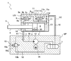
以下、図に示した実施の形態に基づき、本発明を説明する。一実施の形態におけるアクチュエータ1は、基本的には、図1に示すように、シリンダ2と、シリンダ2内に摺動自在に挿入されるピストン3と、シリンダ2内に挿入されてピストン3に連結されるロッド4と、シリンダ2内にピストン3で区画したロッド側室5とピストン側室6とを備えた伸縮体Sと、タンク7と、ロッド側室5とピストン側室6とを連通する第一通路8の途中に設けた第一開閉弁9と、ピストン側室6とタンク7とを連通する第二通路10の途中に設けた第二開閉弁11と、ロッド側室5へ液体を供給するポンプ12と、当該ポンプ12を駆動するモータ15と、ロッド側室5をタンク7へ接続する排出通路18と、排出通路18の途中に設けた弁要素としての可変リリーフ弁19とを備えており、片ロッド型のアクチュエータとして構成されている。
The present invention will be described below based on the embodiments shown in the drawings. As shown in FIG. 1, the actuator 1 in one embodiment basically includes a
そして、このアクチュエータ1にあっては、伸縮体Sと第一開閉弁9と第二開閉弁11とを含んで一体化した伸縮ユニットUSを形成し、ポンプ12とモータ15とを含んで一体化した駆動ユニットUPを形成しており、伸縮ユニットUSと駆動ユニットUPとは別体とされている。
In the actuator 1, an expansion / contraction unit US including the expansion / contraction body S, the first opening /
また、上記ロッド側室5とピストン側室6には作動油等の液体が充填されるとともに、タンク7には、液体のほかに気体が充填されている。なお、タンク7内は、特に、気体を圧縮して充填することによって加圧状態とする必要は無い。
The
そして、基本的には、第一開閉弁9で第一通路8を連通状態とするとともに第二開閉弁11を閉じた状態とし、モータ15でポンプ12を駆動して、シリンダ2内へ液体を供給することで、この伸縮体Sを伸長駆動させることができ、逆に、第二開閉弁11で第二通路10を連通状態とするとともに第一開閉弁9を閉じた状態とし、モータ15でポンプ12を駆動して、シリンダ2内へ液体を供給することで、伸縮体Sを収縮駆動させることができるようになっている。
Basically, the first opening /
以下、各部について詳細に説明する。シリンダ2は筒状であって、その図1中右端は蓋13によって閉塞され、図1中左端には環状のロッドガイド14が取り付けられている。また、上記ロッドガイド14内には、シリンダ2内に移動自在に挿入されるロッド4が摺動自在に挿入されている。このロッド4は、一端をシリンダ2外へ突出させており、シリンダ2内の他端を同じくシリンダ2内に摺動自在に挿入されているピストン3に連結してある。
Hereinafter, each part will be described in detail. The
なお、ロッド4の外周とシリンダ2との間は図示を省略したシール部材によってシールされており、これによりシリンダ2内は密閉状態に維持されている。そして、シリンダ2内にピストン3によって区画されるロッド側室5とピストン側室6には、上述のように液体として作動油が充填されている
The space between the outer periphery of the
また、この伸縮体Sの場合、ロッド4の断面積をピストン3の断面積の二分の一にして、ピストン3のロッド側室5側の受圧面積がピストン側室6側の受圧面積の二分の一となるようになっており、伸長駆動時と収縮駆動時とでロッド側室5の圧力を同じくすると、伸縮の双方で発生される推力が等しくなるようになっており、伸縮体Sの変位量に対する流量も伸縮両側で同じとなる。
Further, in the case of this stretchable body S, the cross-sectional area of the
詳しくは、伸縮体Sを伸長駆動させる場合、ロッド側室5とピストン側室6を連通させた状態となってロッド側室5内とピストン側室6内の圧力が等しくなって、ピストン3におけるロッド側室5側とピストン側室6側の受圧面積差に上記圧力を乗じた推力を発生し、反対に、伸縮体Sを収縮駆動させる場合、ロッド側室5とピストン側室6との連通が断たれてピストン側室6をタンク7に連通させた状態となるので、ロッド側室5内の圧力とピストン3におけるロッド側室5側の受圧面積を乗じた推力を発生することになり、アクチュエータ1の発生推力は伸縮の双方でピストン3の断面積の二分の一にロッド側室5の圧力を乗じた値となるのである。したがって、このアクチュエータ1の推力を制御する場合、伸長駆動、収縮駆動共に、ロッド側室5の圧力を狙った圧力に調節すればよいが、ピストン3のロッド側室5側の受圧面積をピストン側室6側の受圧面積の二分の一に設定しているので、伸縮両側で同じ推力を発生する場合に伸長側と収縮側でロッド側室5の圧力が同じとなるので制御が簡素となり、加えて変位量に対する流量も同じとなるので伸縮両側で応答性が同じとなる利点がある。なお、ピストン3のロッド側室5側の受圧面積をピストン側室6側の受圧面積の二分の一に設定しない場合にあっても、ロッド側室5の圧力で伸縮体Sの伸縮両側の推力の制御をすることができる点は変わらない。
Specifically, when the expansion body S is driven to extend, the
戻って、ロッド4の図1中左端とシリンダ2の右端を閉塞する蓋13には、図示しない取付部を備えており、このアクチュエータ1を車両における車体と車軸との間に介装することができるようになっている。
Returning, the
そして、ロッド側室5とピストン側室6とは、第一通路8によって連通されており、この第一通路8の途中には、第一開閉弁9が設けられている。この第一通路8は、シリンダ2外でロッド側室5とピストン側室6とを連通しているが、ピストン3に設けられてもよい。
The
第一開閉弁9は、この実施の形態の場合、電磁開閉弁とされており、第一通路8を開放してロッド側室5とピストン側室6とを連通する連通ポジション9bと、ロッド側室5とピストン側室6との連通を遮断する遮断ポジション9cとを備えたバルブ9aと、遮断ポジション9cを採るようにバルブ9aを附勢するバネ9dと、通電時にバルブ9aをバネ9dに対向して連通ポジション9bに切換えるソレノイド9eとを備えて構成されている。
In this embodiment, the first on-off
つづいて、ピストン側室6とタンク7とは、第二通路10によって連通されており、この第二通路10の途中には、第二開閉弁11が設けられている。第二開閉弁11は、この実施の形態の場合、電磁開閉弁とされており、第二通路10を開放してピストン側室6とタンク7とを連通する連通ポジション11bと、ピストン側室6とタンク7との連通を遮断する遮断ポジション11cとを備えたバルブ11aと、遮断ポジション11cを採るようにバルブ11aを附勢するバネ11dと、通電時にバルブ11aをバネ11dに対向して連通ポジション11bに切換えるソレノイド11eとを備えて構成されている。
Subsequently, the piston side chamber 6 and the tank 7 are communicated with each other by a
ポンプ12は、この実施の形態の場合、モータ15によって駆動されるようになっており、ポンプ12は、一方向のみに液体を吐出するポンプとされており、その吐出口は供給通路16によってロッド側室5へ連通され、吸込口はタンク7に通じて、モータ15によって駆動されると、タンク7から液体を吸込んでロッド側室5へ液体を供給する。モータ15は、図外のコントローラから電流供給を受けて回転駆動されるようになっている。上述のようにポンプ12は、一方向のみに液体を吐出するのみで回転方向の切換動作がないので、回転切換時に吐出量が変化するといった問題は皆無であり、安価なギアポンプ等を使用することができる。さらに、ポンプ12の回転方向が常に同一方向であるので、ポンプ12を駆動する駆動源であるモータ15にあっても回転方向の切換が不要であるから、回転方向切換に対する高い応答性が要求されず、その分、モータ15も安価なものを使用することができる。
In this embodiment, the
なお、供給通路16の途中には、ロッド側室5からポンプ12への液体の逆流を阻止する逆止弁17を設けてある。
In the middle of the
また、この実施の形態の場合、ロッド側室5とタンク7とが排出通路18を通じて接続されており、この排出通路18の途中には、弁要素としての可変リリーフ弁19が設けられている。
In the case of this embodiment, the
可変リリーフ弁19は、排出通路18の途中に設けた弁体19aと、排出通路18を遮断するように弁体19aを附勢するバネ19bと、通電時にバネ19bに対抗する推力を発生する比例ソレノイド19cとを備えて構成され、比例ソレノイド19cに流れる電流量を調節することで開弁圧を調節することができるようになっている。
The
この可変リリーフ弁19は、弁体19aに作用させる排出通路18の上流となるロッド側室5の圧力がリリーフ圧を超えると、当該排出通路18を開放させる方向に弁体19aを推す上記圧力に起因する推力と比例ソレノイド19cによる推力との合力が、排出通路18を遮断させる方向へ弁体19aを附勢するバネ19bの附勢力に打ち勝つようになって、弁体19aを後退させて排出通路18を開放するようになっている。
This
また、この可変リリーフ弁19にあっては、比例ソレノイド19cに供給する電流量を増大させると、比例ソレノイド19cが発生する推力を増大させることができるようになっており、比例ソレノイド19cに供給する電流量を最大とすると開弁圧が最小となり、反対に、比例ソレノイド19cに全く電流を供給しないと開弁圧が最大となる。
In the
そして、可変リリーフ弁19は、第一開閉弁9および第二開閉弁11の開閉状態に関わらず、伸縮体Sに伸縮方向の過大な入力があって、ロッド側室5の圧力が開弁圧を超える状態となると、排出通路18を開放してロッド側室5をタンク7へ連通し、ロッド側室5内の圧力をタンク7へ逃がして、アクチュエータ1のシステム全体を保護するようになっている。
In the
この実施の形態のアクチュエータ1では可変リリーフ弁19を備えているので、この可変リリーフ弁19の開弁圧を調節することでロッド側室5の圧力をコントロールしてアクチュエータ1の推力を制御することができる。つまり、可変リリーフ弁19によってロッド側室5の圧力制御し、第一開閉弁9および第二開閉弁11で推力の方向を決定するように制御する。
Since the actuator 1 of this embodiment includes the
たとえば、伸縮体Sを伸長しつつ伸長方向の推力を出力させる場合、第一開閉弁9を連通ポジション9bとし第二開閉弁11を遮断ポジション11cとし、モータ15を駆動してポンプ12からシリンダ2内へ液体を供給する。この動作とともに、比例ソレノイド19cの電流量を調節して可変リリーフ弁19の開弁圧とピストン3におけるピストン側室6側とロッド側室5側の受圧面積差とを乗じた値が上記所望の推力と同じとなるように上記開弁圧を調節する。
For example, when a thrust in the extension direction is output while extending the telescopic body S, the first opening /
すなわち、ピストン側室6と同圧となるロッド側室5の圧力が可変リリーフ弁19の開弁圧を超えると可変リリーフ弁19が開いてピストン側室6およびロッド側室5の圧力がタンク7へ逃げ、反対にロッド側室5の圧力が可変リリーフ弁19の開弁圧を下回ると可変リリーフ弁19が閉じてピストン側室6およびロッド側室5の圧力がポンプ12からの液体供給によって上昇することになるので、結果、ピストン側室6およびロッド側室5の圧力は、可変リリーフ弁19の開弁圧に制御され、これによって、シリンダ装置1の伸長方向への推力を所望した通りに得ることができる。よって、この制御を行うには、可変リリーフ弁19の比例ソレノイド19cへの電流量と開弁圧の関係を把握しておけばよく、オープンループ制御を行うことができる。なお、比例ソレノイド19cへの通電量をセンシングしておき電流ループを用いてフィードバック制御を行ってもよく、さらに、ロッド側室5の圧力をセンシングしてフィードバック制御することも可能である。
That is, when the pressure in the
また、伸縮体Sが外力を受けて収縮しつつもこれに抵抗する伸長方向の所望の推力を得たい場合、伸長しつつ伸長方向の推力を得るのと同じように、第一開閉弁9を連通ポジション9bとし第二開閉弁11を遮断ポジション11cとし、モータ15を駆動してポンプ12からシリンダ2内へ液体を供給する状態で可変リリーフ弁19の開弁圧を調節して、所望の推力を得ることができる。なお、この場合には、伸縮体Sは外力以上の推力を発揮しない状態であるので、伸縮体Sをダンパとして機能させれば足りることから、ポンプ12からの液体供給を断って、第一開閉弁9を連通ポジション9bとし第二開閉弁11を遮断ポジション11cとし、可変リリーフ弁19の開弁圧を制御することによっても所望の推力を得ることができる。
Further, when it is desired to obtain a desired thrust in the extending direction that resists the expansion and contraction while receiving contraction by the external force, the first opening /
これに対して、伸縮体Sを収縮しつつ収縮方向の推力を得たい場合、第一開閉弁9を遮断ポジション9cとし第二開閉弁11を連通ポジション11bとし、モータ15を駆動してポンプ12からシリンダ2内へ液体を供給する。この動作とともに、比例ソレノイド19cの電流量を調節して可変リリーフ弁19の開弁圧とピストン3におけるロッド側室5側の受圧面積とを乗じた値が上記所望の推力と同じとなるように上記開弁圧を調節する。
On the other hand, when it is desired to obtain the thrust in the contraction direction while contracting the expansion / contraction body S, the first on-off
すなわち、ロッド側室5の圧力が可変リリーフ弁19の開弁圧を超えると可変リリーフ弁19が開いて圧力がタンク7へ逃げ、反対にロッド側室5の圧力が可変リリーフ弁19の開弁圧を下回ると可変リリーフ弁19が閉じてロッド側室5の圧力がポンプ12からの液体供給によって上昇することになるので、結果、ロッド側室5の圧力は、可変リリーフ弁19の開弁圧に制御され、これによって、伸縮体Sの収縮方向の推力を所望した通りに得ることができる。なお、ピストン側室6は第二開閉弁11の連通ポジション11bによってタンク7へ連通されるので、伸縮体Sの収縮動作を妨げることが無い。
That is, when the pressure in the
また、伸縮体Sが外力を受けて伸長しつつもこれに抵抗する収縮方向の所望の推力を得たい場合、収縮しつつ収縮方向の推力を得るのと同じように、第一開閉弁9を遮断ポジション9cとし第二開閉弁11を連通ポジション11bとし、モータ15を駆動してポンプ12からシリンダ2内へ液体を供給する状態で可変リリーフ弁19の開弁圧を調節して、所望の推力を得ることができる。なお、この場合には、伸縮体Sは外力以上の推力を発揮しない状態であるので、伸縮体Sをダンパとして機能させれば足りることから、ポンプ12からの液体供給を断って、第一開閉弁9を遮断ポジション9cとし第二開閉弁11を連通ポジション11bとし、可変リリーフ弁19の開弁圧を制御することによっても所望の推力を得ることができる。
In addition, when it is desired to obtain a desired thrust in the contraction direction that resists the expansion and contraction of the expansion body S under external force, the first on-off
このようにアクチュエータ1にあっては、ロッド側室5をタンク7に連通する排出通路18の途中に可変リリーフ弁19を設けているので、可変リリーフ弁19の開弁圧の制御によって推力を制御することができる。なお、弁要素を可変リリーフ弁以外の弁を利用することもできる。たとえば、弁要素を所定の圧力流量特性を備えたパッシブ弁とする場合、パッシブ弁を通過する液体の流量によって上流側のロッド側室5内の圧力が決まる関係になるので、伸縮体Sに出力させたい推力の方向によって、上記したところと同様に第一開閉弁9と第二開閉弁11を切換制御しつつ、ポンプ12の吐出流量を調節することで、パッシブ弁を通過する液体の流量を調節することができ、アクチュエータ1の推力を狙い通りに制御することができる。また、弁要素を単にリリーフ弁とする場合、伸縮体Sに伸長方向の推力を出力させるには、第一開閉弁9を開状態に維持しつつ、第二開閉弁11を開閉することでロッド側室5内の圧力を調節し、狙い通りの伸長方向の推力を得ることができ、反対に、伸縮体Sに収縮方向の推力を出力させるには、第二開閉弁10を開状態に維持しつつ、第一開閉弁9を開閉することでロッド側室5内の圧力を調節し、狙い通りの収縮方向の推力を得ることができる。上記したところから、弁要素には種々の弁を利用することができ、採用した弁に応じて、アクチュエータ1の推力を制御することが可能である。
In this way, in the actuator 1, the
また、このアクチュエータ1は、整流通路20と吸込通路21を設けているので、外力によって強制的に伸縮させられる場合には、第一開閉弁9と第二開閉弁11を共に遮断ポジション9c,11cとしてポンプ12の駆動を停止させると、伸縮によってシリンダ2内から液体が押し出され弁要素としての可変リリーフ弁19を介してタンク7へ液体が排出され、シリンダ2内で液体が不足する場合には液体がタンク7から吸込通路21を介してシリンダ2内に供給されることになり、可変リリーフ弁19の圧力損失に見合った減衰力を発揮するパッシブなダンパとしても機能することができる。つまり、第一開閉弁9と第二開閉弁11が遮断ポジション9c,11cを採り、ポンプ12が停止状態となるフェール時にあっても、アクチュエータ1はパッシブなダンパとして機能することができ、伸縮不能となってしまうことがない。
In addition, since the actuator 1 is provided with the rectifying
以上のようにアクチュエータ1の各部が構成されるが、このアクチュエータ1にあっては、伸縮体S、第一開閉弁9および第二開閉弁10を含んで、これらを一体化して伸縮ユニットUSとし、ポンプ12、モータ15、可変リリーフ弁19、逆止弁17およびタンク7を含んで、これらを一体化して駆動ユニットUPとしてあって、伸縮ユニットUSと駆動ユニットUPとは別体とされている。なお、伸縮ユニットUSと駆動ユニットUPとは、図1および2に示すように、供給通路16の一部を形成する配管H1と、第二通路10の一部を形成する配管H2で接続されており、ポンプ12からシリンダ2への液体の供給と、シリンダ2からタンク7への液体の排出が可能となっている。
As described above, each part of the actuator 1 is configured. The actuator 1 includes the telescopic body S, the first on-off
また、この場合、駆動ユニットUPからタンク7を廃して、伸縮ユニットUS側にタンク7を設けるようにしてもよいし、駆動ユニットUPから可変リリーフ弁19を廃して、伸縮ユニットUS側に可変リリーフ弁19を設けるようにしてもよい。
Further, in this case, the tank 7 may be eliminated from the drive unit UP and the tank 7 may be provided on the telescopic unit US side, or the
そして、このアクチュエータ1を鉄道車両に搭載する場合、図2に示すように、伸縮ユニットUSの伸縮体Sの一端を、台車Wの図外の車輪を保持する一対の側梁30,31を連結する一対の横梁32,33に架け渡されたアクチュエータ保持部34に連結し、伸縮ユニットUSの伸縮体Sの他端を車体Bの下端に固定された中心ピン35に連結することで、伸縮ユニットUSを台車Wと車体Bとの間に介装するとともに、駆動ユニットUPは、中心ピン35の伸縮ユニットUSとは反対側であって横梁32,33間に架け渡された設置部36に固定される。なお、駆動ユニットUPは、伸縮体Sに対して中心ピン35を挟んで反対側に配置されるのであれば、車体Bの下端に固定するようにしてもよい。
When the actuator 1 is mounted on a railway vehicle, as shown in FIG. 2, one end of the expansion body S of the expansion / contraction unit US is connected to a pair of side beams 30 and 31 that hold wheels outside the drawing of the carriage W. The telescopic unit is connected to the
よって、駆動ユニットUPは、伸縮体Sの中心ピン35を挟んで反対側に配置されていて、駆動ユニットUPと伸縮ユニットUSが並列することがないので、在来線のように、台車Wにおける車軸間距離が比較的狭い鉄道車両にも無理なく搭載することが可能である。以上より、本発明のアクチュエータ1によれば、駆動ユニットUPと伸縮ユニットUSとが別体であって分離されているので、設置箇所へ駆動ユニットUPと伸縮ユニットUSを別々の箇所に取り付けることができるので、狭小な設置箇所へも無理なく搭載することができ、搭載性に優れる。
Therefore, the drive unit UP is disposed on the opposite side across the
また、一つの駆動ユニットUPで複数の伸縮ユニットUSを駆動することも可能である。この場合、たとえば、図3に示すように、一方の伸縮ユニットUSの伸縮体Sを、台車Wの二つあるアクチュエータ保持部34の一方に連結し、一方の伸縮ユニットUSの伸縮体Sの他端を中心ピン35の一方側に連結するようにし、他方の伸縮ユニットUSの伸縮体Sを、台車Wの二つあるアクチュエータ保持部34の他方に連結し、他方の伸縮ユニットUSの伸縮体Sの他端を中心ピン35の他方側に連結するようにし、駆動ユニットUPは、伸縮ユニットUSの邪魔にならない位置に取り付ければよく、たとえば、中心ピン35の内部が空洞であるため、当該中心ピン35内に収容するようにすることもできる。このように二つ以上の複数の伸縮ユニットUSへ一つの駆動ユニットUPから液体を供給して、これら伸縮ユニットUSを一つの駆動ユニットUPで駆動するようにしてもよい。また、この場合、駆動ユニットUP側に弁要素である可変リリーフ弁19を設けておくことで、伸縮ユニットUSの双方に弁要素である可変リリーフ弁19を設けなくても済み、アクチュエータ1の全体がより小型化されるので搭載性がより一層向上する。なお、中心ピン35内に駆動ユニットUPを収容する場合にあっても、一つの伸縮ユニットUSのみに液体を供給するようにしてもよい。
It is also possible to drive a plurality of expansion / contraction units US with one drive unit UP. In this case, for example, as shown in FIG. 3, the expansion body S of one expansion unit US is connected to one of the two
以上で、本発明の実施の形態についての説明を終えるが、本発明の範囲は図示されまたは説明された詳細そのものには限定されないことは勿論である。 This is the end of the description of the embodiment of the present invention, but the scope of the present invention is of course not limited to the details shown or described.
1 アクチュエータ
2 シリンダ
3 ピストン
4 ロッド
5 ロッド側室
6 ピストン側室
7 タンク
8 第一通路
9 第一開閉弁
10 第二通路
11 第二開閉弁
12 ポンプ
15 モータ
16 供給通路
17 逆止弁
18 排出通路
19 弁要素としての可変リリーフ弁
20 整流通路
21 吸込通路
35 中心ピン
B 車体
UP 駆動ユニット
US 伸縮ユニット
S 伸縮体
W 台車
DESCRIPTION OF SYMBOLS 1
Claims (6)
2. A suction passage that allows only a liquid flow from the tank to the piston-side chamber, and a rectification passage that allows only a liquid flow from the piston-side chamber to the rod-side chamber. The actuator according to any one of 5.
Priority Applications (8)
| Application Number | Priority Date | Filing Date | Title |
|---|---|---|---|
| JP2012179156A JP5543996B2 (en) | 2012-08-13 | 2012-08-13 | Actuator |
| PCT/JP2013/070984 WO2014027576A1 (en) | 2012-08-13 | 2013-08-02 | Actuator |
| CN201380030364.8A CN104350289B (en) | 2012-08-13 | 2013-08-02 | Actuator |
| US14/407,473 US9702383B2 (en) | 2012-08-13 | 2013-08-02 | Actuator |
| CA2878141A CA2878141C (en) | 2012-08-13 | 2013-08-02 | Actuator |
| EP13879320.3A EP2848819A4 (en) | 2012-08-13 | 2013-08-02 | Actuator |
| KR1020147033495A KR101675660B1 (en) | 2012-08-13 | 2013-08-02 | Actuator |
| IN545KON2015 IN2015KN00545A (en) | 2012-08-13 | 2015-03-03 |
Applications Claiming Priority (1)
| Application Number | Priority Date | Filing Date | Title |
|---|---|---|---|
| JP2012179156A JP5543996B2 (en) | 2012-08-13 | 2012-08-13 | Actuator |
Publications (2)
| Publication Number | Publication Date |
|---|---|
| JP2014037850A JP2014037850A (en) | 2014-02-27 |
| JP5543996B2 true JP5543996B2 (en) | 2014-07-09 |
Family
ID=50286135
Family Applications (1)
| Application Number | Title | Priority Date | Filing Date |
|---|---|---|---|
| JP2012179156A Active JP5543996B2 (en) | 2012-08-13 | 2012-08-13 | Actuator |
Country Status (8)
| Country | Link |
|---|---|
| US (1) | US9702383B2 (en) |
| EP (1) | EP2848819A4 (en) |
| JP (1) | JP5543996B2 (en) |
| KR (1) | KR101675660B1 (en) |
| CN (1) | CN104350289B (en) |
| CA (1) | CA2878141C (en) |
| IN (1) | IN2015KN00545A (en) |
| WO (1) | WO2014027576A1 (en) |
Families Citing this family (10)
| Publication number | Priority date | Publication date | Assignee | Title |
|---|---|---|---|---|
| JP6397220B2 (en) * | 2014-05-12 | 2018-09-26 | Kyb株式会社 | Cylinder device |
| DE102014013018A1 (en) * | 2014-09-02 | 2016-03-03 | Hydac System Gmbh | Hydraulic system |
| DE102015113176B4 (en) | 2015-08-10 | 2021-12-30 | Grammer Aktiengesellschaft | Horizontal vibration device for a vehicle seat |
| JP6523916B2 (en) * | 2015-10-27 | 2019-06-05 | Kyb株式会社 | Hydraulic equipment |
| AT16161U1 (en) * | 2016-07-21 | 2019-03-15 | Pimatic Oy | oscillation |
| JP6817786B2 (en) * | 2016-11-04 | 2021-01-20 | Kyb株式会社 | Cylinder device |
| US20210270295A1 (en) * | 2017-04-13 | 2021-09-02 | Advanced Concepts in Manufacturing LLC | Restraint Systems and Restraint System Methods |
| JP2019091868A (en) * | 2017-11-17 | 2019-06-13 | Kyb株式会社 | Control device and damping device for railway vehicle |
| IT201800004110A1 (en) * | 2018-03-30 | 2019-09-30 | Camozzi Automation S P A | PRESSURE REGULATOR |
| CN114278642A (en) * | 2021-12-24 | 2022-04-05 | 扬州大山液压气动制造有限公司 | Marine lifting normally closed cylinder |
Family Cites Families (9)
| Publication number | Priority date | Publication date | Assignee | Title |
|---|---|---|---|---|
| JPS5445465A (en) * | 1977-09-16 | 1979-04-10 | Ichikoh Ind Ltd | Hydraulic driver |
| JP2002245904A (en) * | 2001-02-22 | 2002-08-30 | Hitachi Ltd | Hydraulic drive device of breaker |
| JP2003139108A (en) * | 2001-11-07 | 2003-05-14 | Shimadzu Corp | Hydraulic actuator |
| JP3926253B2 (en) * | 2002-11-21 | 2007-06-06 | ジャパン・ハムワージ株式会社 | Valve block structure of rotary vane type steering machine |
| JP2005007944A (en) * | 2003-06-17 | 2005-01-13 | Hitachi Ltd | Vibration control device of rolling stock |
| JP2006137294A (en) * | 2004-11-12 | 2006-06-01 | Hitachi Ltd | Vibration control device for railway vehicle |
| DE102008027474B4 (en) * | 2008-06-09 | 2022-12-15 | Liebherr-Aerospace Lindenberg Gmbh | Actuator and bogie control |
| JP5364323B2 (en) | 2008-09-12 | 2013-12-11 | カヤバ工業株式会社 | Cylinder device |
| JP5486367B2 (en) * | 2010-03-24 | 2014-05-07 | カヤバ工業株式会社 | Actuator unit |
-
2012
- 2012-08-13 JP JP2012179156A patent/JP5543996B2/en active Active
-
2013
- 2013-08-02 US US14/407,473 patent/US9702383B2/en not_active Expired - Fee Related
- 2013-08-02 KR KR1020147033495A patent/KR101675660B1/en active IP Right Grant
- 2013-08-02 CN CN201380030364.8A patent/CN104350289B/en not_active Expired - Fee Related
- 2013-08-02 WO PCT/JP2013/070984 patent/WO2014027576A1/en active Application Filing
- 2013-08-02 CA CA2878141A patent/CA2878141C/en not_active Expired - Fee Related
- 2013-08-02 EP EP13879320.3A patent/EP2848819A4/en not_active Withdrawn
-
2015
- 2015-03-03 IN IN545KON2015 patent/IN2015KN00545A/en unknown
Also Published As
| Publication number | Publication date |
|---|---|
| KR101675660B1 (en) | 2016-11-11 |
| CN104350289B (en) | 2017-05-03 |
| IN2015KN00545A (en) | 2015-07-17 |
| WO2014027576A1 (en) | 2014-02-20 |
| CN104350289A (en) | 2015-02-11 |
| EP2848819A4 (en) | 2016-01-20 |
| CA2878141A1 (en) | 2014-02-20 |
| US20150184683A1 (en) | 2015-07-02 |
| EP2848819A1 (en) | 2015-03-18 |
| JP2014037850A (en) | 2014-02-27 |
| CA2878141C (en) | 2016-12-06 |
| KR20150005687A (en) | 2015-01-14 |
| US9702383B2 (en) | 2017-07-11 |
Similar Documents
| Publication | Publication Date | Title |
|---|---|---|
| JP5543996B2 (en) | Actuator | |
| JP5517368B2 (en) | Actuator | |
| JP5364323B2 (en) | Cylinder device | |
| US8776961B2 (en) | Shock absorber and suspension apparatus | |
| JP6368204B2 (en) | Railway vibration control device | |
| JP6363934B2 (en) | Cylinder device | |
| JP5552174B1 (en) | Actuator | |
| JP6663197B2 (en) | Suspension device | |
| JP5427082B2 (en) | Vibration control device for railway vehicles | |
| JP5572236B1 (en) | Actuator | |
| JP6663196B2 (en) | Suspension device | |
| JP6243205B2 (en) | Suspension device | |
| JP6654943B2 (en) | Railcar damper | |
| JP2019124312A (en) | Hydraulic shock absorber | |
| JP2017196919A (en) | Suspension device | |
| JP2023119628A (en) | Cylinder device | |
| JP2019183978A (en) | Damper for railroad car |
Legal Events
| Date | Code | Title | Description |
|---|---|---|---|
| A975 | Report on accelerated examination |
Free format text: JAPANESE INTERMEDIATE CODE: A971005 Effective date: 20140115 |
|
| A131 | Notification of reasons for refusal |
Free format text: JAPANESE INTERMEDIATE CODE: A131 Effective date: 20140121 |
|
| A521 | Request for written amendment filed |
Free format text: JAPANESE INTERMEDIATE CODE: A523 Effective date: 20140314 |
|
| TRDD | Decision of grant or rejection written | ||
| A01 | Written decision to grant a patent or to grant a registration (utility model) |
Free format text: JAPANESE INTERMEDIATE CODE: A01 Effective date: 20140423 |
|
| A61 | First payment of annual fees (during grant procedure) |
Free format text: JAPANESE INTERMEDIATE CODE: A61 Effective date: 20140509 |
|
| R151 | Written notification of patent or utility model registration |
Ref document number: 5543996 Country of ref document: JP Free format text: JAPANESE INTERMEDIATE CODE: R151 |
|
| S533 | Written request for registration of change of name |
Free format text: JAPANESE INTERMEDIATE CODE: R313533 |
|
| R350 | Written notification of registration of transfer |
Free format text: JAPANESE INTERMEDIATE CODE: R350 |
|
| S533 | Written request for registration of change of name |
Free format text: JAPANESE INTERMEDIATE CODE: R313533 |
|
| R350 | Written notification of registration of transfer |
Free format text: JAPANESE INTERMEDIATE CODE: R350 |