JP5538909B2 - Detection apparatus and method - Google Patents
Detection apparatus and method Download PDFInfo
- Publication number
- JP5538909B2 JP5538909B2 JP2010000793A JP2010000793A JP5538909B2 JP 5538909 B2 JP5538909 B2 JP 5538909B2 JP 2010000793 A JP2010000793 A JP 2010000793A JP 2010000793 A JP2010000793 A JP 2010000793A JP 5538909 B2 JP5538909 B2 JP 5538909B2
- Authority
- JP
- Japan
- Prior art keywords
- region
- edge
- area
- head
- color
- Prior art date
- Legal status (The legal status is an assumption and is not a legal conclusion. Google has not performed a legal analysis and makes no representation as to the accuracy of the status listed.)
- Expired - Fee Related
Links
Images


Classifications
-
- G—PHYSICS
- G06—COMPUTING; CALCULATING OR COUNTING
- G06V—IMAGE OR VIDEO RECOGNITION OR UNDERSTANDING
- G06V40/00—Recognition of biometric, human-related or animal-related patterns in image or video data
- G06V40/10—Human or animal bodies, e.g. vehicle occupants or pedestrians; Body parts, e.g. hands
- G06V40/16—Human faces, e.g. facial parts, sketches or expressions
- G06V40/161—Detection; Localisation; Normalisation
- G06V40/164—Detection; Localisation; Normalisation using holistic features
Description
本発明は、カメラなどの撮影装置により撮影された映像から人物の頭部領域を検出する装置に関する。 The present invention relates to an apparatus for detecting a head region of a person from an image captured by an imaging apparatus such as a camera.
近年、カメラなどの撮影装置から撮影された映像に指定された人物の位置を特定し追尾することにより、カメラのフォーカスや露出、あるいはカメラのパン、チルト、ズームなどの姿勢を自動的に制御する機能が注目されている。 In recent years, the focus and exposure of the camera, or the posture of the camera such as pan, tilt, zoom, etc. are automatically controlled by identifying and tracking the position of the person specified in the video taken from the camera or other imaging device. The function is drawing attention.
これまでは人物の位置を特定するために、人物の顔パターンを検出しその動きを追尾することが一般的であった。このような画像中から顔を検出する技術としては、非特許文献1に各種方式が挙げられている。特に、検出の実行速度とその検出率の高さから、非特許文献2に記載のAdaBoostベースの手法は、顔検出研究において広く使用されてきた。しかし、人物の位置を特定するのに、人物の顔パターンを検出し追尾するだけでは十分ではない。なぜなら、人物の顔が横向きになったり後ろ向きになると顔パターンが検出できない場合があるからである。
In the past, in order to identify the position of a person, it has been common to detect the face pattern of the person and track its movement. As a technique for detecting a face from such an image, Non-Patent
したがって、顔を検出する変わりに頭部領域を検出し追尾することは、顔パターン検出の欠点を補う有力な手段である。頭部領域を検出するには、非特許文献3に記載のハフ変換を用いた曲線の検出や、非特許文献4に記載の楕円検出などを用いることができる。
Therefore, detecting and tracking the head region instead of detecting the face is an effective means to compensate for the drawbacks of face pattern detection. In order to detect the head region, detection of a curve using Hough transform described in Non-Patent
しかしながら、ハフ変換や非特許文献4に記載の手法を用いて頭部楕円を検出しようとしても、顔色と髪色間に頭部と背景間と同程度の強度を有するエッジが存在することが多い。このため顔色と髪色間のエッジが頭部エッジとして誤って見なされることが多くなる。この誤検出が続くと、人物の追尾に不安定を生じ、例えば、人物が後ろを向いてしまうと、追跡していた顔色と髪色間のエッジが消滅してしまい、人物をロストしてしまうという課題があった。 However, even when trying to detect a head ellipse using the Hough transform or the technique described in Non-Patent Document 4, there is often an edge between the face color and the hair color that has the same strength as between the head and the background. . For this reason, the edge between the face color and the hair color is often mistakenly regarded as the head edge. If this false detection continues, tracking of the person will become unstable. For example, if the person turns backward, the edge between the face color and hair color that was tracked disappears, and the person is lost. There was a problem.
本発明はこのような課題に鑑みて成されたものであり、頭部内のエッジを頭部の境界として誤検出することを防ぎ、頭部領域を精度よく検出することを目的とする。 The present invention has been made in view of such a problem, and an object of the present invention is to prevent erroneous detection of an edge in the head as a head boundary and to detect a head region with high accuracy.
本発明の目的を達成するために、本発明の画像処理装置は以下のように構成される。すなわち、画像から人物の顔領域を検出する顔検出手段と、前記検出された人物の顔領域に基づいて頭部検出領域を設定する頭部検出領域設定手段と、前記設定された頭部検出領域のエッジを検出してエッジ画像を生成するエッジ検出手段と、前記顔領域の色に基づいて前記頭部検出領域から肌色領域を検出する肌色領域検出手段と、検出された前記肌色領域と所定の位置関係を有する領域の色分布に基づいて、前記頭部検出領域から髪色領域を検出する髪色領域検出手段と、前記エッジ画像において、前記肌色領域と前記髪色領域との間のエッジ画素を削除するエッジ削除手段と、前記エッジ削除手段によりエッジ画素が削除されたエッジ画像から頭部領域に対応した候補楕円を検出する楕円検出手段とを備えることを特徴とする。 In order to achieve the object of the present invention, the image processing apparatus of the present invention is configured as follows. That is, face detection means for detecting a human face area from an image, head detection area setting means for setting a head detection area based on the detected human face area, and the set head detection area Edge detection means for detecting an edge of the face area to generate an edge image, skin color area detection means for detecting a skin color area from the head detection area based on the color of the face area, and the detected skin color area and a predetermined area A hair color region detecting means for detecting a hair color region from the head detection region based on a color distribution of a region having a positional relationship; and an edge pixel between the skin color region and the hair color region in the edge image. And an ellipse detection means for detecting a candidate ellipse corresponding to the head region from the edge image from which the edge pixel has been deleted by the edge deletion means.
本発明の構成により、顔色領域と髪色領域を含む頭部領域について、頭部内のエッジに対する誤検出を防止し、頭部領域を精度よく検出することができる。 With the configuration of the present invention, it is possible to prevent the head region including the face color region and the hair color region from being erroneously detected with respect to the edge in the head and to detect the head region with high accuracy.
<実施形態1>
(構成)
以下に、図面を参照しながら、本発明の実施形態1について説明していく。
<
(Constitution)
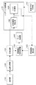
図1は実施形態1における人物の頭部領域を検出する装置の構成例を示すブロック図である。実施形態1において、頭部は楕円として検出するので、厳密に言うと頭部領域はその楕円領域であるが、処理を簡単にするために、頭部領域はその楕円の外接矩形とすることもある。以下の説明では、頭部楕円と頭部楕円の外接矩形は区別せず頭部領域とする。 FIG. 1 is a block diagram illustrating a configuration example of an apparatus for detecting a head region of a person in the first embodiment. In the first embodiment, since the head is detected as an ellipse, strictly speaking, the head region is the ellipse region. However, in order to simplify the processing, the head region may be a circumscribed rectangle of the ellipse. is there. In the following description, the head ellipse and the circumscribed rectangle of the head ellipse are not distinguished and are referred to as a head region.
まず、撮影部101により人物を含む画像が撮影される。画像取得部102は、撮影部101より撮影された画像をフレーム画像として取得する。フレーム画像は、一般に撮影部101から同軸ケーブルを介して、コンピュータのビデオインターフェースにより取得される。顔検出部103は、画像取得部102から送られる一連のフレーム画像の現在フレーム画像を解析し、顔領域を検出する。頭部検出領域設定部104は、顔検出部103で求められた顔領域、または頭部領域検出部109から求めた前フレームの頭部領域に基づいて、現在フレームに対して人物の頭部検出範囲を設定する。
First, an image including a person is photographed by the photographing
エッジ検出部105は、前記頭部検出領域設定部104で設定された頭部検出領域のエッジ画像を生成する。ノイズエッジ削除部120は、肌色領域検出部106と、肌色とエッジ削除部108から構成される。肌色領域検出部106は、顔検出部103で求められた顔領域を利用して、肌色分布を抽出し、前記設定された頭部検出領域から肌色領域を検出する。エッジ削除部108は、前記肌色領域検出部106で求めた肌色領域を拡張して、拡張した領域内のエッジ画素を削除する。楕円検出手段である頭部領域検出部109は、前記肌色とエッジ削除部108から出力した、ノイズエッジ画素が削除されたエッジ画像を利用して、頭部楕円を検出する。
The
ノイズエッジ削除部120を作動させるか否かの指示をあらかじめ外部入力により行えるようにし、作動フラグ設定部110は、例えばマニュアルによる外部からの指示に基づき作動フラグを設定する。すなわち、エッジ検出部105で検出した頭部検出領域のエッジ画像を直接頭部領域検出部109に入力し頭部楕円を検出する場合は、作動フラグを「L」とする。作動フラグを「H」に設定することで、エッジ検出部105で検出した頭部検出領域のエッジ画像から肌色領域と髪色領域間エッジを削除したエッジ画像を、頭部領域検出部109に入力して頭部楕円が検出される。
An instruction as to whether or not to operate the noise
(動作フロー)
図2は、実施形態1の頭部楕円の検出に関するフローチャートである。次に、このフローチャートを用いて処理の流れを説明する。ステップS101において、ノイズエッジ削除部120の動作・非動作を決定する作動フラグ設定部110の出力を設定する。作動フラグは、外部入力(不図示)により設定される。作動フラグが「H」の場合、ノイズエッジ削除部120の全体を動作させ、作動フラグが「L」の場合、ノイズエッジ削除部120を非動作にし、顔検出部103の出力は直接、頭部領域検出部109へ送られる。
(Operation flow)
FIG. 2 is a flowchart regarding detection of a head ellipse according to the first embodiment. Next, the flow of processing will be described using this flowchart. In step S101, the output of the operation
つまり、作動フラグが「H」の場合には、肌色と髪色領域間エッジを削除し頭部楕円が検出される。作動フラグが「L」の場合、エッジ検出部105で検出した頭部検出領域のエッジ画像を利用して頭部楕円が検出される。ステップS102において、画像取得部102は、コンピュータのビデオインターフェースにより、同軸ケーブルを介して、撮影部101へ入力された映像をフレーム画像として取得する。
That is, when the operation flag is “H”, the edge between the skin color and the hair color region is deleted and the head ellipse is detected. When the operation flag is “L”, the head ellipse is detected using the edge image of the head detection area detected by the
ステップS103において、顔検出部103は、ステップS102で取得したフレーム画像に対して顔検出を行い、全ての顔領域を検出する。人物の頭部領域検出手段に比べ、顔検出手段は顔という特定の領域に着目するので、小領域で各種照明条件に安定して被写体を検出できる。
ステップS104において、肌色領域検出部106は、ステップS103で検出した顔領域のRGB画像Iを、式(1)を用いてYUV画像に変換する。

In step S104, the skin color
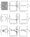
ステップS103で検出した顔領域には、目、鼻の穴、唇などの領域が含まれており、これらの領域を除去して肌色の分布を作成する必要がある。実施形態1においては、肌色の分布はYUVのそれぞれの成分について求める。図3の(a)は、撮像された人物のフレーム像を示す。図3の(b)は、検出された顔の部分のRGB画像を示す。また、図3の(c)は、顔領域の肌色の画素の分布を示す。 The face area detected in step S103 includes areas such as eyes, nostrils, and lips, and it is necessary to create a skin color distribution by removing these areas. In the first embodiment, the skin color distribution is obtained for each component of YUV. FIG. 3A shows a frame image of a captured person. FIG. 3B shows an RGB image of the detected face portion. FIG. 3C shows the distribution of skin color pixels in the face area.
図3の(d)〜(f)に示すように、それぞれの顔領域のY、U、Vに関する色の分布が、最大値PYmax、 PUmax、PVmaxの位置から左右へ小さくなる。そして、図3の(g)〜(h)に示すように、顔領域色分布が、α・PYmax、 α・PUmax、 α・PVmaxの各値に対して、初めて小さくなる位置を求める。この求められた左右の位置に挟まれた左右範囲内の顔領域色分布を肌色分布とする。ここでのα値は、例えばα=0.1としている。 As shown in (d) to (f) of FIG. 3, the distribution of colors related to Y, U, and V in the respective face regions decreases from the position of the maximum values P Ymax , P Umax , and P Vmax to the left and right. Then, as shown in (g) to (h) of FIG. 3, a position where the face area color distribution becomes small for the first time with respect to each of α · P Ymax , α · P Umax , α · P Vmax is obtained. . The face area color distribution within the left and right range sandwiched between the obtained left and right positions is defined as the skin color distribution. The α value here is, for example, α = 0.1.
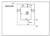
図4は、直前フレームが存在しない場合に行われる、顔領域による頭部検出領域の設定例を示す図である。ステップS105において、頭部検出領域設定部104は、ステップS103で検出した顔領域が始めて検出される場合、図4に示すように、検出した顔領域の横幅wfと縦高hfに基づいて、頭部検出領域を設定する。
FIG. 4 is a diagram illustrating a setting example of a head detection area based on a face area, which is performed when there is no previous frame. In step S105, when the face area detected in step S103 is detected for the first time, the head detection
顔領域の左上端である点Pの座標を(xf1,yf1)とし、右下端点である点Qの座標を(xf3,yf3)とする。このとき、頭部検出領域の左上端点である点Rの座標は(xf1−c1・wf, yf1―c3・hf)、右下端点である点Sの座標は(xf3+c2・wf, yf1+c4・hf)で表される。ここで、c1、c2、c3およびc4は変数であり、その値は例えばc1=c2=c3=c4=1.0を用いる。 The coordinates of the point P that is the upper left corner of the face area are (xf1, yf1), and the coordinates of the point Q that is the lower right corner are (xf3, yf3). At this time, the coordinates of the point R that is the upper left end point of the head detection area are (xf1−c1 · wf, yf1−c3 · hf), and the coordinates of the point S that is the lower right end point are (xf3 + c2 · wf, yf1 +). c4 · hf). Here, c1, c2, c3 and c4 are variables, and for example, c1 = c2 = c3 = c4 = 1.0 is used.
図5は、前フレームの頭部領域が存在する場合の頭部検出領域の設定例を示す図である。ステップS105において、頭部検出領域設定部104は、ステップS103で検出した顔領域が始めてではない場合、図5に示すように、後述のステップS113で検出した前フレームの頭部領域に基づいて、被写体の頭部領域のまわりに頭部検出領域を設定する。本実施形態において、前フレームの頭部領域の左上端点である点pの座標を(xd1,yd1)とし、右下端点である点qの座標を(xd3,yd3)とし、横幅はwd、縦高はhdとする。このとき、頭部検出領域の左上端点である点rの座標は(xd1−c5・wd, yd1−c7・hd)、右下端点である点sの座標は(xd3+c6・wd, yd1+c8・hd)で表される。ここで、c5、c6、c7およびc8は変数であり、これらの値は、例えばc5=c6=c7=c8=0.5を用いる。
FIG. 5 is a diagram illustrating a setting example of the head detection region when the head region of the previous frame exists. In step S105, when the face area detected in step S103 is not the first time, the head detection
また、設定された頭部検出領域に応じて、ハフ変換の変数も設定する。ハフ変換の変数は中心座標(x0,y0)に関する最小と最大値と、縦軸と横軸(b,a)に関する最大と最小値がある。縦軸と横軸(b,a)に関する最大と最小値は顔領域のサイズまたは前フレームの頭部領域のサイズに応じて設定し、中心座標(x0,y0)に関する最小と最大値は、設定された頭部検出領域とaminとbminに基づいて設定する。また、回転角度の変数θに関して最大と最小値を設定してもよい。頭部検出領域設定部104は、設定された頭部検出領域について、RGB画像を取得する。
Also, a Hough transform variable is set according to the set head detection area. The Hough transform variables include a minimum and maximum value for the center coordinates (x 0 , y 0 ), and a maximum and minimum value for the vertical and horizontal axes (b, a). The maximum and minimum values for the vertical and horizontal axes (b, a) are set according to the size of the face area or the size of the head area of the previous frame, and the minimum and maximum values for the center coordinates (x 0 , y 0 ) are , Based on the set head detection area and a min and b min . Also, a maximum value and a minimum value may be set for the rotation angle variable θ. The head detection
図6は、頭部検出領域におけるエッジ画素の抽出例を示す図である。ステップS106において、エッジ検出部105は、この領域内のエッジ画素を検出する。エッジ検出の方法はさまざまある。本実施例においては、RGB画像のそれぞれの成分、R(赤),G(緑)およびB(黒)について、例えばR成分については、図6の(a)に示すR成分画像に関して処理した多値膨張画像は、図6の(b)に示され、また多値収縮画像は、図6の(c)に示される。図6の(d)には、この求めた膨張画像と縮小画像から求めた差分画像が示される。そして、各R、G、Bの差分画像の輝度分布(R成分については、図6の(f)参照)を生成し、累積輝度分布が所定閾値を超えるところで決定される差分画素値を二値化閾値とする。更に、各R、G、Bの差分画像の値を二値化閾値と比較し、R,G,Bに関する二値化エッジ画像を生成する。この結果は、図6の(e)にR成分、(g)にG成分、(h)にB成分の二値化画像として示される。最後に、図6の(i)に示すように、RGB各成分の二値化エッジ画像をOR演算して各成分二値化画像のOR画像、すなわちエッジ画素を抽出する。
FIG. 6 is a diagram illustrating an example of extracting edge pixels in the head detection region. In step S106, the
ステップS107において、ノイズエッジ削除部120は、作動フラグ設定部110で設定された作動フラグが「H」か、「L」であるかをチェックする。作動フラグが「H」の場合、後述のステップS108とステップS109の処理を行い、作動フラグが「L」の場合、後述のステップS108とステップS109までの処理を行わず、ステップS110の処理に移る。
In step S107, the noise
図7は、(a)に検出された頭部検出領域と、(b)に肌色領域との関係を示す。ステップS108において、肌色領域検出部106は、図7の(b)に示されるように、ステップS104で求めた肌色分布を利用して、前記ステップS105で設定した頭部検出領域に肌色分布の範囲に含まれる画素を抽出し、肌色領域とする。肌色画素かどうかの判定は、次の式(2)により行う。式(2)を満たす画素は肌色画素とする。
図9の(a)は、ノイズエッジを削除した後のエッジ画像を示す。図のように、肌色領域を膨張マスクで膨張させることで、元のエッジ画像にあった目や口、髪などによるノイズエッジ部が膨張領域に入り、その部分を削除できる。 FIG. 9A shows an edge image after removing noise edges. As shown in the figure, by expanding the skin color area with the expansion mask, the noise edge portion due to eyes, mouth, hair, etc. in the original edge image enters the expansion area, and the portion can be deleted.
一方、肌色領域が存在しない場合、前記肌色と髪色領域間エッジ画素削除処理を行わないで、ステップS110に移る。 On the other hand, if the skin color area does not exist, the process proceeds to step S110 without performing the edge pixel deletion processing between the skin color and the hair color area.
ここで、膨張マスクは縦一列になっているので、肌色領域は上下へ膨張することになる。膨張マスクの縦高は、頭部検出領域の縦高により設定される。また、ステップS109において、肌色とエッジ削除部108は、前記ステップS105で設定された頭部検出領域を所定サイズに正規化する。この正規化したサイズで、前記肌色領域とエッジ画像を利用して、固定サイズの膨張マスクで肌色領域を膨張し、膨張した領域内のエッジ画素を削除することもできる。ステップS110において、頭部領域検出部109は、作動フラグが「H」の場合、ステップS109で求めたエッジ画像について、ステップS105で設定されたハフ変換の変数を利用して、ハフ変換を行う。また作動フラグが「L」の場合、ステップS106で求めたエッジ画像について、ステップS105で設定されたハフ変換の変数を利用して、ハフ変換を行い、候補頭部楕円を生成する。
Here, since the expansion masks are arranged in a vertical row, the skin color area expands vertically. The vertical height of the expansion mask is set by the vertical height of the head detection area. In step S109, the skin color and
図9の(b)は、候補頭部楕円とそれから選択された頭部楕円の例を示す図である。作動フラグが「H」と「L」の各々の場合について、図に示すように、ステップ110において複数の候補頭部楕円を検出し、そのうち、最適と判断した楕円を選択し頭部領域とする。この判断は、例えば、楕円の縦横比率が理想的な頭部領域の比率に最も近いものを選択することで実現できる。あるいは、肌色領域の割合や、楕円円周のエッジの状態などを評価して選択してもよいし、このような複数の評価基準から総合的に判断してもよい。本実施例において、実行速度の迅速化を考慮すると、ステップS109の処理は、膨張処理を利用せず、単に、肌色領域の幅内に各列について、肌色画素の最上行から上へ所定行数以内のエッジ画素を削除してもよい。
FIG. 9B is a diagram illustrating an example of a candidate head ellipse and a head ellipse selected therefrom. In each of the cases where the operation flag is “H” and “L”, as shown in the figure, a plurality of candidate head ellipses are detected in
また、本実施例において、ステップS104で肌色分布を求める際、各色成分の分布をそれぞれ求めず、式(3)に示すように各色成分の結合分布を求めることもできる。結合分布を求める際、各色成分の値を所定ビン数に縮退して求めてもよい。
さらに、各色成分のそれぞれの分布または、結合分布を求める際、ガウスモデルなどを利用して、色分布を近似してもよい。また、本実施例において、肌色の分布はYUV表色系を用いたが他の表色系、例えば、YCbCr、YIQ、HSV、HLS、XYZなどを利用してもよい。さらに、規格化された表色系を利用することではなく、RGBで表現した色を所定の線形変換を行い、変換した色で色分布を求めてもよい。 Furthermore, when obtaining the distribution of each color component or the combined distribution, the color distribution may be approximated using a Gaussian model or the like. In this embodiment, the skin color distribution uses the YUV color system, but other color systems such as YCbCr, YIQ, HSV, HLS, and XYZ may be used. Further, instead of using a standardized color system, a color distribution may be obtained using the converted color by performing a predetermined linear conversion on the color expressed in RGB.
図10は、顔領域とそれを収縮した範囲を示す図である。本実施例において、ステップS104で肌色分布を取得する際、顔領域内の全ての画素を利用することではなく、図10に示すように所定幅を収縮した範囲内の画素を利用してもよい。 FIG. 10 is a diagram showing a face area and a range where the face area is contracted. In this embodiment, when acquiring the skin color distribution in step S104, instead of using all the pixels in the face area, pixels within a range in which the predetermined width is contracted as shown in FIG. 10 may be used. .
また、本実施例において、ステップS104で肌色分布を取得する際、顔領域が検出できたフレームについて、前述のように肌色分布求めた。しかし、求めた肌色分布を記憶しておき、顔領域が検出できなかったフレームについては、記憶された肌色分布を利用してステップS108 において肌色領域を求めてもよい。 Further, in this embodiment, when the skin color distribution is acquired in step S104, the skin color distribution is obtained as described above for the frame in which the face area can be detected. However, the obtained skin color distribution may be stored, and the skin color area may be obtained in step S108 using the stored skin color distribution for the frame in which the face area cannot be detected.
図11は、肌色ヒストグラムの処理例を示す図である。図11の(a)、(b)、(c)には、それぞれ顔領域のY成分、U成分、V成分のヒストグラムが示される。(本実施形態において、ステップS104で肌色分布を取得する際、顔領域に目や鼻穴等の領域の画素を肌色分布から除外するため、顔領域色分布の最大値から左右へ所定閾値より小さくなる位置を求めた。その処理の結果である、Y成分、U成分、V成分の例が、それぞれ図11の(d)、(e)、(f)に示される。そして肌色分布をこの範囲内に限定するように処理したが、図11の(a)に示すように、顔領域の輝度Y成分分布の右辺から左辺へ累積分布を求め、累積分布が所定γパーセントを超えるところを肌色のY成分分布としてもよい。また、本実施形態に示した頭部検出領域範囲の変数や、ハフ変換の変数や、結合分布の縮退ビン数などの変数はあくまでも本発明の処理を説明するための例であり、必要に応じて変更してもよい。 FIG. 11 is a diagram illustrating a processing example of a skin color histogram. 11A, 11B, and 11C show histograms of the Y component, U component, and V component of the face region, respectively. (In this embodiment, when acquiring the skin color distribution in step S104, pixels in the face area such as eyes and nostrils are excluded from the skin color distribution. Examples of the Y component, U component, and V component, which are the results of the processing, are shown in (d), (e), and (f) of Fig. 11, respectively, and the skin color distribution is within this range. However, as shown in FIG. 11A, a cumulative distribution is obtained from the right side to the left side of the luminance Y component distribution of the face region, and the portion where the cumulative distribution exceeds a predetermined γ percent The head component detection range variable, the Hough transform variable, and the variable such as the degenerate bin number of the joint distribution shown in the present embodiment are only for explaining the processing of the present invention. It ’s just an example, There.
図12は、図1に示した装置を実現可能なコンピュータの制御構成の一例を示すブロック図である。図12において、CPU1001は、本実施形態の画像処理装置における各種制御を実行する。ROM1002は、本装置の立ち上げ時に実行されるブートプログラムや各種データを格納する。RAM1003は、CPU1001が処理するための制御プログラムを格納するとともに、CPU1001が各種制御を実行する際の作業領域を提供する。キーボード1004、マウス1005は、ユーザによる各種入力操作環境を提供する。
FIG. 12 is a block diagram illustrating an example of a control configuration of a computer capable of realizing the apparatus illustrated in FIG. In FIG. 12, a
外部記憶装置1006は、ハードディスクやフロッピー(登録商標)ディスク、光ディスク、磁気ディスク、光磁気ディスク、磁気テープ等で構成される。ただし、外部記憶装置1006は、制御プログラムや各種データを全てROM1002に持つようにすれば、必須の構成要素ではない。表示器1007は、ディスプレイなどで構成され、検出結果等をユーザに対して表示する。ネットワークインターフェース1008は、必要に応じて外部機器との通信を行うインタフェースである。ビデオインターフェース1009は、同軸ケーブルを介し、フレーム画像の取り込みを可能とする。また、バス1011は、上記の各構成を電気的に接続し通信を可能とする。
The
<実施形態2>
(構成)
図13は実施形態2における画像処理装置の構成例を示すブロック図である。実施形態1と異なるのは、髪色領域検出部207が追加されている点にある。
<
(Constitution)
FIG. 13 is a block diagram illustrating a configuration example of the image processing apparatus according to the second embodiment. The difference from the first embodiment is that a hair color
図13に示すように、ノイズエッジ削除部220は、肌色領域検出部106と、髪色領域検出部207と、肌色と髪色領域間エッジ削除部208とから構成される。肌色領域検出部106は、実施形態1と同じように、顔検出部103で求められた顔領域を利用して、肌色分布を抽出し、前記設定された頭部検出領域に肌色領域を検出する。
As shown in FIG. 13, the noise
髪色領域検出部207は、前記肌色領域検出部106で求めた肌色領域と前記エッジ検出部105で求めたエッジ画像を利用して、肌色領域またはその肌色領域の一部の上部領域にある髪サンプル画素を求める。そして髪色分布を抽出することで、設定された頭部検出領域に髪色領域を検出する。エッジ削除部108は、前記肌色領域検出部106で求めた肌色領域と髪色領域検出部207で求めた髪色領域の間の領域を求め、この領域内のエッジ画素を削除する。これにより、髪色領域が検出される。
The hair color
(動作フロー)
図14は、実施形態2における人物頭部領域の検出のための処理の流れを示すフロー図である。この図を用いて処理の流れ説明する。
(Operation flow)
FIG. 14 is a flowchart showing a flow of processing for detecting a human head region in the second embodiment. The process flow will be described with reference to FIG.
ステップS201からS208までの処理は、実施形態1のステップS101からステップS108までの処理は同じである。ここではステップS209より説明していく。 The processing from step S201 to step S208 is the same as the processing from step S101 to step S108 in the first embodiment. Here, description will be made from step S209.
ステップS209において、髪色領域検出部207は、設定された頭部検出領域における髪色サンプル画素を抽出する。
In step S209, the hair color
図15は、実施形態2における髪色サンプルが取得の流れを示すフロー図である。このフローチャートを用いて、このステップでの更に詳細な処理を説明する。 FIG. 15 is a flowchart showing a flow of acquiring hair color samples in the second embodiment. A more detailed process in this step will be described using this flowchart.
ステップS2091において、髪色領域検出部207は前記ステップS208で求めた肌色領域を取得する。
図16の(a)は、髪サンプル検出領域の例を示す図である。
In step S2091, the hair color
FIG. 16A shows an example of a hair sample detection region.
ステップS2092において、髪色領域検出部207は、図に示すように、所定の位置関係にある、取得した肌色領域の中央部を縦断する所定幅の領域を髪サンプル候補領域として設定する。
ステップS2093において、髪色領域検出部207は、髪サンプル候補領域に、肌色領域画像とステップS206で作成したエッジ画像のOR画像を作成し、画素値が0と1を反転した画像を作成する。最後に、各画素列において、肌色画素が出現した位置より下の画素を全部0にする。
In step S2092, the hair color
In step S2093, the hair color
図16の(b)は、この処理が行われた、髪色サンプル画素の検出を行う例を示す図である。
ステップS2094において、髪色領域検出部207は、ステップS2093に作成した反転画像に、各列において、上から下へ最後の0から1へ変化する位置を探索し、上から該位置までの画素は全部0とする。残りの画素は髪サンプル画素とする。
FIG. 16B is a diagram illustrating an example in which hair color sample pixels are detected after this processing.
In step S2094, the hair color
図16の(c)は、この処理が行われた、抽出された髪サンプル画素の例を示す図である。
ステップS210において、髪色領域検出部207は、前記求めた髪サンプル画素のYUVヒストグラムを求め、非ゼロ頻度画素値の最小と最大値、Yhmin, Yhmax, Uhmin, Uhmax, Vhmin, Vhmaxを求め、髪色の範囲とする。
FIG. 16C is a diagram illustrating an example of extracted hair sample pixels on which this processing has been performed.
In step S210, the hair color
図17は、この処理が行われた、髪サンプル画素のヒストグラムの例を示す。左から、図17の(a)、(b)、(c)に、それぞれY成分、U成分、V成分の髪サンプル画素分布の例を示す。ステップS211において、髪色領域検出部207は、前記ステップS205で設定された頭部検出領域に、式(4)を満たす画素を探し、髪画素とする。
FIG. 17 shows an example of a histogram of hair sample pixels after this processing. From the left, (a), (b), and (c) of FIG. 17 show examples of Y, U, and V component hair sample pixel distributions, respectively. In step S211, the hair color
図18は、この処理により検出された髪色領域の例を示す図である。図18の(a)には、頭部検出領域、そして(b)には、頭部検出領域から検出された髪色領域を示す。図8の(b)と(c)には、実施形態2で使用する第2の膨張マスクの例を示している。
一方、肌色領域のみ頭部領域内に存在する場合、実施形態1と同様に、図8に示す膨張マスクを利用して肌色領域を膨張し、膨張領域内のエッジ画素を削除すればよい。 On the other hand, when only the skin color region exists in the head region, the skin color region may be expanded using the expansion mask shown in FIG. 8 and the edge pixels in the expansion region may be deleted as in the first embodiment.
髪色領域のみ頭部領域内に存在する場合、または、肌色と髪色領域両方とも検出しない場合、ノイズエッジ画素削除処理を行わないで、ステップS213に移る。 If only the hair color region exists in the head region, or if neither the skin color nor the hair color region is detected, the process moves to step S213 without performing the noise edge pixel deletion process.
ステップS213において、頭部領域検出部209は、作動フラグが「H」の場合、ステップS212で求めたエッジ画像について、ステップS205で設定されたハフ変換の変数を利用して、ハフ変換を行う。また、作動フラグが「L」の場合、ステップS206で求めたエッジ画像について、ステップS205で設定されたハフ変換の変数を利用して、ハフ変換を行う。このハフ変換により複数の候補楕円を検出し、その中から一つ候補楕円を、所定の基準に照らして選択し、頭部領域として設定する。 In step S213, when the operation flag is “H”, the head region detection unit 209 performs the Hough transform on the edge image obtained in step S212 using the Hough transform variable set in step S205. When the operation flag is “L”, the edge image obtained in step S206 is subjected to Hough transform using the Hough transform variable set in step S205. A plurality of candidate ellipses are detected by the Hough transform, and one candidate ellipse is selected from among the candidate ellipses according to a predetermined standard and set as a head region.
図19は、肌色と髪色画素間のエッジ画素を除去した例を示す図である。
本実施形態において、処理の実行速度を早くすることが望まれる場合、ステップS212における処理は、膨張処理を利用しない方法がある。すなわち、図19に示すように、単に髪サンプル領域の幅内に各列について、髪色画素の最大行と肌色画素の最小行との間のエッジ画素を削除してもよい。この場合、髪色や肌色画素の誤検出を避けるために、髪色画素の最大行と肌色画素の最小行との間の距離に所定範囲を設定し、その所定範囲内であれば、その間のエッジ画素を削除するようにしてもよい。
FIG. 19 is a diagram illustrating an example in which edge pixels between skin color and hair color pixels are removed.
In this embodiment, when it is desired to increase the execution speed of the process, there is a method that does not use the expansion process as the process in step S212. That is, as shown in FIG. 19, the edge pixels between the maximum row of hair color pixels and the minimum row of skin color pixels may be deleted for each column within the width of the hair sample region. In this case, in order to avoid erroneous detection of hair color and skin color pixels, a predetermined range is set for the distance between the maximum row of hair color pixels and the minimum row of skin color pixels. You may make it delete an edge pixel.
また、本実施形態において、ステップS210で髪色分布を求める際、肌色分布と同様に、各色成分のヒストグラムをそれぞれ求めることなく、式(4)に示すように各色成分の結合ヒストグラムを求めることもできる。結合ヒストグラムを求める場合、各色成分の値を所定ビン数に縮退して求めてもよい。 Further, in this embodiment, when the hair color distribution is obtained in step S210, the combined histogram of each color component may be obtained as shown in Expression (4) without obtaining the histogram of each color component as in the case of the skin color distribution. it can. When obtaining a combined histogram, the value of each color component may be obtained by degenerating to a predetermined number of bins.
さらに、各色成分のそれぞれの色分布または、結合分布を求める場合、ガウスモデルなどを利用して、色分布を近似してもよい。また、本実施形態において、肌色または髪色のヒストグラムはYUV表色系を用いたが他の表色系、例えば、YCbCr、YIQ、HSV、HLS、XYZなどを利用してもよい。さらに、規格化された表色系を利用することではなく、RGBで表現した色を所定の線形変換を行い、変換した色で色分布を求めてもよい。 Furthermore, when obtaining each color distribution or combined distribution of each color component, the color distribution may be approximated using a Gaussian model or the like. In this embodiment, the skin color or hair color histogram uses the YUV color system, but other color systems such as YCbCr, YIQ, HSV, HLS, and XYZ may be used. Further, instead of using a standardized color system, a color distribution may be obtained using the converted color by performing a predetermined linear conversion on the color expressed in RGB.
また、ステップS210で髪色ヒストグラムを求める場合、顔領域が検出できたフレームについて、前述のように髪色ヒストグラム求める。しかしこの際に、求めた髪色ヒストグラムを記憶し、顔領域が検出できなかったフレームについて、記憶された髪色ヒストグラムを利用してステップS211において髪色領域を求めてもよい。また、本実施形態に示した頭部検出領域範囲の変数や、ハフ変換の変数や、結合ヒストグラムの縮退ビン数などの変数はあくまでも本発明の処理を説明するための例であり、必要に応じて変更してもよい。 Further, when the hair color histogram is obtained in step S210, the hair color histogram is obtained as described above for the frame in which the face area can be detected. However, at this time, the obtained hair color histogram may be stored, and the hair color region may be obtained in step S211 using the stored hair color histogram for the frame in which the face region cannot be detected. The variables of the head detection area range, the Hough transform variable, and the degenerate bin number of the combined histogram shown in this embodiment are only examples for explaining the processing of the present invention. May be changed.
<実施形態3>
(構成)
図20は、実施形態3における画像処理装置の構成例を示すブロック図である。実施形態3が実施形態1と比べて、作動フラグ設定部110の代わりに、エッジ削除妥当性判定部310を設けられている点が異なる。エッジ削除妥当性判定部310以外の部分は、実施形態1と同じである。
<
(Constitution)
FIG. 20 is a block diagram illustrating a configuration example of an image processing apparatus according to the third embodiment. The third embodiment is different from the first embodiment in that an edge deletion
ノイズエッジ削除部120において、肌色領域検出部106と、エッジ削除部108と、頭部領域検出部109の処理が行われ、実施形態1における作動フラグ設定部110は、外部入力により作動フラグを設定した。これに対して、実施形態3でにおけるエッジ削除妥当性判定部310は、この検出された候補頭部領域が妥当であるか否かを自身で判断し、この判断に基づき作動フラグを設定する。既に述べたように、頭部領域の検出時には、髪のない人、横顔の人、金髪の人など様々な場合の頭部を検出することになる。もし検出された頭部領域が、適切なものかの判断を外部インタフェースからの入力でなく、処理装置内で行うことができれば、更に効率的な処理ができる。
In the noise
(動作フロー)
図21は、実施形態3におけるフロー図である。以下、本実施形態をこのフローチャートを用いて詳細に説明する。
(Operation flow)
FIG. 21 is a flowchart in the third embodiment. Hereinafter, the present embodiment will be described in detail with reference to this flowchart.
ステップS301において、エッジ削除妥当性判定部310は、初期値の作動フラグ「H」を設定し、ノイズエッジ削除部120に対して作動を指示する。ステップS302からステップS309までの処理は、実施形態1のステップS102からステップS109までの処理と同じなので、ここでは、ステップ310から説明を行う。
In step S <b> 301, the edge deletion
ステップS310において、頭部領域検出部109は、ステップS306で求めたエッジ画像について、ステップS305で設定されたハフ変換のパラメータを利用してハフ変換を行うことで、複数の候補楕円形状を検出する。ステップS311において、エッジ削除妥当性判定部310は、ステップS310で検出した複数の候補頭部領域が妥当か否かの判定を行う。
In step S310, the head
図22は、その妥当か否かの判断基準の例を示す図である。図22(a)は、候補頭部領域と顔領域またはその一部との重なりに対する基準の一例を示す。候補頭部領域が妥当かどうかの判定を行うエッジ削除妥当性判断は、以下の所定の判定基準に基づいて判断する。
(1)候補頭部領域と顔領域またはその一部との重なりによる判断:
図22(a)は、候補頭部領域と顔領域またはその一部との重なりに対する基準の例を示す図である。図22(a)の(1)に示すように、候補楕円が顔領域と重なる場合、この候補楕円は妥当と判断される。例えば、図25(a)の(2)に示すように、最初のフレームにおいて、人物の正面の顔でなく横顔などを検出すると、顔領域と頭部領域が同時に検出されるものの、候補頭部領域が顔領域との重なりが十分でない場合がある。この場合は、誤検出した候補領域であると判断し、この候補楕円は妥当でないと判断する。また顔領域全体の代わりに、その一部を使って候補頭部領域との重なりで妥当性を判断してもよい。
(2)候補楕円の楕円境界上のエッジ画素数が所定閾値以上であるかどうかによる判断:
例えば、図9(b)の候補頭部楕円の円周上のエッジ画素数、nCntが所定の閾値以上ない場合に、妥当でないと判断する。
(3)候補楕円の楕円境界上のエッジ画素が、エッジ画素左辺最低点から右辺最低点までの楕円円弧長を被う比率は所定閾値以上であるかどうかによる判断:
図22の(b)は、楕円円周上のエッジ画素の左辺最低点から右辺最低点までの左右最低点間の楕円円弧(上部の黒太線部)を示す。図のように、候補頭部楕円上左辺のエッジ最低点から右のエッジ最低点までの円弧を、下側にも一周走査した、エッジ画素数、nCntと、楕円円弧の画素数、nCurをそれぞれカウントする。そして式(5)で表わされるその比率、R1が所定閾値より少ない場合、この候補頭部楕円は妥当でないと判断する。
図22(b)の候補頭部楕円上のエッジ画素数、nCntと、左右最低点間の楕円円弧長との率、R2が所定閾値より少ない場合、候補楕円は妥当でないと判断する。この場合、楕円円弧長は近似的に縦軸と横軸の和に比例するので、例えば、この基準は式(6)で計算できる。
例えば図22(b)の候補楕円において、式(7)で示す候補楕円の縦軸bと横軸aの比、R3が所定範囲を超える場合、すなわち、R2<th1または R2>th2の場合、候補頭部領域が妥当でないと判断する。
図22(c)は、候補頭部領域に対する肌色領域を示す図である。図のように、候補頭部楕円または候補頭部楕円の外接矩形に、式(2)と同様に肌色画素を検出する。検出した肌色画素数対候補頭部領域の比率が所定閾値以下の場合、候補頭部領域が妥当でないと判断する。このように、(i)〜(vi)の条件を用いて、候補楕円が妥当であるかの判断を行うことで、候補頭部領域が妥当か否かの判定が行われる。
FIG. 22 is a diagram illustrating an example of a criterion for determining whether or not it is appropriate. FIG. 22A shows an example of a reference for the overlap between the candidate head region and the face region or a part thereof. Edge deletion validity determination for determining whether or not a candidate head region is appropriate is performed based on the following predetermined determination criteria.
(1) Judgment by overlap of candidate head region and face region or part thereof:
FIG. 22A is a diagram illustrating an example of a reference for the overlap between the candidate head region and the face region or a part thereof. As shown in (1) of FIG. 22A, when the candidate ellipse overlaps the face area, this candidate ellipse is determined to be valid. For example, as shown in (2) of FIG. 25 (a), when a side face or the like is detected in the first frame instead of the face in front of a person, the face area and the head area are detected simultaneously, but the candidate head In some cases, the area does not sufficiently overlap the face area. In this case, it is determined that the candidate area is erroneously detected, and it is determined that the candidate ellipse is not valid. Further, instead of the entire face area, a part of the face area may be used to determine the validity based on the overlap with the candidate head area.
(2) Judgment based on whether the number of edge pixels on the ellipse boundary of the candidate ellipse is greater than or equal to a predetermined threshold
For example, when the number of edge pixels and nCnt on the circumference of the candidate head ellipse in FIG.
(3) Judgment based on whether or not the ratio of the edge pixels on the ellipse boundary of the candidate ellipse covering the elliptical arc length from the lowest point on the left side of the edge pixel to the lowest point on the right side is greater than or equal to a predetermined threshold
FIG. 22B shows an elliptical arc (the upper thick black line portion) between the lowest left and right points from the lowest point on the left side to the lowest point on the right side of the edge pixel on the circumference of the ellipse. As shown in the figure, the number of edge pixels, nCnt, the number of pixels in the elliptical arc, and nCur, each of which scanned the arc from the lowest edge of the upper left edge of the candidate head ellipse to the lowest edge of the right edge, are also shown. Count. Then the ratio of the formula (5), when R 1 is smaller than a predetermined threshold value, it is determined that the candidate head ellipse is not valid.
If the number of edge pixels on the candidate head ellipse in FIG. 22B, nCnt, the ratio of the elliptical arc length between the left and right lowest points, and R 2 are less than a predetermined threshold, it is determined that the candidate ellipse is not valid. In this case, since the elliptical arc length is approximately proportional to the sum of the vertical axis and the horizontal axis, for example, this criterion can be calculated by Equation (6).
For example, in the candidate ellipse of FIG. 22B, when the ratio of the vertical axis b and the horizontal axis a of the candidate ellipse shown in Expression (7) and R 3 exceeds a predetermined range, that is, R 2 <th 1 or R 2 > In the case of th 2 , it is determined that the candidate head region is not valid.
FIG. 22C is a diagram illustrating a skin color region with respect to the candidate head region. As shown in the figure, the skin color pixels are detected in the candidate head ellipse or the circumscribed rectangle of the candidate head ellipse in the same manner as Expression (2). If the ratio of the detected number of skin color pixels to the candidate head region is equal to or less than a predetermined threshold, it is determined that the candidate head region is not valid. In this way, by determining whether the candidate ellipse is valid using the conditions (i) to (vi), it is determined whether the candidate head region is valid.
ステップS311において、ステップS310に検出した複数の候補頭部領域が妥当であるものがあると判断した場合、エッジ削除妥当性判定部310は、作動フラグを「H」に維持する。そして後続のフレーム画像に対して、ノイズエッジ削除部320の処理を行い、髪色と肌色間のノイズエッジを削除してから、ハフ変換を行い、頭部領域を検出する。
In step S311, when it is determined that there are some candidate head regions detected in step S310, the edge deletion
ステップS311において、ステップS310に検出した複数の候補頭部領域が、全て妥当でないと判断した場合、ステップS312へ移る。ステップS312において、エッジ削除妥当性判定部310は、作動フラグは「H」の状態にあるか否か、および現在処理するフレームが最初のフレームであるか否かをチェックする。作動フラグが「L」の場合、または処理するフレームが最初のフレームでない場合、次のフレームに移り、現在の処理フローで被写体の頭部領域を検出する。
If it is determined in step S311 that all of the plurality of candidate head areas detected in step S310 are not valid, the process proceeds to step S312. In step S312, the edge deletion
作動フラグは「H」で、且つ、処理するフレームが最初のフレームである場合、ステップS313へ移る。 When the operation flag is “H” and the frame to be processed is the first frame, the process proceeds to step S313.
ステップS313において、エッジ削除妥当性判定部310は、作動フラグを「L」に設定し、現在及び後続のフレーム画像に対して、ノイズエッジ削除部320の処理は行わない。そしてこの状態で、エッジ検出部305から得たエッジ画像は、直接頭部領域検出部309に入力され、頭部検出領域設定部304は、ハフ変換を行い、頭部領域を検出する。
In step S313, the edge deletion
以上の動作により、実施形態3では、実施形態1の特徴に加え、外部インタフェースを使用せずに、抽出した複数の候補楕円が適切であるか否かを自身で判断することにより、ノイズエッジ削除部を動作させるための作動フラグが設定されるという特徴を備える。したがって、作動フラグを撮影ごとに外部より設定する必要がなくなるので、より効率的な頭部領域の検出が可能となる。
With the above operation, in
<実施形態4>
(構成)
図23は、実施形態4における画像処理装置の構成例を示すブロック図である。実施形態4は、実施形態2における作動フラグ設定部210の代わりに、エッジ削除妥当性判定部310を設けている点が異なる。
<Embodiment 4>
(Constitution)
FIG. 23 is a block diagram illustrating a configuration example of an image processing apparatus according to the fourth embodiment. The fourth embodiment is different in that an edge deletion
(動作フロー)
図24は、実施形態4におけるフロー図である。
(Operation flow)
FIG. 24 is a flowchart in the fourth embodiment.
ステップS401において、エッジ削除妥当性判定部310は、初期値の作動フラグ「H」を設定し、ノイズエッジ削除部220に対して作動を指示する。ステップS402からステップ408に対応する動作は、実施形態1におけるステップS102からステップS108までの処理で説明したとおりである。ステップ409に対する動作は、実施形態2におけるステップS209の処理で説明したとおりである。ステップ410から413に対する動作は、実施形態3におけるステップS310から313までの処理で説明したとおりである。
In step S <b> 401, the edge deletion
以上の動作により、実施形態4では、実施形態2の特徴に加え、実施形態3の特徴を備える。つまり、外部インタフェースを使用せずに、抽出した複数の候補楕円が適切であるかを自身で判断することにより、ノイズエッジ削除部を動作させるための作動フラグが設定される。したがって、作動フラグについて一々外部から設定する必要がなくなるので、より効率的な頭部領域の検出が可能となる。 With the above operation, the fourth embodiment includes the features of the third embodiment in addition to the features of the second embodiment. That is, the operation flag for operating the noise edge deletion unit is set by determining whether or not the extracted plurality of candidate ellipses are appropriate without using the external interface. Therefore, there is no need to set the operation flag from the outside one by one, so that the head region can be detected more efficiently.
<その他の実施形態>
以上のべた実施形態の機能を実現するために、コンピュータプログラムのコードを利用しても良い。すなわち、ソフトウェアのプログラムコードを記録した記録媒体(または記憶媒体)をシステムあるいは装置に供給し、そのシステムのコンピュータが記録媒体に格納されたプログラムコードを読み出し実行することにより実施形態の機能を実現できる。この場合、そのプログラムコードを記録した記録媒体は、本発明を構成することになる。
<Other embodiments>
In order to realize the functions of the above-described embodiments, computer program codes may be used. That is, the functions of the embodiments can be realized by supplying a recording medium (or storage medium) in which software program codes are recorded to a system or apparatus, and the computer of the system reads and executes the program codes stored in the recording medium. . In this case, the recording medium on which the program code is recorded constitutes the present invention.
また、そのプログラムコードの指示に基づき、コンピュータシステム上で稼働しているオペレーティングシステム(OS)などが実際の処理の一部または全部を行い、その処理によって前述した実施形態の機能が実現される場合も含まれることは言うまでもない。 In addition, when the operating system (OS) running on the computer system performs part or all of the actual processing based on the instruction of the program code, the functions of the above-described embodiments are realized by the processing. Needless to say, is also included.
さらに、記録媒体から読み出されたコンピュータプログラムのコードは、コンピュータシステムに挿入された機能拡張カードやコンピュータシステムに接続された機能拡張ユニットに備わるメモリに格納される。その格納されたプログラムコードの指示に基づき、その機能拡張カードや機能拡張ユニットに備わるCPUなどが実際の処理を行い、その処理によって前述した実施形態の機能が実現される場合も含むことは言うまでもない。 Further, the computer program code read from the recording medium is stored in a memory provided in a function expansion card inserted into the computer system or a function expansion unit connected to the computer system. It goes without saying that the CPU of the function expansion card or function expansion unit performs actual processing based on the stored program code instructions, and the functions of the above-described embodiments are realized by the processing. .
本発明を上記記録媒体に適用する場合、その記録媒体には、先に説明したフローチャートに対応するプログラムコードが格納されることになる。 When the present invention is applied to the recording medium, program code corresponding to the flowchart described above is stored in the recording medium.
Claims (12)
前記検出された人物の顔領域に基づいて頭部検出領域を設定する頭部検出領域設定手段と、
前記設定された頭部検出領域のエッジを検出してエッジ画像を生成するエッジ検出手段と、
前記顔領域の色に基づいて前記頭部検出領域から肌色領域を検出する肌色領域検出手段と、
検出された前記肌色領域と所定の位置関係を有する領域の色分布に基づいて、前記頭部検出領域から髪色領域を検出する髪色領域検出手段と、
前記エッジ画像において、前記肌色領域と前記髪色領域との間のエッジ画素を削除するエッジ削除手段と、
前記エッジ削除手段によりエッジ画素が削除されたエッジ画像から頭部領域に対応した候補楕円を検出する楕円検出手段とを備えることを特徴とする画像処理装置。 Face detection means for detecting a human face area from an image;
Head detection region setting means for setting a head detection region based on the detected human face region;
Edge detection means for detecting an edge of the set head detection area and generating an edge image;
Skin color area detecting means for detecting a skin color area from the head detection area based on the color of the face area;
A hair color region detection means for detecting a hair color region from the head detection region based on the color distribution of the region having a predetermined positional relationship with the detected skin color region;
In the edge image, edge deletion means for deleting edge pixels between the skin color region and the hair color region ;
An image processing apparatus comprising: an ellipse detection unit that detects a candidate ellipse corresponding to a head region from an edge image from which an edge pixel has been deleted by the edge deletion unit.
前記顔検出手段により検出された顔領域内の画素の色分布を求める手段と、
前記色分布から予め定められた部分を削除して肌色分布とする手段と、
前記肌色分布を用いて前記頭部検出領域の画像から肌色領域を求める手段とを備えることを特徴とする請求項1に記載の画像処理装置。 The skin color area detecting means,
Means for obtaining a color distribution of pixels in the face area detected by the face detection means ;
Means for removing a predetermined portion from the color distribution to obtain a skin color distribution;
The image processing apparatus according to claim 1, further comprising means for obtaining a skin color area from the image of the head detection area using the skin color distribution.
前記肌色領域検出手段により検出された前記肌色領域と所定の位置関係を有する髪サンプル候補領域から髪色サンプル画素を検出する髪色サンプル画素の検出手段と、
該髪色サンプル画素の色分布を求める手段と、
前記髪色サンプル画素の色分布の範囲を用いて前記頭部検出領域から髪色領域を検出する手段とを更に備えることを特徴とする請求項1に記載の画像処理装置。 The hair color area detecting means includes
Hair color sample pixel detection means for detecting a hair color sample pixel from a hair sample candidate area having a predetermined positional relationship with the skin color area detected by the skin color area detection means;
Means for determining the color distribution of the hair color sample pixels;
The image processing apparatus according to claim 1, further comprising a means for detecting a hair color area from the head detection area using a range of color distribution of the hair color sample pixel.
前記肌色領域と所定の位置関係を有する前記髪サンプル候補領域を設定する手段と、
前記髪サンプル候補領域において、前記肌色領域に含まれず前記エッジ画素でもない画素から肌色画素の出現位置より下の画素を除外して髪サンプル候補画素を生成する手段と、
前記髪サンプル候補画素のうち、上隣の画素が髪サンプル候補画素ではない上から下に向かって最後の髪サンプル候補画素の位置より上の画素を除外した残りの画素を髪サンプル画素に設定する手段とを備えることを特徴とする請求項4に記載の画像処理装置。 The hair color sample pixel detection means comprises:
Means for setting the hair sample candidate region having a predetermined positional relationship with the skin color region;
Means for generating hair sample candidate pixels in the hair sample candidate area by excluding pixels below the appearance position of the skin color pixel from pixels not included in the skin color area and not the edge pixel ;
Among the hair sample candidate pixels, the upper adjacent pixel is not a hair sample candidate pixel, and the remaining pixels excluding the pixels above the position of the last hair sample candidate pixel from top to bottom are set as hair sample pixels. The image processing apparatus according to claim 4, further comprising: means.
前記髪色領域を膨張する手段と、
前記膨張させた肌色領域と前記膨張させた髪色領域との重複領域内のエッジ画素を除去する手段とを備えることを特徴とする請求項1に記載の画像処理装置。 The edge deletion means is
Means for expanding the hair color region;
The image processing apparatus according to claim 1 , further comprising means for removing edge pixels in an overlapping area between the expanded skin color area and the expanded hair color area.
前記候補楕円は妥当であると前記妥当性判定手段が判断した場合に、前記エッジ削除手段を動作させることを特徴とする請求項1から7のいずれか1項に記載の画像処理装置。 Further comprising a validity judging means for judging whether or not reasonable head region corresponding to the candidate ellipse the edge pixels are deleted edge image or al before Symbol ellipse detection means detects the predetermined criteria,
The image processing apparatus according to claim 1, wherein the edge deletion unit is operated when the validity determination unit determines that the candidate ellipse is valid.
前記候補楕円が顔領域または該顔領域の一部と重複するかどうかを判断する手段と、
前記候補楕円の楕円境界上のエッジ画素数が所定閾値以上であるかどうかを判断する手段と、
前記候補楕円の楕円境界上のエッジ画素が、エッジ画素左辺最低点から右辺最低点までの楕円円弧長に被さる比率が所定閾値以上であるかどうかを判断する手段と、
前記候補楕円の楕円境界上のエッジ画素が、該頭部領域の楕円円周に被さる比率が所定閾値以上であるかどうかを判断する手段と、
前記候補楕円の縦横比が所定の範囲内にあるかどうかを判断する手段と、
前記候補楕円における肌色領域の割合が所定閾値以上であるかどうかを判断する手段とのうちの、少なくとも一つの手段を備えることを特徴とする請求項9に記載の画像処理装置。 The validity determination means includes
Means for determining whether the candidate ellipse overlaps with a face region or a part of the face region;
Means for determining whether the number of edge pixels on the ellipse boundary of the candidate ellipse is greater than or equal to a predetermined threshold;
Means for determining whether the ratio of the edge pixel on the elliptical boundary of the candidate ellipse to the elliptical arc length from the lowest point on the left side of the edge pixel to the lowest point on the right side is greater than or equal to a predetermined threshold;
Means for determining whether the ratio of the edge pixels on the ellipse boundary of the candidate ellipse to the ellipse circumference of the head region is greater than or equal to a predetermined threshold;
Means for determining whether the aspect ratio of the candidate ellipse is within a predetermined range;
The image processing apparatus according to claim 9, further comprising at least one means out of means for determining whether a ratio of the skin color area in the candidate ellipse is equal to or greater than a predetermined threshold value.
頭部検出領域設定手段が、前記検出された人物の顔領域に基づいて頭部検出領域を設定する頭部検出領域設定工程と、
エッジ検出手段が、前記設定された頭部検出領域のエッジを検出してエッジ画像を生成するエッジ検出工程と、
肌色領域検出手段が、前記顔領域の色に基づいて前記頭部検出領域から肌色領域を検出する肌色領域検出工程と、
髪色領域検出手段が、検出された前記肌色領域と所定の位置関係を有する領域の色分布に基づいて、前記頭部検出領域から髪色領域を検出する髪色領域検出工程と、
前記エッジ画像において、エッジ削除手段が、前記肌色領域と前記髪色領域との間のエッジ画素を削除するエッジ削除工程と、
頭部領域検出手段が、前記エッジ削除工程によりエッジ画素が削除されたエッジ画像から頭部領域に対応した候補楕円を検出する頭部領域検出工程と
を備えることを特徴とする画像処理方法。 A face detection step in which the face detection means detects a human face area from the image;
A head detection region setting means for setting a head detection region based on the detected human face region;
An edge detection step in which an edge detection unit detects an edge of the set head detection region and generates an edge image;
A skin color area detecting means for detecting a skin color area from the head detection area based on the color of the face area;
A hair color region detection step, wherein the hair color region detection means detects a hair color region from the head detection region based on a color distribution of a region having a predetermined positional relationship with the detected skin color region;
In the edge image, an edge deletion unit deletes an edge pixel between the skin color region and the hair color region; and
An image processing method comprising: a head region detection step of detecting a candidate ellipse corresponding to a head region from an edge image from which an edge pixel has been deleted by the edge deletion step.
Priority Applications (2)
| Application Number | Priority Date | Filing Date | Title |
|---|---|---|---|
| JP2010000793A JP5538909B2 (en) | 2010-01-05 | 2010-01-05 | Detection apparatus and method |
| US12/976,371 US8463029B2 (en) | 2010-01-05 | 2010-12-22 | Face and head detection |
Applications Claiming Priority (1)
| Application Number | Priority Date | Filing Date | Title |
|---|---|---|---|
| JP2010000793A JP5538909B2 (en) | 2010-01-05 | 2010-01-05 | Detection apparatus and method |
Publications (3)
| Publication Number | Publication Date |
|---|---|
| JP2011141622A JP2011141622A (en) | 2011-07-21 |
| JP2011141622A5 JP2011141622A5 (en) | 2013-02-21 |
| JP5538909B2 true JP5538909B2 (en) | 2014-07-02 |
Family
ID=44224725
Family Applications (1)
| Application Number | Title | Priority Date | Filing Date |
|---|---|---|---|
| JP2010000793A Expired - Fee Related JP5538909B2 (en) | 2010-01-05 | 2010-01-05 | Detection apparatus and method |
Country Status (2)
| Country | Link |
|---|---|
| US (1) | US8463029B2 (en) |
| JP (1) | JP5538909B2 (en) |
Families Citing this family (31)
| Publication number | Priority date | Publication date | Assignee | Title |
|---|---|---|---|---|
| JP5371685B2 (en) * | 2009-10-20 | 2013-12-18 | キヤノン株式会社 | Information processing apparatus, control method, and program |
| DE102010034068A1 (en) * | 2010-08-12 | 2012-02-16 | Rohde & Schwarz Gmbh & Co. Kg | Method and device for preventing signal edge loss |
| JP2012203298A (en) * | 2011-03-28 | 2012-10-22 | Brother Ind Ltd | Image processor and program |
| WO2013009697A1 (en) * | 2011-07-08 | 2013-01-17 | Bendix Commercial Vehicle Systems Llc | Image-based vehicle detection and distance measuring method and apparatus |
| US9025835B2 (en) | 2011-10-28 | 2015-05-05 | Intellectual Ventures Fund 83 Llc | Image recomposition from face detection and facial features |
| US9025836B2 (en) | 2011-10-28 | 2015-05-05 | Intellectual Ventures Fund 83 Llc | Image recomposition from face detection and facial features |
| US20130108119A1 (en) * | 2011-10-28 | 2013-05-02 | Raymond William Ptucha | Image Recomposition From Face Detection And Facial Features |
| US8938100B2 (en) | 2011-10-28 | 2015-01-20 | Intellectual Ventures Fund 83 Llc | Image recomposition from face detection and facial features |
| US9008436B2 (en) | 2011-10-28 | 2015-04-14 | Intellectual Ventures Fund 83 Llc | Image recomposition from face detection and facial features |
| US8811747B2 (en) * | 2011-10-28 | 2014-08-19 | Intellectual Ventures Fund 83 Llc | Image recomposition from face detection and facial features |
| US9894269B2 (en) | 2012-10-31 | 2018-02-13 | Atheer, Inc. | Method and apparatus for background subtraction using focus differences |
| US9025868B2 (en) * | 2013-02-27 | 2015-05-05 | Sony Corporation | Method and system for image processing to determine a region of interest |
| CN103218605B (en) * | 2013-04-09 | 2016-01-13 | 东南大学 | A kind of fast human-eye positioning method based on integral projection and rim detection |
| KR102071578B1 (en) * | 2013-07-12 | 2020-01-30 | 삼성전자주식회사 | method and apparatus for improving quality of image and recording medium thereof |
| CN103473780B (en) * | 2013-09-22 | 2016-05-25 | 广州市幸福网络技术有限公司 | The method of portrait background figure a kind of |
| JP6257268B2 (en) | 2013-10-30 | 2018-01-10 | キヤノン株式会社 | Image processing apparatus and image processing method |
| CN104268578B (en) * | 2014-10-15 | 2017-06-09 | 深圳市晓舟科技有限公司 | The target identification method that a kind of small image is compared and fuzzy diagnosis is combined |
| US9280831B1 (en) * | 2014-10-23 | 2016-03-08 | International Business Machines Corporation | Image segmentation |
| US9804392B2 (en) | 2014-11-20 | 2017-10-31 | Atheer, Inc. | Method and apparatus for delivering and controlling multi-feed data |
| JP6467994B2 (en) * | 2015-02-27 | 2019-02-13 | 富士通株式会社 | Image processing program, image processing apparatus, and image processing method |
| JP6045625B2 (en) | 2015-03-20 | 2016-12-14 | 株式会社Pfu | Image processing apparatus, region detection method, and computer program |
| JP6099686B2 (en) | 2015-03-20 | 2017-03-22 | 株式会社Pfu | Image processing apparatus, region detection method, and computer program |
| US9805662B2 (en) * | 2015-03-23 | 2017-10-31 | Intel Corporation | Content adaptive backlight power saving technology |
| JP2017138693A (en) * | 2016-02-02 | 2017-08-10 | フロイント産業株式会社 | Creation method of template for solid preparation, computer-readable recording medium including creation program of solid preparation, and inspection device of printing on solid preparation |
| CN105868697B (en) * | 2016-03-25 | 2019-08-13 | 北京智芯原动科技有限公司 | A kind of quick number of people detection method and device |
| TWI630507B (en) * | 2017-09-25 | 2018-07-21 | 仁寶電腦工業股份有限公司 | Gaze detection, identification and control method |
| US10929993B2 (en) * | 2017-09-29 | 2021-02-23 | L'oreal | Automated imaging system for evaluating the curl of a keratinous substrate |
| CN108509896B (en) * | 2018-03-28 | 2020-10-13 | 腾讯科技(深圳)有限公司 | Trajectory tracking method and device and storage medium |
| CN108769803B (en) * | 2018-06-29 | 2021-06-22 | 北京字节跳动网络技术有限公司 | Recognition method, cutting method, system, equipment and medium for video with frame |
| CN111814520A (en) * | 2019-04-12 | 2020-10-23 | 虹软科技股份有限公司 | Skin type detection method, skin type grade classification method, and skin type detection device |
| JP7377078B2 (en) * | 2019-11-21 | 2023-11-09 | キヤノン株式会社 | Image processing device, image processing method, and imaging device |
Family Cites Families (16)
| Publication number | Priority date | Publication date | Assignee | Title |
|---|---|---|---|---|
| US6148092A (en) * | 1998-01-08 | 2000-11-14 | Sharp Laboratories Of America, Inc | System for detecting skin-tone regions within an image |
| US7016532B2 (en) * | 2000-11-06 | 2006-03-21 | Evryx Technologies | Image capture and identification system and process |
| JP3432816B2 (en) * | 2001-09-28 | 2003-08-04 | 三菱電機株式会社 | Head region extraction device and real-time expression tracking device |
| WO2004004320A1 (en) * | 2002-07-01 | 2004-01-08 | The Regents Of The University Of California | Digital processing of video images |
| KR100682889B1 (en) * | 2003-08-29 | 2007-02-15 | 삼성전자주식회사 | Method and Apparatus for image-based photorealistic 3D face modeling |
| JP3879732B2 (en) * | 2003-11-27 | 2007-02-14 | コニカミノルタホールディングス株式会社 | Object detection apparatus, object detection method, and computer program |
| JP4317465B2 (en) * | 2004-02-13 | 2009-08-19 | 本田技研工業株式会社 | Face identification device, face identification method, and face identification program |
| JP5032846B2 (en) * | 2004-08-31 | 2012-09-26 | パナソニック株式会社 | MONITORING DEVICE, MONITORING RECORDING DEVICE, AND METHOD THEREOF |
| KR100695136B1 (en) * | 2005-01-04 | 2007-03-14 | 삼성전자주식회사 | Face detection method and apparatus in image |
| JP4316541B2 (en) * | 2005-06-27 | 2009-08-19 | パナソニック株式会社 | Monitoring recording apparatus and monitoring recording method |
| JP2007087123A (en) * | 2005-09-22 | 2007-04-05 | Fujifilm Corp | Image correction method, device and program |
| US7668337B2 (en) * | 2005-12-14 | 2010-02-23 | Denso Corporation | Ellipsoid detecting method, figure center detecting method, image recognizing device, and controller based on image |
| US8050453B2 (en) * | 2006-06-15 | 2011-11-01 | Omron Corporation | Robust object tracking system |
| US7869631B2 (en) * | 2006-12-11 | 2011-01-11 | Arcsoft, Inc. | Automatic skin color model face detection and mean-shift face tracking |
| US8483283B2 (en) * | 2007-03-26 | 2013-07-09 | Cisco Technology, Inc. | Real-time face detection |
| US8391639B2 (en) * | 2007-07-23 | 2013-03-05 | The Procter & Gamble Company | Method and apparatus for realistic simulation of wrinkle aging and de-aging |
-
2010
- 2010-01-05 JP JP2010000793A patent/JP5538909B2/en not_active Expired - Fee Related
- 2010-12-22 US US12/976,371 patent/US8463029B2/en not_active Expired - Fee Related
Also Published As
| Publication number | Publication date |
|---|---|
| JP2011141622A (en) | 2011-07-21 |
| US20110164816A1 (en) | 2011-07-07 |
| US8463029B2 (en) | 2013-06-11 |
Similar Documents
| Publication | Publication Date | Title |
|---|---|---|
| JP5538909B2 (en) | Detection apparatus and method | |
| KR100480781B1 (en) | Method of extracting teeth area from teeth image and personal identification method and apparatus using teeth image | |
| JP5542889B2 (en) | Image processing device | |
| JP4597391B2 (en) | Facial region detection apparatus and method, and computer-readable recording medium | |
| JP3684017B2 (en) | Image processing apparatus and method | |
| JPH0877334A (en) | Automatic feature point extracting method for face image | |
| JP2003526841A (en) | Face extraction system and method based on biometrics | |
| JP2000105829A (en) | Method and device for face parts image detection | |
| US7460705B2 (en) | Head-top detecting method, head-top detecting system and a head-top detecting program for a human face | |
| JP2007272435A (en) | Face feature extraction device and face feature extraction method | |
| JP6932402B2 (en) | Multi-gesture fine division method for smart home scenes | |
| JP4729188B2 (en) | Gaze detection device | |
| JP4251635B2 (en) | Image processing apparatus and method | |
| JP4599110B2 (en) | Image processing apparatus and method, imaging apparatus, and program | |
| JP2006227973A (en) | Object tracking method and its device and program | |
| JP2002366963A (en) | Method and device for processing image, imaging device and computer program | |
| JP2008139941A (en) | Image processor, image processing method, and image processing program | |
| JP4148903B2 (en) | Image processing apparatus, image processing method, and digital camera | |
| JP2007115109A (en) | Image processor and processing method, program and storage medium | |
| KR20100121817A (en) | Method for tracking region of eye | |
| JP2009237627A (en) | Image processing method, image processor, image processing program, and printer | |
| RU2329535C2 (en) | Method of automatic photograph framing | |
| US20060010582A1 (en) | Chin detecting method, chin detecting system and chin detecting program for a chin of a human face | |
| JP2013020311A (en) | Image processing system, image processing method and image processing program | |
| JP2005250778A (en) | Vertical direction decision of image |
Legal Events
| Date | Code | Title | Description |
|---|---|---|---|
| A521 | Request for written amendment filed |
Free format text: JAPANESE INTERMEDIATE CODE: A523 Effective date: 20130107 |
|
| A621 | Written request for application examination |
Free format text: JAPANESE INTERMEDIATE CODE: A621 Effective date: 20130107 |
|
| A977 | Report on retrieval |
Free format text: JAPANESE INTERMEDIATE CODE: A971007 Effective date: 20130918 |
|
| A131 | Notification of reasons for refusal |
Free format text: JAPANESE INTERMEDIATE CODE: A131 Effective date: 20131007 |
|
| A521 | Request for written amendment filed |
Free format text: JAPANESE INTERMEDIATE CODE: A523 Effective date: 20131206 |
|
| TRDD | Decision of grant or rejection written | ||
| A01 | Written decision to grant a patent or to grant a registration (utility model) |
Free format text: JAPANESE INTERMEDIATE CODE: A01 Effective date: 20140407 |
|
| A61 | First payment of annual fees (during grant procedure) |
Free format text: JAPANESE INTERMEDIATE CODE: A61 Effective date: 20140430 |
|
| LAPS | Cancellation because of no payment of annual fees |