JP5535207B2 - Method and computer-implemented apparatus for controlling lighting equipment - Google Patents
Method and computer-implemented apparatus for controlling lighting equipment Download PDFInfo
- Publication number
- JP5535207B2 JP5535207B2 JP2011517288A JP2011517288A JP5535207B2 JP 5535207 B2 JP5535207 B2 JP 5535207B2 JP 2011517288 A JP2011517288 A JP 2011517288A JP 2011517288 A JP2011517288 A JP 2011517288A JP 5535207 B2 JP5535207 B2 JP 5535207B2
- Authority
- JP
- Japan
- Prior art keywords
- lighting
- room
- display
- computer
- color
- Prior art date
- Legal status (The legal status is an assumption and is not a legal conclusion. Google has not performed a legal analysis and makes no representation as to the accuracy of the status listed.)
- Active
Links
Images


Classifications
-
- H—ELECTRICITY
- H05—ELECTRIC TECHNIQUES NOT OTHERWISE PROVIDED FOR
- H05B—ELECTRIC HEATING; ELECTRIC LIGHT SOURCES NOT OTHERWISE PROVIDED FOR; CIRCUIT ARRANGEMENTS FOR ELECTRIC LIGHT SOURCES, IN GENERAL
- H05B47/00—Circuit arrangements for operating light sources in general, i.e. where the type of light source is not relevant
- H05B47/10—Controlling the light source
- H05B47/155—Coordinated control of two or more light sources
-
- H—ELECTRICITY
- H05—ELECTRIC TECHNIQUES NOT OTHERWISE PROVIDED FOR
- H05B—ELECTRIC HEATING; ELECTRIC LIGHT SOURCES NOT OTHERWISE PROVIDED FOR; CIRCUIT ARRANGEMENTS FOR ELECTRIC LIGHT SOURCES, IN GENERAL
- H05B45/00—Circuit arrangements for operating light-emitting diodes [LED]
- H05B45/10—Controlling the intensity of the light
-
- H—ELECTRICITY
- H05—ELECTRIC TECHNIQUES NOT OTHERWISE PROVIDED FOR
- H05B—ELECTRIC HEATING; ELECTRIC LIGHT SOURCES NOT OTHERWISE PROVIDED FOR; CIRCUIT ARRANGEMENTS FOR ELECTRIC LIGHT SOURCES, IN GENERAL
- H05B45/00—Circuit arrangements for operating light-emitting diodes [LED]
- H05B45/20—Controlling the colour of the light
-
- H—ELECTRICITY
- H05—ELECTRIC TECHNIQUES NOT OTHERWISE PROVIDED FOR
- H05B—ELECTRIC HEATING; ELECTRIC LIGHT SOURCES NOT OTHERWISE PROVIDED FOR; CIRCUIT ARRANGEMENTS FOR ELECTRIC LIGHT SOURCES, IN GENERAL
- H05B47/00—Circuit arrangements for operating light sources in general, i.e. where the type of light source is not relevant
- H05B47/10—Controlling the light source
-
- H—ELECTRICITY
- H05—ELECTRIC TECHNIQUES NOT OTHERWISE PROVIDED FOR
- H05B—ELECTRIC HEATING; ELECTRIC LIGHT SOURCES NOT OTHERWISE PROVIDED FOR; CIRCUIT ARRANGEMENTS FOR ELECTRIC LIGHT SOURCES, IN GENERAL
- H05B45/00—Circuit arrangements for operating light-emitting diodes [LED]
- H05B45/10—Controlling the intensity of the light
- H05B45/18—Controlling the intensity of the light using temperature feedback
Description
本発明は、複雑な照明システムのような照明設備の制御に関する。 The present invention relates to the control of lighting equipment such as complex lighting systems.
家及び職業環境内のLED(発光ダイオード)ベースの照明の導入により、人々は、環境の把握される雰囲気を生成及び変更する可能性をもつだろう。人々は、環境内の快適さを増大させるために、照明レベルを調光し、及び、スポットライトをオンにする可能性を知っている。短期的に、これらは、壁及びオブジェクトに対してLED照明を用いることにより、部屋中のアンビエント照明の色温度を変えることにより、又は、これらの動作をサポートするために照明スポットを作り出すことにより、より多くの雰囲気を作り出す可能性をもつだろう。これらの可能性の増大は、制御の量の増大という代償を払う。複数の異なる照明ユニット又はランプをもつ複雑な照明設備に関して、スイッチ又は調光ホイールのような簡単な制御は、人々が所望の照明雰囲気を作り出すのに十分ではないだろう。これら全てのツールは、ユーザにとって既知であるが、これらの制御デバイスは、単一のランプ又はランプのグループにしか影響を与えることができない。店舗又はミーティングルームにおいて、より複雑な照明設備が存在する。照明雰囲気を生成及び変更するために、典型的には、インストーラは、幾つかの照明シーンをプログラムすることを求められる。インストーラは、大抵、グループ内の幾つかの照明をクラスタ化し、グループ又は個々のランプに対して制御値を与えるだろう。その後、これらの制御値は、シーンとして格納される。そして、ユーザは、予めプログラムされたシーンだけを呼び戻すように制限される。しかし、ユーザが、自身で照明雰囲気を生成したいか又は適合させたいときには、より直観的なインタフェースが必要とされる。 With the introduction of LED (Light Emitting Diode) -based lighting in home and professional environments, people will have the potential to create and change the perceived atmosphere of the environment. People know the possibility of dimming lighting levels and turning on spotlights to increase comfort in the environment. In the short term, they can use LED lighting on walls and objects, change the color temperature of ambient lighting in the room, or create lighting spots to support these operations. It will have the potential to create more atmosphere. These increased possibilities come at the cost of increased amounts of control. For complex lighting installations with multiple different lighting units or lamps, simple controls such as switches or dimming wheels may not be sufficient for people to create the desired lighting atmosphere. All these tools are known to the user, but these control devices can only affect a single lamp or a group of lamps. More complex lighting installations exist in stores or meeting rooms. In order to create and change the lighting atmosphere, the installer is typically required to program several lighting scenes. The installer will usually cluster several lights in the group and give control values for the group or individual lamps. These control values are then stored as a scene. The user is then restricted to recall only preprogrammed scenes. However, when the user wants to create or adapt the lighting atmosphere himself, a more intuitive interface is required.
米国特許公開第2007/0189026号明細書は、照明システムのための効果及び表現を作成するための方法及びシステムを含む、照明システムに対して制御信号を供給するための方法及びシステムを開示している。一実施形態において、照明システムのための制御信号を生成する方法が与えられ、これは、部屋等における爆発のような画像又は画像の表現を生成することをもたらす。この画像は、制御信号を生成するために用いられ得る。 US Patent Publication No. 2007/0189026 discloses a method and system for providing control signals to a lighting system, including a method and system for creating effects and representations for the lighting system. Yes. In one embodiment, a method for generating a control signal for a lighting system is provided, which results in generating an image or image representation such as an explosion in a room or the like. This image can be used to generate a control signal.
本発明の目的は、ユーザが照明設備で照明シーン又は雰囲気を作り出すことを容易に及びより直感的にさせることができる、照明設備を制御するための方法及びコンピュータ実行装置を提供することにある。 It is an object of the present invention to provide a method and a computer-implemented apparatus for controlling a lighting facility that can make it easier and more intuitive for a user to create a lighting scene or atmosphere with the lighting facility.
本目的は、独立請求項の主題により解決される。更なる実施形態は従属請求項により示される。 This object is solved by the subject matter of the independent claims. Further embodiments are indicated by the dependent claims.
この発明の基本的な概念は、照明設備をもつ3次元の部屋の単一部屋表示を作り出すことであり、これは、ユーザが照明設備を制御することを容易に及びより直感的にさせる。単一部屋表示は、部屋内の照明設備制御の複雑さの程度を削減するために、部屋の複数の異なる表示の2次元的組み合わせである。特に、単一部屋表示は、部屋の壁を照らす壁面照明器具(wall washer)又は部屋の壁に指向されるスポットライトのような照明ユニットにより照らされ得る、部屋の異なる壁のような、照明効果をもつ表面の複数の異なる表示と、例えば幾つかの一般照明を部屋に与える照明ユニットにより作り出される照明効果をモデリングするための仮想的表示とを組み合わせることにより生成される。単一部屋表示は、ユーザがコンピュータペイントプログラムの使用に類似する照明効果を作り出すことを可能にするので、ユーザが照明設備を制御することをより容易に及び直感的にさせる。
The basic concept of this invention is to create a single room display of a three-dimensional room with lighting equipment, which makes it easier and more intuitive for the user to control the lighting equipment. A single room display is a two-dimensional combination of multiple different displays of a room to reduce the degree of complexity of lighting fixture control within the room. In particular, a single room display can be illuminated by a lighting unit such as a wall washer that illuminates the room wall or a spotlight directed to the room wall, such as different walls of the room. is generated by combining display and a plurality of different surfaces with, for example, several virtual display and for modeling is Ru lighting effect created by the lighting unit to give a general illumination in the room. The single room display allows the user to create lighting effects similar to using a computer paint program, thus making it easier and more intuitive for the user to control the lighting fixture.
本発明の一実施形態は、コンピュータにより照明設備を制御するための方法であって、ディスプレイ上で部屋の異なる表示を組み合わせることにより、前記照明設備を伴う前記部屋の単一部屋表示を生成するステップと、生成された単一部屋表示に関する入力信号の受信及び処理を行うステップと、処理された入力信号に応答して前記照明設備を制御するための出力信号を生成するステップとを有する、方法を提供する。 One embodiment of the present invention is a method for controlling a lighting fixture by a computer, the step of generating a single room display of the room with the lighting fixture by combining different views of the room on a display. Receiving and processing an input signal relating to the generated single room display, and generating an output signal for controlling the lighting fixture in response to the processed input signal. provide.
ユーザは、スポットライト、壁面照明器具等のような幾つかの異なる照明ユニットで、彼/彼女の家における照明システムのような照明設備をより容易に及び直感的に制御することができる。単一部屋表示は、例えば表示された単一部屋表示における照明効果を設計することにより、コンピュータペイントプログラムで行われるのと同様に、ユーザが部屋内の所望の照明雰囲気又はシーンを作り出すことを可能にする。 A user can more easily and intuitively control a lighting installation such as a lighting system in his / her home with several different lighting units such as spotlights, wall lighting fixtures and the like. Single room display allows the user to create the desired lighting atmosphere or scene in the room, similar to what is done with a computer paint program, for example by designing the lighting effects in the displayed single room display To.
本発明の他の実施形態によれば、前記部屋の単一部屋表示を生成するステップは、照明効果を伴う前記部屋の表面の表示と前記部屋において照明効果をモデリングするための前記部屋の仮想的表示とを組み合わせることを有し得る。 According to another embodiment of the present invention, the step of generating a single room representation of the room includes displaying the surface of the room with lighting effects and virtualizing the room for modeling the lighting effects in the room. You can have a combination with the display.
例えば、壁面照明器具が導入された部屋の壁は、単一部屋表示に対する或るレベルで部屋のフロアの仮想表示と組み合わせられ得る。斯様な単一部屋表示において、サンプルポイントは、照明制御の効果が最大になる部屋の位置に規定され得る。これは、部屋の照明効果をモデリングする問題の程度を削減する。 For example, the walls of a room with wall luminaires can be combined with a virtual display of the room floor at a certain level relative to a single room display. In such a single room display, the sample point can be defined at the position of the room where the effect of lighting control is maximized. This reduces the extent of the problem of modeling room lighting effects.
前記入力信号の受信及び処理を行うステップは、入力手段からユーザ入力を受信すること、受信したユーザ入力を、前記照明設備の照明ユニット又は環境に対する1又はそれ以上の照明効果に割り当てること、受信したユーザ入力から照明効果を決定すること、及び、決定された照明効果に関する前記1又はそれ以上の照明ユニットのための制御信号を生成することを有し得る。例えば、ユーザ入力は、例えば、本方法を実行するコンピュータのグラフィカルユーザインタフェース(GUI)を介してのマウスのようなポインティングデバイスでの入力であり得る。この入力は、単一部屋表示で表示された部屋の或るエリアを選択するような、及び、例えば選択されたエリアを所望の照明カラーで満たすための色充填ボタンをクリックするような、選択及びクリックコマンドを有し得る。そして、受信したユーザ入力は、例えば照明設備を解析し、配置された照明ユニットを選択することにより、部屋の所望の照明効果を生成するのに適切な照明ユニット、又は、選択されたエリアの照明効果をもち、所望の色をもつ光を生成することができる照明ユニットに自動的に割り当てられ得る。そして、ユーザ入力からの決定された照明効果、例えば所望の照明カラーの生成は、所望の照明カラーをもつ光を生成するために、割り当てられた照明ユニットをアドレスし、アドレスされた照明ユニットを制御する制御信号のような、適切な制御信号を自動的に生成するために用いられ得る。 Receiving and processing the input signal comprises receiving a user input from an input means, assigning the received user input to one or more lighting effects on a lighting unit or environment of the lighting fixture; It may comprise determining a lighting effect from user input and generating a control signal for the one or more lighting units relating to the determined lighting effect. For example, the user input may be, for example, an input with a pointing device such as a mouse via a graphical user interface (GUI) of a computer executing the method. This input can be selected and selected, such as selecting an area of a room displayed in a single room display, and clicking a color fill button, for example, to fill the selected area with the desired lighting color. You can have a click command. The received user input then analyzes the lighting equipment and selects a lighting unit suitable for generating the desired lighting effect of the room, for example by analyzing the lighting unit arranged, or lighting of the selected area It can be automatically assigned to a lighting unit that has an effect and can generate light with the desired color. And the determined lighting effect from user input, eg the generation of the desired lighting color, addresses the assigned lighting unit and controls the addressed lighting unit to generate light with the desired lighting color Can be used to automatically generate an appropriate control signal, such as a control signal.
受信したユーザ入力からの照明効果の決定は、本発明の他の実施形態において、照明デバイス独立色空間において特定される色分布を決定することを有する。それ故、ユーザが望む照明カラーは、本質的に実際の照明カラーにマッチするようにコンピュータスクリーン上に表示され得る。 Determining lighting effects from received user input, in other embodiments of the invention, includes determining a color distribution specified in a lighting device independent color space. Therefore, the lighting color desired by the user can be displayed on the computer screen to essentially match the actual lighting color.
照明デバイス独立色空間は、例えば、CIE XYZ;CIE xyY;コンピュータRGBのうち1つであり得る。 The lighting device independent color space may be, for example, one of CIE XYZ; CIE xyY; computer RGB.
本発明の他の実施形態によれば、受信したユーザ入力からの照明効果の決定は、部屋の照明の強度分布を決定することを有し得る。これは、例えば単一部屋表示の選択されたエリア内の異なる強度のポイントを規定することにより、ユーザによって照明の強度分布を入力することを可能にする。 According to another embodiment of the invention, determining the lighting effect from the received user input may comprise determining the intensity distribution of the room lighting. This allows the user to enter the intensity distribution of the lighting by the user, for example by defining different intensity points within the selected area of the single room display.
更に、受信したユーザ入力からの照明効果の決定は、本発明の一実施形態において部屋の照明の色温度を決定することを有する。例えば、ユーザは、単一部屋表示の選択されたエリアにおける照明の所望色温度を入力することができる。 Furthermore, determining the lighting effect from the received user input comprises determining the color temperature of the room lighting in one embodiment of the present invention. For example, the user can enter a desired color temperature for lighting in a selected area of a single room display.
本発明の他の実施形態において、前記生成された単一部屋表示に関する入力信号の受信及び処理を行うステップは、前記単一部屋表示へのランプのグラフィカル表現のドラッグアンドドロップ操作を、入力手段からのユーザ入力として受信し、前記単一部屋表示におけるフロア及び壁に対してランプの効果を示すことを更に有する。これは、ホーム/オフィス計画アプリケーションと同様に、ユーザが異なる位置のランプの照明効果を表示させることを可能にし、これは、ユーザが部屋の家具を事実上計画することを可能にする。単一部屋表示により、ユーザは、ユーザが配置した照明ユニットの照明効果が望ましいか又は望ましくないかを容易に決定することができる。 In another embodiment of the present invention, the step of receiving and processing the input signal relating to the generated single room display comprises dragging and dropping a graphical representation of a lamp to the single room display from the input means. And displaying the effect of the lamp on the floor and wall in the single room display. This allows the user to display the lighting effects of the lamps at different locations, similar to the home / office planning application, which allows the user to effectively plan the furniture in the room. The single room display allows the user to easily determine whether the lighting effect of the lighting unit placed by the user is desirable or undesirable.
本発明の他の実施形態は、処理された入力信号に応答して照明設備を制御するための出力信号を生成するステップが、照明設備のコンピュータモデルにより照明の色及び強度分布を制御値に変換し、制御値から制御信号を生成することを有し得ることを提供する。照明設備のコンピュータモデルは、所望の照明を生成するために必要とされる照明設備に関する制御値を生成するために用いられるという点において、仮想照明デザインを照明設備の具体的な実施形態に"変換"するために用いられる。それ故、コンピュータモデルは、制御されるべき照明設備に依存して置換され得るある種の抽出層と見なされ得る。 In another embodiment of the present invention, the step of generating an output signal for controlling the lighting equipment in response to the processed input signal converts the lighting color and intensity distribution into control values by a computer model of the lighting equipment. And providing that the control signal may be generated from the control value. The computer model of the lighting fixture “converts the virtual lighting design into a specific embodiment of the lighting fixture in that it is used to generate control values for the lighting fixture that are needed to generate the desired lighting. "Used to do. Therefore, the computer model can be regarded as a kind of extraction layer that can be replaced depending on the lighting fixture to be controlled.
本方法は、本発明の他の実施形態において、照明設備からの制御信号の受信及び処理を行うステップと、照明設備をもつ部屋の単一部屋表示における処理された制御信号に応答して照明の色及び強度値の分布を表示するステップとを有し得る。それ故、部屋の実際の照明状況も、単一部屋表示において表現され、照明設備の彼/彼女の制御についてユーザを支援する。これは、任意の照明変更が単一部屋表示に反映され得るので、照明設備の照明の制御が調光器又はスイッチのような他のツールにより変更され得る場合に役立つ。 In another embodiment of the present invention, the method includes receiving and processing a control signal from a lighting fixture, and responding to the processed control signal in a single room display of the room with the lighting fixture. Displaying a distribution of color and intensity values. Therefore, the actual lighting situation of the room is also represented in a single room display, assisting the user in his / her control of the lighting fixture. This is useful when the lighting control of the lighting fixture can be changed by other tools such as dimmers or switches, as any lighting changes can be reflected in the single room display.
本発明の他の実施形態によれば、コンピュータにより実行されるときに本発明の前記方法を実行可能なコンピュータプログラムが提供され得る。それ故、本発明の方法は、例えば既存の照明設備に適用され、例えばダウンロード接続で又は記録担体を介して提供されるコンピュータプログラムを実行するように適合される。 According to another embodiment of the present invention, a computer program capable of executing the method of the present invention when executed by a computer may be provided. The method of the invention is therefore applied, for example, to existing lighting installations and adapted to execute computer programs provided, for example, via a download connection or via a record carrier.
本発明の他の実施形態によれば、本発明のコンピュータプログラムを格納する記録担体、例えば、CD−ROM、DVD、メモリカード、ディスケット、又は、電子アクセスのためのコンピュータプログラムを格納するのに適した類似のデータ担体が提供され得る。 According to another embodiment of the present invention, a record carrier storing the computer program of the present invention, such as a CD-ROM, DVD, memory card, diskette, or suitable for storing a computer program for electronic access. Similar data carriers can be provided.
本発明の他の実施形態は、本発明の方法を実行するようにプログラムされ、照明設備との通信用のインタフェースを有するコンピュータを提供する。本コンピュータは、例えば、グラフィカルユーザインタフェース(GUI)をもつオペレーティングシステムを備えたPC(パーソナルコンピュータ)であり得る。これは、コンピュータペイントプログラムと同様のウインドウシステムにおいて本発明の照明設備を制御するためのユーザインタフェース及び単一部屋表示を表示することができ、それ故、ユーザが、エリア選択ツール、塗りつぶし(flood fill)ツール、エアブラシツール等のようなペイントプログラムから知られた使い慣れたユーザ制御で照明設備を快適に及び直感的に制御することを可能にする。 Other embodiments of the present invention provide a computer programmed to perform the method of the present invention and having an interface for communication with a lighting installation. The computer can be, for example, a PC (personal computer) equipped with an operating system having a graphical user interface (GUI). This can display a user interface and single room display for controlling the lighting fixture of the present invention in a window system similar to a computer paint program, so that the user can select an area selection tool, a fill fill. ) Allows comfortable and intuitive control of lighting fixtures with familiar user controls known from paint programs such as tools, airbrush tools and the like.
本発明の他の実施形態によれば、照明設備を制御するためのコンピュータ実行装置であって、ディスプレイ上で部屋の異なる表示を組み合わせることにより前記照明設備をもつ部屋の単一部屋表示を生成し、生成された単一部屋表示に関する入力信号の受信及び処理を行う処理手段と、処理された入力信号に応答して前記照明設備を制御するための出力信号を生成するように適合されたコントローラとを有する、コンピュータ実行装置が提供される。 According to another embodiment of the present invention, a computer-implemented apparatus for controlling a lighting facility, wherein a single room display of a room having the lighting facility is generated by combining different displays of the room on the display. Processing means for receiving and processing an input signal relating to the generated single room display; and a controller adapted to generate an output signal for controlling the lighting fixture in response to the processed input signal; A computer-implemented apparatus is provided.
本発明の他の実施形態によれば、本装置は、制御信号を受信するように適合され、受信した制御信号に応答して単一部屋表示における色及び/又は強度分布を変更するように適合される表示レンダリング部を更に有し得る。制御信号は、例えば、調光器及びスイッチのような他の照明制御変更部から、又は、部屋を監視する1若しくはそれ以上のカメラから受信され得る。それ故、部屋の照明雰囲気は、単一部屋表示で表示され、ユーザは、部屋の所望の照明雰囲気又はシーンを容易に及び直感的に調節及び生成することができる。表示レンダリング部は、前記装置により実行され、照明設備の逆モデルを有し得るソフトウェアで実行され、それ故、照明設備から単一部屋表示への"ある種の"フィードバックを可能にする。 According to another embodiment of the invention, the apparatus is adapted to receive a control signal and adapted to change the color and / or intensity distribution in the single room display in response to the received control signal. The display rendering unit may be further included. The control signal may be received from other lighting control modifiers, such as dimmers and switches, or from one or more cameras monitoring the room, for example. Therefore, the lighting atmosphere of the room is displayed in a single room display, and the user can easily and intuitively adjust and generate the desired lighting atmosphere or scene of the room. The display rendering unit is executed by the device and executed by software that may have an inverse model of the lighting fixture, thus allowing a “some” feedback from the lighting fixture to the single room display.
本装置は、本発明の一実施形態において、本発明の及び前述した方法を実行するように適合される。 The apparatus is adapted to perform the method of the invention and described above in one embodiment of the invention.
本発明のこれら及び他の態様は、後述される実施形態から明らかになりこれらを参照して説明されるだろう。 These and other aspects of the invention will be apparent from and elucidated with reference to the embodiments described hereinafter.
本発明は、以下において、例となる実施形態を参照してより詳細に述べられるだろう。しかしながら、本発明は、これらの例となる実施形態に限定されるものではない。 The invention will be described in more detail below with reference to exemplary embodiments. However, the invention is not limited to these exemplary embodiments.
以下、機能的に類似又は同一の要素は、同一の参照番号を有する。 In the following, functionally similar or identical elements have the same reference numerals.
図1は、コンピュータ実行装置により照明設備を制御するための方法のフローチャートを示し、前記コンピュータ実行装置は、表示において色及び強度分布を生成することにより照明が制御されるべき部屋の単一表示を用いる。本装置は、コンピュータ、タブレットPC又はハンドヘルドコンピュータであるが、(フォトフレームのような)類似の実施形態がユーザインタフェースとして用いられてもよい。本方法は、装置により実行されるコンピュータプログラムとして実行される。 FIG. 1 shows a flowchart of a method for controlling a lighting installation by a computer-implemented device, which produces a single display of the room in which the lighting is to be controlled by generating a color and intensity distribution in the display. Use. The device is a computer, tablet PC or handheld computer, but similar embodiments (such as a photo frame) may be used as the user interface. The method is executed as a computer program executed by the apparatus.
コンピュータプログラムは、コンピュータモニタ12のようなディスプレイ上に、部屋の異なる表示を組み合わせることにより、照明設備20を備えた部屋の単一表示又は簡潔に言うと部屋の単一部屋表示10(図4)を生成するように適合される(フローチャートのステップS10)。単一部屋表示10は、例えば部屋及び照明設備のデジタルデータを有するデータ担体から、又は、装置のネットワーク接続を介してデジタルデータをダウンロードすることで、照明設備20を備えた部屋に関するデータを読み取ることにより生成され得る。デジタルデータは、典型的には、部屋に導入された照明設備を備えた部屋のモデルを有する。このモデルは、部屋及びその壁の寸法をもつ3次元モデルであり得る。これは、家具に関するデータ、詳細には固定された家具のデータを有してもよい。
The computer program combines a different display of the room on a display such as a
また、コンピュータプログラムは、生成された単一部屋表示に関する装置の入力信号14を受信及び処理する(ステップS12)。入力信号は、キーボード、マウス、タブレット、ポインタのような装置の入力手段から受信され得る。
Also, the computer program receives and processes the generated
更に、コンピュータプログラムは、処理された入力信号に応答して照明設備20を制御するための出力信号16を生成する(ステップ14)。出力信号の生成は、単一部屋表示で生成された照明雰囲気又はシーンの変化をユーザが直ちに見ることができるように、ほぼリアルタイムでコンピュータプログラムにより実行され得るか、又は、出力信号が、ユーザが所望の照明雰囲気又はシーンを設計した後に生成され、出力信号を処理するためのコマンドを起動し、生成された出力信号を、所望の照明設備又はシーンをレンダリングするために照明設備20に転送する。出力信号の送信は、有線、例えば装置と照明雰囲気又はシーンレンダリングマシンとの間の有線ネットワーク接続を介して実行されてもよく、又は、NFC(Near Field Communication)接続、例えばBluetooth,Zigbee又はWLAN(Wireless Local Area Network)のような無線通信接続を介して送信されてもよい。
Further, the computer program generates an output signal 16 for controlling the
典型的には、生成された照明雰囲気又はシーンのレンダリングは、コンピュータプログラムから出力信号を受信し、受信した出力信号から照明設備の制御信号を生成するレンダリングマシンで自動的に実行される。レンダリングマシンは、ソフトウェアとして実行され、コンピュータ上、例えば別個のコンピュータ又は装置自身(後者の場合において、出力信号は、一のコンピュータプログラムからレンダリングマシンを実行する他のコンピュータプログラムに内部的に通過する。)で処理され得る。 Typically, rendering of the generated lighting atmosphere or scene is performed automatically on a rendering machine that receives an output signal from a computer program and generates a lighting fixture control signal from the received output signal. The rendering machine is implemented as software, for example, a separate computer or the device itself (in the latter case, the output signal passes internally from one computer program to another computer program executing the rendering machine. ).
入力信号を受信及び処理するステップ(コンピュータプログラムにより実行されるステップS12)は、入力手段からユーザ入力を受信するステップ(ステップ121)と、受信したユーザ入力を、環境に対する1若しくはそれ以上の照明効果又は照明設備の照明ユニットに割り当てるステップ(ステップ122)、例えば、部屋の或る壁のカラー照明を、壁に割り当てられた壁面照明器具に割り当てるステップと、受信したユーザ入力から照明効果を決定するステップ(ステップS123)、例えば、部屋の或る壁の赤色照明を決定するステップと、決定された照明効果に関する1又はそれ以上の照明ユニットに関する制御信号を生成するステップ(ステップS124)、例えば、壁面照明器具が壁の赤色照明を生成する制御信号を生成するステップとを有する。 The step of receiving and processing the input signal (step S12 executed by the computer program) includes receiving the user input from the input means (step 121) and converting the received user input into one or more lighting effects on the environment. Or assigning to a lighting unit of a lighting fixture (step 122), eg assigning color illumination of a wall of a room to a wall luminaire assigned to the wall, and determining a lighting effect from the received user input (Step S123), for example, determining red illumination of a wall of a room, and generating a control signal for one or more lighting units relating to the determined lighting effect (Step S124), for example, wall lighting The instrument generates a control signal that generates red illumination of the wall And a step.
それ故、入力信号の処理は、特定のランプを選択することからユーザを解放するために、これらのランプが所望の照明効果を生成することができるかどうかを確認するために、及び最終的に、所望の照明効果を生成するようこれらのランプを制御するために、単一部屋表示に関する受信したユーザ入力を解析することに相当する。換言すれば、コンピュータプログラムは、直感的なユーザ入力を照明設備の制御信号に自動的にマッピングするように適合される。 Therefore, the processing of the input signal is to free the user from selecting specific lamps, to check if these lamps can produce the desired lighting effect, and finally This is equivalent to analyzing the received user input for a single room display to control these lamps to produce the desired lighting effect. In other words, the computer program is adapted to automatically map intuitive user input to lighting fixture control signals.
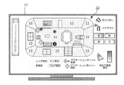
図2は、コンピュータスクリーン12上の、照明設備を制御するためのツールを伴う、本発明の単一部屋表示10の一例を示す。単一部屋表示10は、完全な部屋の直感的な二次元表示が生成されるように全ての部屋の壁13の表示と組み合わせられた部屋のフロア11の上面図である。この単一部屋表示において、光強度及び色値の分布は、ユーザにより部屋のレイアウトの上に配置され得る。分布層は、部屋のレイアウト及びレイアウト内のオブジェクトが可視のままにするように透明である。色及び強度分布は、幾つかのペイントツールを適用することによりユーザにより変更され得る。
− エリア選択ツール(スクリーンの底部)は、幾つかの操作が実行される表示の一部を選択する可能性を与える。壁選択ツールは、壁のうち1つを示すために用いられる。"全て選択"及び"フロア選択"により、完全な又は床面の分布が変更のために選択される。
− 塗りつぶしツールは、選択エリアを単一の色又は強度値でペイントする。
− エアブラシツールは、完全なエリア又は選択エリアにおいて値を変更する可能性を与える。これは、これを選択することにより操作され、色/強度分布に渡ってツールをドラッグする。エアブラシを用いるときには、エアブラシ付近にある値だけが、選択された動作に従って僅かに変更される。
FIG. 2 shows an example of a
-The area selection tool (bottom of the screen) gives the possibility to select the part of the display where several operations are performed. The wall selection tool is used to indicate one of the walls. With "Select All" and "Floor Selection", the complete or floor distribution is selected for modification.
The fill tool paints the selected area with a single color or intensity value.
-The airbrush tool gives the possibility to change the value in the complete area or selected area. This is manipulated by selecting it, dragging the tool across the color / intensity distribution. When using an airbrush, only values near the airbrush are slightly changed according to the selected action.
単一部屋表示における可能な動作は以下のとおりである。
− 光を暗く又は明るくする:分布における強度値(例えば、壁上の輝度又は仮想平面上の輝度)が減少又は増大する。
− 光をより暖かくするか又はより冷たくする。これは、より暖かい(より赤い)又はより冷たい(より青い)色に向かってシフトさせることにより行われる。
− ターゲット色及び強度を選択する。エリアツールを用いるときに、完全なエリアは、このターゲット色及び強度において塗られる。ペイントブラシを用いるときには、分布の値は、選択された色/強度ポイントに向かって徐々に変化される。
− グラデーションの生成は、ツールの組み合わせにより可能である。先ず、エリアが選択される(例えば、壁又は壁の一部)。そして、"グラデーションポイント追加"ツールが起動され、色及び強度値が選択される。"グラデーションポイント追加"ツールにより、選択エリア内の位置がクリックされる。新たな色/強度値が選択され、他の位置がクリックされる。これらのポイントの間では、色/強度値は、第1のポイントにおける第1の選択された色/強度値から、第2のポイントにおける第2の選択された値にシフトする。
Possible actions in single room display are as follows.
Make the light darker or brighter: the intensity value in the distribution (eg the luminance on the wall or the luminance on the virtual plane) is reduced or increased;
-Make the light warmer or cooler. This is done by shifting towards warmer (redder) or cooler (bluer) colors.
-Select the target color and intensity. When using the area tool, the complete area is painted at this target color and intensity. When using a paint brush, the value of the distribution is gradually changed towards the selected color / intensity point.
-Gradation can be generated by a combination of tools. First, an area is selected (eg, a wall or part of a wall). Then, the “add gradation point” tool is activated and the color and intensity values are selected. The position in the selection area is clicked by the "Add gradation point" tool. A new color / intensity value is selected and another location is clicked. Between these points, the color / intensity value shifts from the first selected color / intensity value at the first point to the second selected value at the second point.
色/強度分布が変更されたときには、照明設備の新たな制御が計算され、照明設備に送られる。これは、環境内の照明を適宜変化させる。 When the color / intensity distribution is changed, a new control of the lighting fixture is calculated and sent to the lighting fixture. This changes the lighting in the environment accordingly.
動作は、ここに示されたものに限定されない。ペイントプログラムにおいて、色分布を変更するための他のツールが存在し、これらのツールは、単一部屋表示上の色及び強度分布を変更するために用いられる(色のグラデーションを生成するための他の手法、任意の形状を選択し得るエリアセレクタ、類似の色又は強度の値をもつエリアを選択するためのマジックペン、塗りつぶしツールのような色又は強度の値を広げるためのツール、ペイントブラシ、消しゴム等)。色分布は、CIE XYZ,CIE xyYのようなデバイス独立色空間又はコンピュータRGB空間において特定され得る。xyY色空間は、壁13及びフロア11の双方の表示をカバーするために用いられ得る。xyの対はカラーポイントを示す一方で、Yは壁の輝度又は仮想表示上の輝度として解釈され得る。
Operation is not limited to that shown here. In paint programs, there are other tools for changing the color distribution, and these tools are used to change the color and intensity distribution on a single room display (others for generating color gradients). Methods, area selectors that can select any shape, magic pens for selecting areas with similar color or intensity values, tools for spreading color or intensity values such as paint tools, paint brushes, Eraser). The color distribution can be specified in a device independent color space such as CIE XYZ, CIE xyY or a computer RGB space. The xyY color space can be used to cover both
本発明を用いるために、幾つかのステップが準備のために必要とされる。これらの準備ステップは以下のものを有する。
− 部屋のフロアレイアウトを描き、これを全ての壁の表示で拡張する。家具、ドア及び窓のような細部も含まれてもよい。これは、ユーザにより、照明設備のインストーラにより、又は、3Dモデル及び壁の表示をもつこのフロアレイアウトにおけるカメラ画像を変換する自動手順を介して、行われる。場合により、壁紙の色及びテクスチャが表示に描かれてもよい。
− サンプルポイントを表示に付加する。サンプルポイントは、照明が最大又は代表的な効果をもつ場所に配置される。サンプルポイントは、ユーザ若しくはシステムのインストーラにより推定され得るか、又は、自動手順により導出され得る。いわゆるダークルームキャリブレーション手法(dark room calibration method)で自動的に導出されたときには、照明設備の制御の影響が測定され得る。これらの測定を用いることで、壁上の関心のあるポイントが導出され、単一部屋表示内に配置される。
− サンプルポイントを照明設備の制御に関連付ける。これは、色/強度値を照明設備の制御に変換するモデルをもたらす。これは、大まかな推定により行われる。例えば、色/強度分布は、(赤,緑,青の)値において特定され、サンプルポイントは、例えばLED壁面照明器具の制御が最大の効果をもつ場所に配置され、従って、サンプルポイント内のRGB値は、サンプルポイントにより示された位置で最大効果をもつLEDランプを駆動させるために直接的に用いられ得る。
In order to use the present invention, several steps are required for preparation. These preparatory steps include:
− Draw the floor layout of the room and expand it with the display of all walls. Details such as furniture, doors and windows may also be included. This is done by the user, by the lighting equipment installer, or through an automated procedure that converts the camera images in this floor layout with a 3D model and wall display. In some cases, the color and texture of the wallpaper may be drawn on the display.
-Add sample points to the display. Sample points are placed where lighting has the greatest or typical effect. The sample points can be estimated by a user or system installer or can be derived by automated procedures. When derived automatically with a so-called dark room calibration method, the influence of the control of the lighting installation can be measured. Using these measurements, points of interest on the wall are derived and placed in a single room display.
-Associate sample points with lighting fixture controls. This results in a model that translates color / intensity values into lighting fixture control. This is done by rough estimation. For example, the color / intensity distribution is specified in (red, green, blue) values and the sample points are located, for example, where the control of the LED wall luminaire has the greatest effect, and thus RGB within the sample points The value can be used directly to drive the LED lamp with maximum effect at the position indicated by the sample point.
単一部屋表示は、
− 或る時間に1つよりも多い部屋の照明分布を制御するために用いられてもよい。
− 図2の例において示された矩形の部屋とは異なる部屋の形状に対して有効であり得る。これは、フロア表示を全ての壁に対する良好な表示と組み合わせてこれをユーザに示すための良好な手法を見つけることを問題にしているに過ぎないためである。
Single room display
-May be used to control the illumination distribution of more than one room at a time.
-May be effective for different room shapes than the rectangular room shown in the example of FIG. This is because it is only a matter of finding a good way to combine the floor display with a good display on all walls and show this to the user.
図3は、一例により単一部屋表示における照明分布の処理を示している。左側において、画像は、幾つかの一般照明を部屋に供給する照明1を示し、スポット2は、壁を照らし、照明3は、壁に色分布を生成するために用いられる。照明1の効果は、フロアと平行な(仮想)表面上に有する効果によりモデル化され得る。照明2及び3の効果は、壁にこれらの効果を表すことによりモデル化され得る。仮想表示及び壁表示の双方は、図面の右側部分に示されるように、単一表示に組み合わせられ得る。この単一表示において、サンプルポイントは、問題の次元を削減するために規定され得る。サンプルポイントは、照明制御の効果が最大になる場所に配置され得る。これらのサンプルポイントにおける強度及び色の幾つかのターゲット値は、部屋内の所望の照明分布又は所望の照明雰囲気若しくはシーンを生成するためのレンダリングマシンにより処理されるべき出力信号を形成し得る。簡単に言うと、レンダリングマシンは、サンプルポイントにより表されたカラー照明分布を、照明設備の制御にマッピングすることにより、照明の制御を決定し得る。
FIG. 3 shows an illumination distribution process in a single room display according to an example. On the left, the image shows a
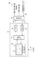
組み合わせられた表示は、表示において色及び強度分布を生成することにより照明が制御されるべき部屋の単一表示を用いるコンピュータ実行装置、例えば、ユーザインタフェースとして用いられ得るコンピュータ、タブレットPC又はハンドヘルドコンピュータ、デジタルフォトフレームに対するインタラクションを規定するために適用される。図4は、単一部屋表示10を表示するディスプレイ12、色/強度分布処理モジュール22、照明設備モデル24及び逆照明設備モデル26を有する装置18のシステム図を示す。この装置は、キーボード、タブレット、マウス、ポインタ、タッチスクリーン等からの信号である入力信号14を受信し得る。色/強度分布モデル22は、受信した入力信号14から、部屋に導入された照明設備20における色/強度分布の変化を処理し、処理された色/強度分布をモデル24に渡す。モデル24は、受信した分布を、照明設備20を駆動させるための制御値に変換する。これらの制御値は、照明設備20の照明制御値を処理するためのレンダリングマシンに出力信号16として出力される。他方、照明設備20の制御値が幾つかの外部照明制御(調光器、スイッチ)により変更されるときには、色/制御分布は、変更信号30を、受信した信号を逆モデル26のための入力信号32にマッピングするレンダリングマシンに与えることにより導出され得る。そして、変更された分布は、単一部屋表示UIデバイス12のいて表され得る。また、外部照明制御は、部屋の現在の照明を検出し得る、カメラ又はフォトセンサのようなセンサを有してもよい。それ故、単一部屋表示は、現在の照明雰囲気又はシーンをディスプレイ12上の部屋に反映させることができ、ユーザが現在の照明シーンを調節することを可能とする。
The combined display is a computer-implemented device that uses a single display of the room whose lighting is to be controlled by generating a color and intensity distribution in the display, such as a computer, tablet PC or handheld computer that can be used as a user interface, Applied to define interactions with digital photo frames. FIG. 4 shows a system diagram of an
以下、照明ユニット又はランプを部屋の照明設備に容易に統合することを可能にする、本発明の他の実施形態が示される。家の現在の照明システムは、制御のためにランプを配線することにより導入される。主として、制御は、電流で直接又は安定器を介して操作するだろう。しかしながら、最近の照明ユニット及びデバイスは、照明制御のこの従来の形式を捨て、例えば、出願人のLivingColors ランプのようなある種の遠隔制御で制御され得る。この新規なLEDランプは、強度だけでなく、照明カラーを遠隔制御で制御することを可能にする。また、他のタイプのランプが家に導入されるだろう(LEDベースのキャンドル照明、小さなLED壁面照明器具、家具への統合のためのLED照明、及び、LEDベースの効果照明)。また、消費者向け電子デバイスは、出願人のAmbiLightTV及び出願人のBXセットのような照明ユニットを有し、及び/又は、制御し得る。これは、コンピュータゲームのための効果照明を生成するために提供される。 In the following, other embodiments of the present invention will be described which allow a lighting unit or lamp to be easily integrated into a room lighting installation. The current lighting system of the house is introduced by wiring the lamp for control. Primarily, the control will operate directly with current or through a ballast. However, modern lighting units and devices abandon this conventional form of lighting control and can be controlled with some sort of remote control, such as, for example, Applicants' LivingColors lamp. This new LED lamp makes it possible to control not only the intensity but also the illumination color by remote control. Other types of lamps will also be introduced into the house (LED-based candle lighting, small LED wall luminaires, LED lighting for integration into furniture, and LED-based effect lighting). The consumer electronic device may also have and / or control lighting units such as Applicant's AmbiLightTV and Applicant's BX set. This is provided to generate effect lighting for computer games.
しかしながら、ほとんどの場合において、これらの照明生成デバイスは、これら自身が制御の分離した手法をもつ。これは、理解しやすい手法で照明雰囲気をシフトさせるためにこれら全てを用いることを困難にさせる。これら全ての照明生成デバイスを単一の照明制御システムに統合するために、照明制御の値が決定される必要がある。これらの値は、部屋にタスク又は雰囲気照明を供給する1又はそれ以上のアプリケーションにより決定され得る。利用可能な照明システムの最大の可能性を用いるために、部屋における照明の制御と効果との間の関係が与えられるべきである。 However, in most cases, these illumination generating devices have their own controlled approach. This makes it difficult to use all of them to shift the lighting atmosphere in a way that is easy to understand. In order to integrate all these lighting generation devices into a single lighting control system, the value of lighting control needs to be determined. These values may be determined by one or more applications that provide task or atmosphere lighting to the room. In order to use the full potential of the available lighting systems, a relationship between the control and effect of lighting in the room should be given.
本発明の一実施形態によれば、これらの種類の照明は、ランプの2次元グラフィック表示を環境又は部屋の2D単一部屋表示にドラッグアンドドロップすることにより、照明システム又は設備において委託(提案)され得る。ランプと一緒に、照明効果の2次元グラフィック表示が前記表示にドラッグされる。ランプ及び効果をドラッグしている間、フロアと壁との間の境界が考慮される。 According to one embodiment of the present invention, these types of lighting are commissioned (suggested) in a lighting system or facility by dragging and dropping a two-dimensional graphic representation of the lamp into a 2D single room representation of the environment or room. Can be done. Along with the lamp, a two-dimensional graphic display of the lighting effect is dragged onto the display. While dragging ramps and effects, the boundary between the floor and the wall is considered.
また、ユーザは、ランプの効果及び単一部屋表示を微調整することができる。
− ランプが配置された後に、効果の方向が微調整され得る。例えば、スポットライトの方向が示され得る。
− 壁の写真が単一部屋表示を強化するために用いられ得る。最終的に、2D表示から、ユーザが他の表示に切り替え得る。
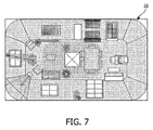
− 天井が表示の外側サイズに拡張される準3D表示(図7参照)。
− フル3D表示。これは、オブジェクト及びランプの3D表示が既知であるか又は(例えば写真から)導出され得ることを意味する。
Also, the user can fine tune the lamp effect and single room display.
-After the lamp is placed, the direction of the effect can be fine-tuned. For example, the direction of the spotlight can be indicated.
-Wall photos can be used to enhance single room display. Eventually, the user can switch from the 2D display to another display.
-Quasi-3D display where the ceiling is expanded to the outside size of the display (see Figure 7).
-Full 3D display. This means that 3D representations of objects and lamps are known or can be derived (eg from photographs).
前述したように、本発明の単一部屋表示は、フロア/天井の表示を全ての壁の表示と組み合わせる。これを行うことにより、照明システム及び環境は、単純な2次元画像として表され、所望の照明効果が、通常の画像ペイントプログラムで行われるものと類似の手法において編集され得る。図2は、ユーザが照明シーンを呼び戻し及びセーブし(スクリーンの左側)、ツール(塗りつぶし、エアブラシ)及び照明効果(色、強度)又は変更要素(暗−明、暖−冷の光)を選択することにより、照明状況を編集することができる斯様なインタフェースを示す。 As previously mentioned, the single room display of the present invention combines a floor / ceiling display with an all-wall display. By doing this, the lighting system and environment can be represented as a simple two-dimensional image, and the desired lighting effects can be edited in a manner similar to that performed with a normal image painting program. FIG. 2 shows the user recalling and saving the lighting scene (left side of the screen), selecting tools (fill, airbrush) and lighting effects (color, intensity) or changing elements (dark-light, warm-cool light) Thus, such an interface is shown where the lighting situation can be edited.
単一部屋表示におけるターゲット照明効果は、照明制御に自動的に変換され得る。単一部屋表示は、ターゲット照明効果が塗られ、ランプ制御が計算され得る表示と考えられ得る。これを行うために、ランプ制御及び配置と照明の効果との間の関係が用いられる。この関係は、例えば、モデリング及び測定のアプローチにより決定され得る。しかしながら、これらのアプローチは、大部分が、ホームユーザが実行するには非常に困難で非常に複雑である。 Target lighting effects in a single room display can be automatically converted to lighting control. A single room display can be thought of as a display where the target lighting effect can be painted and lamp control can be calculated. To do this, the relationship between lamp control and arrangement and lighting effects is used. This relationship can be determined, for example, by modeling and measurement approaches. However, these approaches are largely difficult and very complex for home users to perform.
図5において、図2において示されたものと同一の部屋が、照明設備の表示を伴ってディスプレイ12上に表示されている。スクリーンの左側では、幾つかの可能なランプ及び発光家具が、フロアの方向の又は壁から知覚される照明効果の表示と一緒に示される。このパネルから、ランプは、選択され、単一部屋表示10にドラッグされ得る。ランプを前記表示にドラッグアンドドロップするときに、フロア及び壁のランプの効果が示される。
In FIG. 5, the same room as shown in FIG. 2 is displayed on the
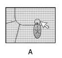
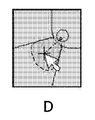
大部分の照明(確実にスポットライト)の効果は、壁、フロア又は天井の位置に向かって指向され得る。照明が表示にドロップされた後、主要な効果又はビームの中心の位置は、ランプの計画された位置又は背面位置に反映させるためにユーザにより調節され得る。(+又は×のような)記号は、ランプのこの主要な効果を示す。記号は、直線でランプに接続される。また、直線を加えたシンボルは、ウォールウォッシュ(wallwash)照明のビーム方向を示すために用いられる。図6は、LivingColorランプのポジショニングを示している。最初に、これは、表示の上にドラッグされ(a及びb)、そして、ランプは、部屋の角に配置される(c)。最後に、ランプの主要な効果は、それ自身が角に配置される(d)。効果及びランプの外観は適宜適合される。 The effect of most lighting (certainly spotlights) can be directed towards the location of the wall, floor or ceiling. After the illumination is dropped on the display, the main effect or the position of the center of the beam can be adjusted by the user to reflect the planned or back position of the lamp. A symbol (such as + or x) indicates this main effect of the lamp. The symbol is connected to the lamp in a straight line. Also, a symbol with a straight line is used to indicate the beam direction of wallwash illumination. FIG. 6 shows the positioning of the LivingColor lamp. Initially it is dragged over the display (a and b) and the lamp is placed in the corner of the room (c). Finally, the main effect of the lamp is itself placed in the corner (d). Effects and lamp appearance are adapted accordingly.
前記ケースの大部分において、これは、ランプが天井に取り付けられているか(ダウンライト)、又は、フロア又は壁に配置され、これらの効果を上向きにしているか(例えばウォールウォッシュ照明)は明らかである。しかしながら、これは、2D単一部屋表示から擬似的な又は実際の3D表示に切り替えるのに役立つ場合がある。擬似的な3D表示において、天井は、図7に示されるように、内側表示(フロア)から外側表示に拡張される。この表示において、天井の照明を示すアイコンは、天井の表示においてこれらの位置を反映させるために拡張及び移動される。 In the majority of the cases, it is clear whether the lamp is mounted on the ceiling (downlight) or placed on the floor or wall, with these effects facing up (eg wall wash lighting). . However, this may help to switch from a 2D single room display to a pseudo or actual 3D display. In the pseudo 3D display, the ceiling is expanded from the inner display (floor) to the outer display as shown in FIG. In this display, icons indicating ceiling illumination are expanded and moved to reflect these positions in the ceiling display.
単一部屋表示においてランプアイコンをドラッグ及びドロップし、ランプの主要な効果を配置することにより、部屋における効果の位置が確立される。この情報は、これらの位置に塗られたターゲット効果を、これらの位置においてこれらの効果をもつランプの制御に変換するために用いられる。 The position of the effect in the room is established by dragging and dropping the lamp icon in the single room display and placing the main effect of the lamp. This information is used to translate the target effects painted at these locations into control of lamps with these effects at these locations.
物理的なランプは、デバイスディスカバリプロトコルを用いることにより、自身を制御システムに知らせる。新たに検出されたランプは、単一部屋表示の外側の特別なエリアにおけるシステムにより配置され(図5参照;表示の左側のエリア)、そして、これらの効果が配置されるように、ユーザにより前記表示にドラッグされる。これを行うことにより、物理的なデバイスと単一部屋表示における表示との間の関係が確立される。 The physical lamp informs the control system of itself by using a device discovery protocol. Newly detected lamps are placed by the system in a special area outside the single room display (see FIG. 5; area on the left side of the display), and the user can place the effect so that these effects are placed. Dragged to the display. By doing this, a relationship between the physical device and the display in the single room display is established.
壁表示は、部屋からの写真で強化され得る。アルゴリズム及び方法は、重要な特徴(食器棚、TV、ドア、フロアと壁との間の境界)を検出し、これらの写真を壁の単一部屋表示にモーフィングするために存在する。これは、表示の外観を強化することを可能にするが、写真は、本発明の主目的のために必要とされない。つまり、導入された(及び提案された)ランプの効果を部屋に配置する。 The wall display can be enhanced with photos from the room. Algorithms and methods exist to detect important features (cupboards, TVs, doors, boundaries between floors and walls) and morph these photos into a single room display of walls. This makes it possible to enhance the appearance of the display, but photographs are not required for the main purpose of the present invention. That is, the effect of the introduced (and proposed) lamp is placed in the room.
本発明のこの実施形態は、ランプ並びに発光オブジェクト及び家具が単一の制御システム下でもたらされるべきこれらの状況に適用され得る。3D表示の代わりに、部屋、オブジェクト及び照明効果の2D単純化が行われる。これは、ホームユーザがランプを部屋のこれらの効果の位置に関連付ける手法を単純化する。ランプ特性及びアドレスと一緒に、制御と効果との間の関係が確立される。これは、雰囲気のコヒーレントシフトが与えられ得るように、他のアプリケーションが照明システムの制御を計算することを可能にする。体験を強化するアプリケーション(AmbiLight,amBX)は、これらを体験に統合するために、又は、これらを調光するために、他の照明へアクセスすることができる。この実施形態は、ユーザがこれらの環境又はターゲットルームの幾つかの単純な特性を入力することができるように、Philips Light Plannerのような、照明を計画するソフトウェアツールに統合され得る。彼らは、LivingColorランプ,AmbiLight TV,amBX照明デバイス等のような照明生成デバイス及び家具と一緒に、これらの既存の照明設備を入力し、追加のデバイスの効果及び可能性を評価することができる。 This embodiment of the invention can be applied to these situations where lamps and luminescent objects and furniture are to be brought under a single control system. Instead of 3D display, 2D simplification of rooms, objects and lighting effects is performed. This simplifies the way home users associate lamps with the location of these effects in the room. Along with the lamp characteristics and address, a relationship between control and effect is established. This allows other applications to calculate the control of the lighting system so that a coherent shift of the atmosphere can be given. Applications that enhance the experience (AmbiLight, amBX) can access other lights to integrate them into the experience or to dimm them. This embodiment can be integrated into a lighting planning software tool, such as Philips Light Planner, so that the user can enter some simple characteristics of these environments or target rooms. They can enter these existing lighting fixtures together with lighting generation devices and furniture such as LivingColor lamps, AmbiLight TV, amBX lighting devices, etc. to evaluate the effectiveness and potential of additional devices.
本発明の単一部屋表示は、部屋の照明分布を変えるための直感的な手法である。これは、照明の状況を変えるために、並びに、照明シーンを生成、セーブ及び呼び戻すために、家又は専門的な状況において用いられ得る。これは、基準の環境において照明の状況を調節するために、照明の専門家により用いられ得る。現時点では、これらは、照明設備の制御レベル上で変化を実行することに限定されるが、単一部屋表示により、これらは、設備の効果レベルの変化を行う可能性をもつ。効果レベルはより直感的であり、より多くの制御が時間的に変化され得る。また、単一部屋表示は、照明設備の制御に基づいて照明の状況を表すために用いられ得る。(例えば調光器により)ランプの制御値を変えるときには、この状況は、ツールに反映され得る。また、単一部屋表示は、ステージ上の現在の照明の状況を反映させるために、照明シーンを生成するために、及び、照明の表現をプログラムするために、映画館及びステージの環境において用いられ得る。 The single room display of the present invention is an intuitive technique for changing the illumination distribution of a room. This can be used at home or in professional situations to change the lighting situation and to create, save and recall the lighting scene. This can be used by lighting professionals to adjust lighting conditions in a reference environment. At present, these are limited to performing changes on the control level of the lighting equipment, but with a single room display they have the potential to make changes to the equipment effect level. The effect level is more intuitive and more control can be changed over time. Single room displays can also be used to represent lighting conditions based on control of lighting equipment. This situation can be reflected in the tool when changing the control value of the lamp (eg by means of a dimmer). Single room displays are also used in cinema and stage environments to reflect current lighting conditions on the stage, generate lighting scenes, and program lighting representations. obtain.
本発明の機能のうち少なくとも幾つかは、ハードウェア又はソフトウェアにより実行され得る。ソフトウェアにおける実行の場合において、単一又は複数の標準マイクロプロセッサ又はマイクロコントローラが、本発明を実行する単一又は複数のアルゴリズムを処理するために用いられ得る。 At least some of the functions of the present invention may be performed by hardware or software. In the case of implementation in software, single or multiple standard microprocessors or microcontrollers can be used to process single or multiple algorithms that implement the present invention.
"有する"という用語は、他の要素又はステップを除外するものではなく、単数表記は、複数を除外するものではない。更に、特許請求の範囲における如何なる参照符号も、本発明の範囲を限定するものとして考慮されるべきではない。 The term “comprising” does not exclude other elements or steps, and the singular does not exclude a plurality. Moreover, any reference signs in the claims should not be construed as limiting the scope of the invention.
Claims (16)
ディスプレイ上で前記照明設備をもつ3次元の部屋の複数の異なる視点の表示を2次元的に組み合わせることにより、前記部屋の単一部屋表示を生成するステップと、
生成された単一部屋表示に関する入力信号の受信及び処理を行うステップと、
処理された入力信号に応答して前記照明設備を制御するための出力信号を生成するステップとを有する、方法。 A method for controlling lighting equipment by a computer,
By combining the display of a plurality of different viewpoints of a three-dimensional room with the lighting infrastructure on a display a two-dimensional manner, and generating a single room view of the previous SL room,
Receiving and processing input signals for the generated single room display;
Generating an output signal for controlling the lighting fixture in response to the processed input signal.
前記照明設備をもつ前記部屋の前記単一部屋表示における処理された制御信号に応答して照明の色及び強度値の分布を表示するステップとを更に有する、請求項1〜9のうちいずれか一項に記載の方法。 Receiving and processing control signals from the lighting equipment;
10. Displaying lighting color and intensity value distribution in response to a processed control signal in the single room display of the room with the lighting fixture. The method according to item.
ディスプレイ上で前記照明設備をもつ3次元の部屋の複数の異なる視点の表示を2次元的に組み合わせることにより、前記部屋の単一部屋表示を生成し、生成された単一部屋表示に関する入力信号の受信及び処理を行う処理手段と、
処理された入力信号に応答して前記照明設備を制御するための出力信号を生成するように適合されたコントローラとを有する、コンピュータ実行装置。 A computer-implemented device for controlling lighting equipment,
By combining the display of a plurality of different viewpoints of a three-dimensional room with the lighting infrastructure on the display in two dimensions, generate a single room view of the front Symbol part shop, input regarding the generated single room view Processing means for receiving and processing signals;
And a controller adapted to generate an output signal for controlling the lighting fixture in response to the processed input signal.
制御信号を受信するように適合され、
受信した制御信号に応答して前記単一部屋表示における色及び/又は強度分布を変更するように適合される表示レンダリング部を更に有する、請求項14に記載の装置。 The device is
Adapted to receive control signals,
The apparatus of claim 14, further comprising a display rendering unit adapted to change a color and / or intensity distribution in the single room display in response to a received control signal.
Applications Claiming Priority (3)
| Application Number | Priority Date | Filing Date | Title |
|---|---|---|---|
| EP08104724 | 2008-07-11 | ||
| EP08104724.3 | 2008-07-11 | ||
| PCT/IB2009/052890 WO2010004488A1 (en) | 2008-07-11 | 2009-07-03 | Method and computer implemented apparatus for controlling a lighting infrastructure |
Publications (3)
| Publication Number | Publication Date |
|---|---|
| JP2011527812A JP2011527812A (en) | 2011-11-04 |
| JP2011527812A5 JP2011527812A5 (en) | 2014-01-23 |
| JP5535207B2 true JP5535207B2 (en) | 2014-07-02 |
Family
ID=41172322
Family Applications (1)
| Application Number | Title | Priority Date | Filing Date |
|---|---|---|---|
| JP2011517288A Active JP5535207B2 (en) | 2008-07-11 | 2009-07-03 | Method and computer-implemented apparatus for controlling lighting equipment |
Country Status (8)
| Country | Link |
|---|---|
| US (1) | US8494660B2 (en) |
| EP (1) | EP2298034B1 (en) |
| JP (1) | JP5535207B2 (en) |
| KR (1) | KR101700442B1 (en) |
| CN (1) | CN102090151B (en) |
| RU (1) | RU2549185C2 (en) |
| TW (1) | TW201010505A (en) |
| WO (1) | WO2010004488A1 (en) |
Families Citing this family (43)
| Publication number | Priority date | Publication date | Assignee | Title |
|---|---|---|---|---|
| CN101574018A (en) * | 2006-10-18 | 2009-11-04 | 安布克斯英国有限公司 | Method and system for detecting effect of lighting device |
| EP2529596B1 (en) * | 2010-01-29 | 2014-07-16 | Koninklijke Philips N.V. | Interactive lighting control system and method |
| WO2011126888A2 (en) * | 2010-03-30 | 2011-10-13 | Musco Corporation | Apparatus, method, and system for demonstrating customer-defined lighting specifications and evaluating permanent lighting systems therefrom |
| US20130060656A1 (en) * | 2010-05-17 | 2013-03-07 | Gary N. Bodnar | System and method for defining target color specifications |
| EP2609793A2 (en) * | 2010-08-23 | 2013-07-03 | Heinz Grether PC | An improved combined lighting and video control system |
| CA2821303C (en) * | 2010-10-15 | 2018-01-16 | Koninklijke Philips Electronics N.V. | A method and a user interaction system for controlling a lighting system, a portable electronic device and a computer program product |
| WO2012131544A1 (en) | 2011-03-29 | 2012-10-04 | Koninklijke Philips Electronics N.V. | Device for communicating light effect possibilities |
| EP2727438B1 (en) | 2011-07-01 | 2023-04-19 | Signify Holding B.V. | Lighting requirements generation system and method |
| JP5777454B2 (en) * | 2011-09-01 | 2015-09-09 | 京セラ株式会社 | Lighting control system, lighting control device, and lighting control method |
| CN103999551B (en) * | 2011-12-14 | 2018-08-07 | 飞利浦灯具控股公司 | Method and apparatus for controlling illumination |
| KR101361232B1 (en) * | 2012-02-07 | 2014-02-12 | 한국과학기술원 | Ligting control device, system based on touchscreen |
| CN103249214B (en) | 2012-02-13 | 2017-07-04 | 飞利浦灯具控股公司 | The remote control of light source |
| CN103313460B (en) * | 2012-03-15 | 2017-04-12 | 富泰华工业(深圳)有限公司 | System and method for controlling lighting equipment |
| US9089227B2 (en) * | 2012-05-01 | 2015-07-28 | Hussmann Corporation | Portable device and method for product lighting control, product display lighting method and system, method for controlling product lighting, and -method for setting product display location lighting |
| JP6479654B2 (en) * | 2012-06-11 | 2019-03-06 | フィリップス ライティング ホールディング ビー ヴィ | Method and apparatus for configuring a luminaire in a virtual environment |
| US9572226B2 (en) | 2012-07-01 | 2017-02-14 | Cree, Inc. | Master/slave arrangement for lighting fixture modules |
| US9872367B2 (en) | 2012-07-01 | 2018-01-16 | Cree, Inc. | Handheld device for grouping a plurality of lighting fixtures |
| JP6097963B2 (en) * | 2012-09-13 | 2017-03-22 | パナソニックIpマネジメント株式会社 | Lighting system |
| US10467670B2 (en) | 2012-10-24 | 2019-11-05 | Signify Holdng B.V. | Assisting a user in selecting a lighting device design |
| US9910575B2 (en) | 2012-10-24 | 2018-03-06 | Philips Lighting Holding B.V. | Assisting a user in selecting a lighting device design |
| US8912735B2 (en) * | 2012-12-18 | 2014-12-16 | Cree, Inc. | Commissioning for a lighting network |
| MY170474A (en) | 2013-02-20 | 2019-08-06 | Panasonic Ip Corp America | Control method for information apparatus and program |
| US9150147B2 (en) * | 2013-03-08 | 2015-10-06 | Caterpillar Inc. | System and method for controlling features |
| EP2779651A1 (en) * | 2013-03-12 | 2014-09-17 | TP Vision Holding B.V. | Configuring a system comprising a primary image display device and one or more remotely lamps controlled in accordance with the content of the image displayed |
| KR102152643B1 (en) | 2013-07-04 | 2020-09-08 | 엘지이노텍 주식회사 | The light system using the mobile device |
| US9801260B2 (en) * | 2013-09-20 | 2017-10-24 | Osram Sylvania Inc. | Techniques and graphical user interface for controlling solid-state luminaire with electronically adjustable light beam distribution |
| US9226373B2 (en) | 2013-10-30 | 2015-12-29 | John Joseph King | Programmable light timer and a method of implementing a programmable light timer |
| RU2653503C2 (en) | 2014-01-10 | 2018-05-10 | Филипс Лайтинг Холдинг Б.В. | Tablet-based commissioning tool for addressable lighting |
| TWI554152B (en) * | 2014-04-18 | 2016-10-11 | 太和光股份有限公司 | Remote controllable illumination system |
| TWI523578B (en) * | 2014-04-25 | 2016-02-21 | Cincon Electronics Co Ltd | A system and method for grouping a fixture on a DALI system using a handheld device |
| CN104219833B (en) * | 2014-07-31 | 2017-12-05 | 四川长虹电器股份有限公司 | The method of intelligence generation light position distribution electronic map |
| KR102288777B1 (en) * | 2014-09-22 | 2021-08-11 | 엘지이노텍 주식회사 | Apparatus and Method for Controlling Light |
| US20160170389A1 (en) * | 2014-12-12 | 2016-06-16 | Samsung Electro-Mechanics Co., Ltd. | Smart home control apparatus, smart home control method and smart home control system |
| WO2016143993A1 (en) * | 2015-03-10 | 2016-09-15 | Lg Innotek Co., Ltd. | A lighting control apparatus and method thereof |
| US20190215938A1 (en) * | 2015-11-17 | 2019-07-11 | Telelumen, LLC | Illumination theater |
| CN105554987A (en) * | 2016-01-30 | 2016-05-04 | 广州彩熠灯光有限公司 | Control system and control method for 3D visualization and gesture adjustment stage lamp |
| GB2559321B (en) * | 2017-01-10 | 2022-09-21 | Hoare Lea Llp | Graphical lighting control system |
| CN107229231B (en) * | 2017-06-07 | 2021-03-30 | 青岛海信移动通信技术股份有限公司 | Household equipment management method and device |
| KR102149180B1 (en) * | 2017-07-07 | 2020-08-28 | 한국전자통신연구원 | Method for synthesizing virtual content for augmented reality and apparatus using the same |
| US11106251B2 (en) * | 2017-07-26 | 2021-08-31 | Ledance Llc | Operation of the light management application for a mobile device with motion sensor |
| US11068144B2 (en) * | 2018-07-20 | 2021-07-20 | Ledvance Llc | Diamond shaped digitial color selection interface |
| WO2020229207A1 (en) * | 2019-05-15 | 2020-11-19 | Signify Holding B.V. | A controller for controlling a plurality of lighting units of a lighting system and a method thereof |
| CN111818705A (en) * | 2020-07-17 | 2020-10-23 | 广州彩熠灯光股份有限公司 | Lamp selection method and system based on 3D simulation, storage medium and light console |
Family Cites Families (16)
| Publication number | Priority date | Publication date | Assignee | Title |
|---|---|---|---|---|
| JPH0448585A (en) * | 1990-06-15 | 1992-02-18 | Matsushita Electric Works Ltd | Toning control apparatus |
| JPH10105591A (en) * | 1996-09-30 | 1998-04-24 | Toshiba Lighting & Technol Corp | Device and method for calculating and controlling illumination design |
| CN103017017B (en) * | 2003-04-21 | 2019-05-14 | 飞利浦固体状态照明技术公司 | Tile lighting methods and system |
| US6897622B2 (en) * | 2003-06-30 | 2005-05-24 | Mattel, Inc. | Incremental color blending illumination system using LEDs |
| RU2263356C2 (en) * | 2003-07-10 | 2005-10-27 | Андрей Викторович Синюгин | Light-technical device for dynamic lighting |
| ATE466309T1 (en) * | 2003-11-20 | 2010-05-15 | Philips Solid State Lighting | LIGHTING SYSTEM MANAGER |
| GB0328953D0 (en) * | 2003-12-12 | 2004-01-14 | Koninkl Philips Electronics Nv | Assets and effects |
| US7511697B2 (en) * | 2004-03-19 | 2009-03-31 | Omegavue, Inc. | Facility reference system and method |
| CA2579196C (en) * | 2004-09-10 | 2010-06-22 | Color Kinetics Incorporated | Lighting zone control methods and apparatus |
| JP2007103988A (en) * | 2005-09-30 | 2007-04-19 | Yokogawa Electric Corp | Coding circuit and coding apparatus |
| US8356904B2 (en) * | 2005-12-15 | 2013-01-22 | Koninklijke Philips Electronics N.V. | System and method for creating artificial atomosphere |
| WO2007110791A1 (en) * | 2006-03-24 | 2007-10-04 | Philips Intellectual Property & Standards Gmbh | Target atmosphere technique for easy light management systems and atmosphere localisation / rfid-assisted sensor network |
| JP2007311155A (en) * | 2006-05-18 | 2007-11-29 | D & M Holdings Inc | Reproducing device and reproducing system |
| US8183785B2 (en) | 2006-06-28 | 2012-05-22 | Koninklijke Philips Electronics N.V. | Method of controlling a lighting system based on a target light distribution |
| WO2008038188A2 (en) | 2006-09-29 | 2008-04-03 | Philips Intellectual Property & Standards Gmbh | Method and device for composing a lighting atmosphere from an abstract description and lighting atmosphere composition system |
| EP2119321B1 (en) | 2007-03-01 | 2011-09-07 | Philips Intellectual Property & Standards GmbH | Computer-controlled lighting system |
-
2009
- 2009-07-03 WO PCT/IB2009/052890 patent/WO2010004488A1/en active Application Filing
- 2009-07-03 JP JP2011517288A patent/JP5535207B2/en active Active
- 2009-07-03 EP EP09786504.2A patent/EP2298034B1/en active Active
- 2009-07-03 KR KR1020117003275A patent/KR101700442B1/en active IP Right Grant
- 2009-07-03 CN CN200980127036.3A patent/CN102090151B/en active Active
- 2009-07-03 RU RU2011105025/07A patent/RU2549185C2/en active
- 2009-07-03 US US13/002,592 patent/US8494660B2/en active Active
- 2009-07-08 TW TW098123085A patent/TW201010505A/en unknown
Also Published As
| Publication number | Publication date |
|---|---|
| CN102090151A (en) | 2011-06-08 |
| KR101700442B1 (en) | 2017-02-21 |
| EP2298034B1 (en) | 2019-06-12 |
| TW201010505A (en) | 2010-03-01 |
| JP2011527812A (en) | 2011-11-04 |
| CN102090151B (en) | 2014-07-23 |
| WO2010004488A1 (en) | 2010-01-14 |
| RU2011105025A (en) | 2012-08-20 |
| US8494660B2 (en) | 2013-07-23 |
| EP2298034A1 (en) | 2011-03-23 |
| KR20110039458A (en) | 2011-04-18 |
| RU2549185C2 (en) | 2015-04-20 |
| US20110112691A1 (en) | 2011-05-12 |
Similar Documents
| Publication | Publication Date | Title |
|---|---|---|
| JP5535207B2 (en) | Method and computer-implemented apparatus for controlling lighting equipment | |
| US10015865B2 (en) | Interactive lighting control system and method | |
| EP2628363B1 (en) | A method, a user interaction system and a portable electronic devicefor controlling a lighting system | |
| JP5943546B2 (en) | Remote lighting control | |
| RU2622405C2 (en) | Light source remote control | |
| JP5128489B2 (en) | User interface and method for controlling a lighting system | |
| CN109076680B (en) | Controlling a lighting system | |
| JP2010528413A5 (en) | ||
| JP2011527812A5 (en) | ||
| EP2974299A2 (en) | Configuring a system comprising a primary image display device and one or more remotely lamps controlled in accordance with the content of the image displayed | |
| US9980346B2 (en) | Lighting setting apparatus and lighting system | |
| WO2012131544A1 (en) | Device for communicating light effect possibilities | |
| JP2018510485A (en) | Color picker | |
| JP6367932B2 (en) | Device and associated method for linking selective illumination of a light source with an input | |
| WO2023286568A1 (en) | Data processing device, lighting control system, and lighting control data generation method | |
| RU2574586C2 (en) | Method and user interaction system for controlling lighting system, portable electronic device and computer programme product |
Legal Events
| Date | Code | Title | Description |
|---|---|---|---|
| A621 | Written request for application examination |
Free format text: JAPANESE INTERMEDIATE CODE: A621 Effective date: 20120702 |
|
| A977 | Report on retrieval |
Free format text: JAPANESE INTERMEDIATE CODE: A971007 Effective date: 20130829 |
|
| A131 | Notification of reasons for refusal |
Free format text: JAPANESE INTERMEDIATE CODE: A131 Effective date: 20130905 |
|
| A524 | Written submission of copy of amendment under article 19 pct |
Free format text: JAPANESE INTERMEDIATE CODE: A524 Effective date: 20131128 |
|
| TRDD | Decision of grant or rejection written | ||
| A01 | Written decision to grant a patent or to grant a registration (utility model) |
Free format text: JAPANESE INTERMEDIATE CODE: A01 Effective date: 20140327 |
|
| A61 | First payment of annual fees (during grant procedure) |
Free format text: JAPANESE INTERMEDIATE CODE: A61 Effective date: 20140422 |
|
| R150 | Certificate of patent or registration of utility model |
Ref document number: 5535207 Country of ref document: JP Free format text: JAPANESE INTERMEDIATE CODE: R150 |
|
| S111 | Request for change of ownership or part of ownership |
Free format text: JAPANESE INTERMEDIATE CODE: R313113 |
|
| R350 | Written notification of registration of transfer |
Free format text: JAPANESE INTERMEDIATE CODE: R350 |
|
| R250 | Receipt of annual fees |
Free format text: JAPANESE INTERMEDIATE CODE: R250 |
|
| R250 | Receipt of annual fees |
Free format text: JAPANESE INTERMEDIATE CODE: R250 |
|
| R250 | Receipt of annual fees |
Free format text: JAPANESE INTERMEDIATE CODE: R250 |
|
| S531 | Written request for registration of change of domicile |
Free format text: JAPANESE INTERMEDIATE CODE: R313531 |
|
| S533 | Written request for registration of change of name |
Free format text: JAPANESE INTERMEDIATE CODE: R313533 |
|
| R350 | Written notification of registration of transfer |
Free format text: JAPANESE INTERMEDIATE CODE: R350 |
|
| R250 | Receipt of annual fees |
Free format text: JAPANESE INTERMEDIATE CODE: R250 |
|
| R250 | Receipt of annual fees |
Free format text: JAPANESE INTERMEDIATE CODE: R250 |
|
| R250 | Receipt of annual fees |
Free format text: JAPANESE INTERMEDIATE CODE: R250 |