JP5534442B2 - coil - Google Patents
coil Download PDFInfo
- Publication number
- JP5534442B2 JP5534442B2 JP2010182794A JP2010182794A JP5534442B2 JP 5534442 B2 JP5534442 B2 JP 5534442B2 JP 2010182794 A JP2010182794 A JP 2010182794A JP 2010182794 A JP2010182794 A JP 2010182794A JP 5534442 B2 JP5534442 B2 JP 5534442B2
- Authority
- JP
- Japan
- Prior art keywords
- winding
- coil
- end side
- strands
- wound
- Prior art date
- Legal status (The legal status is an assumption and is not a legal conclusion. Google has not performed a legal analysis and makes no representation as to the accuracy of the status listed.)
- Active
Links
- 238000004804 winding Methods 0.000 claims description 390
- 230000002093 peripheral effect Effects 0.000 claims description 41
- 238000000034 method Methods 0.000 description 12
- 239000010410 layer Substances 0.000 description 6
- 230000012447 hatching Effects 0.000 description 5
- 238000004519 manufacturing process Methods 0.000 description 3
- RYGMFSIKBFXOCR-UHFFFAOYSA-N Copper Chemical compound [Cu] RYGMFSIKBFXOCR-UHFFFAOYSA-N 0.000 description 2
- 230000005540 biological transmission Effects 0.000 description 2
- 230000015572 biosynthetic process Effects 0.000 description 1
- 239000011248 coating agent Substances 0.000 description 1
- 238000000576 coating method Methods 0.000 description 1
- 229910052802 copper Inorganic materials 0.000 description 1
- 239000010949 copper Substances 0.000 description 1
- 230000000994 depressogenic effect Effects 0.000 description 1
- 238000010586 diagram Methods 0.000 description 1
- 230000002500 effect on skin Effects 0.000 description 1
- 230000004927 fusion Effects 0.000 description 1
- 238000007499 fusion processing Methods 0.000 description 1
- 229920002635 polyurethane Polymers 0.000 description 1
- 239000004814 polyurethane Substances 0.000 description 1
- 230000001105 regulatory effect Effects 0.000 description 1
- 102200118166 rs16951438 Human genes 0.000 description 1
- 102220240464 rs553587755 Human genes 0.000 description 1
- 229910052709 silver Inorganic materials 0.000 description 1
- 239000004332 silver Substances 0.000 description 1
- 239000002356 single layer Substances 0.000 description 1
- 229920001169 thermoplastic Polymers 0.000 description 1
- 239000004416 thermosoftening plastic Substances 0.000 description 1
- 239000002966 varnish Substances 0.000 description 1
Images


Classifications
-
- H—ELECTRICITY
- H01—ELECTRIC ELEMENTS
- H01F—MAGNETS; INDUCTANCES; TRANSFORMERS; SELECTION OF MATERIALS FOR THEIR MAGNETIC PROPERTIES
- H01F27/00—Details of transformers or inductances, in general
- H01F27/28—Coils; Windings; Conductive connections
- H01F27/2823—Wires
-
- H—ELECTRICITY
- H01—ELECTRIC ELEMENTS
- H01F—MAGNETS; INDUCTANCES; TRANSFORMERS; SELECTION OF MATERIALS FOR THEIR MAGNETIC PROPERTIES
- H01F17/00—Fixed inductances of the signal type
- H01F17/02—Fixed inductances of the signal type without magnetic core
-
- H—ELECTRICITY
- H01—ELECTRIC ELEMENTS
- H01F—MAGNETS; INDUCTANCES; TRANSFORMERS; SELECTION OF MATERIALS FOR THEIR MAGNETIC PROPERTIES
- H01F41/00—Apparatus or processes specially adapted for manufacturing or assembling magnets, inductances or transformers; Apparatus or processes specially adapted for manufacturing materials characterised by their magnetic properties
- H01F41/02—Apparatus or processes specially adapted for manufacturing or assembling magnets, inductances or transformers; Apparatus or processes specially adapted for manufacturing materials characterised by their magnetic properties for manufacturing cores, coils, or magnets
- H01F41/04—Apparatus or processes specially adapted for manufacturing or assembling magnets, inductances or transformers; Apparatus or processes specially adapted for manufacturing materials characterised by their magnetic properties for manufacturing cores, coils, or magnets for manufacturing coils
- H01F41/06—Coil winding
- H01F41/064—Winding non-flat conductive wires, e.g. rods, cables or cords
- H01F41/069—Winding two or more wires, e.g. bifilar winding
- H01F41/07—Twisting
-
- H—ELECTRICITY
- H01—ELECTRIC ELEMENTS
- H01F—MAGNETS; INDUCTANCES; TRANSFORMERS; SELECTION OF MATERIALS FOR THEIR MAGNETIC PROPERTIES
- H01F41/00—Apparatus or processes specially adapted for manufacturing or assembling magnets, inductances or transformers; Apparatus or processes specially adapted for manufacturing materials characterised by their magnetic properties
- H01F41/02—Apparatus or processes specially adapted for manufacturing or assembling magnets, inductances or transformers; Apparatus or processes specially adapted for manufacturing materials characterised by their magnetic properties for manufacturing cores, coils, or magnets
- H01F41/04—Apparatus or processes specially adapted for manufacturing or assembling magnets, inductances or transformers; Apparatus or processes specially adapted for manufacturing materials characterised by their magnetic properties for manufacturing cores, coils, or magnets for manufacturing coils
- H01F41/06—Coil winding
- H01F41/082—Devices for guiding or positioning the winding material on the former
- H01F41/084—Devices for guiding or positioning the winding material on the former for forming pancake coils
-
- H—ELECTRICITY
- H01—ELECTRIC ELEMENTS
- H01F—MAGNETS; INDUCTANCES; TRANSFORMERS; SELECTION OF MATERIALS FOR THEIR MAGNETIC PROPERTIES
- H01F41/00—Apparatus or processes specially adapted for manufacturing or assembling magnets, inductances or transformers; Apparatus or processes specially adapted for manufacturing materials characterised by their magnetic properties
- H01F41/02—Apparatus or processes specially adapted for manufacturing or assembling magnets, inductances or transformers; Apparatus or processes specially adapted for manufacturing materials characterised by their magnetic properties for manufacturing cores, coils, or magnets
- H01F41/04—Apparatus or processes specially adapted for manufacturing or assembling magnets, inductances or transformers; Apparatus or processes specially adapted for manufacturing materials characterised by their magnetic properties for manufacturing cores, coils, or magnets for manufacturing coils
- H01F41/06—Coil winding
- H01F41/082—Devices for guiding or positioning the winding material on the former
- H01F41/086—Devices for guiding or positioning the winding material on the former in a special configuration on the former, e.g. orthocyclic coils or open mesh coils
-
- H—ELECTRICITY
- H01—ELECTRIC ELEMENTS
- H01F—MAGNETS; INDUCTANCES; TRANSFORMERS; SELECTION OF MATERIALS FOR THEIR MAGNETIC PROPERTIES
- H01F27/00—Details of transformers or inductances, in general
- H01F27/28—Coils; Windings; Conductive connections
- H01F27/2871—Pancake coils
-
- H—ELECTRICITY
- H01—ELECTRIC ELEMENTS
- H01F—MAGNETS; INDUCTANCES; TRANSFORMERS; SELECTION OF MATERIALS FOR THEIR MAGNETIC PROPERTIES
- H01F37/00—Fixed inductances not covered by group H01F17/00
- H01F37/005—Fixed inductances not covered by group H01F17/00 without magnetic core
-
- H—ELECTRICITY
- H01—ELECTRIC ELEMENTS
- H01F—MAGNETS; INDUCTANCES; TRANSFORMERS; SELECTION OF MATERIALS FOR THEIR MAGNETIC PROPERTIES
- H01F38/00—Adaptations of transformers or inductances for specific applications or functions
- H01F38/14—Inductive couplings
Description
本発明は、電気機器に使用される薄型タイプに好適なコイルに関し、詳しくは、巻終り端側の巻線および巻始め端側の巻線の一方を内周側から外周側に向かって巻回する一方、他方を内周側から外周側に向けて引き出してなるコイルに関するものである。 The present invention relates to a coil suitable for a thin type used in electrical equipment, and more specifically, winding one of a winding end side winding and a winding start end side winding from the inner circumference side toward the outer circumference side. On the other hand, the present invention relates to a coil in which the other is drawn from the inner peripheral side toward the outer peripheral side.
巻始め端および巻終り端をそれぞれ内周側から外周側に向けて引き回すコイルの巻回方法として、α巻線法が一般に知られている。この巻回方法は、特許文献1に示されるように、巻線両端の中央付近に巻軸を当て、巻始め端側および巻終り端側の各巻線をそれぞれ互いに逆方向に巻回することで、巻始め端および巻終り端のいずれもが外側に引き出されたコイルを形成することができる。
An α winding method is generally known as a method of winding a coil in which the winding start end and the winding end end are routed from the inner peripheral side toward the outer peripheral side. In this winding method, as shown in
また、コイルの巻始め端側を固定し、その巻終り端側を内周側から外周側に向けて巻回し、後から巻始め端を内周側から外周側に向けて引き出す手法も知られている。この場合には、巻回コイル端面上を巻始め端の巻線が這うこととなり、その巻き始め端部側巻線の引出しライン部分は、巻始め端の巻線の線径分だけ高さ方向のサイズ(厚み)が大きくなってしまう。そこで、この問題を解決するため、該巻回コイル端面上の、巻始め端の引き出しラインに沿って、この巻回コイル端面を凹ませるようにしたものが知られている(下記特許文献2参照)
Also known is a method in which the winding start end side of the coil is fixed, the winding end end side is wound from the inner peripheral side toward the outer peripheral side, and the winding start end is subsequently pulled out from the inner peripheral side toward the outer peripheral side. ing. In this case, the winding at the winding start end rolls on the winding coil end face, and the lead-out line portion of the winding start end side winding is in the height direction by the wire diameter of the winding start end winding. The size (thickness) becomes large. Therefore, in order to solve this problem, there is known one in which the winding coil end surface is recessed along the winding line of the winding start end on the winding coil end surface (see
しかしながら、上記特許文献1のコイルの場合、巻始め端側巻線および巻終り端側巻線を互いに逆方向に巻回しており、互いの交差部では巻線が2段積み重なったような形状になるため、交差部に沿って巻線の線径の2倍の高さ部分が生じてしまうという問題がある。また、コイルが空芯コイルの場合には、巻線が2段積み重なった構造となるためコイルとして強度的に問題がある。
However, in the case of the coil of
また、特許文献1に記載されたα巻線の製造方法では、巻始め端部および巻終り端部の長さを互いにほぼ同じ長さにした状態でそれぞれを巻回させる場合に、巻回数が多い(巻線の長さが長い)コイルを巻回する際には、回転させる側であるフライヤー11a、11bを大きくしなければならなくなり、巻線機自体が大型化してしまう。
Moreover, in the manufacturing method of alpha winding described in
また、上記特許文献2の場合には、巻回コイル端面を、巻始め端側巻線の引き出しラインに沿って凹ませているため、コイル端面にはストレスがかかり、巻線の皮膜の損傷や断線などが生じる虞がある。また、コイル端面を凹ませたことに応じて、巻線が他の箇所で突出するという問題が生じてしまう。
In the case of the above-mentioned
本発明は、上述した事情に鑑みなされたもので、コイル巻線の巻始め端および巻終り端の一方を内周側から外周側に巻回し、他方を内周側から外周側に引き出してなるコイルにおいて、巻始め端側巻線および巻終り端側巻線の交差部での巻き線高さが他の部分の巻線高さに比べて大幅に高くなるのを防止し、製造も容易なコイルを提供することを目的とするものである。 The present invention has been made in view of the above-described circumstances. One of the winding start end and the winding end end of the coil winding is wound from the inner peripheral side to the outer peripheral side, and the other is drawn from the inner peripheral side to the outer peripheral side. In the coil, the winding height at the intersection of the winding start end side winding and the winding end end side winding is prevented from being significantly higher than the winding height of other portions, and the manufacturing is easy. The object is to provide a coil.
本発明のコイルは、上記目的を達成するために以下の特徴を備えてなる。 In order to achieve the above object, the coil of the present invention has the following features.
すなわち、本発明に係るコイルは、
複数の素線からなる巻線の巻終り端側の巻線および巻始め端側の巻線の一方側を内周側から外周側に向かって巻回するとともに、他方側を内周側から外周側に引き出してなるコイルにおいて、
前記一方側の巻線の複数の素線を前記コイルの巻回軸線方向である縦方向に積み重ねた状態で一緒にして巻回し、前記一方側の巻線と前記他方側の巻線の交差部分では、前記一方側の巻線は、前記複数の素線の配列状態を前記縦方向に押しつぶすようにして前記コイルの径方向である横方向に展開するのに対し、前記他方側の巻線の複数の素線は、前記一方側の巻線の配列状態が前記縦方向に押しつぶされることにより空いた前記縦方向のスペースに前記一方側の巻線に重ね合わせられて、前記縦方向の全体としての高さが、前記交差部分以外の非交差部分での高さと同等となるように調整されてなることを特徴とするものである。
また、本発明に係るコイルは、
複数の素線からなる巻線の巻終り端側の巻線および巻始め端側の巻線の一方側を内周側から外周側に向かって巻回するとともに、他方側を内周側から外周側に引き出してなるコイルにおいて、
前記複数の素線を前記コイルの巻回軸線方向である縦方向に積み重ねた状態で一緒にして巻回し、前記巻終り端側の巻線と前記巻始め端側の巻線の交差部分では、該複数の素線を前記コイルの径方向である横方向に寝かせた状態で重畳させて交差するように構成されていることを特徴とするものである。
That is, the coil according to the present invention is
While wound toward the outer peripheral side of one side from the inner circumferential side of the plurality of consisting wire winding winding completion end side of the winding and the winding start end side of the winding, the inner peripheral side and another side in In the coil drawn out from the outer periphery side,
Intersection of the one of the plurality of wires of the side of the winding wound together in a state of stacked vertically a winding axis direction of the coil, the one wherein the side of winding the other side of the winding Then, the winding on the one side expands in the horizontal direction, which is the radial direction of the coil, by crushing the arrangement state of the plurality of strands in the vertical direction, whereas the winding on the other side The plurality of strands are superposed on the one-side winding in the vertical space vacated by the arrangement state of the one-side winding being crushed in the longitudinal direction, and the entire longitudinal direction is Is adjusted to be equal to the height in a non-intersecting portion other than the intersecting portion .
The coil according to the present invention is
Periphery with, the other side from the inner peripheral side is wound toward the outer peripheral side one side of the plurality of consisting wire winding winding completion end side of the winding and the winding start end side of the winding from the inner circumferential side In the coil drawn out to the side,
The plurality of strands are wound together in a state where they are stacked in the longitudinal direction that is the winding axis direction of the coil, and at the intersection of the winding end side winding and the winding start end side winding, The plurality of strands are configured to overlap and intersect in a state where they are laid down in the lateral direction that is the radial direction of the coil .
また、前記一方側の巻線を内周側から外周側に向かって巻回するとともに、前記他方側の巻線を、曲線を描くようにして外周側に引き出し、前記交差部分が、外周に向かうにしたがって周方向にずれていくように配されてなることが好ましい。また、この場合において、前記他方側の巻線が、整数巻数分だけ、内周側から外周側に向けてコイル端面上で曲線を描くようにして引き回された後、外周側に引き出されてなることが好ましい。
Also, while wound toward the outer side of the one side of the winding from the inner circumferential side, the winding of the other side, the drawer on the outer peripheral side so as to draw a curve, the intersection is toward the outer periphery Accordingly, it is preferable that they are arranged so as to shift in the circumferential direction. Further, in this case, the other side winding is drawn out to the outer peripheral side after being drawn around the end surface of the coil by an integral number of turns so as to draw a curve on the coil end surface. It is preferable to become.
上記「複数の素線」としては、巻回される段階では互いに分離可能で巻回後に融着等の処理により互いに一体的に固定されるものの他、巻回される段階において既に一体的に固定されたもの(撚り線を含む)や、巻回される段階において互いに軽く撚りを設けておいたものなどを用いることができる。 The above-mentioned “plurality of wires” are separable from each other at the stage of winding, and are fixed to each other by a process such as fusion after winding, or already fixed at the stage of winding. Can be used (including twisted wires), or those that have been lightly twisted at the stage of winding.
また、上述の「複数の素線を縦方向に積み重ねた状態」および「複数の素線を横方向に寝かせた状態」とは、前者に比較して後者の方が複数の素線の配列状態が横方向に長くなることを意味するものである。 In addition, the above-mentioned “the state in which a plurality of strands are stacked in the vertical direction” and “the state in which a plurality of strands are laid down in the horizontal direction” are an array state of a plurality of strands in the latter compared to the former Means that it becomes longer in the horizontal direction.
なお、「複数の素線を縦方向に積み重ねた状態」から「複数の素線を横方向に寝かせた状態」とする態様としては、複数の素線間の相対的な位置関係を変えることなく複数の素線の配列状態を全体的に90度ねじったような配列状態とする態様(以下「ねじり態様」と称する)や、複数の素線間の相対的な位置関係が変わることを許容して複数の素線の配列状態を縦方向に押しつぶすようにして横方向に扁平な状態にする態様(以下「つぶし態様」と称する)がある。ねじり態様は、複数の素線が巻回される段階において既に一体的に固定されている場合に有効であり、つぶし態様は、複数の素線が巻回される段階においては互いに分離可能とされている場合に有効である。 In addition, as an aspect from "a state in which a plurality of strands are stacked vertically" to "a state in which a plurality of strands are laid in a horizontal direction", the relative positional relationship between the plurality of strands is not changed. An aspect in which the arrangement state of the plurality of strands is generally twisted by 90 degrees (hereinafter referred to as “twisting aspect”) and the relative positional relationship between the plurality of strands are allowed to change. Thus, there is an aspect (hereinafter referred to as “crushing aspect”) in which the arrangement state of a plurality of strands is crushed in the vertical direction and flattened in the horizontal direction. The twisting mode is effective when a plurality of strands are already fixed integrally at the stage where the plurality of strands are wound, and the crushing mode is separable from each other when the plurality of strands are wound. It is effective when
本発明のコイルによれば、縦方向に積み重ねた複数の素線を一緒に巻回するコイルであって、巻終り端側巻線と巻始め端側巻線の交差部分において、複数の素線を横方法に寝かせた状態で重畳させて交差させるようにしているので、交差部分での高さを従来よりも大幅に低減して、他の領域と同等の高さとすることが可能である。 According to the coil of the present invention, it is a coil that winds together a plurality of strands stacked in the vertical direction, and at the intersection of the winding end side winding and the winding start end side winding, the plurality of strands Since they are overlapped in a state where they are laid down in a horizontal manner, the height at the intersecting portion can be greatly reduced as compared with the conventional case, and the height can be made equal to other regions.
また、数本を一緒に巻回するので、表皮効果を奏することもでき、また、上記α巻線法を用いた場合のように巻線機が大型化することなく、容易に巻回することができる、という利点も有する。 Moreover, since several pieces are wound together, the skin effect can be achieved, and the winding machine can be easily wound without increasing the size as in the case of using the α winding method. It also has the advantage of being able to
以下、上述の図1〜図5,図12に基づいて、本発明に係るコイルの実施形態を説明する。 Hereinafter, embodiments of the coil according to the present invention will be described with reference to FIGS.
図1は、本実施形態に係るコイル10を示すものであり、その前提となる基本形状は図12にて表される。なお、図1は、説明の簡便のため下記交差部を4つのみ設ける態様としている。
また、本発明の説明において素線という用語を使用しているが、本明細書でいう素線とは、銅、銀などの導電性を有する線材の表面に絶縁被膜を施した1本の線材を意味するものである。
FIG. 1 shows a
In addition, although the term “wire” is used in the description of the present invention, the term “wire” in this specification refers to a single wire in which an insulating coating is applied to the surface of a conductive wire such as copper or silver. Means.
図12に示すコイル10Dは、平板空芯単層渦巻き状コイルであって(例えば、特開2007−324532に開示されている)、通常使用されている巻線の線径の約半分の線径を有する巻線を縦に2本重ねるようにし、巻終り端側は、この2本の巻線を一緒にして、内周側から外周側に向けて巻回する一方、内周側に残った巻始め端側は、コイル10Dの端面に沿って内周側から外周側に引き出すようにしたものである。なお、一般的な径の巻線1本を巻回していく場合と、図12に示すもののように、その半分の線径のものを縦に2本重ねるようにして巻回していく場合とでは、高さはほとんど変わらないものとすることができる。
A
ところで、図12に示すように、巻始め端側の巻線1Dを、コイル10Dの端面(上端面:以下同じ)に沿って内周側から外周側に引き出すようにした場合には、その巻始め端側の巻線1Dに沿った部分だけが、他のコイル端面部分よりも高くなってしまいコイルの構造上脆弱となるばかりか、コイルの薄型化を図ることが困難となってしまう。
By the way, as shown in FIG. 12, when the winding 1D on the winding start end side is drawn from the inner peripheral side to the outer peripheral side along the end surface (upper end surface: the same applies hereinafter) of the
そこで、本実施形態のコイルにおいては、巻終り端側の巻線1と巻始め端側の巻線1の交差部分では、各々の巻線1(詳しくは、巻線1を構成する2本の素線)を横方向に寝かせた状態で重畳させて交差させるように構成している。
Therefore, in the coil of this embodiment, at the intersection of the winding
すなわち、図1においては、巻始め端側の巻線1を、内周側から外周側に向けて引き出す際に、時計回りに1周だけ巻き回しながら引き出すようにしている。そして、巻始め端側の巻線1を90度だけ巻き回した位置毎(図1(a)の1、2、3、4の位置(図面中ではその数字を○内に入れ込んでいる))に、巻終り端側の次の周の巻線1と交差することになるので、この部分において、巻終わり端部側の巻線1において縦に2本積み重なった状態の素線を横に寝かせた状態とし(ねじり態様)、この上に、2本の素線を元々横に寝かせた状態で内周側から外周側に向けて引き出された、巻始め端側の巻線1を重畳させて交差させるようにしている。
That is, in FIG. 1, when the winding 1 on the winding start end side is pulled out from the inner peripheral side toward the outer peripheral side, the winding 1 is pulled out while winding only one turn clockwise. Then, for each position where the winding 1 on the winding start end side is wound by 90 degrees (
すなわち、図1(a)の1の位置は、巻終り端側の1周目の巻線1と巻始め端側の巻線1(ハッチングを入れた巻線)とが交差する位置であり、図1(a)の2の位置は、巻終り端側の2周目の巻線1と巻始め端側の巻線1とが交差する位置であり、図1(a)の3の位置は、巻終り端側の3周目の巻線1と巻始め端側の巻線1とが交差する位置であり、図1(a)の4の位置は、巻終り端側の4周目の巻線1と巻始め端側の巻線1とが交差する位置である。この図1(a)の1、2、3、4の位置では、図1(a)、(b)に示すように、巻終り端側の巻線1の2本の素線を横に寝かせた状態となるから、その巻線1は下層にのみに展開された状態となり、空いたその上層に巻始め端側の巻線1の2本の素線(図1(b)のハッチングを入れた巻線断面参照)が重畳され、トータルとして、交差部分においても、他の領域と同様の高さに調整されることになり、引出し線の高さ分だけトータルとしての高さが大きくなるといった従来の問題を解決することができる。
That is, the
しかしながら、上記交差部分においては、2本分の素線を横に寝かせた状態となるから、この部分において巻終わり端側の巻姿が素線1本分だけ外周側に突出することになる。したがって、例えば図2に示すように、巻軸2の周りに、巻始め端側の巻線1と巻終り端側の巻線1を、互いに反対方向に同じ巻回速度で同時に巻き回していくとすると、図3に示す如くその交差部4Aが径方向に直線的に並んでしまうことになり、その結果、コイル10Aの端面3Aが楕円形状となってしまう。
However, since the two strands are laid sideways at the intersecting portion, the winding shape on the winding end side protrudes to the outer peripheral side by one strand at this portion. Therefore, for example, as shown in FIG. 2, the winding 1 on the winding start side and the winding 1 on the winding end side are wound around the winding
このようにコイル10Aの端面3Aが楕円形状となるのでは、種々の不都合を生じるので、この交差部4Aが径方向に一列に並ばないようにすることが、より好ましい。例えば、図4に示すように、交差部4Bを内周側から外周側に向かってらせんを描くように配列することによって、径方向に直線的に配列されるのを防止し、コイル10Bの端面3Bが真円に近い形状となるようにする。
If the
このように交差部4Bを、コイル10Bの端面3B上で、らせんを描くように配列しつつ巻線1を巻回する方法としては、例えば、図2に示す例において、巻始め端側の巻線1の巻回角速度Aと巻終り端側の巻線1の巻回角速度Bとを、互いに異ならせて巻軸2に巻回し、交差位置が、外周側に向かうにしたがって、少しずつ周方向にずれていく方法が考えられる。結局、A,Bの巻回角速度の相違は、巻始め端側の巻線1の巻回数と巻終り端側の巻線1の巻回数の相違に帰結するから、1つの交差部から次の交差部に到るまでの両巻線1の巻回角度を相違させることによって、図3に示すように、コイル10Aの端面3Aが楕円形状となるのを防止することができる。
As a method of winding the winding 1 while arranging the intersecting
また、さらに望ましくは、巻始め端側の巻回数を丁度整数回となるようにすることによって(巻始め端側の巻線1の巻回の始点は、巻終り端側の巻線1との交差部4Bのうち最も内周側のものの位置)、コイル端面をよりよい真円形状のものにすることが可能である。
More preferably, the winding number on the winding start end side is just an integral number (the winding start point of the winding 1 on the winding start end side is the same as the winding 1 on the winding end end side). The position of the innermost side of the intersecting
上述した図1に示す実施形態のものでは、説明の便宜のため90度毎に交差部4が生じるようにしているが、実際には、巻始め端側の巻線1の巻回数と巻終り端側の巻線1の巻回数をより大きく相違させることにより、小さい角度毎に交差部が生じ、この交差部4を伝うように巻き始め端側の巻線1を渡していくことにより、巻始め端側の巻線1の引出し領域のほぼ全域に亘って、他の領域と同様の高さに調整することができる。
In the embodiment shown in FIG. 1 described above, the
例えば、巻終り端側の巻線1の巻回数を15、巻始め端側の巻線1の巻回数を1とする仕様で、互いに反対方向に巻回する場合には、巻終り端側の巻線1と巻始め端側の巻線1の交差部4Bは、巻終り端側の巻線1の1巻き毎に存在し、合計で15箇所存在することになる。そのため、巻終わり端部の巻線1を(360°−360°/15=360°−24°=)336°だけ巻回する毎に、縦に2本重ねた素線を90度ねじって、横に寝かせる交差部4を形成し、その交差部4伝いに巻始め端側の巻線1を1周に亘って沿わせていけば、巻始め端側の巻線1の引出し領域のほぼ全域に亘って、他の領域と同様の高さに調整することができるとともに、コイル10を略真円状に形成することができる。
For example, when the winding number of the winding 1 on the winding end side is 15 and the winding number of the winding 1 on the winding start end side is 1, and the windings are wound in opposite directions, The intersecting
また、このコイル10を製造する際には、前述したように、巻終り端側の巻線1と巻始め端側の巻線1のいずれか一方を時計回りに、他方を反時計回りに、互いに異なる角速度で巻くことでコイルを形成することができる。さらには、巻終り端側の巻線1を360°−24°だけ巻回した後、その巻回作業を一旦中止するとともに、巻始め端側の巻線1を交差部4まで這わせ、再度、巻終り端側の巻線1を360°−24°だけ巻回した後、その巻回作業を一旦中止するとともに、巻始め端側の巻線1を次の交差部4まで這わせるという巻回方法を採用してもよい。
Further, when manufacturing the
さらに、完成品で、巻始めを配置する箇所に対して予め、巻終り端側の巻線1を巻く際に、素線が縦に2本積み重ねるようにした巻線配列から、横方向に一旦寝かせるようにする処理(交差部作成処理)を全て最初に行なってしまい、次に、コイル端面3を上方から見て、その横方向に一旦寝かせるようにした凹部位置(交差部)に沿って、巻始め端の巻線1を配設するようにしてもよい。
Furthermore, when winding the winding
以上、本発明の実施形態を説明したが、本発明は上述の実施形態に態様が限定されるものではなく、一緒に巻回する素線本数や全交差部の数等は適宜変更が可能である。 As mentioned above, although embodiment of this invention was described, this invention is not limited to the above-mentioned embodiment, The number of strands wound together, the number of all crossing parts, etc. can be changed suitably. is there.
例えば、上記実施形態においては、2本の素線を一緒に巻回する態様について説明したが、3本あるいは4本以上の素線を一緒に束ねて巻回してもよい。 For example, in the above-described embodiment, the mode in which two strands are wound together has been described, but three or four or more strands may be bundled and wound together.
また、巻終り側端の巻回数を15、巻始め側端の巻回数を1として説明したが、これに限定されるものではなく、巻終り端側の巻回数Nを種々の値に選択することが可能であり、巻始め端側の巻回数を1にする場合に、360°−360°/N毎に、交差部が存在するようにしてもよい。 Further, the winding number at the winding end side end is 15 and the winding number at the winding start side end is 1. However, the present invention is not limited to this, and the winding number N at the winding end side is selected to various values. In the case where the number of turns on the winding start end side is set to 1, an intersection may be present every 360 ° -360 ° / N.
また、上記実施形態においては、巻線(素線)が丸線である場合について説明したが、これに限定されるものではなく、平角線または角線で巻いてもよい。その場合、断面が2:1の矩形状が望ましい。 Moreover, in the said embodiment, although the case where a coil | winding (elementary wire) was a round wire was demonstrated, it is not limited to this, You may wind with a flat wire or a square wire. In that case, a rectangular shape with a 2: 1 cross section is desirable.
この場合に、巻終り端側の巻線1を縦長に配して巻回していき、交差部において巻線1を横長になるように倒し、その上に、横長の状態に配された巻始め側端の巻線1を重ね合わせることにより、交差部においても、他の領域と同様の高さに調整されることになり、上記実施形態と同様に、引出し線の高さ分だけトータルとしての高さが大きくなるといった問題を解決することができる(図1(C)参照:図中の巻線内の数字は巻回数を表す:また、符号3´はコイルの端面を、符号10´はコイルを表す)。
In this case, the winding
ここで、5本の素線を一緒に巻回する態様のコイル10Cの概略断面を図5に示す。すなわち、巻終り端側の巻線1の内周側から1周目および3周目の巻回においては、下層が2本で上層が3本とされているが、2周目の巻回においては、交差部4Cにて5本の素線の配列状態を縦方向に押しつぶすようにして横方向に扁平となるようにすることによって下層が5本に展開され(つぶし態様)、その空いた上層には、巻始め端側の巻線1Cの素線(図5のハッチングを入れた巻線断面参照)が5本並列した状態で重ねあわされる。交差部分4Cにおいても、トータルとしての高さが、他の領域と同様に調整されることになる。
Here, FIG. 5 shows a schematic cross section of a
ただし、この5本の素線を一緒に巻回する態様においては、縦に積み重ねていた素線を交差部4Cにおいて横一列に展開するため、完全な撚り線とすることはできないが、全体としては軽く撚りを設けたものであってもよい。なお、図5では5本の素線の配列状態を見易くするために、素線間の一部に大きな隙間を設けて図示しているが、実際には素線間にこのような大きな隙間は生ぜず、密に巻回されることとなる。
However, in the mode in which these five strands are wound together, the strands that have been stacked vertically are deployed in a horizontal row at the
図6は、上述のコイル10と同様の、2本の素線を一緒に巻回する態様のコイル10Eを概略的に図示したものである((a)は平面図、(b)は(a)中のX−X線に沿った断面図)。なお、図6(b)において、断面中に入れ込んだ数値は巻線の巻回数を示している(以下の図7〜9において同じ)。
FIG. 6 schematically shows a
図6に示すコイル10Eは、巻線が2本の素線で構成されており、その巻線の巻終り端側の巻線11E((a)では最内周部のみ付番)が内周から外周まで図中反時計回りに密に巻回(略7周回)されるとともに、巻始め端側の巻線12E(ハッチングを入れた巻線)が内周から巻終り端側の巻線11Eと交差しながら図中時計回りに緩やかな渦状の曲線を描くように巻回(略1周回)されながら外周まで引き出されている。そして、巻終り端側の巻線11Eと巻始め端側の巻線12Eとの交差部分における縦方向(巻回軸線C10E方向)の厚みが他の部分の厚みと同等に構成されている。
The
すなわち、図6(b)に示すように、巻始め端側の巻線12E(ハッチングを入れた巻線)は、2本の素線が横方向(径方向)に並んだ状態で巻回されているのに対し、巻終り端側の巻線11E(○内に数字を入れた巻線)は、巻始め端側の巻線12Eと交差しない部分では2本の素線を縦方向に積み重ねた状態で巻回され、巻始め端側の巻線12Eと交差する部分では2本の素線を横方向に寝かせた状態で巻回されている(巻終り端側の巻線11Eの素線の配列状態を変更する際には、素線本数が2本と少ないため、つぶし態様とすることもねじり態様とすることも可能である)。これにより、巻終り端側の巻線11Eと巻始め端側の巻線12Eとの交差部分における縦方向の厚みが他の部分の厚みと同等に構成されることになる。 That is, as shown in FIG. 6B, the winding 12E (winding with hatching) on the winding start end side is wound in a state where two strands are arranged in the horizontal direction (radial direction). On the other hand, the winding 11E at the end of winding (the winding in which a number is entered) circles two strands in the vertical direction at a portion that does not intersect with the winding 12E on the winding start end. In the portion intersecting with the winding 12E on the winding start end side, the two strands are wound in the horizontal direction (the strand of the winding end end winding 11E). When the arrangement state is changed, since the number of strands is as small as two, it is possible to adopt a crushing mode or a twisting mode). Thereby, the thickness in the vertical direction at the intersection of the winding end end winding 11E and the winding start end winding 12E is equal to the thickness of the other portions.
図7は、8本の素線からなる巻線により構成されたコイル10Fの断面を示している。このコイル10Fでは、巻始め端側の巻線12Fは、8本の素線が横方向(径方向)に4列、縦方向(巻回軸線C10F方向)に2列で配列された状態で常に巻回されているのに対し、巻終り端側の巻線11Fは、巻始め端側の巻線12Fと交差しない部分では8本の素線が横方向に2列、縦方向に4列で配列された、縦方向に積み重ねた状態で巻回され、巻始め端側の巻線12Fと交差する部分では8本の素線が横方向に4列、縦方向に2列で配列された、横方向に寝かせた状態で巻回されている(巻終り端側の巻線11Fの素線の配列状態を変更する際には、素線本数が8本と多いため、つぶし態様とすることが好ましい)。この場合でも、巻終り端側の巻線11Fと巻始め端側の巻線12Fとの交差部分における縦方向の厚みが他の部分の厚みと同等に構成されることになる。
FIG. 7 shows a cross section of a
図8は、6本の素線からなる巻線により構成されたコイル10Gの断面を示している。このコイル10Gでは、巻始め端側の巻線12Gは、6本の素線が横方向(径方向)に6列、縦方向(巻回軸線C10G方向)に1列の配列状態で常に巻回されているのに対し、巻終り端側の巻線11Gは、巻始め端側の巻線12Gと交差しない部分では6本の素線が横方向に2列、縦方向に3列で配列された、縦方向に積み重ねた状態で巻回され、巻始め端側の巻線12Gと交差する部分では6本の素線が横方向に3列、縦方向に2列で配列された、横方向に寝かせた状態で巻回されている(巻終り端側の巻線11Gの素線の配列状態を変更する際には、素線本数が6本と多いため、つぶし態様を採用することが好ましい)。この場合でも、巻始め端側の巻線12Gと巻終り端側の巻線11Gとの交差部分における縦方向の厚みが他の部分の厚みと同等に構成されることになる。
FIG. 8 shows a cross section of a
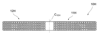
図9は、8本の素線からなる巻線により構成されたコイル10Hの断面を示している。このコイル10Hでは、巻始め端側の巻線12Hは、8本の素線が横方向(径方向)に8列、縦方向(巻回軸線C10H方向)に1列の配列状態で常に巻回されているのに対し、巻終り端側の巻線11Hは、巻始め端側の巻線12Hと交差しない部分では8本の素線が横方向に2列、縦方向に4列となる、縦方向に積み重ねた配列状態で巻回され、巻始め端側の巻線12Hと交差する部分では8本の素線が、巻始め端側の巻線12Hの8本の素線の図中下側に形成されるスペースを内周側から順に埋めるように、8本の素線の配列状態が縦方向に押しつぶされて横方向に扁平となった状態(縦方向に3列、横方向に3列または2列の配列状態)で巻回されている(つぶし態様)。この場合でも、巻終り端側の巻線11Hと巻始め端側の巻線12Hとの交差部分における縦方向の厚みが他の部分の厚みと同等に構成されることになる。
FIG. 9 shows a cross section of a
なお、つぶし態様による巻回状態の空芯コイルは、次のような巻回方法により形成される。すなわち、図2に示すように、巻線機の巻軸2の周りに、各素線がいわゆる自己融着線(例えば、ポリウレタンで被覆した銅線の外側に熱可塑性の融着性ワニス等を被せたもの)で構成されて互いに分離可能な状態にある巻線の巻始め端側の巻線と巻終り端側の巻線とを互いに逆向きに巻回していく。このとき、巻線機の巻枠(図示略)により巻軸方向(紙面に垂直な方向)の厚みを素線の所定本数分の厚み(コイル10Eの場合は2本分の厚み、コイル10F,10Hの場合は4本分の厚み、コイル10Gの場合は3本分の厚み)となるように規制しつつ、また巻始め端側の巻線の巻回角速度Aと巻終り端側の巻線の巻回角速度Bとを互いに異なるように設定して巻回を行う。これにより、巻終り端側の巻線の素線は、巻始め端側の巻線と交差しない部分では、図示せぬ巻枠の厚み分いっぱいに縦方向に延びた配列状態(縦方向に積み重ねた状態)で巻回され、巻始め端側の巻線との交差部分においては、巻始め端側の巻線の厚み(素線の縦方向の配列本数分の厚み)の分だけ、図示せぬ巻枠により厚みが規制されることにより、縦方向に押しつぶされて横方向に扁平となった配列状態(横方向に寝かせた状態)で巻回されることとなる。そして、巻回後に融着処理を行って巻軸2から取り外すことにより、つぶし態様による巻回状態の空芯コイルが形成される。
In addition, the air core coil in the wound state according to the crushing mode is formed by the following winding method. That is, as shown in FIG. 2, each wire is a so-called self-bonding wire (for example, a thermoplastic fusible varnish or the like outside the copper wire coated with polyurethane) around the winding
なお、図5,7,8,9では、好ましい態様として、巻始め端側の巻線が縦方向に1列または2列で横方向に長く並ぶように配列された状態を維持したまま内周から外周まで引き出されているように説明しているが、引き出される過程の所々で、1列から2列もしくは3列に、あるいはその逆に3列から1列等へと、巻始め端側の巻線の配列状態が変わる態様のものも本発明の実施形態に含まれるものとする。 5, 7, 8, and 9, as a preferred mode, the inner circumference is maintained while maintaining a state in which the windings on the winding start end side are arranged so as to be long in the horizontal direction in one or two rows in the vertical direction. Although it is described as being drawn from the outer circumference to the outer circumference, in the process of being drawn out, from the first row to the second row or the third row, or vice versa, from the third row to the first row, etc. A mode in which the arrangement state of the windings is changed is also included in the embodiment of the present invention.
また、巻終り端側の巻線についても同様に、全体的な配列状態を維持したまま内周から外周まで巻回されているように説明しているが、巻回過程の所々で、配列状態が崩れる(一部変化する)態様のものも本発明の実施形態に含まれるものとする。 Similarly, the winding on the winding end side is described as being wound from the inner periphery to the outer periphery while maintaining the overall arrangement state. It is assumed that the embodiment of the present invention also includes a mode in which the above is broken (partially changed).
なお、上述の空芯タイプのコイルは、薄型化の要請が強い電気機器、例えば、携帯電話や携帯型情報端末機器等における無接点電力伝送(非接触電力伝送)用のコイルとして好適であるが、本発明のコイルは、空芯コイルのみならず、ボビンやコアに巻き付ける態様のコイルにも、同様に適用することが可能である。 Note that the above-described air-core type coil is suitable as a coil for non-contact power transmission (non-contact power transmission) in an electric device that is strongly demanded to be thin, for example, a mobile phone or a portable information terminal device. The coil of the present invention can be similarly applied not only to an air-core coil but also to a coil wound around a bobbin or a core.
また、上述した態様のものは、コイルの外縁形状および空芯部の形状が共に円形とされているが、これらの形状を、R付きの矩形状あるいは楕円状とすることも可能である。図10に示すコイル10Jは、外縁形状および空芯部の形状が共にR付きの矩形状とされたものであり、図11に示すコイル10Kは、外縁形状および空芯部の形状が共に楕円状とされたものである。
In the above-described embodiment, the outer edge shape of the coil and the shape of the air core portion are both circular. However, these shapes may be rectangular or elliptical with R. The
1、1D 巻線
2 巻軸
3、3´、3A、3B、3C コイルの端面
4、4A、4B、4C 交差部
10、10´、10A、10B、10C、10D、10E、10F、10G、10H、10J、10K コイル
11E、11F、11G、11H、11J、11K 巻終り端側の巻線
12E、12F、12G、12H、12J、12K 巻始め端側の巻線
1,
Claims (4)
前記一方側の巻線の複数の素線を前記コイルの巻回軸線方向である縦方向に積み重ねた状態で一緒にして巻回し、前記一方側の巻線と前記他方側の巻線の交差部分では、前記一方側の巻線は、前記複数の素線の配列状態を前記縦方向に押しつぶすようにして前記コイルの径方向である横方向に展開するのに対し、前記他方側の巻線の複数の素線は、前記一方側の巻線の配列状態が前記縦方向に押しつぶされることにより空いた前記縦方向のスペースに前記一方側の巻線に重ね合わせられて、前記縦方向の全体としての高さが、前記交差部分以外の非交差部分での高さと同等となるように調整されてなることを特徴とするコイル。 Periphery with, the other side from the inner peripheral side is wound toward the outer peripheral side one side of the plurality of consisting wire winding winding completion end side of the winding and the winding start end side of the winding from the inner circumferential side In the coil drawn out to the side,
Intersection of the one of the plurality of wires of the side of the winding wound together in a state of stacked vertically a winding axis direction of the coil, the one wherein the side of winding the other side of the winding Then, the winding on the one side expands in the horizontal direction, which is the radial direction of the coil, by crushing the arrangement state of the plurality of strands in the vertical direction, whereas the winding on the other side The plurality of strands are superposed on the one-side winding in the vertical space vacated by the arrangement state of the one-side winding being crushed in the longitudinal direction, and the entire longitudinal direction is The coil is adjusted so that the height is equal to the height in the non-intersecting portion other than the intersecting portion .
前記複数の素線を前記コイルの巻回軸線方向である縦方向に積み重ねた状態で一緒にして巻回し、前記巻終り端側の巻線と前記巻始め端側の巻線の交差部分では、該複数の素線を前記コイルの径方向である横方向に寝かせた状態で重畳させて交差するように構成されていることを特徴とするコイル。 Periphery with, the other side from the inner peripheral side is wound toward the outer peripheral side one side of the plurality of consisting wire winding winding completion end side of the winding and the winding start end side of the winding from the inner circumferential side In the coil drawn out to the side,
The plurality of strands are wound together in a state where they are stacked in the longitudinal direction that is the winding axis direction of the coil, and at the intersection of the winding end side winding and the winding start end side winding, A coil configured to overlap and intersect the plurality of strands in a state of being laid down in a lateral direction that is a radial direction of the coil.
Priority Applications (4)
| Application Number | Priority Date | Filing Date | Title |
|---|---|---|---|
| JP2010182794A JP5534442B2 (en) | 2009-10-16 | 2010-08-18 | coil |
| US12/882,480 US8373532B2 (en) | 2009-10-16 | 2010-09-15 | Coil |
| CN2010102878845A CN102044330B (en) | 2009-10-16 | 2010-09-17 | Coil |
| EP10179433.7A EP2312595B1 (en) | 2009-10-16 | 2010-09-24 | Coil |
Applications Claiming Priority (3)
| Application Number | Priority Date | Filing Date | Title |
|---|---|---|---|
| JP2009239738 | 2009-10-16 | ||
| JP2009239738 | 2009-10-16 | ||
| JP2010182794A JP5534442B2 (en) | 2009-10-16 | 2010-08-18 | coil |
Publications (2)
| Publication Number | Publication Date |
|---|---|
| JP2011103439A JP2011103439A (en) | 2011-05-26 |
| JP5534442B2 true JP5534442B2 (en) | 2014-07-02 |
Family
ID=43466579
Family Applications (1)
| Application Number | Title | Priority Date | Filing Date |
|---|---|---|---|
| JP2010182794A Active JP5534442B2 (en) | 2009-10-16 | 2010-08-18 | coil |
Country Status (4)
| Country | Link |
|---|---|
| US (1) | US8373532B2 (en) |
| EP (1) | EP2312595B1 (en) |
| JP (1) | JP5534442B2 (en) |
| CN (1) | CN102044330B (en) |
Families Citing this family (9)
| Publication number | Priority date | Publication date | Assignee | Title |
|---|---|---|---|---|
| JP5532422B2 (en) * | 2010-07-30 | 2014-06-25 | スミダコーポレーション株式会社 | coil |
| JP2012230972A (en) * | 2011-04-25 | 2012-11-22 | Sumida Corporation | Coil component, dust inductor, and winding method of coil component |
| JP5391298B2 (en) * | 2012-03-15 | 2014-01-15 | 昭和電線デバイステクノロジー株式会社 | Litz wire coil and heating device |
| EP2709118A1 (en) * | 2012-09-14 | 2014-03-19 | Magnetic Components Sweden AB | Optimal inductor |
| US10923267B2 (en) | 2014-09-05 | 2021-02-16 | Yaroslav A. Pichkur | Transformer |
| DE102015226097B3 (en) * | 2015-12-18 | 2017-03-16 | Siemens Aktiengesellschaft | Winding arrangement, transformer and coil |
| WO2018210842A1 (en) * | 2017-05-15 | 2018-11-22 | Magcomp Ab | Coil |
| CN107516587B (en) * | 2017-09-20 | 2020-06-09 | 中国科学院微电子研究所 | Inductor and method for manufacturing same |
| WO2019107236A1 (en) * | 2017-11-28 | 2019-06-06 | 株式会社村田製作所 | Inductor and transformer |
Family Cites Families (23)
| Publication number | Priority date | Publication date | Assignee | Title |
|---|---|---|---|---|
| US512340A (en) * | 1893-07-07 | 1894-01-09 | Nikola Tesla | Coil for electro-magnets |
| US3676814A (en) * | 1970-02-06 | 1972-07-11 | Westinghouse Electric Corp | High temperature adhesive overcoat for magnet wire |
| CH625905A5 (en) * | 1977-07-05 | 1981-10-15 | Proizv Ob Uralelektrotyazhmash | Method for winding a transformer winding, and the transformer winding produced in accordance with this method |
| DE3767610D1 (en) * | 1986-02-14 | 1991-02-28 | Cornelius Lungu | ELECTRICAL COMPONENT WITH INDUCTIVE AND CAPACITIVE PROPERTIES. |
| US4794361A (en) * | 1988-03-10 | 1988-12-27 | General Motors Corporation | Coil winding method for maximum utilization of winding envelope |
| JPH06301914A (en) * | 1993-04-14 | 1994-10-28 | Canon Inc | Winding method of magnetic head coil and magnetic head |
| JP2000333433A (en) * | 1999-05-20 | 2000-11-30 | Mosutetsuku:Kk | Coil apparatus for linear motor |
| JP2002025833A (en) * | 2000-07-05 | 2002-01-25 | Tokin Corp | Electromagnetic coil |
| JP3682951B2 (en) | 2000-11-30 | 2005-08-17 | 太陽誘電株式会社 | Coil manufacturing method, coil component and manufacturing method thereof |
| JP4267951B2 (en) * | 2003-03-28 | 2009-05-27 | 古河電気工業株式会社 | coil |
| JP2004336984A (en) * | 2003-04-18 | 2004-11-25 | Denso Corp | Coil, its manufacturing method and apparatus, tees, core, and rotary electric machine |
| JP4192727B2 (en) * | 2003-08-29 | 2008-12-10 | トヨタ自動車株式会社 | Coil winding machine |
| WO2005086187A1 (en) * | 2004-03-09 | 2005-09-15 | Matsushita Electric Industrial Co., Ltd. | Transformer |
| JP2006049750A (en) | 2004-08-09 | 2006-02-16 | Okayama Giken:Kk | Air-core coil provided with lead trench and manufacturing method therefor |
| WO2007019280A2 (en) * | 2005-08-04 | 2007-02-15 | The Regents Of The University Of California | Interleaved three-dimensional on-chip differential inductors and transformers |
| EP1933340B1 (en) * | 2005-09-08 | 2012-08-01 | Sumida Corporation | Coil device, composite coil device and transformer device |
| JP4057038B2 (en) | 2006-06-05 | 2008-03-05 | メレアグロス株式会社 | Power transmission method, method for selecting and using coil of power transmission device |
| CN101325120A (en) * | 2007-06-15 | 2008-12-17 | 台达电子工业股份有限公司 | Transformer and method for winding coil thereof |
| WO2009034179A2 (en) * | 2007-09-12 | 2009-03-19 | Texas Instruments (Cork) Limited | A transformer assembly |
| JP2009158598A (en) * | 2007-12-25 | 2009-07-16 | Panasonic Electric Works Co Ltd | Planar coil and non-contact power transfer device using the same |
| JP4752879B2 (en) * | 2008-07-04 | 2011-08-17 | パナソニック電工株式会社 | Planar coil |
| US7830237B1 (en) * | 2009-08-19 | 2010-11-09 | Intelextron Inc. | Transformer |
| JP5532422B2 (en) * | 2010-07-30 | 2014-06-25 | スミダコーポレーション株式会社 | coil |
-
2010
- 2010-08-18 JP JP2010182794A patent/JP5534442B2/en active Active
- 2010-09-15 US US12/882,480 patent/US8373532B2/en active Active
- 2010-09-17 CN CN2010102878845A patent/CN102044330B/en active Active
- 2010-09-24 EP EP10179433.7A patent/EP2312595B1/en active Active
Also Published As
| Publication number | Publication date |
|---|---|
| EP2312595B1 (en) | 2014-08-13 |
| US8373532B2 (en) | 2013-02-12 |
| EP2312595A3 (en) | 2013-04-24 |
| CN102044330A (en) | 2011-05-04 |
| CN102044330B (en) | 2013-05-01 |
| EP2312595A2 (en) | 2011-04-20 |
| US20110090035A1 (en) | 2011-04-21 |
| JP2011103439A (en) | 2011-05-26 |
Similar Documents
| Publication | Publication Date | Title |
|---|---|---|
| JP5534442B2 (en) | coil | |
| JP5193292B2 (en) | Electromagnetically excitable coil | |
| CN101346782B (en) | Winding method and coil unit | |
| JP6351866B2 (en) | Rotating electric machine | |
| JP5332347B2 (en) | Coil wire rod for coil assembly of rotating electrical machine | |
| JP6245082B2 (en) | Multi-pair cable | |
| CN104167846A (en) | Pre-formed coil for making a self-supporting air gap winding, in particular helical winding of a small electric motor | |
| CN104885344A (en) | Stator for rotary electric motor | |
| JP2012124396A (en) | Toroidal coil | |
| KR20110106914A (en) | Insulated wire and coil | |
| WO2014041979A1 (en) | Coil device | |
| US20100193506A1 (en) | Litz wire coil | |
| JP4893301B2 (en) | Superconducting coil manufacturing method | |
| CN102340189B (en) | Stator, electric rotating machine and method for winding | |
| JP2009134891A (en) | Wire for coil, winding structure of wire for coil, partitioning stator, and stator | |
| JP5177545B2 (en) | Method for manufacturing coil assembly of rotating electrical machine | |
| JP2007227035A (en) | Litz wire coil | |
| JP2009148084A (en) | Armature | |
| JP2014086621A (en) | Spiral coil | |
| JP6078026B2 (en) | Winding method for electric wire of rotating electrical machine | |
| JP2013005481A (en) | Concentrated winding coil and rotary electric machine stator | |
| JP2011187717A (en) | Winding apparatus of rectangular wire, molding piece for winding apparatuses of rectangular wire, and edgewise coil | |
| JP5569743B2 (en) | Method for manufacturing coil assembly of rotating electrical machine | |
| JP2012079436A (en) | Wire core bundle and communication cable having the same | |
| JP4764156B2 (en) | Wiring cable and manufacturing method thereof |
Legal Events
| Date | Code | Title | Description |
|---|---|---|---|
| A621 | Written request for application examination |
Free format text: JAPANESE INTERMEDIATE CODE: A621 Effective date: 20130618 |
|
| A977 | Report on retrieval |
Free format text: JAPANESE INTERMEDIATE CODE: A971007 Effective date: 20140115 |
|
| A131 | Notification of reasons for refusal |
Free format text: JAPANESE INTERMEDIATE CODE: A131 Effective date: 20140124 |
|
| A521 | Request for written amendment filed |
Free format text: JAPANESE INTERMEDIATE CODE: A523 Effective date: 20140203 |
|
| A521 | Request for written amendment filed |
Free format text: JAPANESE INTERMEDIATE CODE: A523 Effective date: 20140319 |
|
| TRDD | Decision of grant or rejection written | ||
| A01 | Written decision to grant a patent or to grant a registration (utility model) |
Free format text: JAPANESE INTERMEDIATE CODE: A01 Effective date: 20140404 |
|
| R150 | Certificate of patent or registration of utility model |
Ref document number: 5534442 Country of ref document: JP Free format text: JAPANESE INTERMEDIATE CODE: R150 |
|
| A61 | First payment of annual fees (during grant procedure) |
Free format text: JAPANESE INTERMEDIATE CODE: A61 Effective date: 20140417 |
|
| S531 | Written request for registration of change of domicile |
Free format text: JAPANESE INTERMEDIATE CODE: R313531 |
|
| R350 | Written notification of registration of transfer |
Free format text: JAPANESE INTERMEDIATE CODE: R350 |
|
| R250 | Receipt of annual fees |
Free format text: JAPANESE INTERMEDIATE CODE: R250 |
|
| R250 | Receipt of annual fees |
Free format text: JAPANESE INTERMEDIATE CODE: R250 |
|
| R250 | Receipt of annual fees |
Free format text: JAPANESE INTERMEDIATE CODE: R250 |
|
| R250 | Receipt of annual fees |
Free format text: JAPANESE INTERMEDIATE CODE: R250 |
|
| R250 | Receipt of annual fees |
Free format text: JAPANESE INTERMEDIATE CODE: R250 |
|
| S531 | Written request for registration of change of domicile |
Free format text: JAPANESE INTERMEDIATE CODE: R313531 |
|
| R350 | Written notification of registration of transfer |
Free format text: JAPANESE INTERMEDIATE CODE: R350 |
|
| R250 | Receipt of annual fees |
Free format text: JAPANESE INTERMEDIATE CODE: R250 |
|
| R250 | Receipt of annual fees |
Free format text: JAPANESE INTERMEDIATE CODE: R250 |