JP5525880B2 - Scanning laser microscope - Google Patents
Scanning laser microscope Download PDFInfo
- Publication number
- JP5525880B2 JP5525880B2 JP2010065909A JP2010065909A JP5525880B2 JP 5525880 B2 JP5525880 B2 JP 5525880B2 JP 2010065909 A JP2010065909 A JP 2010065909A JP 2010065909 A JP2010065909 A JP 2010065909A JP 5525880 B2 JP5525880 B2 JP 5525880B2
- Authority
- JP
- Japan
- Prior art keywords
- laser
- dichroic mirror
- optical system
- scanning
- sample
- Prior art date
- Legal status (The legal status is an assumption and is not a legal conclusion. Google has not performed a legal analysis and makes no representation as to the accuracy of the status listed.)
- Expired - Lifetime
Links
Images


Classifications
-
- G—PHYSICS
- G02—OPTICS
- G02B—OPTICAL ELEMENTS, SYSTEMS OR APPARATUS
- G02B21/00—Microscopes
- G02B21/32—Micromanipulators structurally combined with microscopes
-
- G—PHYSICS
- G02—OPTICS
- G02B—OPTICAL ELEMENTS, SYSTEMS OR APPARATUS
- G02B21/00—Microscopes
- G02B21/0004—Microscopes specially adapted for specific applications
- G02B21/002—Scanning microscopes
- G02B21/0024—Confocal scanning microscopes (CSOMs) or confocal "macroscopes"; Accessories which are not restricted to use with CSOMs, e.g. sample holders
- G02B21/0032—Optical details of illumination, e.g. light-sources, pinholes, beam splitters, slits, fibers
-
- G—PHYSICS
- G02—OPTICS
- G02B—OPTICAL ELEMENTS, SYSTEMS OR APPARATUS
- G02B21/00—Microscopes
- G02B21/0004—Microscopes specially adapted for specific applications
- G02B21/002—Scanning microscopes
- G02B21/0024—Confocal scanning microscopes (CSOMs) or confocal "macroscopes"; Accessories which are not restricted to use with CSOMs, e.g. sample holders
- G02B21/0052—Optical details of the image generation
- G02B21/0064—Optical details of the image generation multi-spectral or wavelength-selective arrangements, e.g. wavelength fan-out, chromatic profiling
-
- G—PHYSICS
- G02—OPTICS
- G02B—OPTICAL ELEMENTS, SYSTEMS OR APPARATUS
- G02B21/00—Microscopes
- G02B21/0004—Microscopes specially adapted for specific applications
- G02B21/002—Scanning microscopes
- G02B21/0024—Confocal scanning microscopes (CSOMs) or confocal "macroscopes"; Accessories which are not restricted to use with CSOMs, e.g. sample holders
- G02B21/0052—Optical details of the image generation
- G02B21/0076—Optical details of the image generation arrangements using fluorescence or luminescence
Description
本発明は、レーザ光を試料上に走査して試料からの蛍光を光検出器により検出する走査型レーザ顕微鏡に関する。 The present invention relates to a scanning laser microscope that scans a laser beam on a sample and detects fluorescence from the sample by a photodetector.
特許文献1には、試料からの蛍光の走査画像を得るための第1の走査光学系Aと、試料の特定の部位に、例えばケージド試薬の開裂のような特異現象を発現させるための第2の走査光学系Bとを備えた走査型レーザ顕微鏡について開示されている。
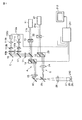
図7は、従来の走査型レーザ顕微鏡の構成を示す図である。第1の走査光学系Aのレーザ光の走査に同期して第2の走査光学系Bから試料79にレーザ光を照射して、試料79が時間的に変化する様子を測定することができる。同期は、コントロールユニット81が、第1の走査光学系Aのレーザシャッタ63と走査光学系ユニット64および光電変換素子70と、第2の走査光学系Bのレーザシャッタ72および走査光学系ユニット73を制御することで行われる。
FIG. 7 is a diagram showing a configuration of a conventional scanning laser microscope. In synchronization with the scanning of the laser beam of the first scanning optical system A, the
ケージド試薬とカルシウムイオンなどのイオン濃度に感受性を有する蛍光指示薬とを試料79に導入する。第2の走査光学系Bのレーザ光源71からのレーザ光をケージド試薬を導入した試料79に照射する。照射された部位のケージド試薬のケージド基が開裂し、内部に包含されている物質が放出される。この放出による試料79内のイオン濃度分布の変化を第1の走査光学系Aのレーザ光源61からのレーザ光により得られる蛍光画像により測定する。ケージド試薬の開裂に伴い、また、第2のレーザ光源71のレーザ光の照射によっても、試料79の蛍光指示薬がある程度の蛍光を生じる。しかし、コントロールユニット81により各レーザ光のレーザシャッタ63、72の開閉タイミングと光電変換素子70での検出タイミングを時間的に制御しているので、ケージド試薬の開裂に伴う蛍光指示薬からの蛍光強度の変化の影響を受けずに蛍光のスペクトルを光検出器で検出して蛍光画像を得ることができる。
A caged reagent and a fluorescent indicator sensitive to an ion concentration such as calcium ion are introduced into the
しかしながら、特許文献1に記載されている第1および第2の走査光学系を有する走査型レーザ顕微鏡では、第2の走査光学系のレーザ光が第1の走査光学系の光検出器にて検出されてしまう可能性がある。従って、所望の蛍光画像を得るためには更に改善の余地があった。
However, in the scanning laser microscope having the first and second scanning optical systems described in
例えば、ケージド試薬を開裂するための第2の走査光学系Bのレーザ光源71として、UVパルスレーザ(波長351nm)を用いる場合を考える。ケージド試薬を開裂するためには強い光強度が必要であるため、照射した第2の走査光学系のレーザ光の試料79からの反射光も強くなる。ダイクロイックミラー75では十分にUVパルスレーザ光の反射光が吸収されず、僅かながら第1の走査光学系Aの光路に透過してしまう。しかし、通常、第1の走査光学系Aつまり、画像取得用の走査光学系に使用されている、ダイクロイックミラー62,吸収フィルタ67等の各フィルタ類は、UVレーザの短波長域についての透過性能を考慮しているものはほとんどない。UVパルスレーザの波長は反射および透過して光電変換素子70で検出され、鮮明な蛍光画像を得ることができない。
For example, consider a case where a UV pulse laser (
同様に、ケージド試薬を開裂するための第2の走査光学系のレーザ光源71として、IRパルスレーザ(波長710nm)を用いる場合を考える。なお、このIRパルスレーザは2光子励起を引き起こすことのできるレーザとする。このIRパルスレーザについても、試料79からの強い反射光がダイクロイックミラー75で十分に反射されずに、僅かながら第1の走査光学系Aの光路に透過してしまう。通常、第1の走査光学系Aつまり、画像取得用の走査光学系に使用されている各フィルタ類は、短波長を反射,長波長を透過するロングパスフィルタを使用している場合が多い。そして、これらの吸収フィルタについては、IRの長波長域での透過特性が考慮されていない。そのため、蛍光波長より長波長のIRパルスレーザ光の波長はこれらの吸収フィルタを透過してしまい、光検出器で検出される。したがって、鮮明な蛍光画像を得ることができない。
Similarly, consider a case where an IR pulse laser (
また、上記の現象を防ぐために、特許文献1に記載されているようにレーザ照射のタイミングをずらすなどの第1および第2の走査光学系をコントロールユニット81で制御して、第2の走査光学系Bのレーザ光の影響を避けることが考えられる。しかし、この場合、走査光学系と検出光学系の制御を、同時かつ高速に行うことが必要であるため、これを実現するためには複雑な制御が必要となる。さらに、特許文献1に記載された技術では同時に2つのレーザ光を照射することができない。このため、試料79の時間的な変化を測定する際にはリアルタイム性が低下してしまう。
In order to prevent the above phenomenon, the second scanning optical system is controlled by the
本発明に係る請求項1に記載の走査型レーザ顕微鏡は、可視領域にスペクトルを有する第1のレーザ光を試料上で走査して前記試料を励起して蛍光を発生させる第1の走査光学系と、前記第1の走査光学系内の光路中に配されて前記試料からの蛍光を前記第1のレーザ光の光路から分離する第1ダイクロイックミラーと、前記第1ダイクロイックミラーで分離された蛍光を検出する光検出器と、前記第1ダイクロイックミラーと前記光検出器との間に配置され前記第1のレーザ光を遮断し前記蛍光を透過する測光フィルタと、紫外または赤外領域にスペクトルを有する第2のレーザ光を試料上の特定の部位に導入するための第2の走査光学系と、前記第1ダイクロイックミラーと前記光検出器との間に配置され前記第2のレーザ光の透過を制限する吸収フィルタと、前記吸収フィルタを複数配設することができる第1切換手段と、を備え、前記第1切換手段には、紫外領域にスペクトルを有するレーザ光の透過率を0.01%以下とする透過特性を有する吸収フィルタ、及び、赤外領域にスペクトルを有するレーザ光の透過率を0.01%以下とする透過特性を有する吸収フィルタが配設され、前記光検出器と前記測光フィルタが複数設けられ、光検出器に向けて試料からの蛍光を分光する第2ダイクロイックミラーを前記第1ダイクロイックミラーと光検出器との間に備え、前記吸収フィルタは、前記第1ダイクロイックミラーと前記第2ダイクロイックミラーとの間に配置され、前記測光フィルタはそれぞれの光検出器と前記第2ダイクロイックミラーとの間に配置された走査型レーザ顕微鏡であって、前記第2の走査光学系の第2のレーザ光の光源として、紫外領域にスペクトルを有するレーザ光源と、赤外領域にスペクトルを有するレーザ光源を有し、前記第2の走査光学系は、前記2つのレーザ光源のうちの1つを前記第2のレーザ光の光源として選択するレーザ選択手段を有し、前記第1切換手段は、前記レーザ選択手段と連動して対応する前記吸収フィルタを配置する。
The scanning laser microscope according to
本発明に係る請求項2に記載の走査型レーザ顕微鏡は、上記記載の走査型レーザ顕微鏡において、前記第1のレーザ光および試料からの蛍光を前記第2のレーザ光の光路から分離する第3ダイクロイックミラーと、前記第3ダイクロイックミラーを複数配設することができる第2切換手段と、をさらに備え、前記第2切換手段には、前記第1のレーザ光および試料からの蛍光を紫外領域にスペクトルを有する前記第2のレーザ光から分離する特性を有する第3ダイクロイックミラー、及び、前記第1のレーザ光および試料からの蛍光を赤外領域にスペクトルを有する前記第2のレーザ光から分離する特性を有する第3ダイクロイックミラーが配設され、前記第2切換手段は、前記レーザ選択手段と連動して対応する前記第3ダイクロイックミラーを前記試料と前記第1ダイクロイックミラーとの間に配置する。 According to a second aspect of the present invention, there is provided a scanning laser microscope according to the third aspect , wherein the first laser beam and the fluorescence from the sample are separated from the optical path of the second laser beam. A dichroic mirror; and a second switching unit capable of disposing a plurality of the third dichroic mirrors. The second switching unit includes the first laser beam and fluorescence from the sample in an ultraviolet region. A third dichroic mirror having a characteristic of separating from the second laser light having a spectrum, and separating the first laser light and fluorescence from the sample from the second laser light having a spectrum in an infrared region; A third dichroic mirror having a characteristic is provided, and the second switching means corresponds to the third dichroic mirror in conjunction with the laser selection means. Over the placed between said sample first dichroic mirror.
本発明に係る請求項3に記載の走査型レーザ顕微鏡は、上記記載の走査型レーザ顕微鏡において、前記第1のレーザ光および試料からの蛍光を前記第2のレーザ光の光路から分離する第3ダイクロイックミラーと、前記第3ダイクロイックミラーを複数配設することができる第2切換手段と、をさらに備え、前記第2切換手段には、前記第1のレーザ光および試料からの蛍光を紫外領域にスペクトルを有するレーザ光から分離する特性を有する第3ダイクロイックミラー、及び、前記第1のレーザ光および試料からの蛍光を赤外領域にスペクトルを有するレーザ光から分離する特性を有する他の第3ダイクロイックミラーが配設された。
本発明に係る請求項4に記載の走査型レーザ顕微鏡は、上記記載の走査型レーザ顕微鏡において、前記第2の走査光学系は、紫外または赤外領域にスペクトルを有する第2のレーザ光を選択するレーザ選択手段を有し、前記第2切換手段は、前記レーザ選択手段と連動して対応する前記第3ダイクロイックミラーを配置する。
A scanning laser microscope according to a third aspect of the present invention is the scanning laser microscope according to the third aspect , wherein the first laser beam and the fluorescence from the sample are separated from the optical path of the second laser beam. A dichroic mirror; and a second switching unit capable of disposing a plurality of the third dichroic mirrors. The second switching unit includes the first laser beam and fluorescence from the sample in an ultraviolet region. A third dichroic mirror having a characteristic of separating the laser beam having a spectrum, and another third dichroic having a characteristic of separating the first laser beam and the fluorescence from the sample from the laser beam having a spectrum in the infrared region A mirror was provided.
The scanning laser microscope according to a fourth aspect of the present invention is the above-described scanning laser microscope, wherein the second scanning optical system selects the second laser light having a spectrum in the ultraviolet or infrared region. The second switching means arranges the corresponding third dichroic mirror in conjunction with the laser selection means.
本発明によれば、検出光路上に特異現象を発現させるレーザ光を遮断するフィルタを配置することで、画像取得用レーザ光と特異現象発現用レーザ光を同時に照射でき、鮮明な蛍光画像を取得できる走査型レーザ顕微鏡を提供できる。 According to the present invention, by arranging a filter for blocking a laser beam that causes a specific phenomenon on the detection optical path, it is possible to simultaneously irradiate a laser beam for acquiring an image and a laser beam for expressing a specific phenomenon, thereby acquiring a clear fluorescent image. A scanning laser microscope can be provided.
また、画像取得用の走査光学系および特異現象を発現させる走査光学系の結像レンズを別構成とすることで、システムアップを行いやすい走査型レーザ顕微鏡を提供できる。 In addition, by providing a scanning optical system for image acquisition and an imaging lens for a scanning optical system that causes a specific phenomenon to be provided separately, a scanning laser microscope that facilitates system up can be provided.
[参考の実施の形態(第1の実施の形態)]
本発明の第1の実施の形態について説明する。図1は本発明に係る走査型レーザ顕微鏡の構成図である。
[ Reference Embodiment ( First Embodiment ) ]
A first embodiment of the present invention will be described. FIG. 1 is a configuration diagram of a scanning laser microscope according to the present invention.
この走査型レーザ顕微鏡は、第1の走査光学系Aと第2の走査光学系Bを備えている。第1の走査光学系Aは、第1のレーザ光源11から出力されるレーザ光11aで試料29面上を走査する観察用の光学系である。第2の走査光学系Bは試料の特定部位に特異現象を発現させるための光学系である。即ち、第2の走査光学系Bは、第2のレーザ光源21から出力されるレーザ光21aを試料29の任意の位置に照射して、ケージド試薬を解除させる。
This scanning laser microscope includes a first scanning optical system A and a second scanning optical system B. The first scanning optical system A is an observation optical system that scans the surface of the
第1の走査光学系Aは、第1のレーザ光源11、ダイクロイックミラー12、第1のレーザシャッタ13、第1の走査光学ユニット14、瞳投影レンズ15およびミラー16から構成される。さらに第1の走査光学系Aのダイクロイックミラー12の分岐光路上には、検出光学系Cが配置されている。この検出光学系Cは、吸収フィルタ31、ダイクロイックミラー17、ミラー18、蛍光測光フィルタ19aおよび19b、共焦点レンズ110aおよび110b、共焦点絞り111aおよび111bおよび光電変換素子112aおよび112bにより構成される。
The first scanning optical system A includes a first
吸収フィルタ31は、試料29からの第2の走査光学系Bのレーザ光21aの反射光を吸収する特性を有する。通常、ケージド試薬の解除にはUV光が使用される。そこで、以下のようなレーザ光源を使用することが考えられる。
The
(a)第2のレーザ光源21として、UVパルスレーザ(波長351nm)を使用する。
(A) A UV pulse laser (
(b)第2のレーザ光源21として、IRパルスレーザ(波長710nm)を使用する。なお、IRパルスレーザは、2光子励起現象を引き起こすことのできるレーザとする。
(B) An IR pulse laser (
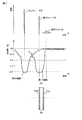
従って、吸収フィルタ31の特性としては、上記のレーザ光を吸収する特性を有するものであり、具体的には図2に示すような特性を有するフィルタを用いる。
Therefore, the
図2(a)は、UVパルスレーザ(波長351nm)を遮断するフィルタ特性を示す図であり、図2(b)は、IRパルスレーザ(波長710nm)を遮断するフィルタ特性を示す図である。
FIG. 2A is a diagram illustrating filter characteristics for blocking the UV pulse laser (
第2の走査光学系Bは、ケージド試薬を解除させるための第2のレーザ光源21、第2のレーザシャッタ22、第2の走査光学ユニット23、瞳投影レンズ24およびダイクロイックミラー25から構成される。第1の走査光学系Aの光軸と第2の走査光学系の光軸とは、ダイクロイックミラー25により合成され、結像レンズ26、対物レンズ27に導かれる。また、瞳投影レンズ15および瞳投影レンズ24の焦点位置は、結像レンズ26の焦点位置と一致するように配置されている。試料29はステージ28上に置かれている。
The second scanning optical system B includes a second
ここで、第1のレーザ光源11と第2のレーザ光源21として考えられる組合せと、その条件に適合するダイクロイックミラー25の特性は以下のとおりである。
Here, the possible combinations of the first
第1のレーザ光源11に可視連続レーザ(波長488nm)、第2のレーザ光源21としてUVパルスレーザ(波長351nm)を用いる場合は、ダイクロイックミラー25の透過率波長特性は、図3(a)に示すように、可視連続光レーザ(波長488nm)及びその蛍光(波長530nm)を透過し、UVパルスレーザ(波長351nm)を反射する特性を有している。
When a visible continuous laser (
第1のレーザ光源11に可視連続レーザ(波長488nm)、第2のレーザ光源21としてIRパルスレーザ(波長710nm)を用いる場合は、ダイクロイックミラー25の透過率波長特性は、図3(b)に示すように、ダイクロイックミラー25は、可視連続光レーザ(波長488nm)及びその蛍光(波長530nm)を透過し、IRパルスレーザ(波長710m)を反射する特性を有している。
When a visible continuous laser (
第1のレーザ光源11にIRパルスレーザ(波長850nm)、第2のレーザ光源21としてIRパルスレーザ(波長710nm)を用いる場合は、ダイクロイックミラー25の透過率波長特性は、図3(c)に示すように、IRパルスレーザ(波長850nm)及び波長530nmの蛍光を透過し、IRパルスレーザ(波長710nm)を反射する特性を有している。
When an IR pulse laser (
なお、ここで使用するIRパルスレーザは、2光子励起現象を引き起こすことのできるレーザである。 The IR pulse laser used here is a laser that can cause a two-photon excitation phenomenon.
前記第1のレーザシャッタ13、第2のレーザシャッタ22、第1の光学走査ユニット14、第2の光学走査ユニット23、光電変換素子112aおよび光電変換素子112bは、コントロールユニット211に接続されている。このコントロールユニット211には、CRTディスプレイ212が接続されている。コントロールユニット211は後述するように、第2の走査光学系Bからのレーザ光の試料29への照射を第1の走査光学系Aの走査に同期させる。
The
次に、このように構成した走査型レーザ顕微鏡の作用を説明する。第1のレーザ光源11からのレーザ光11aは、コントロールユニット211により開閉制御される第1のレーザシャッタ13が開状態のときに通過する。そしてレーザ光11aは、第1の走査光学ユニット14へ導かれ、コントロールユニット211により制御されて任意の方向に走査される。レーザ光11aはさらに、瞳投影レンズ15、ミラー16、ダイクロイックミラー25、結像レンズ26、対物レンズ27を介して、試料29の断面210上に集光され、試料の断面210内を2次元走査する。
Next, the operation of the scanning laser microscope configured as described above will be described. The
試料29には、第1のレーザ光源11の波長によって励起される蛍光指示薬(例えばfluo−3、励起波長488m,蛍光波長530nm)が導入されている。試料の断面210内をレーザ光が走査することにより、蛍光指示薬が励起されて蛍光を生じる。対物レンズ27に入射した蛍光は、上記レーザ光と同じ光路を逆向きに進み、対物レンズ27、結像レンズ26、ダイクロイックミラー12へ導かれる。ダイクロイックミラー12は、第1のレーザ光源11からのレーザ光11aの波長より長波長の光を反射する特性を備えている。従って、これにより上記蛍光はダイクロイックミラー12により反射され、検出光学系Cへ導入される。
In the
検出光学系Cにおいて、試料29が多重染色されている場合、吸収フィルタ31を通過した蛍光は、ダイクロイックミラー17により各波長の蛍光に分光される。分光した光のうち特定の波長の光が、それぞれ蛍光測光フィルタ19aおよび19bを通過し、共焦点レンズ110aおよび110bで集光される。そして、試料の断面210と光学的に共役な位置に設けられている共焦点絞り111aおよび111bによって、試料の断面210からの光のみが光電変換素子112aおよび112bへ入射する。
In the detection optical system C, when the
光電変換素子112aおよび112bからの出力信号は、コントロールユニット211へ導かれる。出力信号は走査制御に同期してデジタル信号に変換され、走査位置に対応してCRTディスプレィ画面212上に表示される。表示された画像は、試料の断面210での蛍光輝度の2次元分布である蛍光画像、すなわち所望のイオン濃度の断面210内での分布を示している。
Output signals from the
一方、第2のレーザ光源21からのレーザ光21aは、コントロールユニット211が開閉制御する第2のレーザシャッタ22が開状態のときに通過する。レーザ光21aは、第2の走査光学ユニット23、瞳投影レンズ24、ダイクロイックミラー25を介して第1の走査光学系Aからのレーザ光11aと同じ光軸上を進行する。そしてレーザ光21aは、結像レンズ26、対物レンズ27を通過して、試料29の断面210上に照射される。この時、コントロール211により第2の走査光学ユニット23を制御することで、第1の走査光学系Aの走査位置と独立に断面210内での照射位置を選択することができる。
On the other hand, the
第2のレーザ光源21からのレーザ光21aが、ケージド試薬を導入した試料29に照射されると、照射された部位のケージド試薬のケージド基が開裂し、内部に包含されている物質が放出される。この放出による試料29内の上記イオン濃度分布の変化を、第1の走査光学系Aにより得られる蛍光画像により測定できる。
When the
このとき、試料29上で反射した第2のレーザ光源21からのレーザ光21aを含む反射光は、試料29の断面210上で発生した蛍光と同じ光路を進行する。ダイクロイックミラー25へ達したレーザ光21aを含む反射光のうち数%の光はダイクロイックミラー25を透過して第1の走査光学系Aの光路へ導入される。第1の走査光学系Aへ導入された第2のレーザ光を含む反射光は、ミラー16、瞳投影レンズ15、走査光学ユニット14を通過して、ダイクロイックミラー12で反射され検出光学系の光路へ導かれる。
At this time, the reflected light including the
ダイクロイックミラー12で反射されたレーザ光21aを含む反射光は、予め検出光学系Cの光路上に配置されたレーザ光21aを吸収する特性を備えた吸収フィルタ31で吸収される。従って、蛍光のみが吸収フィルタ31を通過し、光電変換素子112a、112bで検出されるようになる。
The reflected light including the
ここで、本実施の形態において用いる吸収フィルタ31の透過特性について説明する。
Here, the transmission characteristics of the
試料29に照射される励起レーザ光である第2の走査光学系Bからのレーザ光21aの強度に対して、試料29より発生する蛍光の強度は非常に弱い。従って、試料29で反射したレーザ光21aが試料や途中の光学系で反射することによって減衰したとしても、試料29から発生して検出器112a、112bに向う蛍光の強度に比較して、1000倍または、それ以上となることが多い。従って、これらの反射したレーザ光21aの影響を受けずに蛍光画像を鮮明に取得するには蛍光を透過させる吸収フィルタ特性として、反射したレーザ光21aの透過率を少なくとも0.01%以下にする必要がある。
The intensity of the fluorescence generated from the
ところで、このような特性を実現するために、多層膜コーティングを用いた干渉フィルタが使用される。干渉フィルタは、屈折率や膜厚の異なる層を多数重ねあわせ、光を干渉させて透過率を制御する。しかし干渉フィルタは、波長帯域に対してフラットな透過率特性を実現するのは困難なため、通常は、目的とする透過波長と遮断波長を設定し、その波長で所望の特性が得られるように製造される。従来、蛍光波長を選択する吸収フィルタとして実際に製造されるものは、蛍光に対応する励起波長のみを透過率0.01%以下とするのが一般的であった。 By the way, in order to realize such characteristics, an interference filter using a multilayer coating is used. The interference filter superimposes a large number of layers having different refractive indexes and film thicknesses, and interferes light to control the transmittance. However, since it is difficult to achieve a flat transmittance characteristic with respect to a wavelength band, an interference filter usually sets a desired transmission wavelength and cutoff wavelength so that desired characteristics can be obtained at that wavelength. Manufactured. Conventionally, what is actually manufactured as an absorption filter for selecting a fluorescence wavelength generally has a transmittance of 0.01% or less only for the excitation wavelength corresponding to the fluorescence.
即ち、従来の吸収フィルタは、「蛍光を取り出す機能」を有するフィルタであって、本実施の形態で用いる吸収フィルタ31が更に有する、第2走査光学系を設けた場合の「第2レーザ光」を遮断する機能を備えていないと考えられる。
That is, the conventional absorption filter is a filter having a “fluorescence extraction function”, and the “second laser light” when the second scanning optical system further provided in the
図4(a)は、本実施の形態の吸収フィルタの特性を説明する図である。 FIG. 4A is a diagram for explaining the characteristics of the absorption filter of the present embodiment.
図4(a)では、第1のレーザ光を可視連続レーザ光(波長488nm)、第2のレーザ光をUVパルスレーザ光(波長351nm)、試料からの光を蛍光(波長530nm)として表わしている。
In FIG. 4A, the first laser beam is represented as visible continuous laser beam (
図4(a)の上部には、第1のレーザ光、第2のレーザ光及び試料からの光の強度分布を示している。この図に示すように、第2のレーザ光の強度は、第1のレーザ光の強度よりも強い場合が多い。これは、第2のレーザ光が試料に刺激を与えたり、試料を操作する目的で用いられるためである。このことから、第2のレーザ光を第1のレーザ光よりも確実に遮断する必要性が高いことがわかる。 In the upper part of FIG. 4A, intensity distributions of the first laser beam, the second laser beam, and the light from the sample are shown. As shown in this figure, the intensity of the second laser beam is often stronger than the intensity of the first laser beam. This is because the second laser beam is used for the purpose of stimulating the sample or operating the sample. From this, it can be seen that there is a higher necessity to block the second laser light more reliably than the first laser light.
図4(a)の下部には、本実施の形態の吸収フィルタの透過特性の概念を示している。 The concept of the transmission characteristics of the absorption filter of the present embodiment is shown in the lower part of FIG.
上述のように、本実施の形態の吸収フィルタは2つの機能を備えている。即ち、「蛍光を取り出す機能」である第1の機能を実現するための透過機能と、「第2のレーザ光を遮断する機能」である第2の機能を実現するための透過特性と備えている。この2つの機能を備えることで明瞭な蛍光像を得ることが可能となる。 As described above, the absorption filter of the present embodiment has two functions. That is, a transmission function for realizing the first function, which is “a function of extracting fluorescence”, and a transmission characteristic for realizing the second function, which is a “function for blocking the second laser light”, are provided. Yes. By providing these two functions, a clear fluorescent image can be obtained.
本実施の形態の吸収フィルタを実現するために、図1に示すように「蛍光を取り出す機能」(第1の機能)を持つ蛍光測光フィルタ19a、19bと「第2レーザ光遮断機能」(第2の機能)を持つ吸収フィルタ31とをそれぞれ配置する。また図4(b)に示すように、一枚のガラスの両面にそれぞれの機能をもつフィルタ膜31a、32aを生成しても良い。図4(b)に示すフィルタを使用する場合、図1のフィルタ19a、19bの代わりに使用すれば良い。このとき、フィルタ31は必要でない。
In order to realize the absorption filter of the present embodiment, as shown in FIG. 1, the
このように、検出光学系Cに上述の透過特性を持つ吸収フィルタ31を用いて構成することで、試料29からの反射光に含まれるレーザ光21aを確実に除去することができ、鮮明な蛍光画像が得られる。また第1のレーザ光11aと第2のレーザ光21aの同時照射も可能となる。更に、試料29が多重染色されている場合、図1に示すように吸収フィルタ31は検出光学系Cの共通光路へ配設すれば良いため、容易に構成することができる。
In this way, by configuring the detection optical system C using the
[第2の実施の形態]
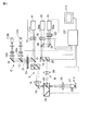
本発明の第2の実施の形態について説明する。図5は本発明に係る走査型レーザ顕微鏡の構成図である。第1の実施形態と同一部分には、同一符号を付してその詳しい説明は省略する。
[Second Embodiment]
A second embodiment of the present invention will be described. FIG. 5 is a block diagram of a scanning laser microscope according to the present invention. The same parts as those in the first embodiment are denoted by the same reference numerals, and detailed description thereof is omitted.
第2の実施の形態では、第2の走査光学系Bのレーザには、UVパルスレーザ34と波長可変可能で2光子励起現象を引き起こすことができるIRパルスレーザ35とが用いられる。そして、これらのレーザ34、35はレーザシャッタ36および37の開閉制御により選択して使用することができる。また、第1の走査光学系Aからのレーザ光11aの光軸と第2の走査光学系Bからのレーザ光34aもしくは35aの光軸とを合成する位置にダイクロイックミラー25が配置されている。ダイクロイックミラー25は、複数のダイクロイックミラーを備えることのできる電動ターレット32に少なくとも一つ配設されている。
In the second embodiment, the laser of the second scanning optical system B uses a
さらに、第2の走査光学系Bのレーザ光源からのレーザ光34aもしくは35aを遮断するために、吸収フィルタ31が検出光学系Cの光路上に配置されている。この吸収フィルタ31は複数の吸収フィルタを備えることのできる電動ターレット33に少なくとも一つ配設されている。
Further, an
なお、電動ターレット32および33は、通常、回転式であるが必要に応じてスライダ式としても良い。
The
また、前記電動ターレット32、33、レーザシャッタ36、37は、それぞれコントローラーユニット211に接続され、コントローラーユニット211より制御が可能である。
The
このように構成した走査型レーザ顕微鏡の作用を説明する。第2の走査光学系Bのレーザ光源としてUVパルスレーザ34を用いる。第1の走査光学系Aのレーザ光源11からレーザ光11aおよび、第2の走査光学系Bのレーザ光源より出力されるUVパルスレーザ光34aは、第1の実施の形態で述べたと同様に各光学素子を通過する。そして、第1の走査光学系Aからのレーザ光11aの光軸と第2の走査光学系BからのUVパルスレーザ光34aの光軸が、ダイクロイックミラー25で合成される。ダイクロイックミラー25は、第1の走査光学系Aからのレーザ光11aを透過し、第2の走査光学系Bからのレーザ光であるUVパルスレーザ光34aを反射するような特性を有する。ダイクロイックミラー25は、レーザシャッタ36の開閉動作と連動して動作する電動ターレット32によって光路上に配置される。
The operation of the thus configured scanning laser microscope will be described. A
ダイクロイックミラー25で合成された第1および第2のレーザ光源からの各レーザ光は、第1の実施の形態と同様に、結像レンズ26,対物レンズ27を透過して、試料29の断面210上に集光される。UVパルスレーザ光34aによりケージド試薬が解除され、第1の走査光学系Aからのレーザ光11aにより、蛍光指示薬が励起されて蛍光が発生する。
The laser beams from the first and second laser light sources synthesized by the
試料29より発生した蛍光と試料からの反射光であるUVパルスレーザ光34aが、第1の走査光学系Aの光路を逆方向に進行し、ダイクロイックミラー12を介して蛍光およびUVパルスレーザ光34aの反射光が検出光学系Cに導入される。
The fluorescence generated from the
検出光学系Cに導入された蛍光およびUVパルスレーザ光34aのうち蛍光は、吸収フィルタ31を通過し、UVパルスレーザ光は吸収フィルタ31で吸収される。尚、電動ターレット33はレーザシャッタ36の開閉動作と連動して動作し、UVパルスレーザ光を吸収するような透過特性を有する吸収フィルタ31を光路上に予め配置する。
Of the fluorescence and UV pulse laser light 34 a introduced into the detection optical system C, the fluorescence passes through the
吸収フィルタ31を通過した蛍光は第1の実施の形態で述べたと同様に各光学素子を通過する。そして蛍光は、光電変換素子112aおよび112bで検出される。検出信号はコントローラーユニット211で信号処理された後、CRTディスプレイ212上に表示される。
The fluorescence that has passed through the
一方、ケージド試薬を解除するため、もしくは、タンパク質(例えばYFP)を発現させた試料を光褪色させるために、第2の走査光学系Bのレーザ光としてIRパルスレーザ35を用いる場合がある。この場合、第1の走査光学系Aからのレーザ光の光軸と第2の走査光学系BからのIRパルスレーザ光35aを合成するダイクロイックミラー25は、第1の走査光学系Aからのレーザ光11aを透過し、IRパルスレーザ光35aを反射する透過特性を有する。そして電動ターレット32は、レーザシャッタ37の開閉動作と連動してダイクロイックミラー25を光路上に予め配置する。
On the other hand, the
また、検出光学系Cにおいても、吸収フィルタ31は蛍光を透過し、反射光であるIRパルスレーザ光35aを吸収するような透過特性を有している。そして、電動ターレット33がレーザシャッタ37の開閉動作と連動して吸収フィルタ31を予め光路上に配置する。
Also in the detection optical system C, the
このように第2の実施の形態においては、第1の走査光学系Aからのレーザ光の光軸と第2の走査光学系Bからのレーザ光の光軸とを合成するダイクロイックミラー25を電動ターレット上に備えている。更に、検出光学系Cに試料29からの反射光である第2の走査光学系Bのレーザ光を吸収するような吸収フィルタ31を電動ターレット33に備えている。そして、前記電動ターレット32および33をレーザシャッタ36および37の開閉動作と連動して動作させる。これによって、ケージド試薬の解除等に使用する第2の走査光学系Bのレーザ光源として、UVパルスレーザ34もしくはIRパルスレーザ35のいずれかを選択して使用することが可能なシステムを提供することができる。
Thus, in the second embodiment, the
また、電動ターレット32、33に代えて手動ターレットを用いれば、同様の性能を有するシステムを安価で提供することができる。
If a manual turret is used instead of the
[参考の実施の形態(第3の実施の形態)]
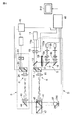
本発明の第3の実施の形態について説明する。図6は本発明に係る走査型レーザ顕微鏡の構成図である。第1および第2の実施形態と同一部分には、同一符号を付してその詳しい説明は省略する。
[ Reference Embodiment ( Third Embodiment ) ]
A third embodiment of the present invention will be described. FIG. 6 is a block diagram of a scanning laser microscope according to the present invention. The same parts as those in the first and second embodiments are denoted by the same reference numerals, and detailed description thereof is omitted.
本実施の形態の走査型レーザ顕微鏡は、観察用の第1の走査光学系Aの結像レンズ41と第2の走査光学系Bの結像レンズ43をそれぞれ独立に配置し、対物レンズ27を共用する構成になっている。
In the scanning laser microscope of the present embodiment, the
第1の走査光学系Aは、走査型レーザ顕微鏡Dとして構成されている。第1の走査光学系Aは、第1のレーザ光源11、第1のレーザシャッタ13、ダイクロイックミラー12、第1の走査光学ユニット14、瞳投影レンズ15、結像レンズ41、ダイクロイックミラー42および対物レンズ27から構成される。ダイクロイックミラー42は、複数のダイクロイックミラーを備えることのできる電動ターレット47に少なくとも一つ配置されている。さらに第1の走査光学系Aのダイクロイックミラー12の分岐光路上には、検出光学系Cが配置されている。検出光学系Cについては、第2の実施の形態と同様なので、説明を省略する。
The first scanning optical system A is configured as a scanning laser microscope D. The first scanning optical system A includes a first
前記第1の走査光学系Aの電動ターレット47に備えられているダイクロイックミラー42は、第1の走査光学系Aからのレーザ光の波長および長波長の光を反射すると共に、第2の走査光学系Bからのレーザ光を透過する特性を有している。
The
第2の走査光学系Bは、照明光導入装置Eとして構成されている。第2の走査光学系Bは、第2のレーザ光源21、第2のレーザシャッタ22、第2の走査光学ユニット23、瞳投影レンズ24、結像レンズ43およびミラー44から構成される。
The second scanning optical system B is configured as an illumination light introducing device E. The second scanning optical system B includes a second
なお、第2の走査光学系Bは、第2の走査光学ユニット23を省略して構成しても良い。
Note that the second scanning optical system B may be configured by omitting the second scanning
第2のレーザシャッタ22と第2の走査光学ユニット23は第2のコントロールユニット45で制御される。第2のコントロールユニット45は第1の走査光学系Aとの同期制御のために第1のコントロールユニット46に接続されている。
The
なお、第2のコントロールユニット45は必ずしも必要ではない。第2のレーザシャッタ22と第2の走査光学ユニット23とを、直接第1のコントロールユニット46に接続しても良い。
Note that the
また、本実施の形態では走査型レーザ顕微鏡D、照明光導入装置Eは、それぞれ独立したユニットとして構成されており、かつ両者は、例えばアリ構造またはボルト締結などにより、取り付け、取り外しが可能な構造になっている。 Further, in the present embodiment, the scanning laser microscope D and the illumination light introducing device E are configured as independent units, and both can be attached and detached by, for example, an ant structure or bolt fastening. It has become.
次に、このように構成した走査型レーザ顕微鏡の作用について説明する。第1の走査光学系Aのレーザ光源11から出射したレーザ光11aは、第1の走査光学系Aの各光学素子を通過し、結像レンズ41で平行光となる。そしてレーザ光11aは、ダイクロイックミラー42で反射され対物レンズ27で集光され試料29の断面210上を走査する。試料29の断面210からの蛍光は、第1の実施の形態で述べたと同様な光路を進み検出光学系Cで検出される。
Next, the operation of the scanning laser microscope configured as described above will be described. The
一方、第2の走査光学系Bのレーザ光源21から出射したレーザ光21aは、第2の走査光学系Bの各光学素子を通過して結像レンズ43で平行光となる。そしてレーザ光21aは、ミラー44で反射されダイクロイックミラー42を介して、第1の走査光学系Aからの光軸と合成される。そしてレーザ光21aは、対物レンズ27で集光され、試料29の断面210上に照射される。
On the other hand, the
第1のコントロールユニット46は第2のコントロールユニット45および第2の走査光学ユニット23を制御することで、第1の走査光学ユニット14の走査位置および範囲と独立した第2の走査光学系Bによる照射位置および範囲を選択することができる。
The
このように第3の実施の形態においては、第1の走査光学系Aは結像レンズ41を備え、第2の走査光学系Bは結像レンズ43を備えている。従って、結像レンズ41、43を透過したレーザ光は平行光となるため、第1の走査光学系Aの光軸と第2の走査光学系Bの光軸を容易に合わせることができる。
As described above, in the third embodiment, the first scanning optical system A includes the
つまり、第1の走査光学系Aを備える走査型レーザ顕微鏡Dと第2の走査光学系Bを備える照明光導入装置Eとの接続部分の光束が平行光になるので、走査型レーザ顕微鏡Dと照明光導入装置Eを接続する際の光軸合せが簡単になる。 That is, since the light beam at the connecting portion between the scanning laser microscope D provided with the first scanning optical system A and the illumination light introducing device E provided with the second scanning optical system B becomes parallel light, the scanning laser microscope D Optical axis alignment when connecting the illumination light introducing device E is simplified.
また、第1の走査光学系Aを走査型レーザ顕微鏡Dとして構成し、第2の走査光学系Bを照明光導入装置Eとして構成することができる。従って、それぞれを異なる装置として構成することができるため、照明光導入装置Eを走査型レーザ顕微鏡Dのシステムアップ用の装置として提供できる。 Further, the first scanning optical system A can be configured as a scanning laser microscope D, and the second scanning optical system B can be configured as an illumination light introducing device E. Therefore, since each of them can be configured as different devices, the illumination light introducing device E can be provided as a system-up device for the scanning laser microscope D.
また、照明光導入装置Eを第2の走査光学系Bの走査光学ユニット23を含まない構成とすれば、制御が容易で安価な装置として提供できる。
If the illumination light introducing device E is configured not to include the scanning
なお、本発明に係る走査型レーザ顕微鏡は上述の各実施の形態に基づいて次のように構成することが可能である。 The scanning laser microscope according to the present invention can be configured as follows based on the above-described embodiments.
(1)可視領域にスペクトルを有する第1のレーザ光を試料上で走査して蛍光を励起する第1の走査光学系と、試料からの蛍光を前記第1のレーザ光の光路から分離する第1ダイクロイックミラーと、第1ダイクロイックミラーで分離された蛍光を検出する光検出器と、第1ダイクロイックミラーと光検出器との間に配置され前記第1のレーザ光を遮断し所望の蛍光を透過する測光フィルタと、紫外または赤外領域にスペクトルを有する第2のレーザ光を試料上の特定の部位に導入するための第2の走査光学系と、第1ダイクロイックミラーと光検出器との間に配置され前記第2のレーザ光の透過を制限する吸収フィルタとを備えたことを特徴とする走査型レーザ顕微鏡。 (1) a first scanning optical system that excites fluorescence by scanning a sample with a first laser beam having a spectrum in the visible region; and a first scanning optical system that separates fluorescence from the sample from the optical path of the first laser beam. 1 dichroic mirror, a photodetector for detecting fluorescence separated by the first dichroic mirror, and a first dichroic mirror disposed between the first dichroic mirror and the photodetector to block the first laser beam and transmit desired fluorescence A photometric filter, a second scanning optical system for introducing a second laser beam having a spectrum in the ultraviolet or infrared region into a specific part on the sample, a first dichroic mirror, and a photodetector And an absorption filter that restricts transmission of the second laser light.
(2)前記光検出器と前記測光フィルタが複数設けられ、これらの光検出器に向けて試料からの蛍光を分光する第2ダイクロイックミラーを前記第1ダイクロイックミラーと光検出器との間に備え、前記吸収フィルタは、第1ダイクロイックミラーと第2ダイクロイックミラーとの間に配置され、前記測光フィルタはそれぞれの光検出器と第2ダイクロイックミラーとの間に配置されることを特徴とする(1)に記載の走査型レーザ顕微鏡。 (2) A plurality of the photodetectors and the photometric filters are provided, and a second dichroic mirror that separates fluorescence from the sample toward the photodetectors is provided between the first dichroic mirror and the photodetector. The absorption filter is disposed between the first dichroic mirror and the second dichroic mirror, and the photometric filter is disposed between each photodetector and the second dichroic mirror (1 ).
(3)第2のレーザ光の波長を切り換える波長切り換え部と、第2のレーザ光の波長に応じて前記吸収フィルタを切り換えるフィルタ切り換え部とを備えることを特徴とする(1)に記載の走査型レーザ顕微鏡。 (3) The scanning according to (1), further comprising: a wavelength switching unit that switches a wavelength of the second laser beam; and a filter switching unit that switches the absorption filter in accordance with the wavelength of the second laser beam. Laser microscope.
(4)第2の走査光学系は、第1の走査光学系を備えた走査型レーザ顕微鏡本体に対して着脱可能であることを特徴とする(1)に記載の走査型レーザ顕微鏡。 (4) The scanning laser microscope according to (1), wherein the second scanning optical system can be attached to and detached from a scanning laser microscope main body provided with the first scanning optical system.
(5)前記測光フィルタは、前記第1のレーザ光の透過率が0.01%以下であり、前記吸収フィルタは、前記第2のレーザ光の透過率が0.01%以下であることを特徴とする(1)に記載の走査型レーザ顕微鏡。 (5) The photometric filter has a transmittance of the first laser beam of 0.01% or less, and the absorption filter has a transmittance of the second laser beam of 0.01% or less. The scanning laser microscope according to (1), which is characterized.
(6)試料を観察するための第1のレーザ光を試料上で走査する第1の走査光学系と、試料からの光を前記第1のレーザ光の光路から分岐する第1光分岐素子と、第1光分岐素子で分離された試料からの光を検出する光検出器と、試料を刺激または操作するための第2のレーザ光を試料上の特定の部位に照射するための第2の走査光学系と、第1光分岐素子と光検出器との間に配置され、所望の観察光を透過する第1の機能及び第2のレーザ光の透過を制限する第2の機能を有する波長選択素子とを備えたことを特徴とする走査型レーザ顕微鏡。 (6) a first scanning optical system that scans the sample with a first laser beam for observing the sample, and a first optical branching element that branches the light from the sample from the optical path of the first laser beam , A photodetector for detecting light from the sample separated by the first light branching element, and a second for irradiating a specific portion on the sample with a second laser beam for stimulating or manipulating the sample A wavelength having a first function for transmitting desired observation light and a second function for limiting transmission of the second laser light, which is disposed between the scanning optical system, the first light branching element, and the photodetector. A scanning laser microscope comprising a selection element.
(7)前記波長選択素子は、干渉フィルタであることを特徴とする(6)に記載の走査型レーザ顕微鏡。 (7) The scanning laser microscope according to (6), wherein the wavelength selection element is an interference filter.
(8)前記波長選択素子は、第2のレーザ光の透過率が0.01%以下であることを特徴とする(6)に記載の走査型レーザ顕微鏡。 (8) The scanning laser microscope according to (6), wherein the wavelength selection element has a second laser beam transmittance of 0.01% or less.
(9)前記波長選択素子は、前記第1の機能を有する第1の干渉フィルタと、前記第2の機能を有する第2の干渉フィルタであることを特徴とする(8)に記載の走査型レーザ顕微鏡。 (9) The scanning type according to (8), wherein the wavelength selection element is a first interference filter having the first function and a second interference filter having the second function. Laser microscope.
(10)前記波長選択素子は、基板の一方の面に第1の機能を果たす第1の干渉フィルタ膜を持ち、他方の面に第2の機能を果たす第2の干渉フィルタ膜を持つ干渉フィルタであることを特徴とする(8)に記載の走査型レーザ顕微鏡。 (10) The wavelength selection element has an interference filter having a first interference filter film that performs a first function on one surface of a substrate and a second interference filter film that performs a second function on the other surface. (8) The scanning laser microscope according to (8).
(11)前記第2レーザ光は、紫外光または赤外光であることを特徴とする(8)に記載の走査型レーザ顕微鏡。 (11) The scanning laser microscope according to (8), wherein the second laser light is ultraviolet light or infrared light.
(12)前記波長選択素子は、前記第1の機能を有する第1の干渉フィルタと、前記第2の機能を有する第2の干渉フィルタであることを特徴とする(7)に記載の走査型レーザ顕微鏡。 (12) The scanning type according to (7), wherein the wavelength selection element is a first interference filter having the first function and a second interference filter having the second function. Laser microscope.
(13)前記光検出器と前記第1の干渉フィルタが複数設けられ、これらの光検出器に向けて試料からの光を分光する第2光分岐素子を第1光分岐素子と光検出器との間に備え、前記第2の干渉フィルタは、第1光分岐素子と第2光分岐素子との間に配置され、前記第1の干渉フィルタは、それぞれの光検出器と第2光分岐素子との間に配置されることを特徴とする(12)に記載の走査型レーザ顕微鏡。 (13) A plurality of the light detectors and the first interference filters are provided, and a second light branching element that separates light from the sample toward the light detectors is a first light branching element and a light detector. The second interference filter is disposed between the first optical branching element and the second optical branching element, and the first interference filter includes the respective photodetectors and the second optical branching element. The scanning laser microscope according to (12), wherein the scanning laser microscope is disposed between the two.
(14)第2のレーザ光の波長を切り換える波長切り換え部と、第2のレーザ光の波長に応じて前記第2の干渉フィルタを切り換えるフィルタ切り換え部とを備えたことを特徴とする(12)に記載の走査型レーザ顕微鏡。 (14) A wavelength switching unit that switches the wavelength of the second laser light and a filter switching unit that switches the second interference filter according to the wavelength of the second laser light. A scanning laser microscope according to 1.
(15)前記波長選択素子は、前記第1の機能を有する第1干渉フィルタ膜と、前記第2の機能を有する第2干渉フィルタ膜を有することを特徴とする(7)に記載の走査型レーザ顕微鏡。 (15) The scanning type according to (7), wherein the wavelength selection element includes a first interference filter film having the first function and a second interference filter film having the second function. Laser microscope.
(16)前記第2レーザ光は、紫外光または赤外光であることを特徴とする(6)に記載の走査型レーザ顕微鏡。 (16) The scanning laser microscope according to (6), wherein the second laser light is ultraviolet light or infrared light.
(17)前記波長選択素子は、前記第1の機能を有する第1の干渉フィルタと、前記第2の機能を有する第2の干渉フィルタであることを特徴とする(16)に記載の走査型レーザ顕微鏡。 (17) The scanning type according to (16), wherein the wavelength selection element is a first interference filter having the first function and a second interference filter having the second function. Laser microscope.
(18)前記光検出器と前記第1の干渉フィルタが複数設けられ、これらの光検出器に向けて試料からの光を分光する第2光分岐素子を第1光分岐素子と光検出器との間に備え、前記第2の干渉フィルタは、第1光分岐素子と第2光分岐素子との間に配置され、前記第1の干渉フィルタは、それぞれの光検出器と第2光分岐素子との間に配置されることを特徴とする(17)に記載の走査型レーザ顕微鏡。 (18) A plurality of the light detectors and the first interference filter are provided, and a second light branching element that splits light from the sample toward the light detectors is a first light branching element and a light detector. The second interference filter is disposed between the first optical branching element and the second optical branching element, and the first interference filter includes the respective photodetectors and the second optical branching element. The scanning laser microscope according to (17), wherein the scanning laser microscope is disposed between the two.
(19)所望の観察光は、第1のレーザ光で励起された蛍光であることを特徴とする(6)に記載の走査型レーザ顕微鏡。 (19) The scanning laser microscope according to (6), wherein the desired observation light is fluorescence excited by the first laser light.
なお、この発明は、上記実施形態そのままに限定されるものではなく、実施段階ではその要旨を逸脱しない範囲で構成要素を変形して具体化できる。また、上記実施形態に開示されている複数の構成要素の適宜な組み合せにより種々の発明を形成できる。例えば、実施形態に示される全構成要素から幾つかの構成要素を削除してもよい。更に、異なる実施形態に亘る構成要素を適宜組み合せてもよい。 Note that the present invention is not limited to the above-described embodiment as it is, and can be embodied by modifying the constituent elements without departing from the scope of the invention in the implementation stage. Further, various inventions can be formed by appropriately combining a plurality of constituent elements disclosed in the embodiment. For example, some components may be deleted from all the components shown in the embodiment. Furthermore, you may combine suitably the component covering different embodiment.
11…第1のレーザ光源、12…第1のレーザシャッタ、13…ダイクロイックミラー、14…第1の走査光学ユニット、19a…吸収フィルタ、19b…吸収フィルタ、21…第2のレーザ光源、22…第2のレーザシャッタ、23…第2の走査光学ユニット
25…ダイクロイックミラー、29…試料、31…吸収フィルタ、31a…フィルタ膜、31b…フィルタ膜、32…電動ターレット、33…電動ターレット、34…UVパルスレーザ、35…波長可変IRパルスレーザ、36…レーザシャッタ、37…レーザシャッタ、47…電動ターレット、112a…光電変換素子、112b…光電変換素子。
DESCRIPTION OF
Claims (2)
前記第1の走査光学系内の光路中に配されて前記試料からの蛍光を前記第1のレーザ光の光路から分離する第1ダイクロイックミラーと、
前記第1ダイクロイックミラーで分離された蛍光を検出する光検出器と、
前記第1ダイクロイックミラーと前記光検出器との間に配置され前記第1のレーザ光を遮断し前記蛍光を透過する測光フィルタと、
紫外または赤外領域にスペクトルを有する第2のレーザ光を試料上の特定の部位に導入するための第2の走査光学系と、
前記第1ダイクロイックミラーと前記光検出器との間に配置され前記第2のレーザ光の透過を制限する吸収フィルタと、
前記吸収フィルタを複数配設することができる第1切換手段と、
を備え、
前記第1切換手段には、紫外領域にスペクトルを有するレーザ光の透過率を0.01%以下とする透過特性を有する吸収フィルタ、及び、赤外領域にスペクトルを有するレーザ光の透過率を0.01%以下とする透過特性を有する吸収フィルタが配設され、
前記光検出器と前記測光フィルタが複数設けられ、光検出器に向けて試料からの蛍光を分光する第2ダイクロイックミラーを前記第1ダイクロイックミラーと光検出器との間に備え、前記吸収フィルタは、前記第1ダイクロイックミラーと前記第2ダイクロイックミラーとの間に配置され、前記測光フィルタはそれぞれの光検出器と前記第2ダイクロイックミラーとの間に配置された走査型レーザ顕微鏡であって、
前記第2の走査光学系の第2のレーザ光の光源として、紫外領域にスペクトルを有するレーザ光源と、赤外領域にスペクトルを有するレーザ光源を有し、
前記第2の走査光学系は、前記2つのレーザ光源のうちの1つを前記第2のレーザ光の光源として選択するレーザ選択手段を有し、
前記第1切換手段は、前記レーザ選択手段と連動して対応する前記吸収フィルタを配置する走査型レーザ顕微鏡。 A first scanning optical system that scans a sample with a first laser beam having a spectrum in the visible region to excite the sample to generate fluorescence;
A first dichroic mirror disposed in an optical path in the first scanning optical system and separating fluorescence from the sample from the optical path of the first laser light;
A photodetector for detecting fluorescence separated by the first dichroic mirror;
A photometric filter which transmits the fluorescence blocking the first laser beam is disposed between said photodetector and said first dichroic mirror,
A second scanning optical system for introducing a second laser beam having a spectrum in the ultraviolet or infrared region into a specific site on the sample;
An absorption filter for limiting the placed transmission of the second laser beam between the optical detector and the first dichroic mirror,
A first switching means capable of disposing a plurality of the absorption filters;
With
The first switching means includes an absorption filter having a transmission characteristic for setting the transmittance of laser light having a spectrum in the ultraviolet region to 0.01% or less, and a transmittance of laser light having a spectrum in the infrared region of 0%. An absorption filter having a transmission characteristic of .01% or less is disposed;
A plurality of the photodetectors and the photometric filters are provided, and a second dichroic mirror that separates fluorescence from the sample toward the photodetector is provided between the first dichroic mirror and the photodetector, A scanning laser microscope disposed between the first dichroic mirror and the second dichroic mirror, wherein the photometric filter is disposed between each photodetector and the second dichroic mirror ,
As a light source of the second laser light of the second scanning optical system, a laser light source having a spectrum in the ultraviolet region and a laser light source having a spectrum in the infrared region,
The second scanning optical system has laser selection means for selecting one of the two laser light sources as a light source of the second laser light,
The first switching means is a scanning laser microscope in which the corresponding absorption filter is arranged in conjunction with the laser selection means.
前記第1のレーザ光および試料からの蛍光を前記第2のレーザ光の光路から分離する第3ダイクロイックミラーと、
前記第3ダイクロイックミラーを複数配設することができる第2切換手段と、
をさらに備え、
前記第2切換手段には、前記第1のレーザ光および試料からの蛍光を紫外領域にスペクトルを有する前記第2のレーザ光から分離する特性を有する第3ダイクロイックミラー、及び、前記第1のレーザ光および試料からの蛍光を赤外領域にスペクトルを有する前記第2のレーザ光から分離する特性を有する第3ダイクロイックミラーが配設され、
前記第2切換手段は、前記レーザ選択手段と連動して対応する前記第3ダイクロイックミラーを前記試料と前記第1ダイクロイックミラーとの間に配置する請求項1に記載の走査型レーザ顕微鏡。
A third dichroic mirror for separating the first laser beam and fluorescence from the sample from the optical path of the second laser beam;
Second switching means capable of disposing a plurality of the third dichroic mirrors;
Further comprising
The second switching means includes a third dichroic mirror having a characteristic of separating the first laser light and fluorescence from the sample from the second laser light having a spectrum in an ultraviolet region, and the first laser. A third dichroic mirror having a characteristic of separating light and fluorescence from the sample from the second laser light having a spectrum in the infrared region;
2. The scanning laser microscope according to claim 1, wherein the second switching unit arranges the third dichroic mirror corresponding to the laser selection unit between the sample and the first dichroic mirror .
Priority Applications (1)
| Application Number | Priority Date | Filing Date | Title |
|---|---|---|---|
| JP2010065909A JP5525880B2 (en) | 2002-08-29 | 2010-03-23 | Scanning laser microscope |
Applications Claiming Priority (3)
| Application Number | Priority Date | Filing Date | Title |
|---|---|---|---|
| JP2002250824 | 2002-08-29 | ||
| JP2002250824 | 2002-08-29 | ||
| JP2010065909A JP5525880B2 (en) | 2002-08-29 | 2010-03-23 | Scanning laser microscope |
Related Parent Applications (1)
| Application Number | Title | Priority Date | Filing Date |
|---|---|---|---|
| JP2003304711A Division JP2004110017A (en) | 2002-08-29 | 2003-08-28 | Scanning laser microscope |
Publications (3)
| Publication Number | Publication Date |
|---|---|
| JP2010152397A JP2010152397A (en) | 2010-07-08 |
| JP2010152397A5 JP2010152397A5 (en) | 2010-08-19 |
| JP5525880B2 true JP5525880B2 (en) | 2014-06-18 |
Family
ID=32948299
Family Applications (1)
| Application Number | Title | Priority Date | Filing Date |
|---|---|---|---|
| JP2010065909A Expired - Lifetime JP5525880B2 (en) | 2002-08-29 | 2010-03-23 | Scanning laser microscope |
Country Status (2)
| Country | Link |
|---|---|
| US (1) | US7223986B2 (en) |
| JP (1) | JP5525880B2 (en) |
Families Citing this family (25)
| Publication number | Priority date | Publication date | Assignee | Title |
|---|---|---|---|---|
| US20030219094A1 (en) * | 2002-05-21 | 2003-11-27 | Basting Dirk L. | Excimer or molecular fluorine laser system with multiple discharge units |
| DE102004044626B4 (en) * | 2004-09-13 | 2008-11-20 | Leica Microsystems Cms Gmbh | Method for investigating transport processes |
| TWI364889B (en) * | 2005-11-11 | 2012-05-21 | Hon Hai Prec Ind Co Ltd | Laser device and laser system using the same |
| JP4992898B2 (en) * | 2006-07-03 | 2012-08-08 | 株式会社ニコン | Laser scanning microscope and observation method |
| EP2093600A4 (en) * | 2006-12-22 | 2011-06-08 | Nikon Corp | Laser scan confocal microscope |
| ATE455312T1 (en) * | 2007-02-05 | 2010-01-15 | Olympus Corp | LASER SCANNING MICROSCOPE |
| JP5058625B2 (en) * | 2007-02-19 | 2012-10-24 | オリンパス株式会社 | Laser microscope |
| GB0721343D0 (en) * | 2007-10-30 | 2007-12-19 | Perkinelmer Ltd | Improvements in and relating to scanning confocal microscopy |
| CN102215736B (en) | 2008-11-18 | 2015-04-29 | 斯特赖克公司 | Endoscopic led light source having a feedback control system |
| JP5452180B2 (en) | 2009-11-13 | 2014-03-26 | オリンパス株式会社 | Microscope equipment |
| DE102010044503B4 (en) * | 2010-09-06 | 2017-11-02 | Leica Microsystems (Schweiz) Ag | Operations fluorescence stereomicroscope |
| EP2771731B1 (en) | 2011-10-25 | 2020-01-15 | Daylight Solutions Inc. | Infrared imaging microscope |
| WO2013161899A1 (en) * | 2012-04-27 | 2013-10-31 | オリンパス株式会社 | Method for controlling microscope device and electro-optical unit of microscope device |
| JP5991850B2 (en) * | 2012-05-11 | 2016-09-14 | オリンパス株式会社 | Microscope equipment |
| US10687697B2 (en) | 2013-03-15 | 2020-06-23 | Stryker Corporation | Endoscopic light source and imaging system |
| US9823451B2 (en) | 2013-04-12 | 2017-11-21 | Daylight Solutions, Inc. | Infrared refractive objective lens assembly |
| DE102013022026A1 (en) | 2013-12-19 | 2015-06-25 | Carl Zeiss Microscopy Gmbh | Multi-Color scanning microscope |
| JP6539508B2 (en) | 2015-06-12 | 2019-07-03 | オリンパス株式会社 | Microscope system |
| JP6636756B2 (en) * | 2015-09-10 | 2020-01-29 | 株式会社東芝 | Optical device and processing device |
| TWI619937B (en) * | 2016-01-15 | 2018-04-01 | 奇美視像科技股份有限公司 | Method for inspecting an article and apparatus for measuring the article by multi-photon excitation technique |
| EP3225966B1 (en) * | 2016-03-31 | 2020-04-22 | Konica Minolta Laboratory U.S.A., Inc. | Laser scanning leak detection and visualization apparatus |
| US10690904B2 (en) | 2016-04-12 | 2020-06-23 | Stryker Corporation | Multiple imaging modality light source |
| CN108072613B (en) * | 2016-11-11 | 2020-09-08 | 台湾积体电路制造股份有限公司 | Optical detection device and detection method thereof |
| US10928617B1 (en) * | 2018-05-18 | 2021-02-23 | GDH Enterprises, LLC | Portable three-dimensional virtual imaging device |
| GB2588378A (en) * | 2019-10-10 | 2021-04-28 | Refeyn Ltd | Methods and apparatus for optimised interferometric scattering microscopy |
Family Cites Families (12)
| Publication number | Priority date | Publication date | Assignee | Title |
|---|---|---|---|---|
| US4893886A (en) * | 1987-09-17 | 1990-01-16 | American Telephone And Telegraph Company | Non-destructive optical trap for biological particles and method of doing same |
| GB9218482D0 (en) * | 1992-09-01 | 1992-10-14 | Dixon Arthur E | Apparatus and method for scanning laser imaging of macroscopic samples |
| JP3849176B2 (en) * | 1996-06-11 | 2006-11-22 | 株式会社ニコン | Optical scanning microscope |
| JP3917731B2 (en) | 1996-11-21 | 2007-05-23 | オリンパス株式会社 | Laser scanning microscope |
| US6167173A (en) * | 1997-01-27 | 2000-12-26 | Carl Zeiss Jena Gmbh | Laser scanning microscope |
| WO2000019262A2 (en) * | 1998-09-30 | 2000-04-06 | Trellis Bioinformatics, Inc. | High throughput microscopy |
| US6429936B1 (en) * | 1998-11-06 | 2002-08-06 | C&L Instruments | Synchronous multiwavelength fluorescence system |
| JP3283499B2 (en) * | 1999-03-18 | 2002-05-20 | オリンパス光学工業株式会社 | Laser microscope |
| JP4468507B2 (en) | 1999-03-24 | 2010-05-26 | オリンパス株式会社 | Scanning laser microscope |
| US6930314B2 (en) * | 2000-10-27 | 2005-08-16 | Molecular Devices Corporation | Light detection device |
| US6888148B2 (en) * | 2001-12-10 | 2005-05-03 | Carl Zeiss Jena Gmbh | Arrangement for the optical capture of excited and /or back scattered light beam in a sample |
| US6768122B2 (en) * | 2002-06-04 | 2004-07-27 | National Taiwan University | Multiphoton excitation microscope for biochip fluorescence assay |
-
2003
- 2003-08-27 US US10/650,062 patent/US7223986B2/en active Active
-
2010
- 2010-03-23 JP JP2010065909A patent/JP5525880B2/en not_active Expired - Lifetime
Also Published As
| Publication number | Publication date |
|---|---|
| US7223986B2 (en) | 2007-05-29 |
| US20040178356A1 (en) | 2004-09-16 |
| JP2010152397A (en) | 2010-07-08 |
Similar Documents
| Publication | Publication Date | Title |
|---|---|---|
| JP5525880B2 (en) | Scanning laser microscope | |
| JP2004110017A (en) | Scanning laser microscope | |
| JP4315794B2 (en) | Confocal microscope | |
| JP4815349B2 (en) | Fluorescence correlation spectrometer | |
| US8294985B2 (en) | Laser microscope apparatus | |
| JP5095935B2 (en) | Microscope equipment | |
| JP2007506955A (en) | Scanning microscope with evanescent wave illumination | |
| JP2004110017A5 (en) | ||
| JP2009109788A (en) | Laser scanning microscope | |
| US6496307B2 (en) | Confocal scanning microscope | |
| US6674573B2 (en) | Laser microscope | |
| US6788456B2 (en) | Illumination device and illumination method for a scanning microscope | |
| CN109212736A (en) | Lighting system, microscope and microscopy including lighting system | |
| JP4262319B2 (en) | Scanning laser microscope | |
| WO2008087992A1 (en) | Focal point detecting apparatus and microscope | |
| JP2009009139A (en) | Wavelength-specific phase microscopy | |
| JP2007127740A (en) | Scan type laser microscope apparatus and microscope illumination apparatus | |
| JP2006220994A (en) | Observation system | |
| JP2002267934A (en) | Laser microscope | |
| JP4258814B2 (en) | Microscope illumination device | |
| JP3326881B2 (en) | Scanning optical microscope | |
| JP4896301B2 (en) | Scanning optical microscope | |
| JPH09243921A (en) | Laser scanning type fluorescent microscope | |
| JP3872856B2 (en) | Fluorescence microscope | |
| JP2009533700A (en) | Imaging device having a plurality of shutter elements |
Legal Events
| Date | Code | Title | Description |
|---|---|---|---|
| A521 | Request for written amendment filed |
Free format text: JAPANESE INTERMEDIATE CODE: A523 Effective date: 20100526 |
|
| A131 | Notification of reasons for refusal |
Free format text: JAPANESE INTERMEDIATE CODE: A131 Effective date: 20121002 |
|
| A521 | Request for written amendment filed |
Free format text: JAPANESE INTERMEDIATE CODE: A523 Effective date: 20121203 |
|
| A131 | Notification of reasons for refusal |
Free format text: JAPANESE INTERMEDIATE CODE: A131 Effective date: 20130820 |
|
| A521 | Request for written amendment filed |
Free format text: JAPANESE INTERMEDIATE CODE: A523 Effective date: 20130913 |
|
| TRDD | Decision of grant or rejection written | ||
| A01 | Written decision to grant a patent or to grant a registration (utility model) |
Free format text: JAPANESE INTERMEDIATE CODE: A01 Effective date: 20140325 |
|
| A61 | First payment of annual fees (during grant procedure) |
Free format text: JAPANESE INTERMEDIATE CODE: A61 Effective date: 20140414 |
|
| S531 | Written request for registration of change of domicile |
Free format text: JAPANESE INTERMEDIATE CODE: R313531 |
|
| R350 | Written notification of registration of transfer |
Free format text: JAPANESE INTERMEDIATE CODE: R350 |
|
| R250 | Receipt of annual fees |
Free format text: JAPANESE INTERMEDIATE CODE: R250 |