JP5522926B2 - Method and apparatus for operating machine tool - Google Patents
Method and apparatus for operating machine tool Download PDFInfo
- Publication number
- JP5522926B2 JP5522926B2 JP2008287534A JP2008287534A JP5522926B2 JP 5522926 B2 JP5522926 B2 JP 5522926B2 JP 2008287534 A JP2008287534 A JP 2008287534A JP 2008287534 A JP2008287534 A JP 2008287534A JP 5522926 B2 JP5522926 B2 JP 5522926B2
- Authority
- JP
- Japan
- Prior art keywords
- configuration
- simulation
- machine tool
- partial program
- machining process
- Prior art date
- Legal status (The legal status is an assumption and is not a legal conclusion. Google has not performed a legal analysis and makes no representation as to the accuracy of the status listed.)
- Active
Links
Images


Classifications
-
- G—PHYSICS
- G05—CONTROLLING; REGULATING
- G05B—CONTROL OR REGULATING SYSTEMS IN GENERAL; FUNCTIONAL ELEMENTS OF SUCH SYSTEMS; MONITORING OR TESTING ARRANGEMENTS FOR SUCH SYSTEMS OR ELEMENTS
- G05B19/00—Programme-control systems
- G05B19/02—Programme-control systems electric
- G05B19/18—Numerical control [NC], i.e. automatically operating machines, in particular machine tools, e.g. in a manufacturing environment, so as to execute positioning, movement or co-ordinated operations by means of programme data in numerical form
- G05B19/406—Numerical control [NC], i.e. automatically operating machines, in particular machine tools, e.g. in a manufacturing environment, so as to execute positioning, movement or co-ordinated operations by means of programme data in numerical form characterised by monitoring or safety
- G05B19/4069—Simulating machining process on screen
-
- G—PHYSICS
- G05—CONTROLLING; REGULATING
- G05B—CONTROL OR REGULATING SYSTEMS IN GENERAL; FUNCTIONAL ELEMENTS OF SUCH SYSTEMS; MONITORING OR TESTING ARRANGEMENTS FOR SUCH SYSTEMS OR ELEMENTS
- G05B2219/00—Program-control systems
- G05B2219/30—Nc systems
- G05B2219/35—Nc in input of data, input till input file format
- G05B2219/35308—Update simulator with actual machine, control parameters before start simulation
-
- Y—GENERAL TAGGING OF NEW TECHNOLOGICAL DEVELOPMENTS; GENERAL TAGGING OF CROSS-SECTIONAL TECHNOLOGIES SPANNING OVER SEVERAL SECTIONS OF THE IPC; TECHNICAL SUBJECTS COVERED BY FORMER USPC CROSS-REFERENCE ART COLLECTIONS [XRACs] AND DIGESTS
- Y02—TECHNOLOGIES OR APPLICATIONS FOR MITIGATION OR ADAPTATION AGAINST CLIMATE CHANGE
- Y02P—CLIMATE CHANGE MITIGATION TECHNOLOGIES IN THE PRODUCTION OR PROCESSING OF GOODS
- Y02P90/00—Enabling technologies with a potential contribution to greenhouse gas [GHG] emissions mitigation
- Y02P90/02—Total factory control, e.g. smart factories, flexible manufacturing systems [FMS] or integrated manufacturing systems [IMS]
Description
本発明は、工作機械の運転方法および装置に関する。 The present invention relates to a method and apparatus for operating a machine tool.
工作機械で工作物を製造するための無衝突、加工時間および部分プログラムの無エラーを保証するために、実際の工作機械における本来の実際の加工プロセスの前に実際の工作機械の模擬を含めた部分プログラムのシミュレーションがますます行なわれる。シミュレーションが成功裡に実行された後にはじめて部分プログラムが実際の工作機械に提供され、加工プロセスが部分プログラムにより制御される。 In order to guarantee no collision, machining time and partial program error for manufacturing workpieces on machine tools, simulation of actual machine tools was included before the actual actual machining process in actual machine tools More and more partial programs are simulated. Only after the simulation is successfully executed is the partial program provided to the actual machine tool, and the machining process is controlled by the partial program.
しかし、シミュレーションによって、無衝突、加工時間および無エラーという基準に関する付加的な確実性は、シミュレーションにおいて模擬される工作機械の構成が工作機械の実際の構成、すなわち実際の工作機械において加工プロセスの時点で実際に存在する構成と一致する場合にのみ達成することができる。 However, by simulation, the additional certainty about the criteria of collision-free, machining time and error-free is that the machine tool configuration simulated in the simulation is the actual configuration of the machine tool, ie the time of the machining process in the actual machine tool. This can only be achieved if it matches the configuration that actually exists.
このような構成の例は、例えば次のとおりである。
1.例えば工具長さ、工具ホルダジオメトリ(工具ホルダの形状)および工具交換時に使用さるマガジン位置の形での工具装備データ、
2.例えば素材の長さおよびジオメトリ(形状)のような素材データ、
3.例えば素材を固定するためのチャックの位置およびジオメトリ(形状)のような工具チャックデータ、
4.例えば制御ソフトウェアバージョンおよび/または制御装置および駆動装置のパラメータの形でのソフトウェア構成。
An example of such a configuration is as follows, for example.
1. For example, tool length data, tool holder geometry (tool holder geometry) and tool equipment data in the form of the magazine position used when changing tools,
2. Material data such as material length and geometry,
3. Tool chuck data such as chuck position and geometry for fixing material,
4). Software configuration, for example in the form of control software versions and / or parameters of the control device and the drive.
このようにしてテストされた部分プログラムの品質への「成功裡の」シミュレーションによってよび起こされた信頼ならび一層高速の製造時間への要求が、実際上しばしば、実際の工作機械における他のテスト(例えば強く低減された送りによる加工プロセスの実施)の放棄をもたらす。しかしながら、しばしば現在の構成、すなわち工作機械において運転中の加工プロセスの時点で実際に存在する構成が、以下においてシミュレーション構成と呼ぶシミュレーションにおいて使用される構成と一致しない。これは最悪の場合に次の結果をもたらす。すなわち、「成功裡で」シミュレーションされた部分プログラムが、それにもかかわらず実際の工作機械において破損を生じ、あるいは工作物のコスト高になる傷物を生じる。誤って算出された加工時間が実行時間および機械運動の悪化した計画可能性をもたらす。 The demand for reliability and faster production times caused by “successful” simulations on the quality of the partial programs tested in this way often results in other tests (eg, Abandonment of the machining process) with strongly reduced feeds. However, often the current configuration, ie the configuration that actually exists at the time of the machining process in operation on the machine tool, does not match the configuration used in the simulation, which will be referred to below as the simulation configuration. This has the following consequences in the worst case: That is, a “successfully” simulated partial program will nevertheless cause damage in an actual machine tool, or a flaw that increases the cost of the workpiece. Incorrectly calculated machining times lead to run times and poor planning possibilities for machine motion.
本発明の課題は、部分プログラムのシミュレーションの際に使用された工作機械の構成と実際の加工プロセスの際の実際の工作機械の構成との不一致に起因する加工プロセス時の誤りが回避される工作機械の運転方法および装置を提供することにある。 An object of the present invention is to provide a machine in which errors in the machining process due to a mismatch between the configuration of the machine tool used in the simulation of the partial program and the configuration of the actual machine tool in the actual machining process are avoided. It is to provide a method and apparatus for operating a machine.
工作機械の運転方法に関する課題は、工作機械の加工プロセスが部分プログラムにより制御される工作機械の運転方法であって、
シミュレーション構成をまだ格納していない部分プログラムが作成され、
工作機械のシミュレーション構成を用いて、シミュレーション構成をまだ格納していない部分プログラムのもとで、加工プロセスのシミュレーションが行なわれ、引続いてシミュレーション構成をまだ格納していない部分プログラム内にシミュレーション構成が格納されることによって、部分プログラムが作成され、
工作機械の現在の構成が求められ、
現在の構成が、部分プログラム内に格納されている工作機械のシミュレーション構成と比較され、シミュレーション構成はコード化されて部分プログラム内に格納されており、現在の構成とシミュレーション構成とを比較する前にデコードされ、
現在の構成とシミュレーション構成との不一致時に警報信号が発生可能であることによって解決される(請求項1)。
The problem regarding the operation method of the machine tool is the operation method of the machine tool in which the machining process of the machine tool is controlled by a partial program ,
A partial program is created that does not yet store the simulation configuration.
Using the machine tool simulation configuration, the machining process is simulated under a partial program that does not yet store the simulation configuration. Subsequently, the simulation configuration is stored in the partial program that does not yet store the simulation configuration. By storing, a partial program is created,
The current configuration of machine tools is required,
The current configuration is compared with the machine tool simulation configuration stored in the partial program, and the simulation configuration is coded and stored in the partial program, before comparing the current configuration with the simulation configuration. Decoded,
This is solved by being able to generate an alarm signal when there is a mismatch between the current configuration and the simulation configuration.
更に、工作機械の運転装置に関する課題は、工作機械の加工プロセスを部分プログラムにより制御する工作機械の運転装置であって、
工作機械のシミュレーション構成を用いて、シミュレーション構成をまだ格納していない部分プログラムのもとで、加工プロセスのシミュレーションが行なわれ、シミュレーション構成をまだ格納していない部分プログラム内にシミュレーション構成が格納されることによって、運転装置により部分プログラムが作成され、
シミュレーション構成はコード化されて部分プログラム内に格納され、現在の構成とシミュレーション構成とを比較する前に運転装置によってデコード可能であり、
運転装置が、工作機械の現在の構成を検出し、現在の構成を、部分プログラム内に格納されている工作機械のシミュレーション構成と比較し、現在の構成とシミュレーション構成との不一致時に警報信号を発生可能であることによって解決される(請求項5)。
Furthermore, the problem regarding the machine tool operating device is a machine tool operating device that controls a machining process of the machine tool by a partial program,
Using the machine tool simulation configuration, the machining process is simulated under a partial program that does not yet store the simulation configuration, and the simulation configuration is stored in the partial program that does not yet store the simulation configuration. Thus, a partial program is created by the driving device,
The simulation configuration is coded and stored in the partial program and can be decoded by the driver before comparing the current configuration with the simulation configuration ,
The operating device detects the current configuration of the machine tool, compares the current configuration with the simulation configuration of the machine tool stored in the partial program, and generates an alarm signal when the current configuration does not match the simulation configuration It is solved by being possible (Claim 5 ).
工作機械の運転方法に関する本発明の実施態様は次の通りである。
・現在の構成とシミュレーション構成との一致時に加工プロセスが開始され、現在の構成とシミュレーション構成との不一致時には加工プロセスが開始されない(請求項2)。
・シミュレーション構成がコード化されて部分プログラム内に格納されデコードされる。
・現在の構成の少なくとも一部が、画像検出装置と、センサと、測定装置とのうちの少なくとも1つにより求められる(請求項3)。
・現在の構成が、工具装備データと、素材データと、工具チャックデータと、ソフトウェア構成とのうちの少なくとも1つの形で存在する(請求項4)。
・シミュレーション構成がコード化されて格納される(請求項5)。
An embodiment of the present invention relating to a method for operating a machine tool is as follows.
The machining process is started when the current configuration and the simulation configuration match, and the machining process is not started when the current configuration and the simulation configuration do not match (claim 2).
The simulation configuration is coded and stored in the partial program and decoded .
At least a part of the current configuration is obtained by at least one of an image detection device, a sensor, and a measurement device (Claim 3 ).
The current configuration exists in the form of at least one of tool equipment data, material data, tool chuck data, and software configuration (claim 4 ).
The simulation configuration is encoded and stored (claim 5 ).
工作機械の運転装置に関する本発明の実施態様は次の通りである。
・現在の構成とシミュレーション構成との一致時に加工プロセスが運転装置によって開始され、現在の構成とシミュレーション構成との不一致時には運転装置によって加工プロセスが開始されない(請求項6)。
・シミュレーション構成がコード化されて部分プログラム内に格納され、運転装置によってデコード可能である。
・現在の構成の少なくとも一部が、画像検出装置と、センサと、測定装置との少なくとも1つにより運転装置によって検出可能である(請求項7)。
・現在の構成が、工具装備データと、素材データと、工具チャックデータと、ソフトウェア構成とのうちの少なくとも1つの形で存在する(請求項8)。
・シミュレーション構成が部分プログラム内にコード化されて格納される。
An embodiment of the present invention relating to a machine tool operating device is as follows.
· Match during the working process of the current configuration and simulation configuration is started by the operation unit, processing the process is not initiated by the driver device upon mismatch between the current configuration and simulation configuration (claim 6).
The simulation configuration is coded and stored in the partial program and can be decoded by the driving device .
At least a part of the current configuration can be detected by the driving device by at least one of the image detection device, the sensor, and the measurement device (claim 7 ).
The current configuration exists in the form of at least one of tool equipment data, material data, tool chuck data, and software configuration (claim 8 ).
A simulation configuration is encoded and stored in a partial program.
現在の構成とシミュレーション構成との一致時に加工プロセスが開始され、現在の構成とシミュレーション構成との不一致時に加工プロセスが開始されないと有利であることが分かった。なぜならば、この措置によって、例えば工作機械における破損および/または誤りのある工作物の製造が回避されるからである。 It has been found advantageous if the machining process is started when the current configuration and the simulation configuration match, and the machining process is not started when the current configuration and the simulation configuration do not match. This is because this measure avoids the production of damaged and / or erroneous workpieces, for example in machine tools.
シミュレーション構成がコード化されて部分プログラム内に格納されデコードされるならば有利である。これによって、部分プログラム内に格納されているシミュレーション構成を不正操作することが防止される。 It is advantageous if the simulation configuration is coded and stored in a partial program and decoded. This prevents unauthorized operation of the simulation configuration stored in the partial program.
更に、現在の構成の少なくとも一部が画像検出装置と、センサと、測定装置とのうちの少なくとも1つにより求められならば有利であることが分かった。これによって現在の構成を自動的に検出することができる。 Furthermore, it has proved advantageous if at least part of the current configuration is determined by at least one of an image detection device, a sensor and a measuring device. As a result, the current configuration can be automatically detected.
更に、現在の構成が工具装備データと、素材データと、工具チャックデータと、ソフトウェア構成とのうちの少なくとも1つの形で存在するならば有利であることが分かった。現在の構成をこのように形成することは工作機械の現在の構成を通常に形成することである。 Furthermore, it has been found advantageous if the current configuration exists in the form of at least one of tool equipment data, material data, tool chuck data, and software configuration. Forming the current configuration in this way is normally forming the current configuration of the machine tool.
更に、工作機械のシミュレーション構成の使用およびシミュレーション構成をまだ格納していない部分プログラムのもとで加工プロセスのシミュレーションが行なわれ、引続いてシミュレーション構成をまだ格納していない部分プログラム内にシミュレーション構成が格納されることによって、部分プログラムが作成されるならば有利であることが分かった。これによってシミュレーション構成が格納されている部分プログラムが簡単に作成される。 Furthermore, the simulation of the machining process is performed under the use of the machine tool simulation configuration and the partial program that does not yet store the simulation configuration, and the simulation configuration is subsequently included in the partial program that does not yet store the simulation configuration. It has been found that it is advantageous if a partial program is created by being stored. As a result, a partial program in which the simulation configuration is stored is easily created.
更に、シミュレーション構成がコード化されて格納されるならば有利であることが分かった。なぜならば、これによって部分プログラム内のシミュレーション構成を後に不正操作することが防止されるからである。 Furthermore, it has been found advantageous if the simulation configuration is coded and stored. This is because this prevents unauthorized manipulation of the simulation configuration in the partial program later.
更に、現在の構成とシミュレーション構成との一致時に加工プロセスが装置によって開始され、現在の構成とシミュレーション構成との不一致時に運転装置によって加工プロセスが開始されないならば有利であることが分かった。なぜならば、この措置によって、例えば工作機械における破損および/または誤りのある工作物の製造が確実に回避される。 Furthermore, it has been found to be advantageous if the machining process is started by the device when the current configuration and the simulation configuration match and the machining process is not started by the operating device when the current configuration and the simulation configuration do not match. This measure ensures that the production of damaged and / or erroneous workpieces, for example in machine tools, is avoided.
更に、シミュレーション構成がコード化されて部分プログラム内に格納され、運転装置によってデコード可能であるならば有利であることが分かった。これによって、部分プログラム内に格納されているシミュレーション構成を不正操作することが防止される。 Furthermore, it has proved advantageous if the simulation configuration is coded and stored in a partial program and can be decoded by the operating device. This prevents unauthorized operation of the simulation configuration stored in the partial program.
更に、現在の構成の少なくとも一部が画像検出装置と、センサと、測定装置とのうちの少なくとも1つにより運転装置によって検出可能であるならば有利であることが分かった。これによって現在の構成を自動的に求めることができる。 Furthermore, it has proved advantageous if at least part of the current configuration can be detected by the operating device by at least one of an image detection device, a sensor and a measuring device. As a result, the current configuration can be automatically obtained.
更に、現在の構成が工具装備データと、素材データと、工具チャックデータと、ソフトウェア構成とのうちの少なくとも1つの形で存在するならば有利であることが分かった。現在の構成をこのように形成することは工作機械の現在の構成を通常に形成することである。 Furthermore, it has been found advantageous if the current configuration exists in the form of at least one of tool equipment data, material data, tool chuck data, and software configuration. Forming the current configuration in this way is normally forming the current configuration of the machine tool.
更に、工作機械のシミュレーション構成の使用およびシミュレーション構成をまだ格納していない部分プログラムのもとで加工プロセスのシミュレーションが行なわれ、引続いてシミュレーション構成をまだ格納していない部分プログラム内にシミュレーション構成が格納されることによって、運転装置により部分プログラムが作成されるように、運転装置が構成されているならば有利であることが分かった。これによって、シミュレーション構成が格納されている部分プログラムが簡単に作成される。 Furthermore, the simulation of the machining process is performed under the use of the machine tool simulation configuration and the partial program that does not yet store the simulation configuration, and the simulation configuration is subsequently included in the partial program that does not yet store the simulation configuration. It has been found that it is advantageous if the driving device is configured so that a partial program is created by the driving device by being stored. Thereby, the partial program in which the simulation configuration is stored is easily created.
更に、シミュレーション構成が部分プログラム内にコード化されて格納されると有利であることが分かった。なぜならば、これによって部分プログラム内のシミュレーション構成を後に不正操作することが防止されるからである。 Furthermore, it has been found advantageous if the simulation configuration is coded and stored in the partial program. This is because this prevents unauthorized manipulation of the simulation configuration in the partial program later.
更に、工作機械を本発明による装置により構成すると有利であることが分かった。 Furthermore, it has proved advantageous if the machine tool is constituted by the device according to the invention.
本発明の実施例を図面に示し、以下において更に詳細に説明する。
図1は本発明による工作機械の運転装置を示し、
図2は本発明による工作機械の運転方法を示し、
図3は本発明による部分プログラムを示す。
Embodiments of the invention are shown in the drawings and are described in more detail below.
FIG. 1 shows a machine tool operating device according to the present invention,
FIG. 2 shows a method of operating a machine tool according to the present invention,
FIG. 3 shows a partial program according to the invention.
図1には概略的なブロック図の形で本発明による装置が示されている。通常は製造すべき工作物(ワーク)の製造プロセスはCADシステム1上での工作物のモデル化から始まる(CAD=コンピュータ支援設計)。CADシステム1によりこのようにして決定された工作物のジオメトリデータが、入力量としてCAMシステム3に転送され(CAM=コンピュータ支援製造)、このことが矢印2によって示されている。CAMシステム3により、製造すべき工作物のジオメトリデータ(形状データ)と、後での工作機械の構成と、工作機械における後での加工プロセスのための出発部材を成す素材のジオメトリ(形状)とから、例えばフライス加工の場合には、素材から工作物を製造するために工作機械の機械軸によって移動されるべきフライス軌道が求められる。このようにして工作物を製造するために必要な機械軸の運動がCAMシステム3によって決定され、そして入力量としていわゆるポストプロセッサ5に供給され、このことが図1に矢印4によって示されている。
FIG. 1 shows a device according to the invention in the form of a schematic block diagram. Normally, the manufacturing process of a workpiece to be manufactured starts with modeling of the workpiece on the CAD system 1 (CAD = computer-aided design). The workpiece geometry data thus determined by the CAD system 1 is transferred as an input quantity to the CAM system 3 (CAM = computer-aided manufacturing), which is indicated by the arrow 2. With the
コンピュータ上で実行されるプログラムの形で存在するポストプロセッサ5が、CAMシステムによって求められた機械軸の運動と工作機械の後での構成とから部分プログラム、特にNC部分プログラムを作成する。その部分プログラムにより、後で工作機械の制御装置が、素材から工作物を製造するために、工作機械の加工プロセスを制御する。
A
部分プログラムは一般にファイルの形で存在し、このファイルはASCIIコードにて列状に相前後して一般にDINコードで記述された命令を含む。このような命令(例えば、G3 X115 Y113.3 I−43 J25.52)は、例えば、素材から例えば切欠きを形成するために、工具(例えばフライス)を円軌道に沿って目標位置へ移動させる。部分プログラムの個々の命令は、後で工作機械の制御装置9によって読み込まれる。制御装置9は、部分プログラムの命令に応じて工作機械の駆動システム10の各駆動装置nのための位置目標値xsollnを算出する。
The partial program generally exists in the form of a file, and this file includes instructions that are generally described in a DIN code in a series of ASCII codes. Such a command (e.g. G3 X115 Y113.3 I-43 J25.52) moves a tool (e.g. a milling cutter) to a target position along a circular path, e.g. to form a notch, e.g. . The individual instructions of the partial program are later read by the
しかしながら安全のために通常は、ポストプロセッサ5が部分プログラムを作成した後に、部分プログラムがシミュレーションユニット7に転送され、このことが矢印6によって示されている。シミュレーションユニット7は、例えばコンピュータ上で実行されるシミュレーションプログラムの形で構成されているとよい。工作機械の若干細部に忠実な模擬を含むシミュレーションユニット7により、後での実際の加工プロセスがシミュレーションされ、このようにして、ポストプロセッサ5によって作成された部分プログラムは、例えば加工プロセス中に機械要素相互または素材との衝突が発生するかどうか、および/または予定の加工時間および加工精度が守られるかどうかをチェックする。シミュレーションが成功裡に経過する場合、すなわち加工プロセスが誤りなしに所望の結果で終了する場合、このようにしてテストされた部分プログラムが制御装置9に伝送され、このことが図1に矢印8によって示され、工作機械の実際の加工プロセスが開始可能である。
However, for safety reasons, usually, after the
しかしながら実際においては、それにもかかわらず、しばしば工作機械の機械要素の破損または、例えば製造精度に関する工作物の不満足な品質をもたらす誤りが加工プロセスにおいて発生する。これの原因は、しばしばシミュレーションの際にシミュレーションユニット7によって使用された工作機械の構成(以下において、シミュレーション構成と呼ぶ。)が、実際の工作機械の後で実際に存在する現在の構成と一致しないことにある。例えば、シミュレーションは、8mmの直径を有するドリルが工具交換装置の工具マガジンの定められた個所に存在することが仮定された工作機械のシミュレーション構成にて行なわれ得るが、しかしながら実際には後でその実際の工作機械においてその定められた個所には横断面10を有するドリルが存在する。
In practice, however, there are nevertheless often errors in the machining process that result in breakage of the machine elements of the machine tool or an unsatisfactory quality of the workpiece, for example with regard to manufacturing accuracy. This is often due to the fact that the configuration of the machine tool used by the
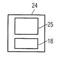
ここで本発明による方法が始まる。本発明によれば、シミュレーションユニット7によって、ポストプロセッサ5によって発生された部分プログラムにおいて、シミュレーション構成、すなわちシミュレーションが行なわれた工作機械の構成が、部分プログラム内に格納される。このようにしてシミュレーションユニット7により、工作機械のシミュレーション構成の使用およびシミュレーション構成をまだ格納していない部分プログラムのもとで、加工プロセスのシミュレーションを行う部分プログラムが作成され、引続いてシミュレーション構成が部分プログラム内に格納される。このようにして作成された部分プログラム24が図3に示されている。部分プログラム24は、このようにして、ポストプロセッサ5からの部分プログラムの命令25とシミュレーション構成18とから構成されている。部分プログラム24は一般に、命令25とシミュレーション構成18とを含むファイルの形で存在する。部分プログラムへのシミュレーション構成18の格納は、例えばファイル内へのシミュレーション構成18の保存によって行なわれる。
Here the method according to the invention begins. According to the present invention, in the partial program generated by the
本発明によれば、工作機械の制御装置9が、工作機械の加工プロセスを開始する前に、工作機械の現在の構成を、例えば工作機械内に組み込まれた画像検出装置11、センサ12および/または工作機械に一体化された測定装置13に基づいて求める。例えばカメラの形で存在することができる画像検出装置11により、例えば工具チャックの瞬時位置(工具チャックデータ)ならびに素材位置(素材データ)を検出することができる。センサ12により、例えば工具交換の工具の装備が検出される。測定装置13により、例えば素材の寸法が検出される。工作機械の現在の構成がこのようにして自動的に求められた後、現在の構成が、部分プログラム内に格納されている工作機械のシミュレーション構成と比較される。現在の構成とシミュレーション構成との不一致時には警報信号Wが発生させられ、例えば操作ユニット14に伝達されて操作ユニット14において操作者に対して可視化される。現在の構成とシミュレーション構成との一致時にのみ、加工プロセスが制御装置9によって開始される。この実施例の枠内において、シミュレーション構成が、シミュレーションユニット7によってコード化されて部分プログラム24内に格納され、制御装置9が、現在の構成をシミュレーション構成と比較する前に、部分プログラム内に格納されているシミュレーション構成18をデコードする。これによって、部分プログラム内に格納されているシミュレーション構成を後に不正操作することを確実に阻止することができる。
According to the invention, before the machine
更に、自動的に求められた現在の構成が、CAMシステム3と、ポストプロセッサ5と、シミュレーションユニット7との少なくとも1つに伝送されるならば有利であり、これが矢印16によって示されている。それにより、CAMシステムにおいて、ポストプロセッサにおいて、そしてシミュレーションにおいて使用される工作機械の構成の手動の検出および調整を省略することができる。
Furthermore, it is advantageous if the automatically determined current configuration is transmitted to at least one of the
工作機械の運転装置は、最も簡単な場合に、シミュレーションユニット7なしに、工作機械を制御するための制御装置9の形だけで構成されていてよい。
In the simplest case, the operating device of the machine tool may be configured only in the form of the
しかし、工作機械の運転装置は、制御装置9と、それから構造的に分離された、例えば事務所に設置されたコンピュータとからなるシステムとして構成されていてもよく、このコンピュータ上でシミュレーションユニット7がシミュレーションプログラムの形で実行される。しかし、更にこの関連で、工作機械の運転装置が制御装置9の形で存在し、シミュレーションユニット7が、例えば制御装置9上で実行されるプログラムの形で、したがって制御装置9に一体化された構成部分の形で存在することも可能である。
However, the machine tool operating device may be configured as a system comprising a
制御装置9は、例えば数値制御装置(NC制御装置)として構成されているとよい。
The
図2において、本発明による方法はフローチャートの形でもう一度概略的に示されている。この時点でもシミュレーション構成を含んでいない部分プログラム19が、シミュレーション構成18の考慮のもとでシミュレーション17の枠内においてテストされ、シミュレーション構成18が格納されている部分プログラム24が作成される。引続いて工作機械の現在の構成26の検出20が行なわれ、その後現在の構成26とシミュレーション構成との比較21が行なわれる。現在の構成がシミュレーション構成と一致しない場合には、警報信号の発生22が行なわれる。現在の構成がシミュレーション構成と一致する場合には、加工プロセスの開始23が行なわれる。
In FIG. 2, the method according to the invention is shown schematically once again in the form of a flow chart. At this time, the
1 CADシステム
2 矢印
3 CAMシステム
4 矢印
5 ポストプロセッサ
6 矢印
7 シミュレーションユニット
8 矢印
9 制御装置
10 断面
11 画像検出装置
12 センサ
13 測定装置
14 操作ユニット
16 矢印
17 シミュレーション
18 シミュレーション構成
19 部分プログラム
20 現在構成の検出
21 比較
22 警報信号の発生
23 加工プロセスの開始
24 部分プログラム
25 部分プログラムの命令
26 工作機械の現在の構成
DESCRIPTION OF SYMBOLS 1 CAD system 2
Claims (9)
シミュレーション構成(18)をまだ格納していない部分プログラム(19)が作成され、
工作機械のシミュレーション構成(18)を用いて、シミュレーション構成(18)をまだ格納していない部分プログラム(19)のもとで、加工プロセスのシミュレーション(17)が行なわれ、引続いてシミュレーション構成(18)をまだ格納していない部分プログラム(19)内にシミュレーション構成(18)が格納されることによって、部分プログラム(24)が作成され、
工作機械の現在の構成(26)が求められ、
現在の構成(26)が、部分プログラム(24)内に格納されている工作機械のシミュレーション構成(18)と比較され、シミュレーション構成(18)はコード化されて部分プログラム(24)内に格納されており、現在の構成(26)とシミュレーション構成(18)とを比較する前にデコードされ、
現在の構成(26)とシミュレーション構成(18)との不一致時に警報信号(W)が発生される工作機械の運転方法。 A machine tool operating method in which a machining process of a machine tool is controlled by a partial program (24) ,
A partial program (19) that has not yet stored the simulation configuration (18) is created,
Using the machine tool simulation configuration (18), a machining process simulation (17) is performed under a partial program (19) for which the simulation configuration (18) has not yet been stored, and subsequently the simulation configuration ( By storing the simulation configuration (18) in the partial program (19) that has not yet stored 18), the partial program (24) is created,
The current configuration (26) of the machine tool is sought,
The current configuration (26) is compared with the machine tool simulation configuration (18) stored in the partial program (24), and the simulation configuration (18) is encoded and stored in the partial program (24). Decoded before comparing the current configuration (26) and the simulation configuration (18),
A method of operating a machine tool in which a warning signal (W) is generated when the current configuration (26) and the simulation configuration (18) do not match.
工作機械のシミュレーション構成(18)を用いて、シミュレーション構成(18)をまだ格納していない部分プログラム(19)のもとで、加工プロセスのシミュレーション(17)が行なわれ、シミュレーション構成(18)をまだ格納していない部分プログラム(19)内にシミュレーション構成(18)が格納されることによって、運転装置(9)により部分プログラム(24)が作成され、
シミュレーション構成(18)はコード化されて部分プログラム(24)内に格納され、現在の構成(26)とシミュレーション構成(18)とを比較する前に運転装置(9)によってデコード可能であり、
運転装置(9)が、工作機械の現在の構成(26)を検出し、現在の構成(26)を、部分プログラム(24)内に格納されている工作機械のシミュレーション構成(18)と比較し、現在の構成(26)とシミュレーション構成(18)との不一致時に警報信号(W)を発生する工作機械の運転装置。 A machine tool operating device (9) for controlling a machining process of a machine tool by a partial program (24),
Using the machine tool simulation configuration (18), a machining process simulation (17) is performed under a partial program (19) that does not yet store the simulation configuration (18). By storing the simulation configuration (18) in the partial program (19) not yet stored, the partial program (24) is created by the operating device (9),
The simulation configuration (18) is encoded and stored in the partial program (24) and can be decoded by the driver (9) before comparing the current configuration (26) with the simulation configuration (18) ,
The operating device (9) detects the current configuration (26) of the machine tool and compares the current configuration (26) with the simulation configuration (18) of the machine tool stored in the partial program (24). A machine tool operating device that generates a warning signal (W) when there is a discrepancy between the current configuration (26) and the simulation configuration (18).
Applications Claiming Priority (2)
| Application Number | Priority Date | Filing Date | Title |
|---|---|---|---|
| EP07021943A EP2058717B1 (en) | 2007-11-12 | 2007-11-12 | Method and device for operating a machine tool |
| EP07021943.1 | 2007-11-12 |
Publications (4)
| Publication Number | Publication Date |
|---|---|
| JP2009123209A JP2009123209A (en) | 2009-06-04 |
| JP2009123209A6 JP2009123209A6 (en) | 2009-08-13 |
| JP2009123209A5 JP2009123209A5 (en) | 2011-11-10 |
| JP5522926B2 true JP5522926B2 (en) | 2014-06-18 |
Family
ID=39113679
Family Applications (1)
| Application Number | Title | Priority Date | Filing Date |
|---|---|---|---|
| JP2008287534A Active JP5522926B2 (en) | 2007-11-12 | 2008-11-10 | Method and apparatus for operating machine tool |
Country Status (3)
| Country | Link |
|---|---|
| US (1) | US8326448B2 (en) |
| EP (1) | EP2058717B1 (en) |
| JP (1) | JP5522926B2 (en) |
Families Citing this family (18)
| Publication number | Priority date | Publication date | Assignee | Title |
|---|---|---|---|---|
| DE102004061579A1 (en) * | 2004-12-21 | 2006-07-06 | Siemens Ag | Module for simulating a sensor signal |
| DE102009037237A1 (en) * | 2009-08-12 | 2011-02-17 | Repower Systems Ag | Method and arrangement for automatic configuration parameter control in wind turbines |
| JP5152434B2 (en) * | 2010-04-27 | 2013-02-27 | 三菱電機株式会社 | Numerical controller |
| JP2012053508A (en) * | 2010-08-31 | 2012-03-15 | Mitsubishi Heavy Ind Ltd | Numerically controlled machine tool |
| EP2839925B1 (en) * | 2012-04-17 | 2020-12-02 | Makino Milling Machine Co., Ltd. | Interference determination method and interference determination device for machine tool |
| JP6066041B2 (en) * | 2012-07-17 | 2017-01-25 | 三菱日立パワーシステムズ株式会社 | Processing support device and processing support system |
| EP3045993A1 (en) * | 2015-01-15 | 2016-07-20 | Siemens Aktiengesellschaft | Manufacturing system with added functionality and method of operation |
| JP2016218550A (en) * | 2015-05-15 | 2016-12-22 | ファナック株式会社 | Numerical control device for confirming fitting state of tool used in machining |
| EP3415781B1 (en) | 2015-06-04 | 2020-04-22 | Meritor Heavy Vehicle Braking Systems (UK) Limited | Guide assembly |
| DE102015213614A1 (en) * | 2015-07-20 | 2017-01-26 | Siemens Aktiengesellschaft | Method for processing workpieces |
| CA2954312C (en) | 2016-01-14 | 2020-08-25 | 2141632 Ontario Inc. | Electronically controlled substrate working apparatus |
| US10401823B2 (en) | 2016-02-04 | 2019-09-03 | Makino Inc. | Real time machining process monitoring utilizing preprocess simulation |
| WO2021058528A1 (en) * | 2019-09-27 | 2021-04-01 | Saint-Gobain Glass France | Automated manufacturing process, and manufacturing system for bending glass panes using an integrated digital image |
| CN112955836A (en) * | 2019-09-27 | 2021-06-11 | 法国圣戈班玻璃厂 | Automated production process and production system for bending glass sheets with integrated digital imaging |
| WO2021058529A1 (en) * | 2019-09-27 | 2021-04-01 | Saint-Gobain Glass France | Automated manufacturing process, and manufacturing system for bending glass panes using an integrated digital image |
| US20230236567A1 (en) | 2020-07-03 | 2023-07-27 | Fanuc Corporation | Post-processor, machining program generation method, cnc machining system, and program for generating machining program |
| EP4105745A1 (en) | 2021-06-14 | 2022-12-21 | Siemens Aktiengesellschaft | Generation and processing of encrypted program instructions using a numerical control device |
| EP4160457A1 (en) | 2021-09-30 | 2023-04-05 | Siemens Aktiengesellschaft | Encoding of program instructions on a numerical control device |
Family Cites Families (59)
| Publication number | Priority date | Publication date | Assignee | Title |
|---|---|---|---|---|
| US4309600A (en) * | 1967-12-15 | 1982-01-05 | Cincinnati Milacron Inc. | Machine tool |
| US4531182A (en) * | 1969-11-24 | 1985-07-23 | Hyatt Gilbert P | Machine control system operating from remote commands |
| US3686639A (en) * | 1969-12-11 | 1972-08-22 | Modicon Corp | Digital computer-industrial controller system and apparatus |
| US3895354A (en) * | 1973-08-31 | 1975-07-15 | Warner Swasey Co | Program editor for machine control |
| JPS59216208A (en) * | 1983-05-23 | 1984-12-06 | Mitsubishi Electric Corp | Numerical control device |
| DE3427127A1 (en) * | 1984-07-23 | 1986-01-23 | Siemens AG, 1000 Berlin und 8000 München | METHOD FOR CONTROLLER OPTIMIZATION FOR DRIVES |
| US4636938A (en) * | 1984-08-31 | 1987-01-13 | Cincinnati Milacron Inc. | Method and apparatus for producing numerical control programs |
| JPS6195407A (en) * | 1984-10-16 | 1986-05-14 | Mitsubishi Electric Corp | Method for reporting status of numerically controlledmachine tool |
| JPS62199338A (en) * | 1986-02-27 | 1987-09-03 | Fanuc Ltd | Automatic prevention device for tool collision |
| JP2612225B2 (en) * | 1993-07-23 | 1997-05-21 | 株式会社東芝 | NC machine tools |
| US5691909A (en) * | 1995-12-29 | 1997-11-25 | Western Atlas | Method of virtual machining to predict the accuracy of part to be made with machine tools |
| US5886897A (en) * | 1996-05-06 | 1999-03-23 | Amada Soft America Inc. | Apparatus and method for managing and distributing design and manufacturing information throughout a sheet metal production facility |
| US5971589A (en) * | 1996-05-06 | 1999-10-26 | Amadasoft America, Inc. | Apparatus and method for managing and distributing design and manufacturing information throughout a sheet metal production facility |
| US5864482A (en) * | 1996-05-06 | 1999-01-26 | Amadasoft America, Inc. | Apparatus and method for managing distributing design and manufacturing information throughout a sheet metal production facility |
| US5822207A (en) * | 1996-05-06 | 1998-10-13 | Amadasoft America, Inc. | Apparatus and method for integrating intelligent manufacturing system with expert sheet metal planning and bending system |
| CA2252754C (en) * | 1996-06-06 | 2005-10-18 | The Boeing Company | Method for improving the accuracy of machines |
| AUPO206596A0 (en) * | 1996-08-30 | 1996-09-26 | Anca Pty Ltd | Tool grinding simulation system |
| JPH10214111A (en) * | 1996-11-28 | 1998-08-11 | Fujitsu Ltd | Data collation method, and data collation device and storage medium therefor |
| US6349237B1 (en) * | 1997-12-23 | 2002-02-19 | The Regents Of The University Of Michigan | Reconfigurable manufacturing system having a production capacity method for designing same and method for changing its production capacity |
| US6477683B1 (en) * | 1999-02-05 | 2002-11-05 | Tensilica, Inc. | Automated processor generation system for designing a configurable processor and method for the same |
| US20030023435A1 (en) * | 2000-07-13 | 2003-01-30 | Josephson Daryl Craig | Interfacing apparatus and methods |
| JP4329248B2 (en) * | 2000-09-05 | 2009-09-09 | 株式会社森精機製作所 | NC machining simulation equipment |
| EP1238740B1 (en) * | 2001-03-05 | 2008-05-14 | Charmilles Technologies S.A. | Process and apparatus for electroerosion milling three-dimensional workpieces |
| US6608282B2 (en) * | 2001-04-12 | 2003-08-19 | W.A. Whitney Co. | Machine tool loading apparatus |
| DE10152765B4 (en) * | 2001-07-13 | 2015-11-12 | Siemens Aktiengesellschaft | A method for electronically providing services to machines via a data communication link |
| US20030045947A1 (en) * | 2001-08-30 | 2003-03-06 | The Boeing Company | System, method and computer program product for controlling the operation of motion devices by directly implementing electronic simulation information |
| DE10144932B4 (en) * | 2001-09-12 | 2014-07-31 | Siemens Aktiengesellschaft | Visualization of workpieces in the simulation of milling processes |
| US7552203B2 (en) * | 2001-10-17 | 2009-06-23 | The Boeing Company | Manufacturing method and software product for optimizing information flow |
| CN1630838B (en) * | 2002-02-07 | 2010-05-26 | 三菱电机株式会社 | Numeric control method and numeric control system |
| KR100478732B1 (en) * | 2002-03-20 | 2005-03-24 | 학교법인 포항공과대학교 | Step-numerical controller |
| US20040102872A1 (en) * | 2002-11-26 | 2004-05-27 | Schick Louis Andrew | Method and tool for power plant operational optimization |
| DE10307261A1 (en) * | 2003-02-20 | 2004-09-09 | Siemens Ag | Programming platform for creating part programs for machine tools or production machines |
| JP3853752B2 (en) * | 2003-04-22 | 2006-12-06 | 三菱電機株式会社 | Simulation device |
| DE10345626A1 (en) * | 2003-09-29 | 2005-05-12 | Heidenhain Gmbh Dr Johannes | Numerical control with machine tool simulator |
| US8417370B2 (en) * | 2003-10-17 | 2013-04-09 | Hexagon Metrology Ab | Apparatus and method for dimensional metrology |
| DE10351781B4 (en) * | 2003-11-06 | 2006-12-07 | Siemens Ag | Computer-aided adaptation method for a user program for a machine tool and objects corresponding thereto |
| DE20321699U1 (en) * | 2003-11-12 | 2009-01-15 | Siemens Aktiengesellschaft | Computer for performing a simulation method for machining a workpiece by a machine tool |
| DE102004013615A1 (en) * | 2004-03-19 | 2005-10-13 | Siemens Ag | Operating method for a machine tool controlled by a control device |
| US7729789B2 (en) * | 2004-05-04 | 2010-06-01 | Fisher-Rosemount Systems, Inc. | Process plant monitoring based on multivariate statistical analysis and on-line process simulation |
| US7331739B2 (en) * | 2004-08-12 | 2008-02-19 | Makino Milling Machine Co., Ltd. | Method for machining workpiece |
| US20060058907A1 (en) * | 2004-09-14 | 2006-03-16 | Ugs Corp. | System, method, and computer program product for machine tool programming |
| DE102004045933A1 (en) * | 2004-09-22 | 2006-03-30 | Siemens Ag | Method for operating an automation device or device for carrying out the method |
| US20060129270A1 (en) * | 2004-12-10 | 2006-06-15 | Gerold Pankl | Processes and systems for creation of machine control for specialty machines requiring manual input |
| DE102005025338B4 (en) * | 2005-05-31 | 2019-03-14 | Siemens Aktiengesellschaft | 08.Method for machining a workpiece |
| DE102005043022A1 (en) * | 2005-09-09 | 2007-03-22 | Siemens Ag | Method and / or device for controlling and / or monitoring a movement in industrial machines |
| DE102005047543A1 (en) * | 2005-09-30 | 2007-04-05 | Siemens Ag | Controller and/or machine behavior simulating method for tool or production machine, involves automatically transferring data over tool or production machine from machine to simulation device using intranet and/or internet |
| US7376480B2 (en) * | 2005-11-09 | 2008-05-20 | The Boeing Company | Multihead composite material application machine programming method and apparatus for manufacturing composite structures |
| US7536235B2 (en) * | 2005-12-22 | 2009-05-19 | The Boeing Company | Multihead composite material application machine post-processor method and apparatus for manufacturing composite structures |
| US7769481B2 (en) * | 2005-12-23 | 2010-08-03 | The Boeing Company | Head assignment system and method |
| US7747421B2 (en) * | 2005-12-23 | 2010-06-29 | The Boeing Company | Head assignment modeling and simulation |
| KR100722504B1 (en) * | 2006-01-18 | 2007-05-29 | 학교법인 포항공과대학교 | The method of non-linear process planning and internet-based step-nc system using the same |
| EP1818763A1 (en) * | 2006-02-08 | 2007-08-15 | Hurco Companies Inc. | Laptop-based machine control simulator |
| DE102006009263A1 (en) * | 2006-02-28 | 2007-09-06 | Siemens Ag | System and method for analyzing the runtime behavior of a control program for a manufacturing process |
| JP2009545040A (en) * | 2006-07-28 | 2009-12-17 | シーメンス アクチエンゲゼルシヤフト | Method and apparatus for compensating for position dependent flexibility in machine tools |
| US8024068B2 (en) * | 2006-08-04 | 2011-09-20 | Hurco Companies, Inc. | Machine tool control system |
| US8725283B2 (en) * | 2006-08-04 | 2014-05-13 | Hurco Companies, Inc. | Generalized kinematics system |
| DE102006043390B4 (en) * | 2006-09-15 | 2010-05-27 | Dmg Electronics Gmbh | Apparatus and method for simulating a process for machining a workpiece on a machine tool |
| US9588511B2 (en) * | 2007-08-03 | 2017-03-07 | Hurco Companies, Inc. | Virtual machine manager |
| JP5139230B2 (en) * | 2008-10-06 | 2013-02-06 | オークマ株式会社 | Collision prevention device in numerical control device |
-
2007
- 2007-11-12 EP EP07021943A patent/EP2058717B1/en active Active
-
2008
- 2008-11-10 JP JP2008287534A patent/JP5522926B2/en active Active
- 2008-11-10 US US12/267,987 patent/US8326448B2/en active Active
Also Published As
| Publication number | Publication date |
|---|---|
| EP2058717B1 (en) | 2011-07-20 |
| JP2009123209A (en) | 2009-06-04 |
| US8326448B2 (en) | 2012-12-04 |
| US20090198366A1 (en) | 2009-08-06 |
| EP2058717A1 (en) | 2009-05-13 |
Similar Documents
| Publication | Publication Date | Title |
|---|---|---|
| JP5522926B2 (en) | Method and apparatus for operating machine tool | |
| JP2009123209A6 (en) | Method and apparatus for operating machine tool | |
| CN102163047B (en) | Robot with learning control function | |
| US9753449B2 (en) | Numerical control device | |
| JP4920785B2 (en) | Numerical control method and apparatus | |
| JP5000543B2 (en) | Machine tool control method and apparatus therefor | |
| US11048215B2 (en) | Tool selecting apparatus and machine learning device | |
| US11048227B2 (en) | Abnormality detection device of machine tool | |
| US20080306620A1 (en) | Method for Machining a Workpiece | |
| US10228681B2 (en) | Method of generating a machining program | |
| US20110257778A1 (en) | Method and device for simulating nc working machine | |
| JP2006293537A (en) | Numerical control apparatus | |
| US9715228B2 (en) | Numerical controller capable of preventing wrong machining after machining condition change | |
| US10133258B2 (en) | Control device for a machine tool | |
| JP2006215740A (en) | Numerical control device | |
| US20160224014A1 (en) | Numerical controller capable of partial correction of machining cycle | |
| US8588957B2 (en) | Cutting tool data verification system and method | |
| JP5287984B2 (en) | Machining simulation method and apparatus, and program for causing computer to execute the method | |
| CN107436589B (en) | Numerical controller having program correction support function for solving alarm | |
| CN109143979B (en) | Machining control method and system of numerical control equipment, readable storage medium and equipment | |
| JP2019506657A (en) | Method and controller for monitoring machine tools | |
| JP2016033705A (en) | Numerical control unit, control method, storage medium | |
| US10007252B2 (en) | Machine tool controller | |
| US20190384262A1 (en) | Numerical controller and misinput detecting method | |
| JP2010231737A (en) | Numerical control device having interference check function |
Legal Events
| Date | Code | Title | Description |
|---|---|---|---|
| A521 | Request for written amendment filed |
Free format text: JAPANESE INTERMEDIATE CODE: A523 Effective date: 20110922 |
|
| A621 | Written request for application examination |
Free format text: JAPANESE INTERMEDIATE CODE: A621 Effective date: 20110922 |
|
| A977 | Report on retrieval |
Free format text: JAPANESE INTERMEDIATE CODE: A971007 Effective date: 20121226 |
|
| A131 | Notification of reasons for refusal |
Free format text: JAPANESE INTERMEDIATE CODE: A131 Effective date: 20130129 |
|
| A521 | Request for written amendment filed |
Free format text: JAPANESE INTERMEDIATE CODE: A523 Effective date: 20130425 |
|
| A02 | Decision of refusal |
Free format text: JAPANESE INTERMEDIATE CODE: A02 Effective date: 20130917 |
|
| A521 | Request for written amendment filed |
Free format text: JAPANESE INTERMEDIATE CODE: A523 Effective date: 20140116 |
|
| A911 | Transfer to examiner for re-examination before appeal (zenchi) |
Free format text: JAPANESE INTERMEDIATE CODE: A911 Effective date: 20140128 |
|
| TRDD | Decision of grant or rejection written | ||
| A01 | Written decision to grant a patent or to grant a registration (utility model) |
Free format text: JAPANESE INTERMEDIATE CODE: A01 Effective date: 20140311 |
|
| A61 | First payment of annual fees (during grant procedure) |
Free format text: JAPANESE INTERMEDIATE CODE: A61 Effective date: 20140408 |
|
| R150 | Certificate of patent or registration of utility model |
Ref document number: 5522926 Country of ref document: JP Free format text: JAPANESE INTERMEDIATE CODE: R150 |
|
| R250 | Receipt of annual fees |
Free format text: JAPANESE INTERMEDIATE CODE: R250 |
|
| R250 | Receipt of annual fees |
Free format text: JAPANESE INTERMEDIATE CODE: R250 |
|
| R250 | Receipt of annual fees |
Free format text: JAPANESE INTERMEDIATE CODE: R250 |
|
| R250 | Receipt of annual fees |
Free format text: JAPANESE INTERMEDIATE CODE: R250 |
|
| R250 | Receipt of annual fees |
Free format text: JAPANESE INTERMEDIATE CODE: R250 |
|
| R250 | Receipt of annual fees |
Free format text: JAPANESE INTERMEDIATE CODE: R250 |
|
| R250 | Receipt of annual fees |
Free format text: JAPANESE INTERMEDIATE CODE: R250 |