JP5499367B2 - System and method for automatic power on and synchronization of a wireless remote console to a central controller to enable remote control of medical devices - Google Patents
System and method for automatic power on and synchronization of a wireless remote console to a central controller to enable remote control of medical devices Download PDFInfo
- Publication number
- JP5499367B2 JP5499367B2 JP2010534016A JP2010534016A JP5499367B2 JP 5499367 B2 JP5499367 B2 JP 5499367B2 JP 2010534016 A JP2010534016 A JP 2010534016A JP 2010534016 A JP2010534016 A JP 2010534016A JP 5499367 B2 JP5499367 B2 JP 5499367B2
- Authority
- JP
- Japan
- Prior art keywords
- remote console
- central controller
- medical device
- console
- wireless
- Prior art date
- Legal status (The legal status is an assumption and is not a legal conclusion. Google has not performed a legal analysis and makes no representation as to the accuracy of the status listed.)
- Active
Links
Images


Classifications
-
- A—HUMAN NECESSITIES
- A61—MEDICAL OR VETERINARY SCIENCE; HYGIENE
- A61B—DIAGNOSIS; SURGERY; IDENTIFICATION
- A61B1/00—Instruments for performing medical examinations of the interior of cavities or tubes of the body by visual or photographical inspection, e.g. endoscopes; Illuminating arrangements therefor
- A61B1/04—Instruments for performing medical examinations of the interior of cavities or tubes of the body by visual or photographical inspection, e.g. endoscopes; Illuminating arrangements therefor combined with photographic or television appliances
- A61B1/045—Control thereof
-
- A—HUMAN NECESSITIES
- A61—MEDICAL OR VETERINARY SCIENCE; HYGIENE
- A61B—DIAGNOSIS; SURGERY; IDENTIFICATION
- A61B1/00—Instruments for performing medical examinations of the interior of cavities or tubes of the body by visual or photographical inspection, e.g. endoscopes; Illuminating arrangements therefor
- A61B1/00002—Operational features of endoscopes
- A61B1/00004—Operational features of endoscopes characterised by electronic signal processing
- A61B1/00006—Operational features of endoscopes characterised by electronic signal processing of control signals
-
- A—HUMAN NECESSITIES
- A61—MEDICAL OR VETERINARY SCIENCE; HYGIENE
- A61B—DIAGNOSIS; SURGERY; IDENTIFICATION
- A61B1/00—Instruments for performing medical examinations of the interior of cavities or tubes of the body by visual or photographical inspection, e.g. endoscopes; Illuminating arrangements therefor
- A61B1/00002—Operational features of endoscopes
- A61B1/00011—Operational features of endoscopes characterised by signal transmission
- A61B1/00016—Operational features of endoscopes characterised by signal transmission using wireless means
-
- A—HUMAN NECESSITIES
- A61—MEDICAL OR VETERINARY SCIENCE; HYGIENE
- A61B—DIAGNOSIS; SURGERY; IDENTIFICATION
- A61B1/00—Instruments for performing medical examinations of the interior of cavities or tubes of the body by visual or photographical inspection, e.g. endoscopes; Illuminating arrangements therefor
- A61B1/00002—Operational features of endoscopes
- A61B1/00059—Operational features of endoscopes provided with identification means for the endoscope
-
- G—PHYSICS
- G06—COMPUTING; CALCULATING OR COUNTING
- G06F—ELECTRIC DIGITAL DATA PROCESSING
- G06F1/00—Details not covered by groups G06F3/00 - G06F13/00 and G06F21/00
- G06F1/26—Power supply means, e.g. regulation thereof
- G06F1/32—Means for saving power
- G06F1/3203—Power management, i.e. event-based initiation of a power-saving mode
- G06F1/3234—Power saving characterised by the action undertaken
- G06F1/325—Power saving in peripheral device
- G06F1/3259—Power saving in cursor control device, e.g. mouse, joystick, trackball
-
- G—PHYSICS
- G06—COMPUTING; CALCULATING OR COUNTING
- G06F—ELECTRIC DIGITAL DATA PROCESSING
- G06F1/00—Details not covered by groups G06F3/00 - G06F13/00 and G06F21/00
- G06F1/26—Power supply means, e.g. regulation thereof
- G06F1/32—Means for saving power
- G06F1/3203—Power management, i.e. event-based initiation of a power-saving mode
- G06F1/3234—Power saving characterised by the action undertaken
- G06F1/3287—Power saving characterised by the action undertaken by switching off individual functional units in the computer system
-
- A—HUMAN NECESSITIES
- A61—MEDICAL OR VETERINARY SCIENCE; HYGIENE
- A61B—DIAGNOSIS; SURGERY; IDENTIFICATION
- A61B1/00—Instruments for performing medical examinations of the interior of cavities or tubes of the body by visual or photographical inspection, e.g. endoscopes; Illuminating arrangements therefor
- A61B1/00002—Operational features of endoscopes
- A61B1/00025—Operational features of endoscopes characterised by power management
- A61B1/00036—Means for power saving, e.g. sleeping mode
-
- A—HUMAN NECESSITIES
- A61—MEDICAL OR VETERINARY SCIENCE; HYGIENE
- A61B—DIAGNOSIS; SURGERY; IDENTIFICATION
- A61B17/00—Surgical instruments, devices or methods, e.g. tourniquets
- A61B2017/00017—Electrical control of surgical instruments
- A61B2017/00199—Electrical control of surgical instruments with a console, e.g. a control panel with a display
-
- A—HUMAN NECESSITIES
- A61—MEDICAL OR VETERINARY SCIENCE; HYGIENE
- A61B—DIAGNOSIS; SURGERY; IDENTIFICATION
- A61B2560/00—Constructional details of operational features of apparatus; Accessories for medical measuring apparatus
- A61B2560/02—Operational features
- A61B2560/0204—Operational features of power management
- A61B2560/0214—Operational features of power management of power generation or supply
-
- G—PHYSICS
- G16—INFORMATION AND COMMUNICATION TECHNOLOGY [ICT] SPECIALLY ADAPTED FOR SPECIFIC APPLICATION FIELDS
- G16H—HEALTHCARE INFORMATICS, i.e. INFORMATION AND COMMUNICATION TECHNOLOGY [ICT] SPECIALLY ADAPTED FOR THE HANDLING OR PROCESSING OF MEDICAL OR HEALTHCARE DATA
- G16H40/00—ICT specially adapted for the management or administration of healthcare resources or facilities; ICT specially adapted for the management or operation of medical equipment or devices
- G16H40/60—ICT specially adapted for the management or administration of healthcare resources or facilities; ICT specially adapted for the management or operation of medical equipment or devices for the operation of medical equipment or devices
- G16H40/63—ICT specially adapted for the management or administration of healthcare resources or facilities; ICT specially adapted for the management or operation of medical equipment or devices for the operation of medical equipment or devices for local operation
-
- H—ELECTRICITY
- H04—ELECTRIC COMMUNICATION TECHNIQUE
- H04L—TRANSMISSION OF DIGITAL INFORMATION, e.g. TELEGRAPHIC COMMUNICATION
- H04L63/00—Network architectures or network communication protocols for network security
- H04L63/08—Network architectures or network communication protocols for network security for authentication of entities
-
- H—ELECTRICITY
- H04—ELECTRIC COMMUNICATION TECHNIQUE
- H04L—TRANSMISSION OF DIGITAL INFORMATION, e.g. TELEGRAPHIC COMMUNICATION
- H04L67/00—Network arrangements or protocols for supporting network services or applications
- H04L67/01—Protocols
- H04L67/12—Protocols specially adapted for proprietary or special-purpose networking environments, e.g. medical networks, sensor networks, networks in vehicles or remote metering networks
-
- Y—GENERAL TAGGING OF NEW TECHNOLOGICAL DEVELOPMENTS; GENERAL TAGGING OF CROSS-SECTIONAL TECHNOLOGIES SPANNING OVER SEVERAL SECTIONS OF THE IPC; TECHNICAL SUBJECTS COVERED BY FORMER USPC CROSS-REFERENCE ART COLLECTIONS [XRACs] AND DIGESTS
- Y02—TECHNOLOGIES OR APPLICATIONS FOR MITIGATION OR ADAPTATION AGAINST CLIMATE CHANGE
- Y02D—CLIMATE CHANGE MITIGATION TECHNOLOGIES IN INFORMATION AND COMMUNICATION TECHNOLOGIES [ICT], I.E. INFORMATION AND COMMUNICATION TECHNOLOGIES AIMING AT THE REDUCTION OF THEIR OWN ENERGY USE
- Y02D10/00—Energy efficient computing, e.g. low power processors, power management or thermal management
Abstract
Description
本発明は、医療装置の遠隔制御を可能にするための、中央制御装置に対する無線遠隔コンソールの自動的電源ON及び同期化のためのシステム及び方法に係り、特に無線リモート制御装置によって1台あるいは複数の医療装置を制御するための装置であって、中央制御装置の近くに配置された無線遠隔コンソールを自動的に電源ONするためのシステム及び方法に関する。 The present invention relates to a system and method for automatic power on and synchronization of a wireless remote console to a central controller to enable remote control of medical devices, and in particular, one or more wireless remote control devices. TECHNICAL FIELD The present invention relates to a system and method for automatically powering on a wireless remote console located near a central control device for controlling a medical device.
内視鏡検査は、身体の内部的特徴を侵襲が少ない状態で視認できるようにする技術である。医療において、内視鏡検査は、侵襲的な外科手術を行う必要なしに、人体の内部的特徴の高品質の画像を得ることを可能にしてくれる。内視鏡検査の基本的なツールは、内視鏡(『スコープ』)であり、視認の対象となる身体に挿入される。一部の内視鏡検査手順には、例えば、胃腸病の医療分野におけると同様の可撓性のある内視鏡の使用が伴う。関節鏡検査や腹腔鏡検査などの他の医療手順では、固い内視鏡が使われる。通常、これらの内視鏡は、その内視鏡を通じて体内に光を送る高強度光源及びビデオ画像データを取得するための電子機器を含んだカメラ・ヘッドに結合されている。このカメラ・ヘッドは、通常、カメラで取得されたビデオ画像を表示するビデオ・モニターに結合されている。 Endoscopy is a technique that allows viewing the internal features of the body in a less invasive state. In medical endoscopy, without the need for invasive surgery, us possible to obtain high-quality images of the human internal features. The basic tool of endoscopy is an endoscope ( "scope"), is inserted into the body to be visible. Some endoscopy procedures involve the use of flexible endoscopes similar to those in the medical field of gastrointestinal diseases, for example. Other medical procedures, such as arthroscopy and laparoscopic examination, use rigid endoscopes. Usually, these endoscopes is coupled to the camera head containing electronic devices for obtaining high strength light source and video image data to send the light to the body through the endoscope. The camera head is typically coupled to a video monitor that displays the video image acquired by the camera.
内視鏡を用いた外科手術においては、視認したり作業したりするために、より多くのスペースをつくりだすための身体の空洞部に加圧ガスを送り込むための吸入器、出血を止めるための電気焼灼器、及び/又は身体組織を切除したり成形したりするための種々の装置など、その他の種々の装置が使われる場合がある。これらの装置は、通常、手術室の床に配置され、外科医によって操作されるフット・ペダル及び/又はスイッチなどによって遠隔的に制御される。足による制御装置は、ON/OFF、速度や強度、ツールの動きの状態、操作モードなどの機能を制御することができる。足による制御装置などを用いることにより、外科医は、ツールを下ろしたり、手を取り替えたり、汚染されている可能性のある表面を手で触ったり、あるいは患者から目を離したりせずに、種々のモードやツールの設定(例えば速度や強度)を調節することができる。 In endoscopic surgery using, for or working or viewing, inhalers for feeding pressurized gas into the cavity of the body to create more space, electricity to stop bleeding Various other devices may be used, such as ablation devices and / or various devices for cutting and shaping body tissue. These devices are usually placed on the floor of the operating room, it is remotely controlled, such as by a foot pedal and / or switch is operated by the surgeon. Control device according legs may control ON / OFF, speed and strength, the movement of the tools of the state, functions such as the operation mode. By using a foot control device, the surgeon does not have to lower the tool, change hands, touch a potentially contaminated surface, or keep an eye on the patient. Mode and tool settings (eg speed and intensity) can be adjusted.
第一世代のフット・ペダル及びその他のタイプの遠隔制御用コンソールは、通常、電気的インパスルの形態のコマンド信号を、制御装置に物理的に接続する伝導回線、あるいはケーブルを通じて中継することによって機能した。 The first generation of foot pedals and other types of remote control console is usually a command signal in the form of electrical Inpasuru functioned by relaying through physically connected to conducting line or cable, to the control device .
技術の進展と共に、これらの遠隔制御装置は、無線化されている。それによって、床上にケーブルを這わせなくても、手術室内のどこにでも、無線遠隔制御用コンソールを配置できるようになった。このような無線遠隔制御用コンソール(以下『遠隔コンソール』と略記)は、通常、中央制御装置と無線で交信する様に構成されている。この中央制御装置は、遠隔で制御される1つあるいは複数の医療装置と交信する。無線交信の信頼性を確保し、さらに、近くの別の無線装置との干渉や偶発的な交信を防ぐために、この遠隔コンソールは、中央制御装置と同期化されている。それによって、中央制御装置は、同期化された遠隔コンソールから発信されたコマンド信号だけを確実に識別することができる。この同期化プロセスは、通常、中央制御装置をプログラミングして、特定の遠隔コンソールから発信されたすべての無線通信だけを識別するようにさせるステップを含んでいる。 With the progress of technology, these remote control devices are wirelessly reduction. This makes it possible to place a wireless remote control console anywhere in the operating room without having to run a cable on the floor. Such wireless remote control console (hereinafter abbreviated as "remote console") is typically configured so as to communicate with the central controller wirelessly. The central controller communicates with one or more medical devices controlled remotely. To ensure the reliability of wireless communication, further, in order to prevent interference and accidental communication with another nearby wireless device, the remote console is a central controller and synchronization. Thereby, the central control apparatus can reliably identify only command signals originating from the synchronized remote console. The synchronization process is usually programmed central control unit, including the step of so as to identify only all wireless communication originating from a particular remote console.
遠隔コンソールを中央制御装置と組み合わせたり同期化させるための1つの方法は、遠隔コンソールの識別コードを手作業で中央制御装置に入力するステップを含んでいる。いくつかのより進んだシステムは、この同期化プロセスを部分的に自動化している。それによって、中央制御装置は、例えば、遠隔コンソールがペアリング状態に設定されている。遠隔コンソールが中央制御装置の近くに配置されると、遠隔コンソールのRFIDタグあるいはバーコードを読み取ることによって、識別コードを取り出すことができるようになっている。 One method for combining and synchronizing the remote console with the central controller includes manually entering the remote console identification code into the central controller. Some of the more advanced system is to automate the synchronization process partially. Thereby, in the central control device, for example, the remote console is set to the pairing state . When the remote console is located near the central controller , the identification code can be retrieved by reading the RFID tag or bar code of the remote console.
ところで、一般の遠隔コンソールは、バッテリー電力の保存をするために、不活性状態が一定期間続いた後に、スイッチ・オフあるいは『休眠』状態に入るように構成されている。その結果、ユーザーが遠隔コンソールを中央制御装置に同期させたい場合に、ユーザーは、遠隔コンソールを『目覚ませる』かONにして、遠隔コンソールが中央制御装置と交信して同期化プロセスを行わせるようにしなければならない。一般的には、何らかの形のユーザーの操作、例えば、遠隔コンソール上の1つの、あるいは一連のボタンを押すなどの操作によってONされる。 However, generally a remote console, in order to save battery power, after the inactive state continues a predetermined period, and is configured to enter the switch-off or "sleep" state. As a result, if the user wants to synchronize the remote console to the central control unit, as the user, the remote console in the "eye rouse" or ON, to perform synchronization process remote console in communication with the central control unit Must be. In general, the user of the operation of some form, for example, is ON by an operation such as pressing one of the remote console, or a series of buttons.
あるいは、遠隔コンソールを、OFFするのではなく、低レベルではあるが、バッテリー電力を消費し続ける『準覚醒』状態に入るようにして、それによって、その遠隔コンソールが同期化プロセスの開始を検出して、その後に自己を完全な『覚醒』状態にするように構成することもできる。しかしながら、この後者の方式では、遠隔コンソールは使われていない状態でもバッテリー電力を消費し続けることになり、それによって、その遠隔コンソールのバッテリーの寿命をかなり減らすことになってしまう。 Alternatively, the remote console, rather than OFF, albeit at a low level, continue to consume battery power as enter a "quasi-awake" state, whereby the remote console detects the start of the synchronization process to, can also then be configured to self-complete "awake" state. However, this latter scheme will continue to consume battery power even when the remote console is not in use, thereby significantly reducing the battery life of the remote console.
従来の遠隔コンソールの安全性は、新しい接続をする前にユーザーが何らかの従来の接続を「壊してしまう」という失敗によっても損なわれる可能性がある。例えば、遠隔コンソールが第1の手術室に配置されている第1の制御装置に同期化され、無線接続されてしまう場合もある。そうすると、ユーザーは、通常、遠隔コンソール上の1つあるいは複数のボタンを押すことによって行われるような遠隔コンソールと第1の中央制御装置間の無線接続を無効化したり、あるいは「ブレーク」したりする操作を行わずに、遠隔コンソールの場所を変更してしまう。第1の手術室の第1の中央制御装置が遠隔コンソールと無線接続されたままであることを知らない第2のユーザーが、遠隔コンソールを第2の手術室に配置されている第2の中央制御装置に同期化させてしまうこともある。その結果、第1の中央制御装置が依然として遠隔コンソールから無線発信されるコマンド信号に応答しているので、第2の手術室内の1つあるいは複数の医療装置を制御するための遠隔コンソールの使用が、第1の手術室に配置されている1つあるいは複数の医療装置の誤った制御を引き起こしてしまう可能性がある。 The safety of conventional remote console could also be impaired users any conventional connection by the failure of "destroy" before a new connection. For example, the remote console may be synchronized with the first control device disposed in the first operating room and wirelessly connected. Then, the user typically or remote console and or disable a wireless connection between the first central controller, or "break" as performed by pressing one or more buttons on the remote console Changing the location of the remote console without any operation. A second central control where a second user who does not know that the first central control unit of the first operating room remains wirelessly connected to the remote console is located in the second operating room. It may be synchronized to the device. As a result, since the response to the command signal by the first central control unit is wirelessly transmitted from the remote console remains a remote console for controlling one or more medical devices in the second operating room Can cause erroneous control of one or more medical devices located in the first operating room.
従って、必要なのは、ユーザーの操作をほとんど、あるいはまったく必要としないで簡単にONされたり『覚醒』状態にされたりすることが可能な遠隔コンソールのシステムである。さらに、新しい無線接続が確立される前に、従来のすべての無線接続を信頼性をもって自動的に停止できる遠隔コンソールのシステムが必要であった。 What is needed, therefore, most of the user's operation, or a remote console system that can be or are in the "awake" state or easily be ON not at all necessary. Furthermore, new before the wireless connection is established, the system of the remote console conventional all wireless connections can automatically stop reliably has Tsu needed der.
本発明は、
少なくとも1つの医療装置を制御するためのシステムにおいて、
少なくとも1つの医療装置と交信してそれを制御するための中央制御装置と、
少なくとも1つのユーザーが操作できる制御装置と、
前記中央制御装置に前記少なくとも1つのユーザーが操作できる制御装置の状態を示す遠隔コンソールコマンド信号を無線で送信するための遠隔コンソールとで構成され、
前記遠隔コンソールが、電源OFFの場合に、前記中央制御装置に対して所定の近接距離まで近づけられると、自動的に電源ONする、
ことを特徴とする。
The present invention
In a system for controlling at least one medical device,
Least a also a central control device for controlling it in communication with one of the medical device,
A control device at least one user can interact,
A remote console for wirelessly transmitting a remote console command signal indicating a status of the control device operable by the at least one user to the central control device;
Said remote console, in the event of a power OFF, when brought close to a predetermined close distance to the central controller, automatically power ON,
It is characterized by that.
本発明は、一台の遠隔コンソールを用いることで、外科医あるいはその他のユーザーが、内視鏡検査手順中に1台あるいは複数の医療装置を制御することができる。 The present invention, by using a single remote console can be surgeon or other user to control the one or more medical devices during endoscopic procedures.
本発明は、一台の遠隔コンソールを用いることで、外科医あるいはその他のユーザーが、内視鏡検査手順中に1台あるいは複数の医療装置を制御する目的を、遠隔コンソールは、電源OFFの場合に、中央制御装置に対して所定の近接距離まで近づけられると、自動的に電源ONすることで実現するものである。 The present invention uses a single remote console to allow a surgeon or other user to control one or more medical devices during an endoscopic procedure when the remote console is turned off . This is realized by automatically turning on the power when the central control device is brought close to a predetermined proximity distance.
以下にさらに詳細に示すように、本発明による一台の無線遠隔コンソール(以下においては単に『遠隔コンソール』と略記)を用いることで、外科医あるいはその他のユーザーは内視鏡検査手順中に1台あるいは複数の医療装置を制御することができる。この遠隔コンソールは、1つあるいは複数の医療装置を制御するためにユーザーの手や足で操作できるように設計された1つあるいは複数の制御装置で構成することができる。
As shown in more detail below, by using a single wireless remote console according to the present invention (substantially SL simply as "remote console" in below), the surgeon or other user during
説明目的のために、1つあるいは複数のフット・ペダル及び/又は複数の装置が接続されている場合であれば、その装置の選択を可能にする選択スイッチを含む1つ以上の装置へのフット・スイッチを含む足で操作される無線方式の遠隔コンソールの例を考えてみよう。足で操作する制御装置の作動に応じて、遠隔コンソールが中央制御装置に無線で信号を送り、これによって、中央制御装置は、制御対象の装置を選択して、その装置を制御する。この足による遠隔コンソールは、ハウジング内に密封されていて、接続架台に置かれると誘導的に充電される充電可能なバッテリーを含んでいてもよい。この中央制御装置と接続架台とは、別個の装置であってもよいし、単一のハウジング内で一体化されていてもよい。 For illustrative purposes, one or in the case where a plurality of foot pedal and / or a plurality of devices are connected, a foot to one or more devices including a selection switch to allow the selection of the device • Consider an example of a wireless remote console operated with a foot including a switch. Depending on the operation of the control device operated by the foot, the remote console sends a signal by radio to the central control unit, whereby, the central controller selects a device control object for controlling the device. Remote console by the foot, have been sealed in the housing may include a rechargeable battery inductively charged and placed in the docking station. And the central control unit and the docking station may be a separate device, it may be integrated within a single housing.
I.無線遠隔コンソールと中央制御装置
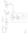
図1は、無線遠隔制御用コンソールの1例を示している。この例では、遠隔コンソール14は、本発明による足で制御される無線方式の無線遠隔制御システムによって示されている。この無線遠隔制御システムは、カメラ制御装置(CCU)を含む第1の装置24Aに接続された内視鏡カメラ21を含んでいる。第1の装置24Aには、内視鏡カメラ21で撮影された画像を表示するためのビデオ・モニター22が接続されている。このシステムは、多数の異なった支援装置24B、24Cなどを含んでおり、それらの中には手術器具(吸入器、電気焼灼器、無線周波数発生装置、あるいはカッター/シェーバー器具など)から手術や臨床環境で用いられるその他の装置(例えば、ビデオ捕捉装置、手術台用照明及び室内照明など)を含んでいる。それらの装置にもよるが、1台あるいは複数の医療装置としての装置24は、第1の装置24Aと支援装置24Bの場合のように、共通の有線通信媒体25によって相互に結合されている場合もある。有線通信媒体25とは、例えば、IEEE標準1394バックプレーン接続、イーサーネット接続、あるいは、その他の同様の能力を有する通信媒体などである。
I. Wireless Remote Console and Central Controller FIG. 1 shows an example of a wireless remote control console . In this example, the
図1に示すように、中央制御装置(受信ユニット)12には、直接かあるいは有線通信媒体25を介して、それぞれの医療装置が接続されている。図1で無線フット制御装置10として示されている遠隔コンソール14は、中央制御装置12と共同して、その中央制御装置12に接続されているすべての装置24を制御する。具体的には、この例では、遠隔コンソール14は、種々の足で操作するペダル、スイッチ及び/又はその他の足操作型制御装置を含んでおり、これらは、ユーザーによって起動されると、無線で制御信号を中央制御装置12に発信するようになっている。遠隔コンソール14から受信された制御信号に応じて、この中央制御装置12は、現在選択されている種々の装置24のうちの1つと交信する。この交信は、第1の装置24Aあるいは支援装置24Bの場合に、有線通信媒体25を通じて、あるいは、支援装置24Cの場合のように、中央制御装置12に対する(アナログかデジタルかいずれかの方式で)直接接続媒体26によって行われる。この直接接続媒体26は、支援装置24Cに固有の遠隔コンソール14の入力を模倣したものであってよい。さらに、1つか複数の被制御装置としての装置24は、無線リンクのみを通じて中央制御装置12と交信することも可能である。
As shown in FIG. 1 , each medical device is connected to the central control device (reception unit) 12 directly or via a
遠隔コンソール14は、無線方式であるから、それ独自の電源を必要としている。1つの実施の形態によれば、この電源は、1つあるいは複数の取替え可能なアルカリ電池であってもよい。他の実施の形態では、この電源は、1つ又は複数の、充電のために遠隔コンソール14から取り出すことができる充電可能なバッテリーを含んでいる。あるいはまた、この充電可能な1つまたは複数のバッテリーを、遠隔コンソール14のハウジング内に密封することも可能である。こうした実施の形態においては、上記の遠隔コンソール14のハウジングは、プラスチック、あるいは、プラスチックと同様の軽量で耐久性が高く、洗浄が可能な素材で形成あるいは成形することができる。こうした方式が望ましいのは、とりわけ、通常、ある種の手術手順中にかなりの量の水及び/又はその他の液体が手術室の床の上にこぼれ落ちるからである。従って、この手術室の環境に対して直接露出される電源コンタクトを必要としないので、こうした密封方式の遠隔コンソール14のハウジングが好適である。さらに、充電可能な内部バッテリーを用いると、手術室で必要とされる電気ケーブルの数も減少する。
The
内部のバッテリーを充電するために、接続架台16を設けることができる。遠隔コンソール14は、接続架台16上に置かれる。そこで、バッテリーは、電磁誘導などの手段で充電される。接続架台16は、遠隔コンソール14が使われていない場合の便利な支持台としても役に立つ。
A connection stand 16 can be provided to charge the internal battery. The
図2の例では、本発明で用いることが出来る1つの可能なタイプの遠隔コンソール14の外観が示されている。具体的に、図2は、比較的軽量で、手術室スタッフ(ユーザー)がコンソール14を持ち上げて運ぶのに便利なハンドル32を含む足で制御される遠隔コンソール14を示している。図2に示されているように、遠隔コンソール14は、ユーザーが制御できる少なくとも1つの制御装置を構成する左右のペダル36Aと36B、そして、3つの足で操作するスイッチ、つまり左側スイッチ34A、中央スイッチ34B、そして右側スイッチ34Cを含んでいる。他の実施の形態では、遠隔コンソール14は、ペダル、スイッチ及び/又は制御装置の組み合わせが異なっている場合もある。スイッチ34は、例えば、単純な押しボタン式スイッチで、例えば、種々の装置24の異なった操作モードを選択するために用いられる。左右のペダル36Aと36Bは、装置24の速度や強度及び/又はその他の種々の設定を制御するために用いられるような、電位差計タイプの簡単な(ずれ可変方式の)足で制御する制御装置などである。
In the example of FIG. 2, the appearance of one possible type of
以下の詳細な説明で、遠隔コンソール14について触れる場合は、常に、図2に示されている例のような足で制御される遠隔コンソール14を想定している。しかしながら、上述したように、本発明の無線遠隔制御システムは、無線の遠隔コンソール14の1つのタイプ、あるいは設計に限定されるものではなく、両足で操作するもの、あるいは、手で操作するコンソールなど、実質上どんなタイプ及び設計に合わせてでも構成することができる。
In the following detailed description, when touching the
いくつかの実施の形態では、図2に示す遠隔コンソール14は、図1に示されている接続された装置24のいずれでも制御することはできるが、一時に制御できるのは、1つの装置だけである。こうした実施の形態では、スイッチ34の1つは、ユーザーが制御する装置24を選択できるようにするための選択スイッチとして用いられる。その他の制御装置のそれぞれの機能は、現在制御の対象として選択されている特定の装置24に対応して変更することができる。この選択は、直接あるいは通信媒体を通じてなり、中央制御装置12に接続されている異なった装置24間で切り替えるために繰り返し用いられる指定された選択スイッチを単に押すだけで行うことができる。
In some embodiments, the
他の実施の形態で、遠隔コンソール14は、2台以上の装置を同時に制御することができる。例えば、2つあるいはそれ以上の個別のスイッチ及び/又はペダルを用いて、2台以上の個別の装置24を同時に制御することができる。あるいはまた、遠隔コンソール14上の同じ制御を、中央制御装置12に接続された2台以上の装置24を制御するために用いることができる。
In another embodiment, the
この中央制御装置12は、どの装置が有線通信媒体25に対して、あるいは直接接続媒体26によって存在しているか、あるいは接続されているかを検出する。従って、遠隔コンソール14は、どの装置が現在選択されているかについての知識をもっている必要はない。というのは、そうした知識は、中央制御装置12内に完全に保持されているからである。遠隔コンソール14は、単に一般的な制御信号を送るだけである。中央制御装置12は、遠隔コンソール14からの制御信号を受信して、現在選択されている装置に合った形式のプロトコルを有する他の制御信号(コマンド信号)とに置き換えて制御を行う。いくつかの実施の形態では、中央制御装置12は、複数の遠隔コンソール14からの入力を同時に受信して、対応する制御信号を、複数の遠隔コンソール14が同じ装置を制御しているのか、あるいは、複数の装置を制御しているのかに応じて、1台か複数の装置に対応する制御信号を出力することができる。
The
図3には、本発明の1つの例示的な実施の形態による無線遠隔コンソール40の構成要素を示している。図3に示されているように、無線遠隔コンソール40は、通常のプログラム可能なマイクロコントローラ42を含んでいる。このマイクロコントローラ42は、比較的短距離の無線周波数のRF送信装置48及びRF受信装置49に結合している。RF送信装置48及びRF受信装置49は、例えば、2.4GHz ISM帯域内で作動するサイプラスWUSBチップ・セットなどの単一送信装置などに、結合一体化することができる。他の実施の形態で、無線遠隔コンソール40は、900MHz RF、ブルートゥース(Bluetooth(登録商標))、802.11a/b/g、ウルトラ広帯域(UWB)及びジグビー(Zigbee(登録商標))、あるいは、赤外線(IR)あるいはレーザーなどの非RF準拠プロトコルを含むその他の無線プロトコルを用いて作動する他の送信装置の構成を用いることもできる。
FIG. 3 shows the components of the wireless
無線遠隔コンソール40には、さらに少なくとも1つの充電可能なバッテリー50が含まれている。また、無線遠隔コンソール40内に含まれているか、あるいは無線遠隔コンソール40の外面に固定的に取り付けられている無線周波数識別(RFID)チップ、あるいはRFIDタグ52も存在している。無線遠隔コンソール40の内部構成部品(つまり、スイッチ類とペダルを除く他の構成部品)は、無線遠隔コンソール40のハウジング内に完全に密封されており、それによって、手術室環境からそれらの構成部品の損傷を護り、電気的ショックやスパークなどの危険性を少なくしている。
The wireless
マイクロコントローラ42は、例えば、標準RS−232インターフェースを通じて、RF送信装置48及びRF受信装置49と交信することができる。RF送信装置48は、ユーザーが足で操作する制御装置(スイッチ44A、44B、44C及びペダル46A及び46B)に適用されるユーザーの入力に応じて、マイクロコントローラ42の制御下で、中央制御装置12に制御信号を送信する。
The
無線遠隔コンソール40内のマイクロコントローラ42には、固有の識別(ID)コードが与えられている。RF送信装置48に送る信号内にそのIDコードを組み込むことによって、無線遠隔コンソール40によって発信されるすべてのコマンド信号をマイクロコートローラ42が独自に識別できるようにしている。このマイクロコントローラ42のIDコードもRFIDタグ52内のメモリーに保存され、それによって、中央制御装置12が無線方式でRFIDタグ52を読み出すことで、無線遠隔コンソール40のそれぞれの同一性を判定できるようにしている。従って、マイクロコントローラ42は、固有の識別コードでプログラム可能な識別装置として機能する。
The
バッテリー50からマイクロコントローラ42への電流の流れを切断することで、無線遠隔コンソール40の電源をON/OFFすることができる起動回路(コイル・スイッチング回路)54は、無線遠隔コンソール40に含まれている。以下に詳細に述べるように、この起動回路54は「閉じられた」状態で配置されている。それによって、その起動回路54が特定の周波数の電磁場に曝された場合に、バッテリー50がマイクロコントローラ42に電源を送ることができるようにしている。
An activation circuit ( coil switching circuit ) 54 that can turn on / off the power of the wireless
図4は、本発明の1つの実施の形態による中央制御装置60の構成図である。図4に示されているように、この中央制御装置60は、プログラム可能なマイクロコントローラ62、無線受信装置であるRF受信装置66及び無線送信装置であるRF送信装置68(あるいは、組み合わせ型送受信装置)、電源供給装置70、そして1つあるいは複数の出力インジケータ64を含んでいる。マイクロコントローラ62は、中央制御装置60全体の作動を制御する。他の実施の形態で、マイクロコントローラ62は、プログラム可能な汎用あるいは専用マイクロプロセッサ、ASICなどの同じ役割を行うことができる1つあるいは他の形態の制御装置に置き換えられる場合もある。RF受信装置66は、図3に関連して上述したように、無線遠隔コンソール40から発信された制御信号を受信する。RF送信装置68は、中央制御装置60からの信号を無線遠隔コンソール40に送る。マイクロコントローラ62は、例えば、標準RS−232インターフェースなどを含むいろいろな手段を介して、RF受信装置66及びRF送信装置68と交信することができる。電源装置76は、利用可能ないずれかの外部電源から供給される電源に基づいて中央制御装置60のための調整された電源を提供する。
FIG. 4 is a block diagram of the
中央制御装置60内には、比較的弱い電磁場を発生する無線周波数識別読取装置であるRFID読取装置74も含まれている。RFIDタグ52がRFID読取装置74に近づけられると、このRFIDタグ52は、電磁エネルギーをピックアップして、RFID読取装置74と交信を開始する。より具体的に言うと、RFIDタグ52が近づけられると、RFID読取装置74によって発生される電磁場が所定の方法で独自に調節され始める。このRFIDタグ52がIDコードなどの情報をRFID読取装置74に交信するのは、こうした電磁場の調節によって行われるからである。
Also included in the
IDコードなどの通信情報に加えて、RFID読取装置74によって発生される電磁場は、無線遠隔コンソール40を電源ONさせるための起動メカニズムとしても用いることができる。以下に詳細に述べるように、図3に示されているような無線遠隔コンソール40は、起動回路54が中央制御装置60のRFID読取装置74によって発生された電磁場の中に持ち込まれると「目覚める」、あるいはONするように構成することができる。
In addition to communication information such as an ID code, the electromagnetic field generated by the
中央制御装置60は、どの装置24(図1参照)が現在選択されているかを示す情報を含めて、システムのユーザーに種々の情報を提供するために用いられる1つあるいは複数の出力インジケータ64も含んでいる。この出力インジケータ64は、例えば、1つあるいは複数の発光ダイオード(LED)、液晶表示装置(LCD)、オーディオ・スピーカーなどを含んでいる場合もある。
The
装置24のうちのどれが現在選択されているのかに応じて、マイクロコントローラ62は、RF受信装置66が受信した制御信号を用いて、有線通信媒体25上の特定の装置24に向けられたコマンド信号及び/又はその他の制御信号を発生する。このマイクロコントローラ62は、現在選択されている装置24に適したフォーマット及び/又はプロトコルでと結合するコマンド信号あるいはその他の制御信号を発生するようにプログラムされている。マイクロコントローラ62は、ネットワーク・アダプタ70に、これらの発生されたコマンド信号を有線通信媒体25に発信させる。
Depending on which of the devices 24 is currently selected, the
このネットワーク・アダプタ70は、例えば、標準IEEE準拠1394アダプタであってもよい。また、有線通信媒体25は、例えば、IEEE1394バックプレーンである。この場合、中央制御装置60は、バックプレーンに接続されているその他の装置を識別するために、標準IEEE1394プロトコルを用いることができる。さに別の実施の形態では、中央制御装置60は、例えば、アサイニー(Assignee)社の統合装置ネットワーク(SIGNE)制御システム及び統合パフォーマンス・システム(TPS)、そしてアサイニー(Assignee)社の無線周波数アブレーション・システム(SERFASTM)などの装置のために設計された接続などを採用することも可能である。
This
いくつかの実施の形態では、、中央制御装置60は、また(あるいは代わりに)、上述の図1に示したように、被制御装置である装置24に対する1つあるいは複数の『直接』(つまりネットワークを通さない)接続を持つこともできる。こうした実施の形態では、中央制御装置60は、マイクロコントローラ62をその直接接続媒体26に結合させる通信アダプタ72を含んでいる。いくつかの例では、直接接続媒体26は、中央制御装置60と装置24との間の接続としてインプリメントされて、他の装置やアダプタはそれらの間に結合されていない。別の例では、直接接続媒体26は、中央制御装置60に対するネットワーク接続をエミュレートする個別の外部アダプタ(『ドングル』)を介してその中央制御装置60を装置24に接続することで、インプリメントすることも可能である。
In some embodiments ,, the
II.起動回路(コイル・スイッチング回路)
上述したように、図3の無線遠隔コンソール40は、中央制御装置60内に含まれているRFID読取装置74によって発生された電磁場に露出されるように、中央制御装置60に近づけられると自動的に「目覚める」、あるいはONするように構成されている。特定の電磁場に露出されると、無線遠隔コンソール40が自動的にONされるこの方式は、無線遠隔コンソール40の部品である起動回路54が担当している。
II. Starting circuit (coil switching circuit)
As described above, wireless
図5は、本発明の1つの実施の形態による起動回路54の回路図である。図5に示すように、起動回路54は、無線遠隔コンソール40が中央制御装置60に近づけられるとRFID読取装置74によって発生される電磁場を検出するためのコイル56を含んでいる。なお、コイル56(以下では『第二次コイル56』と表記)は、RFIDタグ52などの従来のRFIDタグ内に含まれているコイル、あるいはアンテナ(以下では『一次コイル』と表記)とは切り離されている。起動回路54には、コンデンサC1及びC2、二重ダイオード直列体DN1及びDN2、レジスタR1、R2及びR3と、トランジスタT1が含まれている。
FIG. 5 is a circuit diagram of the
二次コイル56は、通常、RFID読取装置74によって発生される電磁場の周波数に対応するインダクタンスを有するように構成、あるいは「巻かれて」いる。その結果、二次コイル56は、RFID読取装置74によって発生される電磁場を検出することができ、そして、その後に、無線遠隔コンソール40をON、あるいは「目覚めさせ」て活性状態に入る。より具体的には、RFID読取装置74によって発生された電磁場は、無線遠隔コンソール40が中央制御装置60に近い位置にあると、二次コイル56内に電流を誘発させる。誘発された電流は、コンデンサC1を充電する。コンデンサC1を通じての電位差が電流を発生させ、この電流が二重ダイオード直列体D1及びD2に指示されて抵抗器R1と、さらに、コンデンサC2、ダイオードD2に抵抗器R2で構成される三つの並列構成部品とを通じて流れる。これが、作動状態を切り換えて、無線遠隔コンソール40の活性化及び無線遠隔コンソール40と中央制御装置60との間の無線接続を、開始させる。
The
III.無線遠隔制御システムの一般的操作
前に検討した本発明の1つの実施の形態によれば、無線遠隔コンソール40と中央制御装置60との間の同期は、無線周波数識別(RFID)によって行われる。具体的には、製造工程で、各無線遠隔コンソール40内に含まれる各マイクロコントローラ42に割り当てられる固有のIDコードが読み取られ、あるいは取得される。この固有のIDコードは、次に、RFIDチップ、あるいはRFIDタグ52に書き込まれる。この新たに書き込まれたRFIDタグ52は、次に、そのIDコードが最初に得られた無線遠隔コンソール40上に、貼付あるいは取り付けられる。
III. According to one embodiment of the present invention previously discussed general operation of the wireless remote control system, the synchronization between the wireless
同期して無線遠隔コンソール40と中央制御装置60との間の無線接続を確立するために、ユーザーは、「睡眠状態の」あるいは電源OFFの無線遠隔コンソール40を持ち、その持った無線遠隔コンソール40を中央制御装置60の隣に配置する。より具体的には、RFIDタグ52を含む無線遠隔コンソール40のエリアは、中央制御装置60のRFID読取装置74と位置に揃えられる。次に、無線遠隔コンソール40が中央制御装置60に近づけられ(例えば、数インチの距離)、それによって、起動回路54の二次コイル56がRFID読取装置74によって発信される電磁場内に配置される。
To establish a wireless connection between the wireless
無線遠隔コンソール40を中央制御装置60に近づけると、二次コイル56がRFID読取装置74によって発信される電磁場内に置かれる。これによって、一般的には、RFID読取装置74によって発生される電磁場の周波数に対応するインダクタンスを持つ様に構成されている二次コイル56によって起動回路54内に電流が発生する。起動回路54内に誘発される電流の量は、トランジスタT1を起動させるにのに十分な量であり、それがマイクロコントローラ42の電源ONと無線遠隔コンソール40の「覚醒」とをもたらす。
When brought close to the wireless
無線遠隔コンソール40を中央制御装置60に近づけると、RFIDタグ52もRFID読取装置74によって発信される電磁場内に置かれる。起動回路54の場合と同様に、電流がRFIDタグ52内にも誘発され、RFIDタグ52によって第2の電磁場が発生される。RFID読取装置74によって発生される第1の電磁場と比較して、RFIDタグ52によって発生される第2の電磁場は、RFIDタグ52のメモリー内に記憶されている固有のIDコードを示すと同時に、無線遠隔コンソール40のマイクロコントローラ42のIDコードを示す信号を含むように調節される。RFID読取装置74は、RFIDタグ52によって発生される第2の調節された電磁場を検出する。それによって、中央制御装置60は、無線遠隔コンソール40が中央制御装置60に近づけられると、無線遠隔コンソール40が無線で識別できるようにしている。
When the wireless
従って、無線遠隔コンソール40を中央制御装置60に近づけるという行為は、無線遠隔コンソール40を、自動的に「目覚めさせる」、あるいは電源ONにすることと、中央制御装置60による無線遠隔コンソール40の無線による識別という2つの初期動作をもたらす。無線遠隔コンソール40が識別されると、中央制御装置60は、『ペアリング』プロセスを開始する。それによって、無線遠隔コンソール40と中央制御装置60とが同期化されて、それらの間の無線接続が確立される。その後の『ペアリング』プロセスについては、「確実な無線接続による医療装置の遠隔制御を可能にするために無線遠隔制御装置を中央制御装置に同期化させるための装置及び方法」と題する米国特許公報No.US2006−0116667を参照されたい。この特許公報の開示内容全体は、本明細書に組み入れられるものとする。
Thus, the act of approximating the wireless
IV.起動回路(コイル・スイッチング回路)を含んでいる無線遠隔制御システムの利点
上に述べたいくつかの実施の形態による医療装置遠隔制御システムは、従来の制御装置と比較していくつかの利点を有している。図5に示されているような起動回路54を用いることで、無線遠隔コンソール40が自動的に電源ONして中央制御装置60との無線接続を開始するように構成することができる。電源をONして無線同期化手順を開始するために、ユーザーに求められる唯一の行為は、無線遠隔コンソール40を中央制御装置60に一時的に近づけることである。対称的に、従来の遠隔制御システムでは、遠隔制御装置が電源ONのまま「半覚醒」状態に留まっていることとが必要になり、そのことでバッテリー電源を消費してしまうか、あるいはユーザーが無線接続を開始する前に手作業で遠隔制御装置を電源ONすることが必要になる。
IV. Medical device remote control system according to some embodiments described on the advantages of a wireless remote control system boot includes a circuit (coil switching circuit), have a number of advantages as compared with the conventional control system doing. By using the
消費者向け製品とか家庭環境で用いられているような従来の遠隔制御システムとは違って、上に述べた実施の形態によるシステムは、無線遠隔コンソール40を電源ONするための特定のコマンド、あるいはコード化された無線信号の受信確認信号を発生しなくてもよいという利点も有している。その代わりに、無線遠隔コンソール40は、単に1つあるいは複数の所定の周波数を有する電磁波の存在に応じて自動的に電源ONされる。従って、無線遠隔コンソール40は、特定の起動あるいは電源ONコマンドを認識するようにプログラムされる必要はない。
Unlike conventional remote control systems such as those used in consumer products or in the home environment, the system according to the above-described embodiment can be configured with a specific command for powering on the wireless
本願で開示されている医療用遠隔制御システムは、手術室環境に直接露出される無線遠隔コンソール40のハウジング上の電気的コンタクトを必要としない。これによって、密封されていて洗浄・消毒が可能な無線遠隔コンソール40のハウジングの提供が可能になる。さらに、上に述べた実施の形態による無線遠隔コンソール40がRFIDタグ52と内部回路との間の電気的接続を必要としていないので、無線遠隔コンソール40は、電磁場の存在に応答して自動的に電源ONすることができる。無線遠隔コンソール40のハウジングに取り付けたり、必要があれば、取り外したりすることができる電気的に隔離されたRFIDタグ52を用いることで、製造も保守も容易な無線遠隔コンソール40の提供が可能になる。
The medical remote control system disclosed herein does not require electrical contact on the housing of the wireless
さらに別の実施の形態によれば、起動回路54は、無線遠隔コンソール40と中央制御装置60との間のそれまでのペアリングを自動的に終了させると同時に、無線遠隔コンソール40を自動的に電源ONするように構成することができる。その結果、ユーザーがそれまでのペアリングを終了させることに失敗して、無線遠隔コンソール40を第2の中央制御装置60とペアリングさせる前に第1の中央制御装置との既存の無線接続を打ち切ることが出来ない場合にも、遠隔制御システムの安全性は損なわれない。
According to yet another embodiment, the
V.追加的な実施の形態
本発明のさらに別の実施の形態によれば、遠隔制御装置は、図5に示されているような起動回路54を含んでおらず、その代わりに電場の存在を検出する読み取りスイッチ、あるいはホール効果センサーに基づく回路を含んでいる。前に述べた実施の形態の場合と同様に、無線遠隔コンソール40は、中央制御装置60に近づけられると自動的に電源ONして無線接続を開始するように構成されている。
V. According to yet another embodiment of the additional embodiment the present invention, the remote control device does not include the start-up
別の実施の形態によれば、このシステムは、遠隔装置を自動的に電源ONするための光学的、音響的、及び反射赤外線感知技術を用いた遠隔コンソールを含んでいる。 According to another embodiment, the system optical for automatically power ON the remote device includes a remote console using acoustic, and a reflective infrared sensor technology.
例示的な実施の形態を参照して本発明について上に述べたが、本発明はこれらの実施の形態に限定されるものではなく、添付請求項の精神と範囲内での修正・変更は可能である。従って、仕様や図面は厳密なものではなく、例として示すものである。 Although the present invention has been described above with reference to exemplary embodiments, the present invention is not limited to these embodiments, and modifications and changes can be made within the spirit and scope of the appended claims. It is. Accordingly, the specifications and drawings are not strict and are provided as examples.
この発明に係るシステムは、各種分野で用いることが可能である。 The system according to the present invention can be used in various fields.
12 60 中央制御装置
14 40 遠隔コンソール
21 内視鏡カメラ
22 ビデオ・モニター
24A 第1の装置(医療装置)
24B、24C 支援装置(医療装置)
25 有線通信媒体
34A、34B、34C スイッチ(ユーザーが操作できる制御装置)
36A、36B ペダル(ユーザーが操作できる制御装置)
42 62 マイクロコントローラ(識別装置)
44A、44B、44C スイッチ(ユーザーが操作できる制御装置)
46A、46B ペダル(ユーザーが操作できる制御装置)
48 68 RF送信装置
49 66 RF受信装置
52 RFIDタグ
54 起動回路
74 RFID読取装置(識別読取装置)
1 2 60 Central controller
14 40 remote console
21 Endoscopic camera
22 Video monitor
24A First device (medical device)
24B, 24C Support device (medical device)
25 wired communication media
34A, 34B, 34C switch (control device that can be operated by the user)
36A, 36B pedal (control device that can be operated by the user)
42 62 Microcontroller (identification device)
44A, 44B, 44C switch (control device that can be operated by the user)
46A, 46B Pedal (control device that can be operated by the user)
48 68 RF transmitter
49 66 RF receiver
52 RFID tags
54 Start-up circuit
74 RFID reader (identification reader)
Claims (17)
少なくとも1つの医療装置と交信してこの交信した医療装置を制御するための中央制御装置と、
ユーザーが操作できる少なくとも1つの制御装置と、
前記中央制御装置に前記少なくとも1つのユーザーが操作できる制御装置の状態を示す遠隔コンソールコマンド信号を無線で送信するための遠隔コンソールとで構成され、
前記遠隔コンソールは、電源OFFの場合に、前記中央制御装置に対して所定の近接距離まで近づけられると、自動的に電源ONする、
ことを特徴とする医療装置の遠隔制御を可能にするための、中央制御装置に対する無線遠隔コンソールの自動的電源ON及び同期化のためのシステム。 In a system for controlling at least one medical device,
A central controller for communicating with the at least one medical device and controlling the communicated medical device;
At least one control device operable by the user;
A remote console for wirelessly transmitting a remote console command signal indicating a status of the control device operable by the at least one user to the central control device;
When the remote console is brought to a predetermined proximity distance to the central control device when the power is off, the remote console is automatically turned on.
A system for automatic power on and synchronization of a wireless remote console to a central controller to enable remote control of a medical device.
前記中央制御装置と組み合わされ、前記識別装置が所定の距離以内に近づくと前記識別装置内にプログラムされている識別コードを無線で取り出す識別読取装置とで構成される、
ことを特徴とする請求項1に記載の医療装置の遠隔制御を可能にするための、中央制御装置に対する無線遠隔コンソールの自動的電源ON及び同期化のためのシステム。 An identification device combined with the remote console and programmable with an identification code unique to the remote console;
In combination with the central control unit, the identification device is configured to include an identification reading device that wirelessly retrieves an identification code programmed in the identification device when the identification device approaches within a predetermined distance.
A system for automatic power on and synchronization of a wireless remote console to a central controller for enabling remote control of a medical device according to claim 1.
ことを特徴とする請求項2に記載の医療装置の遠隔制御を可能にするための、中央制御装置に対する無線遠隔コンソールの自動的電源ON及び同期化のためのシステム。 The identification device is composed of a radio frequency identification device (RFID),
A system for automatic power on and synchronization of a wireless remote console to a central controller to enable remote control of a medical device according to claim 2.
ことを特徴とする請求項2に記載の医療装置の遠隔制御を可能にするための、中央制御装置に対する無線遠隔コンソールの自動的電源ON及び同期化のためのシステム。 In combination with the remote console, including a start-up circuit that automatically powers on the remote console when a current flows through the electromagnetic field generated by the identification reader.
A system for automatic power on and synchronization of a wireless remote console to a central controller to enable remote control of a medical device according to claim 2.
ことを特徴とする請求項3に記載の医療装置の遠隔制御を可能にするための、中央制御装置に対する無線遠隔コンソールの自動的電源ON及び同期化のためのシステム。 The activation circuit is electrically isolated from the identification device;
A system for automatic power on and synchronization of a wireless remote console to a central controller to enable remote control of a medical device according to claim 3.
ことを特徴とする請求項4に記載の医療装置の遠隔制御を可能にするための、中央制御装置に対する無線遠隔コンソールの自動的電源ON及び同期化のためのシステム。 The activation circuit includes a coil wound to correspond to an inductance corresponding to the frequency of the electromagnetic field generated by the identification reader.
A system for automatic power on and synchronization of a wireless remote console to a central controller to enable remote control of a medical device according to claim 4.
前記第2の中央制御装置とは異なって前記遠隔コンソールに対して無線接続が確立されていた中央制御装置と前記遠隔コンソールとの間のそれまで確立されている関係を自動的に終了させる、
ことを特徴とする請求項1に記載の医療装置の遠隔制御を可能にするための、中央制御装置に対する無線遠隔コンソールの自動的電源ON及び同期化のためのシステム。 When the remote console is brought within a predetermined distance to a second central controller establishing a new wireless connection ;
Automatically terminates the previously established relationship between the central control unit and the remote console, which, unlike the second central control unit, has a wireless connection established to the remote console ;
A system for automatic power on and synchronization of a wireless remote console to a central controller for enabling remote control of a medical device according to claim 1.
ことを特徴とする請求項2に記載の医療装置の遠隔制御を可能にするための、中央制御装置に対する無線遠隔コンソールの自動的電源ON及び同期化のためのシステム。 The central controller processes only the remote console command signal including an identification code corresponding to the synchronized remote console.
A system for automatic power on and synchronization of a wireless remote console to a central controller to enable remote control of a medical device according to claim 2.
前記起動回路は、光学センサー、音響センサー、及び反射赤外線センサーのいずれか1つで構成されている、
ことを特徴とする請求項4に記載の医療装置の遠隔制御を可能にするための、中央制御装置に対する無線遠隔コンソールの自動的電源ON及び同期化のためのシステム。 The activation circuit is combined with the remote console and automatically powers on the remote console when brought closer than a predetermined distance to the central controller.
The activation circuit is composed of any one of an optical sensor, an acoustic sensor, and a reflected infrared sensor.
A system for automatic power on and synchronization of a wireless remote console to a central controller to enable remote control of a medical device according to claim 4.
ことを特徴とする請求項9に記載の医療装置の遠隔制御を可能にするための、中央制御装置に対する無線遠隔コンソールの自動的電源ON及び同期化のためのシステム。 The identification device is composed of one of a barcode, an optical transmission device that transmits either visible light or invisible light, and a speaker that transmits information on an acoustic form.
10. A system for automatic power on and synchronization of a wireless remote console to a central controller for enabling remote control of a medical device according to claim 9.
ことを特徴とする請求項1に記載の医療装置の遠隔制御を可能にするための、中央制御装置に対する無線遠隔コンソールの自動的電源ON及び同期化のためのシステム。 The central controller receives signals in one format from the remote console and sends the remote console command signals, including general control signals, to a specific medical device that is compatible with a later controlled medical device. Replace with command signal with format and protocol,
A system for automatic power on and synchronization of a wireless remote console to a central controller for enabling remote control of a medical device according to claim 1.
ことを特徴とする請求項1に記載の医療装置の遠隔制御を可能にするための、中央制御装置に対する無線遠隔コンソールの自動的電源ON及び同期化のためのシステム。 The remote console and the central control unit are WUSB, 900 MHz RF, Bluetooth (registered trademark), 802.11a / b / g, ultra-wideband UWB), Zigbee (registered trademark), infrared ( IR) and one of the lasers to communicate with each other
A system for automatic power on and synchronization of a wireless remote console to a central controller for enabling remote control of a medical device according to claim 1.
ことを特徴とする請求項1に記載の医療装置の遠隔制御を可能にするための、中央制御装置に対する無線遠隔コンソールの自動的電源ON及び同期化のためのシステム。 The remote console is operated with one of hands or feet.
A system for automatic power on and synchronization of a wireless remote console to a central controller for enabling remote control of a medical device according to claim 1.
ユーザーが制御可能な少なくとも1つの制御装置を有する遠隔コンソールにより、固有識別コードと組み合わされ、少なくとも1つの医療装置の少なくとも1つの機能を遠隔で操作するステップと、
中央制御装置が接続する前記少なくとも1つの医療装置を前記遠隔コンソールと無線で交信するステップと、
前記遠隔コンソールを前記中央制御装置から所定の距離内にユーザーが配置することによって前記遠隔コンソールを自動的に電源ONするステップと、
前記遠隔コンソールを前記中央制御装置から所定の距離内にユーザーが配置することによって前記遠隔コンソールを前記中央制御装置と自動的に同期化させるステップと、
前記同期化された前記遠隔コンソールを用いて前記少なくとも1つのユーザーが操作可能な制御装置の状態を示す少なくとも1つの無線遠隔コンソールコマンド信号を発生するステップとを含む、
ことを特徴とする医療装置の遠隔制御を可能にするための、中央制御装置に対する無線遠隔コンソールの自動的電源ON及び同期化のための方法。 In a method of controlling at least one medical device over a wireless connection,
Remotely operating at least one function of at least one medical device in combination with a unique identification code by a remote console having at least one controllable device that can be controlled by the user;
Wirelessly communicating with the remote console the at least one medical device to which a central controller connects;
Automatically powering on the remote console by placing the remote console within a predetermined distance from the central controller;
Automatically synchronizing the remote console with the central controller by placing the remote console within a predetermined distance from the central controller;
Generating at least one wireless remote console command signal indicative of a status of the control device operable by the at least one user using the synchronized remote console.
A method for automatic power-on and synchronization of a wireless remote console to a central controller for enabling remote control of a medical device.
前記遠隔コンソールに組み合わされた識別装置に対して固有の識別コードでプログラムするステップと、
前記遠隔コンソールが前記中央制御装置の識別読取装置から所定の距離内にユーザーによって配置された場合に前記識別装置から識別コードを無線で受信するステップとを含む、
ことを特徴とする請求項14に記載の医療装置の遠隔制御を可能にするための、中央制御装置に対する無線遠隔コンソールの自動的電源ON及び同期化のための方法。 The step of automatically synchronizing the remote console with the central controller comprises:
Programming an identification device associated with the remote console with a unique identification code;
Wirelessly receiving an identification code from the identification device when the remote console is positioned by a user within a predetermined distance from the identification reader of the central controller.
15. A method for automatic power on and synchronization of a wireless remote console to a central controller to allow remote control of a medical device according to claim 14.
ことを特徴とする請求項15に記載の医療装置の遠隔制御を可能にするための、中央制御装置に対する無線遠隔コンソールの自動的電源ON及び同期化のための方法。 Automatically powering on the remote console includes inducing current in the remote console activation circuit by an electromagnetic field generated by the identification reader;
16. A method for automatic power on and synchronization of a wireless remote console to a central controller to allow remote control of a medical device according to claim 15.
前記第2の中央制御装置とは異なって前記遠隔コンソールに対して無線接続が確立されていた中央制御装置と前記遠隔コンソールとの間にあるすべての同期化を自動的に終了させるステップを含んでいる、
ことを特徴とする請求項14に記載の医療装置の遠隔制御を可能にするための、中央制御装置に対する無線遠隔コンソールの自動的電源ON及び同期化のための方法。 Placing the remote console within a predetermined distance from a second central controller where a new wireless connection is established ;
Differently from the second central control unit , including automatically terminating all synchronizations between the remote control unit and the central control unit which has established a wireless connection to the remote console. Yes,
15. A method for automatic power on and synchronization of a wireless remote console to a central controller to allow remote control of a medical device according to claim 14.
Applications Claiming Priority (3)
| Application Number | Priority Date | Filing Date | Title |
|---|---|---|---|
| US11/985,339 US8149108B2 (en) | 2007-11-14 | 2007-11-14 | System and method for automatically powering on and synchronizing a wireless remote console to a central control unit so as to allow remote control of a medical device |
| US11/985,339 | 2007-11-14 | ||
| PCT/US2008/012142 WO2009064346A1 (en) | 2007-11-14 | 2008-10-24 | System and method for automatically powering on and synchronizing a wireless remote console to a central control unit so as to allow remote control of a medical device |
Publications (2)
| Publication Number | Publication Date |
|---|---|
| JP2011502695A JP2011502695A (en) | 2011-01-27 |
| JP5499367B2 true JP5499367B2 (en) | 2014-05-21 |
Family
ID=40239642
Family Applications (1)
| Application Number | Title | Priority Date | Filing Date |
|---|---|---|---|
| JP2010534016A Active JP5499367B2 (en) | 2007-11-14 | 2008-10-24 | System and method for automatic power on and synchronization of a wireless remote console to a central controller to enable remote control of medical devices |
Country Status (7)
| Country | Link |
|---|---|
| US (1) | US8149108B2 (en) |
| EP (1) | EP2209413B1 (en) |
| JP (1) | JP5499367B2 (en) |
| AT (1) | ATE520338T1 (en) |
| AU (1) | AU2008321543B2 (en) |
| CA (1) | CA2700519C (en) |
| WO (1) | WO2009064346A1 (en) |
Cited By (1)
| Publication number | Priority date | Publication date | Assignee | Title |
|---|---|---|---|---|
| TWI674494B (en) * | 2018-12-04 | 2019-10-11 | 上銀科技股份有限公司 | Foot operated controlling device |
Families Citing this family (44)
| Publication number | Priority date | Publication date | Assignee | Title |
|---|---|---|---|---|
| US9035741B2 (en) * | 2003-06-27 | 2015-05-19 | Stryker Corporation | Foot-operated control console for wirelessly controlling medical devices |
| US7883458B2 (en) * | 2003-06-27 | 2011-02-08 | Stryker Corporation | System for remotely controlling two or more medical devices |
| CA2539271C (en) * | 2005-03-31 | 2014-10-28 | Alcon, Inc. | Footswitch operable to control a surgical system |
| US8465473B2 (en) * | 2007-03-28 | 2013-06-18 | Novartis Ag | Surgical footswitch with movable shroud |
| US8149108B2 (en) * | 2007-11-14 | 2012-04-03 | Stryker Corporation | System and method for automatically powering on and synchronizing a wireless remote console to a central control unit so as to allow remote control of a medical device |
| US8489021B2 (en) * | 2008-04-03 | 2013-07-16 | Polar Electro Oy | Communication between portable apparatus and counterpart apparatus |
| JP5470376B2 (en) * | 2008-05-27 | 2014-04-16 | ストライカー・コーポレーション | Medical room radio management system for managing multiple medical devices |
| JP2011522609A (en) * | 2008-06-05 | 2011-08-04 | アルコン リサーチ, リミテッド | Wireless network and wireless communication method for an ophthalmic surgical console |
| US20110169606A1 (en) * | 2008-09-22 | 2011-07-14 | Nxp B.V. | Automatic address selection for controllable devices |
| WO2011127459A1 (en) | 2010-04-09 | 2011-10-13 | Zoll Medical Corporation | Systems and methods for ems device communications interface |
| US20110172550A1 (en) * | 2009-07-21 | 2011-07-14 | Michael Scott Martin | Uspa: systems and methods for ems device communication interface |
| JP5337013B2 (en) * | 2009-12-18 | 2013-11-06 | オリンパス株式会社 | Start control signal transmitter |
| US8621213B2 (en) | 2010-06-08 | 2013-12-31 | Merge Healthcare, Inc. | Remote control of medical devices using instant messaging infrastructure |
| KR101047899B1 (en) * | 2011-02-18 | 2011-07-08 | 삼일데이타시스템 주식회사 | User interface automatic generation and industrial facility controlling system using portable terminal |
| US8525651B2 (en) | 2011-03-25 | 2013-09-03 | Echostar Technologies L.L.C. | Apparatus, systems and methods for pairing a controlled device with an RF remote control using an RFID tag |
| US8825931B2 (en) * | 2011-11-04 | 2014-09-02 | International Business Machines Corporation | KVM switch system capable of wirelessly transmitting keyboard-mouse-data between wired input/output devices based on a security clearance level |
| GB2496895A (en) * | 2011-11-25 | 2013-05-29 | Cyden Ltd | Skin treatment apparatus |
| EP2650820B1 (en) | 2012-04-12 | 2014-10-08 | Nxp B.V. | Control method and computer program product |
| US10127810B2 (en) | 2012-06-07 | 2018-11-13 | Zoll Medical Corporation | Vehicle safety and driver condition monitoring, and geographic information based road safety systems |
| EP2859414A4 (en) | 2012-06-07 | 2016-01-27 | Zoll Medical Corp | Systems and methods for video capture, user feedback, reporting, adaptive parameters, and remote data access in vehicle safety monitoring |
| CN102833607B (en) * | 2012-08-21 | 2015-06-10 | 中兴通讯股份有限公司 | Method, device and system for controlling wired television system |
| FR2997008B1 (en) * | 2012-10-18 | 2015-03-06 | Satelec Soc | DEVICE FOR MONITORING A SURGICAL HANDPIECE |
| US9264801B2 (en) * | 2012-12-04 | 2016-02-16 | Storz Endoskop Produktions Gmbh | System and method for pairing a command device incorporating a microphone to a remotely controlled medical system |
| CN103070662A (en) * | 2013-02-01 | 2013-05-01 | 陈旭全 | Portable oral endoscopic device |
| US9039531B2 (en) * | 2013-02-05 | 2015-05-26 | Microsoft Technology Licensing, Llc | Rumble motor movement detection |
| JP2016524746A (en) | 2013-05-10 | 2016-08-18 | ゾール メディカル コーポレイションZOLL Medical Corporation | Scoring, evaluation and feedback related to EMS clinical and performance |
| DE102013105822B4 (en) * | 2013-06-06 | 2020-09-10 | MAQUET GmbH | Method and device for the remote control of medical devices by means of a remote control device |
| DE102013223027A1 (en) * | 2013-11-12 | 2015-05-13 | Siemens Aktiengesellschaft | Transmission of measurement and / or control data between a medical device system and an external control device |
| US9463126B2 (en) | 2014-03-11 | 2016-10-11 | Hill-Rom Services, Inc. | Caregiver universal remote cart for patient bed control |
| US20150324317A1 (en) | 2014-05-07 | 2015-11-12 | Covidien Lp | Authentication and information system for reusable surgical instruments |
| US10037742B2 (en) | 2014-07-18 | 2018-07-31 | Xiaomi Inc. | Method and apparatus for displaying health data and medium |
| CN104156186A (en) * | 2014-07-18 | 2014-11-19 | 小米科技有限责任公司 | Health data display method and device |
| DE102014118528A1 (en) * | 2014-12-12 | 2016-06-16 | Aesculap Ag | Medical technology foot control |
| US10269454B2 (en) | 2015-01-06 | 2019-04-23 | Stryker Corporation | Method of configuring devices in an operating theater |
| US9734720B2 (en) | 2015-04-01 | 2017-08-15 | Zoll Medical Corporation | Response mode verification in vehicle dispatch |
| US10200241B2 (en) | 2015-05-13 | 2019-02-05 | Stryker Corporation | Method of wireless discovery and networking of medical devices in care environments |
| FR3061340B1 (en) * | 2016-12-26 | 2019-05-31 | Somfy Sas | MULTI-FREQUENCY DEVICE, CONTROL AND / OR CONTROL DEVICE, DOMOTIC EQUIPMENT AND MULTIFREQUENCY ASSOCIATED SYSTEM |
| CN106713502B (en) * | 2017-02-14 | 2020-05-05 | 扬州奚仲科技有限公司 | Remote control system for camera motion platform |
| EP3582676B1 (en) * | 2017-02-15 | 2023-08-16 | Lazurite Holdings LLC | Wireless medical imaging system comprising a head unit and a light cable that comprises an integrated light source |
| EP3614931A1 (en) | 2017-04-28 | 2020-03-04 | Stryker Corporation | System and method for indicating mapping of console-based surgical systems |
| AU2019230055A1 (en) * | 2018-03-09 | 2020-09-03 | Stryker Corporation | Systems and methods for remotely controlling a surgical instrument of console-based surgical systems |
| DE102018123011A1 (en) * | 2018-09-19 | 2020-03-19 | Fresenius Medical Care Deutschland Gmbh | Safe control of dialysis machines |
| EP3739766B1 (en) * | 2019-05-17 | 2023-08-23 | Nxp B.V. | Nfc repeater system |
| DE102020108701A1 (en) * | 2020-03-30 | 2021-09-30 | Olympus Winter & Ibe Gmbh | Coupling of foot switch and medical device |
Family Cites Families (91)
| Publication number | Priority date | Publication date | Assignee | Title |
|---|---|---|---|---|
| US4005428A (en) * | 1975-05-15 | 1977-01-25 | Sound Technology, Inc. | Secure remote control communication systems |
| US4214229A (en) * | 1978-11-16 | 1980-07-22 | Warner William J | Remote control apparatus |
| US4850040A (en) * | 1987-07-01 | 1989-07-18 | Inncom International, Inc. | Infrared remote control system for activating and deactivating one or more devices in a single enclosed space |
| US5640151A (en) * | 1990-06-15 | 1997-06-17 | Texas Instruments Incorporated | Communication system for communicating with tags |
| US5923373A (en) * | 1990-07-20 | 1999-07-13 | Canon Kabushiki Kaisha | Communication system for communicating between two microcomputers |
| US5627584A (en) * | 1991-01-17 | 1997-05-06 | Olympus Optical Co., Ltd. | Endoscope system with centralized control of associated peripheral equipment |
| US5204768A (en) * | 1991-02-12 | 1993-04-20 | Mind Path Technologies, Inc. | Remote controlled electronic presentation system |
| US5973611A (en) * | 1995-03-27 | 1999-10-26 | Ut Automotive Dearborn, Inc. | Hands-free remote entry system |
| US5767791A (en) * | 1995-11-13 | 1998-06-16 | Vitalcom | Low-power circuit and method for providing rapid frequency lock in a wireless communications device |
| US5850187A (en) * | 1996-03-27 | 1998-12-15 | Amtech Corporation | Integrated electronic tag reader and wireless communication link |
| US5874902A (en) * | 1996-07-29 | 1999-02-23 | International Business Machines Corporation | Radio frequency identification transponder with electronic circuit enabling/disabling capability |
| US6466131B1 (en) * | 1996-07-30 | 2002-10-15 | Micron Technology, Inc. | Radio frequency data communications device with adjustable receiver sensitivity and method |
| US6362737B1 (en) * | 1998-06-02 | 2002-03-26 | Rf Code, Inc. | Object Identification system with adaptive transceivers and methods of operation |
| US5997528A (en) * | 1996-08-29 | 1999-12-07 | Bausch & Lomb Surgical, Inc. | Surgical system providing automatic reconfiguration |
| US5938655A (en) * | 1996-08-29 | 1999-08-17 | Storz Instrument Company | Remote control with varying codes |
| US5855550A (en) * | 1996-11-13 | 1999-01-05 | Lai; Joseph | Method and system for remotely monitoring multiple medical parameters |
| DE19730456A1 (en) * | 1997-07-16 | 1999-01-21 | Berchtold Gmbh & Co Geb | Electrically powered medical device |
| US7010369B2 (en) * | 1997-11-07 | 2006-03-07 | Hill-Rom Services, Inc. | Medical equipment controller |
| US6255944B1 (en) * | 1997-12-26 | 2001-07-03 | Pittway Corp. | Remote indication device for use in wireless security systems |
| AU5097599A (en) * | 1998-07-13 | 2000-02-01 | Chandu Corporation | Configurable bio-transport system simulator |
| US6531964B1 (en) * | 1999-02-25 | 2003-03-11 | Motorola, Inc. | Passive remote control system |
| US6567032B1 (en) * | 1999-06-30 | 2003-05-20 | International Business Machines Corp. | Method of directing communication between addressable targets using a generalized pointing device |
| US7411921B2 (en) * | 1999-10-21 | 2008-08-12 | Rf Technologies, Inc. | Method and apparatus for integrating wireless communication and asset location |
| US7933780B2 (en) * | 1999-10-22 | 2011-04-26 | Telaric, Llc | Method and apparatus for controlling an infusion pump or the like |
| EP1454745B1 (en) * | 1999-12-02 | 2008-09-17 | Koenig & Bauer Aktiengesellschaft | Printing unit of a printing machine |
| US7155159B1 (en) * | 2000-03-06 | 2006-12-26 | Lee S. Weinblatt | Audience detection |
| US6791467B1 (en) * | 2000-03-23 | 2004-09-14 | Flextronics Semiconductor, Inc. | Adaptive remote controller |
| US6874037B1 (en) * | 2000-06-19 | 2005-03-29 | Sony Corporation | Method and apparatus for synchronizing device information |
| US7487112B2 (en) * | 2000-06-29 | 2009-02-03 | Barnes Jr Melvin L | System, method, and computer program product for providing location based services and mobile e-commerce |
| JP3899505B2 (en) * | 2000-08-30 | 2007-03-28 | オムロン株式会社 | Wireless device |
| DE60115707T2 (en) * | 2000-12-21 | 2006-08-10 | Insulet Corp., Beverly | REMOTE CONTROL MEDICAL DEVICE |
| JP2002306504A (en) * | 2001-04-18 | 2002-10-22 | Olympus Optical Co Ltd | Surgical system |
| US7236742B2 (en) * | 2001-06-18 | 2007-06-26 | Brigham Young University | System and method for wireless data transfer for a mobile unit |
| GB2378352A (en) * | 2001-07-31 | 2003-02-05 | Hewlett Packard Co | Proximity transaction control |
| US20030093503A1 (en) * | 2001-09-05 | 2003-05-15 | Olympus Optical Co., Ltd. | System for controling medical instruments |
| JP3725808B2 (en) * | 2001-09-05 | 2005-12-14 | オリンパス株式会社 | Medical device control device |
| FR2834857B1 (en) * | 2002-01-16 | 2004-06-25 | Gemplus Card Int | TRANSPONDER EQUIPPED WITH A CENTRAL CIRCUIT AND AT LEAST ONE PERIPHERAL CIRCUIT AND METHOD FOR EXCHANGING DATA BETWEEN SAID CIRCUITS VIA A STATION IN INDUCTIVE COUPLING WITH THE TRANSPONDER |
| US7084780B2 (en) * | 2002-02-05 | 2006-08-01 | Nvidia Corporation | Remote control device for use with a personal computer (PC) and multiple A/V devices and method of use |
| US6892052B2 (en) * | 2002-03-26 | 2005-05-10 | Nokia Corporation | Radio frequency identification (RF-ID) based discovery for short range radio communication |
| EP1498082B1 (en) * | 2002-10-02 | 2008-12-10 | Olympus Corporation | Operating system having a plurality of medical devices and a plurality of remote control devices |
| US7009495B2 (en) * | 2002-10-02 | 2006-03-07 | Battelle Memorial Institute | System and method to identify multiple RFID tags |
| GB0229700D0 (en) * | 2002-12-19 | 2003-01-29 | Koninkl Philips Electronics Nv | Remote control system and authentication method |
| US6906436B2 (en) * | 2003-01-02 | 2005-06-14 | Cymbet Corporation | Solid state activity-activated battery device and method |
| US7079020B2 (en) * | 2003-02-03 | 2006-07-18 | Ingrid, Inc. | Multi-controller security network |
| US7283048B2 (en) * | 2003-02-03 | 2007-10-16 | Ingrid, Inc. | Multi-level meshed security network |
| US6978118B2 (en) * | 2003-02-20 | 2005-12-20 | Nokia Corporation | Apparatus, system, method and computer program product for implementing an automatic identification system with a personal communication device to improve functionality |
| US20040205191A1 (en) * | 2003-03-11 | 2004-10-14 | Smith Randall B. | Method and apparatus for communicating with a computing device that is physically tagged |
| US7456752B2 (en) * | 2003-05-06 | 2008-11-25 | Rcd Technology, Inc. | Radio frequency identification sensor for fluid level |
| US7064675B2 (en) * | 2003-08-15 | 2006-06-20 | Microsoft Corporation | Context-sensitive remote controls |
| US7229023B2 (en) * | 2003-08-19 | 2007-06-12 | Mitsubishi Electric Research Laboratories, Inc. | Radio and optical identification tags |
| JP4217134B2 (en) * | 2003-08-28 | 2009-01-28 | オリンパス株式会社 | Switch control device |
| WO2005026869A2 (en) * | 2003-09-17 | 2005-03-24 | Wayne Zlattner | Method and apparatus for automatically altering viewed segments of television broadcast |
| JP2007506392A (en) * | 2003-09-22 | 2007-03-15 | イムプシス ディジタル セキュリティ アクチボラゲット | Data communication security mechanisms and methods |
| US20050101314A1 (en) * | 2003-11-10 | 2005-05-12 | Uri Levi | Method and system for wireless group communications |
| FI20031646A0 (en) * | 2003-11-12 | 2003-11-12 | Nokia Corp | Traffic and radio resource management on a wireless communication device |
| GB0326590D0 (en) | 2003-11-14 | 2003-12-17 | Univ Heriot Watt | Novel wireless communication devices and methods |
| DE602004027532D1 (en) * | 2003-12-09 | 2010-07-15 | Intelleflex Corp | BATTERY ACTIVATION CIRCUIT |
| US7328045B2 (en) | 2003-12-24 | 2008-02-05 | Robert Bosch Gmbh | Secure and intuitive method for wireless network set-up and associated device and system |
| WO2005064824A1 (en) | 2003-12-26 | 2005-07-14 | Frontier Integrated Technology Pte. Ltd. | Method and apparatus for wireless network expansion |
| WO2005079941A1 (en) * | 2004-02-17 | 2005-09-01 | Nielsen Media Research, Inc. Et Al. | Methods and apparatus for monitoring video games |
| US7242923B2 (en) * | 2004-03-23 | 2007-07-10 | Motorola, Inc. | System and method for authenticating wireless device with fixed station |
| DE102005013063A1 (en) * | 2004-03-31 | 2005-11-03 | Carl Zeiss Meditec Ag | Wireless operation microscope control procedure uses separate control unit with wireless power supply |
| JP4611093B2 (en) * | 2004-05-12 | 2011-01-12 | セイコーインスツル株式会社 | Radio power generation circuit |
| EP2093893B1 (en) * | 2004-05-13 | 2014-01-15 | Brother Kogyo Kabushiki Kaisha | Radio tag communication device, radio tag communication system, and radio tag detection system |
| EP1779680A4 (en) * | 2004-07-30 | 2008-09-17 | Reva Systems Corpoartion | Rfid tag data acquisition system |
| JP2006060310A (en) * | 2004-08-17 | 2006-03-02 | Fujitsu Ltd | Reader/writer and rfid system |
| EP1630712A1 (en) * | 2004-08-24 | 2006-03-01 | Sony Deutschland GmbH | Method for operating a near field communication system |
| US7660420B1 (en) | 2004-09-08 | 2010-02-09 | Stryker Corporation | Wireless device synchronization |
| US7366934B1 (en) | 2004-09-08 | 2008-04-29 | Stryker Corporation | Method of remotely controlling devices for endoscopy |
| US8045947B2 (en) * | 2004-09-17 | 2011-10-25 | Massachusetts Institute Of Technology | RF power extracting circuit and related techniques |
| US7167090B1 (en) * | 2004-09-17 | 2007-01-23 | Massachusetts Institute Of Technology | Far-field RF power extraction circuits and systems |
| US8180291B2 (en) * | 2004-09-30 | 2012-05-15 | Intel Corporation | Power-scavenging receiver to generate a signal to be used to control operational state |
| US7846150B2 (en) * | 2004-11-01 | 2010-12-07 | Stryker Corporation | Apparatus and method for synchronizing a wireless remote control to a central control unit so as to allow remote control of a medical device over a secure wireless connection |
| KR20070111453A (en) * | 2004-12-07 | 2007-11-21 | 케스트럴 와이어리스 인코포레이티드 | Device and method for selectively controlling the utility of a target |
| US7108177B2 (en) * | 2005-01-31 | 2006-09-19 | Neopost Technologies S.A. | Proximity validation system and method |
| US7504940B2 (en) * | 2005-02-22 | 2009-03-17 | Eaton Corporation | Home system, method and wireless node employing non-physical configuration of embedded device or sensor of a household object |
| CA2603118A1 (en) * | 2005-03-29 | 2006-10-05 | Symbol Technologies, Inc. | Smart radio frequency identification (rfid) items |
| JP4715300B2 (en) * | 2005-05-20 | 2011-07-06 | 日本電気株式会社 | Remote control system and method, remote control device, and control target device |
| US20060286960A1 (en) * | 2005-06-17 | 2006-12-21 | Rolf Goehler | Wireless patient pendant system and method |
| US7570166B2 (en) * | 2005-09-12 | 2009-08-04 | Alden Ray M | RFID transponder arrays for sensing input and controlling processes |
| US20070080823A1 (en) * | 2005-10-07 | 2007-04-12 | Apple Computer, Inc. | Techniques for pairing remote controllers with host devices |
| JP4652994B2 (en) * | 2006-03-14 | 2011-03-16 | オリンパスメディカルシステムズ株式会社 | Conversion adapter, medical system, and communication method. |
| US8132026B2 (en) * | 2006-06-02 | 2012-03-06 | Semiconductor Energy Laboratory Co., Ltd. | Power storage device and mobile electronic device having the same |
| US7719438B2 (en) * | 2006-10-10 | 2010-05-18 | Sony Corporation | System and method for universal remote control |
| US7496697B2 (en) * | 2006-12-01 | 2009-02-24 | Belkin International, Inc. | Apparatus for managing multiple computers by remote control |
| US7769370B2 (en) * | 2006-12-27 | 2010-08-03 | Motorola, Inc. | Method and system for pairing electronic devices |
| US20110125149A1 (en) | 2007-02-06 | 2011-05-26 | Rizk El-Galley | Universal surgical function control system |
| US8837724B2 (en) * | 2007-03-27 | 2014-09-16 | Qualcomm Incorporated | Synchronization test for device authentication |
| US20080303707A1 (en) * | 2007-06-07 | 2008-12-11 | Larsen Jan Pt | Wireless remote |
| TWI333156B (en) * | 2007-08-16 | 2010-11-11 | Ind Tech Res Inst | Inertia sensing input controller and receiver and interactive system using thereof |
| US8149108B2 (en) * | 2007-11-14 | 2012-04-03 | Stryker Corporation | System and method for automatically powering on and synchronizing a wireless remote console to a central control unit so as to allow remote control of a medical device |
-
2007
- 2007-11-14 US US11/985,339 patent/US8149108B2/en active Active
-
2008
- 2008-10-24 AU AU2008321543A patent/AU2008321543B2/en not_active Ceased
- 2008-10-24 AT AT08850302T patent/ATE520338T1/en not_active IP Right Cessation
- 2008-10-24 JP JP2010534016A patent/JP5499367B2/en active Active
- 2008-10-24 EP EP08850302A patent/EP2209413B1/en active Active
- 2008-10-24 WO PCT/US2008/012142 patent/WO2009064346A1/en active Application Filing
- 2008-10-24 CA CA2700519A patent/CA2700519C/en not_active Expired - Fee Related
Cited By (1)
| Publication number | Priority date | Publication date | Assignee | Title |
|---|---|---|---|---|
| TWI674494B (en) * | 2018-12-04 | 2019-10-11 | 上銀科技股份有限公司 | Foot operated controlling device |
Also Published As
| Publication number | Publication date |
|---|---|
| EP2209413B1 (en) | 2011-08-17 |
| EP2209413A1 (en) | 2010-07-28 |
| AU2008321543B2 (en) | 2013-10-17 |
| AU2008321543A1 (en) | 2009-05-22 |
| CA2700519A1 (en) | 2009-05-22 |
| JP2011502695A (en) | 2011-01-27 |
| ATE520338T1 (en) | 2011-09-15 |
| WO2009064346A1 (en) | 2009-05-22 |
| US20090121865A1 (en) | 2009-05-14 |
| US8149108B2 (en) | 2012-04-03 |
| CA2700519C (en) | 2016-07-05 |
Similar Documents
| Publication | Publication Date | Title |
|---|---|---|
| JP5499367B2 (en) | System and method for automatic power on and synchronization of a wireless remote console to a central controller to enable remote control of medical devices | |
| EP1827258B1 (en) | Secure transmission of wireless control to central unit | |
| US20180070943A1 (en) | Surgical console and hand-held surgical device | |
| US8638191B2 (en) | Wireless hand-control of device by means of wireless button | |
| CN201876980U (en) | Electric appliance with function of intelligently searching remote controller | |
| US20140303786A1 (en) | Arrangement with an electromotive furniture drive and a data device; method for establishing a communication connection between the electromotive furniture drive and the data device; and a corresponding furniture drive | |
| US20150220763A1 (en) | Control Device, Medical Control System and Method for Transmitting a Command | |
| JP6746021B2 (en) | Data communication device and data communication method | |
| US11087870B2 (en) | System and method of traceability of a dental prosthesis, and corresponding dental prosthesis | |
| JP2003510146A (en) | Electric blanket control system | |
| US20130237819A1 (en) | Controller for controlling operations of an ultrasonic diagnosis detector | |
| JP2006255192A (en) | Medical system | |
| CN107149335A (en) | A kind of control method and device of intelligent mattress | |
| JP2011156268A (en) | Information acquisition system, and control method therefor | |
| JP5143364B2 (en) | Biological information monitor time setting device | |
| TWM406736U (en) | Warning device and warning component for water level and water temperature | |
| TW201524137A (en) | A remote controller and method for finding a remote controller | |
| JP2021034337A (en) | Lighting device and lighting system | |
| JP2010050942A (en) | Remote controller and manipulator |
Legal Events
| Date | Code | Title | Description |
|---|---|---|---|
| A621 | Written request for application examination |
Free format text: JAPANESE INTERMEDIATE CODE: A621 Effective date: 20110906 |
|
| A621 | Written request for application examination |
Free format text: JAPANESE INTERMEDIATE CODE: A621 Effective date: 20110906 |
|
| A131 | Notification of reasons for refusal |
Free format text: JAPANESE INTERMEDIATE CODE: A131 Effective date: 20130225 |
|
| A521 | Request for written amendment filed |
Free format text: JAPANESE INTERMEDIATE CODE: A523 Effective date: 20130426 |
|
| A131 | Notification of reasons for refusal |
Free format text: JAPANESE INTERMEDIATE CODE: A131 Effective date: 20131010 |
|
| A521 | Request for written amendment filed |
Free format text: JAPANESE INTERMEDIATE CODE: A523 Effective date: 20131220 |
|
| TRDD | Decision of grant or rejection written | ||
| A01 | Written decision to grant a patent or to grant a registration (utility model) |
Free format text: JAPANESE INTERMEDIATE CODE: A01 Effective date: 20140210 |
|
| A61 | First payment of annual fees (during grant procedure) |
Free format text: JAPANESE INTERMEDIATE CODE: A61 Effective date: 20140219 |
|
| R150 | Certificate of patent or registration of utility model |
Ref document number: 5499367 Country of ref document: JP Free format text: JAPANESE INTERMEDIATE CODE: R150 |
|
| R250 | Receipt of annual fees |
Free format text: JAPANESE INTERMEDIATE CODE: R250 |
|
| R250 | Receipt of annual fees |
Free format text: JAPANESE INTERMEDIATE CODE: R250 |
|
| RD02 | Notification of acceptance of power of attorney |
Free format text: JAPANESE INTERMEDIATE CODE: R3D02 |
|
| R250 | Receipt of annual fees |
Free format text: JAPANESE INTERMEDIATE CODE: R250 |
|
| R250 | Receipt of annual fees |
Free format text: JAPANESE INTERMEDIATE CODE: R250 |
|
| R250 | Receipt of annual fees |
Free format text: JAPANESE INTERMEDIATE CODE: R250 |
|
| R250 | Receipt of annual fees |
Free format text: JAPANESE INTERMEDIATE CODE: R250 |
|
| R250 | Receipt of annual fees |
Free format text: JAPANESE INTERMEDIATE CODE: R250 |