JP5498174B2 - Device for reducing artifacts illuminated by reflections - Google Patents
Device for reducing artifacts illuminated by reflections Download PDFInfo
- Publication number
- JP5498174B2 JP5498174B2 JP2009554583A JP2009554583A JP5498174B2 JP 5498174 B2 JP5498174 B2 JP 5498174B2 JP 2009554583 A JP2009554583 A JP 2009554583A JP 2009554583 A JP2009554583 A JP 2009554583A JP 5498174 B2 JP5498174 B2 JP 5498174B2
- Authority
- JP
- Japan
- Prior art keywords
- lens cover
- blocking member
- light blocking
- medical system
- detector
- Prior art date
- Legal status (The legal status is an assumption and is not a legal conclusion. Google has not performed a legal analysis and makes no representation as to the accuracy of the status listed.)
- Active
Links
- 230000000903 blocking effect Effects 0.000 claims description 209
- 230000003287 optical effect Effects 0.000 claims description 19
- 210000003484 anatomy Anatomy 0.000 claims description 15
- 238000007689 inspection Methods 0.000 claims 1
- 230000001678 irradiating effect Effects 0.000 claims 1
- 238000000034 method Methods 0.000 description 15
- 238000012800 visualization Methods 0.000 description 14
- 239000000463 material Substances 0.000 description 10
- 230000002792 vascular Effects 0.000 description 8
- 230000008878 coupling Effects 0.000 description 7
- 238000010168 coupling process Methods 0.000 description 7
- 238000005859 coupling reaction Methods 0.000 description 7
- 210000001519 tissue Anatomy 0.000 description 6
- 238000005286 illumination Methods 0.000 description 3
- 230000001681 protective effect Effects 0.000 description 3
- 239000000853 adhesive Substances 0.000 description 2
- 230000001070 adhesive effect Effects 0.000 description 2
- 230000009286 beneficial effect Effects 0.000 description 2
- 210000004204 blood vessel Anatomy 0.000 description 2
- 230000006378 damage Effects 0.000 description 2
- 238000003745 diagnosis Methods 0.000 description 2
- 230000001771 impaired effect Effects 0.000 description 2
- 208000014674 injury Diseases 0.000 description 2
- 239000007788 liquid Substances 0.000 description 2
- 230000000149 penetrating effect Effects 0.000 description 2
- 238000005498 polishing Methods 0.000 description 2
- 229920000642 polymer Polymers 0.000 description 2
- 230000001902 propagating effect Effects 0.000 description 2
- 239000000523 sample Substances 0.000 description 2
- 230000008733 trauma Effects 0.000 description 2
- 230000000007 visual effect Effects 0.000 description 2
- 241000519995 Stachys sylvatica Species 0.000 description 1
- 238000002679 ablation Methods 0.000 description 1
- 239000011358 absorbing material Substances 0.000 description 1
- 238000004026 adhesive bonding Methods 0.000 description 1
- 230000005540 biological transmission Effects 0.000 description 1
- 238000005422 blasting Methods 0.000 description 1
- 230000000747 cardiac effect Effects 0.000 description 1
- 230000015556 catabolic process Effects 0.000 description 1
- 239000002131 composite material Substances 0.000 description 1
- 238000006731 degradation reaction Methods 0.000 description 1
- 230000000694 effects Effects 0.000 description 1
- 229920001971 elastomer Polymers 0.000 description 1
- 239000000806 elastomer Substances 0.000 description 1
- 239000012530 fluid Substances 0.000 description 1
- 230000004313 glare Effects 0.000 description 1
- 239000011521 glass Substances 0.000 description 1
- 210000005003 heart tissue Anatomy 0.000 description 1
- 238000003384 imaging method Methods 0.000 description 1
- 239000007943 implant Substances 0.000 description 1
- 230000006872 improvement Effects 0.000 description 1
- 238000009434 installation Methods 0.000 description 1
- 230000001788 irregular Effects 0.000 description 1
- 238000003754 machining Methods 0.000 description 1
- 230000014759 maintenance of location Effects 0.000 description 1
- 238000004519 manufacturing process Methods 0.000 description 1
- 230000013011 mating Effects 0.000 description 1
- 230000007246 mechanism Effects 0.000 description 1
- 229910052751 metal Inorganic materials 0.000 description 1
- 239000002184 metal Substances 0.000 description 1
- 150000002739 metals Chemical class 0.000 description 1
- 230000001338 necrotic effect Effects 0.000 description 1
- 230000008569 process Effects 0.000 description 1
- 238000004393 prognosis Methods 0.000 description 1
- 238000011084 recovery Methods 0.000 description 1
- 238000000926 separation method Methods 0.000 description 1
- 239000007787 solid Substances 0.000 description 1
- 238000005507 spraying Methods 0.000 description 1
- 238000001356 surgical procedure Methods 0.000 description 1
- 230000000451 tissue damage Effects 0.000 description 1
- 231100000827 tissue damage Toxicity 0.000 description 1
- 238000003466 welding Methods 0.000 description 1
Images


Classifications
-
- A—HUMAN NECESSITIES
- A61—MEDICAL OR VETERINARY SCIENCE; HYGIENE
- A61B—DIAGNOSIS; SURGERY; IDENTIFICATION
- A61B1/00—Instruments for performing medical examinations of the interior of cavities or tubes of the body by visual or photographical inspection, e.g. endoscopes; Illuminating arrangements therefor
- A61B1/00142—Instruments for performing medical examinations of the interior of cavities or tubes of the body by visual or photographical inspection, e.g. endoscopes; Illuminating arrangements therefor with means for preventing contamination, e.g. by using a sanitary sheath
-
- A—HUMAN NECESSITIES
- A61—MEDICAL OR VETERINARY SCIENCE; HYGIENE
- A61B—DIAGNOSIS; SURGERY; IDENTIFICATION
- A61B1/00—Instruments for performing medical examinations of the interior of cavities or tubes of the body by visual or photographical inspection, e.g. endoscopes; Illuminating arrangements therefor
- A61B1/00064—Constructional details of the endoscope body
- A61B1/00071—Insertion part of the endoscope body
- A61B1/0008—Insertion part of the endoscope body characterised by distal tip features
- A61B1/00096—Optical elements
-
- A—HUMAN NECESSITIES
- A61—MEDICAL OR VETERINARY SCIENCE; HYGIENE
- A61B—DIAGNOSIS; SURGERY; IDENTIFICATION
- A61B1/00—Instruments for performing medical examinations of the interior of cavities or tubes of the body by visual or photographical inspection, e.g. endoscopes; Illuminating arrangements therefor
- A61B1/00064—Constructional details of the endoscope body
- A61B1/00071—Insertion part of the endoscope body
- A61B1/0008—Insertion part of the endoscope body characterised by distal tip features
- A61B1/00101—Insertion part of the endoscope body characterised by distal tip features the distal tip features being detachable
-
- A—HUMAN NECESSITIES
- A61—MEDICAL OR VETERINARY SCIENCE; HYGIENE
- A61B—DIAGNOSIS; SURGERY; IDENTIFICATION
- A61B1/00—Instruments for performing medical examinations of the interior of cavities or tubes of the body by visual or photographical inspection, e.g. endoscopes; Illuminating arrangements therefor
- A61B1/00131—Accessories for endoscopes
- A61B1/00137—End pieces at either end of the endoscope, e.g. caps, seals or forceps plugs
Description
関連出願の参照
本出願は、2007年3月22日に出願された米国仮出願第60/907,150号「反射で照らし出されるアーチファクトを減少させるための方法および装置」に基づいて優先権を主張するものであり、その開示内容は参照によって本明細書に組み込まれるものとする。
REFERENCE TO RELATED APPLICATIONS This application is based on US Provisional Application No. 60 / 907,150, filed Mar. 22, 2007, “Methods and Apparatus for Reducing Artifacts Illuminated by Reflection”. And the disclosure of which is incorporated herein by reference.
内部解剖学的構造の観察が可能になったことで、外科的手腕および診断が著しく進歩した。特に、最小侵襲的方法で実施可能な処置の数が増加し、そのような処置によって、一般に、患者の予後が改善され、回復期間が短縮されている。 The ability to observe internal anatomy has significantly improved surgical hand and diagnosis. In particular, the number of procedures that can be performed in a minimally invasive manner has increased, and such procedures generally improve the patient's prognosis and shorten the recovery period.
視覚化のために、内視鏡の遠位端を小さな穴を通して患者の体内に挿入することができる。通常、内視鏡は、遠位端にレンズを、近位端に接眼レンズまたはカメラを含む細長い装置である。また、作業用チャネルによって、外科用器具の誘導、サンプルの採取および/または医療装置の埋め込みが可能となる。形態に関わらず、内視鏡の遠位端を患者の体内に挿入して外科的処置を観察しかつ/または診断のために患者の解剖学的構造を観察する。通常、光源は、内視鏡の遠位端に隣接する領域を照らす。いくつかの状況では、光源は内視鏡の一部とすることができる。例えば、内視鏡は、光を通過させるための照明用チャネルおよび/または照明装置を含むことができる。あるいは、別個の光源を使用することもできる。 For visualization, the distal end of the endoscope can be inserted through a small hole into the patient's body. Typically, an endoscope is an elongated device that includes a lens at the distal end and an eyepiece or camera at the proximal end. The working channel can also guide surgical instruments, collect samples, and / or implant medical devices. Regardless of configuration, the distal end of the endoscope is inserted into the patient's body to observe the surgical procedure and / or to observe the patient's anatomy for diagnosis. Typically, the light source illuminates a region adjacent to the distal end of the endoscope. In some situations, the light source can be part of an endoscope. For example, an endoscope can include an illumination channel and / or an illumination device for passing light. Alternatively, a separate light source can be used.
内視鏡によって患者の解剖学的構造を観察するための多くの進歩がなされてきたが、画質の向上が有益である。例えば、検出器に反射する光によって、反射で照らし出されるアーチファクトが生じる場合がある。これらのアーチファクトは、内視鏡による視覚化の際に暗いまたは明るいリング構造として出現し、視野の一部を塞ぐことがある。従って、内視鏡などの光学装置の向上、特に画質の向上によって、最小侵襲的な処置を容易にすることができる。 Although many advances have been made to observe the patient's anatomy with an endoscope, an improvement in image quality is beneficial. For example, light reflected off the detector may cause artifacts that are illuminated by reflection. These artifacts may appear as dark or bright ring structures during endoscopic visualization and may block part of the field of view. Therefore, minimally invasive treatment can be facilitated by improving an optical device such as an endoscope, particularly by improving image quality.
本明細書に開示される実施形態によれば、反射で照らし出されるアーチファクトを減少させるための装置および方法が提供される。 According to embodiments disclosed herein, an apparatus and method are provided for reducing artifacts illuminated by reflection.
一実施形態には、レンズカバーが記載されている。レンズカバーによって、内視鏡の遠位端に検出器からのオフセットを設けることができる。レンズカバーは、第1の縦中心軸ならびに内面および外面を画定する少なくとも部分的に透明な壁を含むことができる。この壁は、近位端および遠位端と、外面の少なくとも一部における湾曲と、外面の遠位端の鈍い先端と、開放内部領域とを含むことができる。また、この壁は、内視鏡によってレンズカバーの遠位部分を通して対象を観察することができるように構成することができる。 In one embodiment, a lens cover is described. The lens cover can provide an offset from the detector at the distal end of the endoscope. The lens cover can include a first longitudinal central axis and at least partially transparent walls that define an inner surface and an outer surface. The wall can include proximal and distal ends, a curvature at at least a portion of the outer surface, a blunt tip at the distal end of the outer surface, and an open inner region. The wall can also be configured such that an object can be observed through the distal portion of the lens cover by an endoscope.
レンズカバーは、遠位端および近位端を有する細長い光遮断部材をさらに含むことができる。一態様では、遮断部材は、画質の低下を引き起こす反射光を遮断および/または吸収するように構成されている。 The lens cover may further include an elongated light blocking member having a distal end and a proximal end. In one aspect, the blocking member is configured to block and / or absorb reflected light that causes degradation in image quality.
遮断部材の少なくとも一部は、レンズカバーの外面に配置することができる。例えば、遮断部材は、レンズカバーの内部領域の一部を越えて延在することができる。一態様では、遮断部材は、レンズカバーの内面から近位に延在することができる。例えば、遮断部材は、レンズカバーの遠位内面から延在することができる。少なくとも一実施形態では、遮断部材は、レンズカバーの内面の全体距離に満たない長さで延在する。 At least a part of the blocking member can be disposed on the outer surface of the lens cover. For example, the blocking member can extend beyond a portion of the interior area of the lens cover. In one aspect, the blocking member can extend proximally from the inner surface of the lens cover. For example, the blocking member can extend from the distal inner surface of the lens cover. In at least one embodiment, the blocking member extends a length less than the entire distance of the inner surface of the lens cover.
一態様では、遮断部材の少なくとも一部は、レンズカバーの縦中心軸に沿って配置することができる。例えば、遮断部材は細長い本体を有し、細長い本体の縦中心軸は、レンズカバーの縦中心軸に沿って延在することができる。 In one aspect, at least a portion of the blocking member can be disposed along the longitudinal central axis of the lens cover. For example, the blocking member can have an elongated body, and the longitudinal center axis of the elongated body can extend along the longitudinal center axis of the lens cover.
別の態様では、遮断部材は、遮断部材の近位端で集束する縦断面幅を有することができる。例えば、遮断部材の近位端は、点または先端を含むことができる。例えば、近位先端部は、円錐形、ピラミッド形、三角形または半球形を含む様々な形状を有することができる。 In another aspect, the blocking member can have a longitudinal cross-sectional width that converges at the proximal end of the blocking member. For example, the proximal end of the blocking member can include a point or tip. For example, the proximal tip can have a variety of shapes including conical, pyramidal, triangular or hemispherical.
さらに別の態様では、遮断部材は、開放近位端を有することができる。そのような実施例においても、断面幅は遮断部材の近位端で集束することができる。 In yet another aspect, the blocking member can have an open proximal end. In such embodiments as well, the cross-sectional width can be focused at the proximal end of the blocking member.
遮断部材によって、光の透過を防止または減少させることができる。例えば、遮断部材を不透明または半透明にすることができる。別の態様では、遮断部材を反射性にすることができる。 The blocking member can prevent or reduce light transmission. For example, the blocking member can be opaque or translucent. In another aspect, the blocking member can be reflective.
別の実施形態では、遮断部材は、医療装置と共に使用される。例えば、医療装置は、細長い光学装置を受け入れるように構成された第1の内腔を含むカニューレを含むことができる。この装置は、細長い形状を有する本体、開放内部領域および外面を含むレンズカバーをさらに含むことができる。本体の透明な遠位部分は、先細り状形状および鈍い遠位先端部を有することができる。遠位端および近位端を有する細長い光遮断部材を含めることもできる。遮断部材の遠位端は、レンズカバーの外面に実質的に含めることができ、レンズカバーの第1の縦中心軸に実質的に平行に配置することができる。本明細書で使用されるように、カニューレ、内腔および光学装置は全て、医療装置を構成する分離できない1つの部分として提供することができ、あるいは、実施形態に応じて、医療装置を構成する各々独立して識別可能な複数の部分とすることもできる。 In another embodiment, the blocking member is used with a medical device. For example, the medical device can include a cannula that includes a first lumen configured to receive an elongated optical device. The apparatus can further include a lens cover that includes a body having an elongated shape, an open interior region, and an exterior surface. The transparent distal portion of the body can have a tapered shape and a blunt distal tip. An elongated light blocking member having a distal end and a proximal end can also be included. The distal end of the blocking member can be included substantially on the outer surface of the lens cover and can be disposed substantially parallel to the first longitudinal central axis of the lens cover. As used herein, the cannula, lumen, and optical device can all be provided as one inseparable part making up the medical device, or, depending on the embodiment, make up the medical device. It can also be a plurality of parts that can be independently identified.
いくつかの実施形態では、レンズカバー本体の近位部分は、カニューレと結合するように構成されている。別の態様では、レンズカバーは、光学装置および/またはカニューレとレンズカバーとの間に配置される医療装置本体の別の部分に結合することができる。 In some embodiments, the proximal portion of the lens cover body is configured to couple with a cannula. In another aspect, the lens cover can be coupled to the optical device and / or another portion of the medical device body disposed between the cannula and the lens cover.
医療装置の一実施形態では、カニューレは、手術用ツールを受け入れるように構成された第2の内腔を含むことができる。また、本明細書に記載されている医療装置は、レンズカバーの内部領域に光を与える光源を含むことができる。例えば、光源は光リングとすることができる。例えば、内視鏡を通って放射される光を含む様々な異なる光源形態が可能である。 In one embodiment of the medical device, the cannula can include a second lumen configured to receive a surgical tool. The medical device described herein can also include a light source that provides light to the interior region of the lens cover. For example, the light source can be a light ring. For example, a variety of different light source configurations are possible including light emitted through an endoscope.
反射で照らし出されるアーチファクトを除去するための本明細書に記載されている別の装置は、近位端、遠位端および第1の縦中心軸を有するレンズカバーを含むことができる。さらに、この装置は、レンズカバーを通って光を照射するように構成され、レンズカバーの遠位端よりも近位端の近くに位置する光源を含むことができる。レンズカバーを通して内視鏡画像を取り込むために検出器を含めることができ、検出器はレンズカバーの近位側に配置される。また、この装置は、レンズカバーから検出器に反射する光を遮断するためにレンズカバーに取付けられ、第2の縦中心軸を有し、レンズカバーの第1の縦中心軸に実質的に平行に位置づけられる遮断部材を含むことができる。 Another apparatus described herein for removing artifacts illuminated by reflection can include a lens cover having a proximal end, a distal end, and a first longitudinal central axis. Further, the device can be configured to irradiate light through the lens cover and include a light source located closer to the proximal end than to the distal end of the lens cover. A detector can be included to capture the endoscopic image through the lens cover, and the detector is located proximal to the lens cover. The apparatus is also attached to the lens cover to block light reflected from the lens cover to the detector, has a second longitudinal center axis, and is substantially parallel to the first longitudinal center axis of the lens cover. A blocking member positioned on the surface.
別の実施形態では、反射で照らし出されるアーチファクトを減少させるレンズカバーの製造方法が開示されている。一態様では、この方法は、細長い本体および開放内部を有する透明なレンズカバーを形成する工程を含むことができる。遮断部材を、レンズカバーの開放内部に配置し、レンズカバーに結合させることができる。 In another embodiment, a method for manufacturing a lens cover that reduces artifacts illuminated by reflection is disclosed. In one aspect, the method can include forming a transparent lens cover having an elongated body and an open interior. The blocking member can be disposed in the open interior of the lens cover and coupled to the lens cover.
以下、本発明の典型的な実施形態を詳細に説明する。なお、それらの実施例は添付の図面に示されている。可能な限り、同じ参照符号は、図面全体にわたって同じまたは類似の部分を指すように使用する。 Hereinafter, exemplary embodiments of the present invention will be described in detail. These embodiments are shown in the accompanying drawings. Wherever possible, the same reference numbers will be used throughout the drawings to refer to the same or like parts.
なお、上記背景技術に関する説明および以下の詳細な説明は単に例示および説明のためのものであり、本発明を限定するものではない。以下の実施形態は、特定の外科手術、診断または処置の形式に限定されるものではない。同様に、実施形態の利用者を外科医と呼ぶことができるが、外科医は本明細書の実施形態を利用することができる利用者の1つの型にすぎない。 It should be noted that the above description of the background art and the following detailed description are merely examples and explanations, and do not limit the present invention. The following embodiments are not limited to a particular surgical, diagnostic or treatment type. Similarly, a user of an embodiment can be referred to as a surgeon, but a surgeon is just one type of user who can utilize the embodiments herein.
本開示のために、内視鏡は、医療処置で使用される任意の種類の撮像装置を代表するものとする。そのような内視鏡は、一般に受像部材(本明細書では検出器と呼ぶ)を含むことができる。検出器は、レンズ、開口部および/または画像が光の形態で集束される透明なシールドを含むことができる。また、内視鏡を特別に参照することによって、他の部分(例えば内視鏡を収容するための装置)が存在しないことを意味するものではない。 For the purposes of this disclosure, an endoscope shall represent any type of imaging device used in medical procedures. Such endoscopes can generally include an image receiving member (referred to herein as a detector). The detector can include a lens, an aperture and / or a transparent shield where the image is focused in the form of light. Further, special reference to the endoscope does not mean that there is no other part (for example, an apparatus for housing the endoscope).
以下に記載される例示的な実施形態によって、臨床医または外科医などの利用者は、被検者の解剖学的構造を視覚化するための内視鏡または他のカメラ装置を使用しながら、より良好な視覚化を達成することができる。反射で照らし出されるアーチファクトを減少させるために、それらの実施形態は、遮断部材を有するレンズカバーを含むことができる。 The exemplary embodiments described below allow a user, such as a clinician or surgeon, to use an endoscope or other camera device to visualize the subject's anatomy and more Good visualization can be achieved. In order to reduce artifacts illuminated by reflection, those embodiments can include a lens cover having a blocking member.
本発明の一実施形態によれば、遮断部材によって、反射で照らし出されるアーチファクトの存在を減少させ、視覚化を向上させることができる。そのようなアーチファクトは、主に内視鏡光源の光がレンズカバーから検出器に反射する際に生じる。これらの反射で照らし出されるアーチファクトは、内視鏡による視覚化の際に暗いリング構造として現れる場合があり、外科医の処置の視界を損なう。遮断部材によって、そのような反射で照らし出されるアーチファクトを減少または除去することができ、内視鏡による視覚化を向上させることができる。 According to one embodiment of the present invention, the blocking member can reduce the presence of artifacts illuminated by reflection and improve visualization. Such an artifact mainly occurs when the light from the endoscope light source is reflected from the lens cover to the detector. Artifacts illuminated by these reflections may appear as dark ring structures during endoscopic visualization, detracting from the view of the surgeon's procedure. The blocking member can reduce or eliminate artifacts illuminated by such reflections and improve endoscopic visualization.
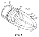
図1は、典型的な一実施形態に係るレンズカバーの典型的な斜視図である。レンズカバー105は、外面110および内面120と共に示されている。110と120との間の領域は、壁またはレンズカバー105の本体115とみなすことができる。レンズカバー105の内部は、開放形態を有するか、あるいは、固体または液体充填材料を含むことができる。いずれの場合も、以下に詳述するように、レンズカバー105の内部は、遮断部材130を含むことができる。
FIG. 1 is an exemplary perspective view of a lens cover according to an exemplary embodiment. The
レンズ本体115は、閉鎖遠位端140および近位開口部170を有する一般に細長い形状を有することができる。一態様では、遠位端140は、患者の外傷を最小にするために鈍い形状を有する。敏感な解剖学的領域において視覚化が必要とされる場合、遠位端140の形状によって、組織を損傷する可能性を減少させることができる。特に、遠位端140は、湾曲した遠位外面110を有することができる。図1の実施例では、レンズカバー105の横断面は円形である。ただし、他の断面を有する多くのレンズ形状が可能である。例えば、レンズカバーの横断面は、実質的に卵形または実質的に多角形とすることができる。また、レンズカバー本体の断面形状は、レンズカバーの長さに沿って変えることができる。
The
レンズカバー105によって、内視鏡(図1には示さず)と隣接する環境との間にオフセットを設けることができる。例えば、レンズカバーの本体115によって、内視鏡検出器とレンズカバーの遠位先端部との間に間隔を設けることができる。レンズカバーが組織と接触する場合、内視鏡とレンズカバーの遠位端との間のオフセットによって間隔が設けられるため、組織表面によって視覚化が完全に妨害されることはない。
The
レンズカバー105は、例えば、各種ポリマー、エラストマおよび/またはガラスを含む様々な透明または半透明の材料で製造することができる。材料の選択は、材料費、強度、光学的性質、レンズカバーの大きさ/形状および/またはレンズカバーの使用目的にある程度依存することができる。
The
一態様では、レンズカバー105によって、歪みを最小にするかあるいは全く生じさせずに光を本体115内に通過させることができる。別の態様では、レンズカバーの形状は、画像の歪曲、複数の媒体(例えば、液体および気体)を介する解剖学的構造の観察能力、鈍い遠位先端部の要望および/またはレンズカバーのオフセット間におけるトレードオフに基づいて選択することができる。一態様では、レンズカバーの外面は、湾曲した形状を有することができる。別の態様では、外面120の少なくとも一部は、扁球形状を有する。さらに別の態様では、外面120の少なくとも一部は、楕円体形状を有する。同様に、レンズカバーの内面は、湾曲した遠位面を有することができる。一態様では、レンズカバーの内面は、レンズカバーの外面に対応する形状を有する。
In one aspect, the
レンズカバー105の近位部分は、内視鏡および/または内視鏡を収容するための装置(例えば、カニューレ)と結合するように構成することができる。図1に示すように、レンズカバーの外面は、カニューレおよび/または内視鏡の遠位端に取り付けるための結合形状体(feature)160を含むことができる。例えば、溝、突起および/またはネジ山によって結合を容易にすることができる。当業者には明らかなように、レンズカバーの内面および/または外面によって様々な結合面を得ることができる。レンズカバー105を内視鏡または他のカメラ装置に取り付ける典型的な方法および機構としては、例えば、機械的インターロック、摩擦係合、接着剤、熱および/または他の溶接・取付け方法および装置の使用が挙げられる。また、レンズカバーは、恒久的または着脱可能に医療装置に結合させることができる。
The proximal portion of the
一態様では、レンズカバー105の近位部分は、画像検出器だけでなく光源と共に機能するように構成されている。例えば、以下に詳述するように、レンズカバー105内あるいはそこに隣接して配置される光源は、レンズカバー本体を通って光を照射することができる。
In one aspect, the proximal portion of the
上記レンズカバーの様々な典型的な態様に加えて、あるいは、それに代わるものとして、レンズカバー105は、同日に出願された発明「解剖学的構造を観察するための方法および装置」に記載されている様々な特徴を含むことができる。その開示内容全体が参照により本明細書に組み込まれるものとする。
In addition to or as an alternative to the various exemplary embodiments of the lens cover described above, the
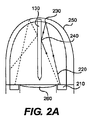
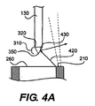
上述のように、レンズカバー105は、光がレンズカバーの一部から反射する際に生じる反射で照らし出されるアーチファクトを減少させるための遮断部材130を含むことができる。図2Aは、内視鏡および付属のレンズカバーの遠位端の典型的な分離断面図であり、典型的な一実施形態に係るレンズカバー内における典型的な光反射経路を示す。図示のように、検出器260は、レンズカバー本体250の内部から画像を捉えるように配置されている。検出器260は、例えばレンズまたはカメラアイ(camera eye)などの内視鏡の一部とすることができる。いくつかの実施形態では、内視鏡のカメラ部分は内視鏡の近位端に位置し、検出器260は遠位端に位置している。
As described above, the
この実施例では、光源210は、レンズカバー105を通して光を照射する。一態様では、光源は、一般に内視鏡検出器260を囲む光リング210であり、レンズカバー本体250の透明な部分の外側にある対象の解剖学的構造および/または組織を照らす。非環状形態を有する光源または検出器260を通して光を照射する光源などの他の光源および光源形態が可能である。
In this embodiment, the
図2Aに示すように、光路220などの光源210からの光の一部は、位置230などでレンズカバー250から内部反射する場合がある。遮断部材130が存在しない場合には、230で内部反射した光は検出器260内に伝播し続けるであろう。検出器が捕えた内部反射光によって、視覚化が損なわれる可能性がある。例えば、検出器の形態および/または画像処理ソフトウェアに応じて、内視鏡による視覚化画像中に、反射光によって、暗いまたは明るいリング(反射で照らし出されるアーチファクト)が出現する場合がある。当業者には明らかなように、反射光によって画像が不明瞭になる理由(すなわち、暗いリング、白点、グレアなど)よりも、遮断部材の使用によってそのようなアーチファクトの発生を減少させることが重要である。特に、レンズカバー105内に配置された遮断部材130によって、検出器260に反射する光の一部を、遮断部材130によって再誘導および/または吸収させる。例えば、図2Aに示すように、経路220に沿って伝播する光を、240で検出器260の外に反射させる。同様の実施例が図2Bに示されているが、そこには、遮断部材130によって屈折した後に検出器260の外255に反射している光225が示されている。
As shown in FIG. 2A, some of the light from the
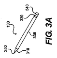
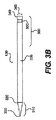
一実施形態では、遮断部材は、少なくともその一部がレンズカバー内に配置されるように構成された一般に細長い本体335を有する。例えば、図3Aおよび図3Bは、光が検出器に直接反射するのを防止するように構成された近位部分310およびレンズカバー105と結合するための遠位部分360を含む遮断部材130を示す。近位部分310と遠位部分360との間に示される遮断部材130は、一般に円筒形断面形状を有する。ただし、遮断部材130には、例えば、円形、矩形、楕円形、三角形、多角形および不規則な断面形状を含む様々な他の形状が可能である。また、細長い本体335は均一な幅を有するものとして示されているが、断面形状または幅は、遮断部材の長さに沿って変えることができる。
In one embodiment, the blocking member has a generally
一実施形態では、遮断部材を、1つの単一の部材から形成することができる。別の実施形態では、遮断部材130を、互いに結合した複数の部分から形成することができる。遮断部材は、開放内部を有することもできる。例えば、遮断部材は、近位端および/または遠位端によって遮断部材の内部が開放され、皮下注射管に類似した中空体を有することができる。開放内部の別の実施形態では、遮断部材は、1つの開放端のみを有する。
In one embodiment, the blocking member can be formed from one single member. In another embodiment, the blocking
遮断部材105の近位部分310は、光が検出器に直接反射するのを防止するように構成することができる。図4Aに示す一態様では、遮断部材110の近位部分は、実質的に350の点に到達する集束する縦断面幅を有する。光源210が経路420に沿って伝搬する光を発する場合、遮断部材130の近位外面によって、光は検出器には反射されずに、430で検出器260の外に反射される。
The
遮断部材130の近位部分310は、様々な光屈折形状を有することができる。図4Aに示す一態様では、集束する近位部分310は、実質的に円錐形状を有する。あるいは、近位部分310は、くさび形、ピラミッド形または他の傾斜形状を有することができる。また、近位先端部は、遮断部材の縦中心軸の中心に合わせる必要はない。例えば、近位断面の一面は、近位断面の他面よりも急な傾斜を有することができる。
The
また、遮断部材130の近位部分310にわたって示す集束は、図3Aおよび図3Bに示す遮断部材130の著しくより大きい部分よりも延ばすことができる。例えば、遮断部材130の長さ全体が、集束する断面幅を含むことができる。
Also, the convergence shown across the
先細り状近位先端部は、一般に任意の角度にすることができる。ただし、ほとんどの光を検出器260の外に反射させるために、先端部350は、約90°以下の範囲で角度をつけることができる。適当な角度は、遮断部材130の近位部分310に対する光源210の位置決め、検出器250と先端部350との間隔および/または光が光源210から投射される角度によって影響を受ける場合がある。一般に、近位先端部350の角度は、約1〜60°の範囲とすることができる。ただし、非常に小さい角度を含む1°に満たない角度によっても、優れた光の偏向を与えることができる。
The tapered proximal tip can generally be at any angle. However, in order to reflect most of the light out of the
一実施形態では、近位先端部350は鋭い点で集束する。鋭い点の最小表面積によって、遮断部材の先端から検出器に直接反射する光量を最小にすることができる。ただし、例えば、鋭い表面によって利用者に損傷を与える危険性が上昇することが懸念される場合には、遮断部材は鋭い点を有していなくてもよい。
In one embodiment, the
別の実施形態では、光を反射させる代わりに、あるいは、光を反射させることに加えて、遮断部材に光を吸収させて検出器に反射する光量を減少させることができる。図4Bに示すように、経路450に沿って伝搬する光は、遮断部材の近位部分310に到達する。検出器260に光を反射させずに、遮断部材の近位表面に光を吸収させることができる。本実施形態では、遮断部材は、先細り状近位部分310を有していてもよいし、有していなくてもよい。
In another embodiment, instead of reflecting light or in addition to reflecting light, the blocking member can absorb light and reduce the amount of light reflected to the detector. As shown in FIG. 4B, the light propagating along the
上述のように、遮断部材は、閉鎖端の代わりに開放近位端を含むことができる。例えば、遮断部材130の開放内部に光を受け入れることができる。中空型遮断部材の内面によって、検出器の外に光を反射することができかつ/または光を吸収させて検出器への反射を減少させることができる。このようにして、遮断部材130は、経路460に沿って検出器260に反射する光の量を減少させることができる。
As described above, the blocking member can include an open proximal end instead of a closed end. For example, light can be received inside the opening of the blocking
開放端型遮断部材130の外面は、遮断部材本体の近位部分で先細り状にすることもできる。例えば、開放端型または中空型遮断部材は、上記先細り状閉鎖端型遮断部材に類似した形態を有することができる。
The outer surface of the open
上述のように、遮断部材130の遠位端340は、レンズカバー105の一部と結合することができる。一態様では、結合を容易にするために、遮断部材は、結合形状体を含むことができる。例えば、遮断部材の遠位面は、(図3Bに示すような)溝330を含むことができる。ただし、別の実施形態では、遮断部材は、レンズカバーと結合するように構成された任意の表面形状体を含んでいない。遮断部材130の位置決めおよび/または様々な取付方法は、図6Cを参照しながら以下により詳細に述べる。
As described above, the
遮断部材130は、装置の用途に応じて、様々な材料で製造することができる。例えば、遮断部材130は、多種多様な従来の生体適合性外科材料、例えば、金属および/またはポリマーから形成することができる。当業者には明らかなように、様々な不透明または半透明材料を用いて遮断部材を形成することができる。
The blocking
遮断部材130の材料は、反射性にすることができる。通常は、一般に「反射性」とみなされる表面から発生する拡散反射はより少なくなる。例えば、いくつかの実施形態では、遮断部材130は、研摩された鏡状の外面を有することができる。特に、遮断部材を機械加工または研摩して遮断部材130に沿って発生する拡散反射量を減少させることができる。例えば、遮断部材130の近位端を研磨することによって、光を遮断部材130から予測可能な方向に反射させることができる。ただし、当然のことながら、反射で照らし出されるアーチファクトを効果的に減少させるために遮断部材を研摩する必要はない。
The material of the blocking
別の態様では、黒色の材料などの光吸収材料によって、反射で照らし出されるアーチファクトを減少または防止することができる。光を吸収させることによって、検出器260に向かう内部反射光の量を減少させることができる。
In another aspect, light absorbing materials, such as black materials, can reduce or prevent artifacts illuminated by reflection. By absorbing the light, the amount of internally reflected light toward the
ここで図5を参照すると、典型的な一実施形態に係る、遮断部材130を有するレンズカバー505の典型的な分離縦断面図が示されている。レンズカバー505によって、内視鏡とレンズカバー本体115の遠位端140との間にオフセットが設けられている。内視鏡がレンズカバーの内部まで延びる一態様では、オフセット510は、レンズカバーの全長に満たない長さを有する。例えば、内視鏡の遠位端が150で表される場合には、レンズカバー505によって設けられるオフセットはレンズカバーの全長に満たない長さにすることができる。一実施形態では、約8mm〜20mmの範囲のオフセットが設けられている。別の実施形態では、例えば、検出器がより広い円錐状の視野角を有する場合には、オフセットは約10mm〜14mmの範囲とすることができる。
Referring now to FIG. 5, an exemplary isolated longitudinal section of a
一般に、遮断部材130はオフセットの長さに満たない距離にわたって延在し、一実施形態では、遮断部材は、検出器の遠位端と遮断部材の近位端との間に間隔520を形成するような大きさである。間隔520によって、検出器560が遮断部材130の近位端と接触するのを防止する。遮断部材が鋭い近位端350を有する場合には、間隔520によって内視鏡の損傷および/または利用者の外傷を防止することができる。
Generally, the blocking
別の実施形態では、検出器560が遮断部材130と接触しないように、レンズカバーに保護ストッパー565を組み込むことができる。例えば、レンズカバーの内面は、内視鏡のレンズカバーに対する遠位移動を防止するように構成された小径の領域を含むことができる。ストッパー565は、レンズカバー505の一体化部分とすることおよび/または別個の部材によって形成することができる。その代わりとして、あるいは、追加として、内視鏡が遮断部材と接触する場合には、遮断部材130の近位端350は、損傷を防止するための柔らかい先端を含むことができる。
In another embodiment, a
光源、レンズカバーおよび検出器の形態に応じて、検出器に反射される光の経路を変えることができる。レンズカバーが湾曲した遠位面を有する一態様では、照射軸をレンズカバーの縦中心軸に沿って配置することができる。図6Aおよび図6Bは、レンズカバー505の縦中心軸Lを示す。反射で照らし出されるアーチファクトを生じさせる内部反射光の一部は、縦中心軸Lと交差する(あるいは交差に近い状態となる)。従って、縦中心軸Lに沿ってあるいはその近傍に遮断部材130を配置することによって、反射で照らし出されるアーチファクトを減少させることができる。そのような一実施形態では、遮断部材130は、レンズカバーの縦中心軸に実質的に平行に配置することができる。別の実施形態では、遮断部材130の縦中心軸LBがレンズカバー505の縦中心軸Lに実質的に位置合わせされるように、遮断部材130を配置する。
Depending on the configuration of the light source, lens cover and detector, the path of the light reflected by the detector can be changed. In one aspect where the lens cover has a curved distal surface, the illumination axis can be disposed along the longitudinal center axis of the lens cover. 6A and 6B show the longitudinal center axis L of the
オフセットおよび/またはレンズカバー505の曲率を変えることによって、内部反射光のパターンを変化させ、縦中心軸Lの異なる複数の点に沿って、より高輝度の内部反射光を生じさせることができる。従って、遮断部材130の長さを内部反射光の位置に基づいて選択することができる。特に、遮断部材130の長さは、これらの高輝度の点と交差するように選択することができる。
By changing the offset and / or the curvature of the
内部反射光の輝度は縦中心軸Lに沿った距離の関数として変化するが、最も濃度が高い内部反射光をレンズカバーの曲率中心の近傍に生じさせることができる。図6A〜図6Cに示す実施例では、曲率中心は、レンズカバーの遠位内面に近接して位置している。他の実施形態では、曲率中心の正確な位置は、レンズカバー形状のコンピュータ光学分析を実行することによって決定することができる。一態様では、遮断部材の少なくとも一部は、曲率中心の位置に従って配置される。 Although the brightness of the internally reflected light varies as a function of the distance along the longitudinal central axis L, the internally reflected light having the highest density can be generated in the vicinity of the center of curvature of the lens cover. In the embodiment shown in FIGS. 6A-6C, the center of curvature is located proximate to the distal inner surface of the lens cover. In other embodiments, the exact location of the center of curvature can be determined by performing a computer optical analysis of the lens cover shape. In one aspect, at least a portion of the blocking member is disposed according to the position of the center of curvature.
一態様では、遮断部材は、曲率中心のみを実質的に覆うことができる。別の実施形態では、遮断部材130は、曲率中心だけでなくそれ以上を覆うように構成することができる。これは、さらなる内部反射光が曲率中心以外の点でレンズカバーの縦中心軸L内を通過することができることから、有益な場合もある。
In one aspect, the blocking member can substantially cover only the center of curvature. In another embodiment, the blocking
図6Bに示す実施例では、この実施例における遮断部材130の断面縦幅を、約0.020インチとすることができる。断面縦幅は、レンズカバー505の形状、光源の位置および/またはレンズカバーの用途に応じて変えることができる。例えば、心臓の用途では、通常は幅を約0.001インチ〜0.050インチの範囲、別の態様では、約0.010インチ〜0.025インチの範囲とすることができる。ただし、遮断部材がレンズカバーの縦中心軸の近くで交差している光を依然として遮断できる限り、ほぼあらゆる断面縦幅が有用である。この点に関しては、より大きな断面縦幅(すなわち直径)を有する遮断部材130であれば、より細い遮断部材よりも正確に配置する必要はない。ただし、遮断部材自体によって内視鏡の視界が損なわれるため、遮断部材幅を最小にする際にもいくつかのトレードオフが存在する。
In the embodiment shown in FIG. 6B, the cross-sectional vertical width of the blocking
実施形態に応じて、遮断部材130をレンズカバー505に取り付けるための様々な方法が存在する。図6Cは、典型的な一実施形態に係る、レンズカバーと遮断部材との境界面の拡大図を有するレンズカバー505の典型的な分離縦断面図である。
Depending on the embodiment, there are various methods for attaching the blocking
一実施形態では、遮断部材は、表面形状体または結合のための形状体を含む。例えば、図6Cの遮断部材は、遠位端340の近傍に溝を含む。一態様では、レンズカバーを、遮断部材130の溝330の周囲に形成することができる。あるいは、溝によって、遮断部材130をスナップ嵌めまたは締り嵌めを介してレンズカバーと結合させることができる。
In one embodiment, the blocking member includes a surface feature or a shape for bonding. For example, the blocking member of FIG. 6C includes a groove near the
図6Cには溝が示されているが、結合面形状体を突起または隆起とすることができる。突出する結合形状体による視覚化への影響を減少させるために、突起または隆起を透明にすることができる。 Although grooves are shown in FIG. 6C, the mating surface features can be protrusions or ridges. In order to reduce the visual impact of protruding coupling features, the protrusions or ridges can be transparent.
微笑規模の粗さを有するテクスチャー加工された表面(例えば、グリットブラストによって創出される表面)によっても、遮断部材とレンズカバーとの間の結合の質を向上させることができる。 A textured surface with a smile-scale roughness (eg, a surface created by grit blasting) can also improve the quality of the bond between the blocking member and the lens cover.
また、一実施形態では、遮断部材は、レンズカバーと結合する表面形状体を必要としない。例えば、遮断部材は、平滑な外面を有することができる。遮断部材とレンズカバーとの摩擦結合および/または接着性結合によって十分な保持を得ることができる。 Further, in one embodiment, the blocking member does not require a surface shape body that is coupled to the lens cover. For example, the blocking member can have a smooth outer surface. Sufficient retention can be obtained by frictional and / or adhesive bonding between the blocking member and the lens cover.
いくつかの実施形態では、遮断部材を、レンズカバー505の内部領域に実質的に含めることができる。他の実施形態では、遮断部材130の遠位部分を、レンズカバー505の外壁110の遠位140から突出させることができる。突出する遮断部材130を有する実施形態では、鈍い遠位面を得るために、遮断部材130の遠位端340を機械加工するか、あるいは滑らかにすることができる。追加として、あるいは、その代わりとして、追加の保護カバーを、遮断部材の突出する遠位端340を覆って配置することができる。いくつかの実施形態では、この追加の保護カバー(図示せず)を透明にすることができる。
In some embodiments, a blocking member can be substantially included in the interior region of the
さらに別の実施形態では、遮断部材は、レンズカバーの本体を貫通させずにレンズカバーの表面と結合させることができる。例えば、遮断部材の最遠位表面は、レンズカバーを貫通させずにレンズカバーの近位表面に結合させることができる。 In yet another embodiment, the blocking member can be coupled to the surface of the lens cover without penetrating the lens cover body. For example, the distal most surface of the blocking member can be coupled to the proximal surface of the lens cover without penetrating the lens cover.
図示の実施形態は、一般にレンズカバーに直接結合した遮断部材を示しているが、別の態様では、遮断部材とレンズカバーとの間に中間物を配置することができる。例えば、中間パッドによって、レンズカバー505への接着のためにより大きな表面積を得ることができる。例えば、パッドは、レンズカバー本体115の内面120に沿って配置することができる。実施形態に応じて、パッドをレンズカバーに取り付ける前または後に、遮断部材130を中間パッドに取り付けることができる。これらのいくつかの実施形態では、中間パッドは透明である。また、中間パッドを取り付けるために用いる接着剤を透明にすることができる。
Although the illustrated embodiment shows a blocking member that is generally coupled directly to the lens cover, in another aspect, an intermediate can be disposed between the blocking member and the lens cover. For example, the intermediate pad can provide a larger surface area for adhesion to the
上記様々な実施形態は、遮断部材の遠位端を介してレンズカバーに結合させる遮断部材に一般に適合するが、遮断部材の近位端をレンズカバーに結合させることも想定される。図6Dは、遮断部材の近位端がレンズカバーの近位部分に取付けられたレンズカバーの典型的な図である。遮断部材は、レンズカバー505の内部領域にある透明な部材630と結合する。
While the various embodiments above are generally compatible with a blocking member that is coupled to the lens cover via the distal end of the blocking member, it is also envisioned that the proximal end of the blocking member is coupled to the lens cover. FIG. 6D is an exemplary view of a lens cover with the proximal end of the blocking member attached to the proximal portion of the lens cover. The blocking member is combined with the
さらに別の実施形態では、遮断部材を内視鏡、検出器および/またはカニューレに直接結合させることができる。例えば、検出器を遮断部材130の近位部分と結合させることができる。これらの実施形態では、レンズカバーが内視鏡、カニューレおよび/または検出器の遠位部分に取り付けられている場合には、遠位に延在する遮断部材130を、レンズカバー505内まで拡張させることができる。
In yet another embodiment, the blocking member can be directly coupled to the endoscope, detector and / or cannula. For example, the detector can be coupled to the proximal portion of the blocking
図7Aは、典型的な一実施形態に係る医療装置710の斜視図である。医療装置710は、近位端と遠位端との間に延在し、光学経路を収容するカニューレ770を含むことができる。カニューレ770の遠位端730に配置されるレンズカバー740によって、例えば、内視鏡などの光学装置による視覚化が可能となる。光学装置は、医療装置の本体とは別個の部材として一般に記載されているが、一態様では、光学装置は装置710に組み込まれている。
FIG. 7A is a perspective view of a
カニューレ770は、開放遠位端712を有する第1の内腔および開放遠位端714を有する第2の内腔を含むこともできる。これらの開口部は、カニューレ770の遠位端730またはその近傍に設けることができる。2つの開放端型内腔を示しているが、単一の内腔または3つ以上の開放端型内腔を医療装置710と共に使用することができる。
一態様では、第1の手術用ツール760を第1の内腔に収容することができ、第2の手術用ツール750を第2の内腔に収容することができる。当業者には明らかなように、装置710の用途に応じて、様々なツールを内腔を通して誘導することができる。
In one aspect, the first
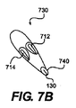
医療装置710の遠位端730を図7Bに示す。図示のように、装置710の最遠位表面は、レンズカバー740によって画定されている。装置710を敏感な解剖学的構造に近接して使用する場合には、レンズカバーによって鈍い遠位面を設けることができる。そのような一実施形態では、レンズカバーは、湾曲した最遠位表面を有する。別の態様では、レンズカバー740は、回転卵形などの卵形状を有する。さらに別の態様では、レンズカバー740の遠位部分は、楕円体形状によって画定されている。
The
別の態様では、レンズカバーは、円錐形状を有するか、あるいは、円錐形要素および湾曲要素を有する複合型横断面を有することができる。この種の「鋭い」形状は、組織の切開および他の類似した操作に有用である。 In another aspect, the lens cover may have a conical shape, or a composite cross section having conical and curved elements. This type of “sharp” shape is useful for tissue incisions and other similar manipulations.
また、外面110の形状は、内面120の形状とは異なっていてもよい。これは、一実施形態では、レンズとして機能するレンズカバーを創出するのに有用な場合もある。例えば、レンズカバーによって、いくつかの用途で使用される拡大効果または魚眼効果を創出することができる。
Further, the shape of the
上記遮断部材と共に使用される装置の一つの例は、LEXVIEW一方向ルーティングシステム(マサチューセッツ州ナティック所在のBoston Scientific社製(インディアナ州インディアナポリス所在の旧Guidant Corporation社製)である。FLEXVIEWは、細長い本体、内視鏡用内腔および作業用内腔を有するルーティング装置である。レンズカバー740は、内視鏡ならびにルーティングスネアと共に使用される。FLEXVIEWレンズカバー740は、利用者によって内視鏡から着脱することができる。ルーティングスネアは、利用者によってレンズカバーの周囲への巻き付けおよび結び付けが可能であり、FLEX10切除プローブの設置を容易にすることを目的とする。(付属のレンズカバーを有する)内視鏡およびスネアは、患者の体の小さな穴を通して挿入される。次いで、レンズカバーおよび内視鏡を用いて解剖学的構造を視覚化し、所望どおりにルーティングスネアを配置する。適切な位置に配置したら、ルーティングスネアを使用して切除プローブを配置する。切除プローブはマイクロ波エネルギを心臓組織に集束させるために用いられる。
One example of a device used with the blocking member is a LEXVIEW one-way routing system (manufactured by Boston Scientific, Natick, Massachusetts (formerly Guidant Corporation, Indianapolis, Indiana). FLEXVIEW is an elongated body. The
ルーティング工程は、内視鏡およびレンズカバー740を用いることにより視覚化される。本明細書中の様々な実施形態において開示されているように、レンズカバー本体および遮断部材を用いることによって、反射で照らし出されるアーチファクトを減少させ、処置全体にわたって視覚化の質を向上させることができる。本明細書に記載されている遮断部材と共に使用することができる装置の別の例は、マサチューセッツ州ナティック所在のBoston Scientific社製(インディアナ州インディアナポリス所在の旧Guidant Corporation社製)VASOVIEW内視鏡的血管採取システムである。VASOVIEW装置は、内視鏡用チャネルおよび例えばバイセクター(bisector)またははさみなどの手術用ツールを誘導するための一つ以上の作業用チャネルを有する本体を含む。レンズカバーを、内視鏡による視覚化が可能となるようにVASOVIEW本体および/または内視鏡と結合させることができる。特に、レンズカバーによって内視鏡用チャネルを覆うことができる。いくつかのVASOVIEWの実施形態に関する詳細な情報は、米国特許第5,895,353号、第5,993,384号、第6,176,825号、第6,406,425号、第6,830,546号、第5,595,353号、第5,976,168号および第5,980,549号に記載されている。それらの開示内容は参照により本明細書に組み込まれるものとする。
The routing process is visualized by using an endoscope and
図8Aは、上記内視鏡的血管採取システムの一実施形態に一致する医療装置の一実施例の斜視図である。図8Aは、拡張位置で血管マニピュレータ840を収容するカニューレ810の一実施例を示す。カニューレ810は、長さがほぼ12インチ〜18インチであってもよい、polymed UDなどの生体不活性材料からなる外部ハウジングを含む(他の長さも可能である)。カニューレ810の近位端は、血管マニピュレータ112の平行移動を制御する血管マニピュレータ112に連結された血管マニピュレータ駆動部を含むハンドル内に配置されている。図示のカニューレ810は、血管マニピュレータ112だけでなく、内視鏡およびバイセクターツール130も収容している。ハンドルは、バイセクターツール830および/または血管マニピュレータ840を制御するためのさらなるツール制御装置845を含む。従って、ツール制御装置845および血管マニピュレータ駆動部835は、これらのツールの制御を可能にするいくつかの方法でバイセクターツール830および血管マニピュレータ840に連結されている。
FIG. 8A is a perspective view of one example of a medical device consistent with one embodiment of the endoscopic blood vessel collection system. FIG. 8A shows an example of a
図8Bは、図8Aに示す医療装置の一実施例の遠位部分の斜視図である。内腔を含む内視鏡820は、カニューレ810内に収容されている。ただし、一実施形態では、内視鏡820は、カニューレ810の一体化部分であってもよい。実施形態に応じて、遮断部材を有するレンズカバー105を、内視鏡820、内腔またはカニューレ810に取り付けることができる。別の実施形態では、レンズカバー105は、内視鏡、内腔またはカニューレにすでに組み込まれていてもよい。上記視覚の利点に加えて、レンズカバーに遮断部材を設けることにより、組織分離がより容易になることもある。一実施形態は、レンズカバーを洗浄して内視鏡による視覚化を不明瞭にする壊死組織片を除去するために、レンズカバー105上に流体を噴霧するためのノズル850含むことができる。
FIG. 8B is a perspective view of the distal portion of one embodiment of the medical device shown in FIG. 8A. An
他の実施形態は、本明細書に開示された実施形態の詳細および実施を考察することにより当業者には明らかである。その詳細および実施例は単なる例示であって、正確な範囲および趣旨は添付の特許請求の範囲に示されている。 Other embodiments will be apparent to those skilled in the art from consideration of the details and practice of the embodiments disclosed herein. The details and examples are illustrative only, with the exact scope and spirit being indicated in the appended claims.
Claims (38)
レンズカバーであって、前記レンズカバーが、
内面および外面を画定する少なくとも部分的に透明な壁であって、前記壁が、近位端および遠位端と、前記外面の少なくとも一部における湾曲と、前記外面の遠位端の鈍い先端と、開放内部領域と、を備え、前記壁が、前記壁の遠位部分を通じて対象の視認性を与える、壁と、
遠位端および近位端を有する細長い光遮断部材であって、前記光遮断部材が、前記レンズカバーの縦中心軸の少なくとも一部を通じて延在する、光遮断部材と、を備える、レンズカバーと、
前記レンズカバーを通じて光を照射するための光源と、
前記レンズカバーを通じて視認性を与えるための検出器であって、前記検出器が、前記レンズカバーの内面の観察を可能にするように、前記レンズカバーに対して相対的に位置する、検出器と、を備え、
前記レンズカバーの前記光遮断部材が棒として構成され、かつ、そうでなければ前記検出器に反射することになるだろう、前記光源からの光の少なくとも一部を遮断し、前記光遮断部材の遠位端が、前記壁の内面から前記検出器に向かって近位に延在する、医療システム。 A medical system for observing internal anatomy , said system comprising :
A lens cover, the lens cover,
An at least partially transparent wall defining an inner surface and an outer surface, wherein the wall includes a proximal end and a distal end, a curvature at at least a portion of the outer surface, and a blunt tip at the distal end of the outer surface. includes an open interior region, wherein the wall, providing the visibility of target distal part before Kikabe through the wall,
An elongate light shielding member to have a distal end and a proximal end, said light blocking member extends through its at least part of the longitudinal center axis of the lens cover, comprising a light blocking member, a , Lens cover,
A light source for irradiating light through the lens cover;
A detector for providing visibility through the lens cover, wherein the detector is positioned relative to the lens cover so as to allow observation of the inner surface of the lens cover; , equipped with a,
The light blocking member of the lens cover is configured as a rod and blocks at least a portion of the light from the light source that would otherwise be reflected to the detector; A medical system, wherein a distal end extends proximally from the inner surface of the wall toward the detector .
開放近位端と、空洞部を画定する内面と、前記開放近位端に対向する閉鎖遠位端と、を有する細長く剛性の本体を備えるレンズカバーと、
前記レンズカバーを通じて光を照射するように構成された光源と、
前記レンズカバーを通じて視認性を与えるための検出器であって、前記検出器が、前記レンズカバーの内面の観察を可能にするように、前記レンズカバーに対して相対的に位置する、検出器と、
棒として構成され、かつ、そうでなければ前記検出器に反射することになるだろう、前記光源からの光の少なくとも一部を遮断するように、前記レンズカバーに対して相対的に配置されている光遮断部材であって、前記光遮断部材の遠位端が前記内面から突出し、前記光遮断部材が、前記内面から前記検出器に向かって近位に延在する、光遮断部材と、
を含む、医療システム。 A medical system for observing internal anatomy, the medical system comprising:
An open proximal end, an inner surface defining a cavity, and a closed distal end opposite to said open proximal end, a lens cover comprising an elongate rather rigid body having,
A light source configured to emit light through the lens cover;
A detector for providing visibility through the lens cover, the detector, so as to allow observation of the inner surface of the lens cover, relative position with respect to the lens cover, inspection can When,
Arranged as a rod and positioned relative to the lens cover so as to block at least part of the light from the light source that would otherwise be reflected to the detector an optical shielding sectional member have, projecting from the distal end the inner surface of the light blocking member, the light blocking member extends proximally toward said detector from said inner surface, and a light blocking member,
Including a medical system .
光学装置の遠位領域に位置する光源であって、前記光源が、遠位方向に光を投射するように構成されている、光源と、 A light source located in a distal region of the optical device, wherein the light source is configured to project light in a distal direction;
前記光学装置の遠位領域に位置する検出器であって、前記検出器が、前記検出器に対して遠位方向に観察される画像を受信するように構成されている、検出器と、 A detector located in a distal region of the optical device, wherein the detector is configured to receive an image viewed in a distal direction relative to the detector;
前記光学装置の遠位領域と結合するように構成された細長いレンズカバーであって、前記レンズカバーが、閉鎖遠位端と、内部表面と、外部表面と、前記内部表面および前記外部表面の間にある側壁と、を備え、前記側壁が、前記光源から投射された光が(i)前記レンズカバーを通過し、かつ(ii)前記レンズカバーから内部反射することを可能にする内部領域を包囲する、レンズカバーと、 An elongate lens cover configured to couple with a distal region of the optical device, the lens cover being between a closed distal end, an inner surface, an outer surface, and the inner surface and the outer surface. And the side wall surrounds an internal region that allows light projected from the light source to (i) pass through the lens cover and (ii) internally reflect from the lens cover. To the lens cover,
前記レンズカバーの内部表面から突出しており、前記検出器に向かって近位方向に延在し、前記光源および前記検出器に対して遠位で、かつ前記光源および前記検出器から離間した位置で終端する細長い光遮断部材であって、前記光遮断部材は、前記光源から放射し、前記レンズカバーから内部反射し、最終的に前記検出器により受け入れることができる光の量を減少させるように構成されている、光遮断部材と、 Projecting from the inner surface of the lens cover, extending proximally toward the detector, distal to the light source and the detector and spaced from the light source and the detector A terminating elongated light blocking member configured to reduce the amount of light emitted from the light source, internally reflected from the lens cover, and finally received by the detector. A light blocking member,
を備える、医療システム。A medical system comprising:
近位端および遠位端を有する内視鏡であって、前記内視鏡の遠位端が画像を受信するための検出器を含む、内視鏡と、 An endoscope having a proximal end and a distal end, wherein the endoscope includes a detector for receiving an image;
前記内視鏡と動作的に関連するレンズカバーであって、前記レンズカバーが、 A lens cover operatively associated with the endoscope, the lens cover comprising:
前記レンズカバーの内面および外面を画定する前記少なくとも部分的に透明な壁であって、前記少なくとも部分的に透明な壁が剛性であり、かつ、前記内視鏡が前記少なくとも部分的に透明な壁の一部を通じて対象を観察することを可能にするように構成されている、壁と、 The at least partially transparent wall defining an inner surface and an outer surface of the lens cover, wherein the at least partially transparent wall is rigid and the endoscope is the at least partially transparent wall; A wall configured to allow observation of an object through a portion of the
近位端と、 A proximal end;
遠位端と、 The distal end;
前記少なくとも部分的に透明な壁の外面の少なくとも一部にわたる湾曲と、 Curvature over at least a portion of the outer surface of the at least partially transparent wall;
前記レンズカバーの遠位端および前記少なくとも部分的に透明な壁の外面に位置する鈍い先端と、 A blunt tip located on a distal end of the lens cover and an outer surface of the at least partially transparent wall;
開放内部領域と、 An open interior area;
遠位端および近位端を有する細長い光遮断部材であって、前記光遮断部材が、前記レンズカバーの縦中心軸の少なくとも一部を通じて延在し、前記光遮断部材の遠位端が前記内面から突出しており、前記光遮断部材が細長い本体を備え、ある長さの前記細長い本体が、前記内面から前記検出器に向かって近位に延在し、かつ前記検出器に対して遠位に位置する近位端で終端し、前記光遮断部材が、前記内面から前記検出器の外に反射される光を反射するように構成されている、光遮断部材と、を備える、レンズカバーと、 An elongated light blocking member having a distal end and a proximal end, wherein the light blocking member extends through at least a portion of a longitudinal central axis of the lens cover, and the distal end of the light blocking member is the inner surface. The light blocking member comprises an elongate body, a length of the elongate body extending proximally from the inner surface toward the detector and distal to the detector A lens cover comprising: a light blocking member that terminates at a proximal end that is located, and wherein the light blocking member is configured to reflect light reflected from the inner surface to the outside of the detector;
を備える、医療システム。A medical system comprising:
その遠位端に検出器を有する細長い光学装置と、 An elongated optical device having a detector at its distal end;
第1の内腔を包含するカニューレであって、前記第1の内腔が前記細長い光学装置を受け入れるように構成されている、カニューレと、 A cannula including a first lumen, wherein the first lumen is configured to receive the elongated optical device;
レンズカバーであって、前記レンズカバーが、細長い形状を有する本体と、閉鎖遠位先端と、縦中心軸と、開放内部領域と、湾曲部分を有する外面と、を備え、前記レンズカバーの本体の透明な遠位部分が、前記閉鎖遠位先端に向かって先細る先細り状形状を有する、レンズカバーと、 A lens cover, comprising: a body having an elongated shape; a closed distal tip; a longitudinal center axis; an open inner region; and an outer surface having a curved portion. A lens cover, wherein the transparent distal portion has a tapered shape tapering toward the closed distal tip;
前記レンズカバーの閉鎖遠位先端に対して近位に位置し、かつ、前記レンズカバーの開放内部領域を通じて遠位方向に光を照射するように構成されている光源と、 A light source positioned proximal to the closed distal tip of the lens cover and configured to illuminate distally through an open interior region of the lens cover;
そうでなければ前記検出器に反射することになるだろう、前記光源からの光の少なくとも一部を遮断するための細長い光遮断部材であって、前記光遮断部材が遠位端および近位端を有し、前記光遮断部材の近位端が、前記光源に対して遠位にかつ前記光源から離間して配置されており、前記光遮断部材の遠位端が、前記レンズカバーの外面内に包含され、かつ前記レンズカバーの縦中心軸に対して平行に整列されている、光遮断部材と、 An elongate light blocking member for blocking at least a portion of the light from the light source that would otherwise be reflected to the detector, the light blocking member having a distal end and a proximal end A proximal end of the light blocking member is disposed distal to and spaced from the light source, the distal end of the light blocking member being within the outer surface of the lens cover And a light blocking member that is aligned parallel to the longitudinal center axis of the lens cover;
を備える、医療システム。A medical system comprising:
開放近位端と、空洞部を画定する内面と、前記開放近位端に対向する閉鎖遠位端と、を有する細長い本体を備えるレンズカバーと、 A lens cover comprising an elongated body having an open proximal end, an inner surface defining a cavity, and a closed distal end opposite the open proximal end;
前記レンズカバーを通じて光を照射するように構成された光源と、 A light source configured to emit light through the lens cover;
前記レンズカバーを通じて視認性を与えるための検出器であって、前記検出器が、前記レンズカバーの内面の観察を可能にするように、前記レンズカバーに対して相対的に位置する、検出器と、 A detector for providing visibility through the lens cover, wherein the detector is positioned relative to the lens cover so as to allow observation of the inner surface of the lens cover; ,
そうでなければ前記検出器に反射することになるだろう、前記光源からの光の少なくとも一部を遮断するための光遮断部材であって、前記光遮断部材が細長い本体を有し、前記光遮断部材の遠位端が前記内面から突出しており、前記光遮断部材が、前記内面から前記検出器に向かって近位に延在し、かつ、前記レンズカバーの閉鎖遠位端および前記検出器の遠位端の間に位置する近位端で終端し、前記光遮断部材の近位端が先細り状の先端として構成されている、光遮断部材と、 A light blocking member for blocking at least a portion of the light from the light source that would otherwise be reflected by the detector, the light blocking member having an elongated body, and the light A distal end of a blocking member projects from the inner surface, the light blocking member extends proximally from the inner surface toward the detector, and the closed distal end of the lens cover and the detector A light blocking member terminating at a proximal end located between the distal ends of the light blocking member, wherein the proximal end of the light blocking member is configured as a tapered tip;
を備える、医療システム。A medical system comprising:
開放近位端と、空洞部を画定する内面と、前記開放近位端に対向する閉鎖遠位端と、を有する細長い本体を備えるレンズカバーと、 A lens cover comprising an elongated body having an open proximal end, an inner surface defining a cavity, and a closed distal end opposite the open proximal end;
前記レンズカバーを通じて光を照射するように構成された光源と、 A light source configured to emit light through the lens cover;
前記レンズカバーを通じて視認性を与えるための検出器であって、前記検出器が、前記レンズカバーの内面の観察を可能にするように、前記レンズカバーに対して相対的に位置する、検出器と、 A detector for providing visibility through the lens cover, wherein the detector is positioned relative to the lens cover so as to allow observation of the inner surface of the lens cover; ,
そうでなければ前記検出器に反射することになるだろう、前記光源からの光の少なくとも一部を遮断するための光遮断部材であって、前記光遮断部材の遠位端が前記内面から突出しており、前記光遮断部材が、前記内面から前記検出器に向かって近位に延在し、かつ、前記検出器の遠位端に対して遠位にかつ前記遠位端から離間して位置する近位端で終端する、光遮断部材と、 A light blocking member for blocking at least a portion of the light from the light source that would otherwise be reflected by the detector, the distal end of the light blocking member protruding from the inner surface. The light blocking member extends proximally from the inner surface toward the detector and is located distally and spaced from the distal end of the detector. A light blocking member that terminates at a proximal end that
を備える、医療システム。A medical system comprising:
Applications Claiming Priority (3)
| Application Number | Priority Date | Filing Date | Title |
|---|---|---|---|
| US90715007P | 2007-03-22 | 2007-03-22 | |
| US60/907,150 | 2007-03-22 | ||
| PCT/US2008/003729 WO2008115575A1 (en) | 2007-03-22 | 2008-03-21 | Methods and devices for reducing reflection-illuminated artifacts |
Publications (3)
| Publication Number | Publication Date |
|---|---|
| JP2010522025A JP2010522025A (en) | 2010-07-01 |
| JP2010522025A5 JP2010522025A5 (en) | 2011-07-07 |
| JP5498174B2 true JP5498174B2 (en) | 2014-05-21 |
Family
ID=39521863
Family Applications (1)
| Application Number | Title | Priority Date | Filing Date |
|---|---|---|---|
| JP2009554583A Active JP5498174B2 (en) | 2007-03-22 | 2008-03-21 | Device for reducing artifacts illuminated by reflections |
Country Status (4)
| Country | Link |
|---|---|
| US (1) | US8414480B2 (en) |
| EP (2) | EP3391803B1 (en) |
| JP (1) | JP5498174B2 (en) |
| WO (1) | WO2008115575A1 (en) |
Families Citing this family (24)
| Publication number | Priority date | Publication date | Assignee | Title |
|---|---|---|---|---|
| US9211059B2 (en) | 2007-06-19 | 2015-12-15 | Minimally Invasive Devices, Inc. | Systems and methods for optimizing and maintaining visualization of a surgical field during the use of surgical scopes |
| US8888689B2 (en) | 2007-06-19 | 2014-11-18 | Minimally Invasive Devices, Inc. | Systems and methods for optimizing and maintaining visualization of a surgical field during the use of surgical scopes |
| US9050036B2 (en) | 2007-06-19 | 2015-06-09 | Minimally Invasive Devices, Inc. | Device for maintaining visualization with surgical scopes |
| JP2010279526A (en) * | 2009-06-04 | 2010-12-16 | Fujifilm Corp | Endoscopic image processing apparatus, method and program |
| US9636092B2 (en) | 2010-07-17 | 2017-05-02 | Debra A. KING | Methods and systems for minimally invasive endoscopic surgeries |
| WO2012075487A2 (en) | 2010-12-03 | 2012-06-07 | Minimally Invasive Devices, Llc | Devices, systems, and methods for performing endoscopic surgical procedures |
| AU2012209090B2 (en) | 2011-01-25 | 2016-03-24 | Boston Scientific Scimed, Inc. | Systems and methods for maintaining a narrow body lumen |
| IL215106A0 (en) * | 2011-09-12 | 2012-02-29 | Daniel Sherwin | Laparoscopic device |
| DE102012205598A1 (en) * | 2012-04-04 | 2013-10-10 | Henke-Sass, Wolf Gmbh | Protective sleeve for an endoscope tube having endoscope |
| US9814481B2 (en) * | 2013-03-14 | 2017-11-14 | Saphena Medical, Inc. | Unitary endoscopic vessel harvesting devices |
| EP2967629B1 (en) | 2013-03-14 | 2019-05-29 | Saphena Medical, Inc. | Unitary endoscopic vessel harvesting devices |
| US10398292B2 (en) | 2013-03-14 | 2019-09-03 | Floshield, Inc. | Fluid dispensing control systems and methods |
| US20180078120A1 (en) * | 2015-04-16 | 2018-03-22 | Floshield, Inc. | Endoscope having integrated visual field enhancement system |
| US9943328B2 (en) | 2015-04-28 | 2018-04-17 | Saphena Medical, Inc. | Unitary endoscopic vessel harvesting devices with an elastic force |
| WO2016205514A1 (en) | 2015-06-17 | 2016-12-22 | Saphena Medical, Inc. | Unitary endoscopic vessel harvesting devices |
| US20180317755A1 (en) * | 2015-07-10 | 2018-11-08 | Sharp Kabushiki Kaisha | In-body image capturing device and in-body monitoring camera system |
| WO2018170903A1 (en) | 2017-03-24 | 2018-09-27 | Covidien Lp | Endoscopes and methods of treatment |
| EP3539450B1 (en) | 2018-03-14 | 2024-01-24 | Ambu A/S | A tip part for a vision device |
| EP3613327A1 (en) | 2018-08-24 | 2020-02-26 | Ambu A/S | A tip part for a vision device |
| US11311184B2 (en) | 2018-08-24 | 2022-04-26 | Ambu A/S | Tip part for a vision device |
| EP3613326B1 (en) * | 2018-08-24 | 2023-09-20 | Ambu A/S | A tip part for a vision device |
| US11938662B2 (en) | 2019-09-06 | 2024-03-26 | Ambu A/S | Tip part assembly for an endoscope |
| WO2021127053A1 (en) * | 2019-12-17 | 2021-06-24 | GI Scientific, LLC | Optical components for endoscope companion devices |
| EP4011270A1 (en) | 2020-12-08 | 2022-06-15 | Ambu A/S | Endoscope tip part with improved optical properties |
Family Cites Families (26)
| Publication number | Priority date | Publication date | Assignee | Title |
|---|---|---|---|---|
| US3859539A (en) * | 1973-04-25 | 1975-01-07 | Instrumentation Specialties Co | Optical system |
| US4961738A (en) * | 1987-01-28 | 1990-10-09 | Mackin Robert A | Angioplasty catheter with illumination and visualization within angioplasty balloon |
| US5193525A (en) * | 1990-11-30 | 1993-03-16 | Vision Sciences | Antiglare tip in a sheath for an endoscope |
| JP3007712B2 (en) * | 1991-03-22 | 2000-02-07 | 株式会社キーエンス | Fiber illumination type imaging device |
| JPH07294828A (en) * | 1994-04-27 | 1995-11-10 | Olympus Optical Co Ltd | Endoscope with protection cover |
| GB9417048D0 (en) | 1994-08-24 | 1994-10-12 | Kodak Ltd | Improvements in and relating to film cassettes |
| US5980549A (en) | 1995-07-13 | 1999-11-09 | Origin Medsystems, Inc. | Tissue separation cannula with dissection probe and method |
| JP3519823B2 (en) * | 1995-05-31 | 2004-04-19 | オリンパス株式会社 | Cover-type endoscope |
| DE19525995C1 (en) * | 1995-07-17 | 1996-07-04 | Winter & Ibe Olympus | Endoscope lens with light mask |
| JP3086204B2 (en) * | 1997-12-13 | 2000-09-11 | 株式会社アコウル | Omnidirectional imaging device |
| US6176825B1 (en) | 1998-06-22 | 2001-01-23 | Origin Medsystems, Inc. | Cannula-based irrigation system and method |
| US6406425B1 (en) | 1998-06-22 | 2002-06-18 | Origin Medasystems | Cannula-based irrigation system and method |
| US6830546B1 (en) | 1998-06-22 | 2004-12-14 | Origin Medsystems, Inc. | Device and method for remote vessel ligation |
| US5895353A (en) | 1998-06-22 | 1999-04-20 | Origin Medsystems, Inc. | Vessel isolating retractor cannula and method |
| US6692430B2 (en) * | 2000-04-10 | 2004-02-17 | C2Cure Inc. | Intra vascular imaging apparatus |
| US7347817B2 (en) * | 2001-08-02 | 2008-03-25 | Given Imaging Ltd. | Polarized in vivo imaging device, system and method |
| JP2003195170A (en) * | 2001-10-19 | 2003-07-09 | Tateyama R & D:Kk | Panoramic image block |
| DE10236240A1 (en) * | 2002-02-06 | 2003-08-14 | Roehm Gmbh | Silicone graft copolymers with core-shell structure, impact-modified molding compositions and moldings, and process for their preparation |
| JP2003279862A (en) * | 2002-03-25 | 2003-10-02 | Machida Endscope Co Ltd | Omnidirectional endoscopic device |
| US7662094B2 (en) * | 2002-05-14 | 2010-02-16 | Given Imaging Ltd. | Optical head assembly with dome, and device for use thereof |
| WO2003101287A2 (en) * | 2002-05-30 | 2003-12-11 | The Board Of Trustees Of The Leland Stanford Junior University | Apparatus and method for coronary sinus access |
| JP2005074031A (en) * | 2003-09-01 | 2005-03-24 | Pentax Corp | Capsule endoscope |
| US7824327B2 (en) * | 2005-04-12 | 2010-11-02 | Tyco Healthcare Group Llp | Optical trocar with scope holding assembly |
| US8932208B2 (en) * | 2005-05-26 | 2015-01-13 | Maquet Cardiovascular Llc | Apparatus and methods for performing minimally-invasive surgical procedures |
| US20060270900A1 (en) * | 2005-05-26 | 2006-11-30 | Chin Albert K | Apparatus and methods for performing ablation |
| US20070167834A1 (en) * | 2005-12-29 | 2007-07-19 | Amit Pascal | In-vivo imaging optical device and method |
-
2008
- 2008-03-21 WO PCT/US2008/003729 patent/WO2008115575A1/en active Application Filing
- 2008-03-21 EP EP18173587.9A patent/EP3391803B1/en active Active
- 2008-03-21 JP JP2009554583A patent/JP5498174B2/en active Active
- 2008-03-21 US US12/053,065 patent/US8414480B2/en active Active
- 2008-03-21 EP EP08742179.8A patent/EP2136695B1/en active Active
Also Published As
| Publication number | Publication date |
|---|---|
| EP2136695A1 (en) | 2009-12-30 |
| EP3391803A1 (en) | 2018-10-24 |
| US20080255419A1 (en) | 2008-10-16 |
| EP2136695B1 (en) | 2018-05-23 |
| WO2008115575A1 (en) | 2008-09-25 |
| JP2010522025A (en) | 2010-07-01 |
| US8414480B2 (en) | 2013-04-09 |
| EP3391803B1 (en) | 2019-09-04 |
Similar Documents
| Publication | Publication Date | Title |
|---|---|---|
| JP5498174B2 (en) | Device for reducing artifacts illuminated by reflections | |
| JP7246625B2 (en) | Optical coupler for endoscope | |
| JP5246959B2 (en) | Surgical visual occlusion device | |
| JPH11276422A (en) | Ultrasonic endoscope | |
| US20040140425A1 (en) | Light scanning probe apparatus using light of low coherence | |
| JP4990336B2 (en) | Surgical instruments | |
| JPS5993413A (en) | Endoscope | |
| JP2006505348A (en) | Endoscopic imaging system with removable deflection device | |
| JP2010522025A5 (en) | ||
| JP2005506865A (en) | Small endoscope with fiber system for imaging | |
| JP2011125709A (en) | Visible obturator with tip openings | |
| WO2017061537A1 (en) | Ultrasonic endoscope | |
| JP2010522585A (en) | Method and apparatus for observing anatomical structures | |
| JP3791910B2 (en) | Endoscope hood | |
| JP2528104B2 (en) | Endoscope light guide | |
| US20230130759A1 (en) | Embedded laser fiber for aspirated stone ablation | |
| JPH08545A (en) | Cover type endoscope | |
| JP4511224B2 (en) | Ultrasound endoscope | |
| JPH09164114A (en) | Endoscope | |
| JP2009017963A (en) | Ultrasonic endoscope | |
| JPH10295626A (en) | Endoscope device | |
| JP2012210320A (en) | Endoscope insertion type optical probe, kit and living body pressing board |
Legal Events
| Date | Code | Title | Description |
|---|---|---|---|
| A621 | Written request for application examination |
Free format text: JAPANESE INTERMEDIATE CODE: A621 Effective date: 20110318 |
|
| A521 | Request for written amendment filed |
Free format text: JAPANESE INTERMEDIATE CODE: A523 Effective date: 20110405 |
|
| A521 | Request for written amendment filed |
Free format text: JAPANESE INTERMEDIATE CODE: A523 Effective date: 20110511 |
|
| A977 | Report on retrieval |
Free format text: JAPANESE INTERMEDIATE CODE: A971007 Effective date: 20121130 |
|
| A131 | Notification of reasons for refusal |
Free format text: JAPANESE INTERMEDIATE CODE: A131 Effective date: 20121204 |
|
| A601 | Written request for extension of time |
Free format text: JAPANESE INTERMEDIATE CODE: A601 Effective date: 20130228 |
|
| A602 | Written permission of extension of time |
Free format text: JAPANESE INTERMEDIATE CODE: A602 Effective date: 20130307 |
|
| A601 | Written request for extension of time |
Free format text: JAPANESE INTERMEDIATE CODE: A601 Effective date: 20130401 |
|
| A602 | Written permission of extension of time |
Free format text: JAPANESE INTERMEDIATE CODE: A602 Effective date: 20130408 |
|
| A521 | Request for written amendment filed |
Free format text: JAPANESE INTERMEDIATE CODE: A523 Effective date: 20130507 |
|
| TRDD | Decision of grant or rejection written | ||
| A01 | Written decision to grant a patent or to grant a registration (utility model) |
Free format text: JAPANESE INTERMEDIATE CODE: A01 Effective date: 20140210 |
|
| A61 | First payment of annual fees (during grant procedure) |
Free format text: JAPANESE INTERMEDIATE CODE: A61 Effective date: 20140307 |
|
| R150 | Certificate of patent or registration of utility model |
Ref document number: 5498174 Country of ref document: JP Free format text: JAPANESE INTERMEDIATE CODE: R150 |
|
| R250 | Receipt of annual fees |
Free format text: JAPANESE INTERMEDIATE CODE: R250 |
|
| R250 | Receipt of annual fees |
Free format text: JAPANESE INTERMEDIATE CODE: R250 |
|
| R250 | Receipt of annual fees |
Free format text: JAPANESE INTERMEDIATE CODE: R250 |
|
| R250 | Receipt of annual fees |
Free format text: JAPANESE INTERMEDIATE CODE: R250 |
|
| R250 | Receipt of annual fees |
Free format text: JAPANESE INTERMEDIATE CODE: R250 |
|
| R250 | Receipt of annual fees |
Free format text: JAPANESE INTERMEDIATE CODE: R250 |
|
| R250 | Receipt of annual fees |
Free format text: JAPANESE INTERMEDIATE CODE: R250 |
|
| R250 | Receipt of annual fees |
Free format text: JAPANESE INTERMEDIATE CODE: R250 |