JP5495855B2 - Video processing apparatus and video processing method - Google Patents
Video processing apparatus and video processing method Download PDFInfo
- Publication number
- JP5495855B2 JP5495855B2 JP2010043967A JP2010043967A JP5495855B2 JP 5495855 B2 JP5495855 B2 JP 5495855B2 JP 2010043967 A JP2010043967 A JP 2010043967A JP 2010043967 A JP2010043967 A JP 2010043967A JP 5495855 B2 JP5495855 B2 JP 5495855B2
- Authority
- JP
- Japan
- Prior art keywords
- video
- video data
- subject
- video processing
- range
- Prior art date
- Legal status (The legal status is an assumption and is not a legal conclusion. Google has not performed a legal analysis and makes no representation as to the accuracy of the status listed.)
- Expired - Fee Related
Links
Images


Description
本発明は、多視点映像情報を処理する映像処理装置及び映像処理方法に関するものである。 The present invention relates to a video processing apparatus and a video processing method for processing multi-view video information.
本格的なデジタル放送時代を迎え、様々な次世代放送システムの研究開発が行われている。その中の1つに、多数のカメラを配置して撮影した映像のデータを配信し、視聴者が映像ソース(カメラ映像)から所望の映像を自由に選択できる「多視点映像システム」が挙げられる。特許文献1に開示された技術では、多視点映像が放送ストリームに多重化されて送信され、受信装置で任意の視点映像を取り出して映像表示する。 In the era of full-fledged digital broadcasting, various next-generation broadcasting systems are being researched and developed. One of them is a “multi-view video system” that distributes video data taken by arranging a number of cameras and allows viewers to freely select a desired video from a video source (camera video). . In the technique disclosed in Patent Document 1, a multi-view video is multiplexed with a broadcast stream and transmitted, and an arbitrary viewpoint video is taken out and displayed by a receiving device.
また、個々のカメラからの映像については高画角、高解像度の映像データがそれぞれ提供され、映像処理装置で自由に範囲を切り出して映像表示部に表示することが想定される。図10(A)は、被写体A乃至C(符号1304乃至1306参照)を撮影するため、その周囲に多視点用カメラを配置した例を示す。複数台のカメラのうち、カメラA乃至Cに符号1301乃至1303を付して示す。図10(B)には、カメラB1302の視野に対応する撮影範囲1402及びカメラA1301の視野に対応する撮影範囲1403を示す。撮影範囲1402内には被写体A乃至Cが存在し、撮影範囲1403内には被写体A及びBが存在する。
In addition, it is assumed that high-angle and high-resolution video data is provided for video from each camera, and the range is freely cut out by the video processing apparatus and displayed on the video display unit. FIG. 10A shows an example in which a multi-viewpoint camera is arranged around the subjects A to C (see reference numerals 1304 to 1306) for photographing. Of the plurality of cameras, cameras A to C are denoted by
映像処理装置は画面切り出し範囲1401にて被写体を含む画面の切り出しを行って当該範囲の映像を表示する。例えば、カメラB1302で撮影した映像において被写体B1305を含むように画面の切り出しが行われる場合、その被写体像が画面中央に表示される。一方、カメラA1301で撮影した場合、被写体A1304及びB1305は撮影範囲1403内に収まっているので、画面の切り出しにより各被写体像を画面中央に表示可能である。しかし、被写体C1306は撮影範囲1403内に収まっていない。このため被写体C1306の映像を画面中央に表示する場合、カメラBやCから提供される映像を使用する必要がある。このように多視点映像システムにおいては視聴者が視聴を望む範囲に応じて使用する映像ソース及び画面切り出し範囲の選択が必要である。 The video processing apparatus cuts out the screen including the subject in the screen cutout range 1401 and displays the video in the range. For example, when the screen is cut out so as to include the subject B1305 in the video imaged by the camera B1302, the subject image is displayed in the center of the screen. On the other hand, when the image is taken by the camera A1301, the subjects A1304 and B1305 are within the photographing range 1403, so that each subject image can be displayed at the center of the screen by cutting out the screen. However, the subject C 1306 is not within the shooting range 1403. For this reason, when the image of the subject C1306 is displayed at the center of the screen, it is necessary to use the images provided from the cameras B and C. As described above, in a multi-view video system, it is necessary to select a video source to be used and a screen cutout range according to a range that the viewer desires to view.
前述の映像を処理する映像処理装置において、映像選択方法としては、視聴者の操作指示によって映像ソース及び表示範囲を選択することが考えられる。例えばスポーツ番組等のように、場所が頻繁に変わる番組を視聴者が視聴する場合、操作を頻繁に行う必要があるため操作上の負担が大きい。
そこで装置側で自動的に表示範囲を選択するために、視聴者が指定した特定の被写体を追尾して常に画面中央に表示する機能をもつ映像処理装置が考えられる。該装置が被写体を検出して、その被写体像を画面中央に捉えるように映像ソースを選択し、表示範囲を選択すれば、視聴者は操作なしに所望の映像を視聴できる。今後、次世代のデジタル放送サービスとして多視点映像サービスがさらに普及し、上記機能を備えた装置の台頭が予想される。
In the above-described video processing apparatus that processes video, as a video selection method, it is conceivable to select a video source and a display range according to an operation instruction from a viewer. For example, when a viewer views a program whose location changes frequently, such as a sports program, it is necessary to perform the operation frequently, and thus the operational burden is large.
Therefore, in order to automatically select the display range on the apparatus side, a video processing apparatus having a function of tracking a specific subject designated by the viewer and always displaying it in the center of the screen is conceivable. If the device detects a subject, selects a video source so that the subject image is captured at the center of the screen, and selects a display range, the viewer can view a desired video without any operation. In the future, multi-view video services will become more popular as next-generation digital broadcasting services, and the rise of devices with the above functions is expected.
映像処理装置が映像ソースを選択し直すことで、所望の被写体像を画面中央に表示し続けることが可能となる。その際に映像ソースの選択方法によっては、被写体の動きに合わせて頻繁に映像ソースが切り替わってしまうという事態が起こり得る。頻繁に映像ソースが切り替わると視聴者にとっては非常に見難い映像が表示されてしまう虞がある。
そこで本発明は、映像ソースの切り替えを最小限に抑えてユーザの利便性を向上させることを目的とする。
When the video processing device reselects the video source, it is possible to continue displaying a desired subject image at the center of the screen. At that time, depending on the selection method of the video source, a situation may occur in which the video source is frequently switched in accordance with the movement of the subject. If the video source is frequently switched, a video that is very difficult for the viewer to view may be displayed.
Therefore, an object of the present invention is to improve user convenience by minimizing switching of video sources.
本発明の一実施形態の映像処理装置は、撮影範囲の異なる複数の映像データを処理して、所定の被写体を追尾する映像処理装置であって、前記映像データから前記所定の被写体を含む一部の範囲を切り出して表示部に出力する出力手段と、前記所定の被写体の移動を検出して動き予測処理を行い、前記複数の映像データのそれぞれの撮影範囲内に当該移動する被写体が含まれる時間を算出し、算出した時間に基づいて当該被写体を画面に表示すべく前記複数の映像データから1つの映像データを選択する制御を行う制御手段と、を備える。 Image processing apparatus according to an embodiment of the present invention can process a plurality of image data having different shooting range, an image processing apparatus for tracking a predetermined object, a portion including the predetermined subject from the image data Output means for cutting out the range of the image and outputting it to the display unit, and time for detecting the movement of the predetermined subject to perform motion prediction processing, and the moving subject is included in each shooting range of the plurality of video data And control means for performing control for selecting one video data from the plurality of video data to display the subject on the screen based on the calculated time.
本発明によれば、指定された被写体の追尾処理において、画面の切り替わり頻度を低減することで、視聴者が見易い映像を提供することができる。 According to the present invention, it is possible to provide an image that is easy for a viewer to view by reducing the frequency of screen switching in the tracking processing of a designated subject.
[第1実施形態]
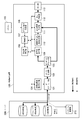
図1は本発明の第1実施形態に係るシステムの構成例を示すブロック図である。本例では、デジタル放送局の配信装置としてのIP(Internet Protocol)放送サーバ(以下、単にサーバという)と、映像処理装置としての映像表示装置を示す。
まず多視点映像データをサーバ200から取得するブロックについて説明する。映像表示装置100は、そのIPインターフェース部101がデジタル放送局の多視点映像データを提供するサーバ200に対し、TCP/IPプロトコルを使ってインターネット経由で接続される。図1にはサーバ200が配信する多視点映像データのうち、3つの視点映像データを代表して示す。IPインターフェース部101はサーバ200からデータを受信して復号化し、IP・TS(トランスポートストリーム)処理部102に出力する。またIPインターフェース部101はサーバ200への要求を出力する。
[First Embodiment]
FIG. 1 is a block diagram showing a configuration example of a system according to the first embodiment of the present invention. In this example, an IP (Internet Protocol) broadcast server (hereinafter simply referred to as a server) as a distribution device of a digital broadcasting station and a video display device as a video processing device are shown.
First, a block for acquiring multi-view video data from the server 200 will be described. The video display apparatus 100 is connected to the server 200 whose
IP・TS処理部102は暗号化されたTS信号を取り出し、暗号化を解除した信号をIP・MPEGデコード部103に出力する。MPEGは"Moving Picture Experts Group"の略号である。IP・MPEGデコード部103は圧縮された映像データを伸長し、これを被写体選択用の映像データとして被写体抽出部109に出力する。IP・MPEGデコード部103は出力映像生成部111にも伸長後の映像データを出力する。
The IP /
次に、被写体の選択及び追尾のために画面切り出し範囲を決定するブロックについて説明する。リモートコンローラ(以下、リモコンという)105はユーザが映像表示装置100への操作指示を送信する際に使用する。ユーザがリモコン105を使用して被写体を選択する際、リモコン105からの信号をリモコン信号受信部106が受信して操作指示信号を制御部107に出力する。制御部107は、ユーザの操作指示を受けて被写体を決定し、被写体選択部108は、複数の被写体から選択された被写体の情報(被写体情報)を保持する。被写体情報は画面切り出し範囲決定部(以下、範囲決定部という)110に送られ、範囲決定部110は被写体情報に基づいて画面切り出し範囲を決定する。画面切り出し範囲の情報は出力映像生成部111に送信される。ここではIP・MPEGデコード部103から送られてきた映像データの一部を、切り出し範囲情報に基づいて抽出する処理が行われ、処理後の映像信号が出力処理部112に送出される。出力処理部112の出力する映像信号は表示部113に送られて映像が表示される。
Next, a block for determining a screen cutout range for subject selection and tracking will be described. A remote controller (hereinafter referred to as a remote controller) 105 is used when a user transmits an operation instruction to the video display device 100. When the user uses the
制御部107は範囲決定部110からの情報に基づき、多視点映像の選択指示部104を制御する。つまり、映像ソースの切り替えが必要な場合、制御部107は多視点映像の選択指示部104を介してIPインターフェース部101に映像ソースの切り替えを指示する。この指示に従ってIPインターフェース部101は、指示された映像データに変更するために、サーバ200に対して多視点映像の切り替えを要求する。これにより制御部107が選択した映像ソースが提供するデータへの変更制御が行われる。なお各映像ソースは、撮影範囲の異なるカメラでの撮影により提供される映像データを含む。
The
図2は映像ソースを提供するカメラの配置例を示す。例えば競技場の周囲に、撮影範囲が異なる複数台のカメラが配置されていて、各カメラで撮影した映像が多視点映像として放送局から供給されるものとする。カメラA乃至C(符号201乃至203参照)は、黒点で示す被写体204を撮影すべく、矩形状をした競技場の周囲にて一方の長辺方向に沿って互いに隣接して配置されている。また後述の第2実施形態にて説明するカメラD(符号205参照)は、競技場を挟んでカメラA乃至Cとは反対側でカメラBと対向する場所に配置されている。
FIG. 2 shows an example of the arrangement of cameras that provide video sources. For example, it is assumed that a plurality of cameras having different shooting ranges are arranged around a stadium, and videos shot by each camera are supplied from a broadcasting station as multi-viewpoint videos. Cameras A to C (see
映像表示装置100がIPインターフェース部101からサーバ200に対してカメラAの視点映像(A視点映像)の映像データを要求した場合(図1参照)、サーバ200からカメラA201により撮影された映像データが供給される。同様に、サーバ200に対してカメラB202の視点映像(B視点映像)や、カメラC203の視点映像(C視点映像)を映像表示装置100がサーバ200に要求すれば、各視点映像のデータが供給される。これらの映像を表示部113が表示することで多視点映像システムを実現でき、視聴者に所望の視点映像を提供できる。
When the video display apparatus 100 requests video data of the viewpoint video (A viewpoint video) of the camera A from the
次に図3のフローチャートを用いて、映像表示装置100の動作を説明する。なお、以下の処理は該フローチャートに従って作成されたプログラムを制御部107が解釈して実行することで実現される。まず制御部107は、表示映像に関する映像ソースの選択をユーザに促すために選択画面を表示部113に表示させる(S301)。この場合、表示画面上に選択肢を提示してユーザに選択させるか、あるいは、予め定められた映像ソースを表示してもよいし、放送局側で初めに表示する映像ソースを指定してもよい。次に制御部107はユーザに対し、所望の被写体を選択させる処理を実行する(S302)。ユーザが被写体を選択する方法として、例えば制御部107は、ユーザ操作によって画面の一部を範囲指定させるように制御し、指定された範囲の画像認識によって被写体を特定して該被写体のデータを登録する。あるいはメタデータによって与えられている情報(選手情報等)に基づいて、制御部107は、ユーザに対して所望の被写体を選択させるように制御してもよい。
Next, the operation of the video display apparatus 100 will be described using the flowchart of FIG. The following processing is realized by the
被写体の選択後、被写体抽出部109は選択された被写体の画像データを抽出する。範囲決定部110は、現時点で選択されている映像ソースから提供される映像の一部を切り出して、被写体像が画面中央に表示されるように画面切り出し範囲を設定し(S303)、表示部113に映像を表示する。次の処理で制御部107は被写体が動いたか否かを判定する(S304)。その結果、被写体が動いたと判定された場合、S305に進むが、被写体に動きがないと判定された場合にはS304の判定処理が繰り返される。
After selecting a subject, the
次に制御部107は現時点の映像ソースにて被写体像を画面中央で表示可能か否かを判定する(S305)。被写体像を画面中央で表示可能であると判定された場合(YESに分岐)、S303に戻り、範囲決定部110は、画面切り出し範囲を変更する。図4は、カメラA201を用いて被写体204を撮影した映像ソースの映像を使用する場合にカメラ位置と画面切り出し範囲401、撮影範囲402を示す。なお撮影範囲402は映像ソースの提供する映像データに基づいて算出及び判定可能であり、または当該範囲を示す情報をサーバ200から取得可能である。各カメラの撮影範囲は、例えば、カメラの座標位置と、カメラの撮影方向と、カメラの画角(撮影範囲の角度)によって定められる。表示部113の表示範囲に対応する画面切り出し範囲401は被写体204を画面中央に含むように設定される。被写体204の移動により被写体の位置がカメラA201の撮影範囲402を超えてしまい、画面中央に被写体像を表示できなくなった場合、被写体像を画面中央に表示できるように映像ソースの切り替えが必要である。この時の映像ソースの選択処理を以下に説明する。
Next, the
例えば、選択していたカメラA201による映像ソースでは、被写体像を画面中央に表示し得なくなった場合(S305にてNOに分岐)、制御部107は別の映像ソースを検索する処理を行う。つまり被写体像を画面中央で表示可能な映像ソースが検索される。変更前と同じ範囲で画面切り出しが可能な映像ソースの検索方法としては、映像から画像認識で行う方法や、画面切り出し時の座標データに基づいて同じ範囲で画面切り出しが可能な映像ソースを検索する方法がある。また各映像ソースのカメラ位置情報と画角情報を取得し、両情報に基づいて画面切り出しが可能な範囲を計算で求める方法でもよい。
For example, if the subject image cannot be displayed at the center of the screen in the selected video source by the camera A 201 (branch to NO in S305), the
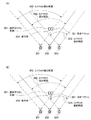
図5(A)は、被写体204を含む画面切り出し範囲501がカメラAの撮影範囲402の外に移動する時点で次に切り替えるべき映像ソースの選択処理を説明する図である。画面切り出し範囲501は、被写体204を画面中央に表示可能な範囲を示し、当該範囲の映像を提供可能な次の映像ソースは、カメラB202で撮影した映像ソースである。つまり画面切り出し範囲501はカメラB202の撮影範囲502内であって、カメラC203の撮影範囲503の外である。図3のS307にて制御部107は、被写体像を画面中央に表示可能な画面切り出し範囲を撮影範囲内に含む映像ソースの数を算出して、その数が2以上であるか否かを判定する。図5(A)にて被写体204がカメラA201の撮影範囲402の外に出た直後において、前記映像ソースの数は1であり、NOの方向へ進む。ここで当該映像ソース、つまりカメラB202で撮影した映像を供給する映像ソースが選択され(S310)、S311に進む。
FIG. 5A is a diagram for explaining a video source selection process to be switched next when the screen cutout range 501 including the subject 204 moves outside the shooting range 402 of the camera A. The screen cutout range 501 indicates a range in which the subject 204 can be displayed at the center of the screen, and the next video source capable of providing video in the range is a video source shot by the camera B202. That is, the screen cutout range 501 is within the shooting range 502 of the camera B202 and outside the shooting range 503 of the camera C203. In S307 of FIG. 3, the
一方、S307にて、被写体像を画面中央に表示可能な画面切り出し範囲を撮影範囲内に含む映像ソースの数が2以上の場合、S308に進む。図5(B)は、被写体204を含む画面切り出し範囲601が、カメラB202の撮影範囲502内であって、かつカメラC203の撮影範囲503内である例を示す。被写体204を画面中央に含む映像については、カメラB、Cによる各映像ソースで表示可能である。この場合、制御部107は映像ソースの切り替え回数が極力少なくなるように映像ソースを選択する。具体的には図3のS308にて制御部107は被写体の動き予測処理を行い、動きベクトルを算出する。次に制御部107は、算出した動きベクトルの方向及び大きさに基づいて、表示可能時間が最も長い映像ソースを選択する(S309)。動きベクトルの算出処理については、被写体の移動軌跡をメモリに記憶しておき、このデータに基づいて算出するか、被写体の座標情報の他、移動方向や移動速度等の情報がメタデータとして与えられる場合に、当該データを用いて算出可能である。また「表示可能時間」は、画面切り出し範囲が各カメラの撮影範囲内に滞留可能な時間を、動きベクトルに基づいて予測することで算出可能である。
On the other hand, in S307, when the number of video sources including a screen cutout range in which the subject image can be displayed in the center of the screen is 2 or more, the process proceeds to S308. FIG. 5B shows an example in which the screen cutout range 601 including the subject 204 is within the shooting range 502 of the camera B202 and within the shooting range 503 of the camera C203. An image including the subject 204 in the center of the screen can be displayed with each image source by the cameras B and C. In this case, the
図6は、動きベクトルに基づく映像ソースの判定処理例を説明する図である。図6(A)の例では、矢印で示すように動きベクトル701が図の右方を向いており、制御部107は、その方向に被写体204が動いた場合、先に画面切り出し処理が出来なくなる映像ソースを判断する。動きベクトル701の方向に被写体204が移動し続けたとすると、先に画面切り出し処理が不可能になるのは、カメラB202による映像ソースである。カメラC203による映像ソースを用いる方がより長い時間、被写体像を表示し続けることができる。そのため、映像ソースの切り替え頻度を低減し、より長く映像を映すことが可能なカメラC203で撮影した映像を供給する映像ソースが選択されることになる。
FIG. 6 is a diagram illustrating an example of a video source determination process based on a motion vector. In the example of FIG. 6A, the motion vector 701 is directed to the right as shown by the arrow, and the
図6(B)は、動きベクトル801が図の下方を向いている場合を例示する。被写体204を画像中央にて長時間に亘って表示し続けることが可能な映像ソースは、カメラC203ではなくカメラB202で撮影したものである。よって、この場合、カメラB202で撮影した映像を供給する映像ソースが選択される。
図3のS309又はS310の後、S311に進む。ここで制御部107は多視点映像の選択指示部104を介してIPインターフェース部101に対し、前記ステップS309又はS310で選択した映像ソースへの切り替えを指示する。IPインターフェース部101は当該映像ソースの映像に切り替える。
第1実施形態によれば、映像ソースの切り替え回数を最小限に抑えつつ、所望の被写体を追尾できる。
FIG. 6B illustrates a case where the motion vector 801 is directed downward in the drawing. A video source capable of continuing to display the subject 204 at the center of the image for a long time is one that was captured by the camera B202 instead of the camera C203. Therefore, in this case, the video source that supplies the video shot by the
After S309 or S310 in FIG. 3, the process proceeds to S311. Here, the
According to the first embodiment, it is possible to track a desired subject while minimizing the number of times of switching video sources.
[第2実施形態]
次に本発明の第2実施形態を説明する。なお第2実施形態に係る装置の構成は第1実施形態の場合と同様であるため、以下では相違点を主に説明する。
図7は、カメラA乃至Cとは反対側にカメラD(符号205参照)を配置した場合の映像ソース選択処理を説明する図である。図中の撮影範囲901はカメラD205が撮影する範囲を示す。
[Second Embodiment]
Next, a second embodiment of the present invention will be described. Since the configuration of the apparatus according to the second embodiment is the same as that of the first embodiment, the differences will be mainly described below.
FIG. 7 is a diagram for explaining video source selection processing when the camera D (see reference numeral 205) is arranged on the side opposite to the cameras A to C. A shooting range 901 in the figure indicates a range shot by the camera D205.
図7(A)は最初にカメラA201から供給される映像を使用していた場合を例示する。ここで被写体204が動きベクトル801に示す方向(図の下方)に移動したため、カメラA201による映像ソースでは、画面切り出し範囲601の映像が供給できなくなった状況を想定する。この場合、第1実施形態と同様に映像ソースの切り替えを必要とするが、動きベクトル801の方向から分かるように、最長時間に亘って被写体204の映像を表示可能な映像ソースは、カメラB202とカメラD205によるものである。しかし、カメラA201の映像からカメラD205の映像に切り替わると、それまでの映像と比べて、被写体像の移動の向きが反対になってしまう。このような映像の切り替えが自動で行われると、視聴者には被写体像の移動方向が分かり難くなり、視聴の妨げとなる可能性がある。そこで制御部107は、被写体の移動の向きが変わってしまう映像ソースに対して選択時の優先度を下げる。図7(A)の例で優先順位を1乃至3で表すと、優先度1はカメラB202で撮影した映像であり、優先度2はカメラC203で撮影した映像、優先度3はカメラD205で撮影した映像となる。
FIG. 7A illustrates a case where the video supplied from the
図7(B)は、カメラB202が存在しない場合を例示する。被写体204が、動きベクトル801を示す矢印の向きに移動した場合、カメラA201による映像ソースからカメラC203による映像ソースに切り替わる。すなわち被写体204の画像を画面中央にて、より長時間表示可能なカメラD205の映像は優先順位が低いために選択されず、画面上で被写体像の移動の向きが変わらないカメラC203で撮影した映像が優先的に選択されて表示される。 FIG. 7B illustrates a case where the camera B202 does not exist. When the subject 204 moves in the direction of the arrow indicating the motion vector 801, the video source from the camera A201 is switched to the video source from the camera C203. That is, the video of the camera D205 that can display the image of the subject 204 in the center of the screen for a longer time is not selected because the priority is low, and the video shot by the camera C203 that does not change the direction of movement of the subject image on the screen. Is preferentially selected and displayed.
第2実施形態によれば、変更前の映像ソースにおける被写体の移動方向と、変更後の映像ソースにおける被写体の移動方向が変化しないか、又は変化量が小さくなるように映像ソースの選択制御が行われる。これにより視聴者にとって違和感の少ない映像ソースの切り替えを実現できる。 According to the second embodiment, the video source selection control is performed so that the moving direction of the subject in the video source before the change and the moving direction of the subject in the video source after the change do not change or the amount of change becomes small. Is called. As a result, it is possible to realize switching of the video source with less discomfort for the viewer.
[第3実施形態]
次に本発明の第3実施形態を説明する。本実施形態では、映像データの供給元である送信装置から受信装置に対し、選択すべき映像ソースを指定する処理例を示す。なお第3実施形態に係る装置の構成は第1実施形態の場合と同様であるため、以下では相違点を主に説明する。本実施形態においても映像ソースの選択基準については前記実施形態の場合と同じであるが、判断主体が映像表示装置100の制御部107ではなく、配信装置の制御部である点で相違する。図1にて映像表示装置100はユーザ操作に従って選択された被写体の情報をサーバ200に通知する。サーバ200のシステム制御部210は、使用すべき映像ソースの映像データ及び表示範囲に対応する画面切り出し範囲の指示情報を映像表示装置100に送信する際の送信制御機能を有する。映像表示装置100はそれらの情報に基づいて映像ソースの切り替えと表示を行う。
[Third Embodiment]
Next, a third embodiment of the present invention will be described. In the present embodiment, an example of processing for designating a video source to be selected from a transmission device as a video data supply source to a reception device will be described. Since the configuration of the apparatus according to the third embodiment is the same as that of the first embodiment, the differences will be mainly described below. In this embodiment, the video source selection criteria are the same as those in the above embodiment, except that the determination subject is not the
図8のフローチャートを用いて、サーバ200の処理例を説明する。なお、以下の処理はシステム制御部210によって解釈及び実行されるプログラムに従って実現される。S304、S305、S307乃至310の処理はシステム制御部210が行うことを除いて、図3に示す第1実施形態の場合と同様であり、以下では相違点であるS1101乃至S1103、S1110を説明する。
A processing example of the server 200 will be described using the flowchart of FIG. Note that the following processing is realized according to a program interpreted and executed by the
サーバ200のシステム制御部210は、映像表示装置100に対して映像ソースを指示する(S1101)。システム制御部210は、映像表示装置100から被写体情報を受け取り(S1102)、指定された被写体が画面中央に表示されるように画面切り出し範囲を決定する。そしてシステム制御部210は、被写体像を画面中央に含む画面切り出し範囲を示す指示情報を、映像表示装置100に送信すべく制御する(S1103)。その後、S304の処理(被写体の移動検出)に進み、S305での判定結果がNOの場合、S307以降の処理が実行される。
The
S309又はS310の後、システム制御部210は、選択した映像ソースへの切り替えを映像表示装置100に指示すべく送信制御を行う(S1110)。
次に図9のフローチャートを用いて映像表示装置100の処理例を説明する。なお、以下の処理は制御部107によって解釈及び実行されるプログラムに従って実現される。
前記S1101での映像表示装置100への指示に従い、制御部107は映像ソースの選択を制御する(S1201)。次にユーザの操作指示を受けて被写体の選択処理が行われる(S1202)。被写体の選択方法は第1実施形態の場合と同様である。制御部107は、選択された被写体を示す被写体情報をサーバ200に通知する制御を行う(S1203)。前記S1103での指示に従って、範囲決定部110は画面切り出し範囲を決定し、表示部113は当該範囲の映像を表示する(S1204)。
After S309 or S310, the
Next, a processing example of the video display apparatus 100 will be described using the flowchart of FIG. The following processing is realized according to a program that is interpreted and executed by the
In accordance with the instruction to the video display apparatus 100 in S1101, the
その後、サーバ200のシステム制御部210は、被写体の動き(移動速度)を検出し(図8のS304参照)、被写体が動いたか否かを判定する。図8のS305乃至310を経てS1110に到達すると、サーバ200のシステム制御部210は、選択した映像ソースを映像表示装置100に指示する。映像表示装置100の制御部107はこの指示を受けて、映像ソースの変更について判定する(S1205)。その結果、当該指示が映像ソースの変更指示と判定された場合(YESに分岐)、制御部107は多視点映像の選択指示部104を介してIPインターフェース部101に指示を送る。これにより、指示された映像ソースに変更され(S1206)、S1207に進む。またS1205にて映像ソースの変更指示でないと判定された場合(NOに分岐)、S1207に進む。ここで制御部107は画面切り出し範囲の変更指示があったか否かを判定し、当該範囲の変更指示があればS1208に進む。ここで範囲決定部110は画面切り出し範囲を変更し、表示部113は当該範囲の映像を表示する。そしてS1205に戻る。またS1207にて画面切り出し範囲の変更指示がないと判定された場合にはS1205に戻る。
第3実施形態では、配信装置にて被写体の追尾を行い、映像ソースの選択指示及び画面切り出し範囲の指示を映像表示装置に送る。これにより映像表示装置にて画面切り替えの頻度を最小限に抑えつつ、被写体像を常に画面中央に表示し続けることができる。
Thereafter, the
In the third embodiment, a subject is tracked by a distribution device, and a video source selection instruction and a screen cutout range instruction are sent to the video display device. Thus, the subject image can always be displayed at the center of the screen while the frequency of screen switching is minimized in the video display device.
[その他の実施形態]
また、本発明は、以下の処理を実行することによっても実現される。即ち、上述した実施形態の機能を実現するソフトウェア(プログラム)を、ネットワーク又は各種記憶媒体を介してシステム或いは装置に供給し、そのシステム或いは装置のコンピュータ(またはCPUやMPU等)がプログラムを読み出して実行する処理である。
[Other Embodiments]
The present invention can also be realized by executing the following processing. That is, software (program) that realizes the functions of the above-described embodiments is supplied to a system or apparatus via a network or various storage media, and a computer (or CPU, MPU, or the like) of the system or apparatus reads the program. It is a process to be executed.
100:映像表示装置
101:IPインターフェース部
104:多視点映像の選択指示部
107:制御部
108:被写体選択部
109:被写体抽出部
111:出力映像生成部
DESCRIPTION OF SYMBOLS 100: Image | video display apparatus 101: IP interface part 104: Multi viewpoint video selection instruction | indication part 107: Control part 108: Subject selection part 109: Subject extraction part 111: Output video generation part
Claims (14)
前記映像データから前記所定の被写体を含む一部の範囲を切り出して表示部に出力する出力手段と、
前記所定の被写体の移動を検出して動き予測処理を行い、前記複数の映像データのそれぞれの撮影範囲内に当該移動する被写体が含まれる時間を算出し、算出した時間に基づいて当該被写体を画面に表示すべく前記複数の映像データから1つの映像データを選択する制御を行う制御手段と、を備えることを特徴とする映像処理装置。 A video processing apparatus that processes a plurality of video data with different shooting ranges and tracks a predetermined subject,
An output means for cutting out a part of the range including the predetermined subject from the video data and outputting it to a display unit;
The movement of the predetermined subject is detected and motion prediction processing is performed, a time during which the moving subject is included in each of the shooting ranges of the plurality of video data is calculated, and the subject is displayed on the screen based on the calculated time. Control means for performing control for selecting one video data from the plurality of video data to be displayed on the video processing apparatus.
前記出力手段は、前記外部装置からの指示にしたがって、前記所定の映像データを選択し、前記選択された所定の映像データから前記所定の被写体を含む一部の範囲を切り出すことを特徴とする、請求項1乃至6のいずれか1項に記載の映像処理装置。 An external device that is a supply source of a plurality of video data having different shooting ranges to the video processing device instructs the video processing device to select predetermined video data,
The output means selects the predetermined video data in accordance with an instruction from the external device, and cuts out a partial range including the predetermined subject from the selected predetermined video data . The video processing apparatus according to claim 1.
前記映像処理装置の出力手段が前記映像データから前記所定の被写体を含む一部の範囲を切り出して表示部に出力する出力ステップと、
前記映像処理装置の制御手段が前記所定の被写体の移動を検出して動き予測処理を行い、前記複数の映像データのそれぞれの撮影範囲内に当該移動する被写体が含まれる時間を算出する算出ステップと、
前記映像処理装置の制御手段が前記算出ステップで算出した時間に基づいて前記移動する被写体を画面に表示すべく前記複数の映像データから1つの映像データを選択する選択ステップとを有することを特徴とする映像処理方法。 A video processing method executed by a video processing apparatus that processes a plurality of video data with different shooting ranges and tracks a predetermined subject,
An output step in which the output means of the video processing device cuts out a part of the range including the predetermined subject from the video data and outputs it to the display unit;
A calculating step in which the control means of the video processing device detects movement of the predetermined subject to perform motion prediction processing, and calculates a time during which the moving subject is included in each shooting range of the plurality of video data; ,
And a selection step of selecting one video data from the plurality of video data so that the moving subject is displayed on a screen based on the time calculated in the calculation step by the control means of the video processing device. Video processing method.
前記出力ステップでは前記出力手段が、前記外部装置からの指示にしたがって、前記所定の映像データを選択し、前記選択された所定の映像データから前記所定の被写体を含む一部の範囲を切り出すことを特徴とする、請求項8乃至13のいずれか1項に記載の映像処理方法。
An external device that is a supply source of a plurality of video data having different shooting ranges to the video processing device instructs the video processing device to select predetermined video data,
In the output step, the output means selects the predetermined video data according to an instruction from the external device, and cuts out a partial range including the predetermined subject from the selected predetermined video data. wherein, the image processing method according to any one of claims 8 to 13.
Priority Applications (1)
| Application Number | Priority Date | Filing Date | Title |
|---|---|---|---|
| JP2010043967A JP5495855B2 (en) | 2010-03-01 | 2010-03-01 | Video processing apparatus and video processing method |
Applications Claiming Priority (1)
| Application Number | Priority Date | Filing Date | Title |
|---|---|---|---|
| JP2010043967A JP5495855B2 (en) | 2010-03-01 | 2010-03-01 | Video processing apparatus and video processing method |
Publications (3)
| Publication Number | Publication Date |
|---|---|
| JP2011182160A JP2011182160A (en) | 2011-09-15 |
| JP2011182160A5 JP2011182160A5 (en) | 2013-04-11 |
| JP5495855B2 true JP5495855B2 (en) | 2014-05-21 |
Family
ID=44693208
Family Applications (1)
| Application Number | Title | Priority Date | Filing Date |
|---|---|---|---|
| JP2010043967A Expired - Fee Related JP5495855B2 (en) | 2010-03-01 | 2010-03-01 | Video processing apparatus and video processing method |
Country Status (1)
| Country | Link |
|---|---|
| JP (1) | JP5495855B2 (en) |
Families Citing this family (16)
| Publication number | Priority date | Publication date | Assignee | Title |
|---|---|---|---|---|
| JP5915558B2 (en) * | 2013-01-30 | 2016-05-11 | カシオ計算機株式会社 | Image selection apparatus, image selection method, image distribution system, and program |
| JP5872497B2 (en) * | 2013-02-07 | 2016-03-01 | 日本電信電話株式会社 | Video distribution system and video distribution method |
| JP5968842B2 (en) * | 2013-09-11 | 2016-08-10 | 日本電信電話株式会社 | Image distribution system and image distribution method |
| JP6326892B2 (en) * | 2014-03-20 | 2018-05-23 | 大日本印刷株式会社 | Imaging system, imaging method, image reproducing apparatus, and program |
| JP2018502488A (en) * | 2014-11-18 | 2018-01-25 | ジェイ. ブラフ,アーレン | Apparatus, method and system for visual image array |
| JP6778912B2 (en) * | 2016-02-03 | 2020-11-04 | パナソニックIpマネジメント株式会社 | Video display method and video display device |
| JP6622650B2 (en) * | 2016-05-18 | 2019-12-18 | キヤノン株式会社 | Information processing apparatus, control method therefor, and imaging system |
| JP6534964B2 (en) * | 2016-05-24 | 2019-06-26 | 日本電信電話株式会社 | Video editing method, video editing apparatus and video editing program |
| JP6904673B2 (en) * | 2016-08-08 | 2021-07-21 | キヤノン株式会社 | Image distribution device |
| KR102139106B1 (en) * | 2016-12-16 | 2020-07-29 | 주식회사 케이티 | Apparatus and user device for providing time slice video |
| JP6241802B1 (en) * | 2017-01-20 | 2017-12-06 | パナソニックIpマネジメント株式会社 | Video distribution system, user terminal device, and video distribution method |
| KR102105510B1 (en) * | 2017-08-17 | 2020-04-28 | 주식회사 케이티 | Server, method and user device for providing time slice video |
| JP7258857B2 (en) * | 2017-09-05 | 2023-04-17 | メタ プラットフォームズ, インク. | Modification of video data capture by the imaging device based on video data previously captured by the imaging device |
| US10868955B2 (en) | 2017-09-05 | 2020-12-15 | Facebook, Inc. | Modifying capture of video data by an image capture device based on video data previously captured by the image capture device |
| US11228790B2 (en) | 2018-11-30 | 2022-01-18 | Kt Corporation | Providing time slice video |
| CN111757141B (en) * | 2020-07-22 | 2022-03-11 | 四川新视创伟超高清科技有限公司 | Cloud streaming media picture cutting method |
Family Cites Families (5)
| Publication number | Priority date | Publication date | Assignee | Title |
|---|---|---|---|---|
| JPH05130528A (en) * | 1991-11-05 | 1993-05-25 | Oki Electric Ind Co Ltd | Visual point variable television system |
| JP3615867B2 (en) * | 1996-05-24 | 2005-02-02 | 日本放送協会 | Automatic camera system |
| JP2000032435A (en) * | 1998-07-10 | 2000-01-28 | Mega Chips Corp | Monitoring system |
| CA2309459A1 (en) * | 1999-06-10 | 2000-12-10 | International Business Machines Corporation | System for personalized field of view in a broadcast environment |
| WO2007119355A1 (en) * | 2006-03-15 | 2007-10-25 | Omron Corporation | Tracking device, tracking method, tracking device control program, and computer-readable recording medium |
-
2010
- 2010-03-01 JP JP2010043967A patent/JP5495855B2/en not_active Expired - Fee Related
Also Published As
| Publication number | Publication date |
|---|---|
| JP2011182160A (en) | 2011-09-15 |
Similar Documents
| Publication | Publication Date | Title |
|---|---|---|
| JP5495855B2 (en) | Video processing apparatus and video processing method | |
| US11006089B2 (en) | Information processing apparatus and information processing method | |
| EP3522542B1 (en) | Switching between multidirectional and limited viewport video content | |
| JP6385139B2 (en) | Information processing apparatus, information processing method, and program | |
| US11417062B2 (en) | Information processing device, information processing method, and program | |
| US20180191955A1 (en) | Moving picture reproducing device, moving picture reproducing method, moving picture reproducing program, moving picture reproducing system, and moving picture transmission device | |
| JP2015204512A (en) | Information processing apparatus, information processing method, camera, reception device, and reception method | |
| JP5835932B2 (en) | Image processing apparatus and control method thereof | |
| KR20150006771A (en) | Method and device for rendering selected portions of video in high resolution | |
| CN105939497B (en) | Media streaming system and media streaming method | |
| CN105359504B (en) | Image information processing method and apparatus using camera position order | |
| KR102133207B1 (en) | Communication apparatus, communication control method, and communication system | |
| JP2012142860A (en) | Arbitrary viewpoint video processing device, control method therefor, and program | |
| JP5348114B2 (en) | Information display system, apparatus, method and program | |
| JP2017123503A (en) | Video distribution apparatus, video distribution method and computer program | |
| WO2016167160A1 (en) | Data generation device and reproduction device | |
| JP2020042407A (en) | Information processor and information processing method and program | |
| EP3621309A1 (en) | Transmission system for multi-channel image, control method therefor, and multi-channel image playback method and apparatus | |
| JP2012151688A (en) | Video reproduction device and method of controlling the same, program, and storage medium | |
| JP2012015788A (en) | Video receiver and control method thereof | |
| JP2012004991A (en) | Broadcast receiving apparatus and control method for the same | |
| JP6261191B2 (en) | Display control apparatus, display control method, and program | |
| JP2012034083A (en) | Video processing apparatus and control method of the same | |
| JP2009296536A (en) | Moving image relay distributing device, moving image relay distributing method and program | |
| JP6660622B2 (en) | Information processing device, information processing method, camera, receiving device, receiving method |
Legal Events
| Date | Code | Title | Description |
|---|---|---|---|
| A521 | Written amendment |
Free format text: JAPANESE INTERMEDIATE CODE: A523 Effective date: 20130227 |
|
| A621 | Written request for application examination |
Free format text: JAPANESE INTERMEDIATE CODE: A621 Effective date: 20130227 |
|
| A977 | Report on retrieval |
Free format text: JAPANESE INTERMEDIATE CODE: A971007 Effective date: 20131114 |
|
| A131 | Notification of reasons for refusal |
Free format text: JAPANESE INTERMEDIATE CODE: A131 Effective date: 20131119 |
|
| A521 | Written amendment |
Free format text: JAPANESE INTERMEDIATE CODE: A523 Effective date: 20131216 |
|
| TRDD | Decision of grant or rejection written | ||
| A01 | Written decision to grant a patent or to grant a registration (utility model) |
Free format text: JAPANESE INTERMEDIATE CODE: A01 Effective date: 20140204 |
|
| A61 | First payment of annual fees (during grant procedure) |
Free format text: JAPANESE INTERMEDIATE CODE: A61 Effective date: 20140304 |
|
| R151 | Written notification of patent or utility model registration |
Ref document number: 5495855 Country of ref document: JP Free format text: JAPANESE INTERMEDIATE CODE: R151 |
|
| LAPS | Cancellation because of no payment of annual fees |