JP5484943B2 - Gas turbine premixer with internal cooling - Google Patents
Gas turbine premixer with internal cooling Download PDFInfo
- Publication number
- JP5484943B2 JP5484943B2 JP2010028380A JP2010028380A JP5484943B2 JP 5484943 B2 JP5484943 B2 JP 5484943B2 JP 2010028380 A JP2010028380 A JP 2010028380A JP 2010028380 A JP2010028380 A JP 2010028380A JP 5484943 B2 JP5484943 B2 JP 5484943B2
- Authority
- JP
- Japan
- Prior art keywords
- fuel
- flow path
- central body
- downstream
- upstream
- Prior art date
- Legal status (The legal status is an assumption and is not a legal conclusion. Google has not performed a legal analysis and makes no representation as to the accuracy of the status listed.)
- Expired - Fee Related
Links
- 238000001816 cooling Methods 0.000 title description 50
- 239000000446 fuel Substances 0.000 claims description 222
- 238000011144 upstream manufacturing Methods 0.000 claims description 36
- 238000005192 partition Methods 0.000 claims description 21
- 210000003746 feather Anatomy 0.000 claims 1
- 230000000149 penetrating effect Effects 0.000 claims 1
- 238000000638 solvent extraction Methods 0.000 claims 1
- 239000007789 gas Substances 0.000 description 77
- 238000002347 injection Methods 0.000 description 29
- 239000007924 injection Substances 0.000 description 29
- 230000015572 biosynthetic process Effects 0.000 description 22
- 238000002485 combustion reaction Methods 0.000 description 22
- 238000003786 synthesis reaction Methods 0.000 description 22
- IJGRMHOSHXDMSA-UHFFFAOYSA-N Atomic nitrogen Chemical compound N#N IJGRMHOSHXDMSA-UHFFFAOYSA-N 0.000 description 20
- 239000000203 mixture Substances 0.000 description 17
- MWUXSHHQAYIFBG-UHFFFAOYSA-N Nitric oxide Chemical compound O=[N] MWUXSHHQAYIFBG-UHFFFAOYSA-N 0.000 description 15
- 230000003685 thermal hair damage Effects 0.000 description 15
- 238000002156 mixing Methods 0.000 description 14
- 239000002994 raw material Substances 0.000 description 13
- 239000002826 coolant Substances 0.000 description 12
- 238000000034 method Methods 0.000 description 10
- 229910052757 nitrogen Inorganic materials 0.000 description 10
- 229910002091 carbon monoxide Inorganic materials 0.000 description 8
- 229910052739 hydrogen Inorganic materials 0.000 description 8
- 238000004519 manufacturing process Methods 0.000 description 8
- XLYOFNOQVPJJNP-UHFFFAOYSA-N water Substances O XLYOFNOQVPJJNP-UHFFFAOYSA-N 0.000 description 8
- 238000006243 chemical reaction Methods 0.000 description 7
- 239000001257 hydrogen Substances 0.000 description 7
- 239000000463 material Substances 0.000 description 7
- CURLTUGMZLYLDI-UHFFFAOYSA-N Carbon dioxide Chemical compound O=C=O CURLTUGMZLYLDI-UHFFFAOYSA-N 0.000 description 6
- UGFAIRIUMAVXCW-UHFFFAOYSA-N Carbon monoxide Chemical compound [O+]#[C-] UGFAIRIUMAVXCW-UHFFFAOYSA-N 0.000 description 6
- UFHFLCQGNIYNRP-UHFFFAOYSA-N Hydrogen Chemical compound [H][H] UFHFLCQGNIYNRP-UHFFFAOYSA-N 0.000 description 6
- QVGXLLKOCUKJST-UHFFFAOYSA-N atomic oxygen Chemical compound [O] QVGXLLKOCUKJST-UHFFFAOYSA-N 0.000 description 6
- 238000002309 gasification Methods 0.000 description 6
- VNWKTOKETHGBQD-UHFFFAOYSA-N methane Chemical compound C VNWKTOKETHGBQD-UHFFFAOYSA-N 0.000 description 6
- 239000001301 oxygen Substances 0.000 description 6
- 229910052760 oxygen Inorganic materials 0.000 description 6
- 230000008569 process Effects 0.000 description 6
- 239000000567 combustion gas Substances 0.000 description 5
- 238000009826 distribution Methods 0.000 description 5
- QGZKDVFQNNGYKY-UHFFFAOYSA-N Ammonia Chemical compound N QGZKDVFQNNGYKY-UHFFFAOYSA-N 0.000 description 4
- NINIDFKCEFEMDL-UHFFFAOYSA-N Sulfur Chemical compound [S] NINIDFKCEFEMDL-UHFFFAOYSA-N 0.000 description 4
- 230000006378 damage Effects 0.000 description 4
- 230000002093 peripheral effect Effects 0.000 description 4
- 238000002360 preparation method Methods 0.000 description 4
- 238000000746 purification Methods 0.000 description 4
- 229910052717 sulfur Inorganic materials 0.000 description 4
- 239000011593 sulfur Substances 0.000 description 4
- OKKJLVBELUTLKV-UHFFFAOYSA-N Methanol Chemical compound OC OKKJLVBELUTLKV-UHFFFAOYSA-N 0.000 description 3
- 230000008901 benefit Effects 0.000 description 3
- 229910002092 carbon dioxide Inorganic materials 0.000 description 3
- 239000001569 carbon dioxide Substances 0.000 description 3
- 239000007788 liquid Substances 0.000 description 3
- 238000010248 power generation Methods 0.000 description 3
- 238000000197 pyrolysis Methods 0.000 description 3
- 238000012546 transfer Methods 0.000 description 3
- 229910021529 ammonia Inorganic materials 0.000 description 2
- 230000004323 axial length Effects 0.000 description 2
- 230000008859 change Effects 0.000 description 2
- 239000012809 cooling fluid Substances 0.000 description 2
- 230000007423 decrease Effects 0.000 description 2
- 238000013461 design Methods 0.000 description 2
- 238000010586 diagram Methods 0.000 description 2
- 239000003085 diluting agent Substances 0.000 description 2
- 238000005516 engineering process Methods 0.000 description 2
- 239000012530 fluid Substances 0.000 description 2
- 238000010438 heat treatment Methods 0.000 description 2
- 229910052751 metal Inorganic materials 0.000 description 2
- 239000002184 metal Substances 0.000 description 2
- 150000003839 salts Chemical class 0.000 description 2
- 239000002893 slag Substances 0.000 description 2
- 239000007787 solid Substances 0.000 description 2
- 239000000126 substance Substances 0.000 description 2
- 239000002028 Biomass Substances 0.000 description 1
- OKTJSMMVPCPJKN-UHFFFAOYSA-N Carbon Chemical compound [C] OKTJSMMVPCPJKN-UHFFFAOYSA-N 0.000 description 1
- VYZAMTAEIAYCRO-UHFFFAOYSA-N Chromium Chemical compound [Cr] VYZAMTAEIAYCRO-UHFFFAOYSA-N 0.000 description 1
- 229910000831 Steel Inorganic materials 0.000 description 1
- 239000002253 acid Substances 0.000 description 1
- 239000002154 agricultural waste Substances 0.000 description 1
- 239000000956 alloy Substances 0.000 description 1
- 229910045601 alloy Inorganic materials 0.000 description 1
- WYTGDNHDOZPMIW-RCBQFDQVSA-N alstonine Natural products C1=CC2=C3C=CC=CC3=NC2=C2N1C[C@H]1[C@H](C)OC=C(C(=O)OC)[C@H]1C2 WYTGDNHDOZPMIW-RCBQFDQVSA-N 0.000 description 1
- 238000000149 argon plasma sintering Methods 0.000 description 1
- 239000010426 asphalt Substances 0.000 description 1
- 238000005219 brazing Methods 0.000 description 1
- 239000004566 building material Substances 0.000 description 1
- 229910052799 carbon Inorganic materials 0.000 description 1
- 238000005266 casting Methods 0.000 description 1
- 229910052804 chromium Inorganic materials 0.000 description 1
- 239000011651 chromium Substances 0.000 description 1
- 239000003245 coal Substances 0.000 description 1
- 229910017052 cobalt Inorganic materials 0.000 description 1
- 239000010941 cobalt Substances 0.000 description 1
- GUTLYIVDDKVIGB-UHFFFAOYSA-N cobalt atom Chemical compound [Co] GUTLYIVDDKVIGB-UHFFFAOYSA-N 0.000 description 1
- 239000000571 coke Substances 0.000 description 1
- 239000002131 composite material Substances 0.000 description 1
- 238000005520 cutting process Methods 0.000 description 1
- 230000003247 decreasing effect Effects 0.000 description 1
- 238000011161 development Methods 0.000 description 1
- 230000018109 developmental process Effects 0.000 description 1
- 238000004821 distillation Methods 0.000 description 1
- 230000000694 effects Effects 0.000 description 1
- 238000000227 grinding Methods 0.000 description 1
- 239000013529 heat transfer fluid Substances 0.000 description 1
- 150000002431 hydrogen Chemical class 0.000 description 1
- 230000001939 inductive effect Effects 0.000 description 1
- 238000009413 insulation Methods 0.000 description 1
- 238000003801 milling Methods 0.000 description 1
- 239000003345 natural gas Substances 0.000 description 1
- 238000005453 pelletization Methods 0.000 description 1
- 239000002006 petroleum coke Substances 0.000 description 1
- 238000012545 processing Methods 0.000 description 1
- 238000011084 recovery Methods 0.000 description 1
- 230000000246 remedial effect Effects 0.000 description 1
- 238000007789 sealing Methods 0.000 description 1
- 238000000926 separation method Methods 0.000 description 1
- 239000002002 slurry Substances 0.000 description 1
- 239000011343 solid material Substances 0.000 description 1
- 239000004449 solid propellant Substances 0.000 description 1
- 230000000087 stabilizing effect Effects 0.000 description 1
- 239000010959 steel Substances 0.000 description 1
- 239000011269 tar Substances 0.000 description 1
- 238000005979 thermal decomposition reaction Methods 0.000 description 1
- 239000002912 waste gas Substances 0.000 description 1
- 239000002699 waste material Substances 0.000 description 1
- 238000003466 welding Methods 0.000 description 1
- 239000002023 wood Substances 0.000 description 1
Images


Classifications
-
- F—MECHANICAL ENGINEERING; LIGHTING; HEATING; WEAPONS; BLASTING
- F23—COMBUSTION APPARATUS; COMBUSTION PROCESSES
- F23R—GENERATING COMBUSTION PRODUCTS OF HIGH PRESSURE OR HIGH VELOCITY, e.g. GAS-TURBINE COMBUSTION CHAMBERS
- F23R3/00—Continuous combustion chambers using liquid or gaseous fuel
- F23R3/28—Continuous combustion chambers using liquid or gaseous fuel characterised by the fuel supply
- F23R3/286—Continuous combustion chambers using liquid or gaseous fuel characterised by the fuel supply having fuel-air premixing devices
-
- F—MECHANICAL ENGINEERING; LIGHTING; HEATING; WEAPONS; BLASTING
- F23—COMBUSTION APPARATUS; COMBUSTION PROCESSES
- F23R—GENERATING COMBUSTION PRODUCTS OF HIGH PRESSURE OR HIGH VELOCITY, e.g. GAS-TURBINE COMBUSTION CHAMBERS
- F23R3/00—Continuous combustion chambers using liquid or gaseous fuel
- F23R3/02—Continuous combustion chambers using liquid or gaseous fuel characterised by the air-flow or gas-flow configuration
- F23R3/04—Air inlet arrangements
- F23R3/10—Air inlet arrangements for primary air
- F23R3/12—Air inlet arrangements for primary air inducing a vortex
- F23R3/14—Air inlet arrangements for primary air inducing a vortex by using swirl vanes
-
- F—MECHANICAL ENGINEERING; LIGHTING; HEATING; WEAPONS; BLASTING
- F23—COMBUSTION APPARATUS; COMBUSTION PROCESSES
- F23R—GENERATING COMBUSTION PRODUCTS OF HIGH PRESSURE OR HIGH VELOCITY, e.g. GAS-TURBINE COMBUSTION CHAMBERS
- F23R3/00—Continuous combustion chambers using liquid or gaseous fuel
- F23R3/28—Continuous combustion chambers using liquid or gaseous fuel characterised by the fuel supply
- F23R3/283—Attaching or cooling of fuel injecting means including supports for fuel injectors, stems, or lances
Description
本発明は、ガスタービンエンジンの燃焼器における燃焼のために燃料と空気とを予混合するように構成されたガスタービン予混合器に関する。特に、本発明は、ガスタービン予混合器の冷却システムに関する。 The present invention relates to a gas turbine premixer configured to premix fuel and air for combustion in a combustor of a gas turbine engine. In particular, the present invention relates to a cooling system for a gas turbine premixer.
ガスタービンエンジンは、燃料と空気の混合物を燃焼して高温燃焼ガスを発生する。高温燃焼ガスは1つ以上のタービンを駆動する。特に、高温燃焼ガスはタービン翼を強制回転させ、それにより軸を駆動して、1つ以上の負荷、例えば発電機を回転させる。燃料と空気の可燃性混合物を含む燃焼ゾーンにおいて、炎が発生することは知られている。反応ゾーンにごく近接するようには設計されていない表面又はその付近に炎が発生する望ましくない状況が時折起こり、その結果、燃焼の熱による損傷が発生する。燃料/空気予混合器におけるこの現象は、一般に保炎と呼ばれる。例えば、保炎は燃料‐空気予混合器又はその付近で起こり、燃焼の熱によって予混合器の障害が急速に起こる。同様に、燃焼ゾーンから上流側へ炎が広がる場合もあり、燃焼の熱によって種々の構成要素が損傷される。この現象は一般に逆火と呼ばれる。 A gas turbine engine burns a mixture of fuel and air to generate hot combustion gases. The hot combustion gases drive one or more turbines. In particular, the hot combustion gases force the turbine blades to rotate, thereby driving the shaft and rotating one or more loads, such as a generator. It is known that a flame is generated in a combustion zone containing a combustible mixture of fuel and air. Occasionally, an undesirable situation occurs in which a flame develops at or near a surface that is not designed to be in close proximity to the reaction zone, resulting in thermal damage from combustion. This phenomenon in a fuel / air premixer is commonly referred to as flame holding. For example, flame holding occurs at or near the fuel-air premixer, and preheater failure occurs rapidly due to the heat of combustion. Similarly, flames may spread upstream from the combustion zone, and various components are damaged by the heat of combustion. This phenomenon is generally called flashback.
ガスタービン予混合器の冷却システムを提供する。 A cooling system for a gas turbine premixer is provided.
当初特許請求された発明の範囲に相応する範囲内のある特定の実施形態を以下に要約する。それらの実施形態は、特許請求された発明の範囲を限定することを意図せず、本発明の可能な形態を簡単に要約することのみを意図する。実際、本発明は、以下に記載される実施形態に類似する又はそれらとは異なる多様な形態を包含してもよい。 Certain specific embodiments within the scope corresponding to the scope of the originally claimed invention are summarized below. These embodiments are not intended to limit the scope of the claimed invention, but are merely intended to briefly summarize possible forms of the invention. Indeed, the invention may encompass a variety of forms that may be similar to or different from the embodiments set forth below.
第1の実施形態において、システムは、中央本体と、中央本体の周囲に配設された外側管と、中央本体と外側管との間に設けられた空気流路と、空気流路に配設され、燃料入口、燃料出口及び燃料入口と燃料出口との間に配設された仕切りを具備する羽根と、中央本体を通って羽根の燃料入口まで延出し、仕切りに沿って燃料入口から燃料出口まで非直線方向に羽根を通って延出する燃料流路とを具備する燃料ノズルを含む。 In the first embodiment, the system includes a central body, an outer pipe disposed around the central body, an air flow path provided between the central main body and the outer pipe, and the air flow path. A vane having a fuel inlet, a fuel outlet and a partition disposed between the fuel inlet and the fuel outlet, and extending through the central body to the fuel inlet of the vane and from the fuel inlet to the fuel outlet along the partition A fuel nozzle having a fuel flow path extending through the vanes in a non-linear direction.
第2の実施形態において、ガスタービン燃料ノズルは、第1の軸方向に燃料を搬送するように構成された第1の流路及び第1の軸方向とは逆の第2の軸方向に燃料を搬送するように構成された第2の流路を有する多方向流路を具備する中央本体と、中央本体の周囲に配設された外側管と、中央本体と外側管との間に設けられた空気流路と、空気流路に配設された羽根であって、第1の軸方向に対して羽根の下流側空胴に設けられた燃料入口、第1の軸方向に対して羽根の上流側空胴に設けられた燃料出口、下流側空胴から上流側空胴まで延出する燃料流路及び燃料流路とは無関係に上流側空胴へ燃料を搬送するように構成されたバイパス流路を具備する羽根とを含む。 In the second embodiment, the gas turbine fuel nozzle has a first flow path configured to convey the fuel in the first axial direction and a fuel in the second axial direction opposite to the first axial direction. A central body having a multi-directional flow path having a second flow path configured to convey, an outer tube disposed around the central body, and provided between the central body and the outer tube. An air flow path, and a vane disposed in the air flow path, a fuel inlet provided in a cavity downstream of the vane with respect to the first axial direction, and a vane of the vane with respect to the first axial direction A fuel outlet provided in the upstream cavity, a fuel passage extending from the downstream cavity to the upstream cavity, and a bypass configured to convey fuel to the upstream cavity independently of the fuel passage And a blade having a flow path.
第3の実施形態において、システムは、燃料及び空気を下流側方向に旋回させるように構成された旋回羽根を有する空気‐燃料予混合器を具備し、旋回羽根は、下流側端部から上流側方向へ旋回羽根の長さにほぼ沿って延出する内部冷却流路を具備するタービン燃料ノズルを含む。 In a third embodiment, the system comprises an air-fuel premixer having swirl vanes configured to swirl fuel and air in a downstream direction, the swirl vanes upstream from the downstream end. A turbine fuel nozzle having an internal cooling passage extending in a direction substantially along the length of the swirl vane.
本発明の上記の特徴、態様及び利点並びに他の特徴、面及び利点は、添付の図面を参照して以下の詳細な説明を読むことにより更によく理解されるであろう。図面中、同じ図中符号は一貫して同じ部分を示す。
以下に、本発明の1つ以上の特定の実施形態を説明する。それらの実施形態を簡潔に説明しようとする中で、実際の実現形態の全ての特徴が本明細書で説明されない場合もある。そのような実際の任意の実現形態を生産技術又は設計プロジェクトにおいて開発する際には、実現形態ごとに異なると思われるシステムに関連する制約及び業務に関連する制約に従うなどの開発担当者別の目標を達成するために、その実現形態に特定された多くの決定を下さなければならないことを理解すべきである。更に、そのような開発の努力は複雑で長時間を要するであろうが、本開示の知識を得た当業者にとって、それは日常的な設計、製作及び製造の作業であると考えられることも理解すべきである。 The following describes one or more specific embodiments of the present invention. In an effort to briefly describe those embodiments, not all features of an actual implementation may be described in the specification. When developing such an actual realization in a production technology or design project, the goals for each developer, such as obeying system-related and business-related constraints that are likely to be different for each realization It should be understood that many decisions specific to the implementation must be made in order to achieve Further, although such development efforts will be complex and time consuming, it will also be understood by those skilled in the art who are knowledgeable of the present disclosure that they are considered routine design, fabrication and manufacturing operations. Should.
本発明の種々の実施形態の要素が単数形で説明される場合、単数形は、それらの要素が1つ以上存在することを意味することを意図する。用語「具備する」、「含む」及び「有する」は、そこに挙げられている要素を含めてという意味であり、それらの要素以外に追加の要素が存在してもよいことを意図する。 Where elements of various embodiments of the invention are described in the singular, the singular is intended to mean that there are one or more of those elements. The terms “comprising”, “including”, and “having” mean including the elements listed therein, and are intended to include additional elements in addition to those elements.
ある特定の実施形態において、以下に詳細に説明されるように、ガスタービンエンジンは、逆火及び/又は保炎と関連する熱損傷に耐えるために内部冷却流路を有する1つ以上の燃料ノズルを含む。特に、燃料ノズルは、燃料‐空気予混合器の中に1つ以上の内部冷却流路、例えば燃料及び空気が燃焼ゾーンに流入する前に燃料と空気との混合を容易にするように構成された旋回羽根を含んでもよい。例えば、燃料ノズルは、周囲に沿って配列された複数の旋回羽根を含んでもよく、内部冷却流路は旋回羽根の軸方向の全長にほぼ沿って延出する。ある特定の実施形態において、各内部冷却流路は、それぞれ対応する旋回羽根の下流側端部から上流側端部まで冷却剤を送り出すことにより、下流側端部における冷却が最大になるようにしてもよい。例えば、冷却剤は燃料であってもよく、その場合、燃料は下流側端部から上流側端部まで旋回羽根を貫流してもよい。上流側端部において、燃料は1つ以上の燃料ポートを通って旋回羽根から流出してもよい。燃料ポートは、燃料‐空気混合物を形成するために空気流れの中へ燃料を送り込む。従って、燃料流れは2つの機能を果たし、燃焼のための燃料供給源として作用するのみならず、空気流れの中へ噴射される前に旋回羽根から熱を伝達するための熱交換媒体としても作用する。 In certain embodiments, as will be described in detail below, a gas turbine engine may include one or more fuel nozzles having internal cooling channels to withstand thermal damage associated with flashback and / or flame holding. including. In particular, the fuel nozzle is configured to facilitate mixing of the fuel and air in the fuel-air premixer, such as one or more internal cooling channels, for example, before the fuel and air enter the combustion zone. Swirl vanes may also be included. For example, the fuel nozzle may include a plurality of swirl vanes arranged along the periphery, and the internal cooling channel extends substantially along the entire axial length of the swirl vanes. In certain embodiments, each internal cooling channel is configured to deliver maximum cooling at the downstream end by delivering coolant from the downstream end of the corresponding swirl vane to the upstream end. Also good. For example, the coolant may be fuel, in which case the fuel may flow through the swirl vanes from the downstream end to the upstream end. At the upstream end, fuel may exit the swirl vane through one or more fuel ports. The fuel port pumps fuel into the air stream to form a fuel-air mixture. Thus, the fuel stream serves two functions, not only acting as a fuel source for combustion, but also acting as a heat exchange medium for transferring heat from the swirl vanes before being injected into the air stream. To do.
ある特定の実施形態において、各内部冷却流路は、下流側端部で燃料流れの第1の部分を受け取り、上流側端部で燃料流れの第2の部分を更に受け取ってもよい。換言すれば、燃料流れの第2の部分はバイパス流れと説明されてもよく、このバイパス流れは旋回羽根の軸方向全長に沿って下流側端部から上流側端部まで流れるのではない。従って、システムは、燃料系統の圧力降下、対流熱伝達係数及び燃料ポートへの燃料の配分を調整するために燃料流れの第1の部分及び第2の部分を制御してもよい。 In certain embodiments, each internal cooling flow path may receive a first portion of fuel flow at the downstream end and further receive a second portion of fuel flow at the upstream end. In other words, the second portion of the fuel flow may be described as a bypass flow, which does not flow from the downstream end to the upstream end along the entire axial length of the swirl vane. Thus, the system may control the first and second portions of the fuel flow to adjust the fuel system pressure drop, convective heat transfer coefficient, and fuel distribution to the fuel ports.
保炎又は逆火が起こった場合、内部冷却流路は、その状況を検出し且つ改善するのに十分な時間の間熱損傷に対する熱抵抗を与えるか又は熱絶縁を実現するか、あるいは熱損傷から各要素を保護する。例えば、内部冷却流路は、少なくとも約15秒、30秒、45秒、60秒、75秒又は90秒を超える時間、あるいは更に長時間にわたり熱保護を実行してもよい。更に、内部冷却流路は、冷却剤又は熱交換媒体として燃料を使用して、熱損傷の場合の内蔵フェールセーフとして機能する。特に、熱損傷は旋回羽根の下流側端部(例えば先端)で起こり、それにより、燃料を内部冷却流路から空気流れの中へ直接流入させてもよい。その結果、燃料流れは、旋回羽根の上流側端部の燃料ポートからほぼ又は完全に迂回して流れるようになるので、上流側の燃料‐空気混合物が旋回羽根の下流側端部(例えば先端)における熱損傷の影響を受ける事態はほぼ又は完全に回避される。従って、旋回羽根の下流側端部(例えば開いた先端)における熱損傷は、燃料ノズルに対する更なる損傷(例えば更に上流側)の危険を低減又は排除する。 When flame holding or flashback occurs, the internal cooling flow path provides thermal resistance to thermal damage or provides thermal insulation for a time sufficient to detect and improve the situation, or thermal damage Protect each element from. For example, the internal cooling channel may perform thermal protection for at least about 15 seconds, 30 seconds, 45 seconds, 60 seconds, 75 seconds or more than 90 seconds, or even longer. In addition, the internal cooling channel functions as a built-in failsafe in case of thermal damage using fuel as a coolant or heat exchange medium. In particular, thermal damage may occur at the downstream end (eg, tip) of the swirl vane, thereby allowing fuel to flow directly into the air stream from the internal cooling channel. As a result, the fuel flow flows almost or completely around the fuel port at the upstream end of the swirl vane, so that the upstream fuel-air mixture is at the downstream end (eg, tip) of the swirl vane. The situation of being affected by thermal damage is almost or completely avoided. Thus, thermal damage at the downstream end (eg, open tip) of the swirl vanes reduces or eliminates the risk of further damage (eg, further upstream) to the fuel nozzle.
図1は、合成ガスを発生し且つ燃焼してもよい統合ガス化複合サイクル(IGCC)システム100の一実施形態を示した図である。IGCCシステム100の要素は、IGCCのエネルギー供給源として利用されてもよい固体原料などの燃料供給源102を含んでもよい。燃料供給源102は石炭、石油コークス、バイオマス、木材原料、農業廃棄物、タール、コークス炉ガス及びアスファルト、又は他の炭素含有品目を含んでもよい。
FIG. 1 is a diagram illustrating one embodiment of an integrated gasification combined cycle (IGCC)
燃料供給源102の固体燃料は、原料準備装置104に供給されてもよい。固体原料を製造するために、原料準備装置104は、例えば切断、ミリング、細断、粉砕、ブリケット化又はペレット化により燃料供給源102の原料の大きさ又は形状を変えてもよい。更に、スラリ原料を製造するために、原料準備装置104において燃料供給源102の原料に水又は他の適切な液体が添加されてもよい。他の実施形態において、乾燥原料を製造するために、燃料供給源の原料には液体は添加されない。
The solid fuel from the
原料は原料準備装置104からガス化装置106に供給されてもよい。ガス化装置106は原料を合成ガス、例えば一酸化炭素と水素の混合物に変換してもよい。利用されるガス化装置106の種類に応じて例えば約20バール〜85バールの高圧及び例えば約700℃〜約1,600℃の温度の制御された量の蒸気及び酸素に原料をさらすことにより、この変換が実行されてもよい。ガス化処理は、原料が熱分解を受けることにより原料が加熱されることを含んでもよい。原料を製造するために利用される燃料供給源102に応じて、熱分解処理中のガス化装置106内部の温度は約150℃〜700℃の範囲であってもよい。熱分解処理中の原料の加熱により、固体(例えばチャー)及び残渣ガス(例えば一酸化炭素、水素及び窒素)が生成されてもよい。原料の熱分解処理により残留したチャーの重量は、元の原料の重量のわずか約30%であってもよい。
The raw material may be supplied from the raw
その後、ガス化装置106において燃焼処理が実行されてもよい。燃焼はチャー及び残渣ガスに酸素を導入することを含んでもよい。チャー及び残渣ガスは酸素と反応して、二酸化炭素及び一酸化炭素を形成してもよい。その結果、続くガス化反応に利用される熱が発生する。燃焼処理中の温度は、約700℃〜約1,600℃の範囲であってもよい。次に、ガス化過程の間に、ガス化装置106に蒸気が導入されてもよい。チャーは二酸化炭素及び蒸気と反応して、約800℃〜約1,100℃の範囲の温度の一酸化炭素及び水素を発生してもよい。本質的に、ガス化装置は蒸気及び酸素を利用して原料の一部を「燃焼」させることにより、一酸化炭素を発生し且つエネルギーを放出する。このエネルギーは2回目の反応を促進し、それにより残る原料が水素及び二酸化炭素へと変換される。
Thereafter, a combustion process may be performed in the
このように、ガス化装置106により合成ガスが製造される。この合成ガスは、約85%の一酸化炭素及び水素を等しい割合で含む他に、CH4、HCl、HF、COS、NH3、HCN及びH2S(原料の硫黄含有量によって異なる)を含有する。この合成ガスは例えばH2Sを含むため、汚染合成ガスと呼ばれてもよい。ガス化装置106は、湿潤灰物質であるスラグ108などの廃棄物を生成してもよい。スラグ108はガス化装置106から取り除かれ、例えば基層又は別の建築材料として処分されてもよい。汚染合成ガスを清浄にするために、ガス浄化装置110が利用されてもよい。ガス浄化装置110は、汚染合成ガスからHCl、HF、COS、HCN及びH2Sを除去するために汚染合成ガスを洗浄してもよい。この処理は、例えば硫黄処理装置112における酸性ガス除去処理により硫黄111を分離することを含んでもよい。更に、ガス浄化装置110は、汚染合成ガスから利用可能な塩113を生成するために浄水技術を利用する水処理装置114によって汚染ガスから塩113を分離してもよい。処理後、ガス浄化装置110を出るガスは清浄合成ガス(例えば合成ガスから硫黄111が除去されている)と、微量の他の化学物質、例えばNH3(アンモニア)及びCH4(メタン)とを含んでもよい。
In this way, the synthesis gas is produced by the
清浄合成ガスからアンモニア及びメタンなどの残留ガス成分117、並びにメタノール又は任意の残留化学物質を除去するために、ガス処理装置116が利用されてもよい。しかし、残留ガス成分117、例えば廃ガスを含有している場合であっても、清浄合成ガスは燃料として利用されてもよいので、清浄合成ガスからの残留ガス成分117の除去の実行は任意である。この時点で、清浄合成ガスは約3%のCO、約55%のH2及び約40%のCO2を含んでもよく、H2Sはほぼ除去されている。この清浄合成ガスは、ガスタービンエンジン118の燃焼器120、例えば燃焼室へ可燃性燃料として搬送されてもよい。あるいは、ガスタービンエンジンへ搬送する前に、清浄合成ガスからCO2が除去されてもよい。
A gas processor 116 may be utilized to remove residual gas components 117, such as ammonia and methane, and methanol or any residual chemicals from the clean synthesis gas. However, even when the residual gas component 117, for example, waste gas, is contained, the clean synthesis gas may be used as a fuel. Therefore, the removal of the residual gas component 117 from the clean synthesis gas is optional. is there. At this point, the clean synthesis gas may include about 3% CO, about 55% H 2 and about 40% CO 2, with almost H 2 S being removed. This clean syngas may be conveyed as combustible fuel to a
IGCCシステム100は空気分離装置(ASU)122を更に含んでもよい。ASU122は、例えば蒸留技術により空気を成分ガスに分離するように動作してもよい。ASU122は、補助空気圧縮機123から供給される空気から酸素を分離し、分離された酸素をガス化装置106へ搬送してもよい。更に、ASU122は、分離された窒素を希釈剤窒素(DGAN)圧縮機124へ送り出してもよい。
The
合成ガスの適正な燃焼を妨げないように、DGAN圧縮機124は、ASU122から受け取った窒素を少なくとも燃焼器120の圧力レベルと等しい圧力レベルまで圧縮してもよい。従って、DGAN圧縮機124は、窒素を適正なレベルまで適切に圧縮した後、圧縮窒素をガスタービンエンジン118の燃焼器120へ搬送してもよい。窒素は、例えば放出物の制御を容易にするための希釈剤として使用されてもよい。
The
先に説明したように、圧縮窒素は、DGAN圧縮機124からガスタービンエンジン118の燃焼器120へ搬送されてもよい。ガスタービンエンジン118はタービン130、駆動軸131及び圧縮機132、並びに燃焼器120を含んでもよい。燃焼器120は合成ガスなどの燃料を受け取り、燃料は燃料ノズルから加圧状態で噴射されてもよい。この燃料は、DGAN圧縮機124からの圧縮空気並びに圧縮窒素と混合され、燃焼器120の中で燃焼されてもよい。この燃焼は高温加圧排気ガスを発生する。
As previously described, compressed nitrogen may be conveyed from the
燃焼器120は、排気ガスをタービン130の排気出口に向かって送り出してもよい。燃焼器120からの排気ガスがタービン130を通過する間、排気ガスはタービン130のタービン翼を強制回転させ、その結果、駆動軸131はガスタービンエンジン118の軸に沿って回転する。図示されるように、駆動軸131は、圧縮機132を含むガスタービンエンジン118の種々の構成要素に結合されている。
The
駆動軸131は、回転翼を形成するためにタービン130を圧縮機132に結合してもよい。圧縮機132は、駆動軸131に結合された複数の翼を含んでもよい。従って、タービン130のタービン翼の回転により、タービン130を圧縮機132に結合している駆動軸131は、圧縮機132内部の翼を回転させる。圧縮機132の翼の回転の結果、圧縮機132は、圧縮機132の吸気口を介して受け取った空気を圧縮する。圧縮された空気は燃焼器120に供給され、燃焼効率を更に向上するために燃料及び圧縮窒素と混合されてもよい。更に、駆動軸131は負荷134に結合されてもよい。負荷134は、例えば発電所において電力を発生する発電機などの固定負荷であってもよい。実際、負荷134は、ガスタービンエンジン118の回転出力により動力を供給される任意の適切な装置であってもよい。
The
IGCCシステム100は、蒸気タービンエンジン136及び熱回収用蒸気発生(HRSG)システム138を更に含んでもよい。蒸気タービンエンジン136は第2の負荷140を駆動してもよい。第2の負荷140は電力を発生する発電機であってもよい。しかし、第1の負荷134及び第2の負荷140は共に、ガスタービンエンジン118及び蒸気タービンエンジン136によりそれぞれ駆動可能な他の種類の負荷であってもよい。更に、図示された実施形態において示されるように、ガスタービンエンジン118及び蒸気タービンエンジン136は別個の負荷134及び140を駆動してもよいが、単一の軸を介して単一の負荷を駆動するために、ガスタービンエンジン118及び蒸気タービンエンジン136がタンデム配列で利用されてもよい。蒸気タービンエンジン136及びガスタービンエンジン118がどのような特定の構成をとるかは実現形態によって異なり、各部分の任意の組み合わせを含んでよい。
The
IGCCシステム100はHRSG138を更に含んでもよい。ガスタービンエンジン118からの加熱排気ガスはHRSG138へ搬送され、水を加熱して蒸気タービンエンジン136に動力を供給するために使用される蒸気を発生するために使用されてもよい。例えば蒸気タービンエンジン136の低圧部分からの排気は、復水器142へ送り出されてもよい。復水器142は、加熱された水を冷水と交換するために冷却塔128を利用してもよい。冷却塔128は、蒸気タービンエンジン136から復水器142へ搬送される蒸気を凝縮するのを容易にするために復水器142に冷水を供給するように動作する。復水器142からの復水はHRSG138へ搬送されてもよい。ガスタービンエンジン118からの排気も、復水器142からの水を加熱して蒸気を発生するためにHRSG138へ送り出されてもよい。
The
IGCCシステム100のような複合サイクルシステムの場合、高温排気はガスタービンエンジン118からHRSG138に流れ、そこで高圧高温蒸気を発生するために使用されてもよい。HRSG138により発生された蒸気は発電のために蒸気タービンエンジン138に貫流されてもよい。更に、発生された蒸気はガス化装置106などの蒸気を使用する他の任意の処理過程に供給されてもよい。ガスタービンエンジン118の発電サイクルは「トッピングサイクル」と呼ばれることが多く、蒸気タービンエンジン136の発電サイクルは「ボトミングサイクル」と呼ばれることが多い。図1に示されるようにこれら2つのサイクルを組み合わせることにより、IGCCシステム100は双方のサイクルにおける効率を向上できる。特に、トッピングサイクルからの排気熱が捕捉され、ボトミングサイクルで使用するための蒸気を発生するために使用されてもよい。
In the case of a combined cycle system, such as
図2は、ガスタービンエンジン118の一実施形態を示した破断側面図である。ガスタービンエンジン118は、動作するために天然ガス及び/又は水素を豊富に含有する合成ガスなどの液体燃料及び/又は気体燃料を使用してもよい。ガスタービンエンジン118は、1つ以上の燃焼器146の内部に配置された1つ以上の燃料ノズル144を含む。図示されるように、燃料ノズル144は供給される燃料を取り入れ、燃料を後述する圧縮空気と混合し、空気‐燃料混合物を燃焼器146に分配する。燃焼器146において混合物は燃焼し、それにより高温加圧排気ガスを発生する。一実施形態において、各燃焼器146のヘッドエンドに6つ以上の燃料ノズル144が環状に又は他の配列で装着されてもよい。更に、ガスタービンエンジン118は、環状配列の複数(例えば4つ、6つ、8つ又は12)の燃焼器146を含んでもよい。
FIG. 2 is a cutaway side view illustrating one embodiment of the
空気は吸気口148を介してガスタービンエンジン118に流入し、圧縮機132の1つ以上の圧縮機段において加圧されてもよい。その後、加圧空気は燃焼器146内部の燃焼を可能にするためにガスと混合されてもよい。例えば、燃料ノズル144は、最適の燃焼、放出物、燃料消費及び出力を実現するための適切な比で燃料‐空気混合物を燃焼器の中へ噴射してもよい。後述するように、燃料ノズル144のある特定の実施形態は、逆火及び/又は保炎と関連する熱損傷に対する熱抵抗を与えるように構成された内部冷却流路を含む。燃焼器146は、排気ガスをタービン130の1つ以上のタービン段を介して排気出口150に向かって送り出し、それにより、先に図1に関して説明したように動力を発生する。
Air may enter the
図3は、密封継手156を介して面154に複数の燃料ノズル144が装着されている端部カバー152を有する燃焼器ヘッドエンド151の一実施形態を示した詳細斜視図である。図3には、継手156を介して端部カバーの底面154に5つの燃料ノズル144が装着された構成が示されている。しかし、端部カバーの底面154には継手156を介して任意の適切な数及び配列の燃料ノズル144が装着されてよい。ヘッドエンド151は、圧縮機132からの圧縮空気及び燃料を各燃料ノズル144へ端部カバー152を通して送り出す。燃料ノズル144は、圧縮空気及び燃料が燃焼器146の燃焼ゾーンに流入する前に、圧縮空気及び燃料をほぼ予混合して、空気‐燃料混合物を形成する。以下に更に詳細に説明されるように、燃料ノズル144は、逆火及び/又は保炎と関連する熱損傷に対する熱抵抗を与えるように構成された1つ以上の内部冷却流路を含んでもよい。
FIG. 3 is a detailed perspective view illustrating one embodiment of a
図4は、逆火及び/又は保炎と関連する熱損傷に対する熱抵抗を与えるように構成された内部冷却系統を有する燃料ノズル144の一実施形態を示した横断面側面図である。図示される実施形態において、燃料ノズル144は外側周囲壁166と、外側周囲壁166の内側に配設されたノズル中央本体168とを含む。外側周囲壁166はバーナ管とされてもよく、ノズル中央本体168は燃料供給管とされてもよい。燃料ノズル144は燃料/空気予混合器170、空気入口172、燃料入口174、旋回羽根176、混合流路178(例えば燃料と空気とを混合するための環状流路)及び燃料流路180を更に含む。旋回羽根176は燃料ノズル144の内部に渦巻流れを誘起するように構成される。従って、この渦巻発生という特徴から見て、燃料ノズル144はスウォズルと表現されてもよい。尚、軸方向、すなわち軸181、半径方向、すなわち軸182及び周囲方向、すなわち軸183に関して燃料ノズル144の種々の面が説明されてもよい。例えば、軸181は長手方向中心線、すなわち長手方向に対応し、軸182は長手方向中心線に対して直交する方向、すなわち半径方向に対応し、軸183は長手方向中心線に関して周囲方向に対応する。
FIG. 4 is a cross-sectional side view illustrating one embodiment of a
図示されるように、燃料は燃料入口174を介してノズル中央本体168の燃料流路180に入る。方向矢印184により示されるように、燃料は軸181に沿って下流側方向へ進み、燃料流路180の内側端壁186(例えば下流側端部)に衝突するまで中央本体168の全長に沿って流れ、その後、方向矢印188により示されるように燃料は流れる方向を反転し、上流側軸方向に逆流路190に入る。逆流路190は燃料流路180と同心に配置される。従って、燃料は、まず軸181に沿って軸方向184に燃焼ゾーンに向かって下流側へ流れ、軸182に対して半径方向に内側端壁186に沿って流れ、次に燃焼ゾーンから上流側へ軸181に沿って軸方向188に流れる。説明の便宜上、「下流側」という用語は、燃焼器120を通ってタービン130に向かって流れる燃焼ガスの流れ方向を表してもよく、一方、上流側という用語は、燃焼器120を通ってタービン130に向かって流れる燃焼ガスの流れ方向から離れる方向、すなわち逆の方向を表してもよい。
As shown, the fuel enters the
内側端壁186とは反対側の逆流路190の軸181の方向に延出する端部において、燃料は壁192(例えば上流側端部)に衝突し、矢印196により示されるように、冷却室194(例えば下流側空胴又は下流側流路)へ送り込まれる。その後、矢印200により示されるように、燃料は冷却室194から出口室198(例えば上流側空胴又は上流側流路)へと流れる。矢印200により示されるように、燃料の流れは冷却室194から出口室196に直接入るのではない。実際、流れは仕切り202により少なくとも部分的に阻止されるか又は方向転換される。仕切り202は、例えば出口室196に流入する燃料の流れの方向を制限することにより、羽根176のすべての面を燃料により内部冷却させる金属片であってもよい。ある特定の実施形態において、冷却室194及び出口室196並びに仕切り202は、非直線冷却剤流路、例えばジグザグ冷却剤流路、U字形冷却剤流路、蛇行冷却剤流路又は螺旋状冷却剤流路と表現されてもよい。
At the end of the
燃料は仕切り202の周囲に沿って流れ、出口室198に流入してもよい。その後、燃料は、出口室198から旋回羽根176の燃料噴射ポート204を介して排出されてもよい。更に、燃料は、矢印206により示されるように空気入口172から混合流路178を通って流れている空気と混合されてもよい。例えば、燃料噴射ポート204は混合を発生させるために空気流れに対して直交する方向に燃料を噴射してもよい。同様に、旋回羽根176は空気と燃料の渦巻流れを誘起することにより、空気と燃料との混合を促進する。予混合器170を出た後、燃料/空気混合物は、方向矢印208により示されるように混合流路178を流れる間も混合され続ける。予混合流路178を通過する間の燃料と空気の継続混合により、予混合流路178を出て燃焼器146に流入する時点で、燃料/空気混合物はほぼ完全に混合された状態になる。燃焼器146において、混合された燃料及び空気が燃焼されてもよい。更に、燃料ノズル144は、燃料が空気と混合される前に燃料を熱交換媒体又は熱伝達流体としても使用できるように構成される。すなわち、例えば、逆火(例えば燃焼器の反応ゾーンから予混合流路178への炎の広がり)が起こり、予混合器170及び/又は混合流路178に炎が存在する場合に、燃料は混合流路178の冷却流体としての役割を果たしてもよい。この燃料ノズル144は、空気と燃料とを混合し、放出物を少なく抑え且つ燃焼器反応ゾーンで燃料ノズル出口の下流側における炎を安定させる上で非常に有効である。
The fuel may flow along the perimeter of the
図5は、予混合器170の一実施形態の図4の円弧線に沿った斜視破断図である。予混合器170は、ノズル中央本体168の周囲に配設された旋回羽根176を含み、旋回羽根176は、ノズル中央本体168から外側壁166まで半径方向外側へ延出する。図示されるように、各旋回羽根176は中空の本体、例えば中空のエーロフォイル形本体であり、冷却室194、出口室198及び仕切り202を有する。燃料は旋回羽根176の下流側端部の付近で冷却室194に流入し、仕切り202の周囲を非直線流路に沿って出口室198まで上流側へ進み、その後、燃料噴射ポート204を介して出口室198から流出する。従って、各旋回羽根176を通過する燃料の流れは、空気流れに入り込む前に冷却剤として作用する。燃料の流れは旋回羽根176の全長にほぼ沿って旋回羽根176を冷却し、上流側端部177における冷却効果は最大である。例えば、燃料の流れは、軸181に沿って各旋回羽根176の長さの少なくとも50%、60%、70%、80%、90%又は100%を冷却してもよい。
5 is a perspective cutaway view of one embodiment of the
燃料ノズル144で逆火又は保炎が起こった場合、各旋回羽根176の(例えば冷却室194及び出口室198を通過する)内部冷却により、逆火又は保炎を排除するための改善措置を講じるのに十分な時間の間熱保護を実行してもよい。例えば、各旋回羽根176を通過する内部冷却は、少なくとも約15秒、30秒、45秒、60秒、75秒又は90秒を超える時間、あるいはそれより長時間にわたり熱保護を実行してもよい。更に、燃料を冷却剤又は熱交換媒体として使用する各旋回羽根176を通る内部冷却は、熱損傷の場合の内蔵フェールセーフを構成する。特に、熱損傷は、旋回羽根176の下流側端部177(例えば下流側先端)で起こり、それにより燃料が冷却室194から空気流れの中へ直接流れ込んでもよい。その結果、燃料流れは旋回羽根176の上流側端部175にある燃料噴射ポート204をほぼ又は完全に迂回するようになるので、上流側の燃料‐空気混合物は、旋回羽根176の下流側端部177(例えば下流側先端)における熱損傷をほぼ又は完全に回避する。従って、旋回羽根176の下流側端部177(例えば開いた下流側先端)における熱損傷は、窒素酸化物の放出を増加させる結果を招く燃料ノズル144(例えば更に上流側)への更なる損傷の危険を軽減又は排除する。
When backfire or flame holding occurs at the
図示された実施形態において、予混合器170は、ノズル中央本体168の周囲に沿って45°の等間隔で互いに離間して配置された8つの旋回羽根176を含む。ある特定の実施形態において、予混合器170は、ノズル中央本体168の周囲に等間隔で又は互いに異なる間隔で配設された任意の数(例えば4、5、6、7、8、9、10、11、12、13又は14)の旋回羽根176を含んでもよい。旋回羽根176は、流れに軸181に関して周囲方向183の渦巻を起こし、それにより燃料と空気を混合させるように構成される。図示されるように、各旋回羽根176は上流側端部175から下流側端部177まで湾曲している。特に、上流側端部175は一般に軸181に沿って軸方向に向いており、下流側端部177は一般に軸181に沿った軸方向から傾斜するか、湾曲するか又は離間する。例えば、下流側端部177は、上流側端部175に対して約5°〜60°、又は約10°〜45°の角度で傾斜していてもよい。その結果、各旋回羽根176の下流側端部177は、流れを軸181に関する回転流路の中へ偏向させるか又は案内する(例えば渦巻流れ)。この渦巻流れは、燃焼器120へ送り込まれる前の燃料ノズル144内部における燃料と空気の混合を促進する。
In the illustrated embodiment, the
更に、旋回羽根176の上流側端部175に1つ以上の噴射ポート204が設けられてもよい。例えば、それらの噴射ポート204の直径は、1、000分の1〜100インチ(1インチは2.54cm)、1,000分の10〜50インチ、1,000分の20〜40インチ又は1,000分の24〜35インチであってもよい。一実施形態において、噴射ポート204の直径は、約1,000分の30〜50インチであってもよい。各旋回羽根176は、旋回羽根176の第1の面210及び/又は第2の面212に1個、2個、3個、4個、5個、6個、7個、8個、9個、10個又はそれを超える数の燃料噴射ポート204を含んでもよい。第1の面210及び第2の面212は組み合わされて、旋回羽根176の外面を形成してもよい。例えば、第1の面210及び第2の面212は、前述のようなエーロフォイル形の面を規定してもよい。ある特定の実施形態において、各旋回羽根176は、第1の面210に約1〜5個の噴射ポート204を含み且つ第2の面212に約1〜5個の燃料噴射ポート204を含んでもよい。しかし、いくつかの実施形態において、第1の面210又は第2の面に燃料噴射ポート204は形成されなくてもよい。
Further, one or
更に、各燃料噴射ポート204は、軸181に沿った軸方向、軸182に沿った半径方向に向いていてもよい。言い換えれば、各燃料噴射ポート204は、旋回羽根176の面に対して単純角度又は合成角度205を成し、それにより、燃料と空気の混合に影響を及ぼし且つ燃料ジェットの背後の再循環ゾーンの大きさを変化させてもよい。例えば、噴射ポート204は、旋回羽根176の第1の面210及び/又は第2の面212の面から約5°〜45°、10°〜60°又は20°〜90°の角度で燃料を予混合器170の中へ流入させてもよい。更なる例として、燃料噴射ポート204は、軸方向181に関して約5°、10°、15°、20°、25°、30°、35°、40°、50°、55°又は60°の合成角度で予混合器170の中へ燃料を流入させてもよい。このように噴射ポート204を傾斜させることにより、予混合器170における空気‐燃料混合物の混合を更に完全にしてもよい。
Further, each
この予混合並びに旋回羽根176の湾曲エーロフォイル形状により、燃料‐空気混合物は更に均一に混合される。例えば、予混合は、NOx(窒素酸化物)放出物を約2〜3百万分率(ppm)に抑えた清浄燃焼を可能にする。空気と燃料がほぼ完全に混合されていないと、反応ゾーンの温度は均一な希薄混合物より高くなってしなう。その結果、例えば、燃料がほぼ混合された場合の排気中の約2〜3ppmの窒素酸化物の量と比較して、排気蒸気中の窒素酸化物の量は約200ppmにもなる。
This premixing and the curved airfoil shape of the
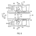
図6は、図4の円弧線5‐5に沿った予混合器170の一実施形態の破断側面図である。図6に示されるように、予混合器170は、矢印200により示されるように逆流路190から燃料を受け取ってもよい。すなわち、燃料は、逆流路190から冷却室194に入り、仕切り202に沿って出口室198に流入してもよい。更に、冷却室194と出口室198との間にバイパス穴214(例えば直交流路)が配置されてもよい。このバイパス穴214は、仕切り202に達するまで壁192に対して半径方向(182)外側へ延出してもよい。すなわち、バイパス穴214は、実際には仕切り202の一部を取り除いて軸方向に仕切り202を貫通するように形成され、それにより、方向矢印215により示されるように燃料は冷却室194から出口室198の中まで直接軸方向に流れてもよい。バイパス穴214は、例えば、冷却室194から出口室198に流れる燃料の総量のうち約1〜50%、5〜40%又は10〜20%を冷却室194と出口室198との間で直接流通させてもよい。バイパス穴214を利用することにより、燃料系統において起こりうる圧力降下の調整、伝導熱伝達係数の調整、又は噴射ポート204への燃料配分の調整が行われてもよい。すなわち、旋回羽根176でバイパス穴214が利用される場合、例えば噴射ポート204へ直接搬送される燃料の量を増減できる。バイパス穴214は噴射ポート204に流入し、噴射ポート204を通過する燃料の配分を改善できる。例えば配分を更に均一にできる。更に、バイパス穴204は、冷却室194から出口室198に至るまでの圧力降下を減少し、それにより噴射ポート204を介して燃料を押し出すのを容易にする。また、バイパス穴214を利用することにより、噴射ポート204を介して予混合器170の中へ噴射される前の燃料流れに含まれる渦巻の量を変更するために燃料噴射ポート204を通過する流れを加減できる。
FIG. 6 is a cutaway side view of one embodiment of
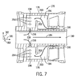
図7は、図4の円弧線5‐5に沿った予混合器170の一実施形態の破断側面図である。予混合器170は、バイパス穴214を除き、図6に示される旋回羽根176の全ての要素を含んでもよい。従って、仕切り202は冷却室194から出口室198へ燃料を直接搬送するためのバイパスを含まない。各旋回羽根176は仕切り202(すなわち冷却室194と出口室198との間ではない場所に)とは別に、方向矢印218により示されるように燃料流路180(すなわち逆流路190からではない)から出口室198の中へ燃料を直接流入させるためのバイパス穴216を含んでもよい。この場合にも、バイパス穴216は、噴射ポート204を通って流れる燃料の総量のうち約1〜50%、5〜40%又は10〜20%の量を出口室198へ流入させることができる。これにより、先の実施形態と同様に、噴射ポート204に流入する燃料の量、配分及び方向を直接制御できると共に、流路180及び190の長さに沿って流れる燃料の量を制御できる。同様に、バイパス穴216は、冷却室194から出口室198に至るまでの燃料の圧力降下を相当に減少することにより、噴射ポート204を通して燃料を押し出すのを容易にする。更なる実施形態において、燃料流路180から出口室198の中へ燃料を直接流入させるバイパス穴216の代わりに又はそれに加えて、バイパス穴216は燃料流路180から冷却室194の中へ燃料を直接流入させてもよい。
FIG. 7 is a cutaway side view of one embodiment of
図8は、図4の円弧線5‐5に沿った予混合器170の一実施形態の破断側面図であり、図6に示される実施形態と図7に示される実施形態との組み合わせを更に示す。図8に示されるように、各旋回羽根176は、逆流路190からのバイパス穴214及び流路180からのバイパス穴216の双方を含んでもよい。この構成において、バイパス穴214及び216は、燃料の総量のうち約5〜60%、10〜50%又は20〜40%の量を先に冷却室194を通して仕切り202に沿って流通させることなく出口室198に直接流入させ、噴射ポート204へ搬送してもよい。これにより、噴射ポート204に直接供給される燃料の量が増加するので、予混合器170の中へ噴射される燃料を更に適切に制御でき且つ燃料の圧力損失を制御できる。しかし、そのような利点がある一方で、方向矢印200に沿った燃料の流れが減少するため、羽根176は完全には冷却されなくなる。
FIG. 8 is a cutaway side view of one embodiment of the
尚、燃料が旋回羽根176を通過する間に、燃料の温度は約50〜500°Fになる。これに対し、合成ガスは約3,000°Fの温度で燃焼できる。従って、予混合器170を製造する際に利用された材料を旋回羽根176において燃料によって冷却することにより、短期間、例えば約15秒、30秒、45秒、60秒、75秒、90秒又はそれを超える時間の間燃焼する合成ガスにさらされた場合でも予混合器170は機能し続ける。予混合器170を製造するために利用される材料は、例えば鋼、又はコバルト及び/又はクロムを含有する合金であってもよい。予混合器170を製造するために使用されてもよい1つの製造技術は、直接金属レーザー焼結処理である。他の製造方法は鋳造及び溶接又はろう付けを含む。予混合器の流路178並びに旋回羽根176の双方に対して冷却媒体として燃料を利用することにより、保炎による炎が流路176に維持される時間は1分までなので燃料ノズル144を損傷するおそれはない。すなわち、通常燃料ノズル144の下流側端部を過ぎて燃焼器146の燃焼室の中まで約0.5〜2インチ入り込んでいる炎は、合成ガス(特に合成ガス中の水素)の高い反応性によって、予混合器170内部の流路178の中まで侵入する逆火の現象を引き起こす。この現象は監視されてもよく、燃料ノズル144の構成要素を冷却することにより、ユーザ又は自動制御システムが燃料の流量を減少するか、空気流量を増加するか、又はノズル144に供給される燃料の組成を変更するかのいずれかを含むが、それに限定されない方法によって予混合器における保炎を排除する時間は1分までである。
It should be noted that while the fuel passes through the
このように、流路及び予混合器170がさらされる温度を全体として低下するための熱交換流体として燃料が作用するので、燃料ノズル144における逆火損傷を減少するのを容易にするために追加の冷却流体を燃料ノズル144に導入する必要はない。更に、旋回羽根176に仕切り202を組み込んだことにより、燃料は旋回羽根176の内部全体にわたり流れるようになるため、予混合器170への逆火が起こった場合に熱交換流体として冷却剤流れを供給できる。従って、高温の熱(例えば約2,000°F)にさらされるために逆火が例えば予混合器170の旋回羽根176を破壊することはなくなり、燃料が旋回羽根176及び逆流路190を通って流れることによって予混合器170の内部で起こる熱伝達により、全体として温度は低下される。その結果、予混合器170がさらされる温度も低下するため、予混合器170及びその内部に配置された旋回羽根176は、予混合器170における逆火又は保炎による損傷に耐えられる。
In this way, the fuel acts as a heat exchange fluid to lower the overall temperature to which the flow path and
以上、最良の態様を含めて本発明を開示するため、並びに任意の装置又はシステムを製造及び使用すること及び取り入れられている任意の方法を実行することを含めて当業者による本発明の実施を可能にするための実施例を使用して、本発明を説明した。特許請求可能な発明の範囲は特許請求の範囲により定義され、当業者が考えつく他の実施例を含んでもよい。そのような他の実施例は、特許請求の範囲において使用される用語と相違しない構造要素を含むのであれば、又は特許請求の範囲において使用される用語と実質的に相違しない同等の構造要素を含むのであれば、特許請求の範囲の範囲内にあることを意図する。 Thus, implementations of the invention by those skilled in the art, including the best mode, and including making and using any apparatus or system and carrying out any methods incorporated are disclosed. The invention has been described using examples to enable it. The patentable scope of the invention is defined by the claims, and may include other examples that occur to those skilled in the art. Such other embodiments include structural elements that do not differ from the terms used in the claims, or equivalent structural elements that do not differ substantially from the terms used in the claims. If included, it is intended to be within the scope of the claims.
100 統合ガス化複合サイクル(IGCC)システム
144 燃料ノズル
146 燃焼器
148 吸気口
166 外側周囲壁
168 ノズル中央本体
170 燃料/空気予混合器
175 上流側端部
176 旋回羽根
177 下流側端部
180 燃料流路
190 逆流路
194 冷却室
198 出口室
202 仕切り
204 燃料噴射ポート
214 バイパス穴
216 バイパス穴
100 Integrated Gasification Combined Cycle (IGCC)
Claims (8)
前記中央本体の周囲に配設された外側管と、
前記中央本体と前記外側管との間に設けられた空気流路と、
前記空気流路に配設された羽根であって、
燃料入口と、
燃料出口と、
前記燃料入口を有する下流側空胴と前記燃料出口を有する上流側空胴との間に配置され、羽根の軸方向を仕切る仕切りと、
を含む羽根と、
前記中央本体を通って前記燃料入口から前記羽根の中まで延出し、前記仕切りに沿って前記燃料入口から前記燃料出口まで非直線方向に前記羽根を通って延出する燃料流路と、
を備える燃料ノズルを備え、
前記上流側空胴は、前記中央本体を通って延出する前記燃料流路からの燃料を前記下流側空胴を通らずに前記上流側空胴の中へ直接搬送するように構成されたバイパス流路を備える、
システム。 The central body,
An outer tube disposed around the central body;
An air flow path provided between the central body and the outer tube;
A vane disposed in the air flow path,
A fuel inlet,
A fuel outlet;
A partition disposed between a downstream cavity having the fuel inlet and an upstream cavity having the fuel outlet, and partitioning the axial direction of the blade;
Including feathers,
A fuel flow path extending through the central body from the fuel inlet into the blade and extending through the blade in a non-linear direction along the partition from the fuel inlet to the fuel outlet;
Comprising a fuel nozzle comprising
The upstream cavity is a bypass configured to directly convey fuel from the fuel flow path extending through the central body into the upstream cavity without passing through the downstream cavity. With a flow path,
system.
Applications Claiming Priority (2)
| Application Number | Priority Date | Filing Date | Title |
|---|---|---|---|
| US12/425,293 | 2009-04-16 | ||
| US12/425,293 US8333075B2 (en) | 2009-04-16 | 2009-04-16 | Gas turbine premixer with internal cooling |
Publications (3)
| Publication Number | Publication Date |
|---|---|
| JP2010249496A JP2010249496A (en) | 2010-11-04 |
| JP2010249496A5 JP2010249496A5 (en) | 2013-02-28 |
| JP5484943B2 true JP5484943B2 (en) | 2014-05-07 |
Family
ID=42335224
Family Applications (1)
| Application Number | Title | Priority Date | Filing Date |
|---|---|---|---|
| JP2010028380A Expired - Fee Related JP5484943B2 (en) | 2009-04-16 | 2010-02-12 | Gas turbine premixer with internal cooling |
Country Status (4)
| Country | Link |
|---|---|
| US (1) | US8333075B2 (en) |
| EP (1) | EP2241815B1 (en) |
| JP (1) | JP5484943B2 (en) |
| CN (1) | CN101865470B (en) |
Families Citing this family (30)
| Publication number | Priority date | Publication date | Assignee | Title |
|---|---|---|---|---|
| US20100170250A1 (en) * | 2009-01-06 | 2010-07-08 | General Electric Company | Fuel Plenum Vortex Breakers |
| US9140454B2 (en) * | 2009-01-23 | 2015-09-22 | General Electric Company | Bundled multi-tube nozzle for a turbomachine |
| US8539773B2 (en) * | 2009-02-04 | 2013-09-24 | General Electric Company | Premixed direct injection nozzle for highly reactive fuels |
| EP2264370B1 (en) * | 2009-06-16 | 2012-10-10 | Siemens Aktiengesellschaft | Burner assembly for a firing assembly for firing fluid fuels and method for operating such a burner assembly |
| US20110265485A1 (en) * | 2010-04-30 | 2011-11-03 | General Electric Company | Fluid cooled injection nozzle assembly for a gas turbomachine |
| US20120144832A1 (en) * | 2010-12-10 | 2012-06-14 | General Electric Company | Passive air-fuel mixing prechamber |
| US20130040254A1 (en) * | 2011-08-08 | 2013-02-14 | General Electric Company | System and method for monitoring a combustor |
| US20130036743A1 (en) * | 2011-08-08 | 2013-02-14 | General Electric Company | Turbomachine combustor assembly |
| US9052112B2 (en) * | 2012-02-27 | 2015-06-09 | General Electric Company | Combustor and method for purging a combustor |
| US9228498B2 (en) | 2012-03-01 | 2016-01-05 | Solar Turbines Incorporated | Laser clad fuel injector premix barrel |
| US9267690B2 (en) | 2012-05-29 | 2016-02-23 | General Electric Company | Turbomachine combustor nozzle including a monolithic nozzle component and method of forming the same |
| US9289826B2 (en) | 2012-09-17 | 2016-03-22 | Honeywell International Inc. | Turbine stator airfoil assemblies and methods for their manufacture |
| US8756934B2 (en) * | 2012-10-30 | 2014-06-24 | General Electric Company | Combustor cap assembly |
| US9874142B2 (en) | 2013-03-07 | 2018-01-23 | General Electric Company | Integrated pyrolysis and entrained flow gasification systems and methods for low rank fuels |
| US9453171B2 (en) | 2013-03-07 | 2016-09-27 | General Electric Company | Integrated steam gasification and entrained flow gasification systems and methods for low rank fuels |
| JP6327826B2 (en) * | 2013-10-11 | 2018-05-23 | 川崎重工業株式会社 | Gas turbine fuel injection device |
| US10731861B2 (en) * | 2013-11-18 | 2020-08-04 | Raytheon Technologies Corporation | Dual fuel nozzle with concentric fuel passages for a gas turbine engine |
| US20150285502A1 (en) * | 2014-04-08 | 2015-10-08 | General Electric Company | Fuel nozzle shroud and method of manufacturing the shroud |
| JP6463947B2 (en) * | 2014-11-05 | 2019-02-06 | 川崎重工業株式会社 | Burner, combustor, and gas turbine |
| US10145561B2 (en) * | 2016-09-06 | 2018-12-04 | General Electric Company | Fuel nozzle assembly with resonator |
| CN106523156B (en) * | 2016-12-30 | 2017-12-01 | 清华大学 | A kind of gas fuel mixer |
| KR102028031B1 (en) * | 2017-10-11 | 2019-10-02 | 두산중공업 주식회사 | Combustor and gas turbine including the same |
| WO2019078921A1 (en) * | 2017-10-20 | 2019-04-25 | Siemens Energy, Inc. | Hybrid manufacturing of a support housing |
| US10502232B2 (en) * | 2018-03-01 | 2019-12-10 | Garrett Transportation I Inc. | Turbocharger compressor having adjustable trim mechanism including swirl inducers |
| CN109237470B (en) * | 2018-08-20 | 2024-02-06 | 华南理工大学 | Cylindrical porous jet type miniature liquid burner and combustion method thereof |
| CN109611889B (en) * | 2018-12-07 | 2020-11-13 | 中国航发沈阳发动机研究所 | Gas fuel nozzle assembly |
| GB201910284D0 (en) * | 2019-07-18 | 2019-09-04 | Rolls Royce Plc | Fuel injector |
| US11512853B2 (en) | 2020-06-30 | 2022-11-29 | General Electric Company | Fuel circuit for a fuel injector |
| US11859535B2 (en) | 2021-03-09 | 2024-01-02 | Rtx Corporation | Fuel-cooled engine component(s) |
| US11920524B2 (en) | 2021-04-15 | 2024-03-05 | Rtx Corporation | Multi-fuel, fuel injection system for a turbine engine |
Family Cites Families (29)
| Publication number | Priority date | Publication date | Assignee | Title |
|---|---|---|---|---|
| GB690632A (en) * | 1950-07-27 | 1953-04-22 | Power Jets Res & Dev Ltd | Improvements in or relating to combustion apparatus |
| EP0393484B1 (en) * | 1989-04-20 | 1992-11-04 | Asea Brown Boveri Ag | Combustion chamber arrangement |
| JP3174638B2 (en) * | 1992-09-18 | 2001-06-11 | 株式会社日立製作所 | Premix structure of gas turbine combustor |
| US5400968A (en) * | 1993-08-16 | 1995-03-28 | Solar Turbines Incorporated | Injector tip cooling using fuel as the coolant |
| US5613363A (en) * | 1994-09-26 | 1997-03-25 | General Electric Company | Air fuel mixer for gas turbine combustor |
| KR100550689B1 (en) * | 1998-02-10 | 2006-02-08 | 제너럴 일렉트릭 캄파니 | Burner with uniform fuel/air premixing for low emissions combustion |
| JP2003074855A (en) * | 2001-08-29 | 2003-03-12 | Mitsubishi Heavy Ind Ltd | Dual combustion nozzle and combustion equipment for gas turbine |
| JP2003148710A (en) * | 2001-11-14 | 2003-05-21 | Mitsubishi Heavy Ind Ltd | Combustor |
| US6675581B1 (en) * | 2002-07-15 | 2004-01-13 | Power Systems Mfg, Llc | Fully premixed secondary fuel nozzle |
| US7165405B2 (en) * | 2002-07-15 | 2007-01-23 | Power Systems Mfg. Llc | Fully premixed secondary fuel nozzle with dual fuel capability |
| US6832481B2 (en) * | 2002-09-26 | 2004-12-21 | Siemens Westinghouse Power Corporation | Turbine engine fuel nozzle |
| US7007477B2 (en) * | 2004-06-03 | 2006-03-07 | General Electric Company | Premixing burner with impingement cooled centerbody and method of cooling centerbody |
| US6993916B2 (en) * | 2004-06-08 | 2006-02-07 | General Electric Company | Burner tube and method for mixing air and gas in a gas turbine engine |
| US7546735B2 (en) * | 2004-10-14 | 2009-06-16 | General Electric Company | Low-cost dual-fuel combustor and related method |
| US20060191268A1 (en) * | 2005-02-25 | 2006-08-31 | General Electric Company | Method and apparatus for cooling gas turbine fuel nozzles |
| JP4486549B2 (en) * | 2005-06-06 | 2010-06-23 | 三菱重工業株式会社 | Gas turbine combustor |
| JP4476176B2 (en) * | 2005-06-06 | 2010-06-09 | 三菱重工業株式会社 | Gas turbine premixed combustion burner |
| US7810333B2 (en) * | 2006-10-02 | 2010-10-12 | General Electric Company | Method and apparatus for operating a turbine engine |
| US20080078183A1 (en) * | 2006-10-03 | 2008-04-03 | General Electric Company | Liquid fuel enhancement for natural gas swirl stabilized nozzle and method |
| US20080267783A1 (en) * | 2007-04-27 | 2008-10-30 | Gilbert Otto Kraemer | Methods and systems to facilitate operating within flame-holding margin |
| US7886545B2 (en) * | 2007-04-27 | 2011-02-15 | General Electric Company | Methods and systems to facilitate reducing NOx emissions in combustion systems |
| US20080276622A1 (en) * | 2007-05-07 | 2008-11-13 | Thomas Edward Johnson | Fuel nozzle and method of fabricating the same |
| US20090056336A1 (en) * | 2007-08-28 | 2009-03-05 | General Electric Company | Gas turbine premixer with radially staged flow passages and method for mixing air and gas in a gas turbine |
| US8661779B2 (en) * | 2008-09-26 | 2014-03-04 | Siemens Energy, Inc. | Flex-fuel injector for gas turbines |
| US8312722B2 (en) * | 2008-10-23 | 2012-11-20 | General Electric Company | Flame holding tolerant fuel and air premixer for a gas turbine combustor |
| US8161750B2 (en) * | 2009-01-16 | 2012-04-24 | General Electric Company | Fuel nozzle for a turbomachine |
| US8607569B2 (en) * | 2009-07-01 | 2013-12-17 | General Electric Company | Methods and systems to thermally protect fuel nozzles in combustion systems |
| US20110265485A1 (en) * | 2010-04-30 | 2011-11-03 | General Electric Company | Fluid cooled injection nozzle assembly for a gas turbomachine |
| US8959921B2 (en) * | 2010-07-13 | 2015-02-24 | General Electric Company | Flame tolerant secondary fuel nozzle |
-
2009
- 2009-04-16 US US12/425,293 patent/US8333075B2/en active Active
-
2010
- 2010-02-10 EP EP10153145.7A patent/EP2241815B1/en active Active
- 2010-02-11 CN CN201010125720.2A patent/CN101865470B/en not_active Expired - Fee Related
- 2010-02-12 JP JP2010028380A patent/JP5484943B2/en not_active Expired - Fee Related
Also Published As
| Publication number | Publication date |
|---|---|
| US8333075B2 (en) | 2012-12-18 |
| EP2241815A3 (en) | 2017-11-01 |
| CN101865470A (en) | 2010-10-20 |
| CN101865470B (en) | 2015-06-03 |
| US20100263383A1 (en) | 2010-10-21 |
| EP2241815B1 (en) | 2019-05-29 |
| EP2241815A2 (en) | 2010-10-20 |
| JP2010249496A (en) | 2010-11-04 |
Similar Documents
| Publication | Publication Date | Title |
|---|---|---|
| JP5484943B2 (en) | Gas turbine premixer with internal cooling | |
| US20100293956A1 (en) | Turbine fuel nozzle having premixer with auxiliary vane | |
| CN101220953B (en) | Fuel-flexible triple-counter-rotating swirler and method of use | |
| JP5331327B2 (en) | Triple ring reversal swirler | |
| RU2560099C2 (en) | Fuel nozzle (versions) | |
| JP5406720B2 (en) | Combustor nozzle for fuel flexible combustion system | |
| JP5921630B2 (en) | How to operate a co-firing system | |
| JP2004101175A (en) | Fluid injection device and fluid injection method | |
| JP4923264B2 (en) | Triple swirl gas turbine combustor | |
| JP2011236889A (en) | Gas turbine cooling configuration | |
| JP2014132214A (en) | Fuel injector for supplying fuel to combustor | |
| JP2010159957A (en) | Method and apparatus for injecting fuel in turbine engine | |
| US9079199B2 (en) | System for increasing the life of fuel injectors | |
| TW201615963A (en) | Axial stage combustion system with exhaust gas recirculation | |
| KR20120083233A (en) | System for flow control in fuel injectors | |
| US20110083444A1 (en) | Low btu fuel injection system | |
| EP2500643B1 (en) | Injector tip | |
| US11346556B2 (en) | Combustor having inner and outer tubular oxygen nozzles about a tubular fuel supply unit | |
| CA2760853A1 (en) | Vortex combustor for low nox emissions when burning lean premixed high hydrogen content fuel | |
| US9453646B2 (en) | Method for air entry in liner to reduce water requirement to control NOx | |
| JP2012255436A (en) | Injector tip assembly and method of fuel injection |
Legal Events
| Date | Code | Title | Description |
|---|---|---|---|
| A521 | Request for written amendment filed |
Free format text: JAPANESE INTERMEDIATE CODE: A523 Effective date: 20130111 |
|
| A621 | Written request for application examination |
Free format text: JAPANESE INTERMEDIATE CODE: A621 Effective date: 20130111 |
|
| A871 | Explanation of circumstances concerning accelerated examination |
Free format text: JAPANESE INTERMEDIATE CODE: A871 Effective date: 20130111 |
|
| A975 | Report on accelerated examination |
Free format text: JAPANESE INTERMEDIATE CODE: A971005 Effective date: 20130206 |
|
| A977 | Report on retrieval |
Free format text: JAPANESE INTERMEDIATE CODE: A971007 Effective date: 20130412 |
|
| A131 | Notification of reasons for refusal |
Free format text: JAPANESE INTERMEDIATE CODE: A131 Effective date: 20130423 |
|
| A521 | Request for written amendment filed |
Free format text: JAPANESE INTERMEDIATE CODE: A523 Effective date: 20130717 |
|
| A131 | Notification of reasons for refusal |
Free format text: JAPANESE INTERMEDIATE CODE: A131 Effective date: 20130910 |
|
| A521 | Request for written amendment filed |
Free format text: JAPANESE INTERMEDIATE CODE: A523 Effective date: 20131204 |
|
| TRDD | Decision of grant or rejection written | ||
| A01 | Written decision to grant a patent or to grant a registration (utility model) |
Free format text: JAPANESE INTERMEDIATE CODE: A01 Effective date: 20140121 |
|
| A61 | First payment of annual fees (during grant procedure) |
Free format text: JAPANESE INTERMEDIATE CODE: A61 Effective date: 20140219 |
|
| R150 | Certificate of patent or registration of utility model |
Ref document number: 5484943 Country of ref document: JP Free format text: JAPANESE INTERMEDIATE CODE: R150 |
|
| R250 | Receipt of annual fees |
Free format text: JAPANESE INTERMEDIATE CODE: R250 |
|
| R250 | Receipt of annual fees |
Free format text: JAPANESE INTERMEDIATE CODE: R250 |
|
| R250 | Receipt of annual fees |
Free format text: JAPANESE INTERMEDIATE CODE: R250 |
|
| R250 | Receipt of annual fees |
Free format text: JAPANESE INTERMEDIATE CODE: R250 |
|
| R250 | Receipt of annual fees |
Free format text: JAPANESE INTERMEDIATE CODE: R250 |
|
| R250 | Receipt of annual fees |
Free format text: JAPANESE INTERMEDIATE CODE: R250 |
|
| LAPS | Cancellation because of no payment of annual fees |