JP5462249B2 - Wound dressing and headgear - Google Patents
Wound dressing and headgear Download PDFInfo
- Publication number
- JP5462249B2 JP5462249B2 JP2011514130A JP2011514130A JP5462249B2 JP 5462249 B2 JP5462249 B2 JP 5462249B2 JP 2011514130 A JP2011514130 A JP 2011514130A JP 2011514130 A JP2011514130 A JP 2011514130A JP 5462249 B2 JP5462249 B2 JP 5462249B2
- Authority
- JP
- Japan
- Prior art keywords
- wound dressing
- thin layer
- dressing according
- compartment
- pillar
- Prior art date
- Legal status (The legal status is an assumption and is not a legal conclusion. Google has not performed a legal analysis and makes no representation as to the accuracy of the status listed.)
- Expired - Fee Related
Links
- 239000000463 material Substances 0.000 claims description 15
- 230000007246 mechanism Effects 0.000 claims description 6
- 229920002457 flexible plastic Polymers 0.000 claims description 5
- 239000011248 coating agent Substances 0.000 claims 1
- 238000000576 coating method Methods 0.000 claims 1
- 206010052428 Wound Diseases 0.000 description 53
- 208000027418 Wounds and injury Diseases 0.000 description 53
- 210000003128 head Anatomy 0.000 description 27
- 206010042674 Swelling Diseases 0.000 description 17
- 230000008961 swelling Effects 0.000 description 17
- 230000002980 postoperative effect Effects 0.000 description 14
- 239000008280 blood Substances 0.000 description 7
- 210000004369 blood Anatomy 0.000 description 7
- 238000000034 method Methods 0.000 description 6
- 230000007423 decrease Effects 0.000 description 4
- 241001465754 Metazoa Species 0.000 description 3
- 239000011324 bead Substances 0.000 description 3
- 230000000740 bleeding effect Effects 0.000 description 2
- 239000012530 fluid Substances 0.000 description 2
- 238000011084 recovery Methods 0.000 description 2
- 239000002210 silicon-based material Substances 0.000 description 2
- 238000001356 surgical procedure Methods 0.000 description 2
- 206010019196 Head injury Diseases 0.000 description 1
- 239000004743 Polypropylene Substances 0.000 description 1
- 239000004793 Polystyrene Substances 0.000 description 1
- 208000002847 Surgical Wound Diseases 0.000 description 1
- 238000009825 accumulation Methods 0.000 description 1
- 239000004676 acrylonitrile butadiene styrene Substances 0.000 description 1
- 239000000853 adhesive Substances 0.000 description 1
- 230000001070 adhesive effect Effects 0.000 description 1
- 230000036770 blood supply Effects 0.000 description 1
- 238000010586 diagram Methods 0.000 description 1
- 230000000694 effects Effects 0.000 description 1
- 239000013013 elastic material Substances 0.000 description 1
- 210000001061 forehead Anatomy 0.000 description 1
- 230000004927 fusion Effects 0.000 description 1
- 230000035876 healing Effects 0.000 description 1
- 230000014759 maintenance of location Effects 0.000 description 1
- 210000000869 occipital lobe Anatomy 0.000 description 1
- 229920000642 polymer Polymers 0.000 description 1
- 229920001155 polypropylene Polymers 0.000 description 1
- 229920002223 polystyrene Polymers 0.000 description 1
- 238000003825 pressing Methods 0.000 description 1
- 230000001681 protective effect Effects 0.000 description 1
- 210000004761 scalp Anatomy 0.000 description 1
- 239000012815 thermoplastic material Substances 0.000 description 1
- 238000007666 vacuum forming Methods 0.000 description 1
- 238000013022 venting Methods 0.000 description 1
- 238000003466 welding Methods 0.000 description 1
Images


Classifications
-
- A—HUMAN NECESSITIES
- A61—MEDICAL OR VETERINARY SCIENCE; HYGIENE
- A61B—DIAGNOSIS; SURGERY; IDENTIFICATION
- A61B17/00—Surgical instruments, devices or methods, e.g. tourniquets
- A61B17/12—Surgical instruments, devices or methods, e.g. tourniquets for ligaturing or otherwise compressing tubular parts of the body, e.g. blood vessels, umbilical cord
- A61B17/132—Tourniquets
-
- A—HUMAN NECESSITIES
- A61—MEDICAL OR VETERINARY SCIENCE; HYGIENE
- A61F—FILTERS IMPLANTABLE INTO BLOOD VESSELS; PROSTHESES; DEVICES PROVIDING PATENCY TO, OR PREVENTING COLLAPSING OF, TUBULAR STRUCTURES OF THE BODY, e.g. STENTS; ORTHOPAEDIC, NURSING OR CONTRACEPTIVE DEVICES; FOMENTATION; TREATMENT OR PROTECTION OF EYES OR EARS; BANDAGES, DRESSINGS OR ABSORBENT PADS; FIRST-AID KITS
- A61F13/00—Bandages or dressings; Absorbent pads
- A61F13/12—Bandages or dressings; Absorbent pads specially adapted for the head or neck
-
- A61F13/01021—
-
- A61F13/01038—
-
- A—HUMAN NECESSITIES
- A61—MEDICAL OR VETERINARY SCIENCE; HYGIENE
- A61F—FILTERS IMPLANTABLE INTO BLOOD VESSELS; PROSTHESES; DEVICES PROVIDING PATENCY TO, OR PREVENTING COLLAPSING OF, TUBULAR STRUCTURES OF THE BODY, e.g. STENTS; ORTHOPAEDIC, NURSING OR CONTRACEPTIVE DEVICES; FOMENTATION; TREATMENT OR PROTECTION OF EYES OR EARS; BANDAGES, DRESSINGS OR ABSORBENT PADS; FIRST-AID KITS
- A61F13/00—Bandages or dressings; Absorbent pads
- A61F13/10—Bandages or dressings; Absorbent pads specially adapted for fingers, hands, or arms; Finger-stalls; Nail-protectors
-
- A—HUMAN NECESSITIES
- A61—MEDICAL OR VETERINARY SCIENCE; HYGIENE
- A61F—FILTERS IMPLANTABLE INTO BLOOD VESSELS; PROSTHESES; DEVICES PROVIDING PATENCY TO, OR PREVENTING COLLAPSING OF, TUBULAR STRUCTURES OF THE BODY, e.g. STENTS; ORTHOPAEDIC, NURSING OR CONTRACEPTIVE DEVICES; FOMENTATION; TREATMENT OR PROTECTION OF EYES OR EARS; BANDAGES, DRESSINGS OR ABSORBENT PADS; FIRST-AID KITS
- A61F13/00—Bandages or dressings; Absorbent pads
- A61F2013/00089—Wound bandages
- A61F2013/00119—Wound bandages elastic
-
- A—HUMAN NECESSITIES
- A61—MEDICAL OR VETERINARY SCIENCE; HYGIENE
- A61F—FILTERS IMPLANTABLE INTO BLOOD VESSELS; PROSTHESES; DEVICES PROVIDING PATENCY TO, OR PREVENTING COLLAPSING OF, TUBULAR STRUCTURES OF THE BODY, e.g. STENTS; ORTHOPAEDIC, NURSING OR CONTRACEPTIVE DEVICES; FOMENTATION; TREATMENT OR PROTECTION OF EYES OR EARS; BANDAGES, DRESSINGS OR ABSORBENT PADS; FIRST-AID KITS
- A61F13/00—Bandages or dressings; Absorbent pads
- A61F2013/00089—Wound bandages
- A61F2013/0017—Wound bandages possibility of applying fluid
- A61F2013/00174—Wound bandages possibility of applying fluid possibility of applying pressure
-
- A—HUMAN NECESSITIES
- A61—MEDICAL OR VETERINARY SCIENCE; HYGIENE
- A61F—FILTERS IMPLANTABLE INTO BLOOD VESSELS; PROSTHESES; DEVICES PROVIDING PATENCY TO, OR PREVENTING COLLAPSING OF, TUBULAR STRUCTURES OF THE BODY, e.g. STENTS; ORTHOPAEDIC, NURSING OR CONTRACEPTIVE DEVICES; FOMENTATION; TREATMENT OR PROTECTION OF EYES OR EARS; BANDAGES, DRESSINGS OR ABSORBENT PADS; FIRST-AID KITS
- A61F13/00—Bandages or dressings; Absorbent pads
- A61F2013/00089—Wound bandages
- A61F2013/0028—Wound bandages applying of mechanical pressure; passive massage
-
- A—HUMAN NECESSITIES
- A61—MEDICAL OR VETERINARY SCIENCE; HYGIENE
- A61F—FILTERS IMPLANTABLE INTO BLOOD VESSELS; PROSTHESES; DEVICES PROVIDING PATENCY TO, OR PREVENTING COLLAPSING OF, TUBULAR STRUCTURES OF THE BODY, e.g. STENTS; ORTHOPAEDIC, NURSING OR CONTRACEPTIVE DEVICES; FOMENTATION; TREATMENT OR PROTECTION OF EYES OR EARS; BANDAGES, DRESSINGS OR ABSORBENT PADS; FIRST-AID KITS
- A61F13/00—Bandages or dressings; Absorbent pads
- A61F2013/00361—Plasters
- A61F2013/00365—Plasters use
- A61F2013/00463—Plasters use haemostatic
- A61F2013/00468—Plasters use haemostatic applying local pressure
-
- A—HUMAN NECESSITIES
- A61—MEDICAL OR VETERINARY SCIENCE; HYGIENE
- A61F—FILTERS IMPLANTABLE INTO BLOOD VESSELS; PROSTHESES; DEVICES PROVIDING PATENCY TO, OR PREVENTING COLLAPSING OF, TUBULAR STRUCTURES OF THE BODY, e.g. STENTS; ORTHOPAEDIC, NURSING OR CONTRACEPTIVE DEVICES; FOMENTATION; TREATMENT OR PROTECTION OF EYES OR EARS; BANDAGES, DRESSINGS OR ABSORBENT PADS; FIRST-AID KITS
- A61F13/00—Bandages or dressings; Absorbent pads
- A61F2013/00361—Plasters
- A61F2013/00544—Plasters form or structure
- A61F2013/00548—Plasters form or structure net
-
- A—HUMAN NECESSITIES
- A61—MEDICAL OR VETERINARY SCIENCE; HYGIENE
- A61F—FILTERS IMPLANTABLE INTO BLOOD VESSELS; PROSTHESES; DEVICES PROVIDING PATENCY TO, OR PREVENTING COLLAPSING OF, TUBULAR STRUCTURES OF THE BODY, e.g. STENTS; ORTHOPAEDIC, NURSING OR CONTRACEPTIVE DEVICES; FOMENTATION; TREATMENT OR PROTECTION OF EYES OR EARS; BANDAGES, DRESSINGS OR ABSORBENT PADS; FIRST-AID KITS
- A61F13/00—Bandages or dressings; Absorbent pads
- A61F2013/00361—Plasters
- A61F2013/00544—Plasters form or structure
- A61F2013/00574—Plasters form or structure shaped as a body part
- A61F2013/00578—Plasters form or structure shaped as a body part conformable; soft or flexible, e.g. elastomeric
-
- A—HUMAN NECESSITIES
- A61—MEDICAL OR VETERINARY SCIENCE; HYGIENE
- A61F—FILTERS IMPLANTABLE INTO BLOOD VESSELS; PROSTHESES; DEVICES PROVIDING PATENCY TO, OR PREVENTING COLLAPSING OF, TUBULAR STRUCTURES OF THE BODY, e.g. STENTS; ORTHOPAEDIC, NURSING OR CONTRACEPTIVE DEVICES; FOMENTATION; TREATMENT OR PROTECTION OF EYES OR EARS; BANDAGES, DRESSINGS OR ABSORBENT PADS; FIRST-AID KITS
- A61F13/00—Bandages or dressings; Absorbent pads
- A61F2013/00361—Plasters
- A61F2013/00544—Plasters form or structure
- A61F2013/00621—Plasters form or structure cast
Description
本発明は、創傷被覆材、特に、ヒトまたは動物患者の身体の一部の術後の腫れを減少させるため、あるいは創傷からの失血を制御するための改良された創傷被覆材に関する。 The present invention relates to a wound dressing, particularly an improved wound dressing for reducing post-operative swelling of a part of a human or animal patient's body or for controlling blood loss from a wound.
本発明はまた、ヒトまたは動物患者の身体部分の術後の腫れを減少させるため、あるいは創傷からの失血を制御するための方法に関する。 The invention also relates to a method for reducing post-operative swelling of a body part of a human or animal patient or for controlling blood loss from a wound.
術後の腫れは、手術の創傷付近の体液の蓄積から生じる。手術後に、治癒を可能にするために創傷が血液供給を必要とし、一部の漏出およびそれによる腫れを必然的に生じるため、術後の腫れは一緒に除去できない。 Postoperative swelling results from the accumulation of fluid near the surgical wound. After surgery, post-operative swelling cannot be removed together because the wound requires a blood supply to allow healing and inevitably results in some leakage and resulting swelling.
腫れは回復を妨げる可能性があり、一部の場合において、さらに合併症を引き起こす可能性があるため、腫れを最小化しようとする問題が常に存在する。 There is always a problem of minimizing swelling because swelling can hinder recovery and in some cases can cause further complications.
特に重大な事故の後の失血の制御は、血液の過剰な損失が回復を妨げ、医学的合併症または死亡までも引き起こす可能性があるため、重要な問題である。 Control of blood loss after a serious accident is an important issue because excessive loss of blood can prevent recovery and even cause medical complications or death.
包帯の使用は術後の腫れを最小化するため、または失血を制御するために当該分野において公知である。包帯の使用は、それらが、異なる身体部分および異なる大きさの創傷での使用に容易に適合できるという点で、それらが一般に多用であるため、魅力的である。 The use of bandages is known in the art to minimize postoperative swelling or to control blood loss. The use of bandages is attractive because they are generally versatile in that they can be easily adapted for use on different body parts and wounds of different sizes.
しかしながら、術後の腫れを最小化するための補助材として使用する場合、包帯はかさばって扱いにくくなり得る。これは特に頭部の外傷に関連する場合であり、使用される包帯のほとんどは創傷と接触せず、むしろ、頭部の周囲にあり、創傷に対して包帯のごく一部を単に保持するだけである。さらに、創傷は、その創傷から体液が過剰に漏出しないことを確実にするために、定期的に検査されることを必要とする。一般に、包帯は、創傷が検査されると捨てられるので、それは無駄になる。 However, when used as an aid to minimize post-operative swelling, the bandage can be bulky and cumbersome. This is especially the case with head trauma, most of the bandages used do not come into contact with the wound, but rather are around the head and simply hold a small part of the bandage against the wound It is. In addition, the wound needs to be inspected regularly to ensure that fluid does not leak excessively from the wound. Generally, the bandage is wasted because it is discarded when the wound is examined.
頭部の外科手術を受けた患者の術後の腫れを最小化することに関連する分野において公知の多くの装置が存在する。 There are a number of devices known in the art relating to minimizing post-operative swelling in patients undergoing head surgery.
特許文献1は、患者の頭部を覆ってフィットするように適合される剛性のキャップ、およびライナーを含む、術後の頭部の被覆材を開示している。ライナーは、単一の開口部に接続された弾力材のチューブの網状構造であり、その開口部を通って、気体がライナーの網状構造を加圧するために導入され得る。ライナーは、頭部を締め付けるためにキャップに対して拡張する。 U.S. Patent No. 6,057,031 discloses a post-operative head covering that includes a rigid cap adapted to fit over a patient's head and a liner. The liner is a network of resilient tubing connected to a single opening through which gas can be introduced to pressurize the liner network. The liner expands against the cap to tighten the head.
特許文献2は、患者の頭部を覆ってフィットするように適合されるキャップを含む、術後の頭部の被覆材を開示している。キャップは、使用の間、空気が排出される気密性のフレキシブルな材料の区画の継ぎはぎであり、それによって、大気圧がフレキシブルな材料を圧迫する。その区画は、ビーズ、好ましくはポリスチレンビーズで充填されるため、空気排出時に、キャップは剛性になるだけでなく、術後の腫れおよび/または頭部創傷からの出血を防ぐために頭皮を穏やかに圧迫する。 U.S. Patent No. 6,099,077 discloses a post-operative head covering that includes a cap adapted to fit over a patient's head. The cap is a seam of an airtight flexible material compartment from which air is exhausted during use, whereby atmospheric pressure compresses the flexible material. The compartment is filled with beads, preferably polystyrene beads, so that when the air is discharged, the cap not only becomes rigid, but also gently compresses the scalp to prevent post-operative swelling and / or bleeding from the head wound To do.
本発明の第1の態様によれば、少なくとも1つの区画を有する密閉された囲いと、少なくとも1つの区画内に配置された複数の離間した柱様構造と、少なくとも1つの区画から空気を排出するための手段と、を備える創傷被覆材であって、少なくとも1つの区画からの空気の排出が、柱様構造の少なくとも2つの間の距離の減少を生じる、創傷被覆材が提供される。 According to a first aspect of the present invention, a sealed enclosure having at least one compartment, a plurality of spaced pillar-like structures disposed in the at least one compartment, and exhausting air from the at least one compartment Means for providing a wound dressing, wherein exhaust of air from at least one compartment results in a decrease in distance between at least two of the pillar-like structures.
柱様構造のうちの少なくとも2つの間の距離の減少は、被覆材の全長を減少させる効果を有し、使用中に創傷に対する被覆材による圧力の付与を生じ、従って、発生する可能性のある腫れの量を抑制する。従って、本発明は創傷の腫れおよび出血を止める改良された創傷被覆材を提供する。 A reduction in the distance between at least two of the pillar-like structures has the effect of reducing the overall length of the dressing, resulting in the application of pressure by the dressing on the wound during use and thus may occur Reduce the amount of swelling. Thus, the present invention provides an improved wound dressing that stops wound swelling and bleeding.
柱様構造は、任意の適切な材料から形成され得る。理想的には、柱様構造は、ゴムベースの材料、シリコンベースの材料またはエラストマーポリマーのいずれかから形成される。 The pillar-like structure can be formed from any suitable material. Ideally, the columnar structure is formed from either a rubber-based material, a silicon-based material or an elastomeric polymer.
好ましくは、柱様構造は所定の配置構成において互いから離間している。 Preferably, the columnar structures are spaced from each other in a predetermined arrangement.
柱様構造を所定の配置構成に配置することによって、空気が区画から排出される場合、圧力が身体部分上に付与され得る方法が制御され得る。例えば、長く薄い平行の片の柱様構造の配置構成は、一軸に沿って、他の軸より大きな減少を生じる。 By arranging the columnar structures in a predetermined arrangement, the manner in which pressure can be applied on the body part when air is exhausted from the compartment can be controlled. For example, an arrangement of long and thin parallel piece columnar structures produces a greater reduction along one axis than the other axis.
簡便には、柱様構造は区画内に均一に間隔をあけている。互いから均一に間隔をあけている柱様構造を有することによって、隣接する柱様構造の間の距離の等しい減少が起こるので、空気が区画から排出されると、身体部分にわたって均一の圧力の付与が生じる。 Conveniently, the columnar structures are evenly spaced within the compartment. By having columnar structures that are uniformly spaced from each other, an equal reduction in the distance between adjacent columnar structures occurs so that when air is expelled from the compartment, a uniform pressure is applied across the body part Occurs.
しかしながら、好ましくは、柱様構造は円筒状の柱であり、柱様構造は任意の適切な断面形状を有する柱から形成されてもよい。例えば、柱様構造は、三角形、長方形、六角形などの断面であってもよい。 However, preferably the columnar structure is a cylindrical column, and the columnar structure may be formed from a column having any suitable cross-sectional shape. For example, the pillar-like structure may be a cross section such as a triangle, a rectangle, or a hexagon.
有利には、各々の柱様構造は、格子様構造を規定するために、接続部材によって隣接する柱様構造に接続される。 Advantageously, each columnar structure is connected to an adjacent columnar structure by a connecting member to define a lattice-like structure.
柱様構造を隣接する構造に接続することにより、通常、ビーズ構造を組み込んでいる上記の従来技術の被覆材に必要とされる使用後の各々の他の構造に対する構造の位置を再調節するための必要性が除去される。 To readjust the position of the structure relative to each other structure after use, typically required for the above prior art dressing incorporating a bead structure, by connecting the columnar structure to an adjacent structure The need for is removed.
接続部材は柱様構造と一体化して形成されてもよい。あるいは、接続部材は柱様構造と結合されてもよい。 The connecting member may be formed integrally with the columnar structure. Alternatively, the connecting member may be combined with the columnar structure.
好ましくは、密閉された囲いは第1の薄層および第2の薄層を含む。 Preferably, the sealed enclosure includes a first lamina and a second lamina.
第1の薄層および第2の薄層は任意の適切な材料から形成されてもよい。理想的には、第1の薄層および第2の薄層はPVCなどの真空成形材料から形成される。 The first thin layer and the second thin layer may be formed from any suitable material. Ideally, the first thin layer and the second thin layer are formed from a vacuum forming material such as PVC.
好ましくは、第1の薄層および第2の薄層は、密閉された囲いを規定するためにそれらの端部の周囲で一緒に結合される。従って、柱様構造は第1の薄層と第2の薄層との間に保持される。 Preferably, the first lamina and the second lamina are bonded together around their ends to define a sealed enclosure. Thus, the columnar structure is held between the first thin layer and the second thin layer.
第1の薄層および第2の薄層は、任意の適切な手段によって一緒に結合されてもよい。例えば薄層は、熱融着、超音波による溶接または一緒に接着されてもよい。 The first thin layer and the second thin layer may be joined together by any suitable means. For example, the thin layers may be heat sealed, ultrasonic welded or bonded together.
好ましくは、複数の柱様構造は第1の薄層と第2の薄層との間に移動可能に保持される。 Preferably, the plurality of columnar structures are held movably between the first thin layer and the second thin layer.
好ましくは、複数の柱様構造は、第1の薄層および/または第2の薄層への接続によって第1の薄層と第2の薄層との間の位置に保持される。 Preferably, the plurality of columnar structures are held in a position between the first thin layer and the second thin layer by connection to the first thin layer and / or the second thin layer.
柱様構造は、例えば熱融着、超音波による溶接または接着材などの任意の適切な手段によって第1の薄層と第2の薄層との間の位置に保持されてもよい。 The columnar structure may be held in position between the first and second lamina by any suitable means such as, for example, thermal fusion, ultrasonic welding or adhesive.
好ましくは、複数の柱様構造は、少なくとも1つの薄層と一体化して形成される。 Preferably, the plurality of columnar structures are formed integrally with at least one thin layer.
好ましくは、空気が区画から排出される場合、第1の薄層の一部は、少なくとも2つの柱様構造の間のスペース内に引き寄せられるように適合される。第1の薄層がスペース内に引き寄せられる場合、創傷被覆材の寸法は減少し、少なくとも2つの柱様構造の間の距離の減少が生じる。 Preferably, when air is exhausted from the compartment, a portion of the first lamina is adapted to be drawn into the space between the at least two pillar-like structures. When the first lamina is pulled into the space, the size of the wound dressing decreases, resulting in a decrease in the distance between at least two pillar-like structures.
好ましくは、創傷被覆材は、被覆材を患者の頭部に取り付けるためのフレーム部分をさらに含む。 Preferably, the wound dressing further comprises a frame portion for attaching the dressing to the patient's head.
簡便には、フレーム部分は、患者の頭部に被覆材を固定するための固定バンドを含む。 Conveniently, the frame portion includes a securing band for securing the dressing to the patient's head.
好ましくは、フレーム部分は固定バンドの作用長さを調節するための手段を含む。 Preferably, the frame portion includes means for adjusting the working length of the fixation band.
固定バンドの作用長さを調節するための手段により、創傷被覆材を異なるサイズの頭部に使用することが可能になる。 The means for adjusting the working length of the fixation band allows the wound dressing to be used on different sized heads.
好ましくは、固定バンドの作用長さを調節するための手段は、歯止めおよびラチェット機構を含む。 Preferably, the means for adjusting the working length of the fixation band includes pawl and ratchet mechanisms.
歯止めおよびラチェット機構は、当該分野において公知の種類の自己制限歯止めおよびラチェット機構であり得る。 The pawl and ratchet mechanism may be a self-limiting pawl and ratchet mechanism of the type known in the art.
好ましくは、固定バンドのサイズを調節するための手段は、クリップ調節器を含む。 Preferably, the means for adjusting the size of the fixation band includes a clip adjuster.
好ましくは、フレーム部分は、使用の際に、固定バンドと独立して創傷被覆材が外れることを抑制するように適合される保持部材をさらに含む。 Preferably, the frame portion further includes a retaining member adapted to prevent the wound dressing from coming off independent of the fixation band in use.
好ましくは、フレーム部分は、可撓性のプラスチック材料を含む。 Preferably, the frame portion comprises a flexible plastic material.
可撓性のプラスチック材料は、好ましくは熱可塑性材料、理想的にはアクリロニトリルブタジエンスチレン(ABS)またはポリプロペン(PB)である。 The flexible plastic material is preferably a thermoplastic material, ideally acrylonitrile butadiene styrene (ABS) or polypropene (PB).
好ましくは、少なくとも1つの区画から空気を排出するための手段は、真空放出弁を含む。 Preferably, the means for exhausting air from the at least one compartment includes a vacuum release valve.
少なくとも1つの区画から空気を排出するための手段は、区画から空気を排出している間の少なくとも1つの区画への空気の後戻りを防ぐために、逆止弁をさらに含んでもよい。 The means for exhausting air from the at least one compartment may further include a check valve to prevent return of air to the at least one compartment while exhausting air from the compartment.
好ましくは、創傷被覆材は、空気を少なくとも1つの区画に導入するための手段をさらに含む。空気を少なくとも1つの区画内に導入するための手段は、コンプレッサーに接続可能なハンドポンプまたは吸入弁の形態であってもよい。 Preferably, the wound dressing further comprises means for introducing air into at least one compartment. The means for introducing air into the at least one compartment may be in the form of a hand pump or suction valve connectable to the compressor.
本発明の第2の態様によれば、ヒトまたは動物患者の身体部分の術後の腫れを減少させるか、あるいは創傷から失血を制御するための方法が提供され、その方法は、以下の工程、
a)身体部分または創傷に、少なくとも1つの区画および複数の離間した柱様構造を有する密閉された囲いによって形成される被覆材を適用する工程と、
b)少なくとも1つの区画の空気を排出することによって、少なくとも一対の柱様構造の間の間隔を減少させることによって、身体部分または創傷に圧力を付与する工程と、を含む。
According to a second aspect of the present invention there is provided a method for reducing post-operative swelling of a body part of a human or animal patient or for controlling blood loss from a wound comprising the following steps:
a) applying to the body part or wound a dressing formed by a sealed enclosure having at least one compartment and a plurality of spaced pillar-like structures;
b) applying pressure to the body part or wound by evacuating at least one compartment air, thereby reducing the spacing between at least one pair of pillar-like structures.
本発明の第3の態様によれば、ヘッドカバー部分と、固定バンドを含むフレーム部分とを含む、ヘッドギアであって、フレーム部分は、ヘッドギアの片側に配置される少なくとも1つの保持部材をさらに含み、保持部材は、使用の際に、固定バンドと独立してヘッドギアが外れることを抑制する、ヘッドギアが提供される。 According to a third aspect of the present invention, the headgear includes a head cover portion and a frame portion including a fixed band, the frame portion further including at least one holding member disposed on one side of the headgear, The holding member is provided with a headgear that prevents the headgear from coming off independently of the fixed band in use.
従って、本発明の第3の態様は、ヘッドギアの固定が固定バンドおよび少なくとも1つの保持部材によって与えられる場合、顎ひもを必要とせずに、ヘッドギアを使用者の頭部に固定することを可能にする。 Thus, the third aspect of the present invention allows the headgear to be secured to the user's head without the need for a chin strap when the headgear is secured by a securing band and at least one retaining member. To do.
ここで、添付の図面を参照して、非限定的な例として本発明の好ましい実施形態の詳細を示す。 Details of preferred embodiments of the invention will now be given by way of non-limiting example with reference to the accompanying drawings.
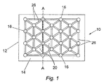
図1および図2を参照すると、本発明による創傷被覆材(10)の第1の実施形態が示される。創傷被覆材(10)は、少なくとも1つの区画(14)を有する密閉された囲い(12)と、少なくとも1つの区画(14)内に配置される複数の離間した柱様構造(16)と、少なくとも1つの区画から空気を排出するための手段(示さず)と、を備える。 With reference to FIGS. 1 and 2, a first embodiment of a wound dressing (10) according to the present invention is shown. The wound dressing (10) includes a sealed enclosure (12) having at least one compartment (14) and a plurality of spaced pillar-like structures (16) disposed within the at least one compartment (14); Means (not shown) for exhausting air from at least one compartment.
密閉された囲い(12)は第1の薄層(22)および第2の薄層(24)を備え、その第1の薄層(22)および第2の薄層(24)は、密閉された囲い(12)を規定するために、それらの端部の周囲で一緒に密閉される。第1の薄層(22)および第2の薄層(24)はさらに、密閉された囲い(12)内の1つ以上のさらなる区画を規定するために、様々な点で一緒に結合されてもよい。 The sealed enclosure (12) comprises a first thin layer (22) and a second thin layer (24), the first thin layer (22) and the second thin layer (24) being sealed. To define the enclosure (12), they are sealed together around their ends. The first lamina (22) and the second lamina (24) are further joined together at various points to define one or more additional compartments within the sealed enclosure (12). Also good.
第1の薄層(22)および第2の薄層(24)はPVC材料から製造され、密閉された囲い(12)および/または区画を規定するために、互いに熱融着される。 The first lamina (22) and the second lamina (24) are made from PVC material and are heat sealed to each other to define a sealed enclosure (12) and / or compartment.
柱様構造(16)(本明細書中で以下「柱」という)は、実質的に円筒状の形状であり、接続部材(26)によって隣接する構造に接続される。この構成において、柱(16)および接続部材(26)は格子様構造を規定する。好ましい実施形態において、柱はシリコンベースの材料から製造され、接続部材(26)は可撓性のプラスチック材料などの弾性材料から製造される。 The columnar structure (16) (hereinafter referred to as “column”) has a substantially cylindrical shape and is connected to an adjacent structure by a connecting member (26). In this configuration, the columns (16) and connecting members (26) define a lattice-like structure. In a preferred embodiment, the post is made from a silicon-based material and the connecting member (26) is made from an elastic material, such as a flexible plastic material.
柱(16)は、第1の薄層(22)と第2の薄層(24)との間に移動可能に保持されてもよいか、あるいは第1の薄層および/または第2の薄層に接続することによって薄層(22,24)の間の位置に保持されてもよい。 The pillar (16) may be movably held between the first thin layer (22) and the second thin layer (24), or the first thin layer and / or the second thin layer. It may be held in position between the thin layers (22, 24) by connecting to the layers.
少なくとも1つの区画から空気を排出するための手段は、区画(14)から空気を排出している間に少なくとも1つの区画への空気の後戻りを防ぐために、逆止弁を有する真空放出弁(図示せず)の形態である。 The means for exhausting air from the at least one compartment is a vacuum release valve (see FIG. 5) having a check valve to prevent the return of air to the at least one compartment while exhausting air from the compartment (14). (Not shown).
図3aおよび3bを参照すると、空気が区画(14)から排出される場合、第1の薄層(22)の一部および第2の薄層(24)の一部が、2つの隣接する柱(16)の間のスペース(20)内に引き寄せられる(図3bに最適な状態を示す)。薄層(22、24)は、そこから空気を排出することによる真空状態によってスペース(20)内に引き寄せられるため、創傷被覆材(10)の全表面積は減少し、隣接する柱(16)の間の空間の減少を生じる。 Referring to FIGS. 3a and 3b, when air is exhausted from the compartment (14), a portion of the first lamina (22) and a portion of the second lamina (24) are two adjacent pillars. Is drawn into the space (20) between (16) (shown in an optimal state in FIG. 3b). Since the thin layers (22, 24) are drawn into the space (20) by the vacuum condition by exhausting air therefrom, the total surface area of the wound dressing (10) is reduced and the adjacent pillars (16) Resulting in a reduction in the space between.
隣接する柱(16)は互いに対して引き寄せられるため、接続部材(26)はスペース(20)の内側に曲がるようになる。 Adjacent columns (16) are drawn toward each other, so that the connecting member (26) bends inside the space (20).
薄層(22、24)は、空気が排出される場合、1つまたは2つの軸において創傷被覆材(10)の、制御され、かつ自己制限された長さの減少を与える。 The thin layers (22, 24) provide a controlled and self-limited length reduction of the wound dressing (10) in one or two axes when air is exhausted.
空気が区画(14)に再導入される場合、柱(16)は、接続部材(26)が真っ直ぐになり、従って柱(16)を互いから離して押す、接続部材(26)の弾力性に起因してそれらの元の間隔に戻る。 When air is re-introduced into the compartment (14), the pillar (16) causes the connecting member (26) to be straight, thus pushing the pillars (16) away from each other, thereby making the connecting member (26) elastic. Due to returning to their original interval.
柱(16)は、必要に応じて所定の構成において互いから離間している。すなわち、格子要素(つまり柱(16)および接続部材(26))の形状および間隔により、真空が適用される場合、被覆材(10)がどのように変化するかが決定する。例えば、柱(16)が互いに平行しているひと続きの長い薄片で構成される場合、縦軸より横軸に沿って大きく減少する。 The columns (16) are spaced from each other in a predetermined configuration as required. That is, the shape and spacing of the grid elements (i.e. pillars (16) and connecting members (26)) determine how the dressing (10) changes when a vacuum is applied. For example, if the column (16) is composed of a series of long slices parallel to each other, it will decrease significantly along the horizontal axis rather than the vertical axis.
創傷被覆材(10)はさらに、コンプレッサーに接続可能なハンドポンプまたは吸入弁の形態であり得る、少なくとも1つの区画に空気を導入するための手段(図示せず)を備える。 The wound dressing (10) further comprises means (not shown) for introducing air into at least one compartment, which may be in the form of a hand pump or suction valve connectable to a compressor.
図4を参照すると、患者の腕の術後の腫れを減少させるために、患者の腕に適用されている本発明の第1の実施形態による創傷被覆材が示される。 Referring to FIG. 4, a wound dressing according to a first embodiment of the present invention applied to a patient's arm to reduce post-operative swelling of the patient's arm is shown.
創傷被覆材はまず、術後の創傷に周りに配置され、バンド、ストラップ、VELCRO(登録商標)、テープなどの適切な手段によって所定の位置に固定される。次いで、圧力が、少なくとも1つの区画の空気を排出することによって身体部分の腫れを抑制するために身体部分に付与される。上記のように、空気の排出により、薄層(22、24)が、柱(16)の間のスペース(20)内に引き寄せられ、その結果として柱(16)が互いに引き寄せられ、創傷被覆材(10)の全体寸法が減少する。 The wound dressing is first placed around the post-operative wound and secured in place by suitable means such as a band, strap, VELCRO®, tape or the like. Pressure is then applied to the body part to suppress swelling of the body part by exhausting air from at least one compartment. As described above, the discharge of air causes the lamina (22, 24) to be drawn into the space (20) between the pillars (16), with the result that the pillars (16) are drawn together, and the wound dressing. The overall dimension of (10) is reduced.
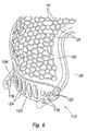
図5を参照すると、本発明による創傷被覆材の第2の実施形態が示される。創傷被覆材(100)は頭部の創傷被覆材の形状であり、ヘッドカバー部分(102)および患者の頭部に被覆材を取り付けるためのフレーム部分(104)を備える。 Referring to FIG. 5, a second embodiment of a wound dressing according to the present invention is shown. The wound dressing (100) is in the form of a head wound dressing and comprises a head cover portion (102) and a frame portion (104) for attaching the dressing to the patient's head.
ヘッドカバー部分(102)は上記の創傷被覆材(10)と同様の構造であり、同じ参照番号が同一の特徴を特定するために使用されている。 The head cover portion (102) is similar in structure to the wound dressing (10) described above, and the same reference numerals are used to identify the same features.
フレーム部分(104)は、患者の頭部に被覆材(100)を固定するための固定バンド(106)と、被覆材(100)の対向する側に配置され、装着されるときに患者の頭部のいずれかの側に配置されるように位置する一対の保持部材(114)とを備える。 The frame portion (104) is disposed on the opposite side of the covering material (100) and the fixing band (106) for fixing the covering material (100) to the patient's head, and when attached to the patient's head A pair of holding members (114) positioned so as to be arranged on either side of the unit.
フレーム部分(104)の構成要素は、それらが、頭部の周りに快適に適合するが、伸縮しないように十分剛性であり、創傷被覆材(100)を頭部から外しにくくなり得るように可撓性のプラスチックから製造される。 The components of the frame portion (104) may be such that they fit comfortably around the head but are sufficiently rigid so that they do not stretch and may be difficult to remove the wound dressing (100) from the head. Manufactured from flexible plastic.
固定バンド(106)は、患者の頭部の周囲にわたるように適合される。示される実施形態において、固定バンド(106)は、使用者の額からこめかみに沿って下方に延びて、固定した持続を与えるために後頭葉の下で終わるように各々適合される2つのバンド部材(108)を備える。 The fixation band (106) is adapted to span around the patient's head. In the embodiment shown, the fixation band (106) extends from the user's forehead down along the temple and is each adapted to end under the occipital lobe to provide a fixed duration. (108).
フレーム部分(104)はさらに、固定バンド(106)の有効長を調節するための手段を備える。示される実施形態において、被覆材(100)は、その創傷被覆材(100)の前部に位置する固定バンド(106)の有効長を調節するための第1の手段、およびその創傷被覆材(100)の後部に位置する固定バンド(106)の有効長を調節するための第2の手段を備える。 The frame portion (104) further comprises means for adjusting the effective length of the fixed band (106). In the embodiment shown, the dressing (100) comprises a first means for adjusting the effective length of the fixation band (106) located in front of the wound dressing (100), and the wound dressing ( 100) second means for adjusting the effective length of the fixed band (106) located at the rear.
前部の調節手段は、2つのバンド部材(108)の第1の端部に接続される歯止めおよびラチェット機構(110)である。歯止めおよびラチェット機構は、固定バンド(106)の前部の伸長を調節するためのノブ(126)を備える。 The front adjustment means is a pawl and ratchet mechanism (110) connected to the first ends of the two band members (108). The pawl and ratchet mechanism includes a knob (126) for adjusting the extension of the front of the fixation band (106).
図6を参照すると、後部の調節手段は、当該分野において公知のものと同様の種類のクリップ調節器(112)である。クリップ調節器(112)は、各々のバンド部材(108)の第2の端部に近接して配置される複数の小穴(118)を備える。小穴(118)は、取り付け部材(122)に配置される対応する突起(120)を受容するように適合される。小穴(118)および対応する突起(120)の数は、固定バンド(106)の後部の伸長を増加させるために利用することができる調節位置の数を決定する。示される実施形態において、各々のバンド部材(108)は4つの小穴(118)を備える。図6に示されるように、取り付け部材(122)は、バンド部材(118)の端部を固定してしまい込むことができる複数の受容ループ(124)を組み込んでもよい。 Referring to FIG. 6, the rear adjustment means is a clip adjuster (112) of the same type as known in the art. The clip adjuster (112) includes a plurality of eyelets (118) disposed proximate to the second end of each band member (108). The eyelet (118) is adapted to receive a corresponding protrusion (120) disposed on the attachment member (122). The number of eyelets (118) and corresponding protrusions (120) determine the number of adjustment positions that can be utilized to increase the rear extension of the fixation band (106). In the embodiment shown, each band member (108) comprises four eyelets (118). As shown in FIG. 6, the attachment member (122) may incorporate a plurality of receiving loops (124) that can lock in the ends of the band member (118).
各々の保持部材(114)は、使用者の耳の周囲にフィットするように適合される。示される実施形態において、保持部材(114)の第1の端部は、創傷被覆剤(100)の前端部に近接する位置で固定バンド(106)に接続され、第2の端部は、創傷被覆材(100)の後端部に近接する固定バンド(106)に接続される。 Each retaining member (114) is adapted to fit around the user's ear. In the embodiment shown, the first end of the retention member (114) is connected to the fixation band (106) at a location proximate to the front end of the wound dressing (100) and the second end is the wound. It is connected to a fixed band (106) close to the rear end of the covering (100).
保持部材(114)は、固定バンド(106)と独立してヘッドギアが外れるのを抑制するように作動し、かつ、顎ひもを使用せずに、または耳を隠さずに固定バンド(106)とともに創傷被覆材(100)を頭部に固定させる。 The retaining member (114) operates to restrain the headgear from coming off independently of the fixation band (106) and works with the fixation band (106) without using a chin strap or hiding the ear. The wound dressing (100) is fixed to the head.
創傷被覆材(100)のフレーム構造は、頭部の創傷の術後の腫れを減少させるのに使用するため、または頭部の創傷から失血を制御するためのヘッドギアにおいて使用するために特定の参照とともに記載されているが、上記の特有のフレーム構造が、使用者の頭部にヘッドギアを固定することが必要とされる場合、ヘッドギアに組み込まれてもよい。例えば、フレーム構造は、顎ひもを使用せずにヘルメットを提供するために安全用または保護用ヘルメットに組み込まれてもよい。 The frame structure of the wound dressing (100) is a specific reference for use in reducing post-operative swelling of the head wound or in headgear for controlling blood loss from the head wound. Although described above, the specific frame structure described above may be incorporated into the headgear if it is required to fix the headgear to the user's head. For example, the frame structure may be incorporated into a safety or protective helmet to provide a helmet without the use of chin straps.
本明細書に開示される全ての特徴(添付の特許請求の範囲、要約および図面のいずれかを含む)、および/または開示される任意の方法もしくはプロセスの全ての工程は、そのような特徴および/または工程の少なくとも一部が相互排他的である組み合わせを除いて任意の組み合わせで組み合わされてもよい。 All features disclosed herein (including any of the appended claims, abstracts and drawings), and / or every step of any method or process disclosed are such features and It may be combined in any combination except for a combination in which at least some of the steps are mutually exclusive.
本明細書に開示される各々の特徴(添付の特許請求の範囲、要約および図面のいずれかを含む)は、他に明確に記載されない限り、同様のもの、等価物または同様の目的を与える、代替の特徴と置き換えられてもよい。従って、他に明確に記載されない限り、開示される各々の特徴は、等価物または類似の特徴の一般的な組の一例のみである。 Each feature disclosed in this specification (including any of the appended claims, abstract and drawings) provides the same, equivalent or similar purpose unless explicitly stated otherwise. Alternative features may be substituted. Thus, unless expressly stated otherwise, each feature disclosed is one example only of a generic set of equivalent or similar features.
本発明は任意の上述の実施形態の詳細に限定されない。本発明は、本明細書に開示される特徴(添付の特許請求の範囲、要約および図面のいずれかを含む)の任意の新規のものまたは任意の新規の組み合わせ、あるいは開示される任意の方法またはプロセスの工程の任意の新規のものまたは任意の新規の組み合わせにまで及ぶ。 The invention is not limited to the details of any of the above-described embodiments. The invention may be any novel or any novel combination of features disclosed herein (including any of the appended claims, abstracts and drawings), or any method or It extends to any new or any new combination of process steps.
Claims (17)
前記密閉された囲いは、第1の薄層および第2の薄層を含み、
前記少なくとも1つの区画からの空気の排出により、前記第1の薄層の一部が少なくとも2つの前記柱様構造のスペース内に引き寄せられ、その結果、少なくとも2つの前記柱様構造が互いに引き寄せられ、全長が減少する、創傷被覆材。 A wound dressing comprising a sealed enclosure having at least one compartment, a plurality of spaced pillar-like structures disposed within the at least one compartment, and means for exhausting air from the at least one compartment Material,
The sealed enclosure includes a first lamina and a second lamina;
By the discharge of air from the at least one compartment, said first portion of the thin layer are attracted to the space within the at least two of the pillars like structure, such that at least two of said post-like structures are drawn together Wound dressing , the overall length is reduced .
前記ヘッドカバー部分は請求項1〜9のいずれか一項に記載の創傷被覆材であり、
前記フレーム部分は、前記ヘッドギアの片側に配置される少なくとも1つの保持部材をさらに含み、前記保持部材は、使用の際に、前記固定バンドと独立して前記ヘッドギアが外れることを抑制する、ヘッドギア。 A headgear including a head cover portion and a frame portion including a fixed band,
The head cover part is the wound dressing according to any one of claims 1 to 9,
The frame portion further includes at least one holding member disposed on one side of the headgear, and the holding member prevents the headgear from being detached independently of the fixed band during use.
Applications Claiming Priority (3)
| Application Number | Priority Date | Filing Date | Title |
|---|---|---|---|
| GB0811136.1 | 2008-06-18 | ||
| GB0811136A GB2461048C (en) | 2008-06-18 | 2008-06-18 | Improved wound dressing |
| PCT/GB2009/050688 WO2009153594A1 (en) | 2008-06-18 | 2009-06-17 | Wounddressing and headgear |
Publications (3)
| Publication Number | Publication Date |
|---|---|
| JP2011524768A JP2011524768A (en) | 2011-09-08 |
| JP2011524768A5 JP2011524768A5 (en) | 2012-03-22 |
| JP5462249B2 true JP5462249B2 (en) | 2014-04-02 |
Family
ID=39672461
Family Applications (1)
| Application Number | Title | Priority Date | Filing Date |
|---|---|---|---|
| JP2011514130A Expired - Fee Related JP5462249B2 (en) | 2008-06-18 | 2009-06-17 | Wound dressing and headgear |
Country Status (16)
| Country | Link |
|---|---|
| US (1) | US8481804B2 (en) |
| EP (1) | EP2293749B1 (en) |
| JP (1) | JP5462249B2 (en) |
| KR (1) | KR101459745B1 (en) |
| CN (1) | CN102083398B (en) |
| AU (1) | AU2009261685B2 (en) |
| BR (1) | BRPI0914844A2 (en) |
| CA (1) | CA2728157C (en) |
| ES (1) | ES2602115T3 (en) |
| GB (1) | GB2461048C (en) |
| IL (1) | IL210050A (en) |
| MX (1) | MX2010013982A (en) |
| MY (1) | MY159462A (en) |
| RU (1) | RU2504355C2 (en) |
| WO (1) | WO2009153594A1 (en) |
| ZA (1) | ZA201100372B (en) |
Families Citing this family (55)
| Publication number | Priority date | Publication date | Assignee | Title |
|---|---|---|---|---|
| WO2009066106A1 (en) | 2007-11-21 | 2009-05-28 | Smith & Nephew Plc | Wound dressing |
| AU2008327660B2 (en) | 2007-11-21 | 2014-02-13 | Smith & Nephew Plc | Wound dressing |
| GB0804654D0 (en) | 2008-03-13 | 2008-04-16 | Smith & Nephew | Vacuum closure device |
| MX358022B (en) | 2011-02-04 | 2018-08-02 | Univ Massachusetts | Negative pressure wound closure device. |
| US9421132B2 (en) | 2011-02-04 | 2016-08-23 | University Of Massachusetts | Negative pressure wound closure device |
| CN103857365B (en) | 2011-07-14 | 2017-06-23 | 史密夫及内修公开有限公司 | Wound dressing and treatment method |
| US10220125B2 (en) | 2012-02-03 | 2019-03-05 | Smith & Nephew Plc | Apparatuses and methods for wound therapy |
| JP6250571B2 (en) | 2012-03-12 | 2017-12-20 | スミス アンド ネフュー ピーエルシーSmith & Nephew Public Limited Company | Pressure reducing apparatus and method |
| WO2014013348A2 (en) | 2012-05-22 | 2014-01-23 | Smith & Nephew Plc | Wound closure device |
| JP6382185B2 (en) | 2012-05-22 | 2018-08-29 | スミス アンド ネフュー ピーエルシーSmith & Nephew Public Limited Company | Apparatus and method for wound treatment |
| MX2014014325A (en) | 2012-05-24 | 2015-08-06 | Smith & Nephew Inc | Devices and methods for treating and closing wounds with negative pressure. |
| CA2879357C (en) | 2012-07-16 | 2022-08-23 | Smith & Nephew, Inc. | Negative pressure wound closure device |
| CN104540484B (en) * | 2012-08-07 | 2018-05-25 | 株式会社瑞光 | Disposable wearing product |
| AU2014248519B2 (en) | 2013-03-13 | 2018-12-20 | Smith & Nephew Inc. | Negative pressure wound closure device and systems and methods of use in treating wounds with negative pressure |
| CN105007870B (en) | 2013-03-14 | 2019-12-13 | 史密夫及内修公开有限公司 | Compressible wound fillers, systems and methods for use in treating wounds with negative pressure |
| CN106170275B (en) | 2013-10-21 | 2021-05-07 | 史密夫和内修有限公司 | Negative pressure wound closure device |
| EP3096725B1 (en) | 2014-01-21 | 2023-10-18 | Smith & Nephew plc | Wound treatment apparatuses |
| CN110974539A (en) | 2014-01-21 | 2020-04-10 | 史密夫及内修公开有限公司 | Collapsible dressing for negative pressure wound therapy |
| US9867965B1 (en) | 2014-04-25 | 2018-01-16 | Byo Health, L.L.C. | Medical bandage for the head, a limb or a stump |
| GB2525658B (en) * | 2014-05-01 | 2016-05-18 | Timothy Jake | Improved wound dressing |
| GB2529699A (en) * | 2014-08-29 | 2016-03-02 | Airhead Design Ltd | Inflatable helmet |
| GB2536264B (en) * | 2015-03-11 | 2017-11-08 | Timothy Jake | Graduated pressure applicator |
| JP6743050B2 (en) | 2015-04-27 | 2020-08-19 | スミス アンド ネフュー ピーエルシーSmith & Nephew Public Limited Company | Pressure reducing device and method |
| AU2016254119A1 (en) | 2015-04-29 | 2017-10-05 | Smith & Nephew Inc. | Negative pressure wound closure device |
| US10575991B2 (en) | 2015-12-15 | 2020-03-03 | University Of Massachusetts | Negative pressure wound closure devices and methods |
| US10814049B2 (en) | 2015-12-15 | 2020-10-27 | University Of Massachusetts | Negative pressure wound closure devices and methods |
| CA3016484A1 (en) | 2016-03-07 | 2017-09-14 | Smith & Nephew Plc | Wound treatment apparatuses and methods with negative pressure source integrated into wound dressing |
| WO2017186771A1 (en) | 2016-04-26 | 2017-11-02 | Smith & Nephew Plc | Wound dressings and methods of use with integrated negative pressure source having a fluid ingress inhibition component |
| CN109069710B (en) | 2016-05-03 | 2022-04-12 | 史密夫及内修公开有限公司 | Optimizing power delivery to a negative pressure source in a negative pressure therapy system |
| US11096831B2 (en) | 2016-05-03 | 2021-08-24 | Smith & Nephew Plc | Negative pressure wound therapy device activation and control |
| CN109069711A (en) | 2016-05-03 | 2018-12-21 | 史密夫及内修公开有限公司 | System and method for driving negative pressure source in negative pressure treatment system |
| AU2017315129B2 (en) | 2016-08-25 | 2022-10-27 | Smith & Nephew Plc | Absorbent negative pressure wound therapy dressing |
| WO2018041805A1 (en) | 2016-08-30 | 2018-03-08 | Smith & Nephew Plc | Systems for applying reduced pressure therapy |
| US11096832B2 (en) | 2016-09-27 | 2021-08-24 | Smith & Nephew Plc | Wound closure devices with dissolvable portions |
| AU2017336310B2 (en) | 2016-09-30 | 2022-12-08 | Smith & Nephew Plc | Negative pressure wound treatment apparatuses and methods with integrated electronics |
| GB2555584B (en) * | 2016-10-28 | 2020-05-27 | Smith & Nephew | Multi-layered wound dressing and method of manufacture |
| CA3042673A1 (en) | 2016-11-02 | 2018-05-11 | Smith & Nephew Inc. | Wound closure devices |
| CN110582257B (en) | 2017-03-08 | 2022-03-15 | 史密夫及内修公开有限公司 | Negative pressure wound therapy device control in the presence of fault conditions |
| CN110612131B (en) | 2017-05-09 | 2023-05-16 | 史密夫及内修公开有限公司 | Redundant control for negative pressure wound therapy system |
| WO2018229010A1 (en) | 2017-06-13 | 2018-12-20 | Smith & Nephew Plc | Collapsible structure and method of use |
| US11872110B2 (en) | 2017-06-13 | 2024-01-16 | Smith & Nephew Plc | Wound closure device and method of use |
| CN110678212B (en) | 2017-06-14 | 2023-01-03 | 史密夫和内修有限公司 | Fluid removal management and control of wound closure in wound therapy |
| EP3638170B1 (en) | 2017-06-14 | 2024-03-13 | Smith & Nephew PLC | Collapsible structure for wound closure and method of use |
| AU2018285239B2 (en) | 2017-06-14 | 2023-09-21 | Smith & Nephew Plc | Collapsible sheet for wound closure and method of use |
| US11395873B2 (en) | 2017-06-14 | 2022-07-26 | Smith & Nephew, Inc. | Control of wound closure and fluid removal management in wound therapy |
| US11607344B2 (en) | 2017-07-27 | 2023-03-21 | Smith & Nephew Plc | Customizable wound closure device and method of use |
| WO2019030136A1 (en) | 2017-08-07 | 2019-02-14 | Smith & Nephew Plc | Wound closure device with protective layer and method of use |
| US11375923B2 (en) | 2017-08-29 | 2022-07-05 | Smith & Nephew Plc | Systems and methods for monitoring wound closure |
| GB201718070D0 (en) | 2017-11-01 | 2017-12-13 | Smith & Nephew | Negative pressure wound treatment apparatuses and methods with integrated electronics |
| EP3681550B1 (en) | 2017-09-13 | 2023-11-08 | Smith & Nephew PLC | Negative pressure wound treatment apparatuses |
| GB201718072D0 (en) | 2017-11-01 | 2017-12-13 | Smith & Nephew | Negative pressure wound treatment apparatuses and methods with integrated electronics |
| GB201718054D0 (en) | 2017-11-01 | 2017-12-13 | Smith & Nephew | Sterilization of integrated negative pressure wound treatment apparatuses and sterilization methods |
| WO2019086332A1 (en) | 2017-11-01 | 2019-05-09 | Smith & Nephew Plc | Negative pressure wound treatment apparatuses and methods with integrated electronics |
| USD898925S1 (en) | 2018-09-13 | 2020-10-13 | Smith & Nephew Plc | Medical dressing |
| WO2020124038A1 (en) | 2018-12-13 | 2020-06-18 | University Of Massachusetts | Negative pressure wound closure devices and methods |
Family Cites Families (11)
| Publication number | Priority date | Publication date | Assignee | Title |
|---|---|---|---|---|
| US5014365A (en) * | 1989-01-23 | 1991-05-14 | Maxpro Helmets, Inc. | Gas-fitted protective helmet |
| CA1331889C (en) * | 1989-09-19 | 1994-09-06 | Bruno H. Walter | Bed mattress or the like |
| US5168576A (en) * | 1990-10-03 | 1992-12-08 | Krent Edward D | Body protective device |
| JP3665879B2 (en) * | 1995-05-13 | 2005-06-29 | 克治 武藤 | Vacuum solid plate by combination of special shape net |
| US5752298A (en) * | 1996-10-15 | 1998-05-19 | Down East, Inc. | Earcup tension adjustment strap assembly |
| US6656143B2 (en) * | 2001-03-01 | 2003-12-02 | Samuel Robert Browd | Vacuum fixation bag for stabilizing the head |
| US20030212357A1 (en) * | 2002-05-10 | 2003-11-13 | Pace Edgar Alan | Method and apparatus for treating wounds with oxygen and reduced pressure |
| US7094212B2 (en) * | 2002-10-11 | 2006-08-22 | Ossur Hf | Rigid dressing |
| GB0407669D0 (en) * | 2004-04-05 | 2004-05-05 | Timothy Jake | Head dressing |
| US20060174895A1 (en) * | 2005-02-04 | 2006-08-10 | Sdgi Holdings | Adjustable orthopedic positioning device and method of use |
| GB2435833B (en) * | 2006-03-06 | 2009-08-19 | Jake Timothy | Vacuum head dressing |
-
2008
- 2008-06-18 GB GB0811136A patent/GB2461048C/en not_active Expired - Fee Related
-
2009
- 2009-06-17 CN CN200980123223.4A patent/CN102083398B/en active Active
- 2009-06-17 RU RU2010151858/14A patent/RU2504355C2/en active
- 2009-06-17 KR KR1020107029522A patent/KR101459745B1/en active IP Right Grant
- 2009-06-17 BR BRPI0914844A patent/BRPI0914844A2/en not_active Application Discontinuation
- 2009-06-17 US US12/999,181 patent/US8481804B2/en active Active
- 2009-06-17 MY MYPI2010006090A patent/MY159462A/en unknown
- 2009-06-17 CA CA2728157A patent/CA2728157C/en active Active
- 2009-06-17 ES ES09766155.7T patent/ES2602115T3/en active Active
- 2009-06-17 AU AU2009261685A patent/AU2009261685B2/en active Active
- 2009-06-17 JP JP2011514130A patent/JP5462249B2/en not_active Expired - Fee Related
- 2009-06-17 MX MX2010013982A patent/MX2010013982A/en active IP Right Grant
- 2009-06-17 WO PCT/GB2009/050688 patent/WO2009153594A1/en active Application Filing
- 2009-06-17 EP EP09766155.7A patent/EP2293749B1/en active Active
-
2010
- 2010-12-16 IL IL210050A patent/IL210050A/en active IP Right Grant
-
2011
- 2011-01-14 ZA ZA2011/00372A patent/ZA201100372B/en unknown
Also Published As
| Publication number | Publication date |
|---|---|
| CN102083398A (en) | 2011-06-01 |
| MY159462A (en) | 2017-01-13 |
| AU2009261685B2 (en) | 2013-05-30 |
| CN102083398B (en) | 2014-10-01 |
| IL210050A (en) | 2015-09-24 |
| IL210050A0 (en) | 2011-02-28 |
| AU2009261685A1 (en) | 2009-12-23 |
| MX2010013982A (en) | 2011-05-23 |
| US8481804B2 (en) | 2013-07-09 |
| ZA201100372B (en) | 2011-10-26 |
| US20110144555A1 (en) | 2011-06-16 |
| GB2461048C (en) | 2012-11-21 |
| RU2504355C2 (en) | 2014-01-20 |
| GB2461048B (en) | 2012-07-11 |
| JP2011524768A (en) | 2011-09-08 |
| RU2010151858A (en) | 2012-07-27 |
| EP2293749A1 (en) | 2011-03-16 |
| CA2728157A1 (en) | 2009-12-23 |
| EP2293749B1 (en) | 2016-08-10 |
| KR101459745B1 (en) | 2014-11-12 |
| BRPI0914844A2 (en) | 2020-01-28 |
| CA2728157C (en) | 2015-11-10 |
| KR20110042270A (en) | 2011-04-26 |
| GB2461048A (en) | 2009-12-23 |
| ES2602115T3 (en) | 2017-02-17 |
| GB0811136D0 (en) | 2008-07-23 |
| WO2009153594A1 (en) | 2009-12-23 |
Similar Documents
| Publication | Publication Date | Title |
|---|---|---|
| JP5462249B2 (en) | Wound dressing and headgear | |
| TWI471148B (en) | Headgear and method of manufacturing same | |
| US7943810B2 (en) | Method and apparatus for hemostasis | |
| US4592357A (en) | Septal splint | |
| US20120204881A1 (en) | Pad for a mask | |
| US20030139696A1 (en) | Pressure bandages for wounds | |
| CN113164172A (en) | Medical bandage for the head, limbs, stumps, fingers or other body parts | |
| CN106955409A (en) | Headband for mask | |
| US20090177134A1 (en) | Vacuum head dressing | |
| CN210903208U (en) | Air pressure tourniquet | |
| KR101972267B1 (en) | Support for nose | |
| CN215839312U (en) | Portable nursing device for pre-hospital first aid | |
| CN209827231U (en) | Axillary postoperation fixing device | |
| CN213588718U (en) | Postoperative brain protection device | |
| KR20170077439A (en) | jelly type bagging air mask | |
| CN112006846B (en) | Pressure bandaging device | |
| CN211863061U (en) | Neck support for fixing neck | |
| CN218010143U (en) | Wound dressing fixing device suitable for skin surgery ear operation | |
| GB2525658A (en) | Improved wound dressing | |
| CN215079251U (en) | Thyroid gland postoperative incision oppression device | |
| CN219184473U (en) | Cold compress belt capable of being combined and arranged | |
| CN216724657U (en) | Surgical wound healing pressurizing device | |
| CN213758943U (en) | Postoperative penis protection device | |
| CN215229227U (en) | Skin grafting bandaging protective tool made of bioactive glass material | |
| CN219184543U (en) | Parotid gland postoperative pressurization binder convenient to doctor is wrapped patient fast |
Legal Events
| Date | Code | Title | Description |
|---|---|---|---|
| A521 | Request for written amendment filed |
Free format text: JAPANESE INTERMEDIATE CODE: A523 Effective date: 20120203 |
|
| A621 | Written request for application examination |
Free format text: JAPANESE INTERMEDIATE CODE: A621 Effective date: 20120203 |
|
| A521 | Request for written amendment filed |
Free format text: JAPANESE INTERMEDIATE CODE: A523 Effective date: 20130118 |
|
| A131 | Notification of reasons for refusal |
Free format text: JAPANESE INTERMEDIATE CODE: A131 Effective date: 20130402 |
|
| TRDD | Decision of grant or rejection written | ||
| A01 | Written decision to grant a patent or to grant a registration (utility model) |
Free format text: JAPANESE INTERMEDIATE CODE: A01 Effective date: 20131224 |
|
| A61 | First payment of annual fees (during grant procedure) |
Free format text: JAPANESE INTERMEDIATE CODE: A61 Effective date: 20140116 |
|
| R150 | Certificate of patent or registration of utility model |
Ref document number: 5462249 Country of ref document: JP Free format text: JAPANESE INTERMEDIATE CODE: R150 Free format text: JAPANESE INTERMEDIATE CODE: R150 |
|
| R250 | Receipt of annual fees |
Free format text: JAPANESE INTERMEDIATE CODE: R250 |
|
| R250 | Receipt of annual fees |
Free format text: JAPANESE INTERMEDIATE CODE: R250 |
|
| R250 | Receipt of annual fees |
Free format text: JAPANESE INTERMEDIATE CODE: R250 |
|
| R250 | Receipt of annual fees |
Free format text: JAPANESE INTERMEDIATE CODE: R250 |
|
| R250 | Receipt of annual fees |
Free format text: JAPANESE INTERMEDIATE CODE: R250 |
|
| R250 | Receipt of annual fees |
Free format text: JAPANESE INTERMEDIATE CODE: R250 |
|
| LAPS | Cancellation because of no payment of annual fees |