JP5460940B2 - Light-emitting diode-based products - Google Patents
Light-emitting diode-based products Download PDFInfo
- Publication number
- JP5460940B2 JP5460940B2 JP2001578157A JP2001578157A JP5460940B2 JP 5460940 B2 JP5460940 B2 JP 5460940B2 JP 2001578157 A JP2001578157 A JP 2001578157A JP 2001578157 A JP2001578157 A JP 2001578157A JP 5460940 B2 JP5460940 B2 JP 5460940B2
- Authority
- JP
- Japan
- Prior art keywords
- lighting
- processor
- lighting device
- leds
- user interface
- Prior art date
- Legal status (The legal status is an assumption and is not a legal conclusion. Google has not performed a legal analysis and makes no representation as to the accuracy of the status listed.)
- Expired - Fee Related
Links
Images


Classifications
-
- F—MECHANICAL ENGINEERING; LIGHTING; HEATING; WEAPONS; BLASTING
- F21—LIGHTING
- F21K—NON-ELECTRIC LIGHT SOURCES USING LUMINESCENCE; LIGHT SOURCES USING ELECTROCHEMILUMINESCENCE; LIGHT SOURCES USING CHARGES OF COMBUSTIBLE MATERIAL; LIGHT SOURCES USING SEMICONDUCTOR DEVICES AS LIGHT-GENERATING ELEMENTS; LIGHT SOURCES NOT OTHERWISE PROVIDED FOR
- F21K9/00—Light sources using semiconductor devices as light-generating elements, e.g. using light-emitting diodes [LED] or lasers
- F21K9/20—Light sources comprising attachment means
- F21K9/23—Retrofit light sources for lighting devices with a single fitting for each light source, e.g. for substitution of incandescent lamps with bayonet or threaded fittings
- F21K9/233—Retrofit light sources for lighting devices with a single fitting for each light source, e.g. for substitution of incandescent lamps with bayonet or threaded fittings specially adapted for generating a spot light distribution, e.g. for substitution of reflector lamps
-
- H—ELECTRICITY
- H05—ELECTRIC TECHNIQUES NOT OTHERWISE PROVIDED FOR
- H05B—ELECTRIC HEATING; ELECTRIC LIGHT SOURCES NOT OTHERWISE PROVIDED FOR; CIRCUIT ARRANGEMENTS FOR ELECTRIC LIGHT SOURCES, IN GENERAL
- H05B45/00—Circuit arrangements for operating light-emitting diodes [LED]
- H05B45/20—Controlling the colour of the light
- H05B45/28—Controlling the colour of the light using temperature feedback
-
- H—ELECTRICITY
- H05—ELECTRIC TECHNIQUES NOT OTHERWISE PROVIDED FOR
- H05B—ELECTRIC HEATING; ELECTRIC LIGHT SOURCES NOT OTHERWISE PROVIDED FOR; CIRCUIT ARRANGEMENTS FOR ELECTRIC LIGHT SOURCES, IN GENERAL
- H05B45/00—Circuit arrangements for operating light-emitting diodes [LED]
- H05B45/30—Driver circuits
- H05B45/357—Driver circuits specially adapted for retrofit LED light sources
- H05B45/3574—Emulating the electrical or functional characteristics of incandescent lamps
- H05B45/3577—Emulating the dimming characteristics, brightness or colour temperature of incandescent lamps
-
- H—ELECTRICITY
- H05—ELECTRIC TECHNIQUES NOT OTHERWISE PROVIDED FOR
- H05B—ELECTRIC HEATING; ELECTRIC LIGHT SOURCES NOT OTHERWISE PROVIDED FOR; CIRCUIT ARRANGEMENTS FOR ELECTRIC LIGHT SOURCES, IN GENERAL
- H05B47/00—Circuit arrangements for operating light sources in general, i.e. where the type of light source is not relevant
- H05B47/10—Controlling the light source
- H05B47/155—Coordinated control of two or more light sources
-
- F—MECHANICAL ENGINEERING; LIGHTING; HEATING; WEAPONS; BLASTING
- F21—LIGHTING
- F21S—NON-PORTABLE LIGHTING DEVICES; SYSTEMS THEREOF; VEHICLE LIGHTING DEVICES SPECIALLY ADAPTED FOR VEHICLE EXTERIORS
- F21S8/00—Lighting devices intended for fixed installation
- F21S8/03—Lighting devices intended for fixed installation of surface-mounted type
- F21S8/033—Lighting devices intended for fixed installation of surface-mounted type the surface being a wall or like vertical structure, e.g. building facade
- F21S8/035—Lighting devices intended for fixed installation of surface-mounted type the surface being a wall or like vertical structure, e.g. building facade by means of plugging into a wall outlet, e.g. night light
-
- F—MECHANICAL ENGINEERING; LIGHTING; HEATING; WEAPONS; BLASTING
- F21—LIGHTING
- F21W—INDEXING SCHEME ASSOCIATED WITH SUBCLASSES F21K, F21L, F21S and F21V, RELATING TO USES OR APPLICATIONS OF LIGHTING DEVICES OR SYSTEMS
- F21W2121/00—Use or application of lighting devices or systems for decorative purposes, not provided for in codes F21W2102/00 – F21W2107/00
- F21W2121/006—Use or application of lighting devices or systems for decorative purposes, not provided for in codes F21W2102/00 – F21W2107/00 for illumination or simulation of snowy or iced items, e.g. icicle
-
- F—MECHANICAL ENGINEERING; LIGHTING; HEATING; WEAPONS; BLASTING
- F21—LIGHTING
- F21Y—INDEXING SCHEME ASSOCIATED WITH SUBCLASSES F21K, F21L, F21S and F21V, RELATING TO THE FORM OR THE KIND OF THE LIGHT SOURCES OR OF THE COLOUR OF THE LIGHT EMITTED
- F21Y2103/00—Elongate light sources, e.g. fluorescent tubes
- F21Y2103/10—Elongate light sources, e.g. fluorescent tubes comprising a linear array of point-like light-generating elements
-
- F—MECHANICAL ENGINEERING; LIGHTING; HEATING; WEAPONS; BLASTING
- F21—LIGHTING
- F21Y—INDEXING SCHEME ASSOCIATED WITH SUBCLASSES F21K, F21L, F21S and F21V, RELATING TO THE FORM OR THE KIND OF THE LIGHT SOURCES OR OF THE COLOUR OF THE LIGHT EMITTED
- F21Y2113/00—Combination of light sources
- F21Y2113/10—Combination of light sources of different colours
- F21Y2113/13—Combination of light sources of different colours comprising an assembly of point-like light sources
-
- F—MECHANICAL ENGINEERING; LIGHTING; HEATING; WEAPONS; BLASTING
- F21—LIGHTING
- F21Y—INDEXING SCHEME ASSOCIATED WITH SUBCLASSES F21K, F21L, F21S and F21V, RELATING TO THE FORM OR THE KIND OF THE LIGHT SOURCES OR OF THE COLOUR OF THE LIGHT EMITTED
- F21Y2115/00—Light-generating elements of semiconductor light sources
- F21Y2115/10—Light-emitting diodes [LED]
-
- H—ELECTRICITY
- H05—ELECTRIC TECHNIQUES NOT OTHERWISE PROVIDED FOR
- H05B—ELECTRIC HEATING; ELECTRIC LIGHT SOURCES NOT OTHERWISE PROVIDED FOR; CIRCUIT ARRANGEMENTS FOR ELECTRIC LIGHT SOURCES, IN GENERAL
- H05B45/00—Circuit arrangements for operating light-emitting diodes [LED]
- H05B45/30—Driver circuits
- H05B45/32—Pulse-control circuits
- H05B45/325—Pulse-width modulation [PWM]
-
- H—ELECTRICITY
- H05—ELECTRIC TECHNIQUES NOT OTHERWISE PROVIDED FOR
- H05B—ELECTRIC HEATING; ELECTRIC LIGHT SOURCES NOT OTHERWISE PROVIDED FOR; CIRCUIT ARRANGEMENTS FOR ELECTRIC LIGHT SOURCES, IN GENERAL
- H05B45/00—Circuit arrangements for operating light-emitting diodes [LED]
- H05B45/30—Driver circuits
- H05B45/32—Pulse-control circuits
- H05B45/33—Pulse-amplitude modulation [PAM]
-
- H—ELECTRICITY
- H05—ELECTRIC TECHNIQUES NOT OTHERWISE PROVIDED FOR
- H05B—ELECTRIC HEATING; ELECTRIC LIGHT SOURCES NOT OTHERWISE PROVIDED FOR; CIRCUIT ARRANGEMENTS FOR ELECTRIC LIGHT SOURCES, IN GENERAL
- H05B45/00—Circuit arrangements for operating light-emitting diodes [LED]
- H05B45/30—Driver circuits
- H05B45/357—Driver circuits specially adapted for retrofit LED light sources
- H05B45/3578—Emulating the electrical or functional characteristics of discharge lamps
-
- H—ELECTRICITY
- H05—ELECTRIC TECHNIQUES NOT OTHERWISE PROVIDED FOR
- H05B—ELECTRIC HEATING; ELECTRIC LIGHT SOURCES NOT OTHERWISE PROVIDED FOR; CIRCUIT ARRANGEMENTS FOR ELECTRIC LIGHT SOURCES, IN GENERAL
- H05B45/00—Circuit arrangements for operating light-emitting diodes [LED]
- H05B45/30—Driver circuits
- H05B45/37—Converter circuits
Abstract
Description
本発明は、照明装置、及び照明装置を制御する方法に関する。 The present invention relates to a lighting device and a method for controlling the lighting device.
[発明の背景]
照明構成要素は、時に、消費者製品、着用可能なアクセサリ、新規な商品、又は類似のもののようなシステムを照明するため用いられる。しかしながら、既存の照明されるシステムは、一般的に、1つ又はそれより多い光源を用いた固定の照明を呈することができるだけである。既存の着用可能なアクセサリは、例えば、単一の白熱電球を照明源として利用し、白色光が透過性の色付き材料を通して照らすであろう。そのようなアクセサリは、単一のタイプ(透過性材料の色の機能)の照明を呈するだけであり、又はせいぜい、電球出力の強度を変えることによりある範囲の制御可能な輝度を有する単一の色の付いた照明を呈するだけである。他の既存のシステムは、より広い範囲の色付きの照明を提供するため、異なった色付き電球の組み合わせを利用する場合がある。しかしながら、そのようなアクセサリは、少数の異なる色付き状態、例えば、3つの別個の照明色、即ち赤(赤電球で照明された)、青(青電球で照明された)及び紫(赤及び青の両方の電球で照明された)に制限されたままである。色を混合して広範囲の色の異なる色合いを生成する能力は存在しない。[Background of the invention]
Lighting components are sometimes used to illuminate systems such as consumer products, wearable accessories, new merchandise, or the like. However, existing illuminated systems generally can only provide fixed illumination using one or more light sources. Existing wearable accessories will, for example, utilize a single incandescent bulb as the illumination source, and white light will shine through a transmissive colored material. Such accessories only present a single type of illumination (a color function of the transmissive material) or, at best, a single with a range of controllable brightness by changing the intensity of the bulb output. It only presents colored lighting. Other existing systems may utilize a combination of different colored bulbs to provide a wider range of colored lighting. However, such accessories have a small number of different colored states, for example three distinct lighting colors: red (illuminated with a red bulb), blue (illuminated with a blue bulb) and purple (red and blue It remains limited to (lighted by both bulbs). There is no ability to mix colors to produce a wide range of different shades of colors.
LEDを用いた多色照明効果をもたらす技術は知られている。幾つかのそのような技術は、例えば、米国特許No.6,016,038、米国特許出願No.09/215,624及び米国特許No.6,150,775に示されている。これらの文献は照明効果をもたらすシステムを教示するが、それらは、プログラム可能な多色照明システムの幾つかの応用を取り扱っていない。 Techniques that provide multicolor illumination effects using LEDs are known. Some such techniques are described, for example, in US Pat. No. 6,016,038, US Patent Application No. 09 / 215,624 and U.S. Pat. 6, 150, 775. Although these documents teach systems that provide lighting effects, they do not address some applications of programmable multicolor lighting systems.
例えば、ボールのような多くの玩具は、改善された色付き照明、処理及び/又はネットワークキングの特質から利益を得ることができる。照明された部分を有する玩具ボール、又は表面全体が光るように見えるボールは存在するが、しかしながら、動的の色変化効果を採用するボールは入手可能でない。更に、遠隔のソースから与えられるデータ信号に応答するボールは入手可能でない。別の例として、装飾用装置(デバイス)は、多くの場合、装飾効果を増強するため照明されている。米国特許出願No.6,086,222及びNo.5,975,717は、例えば、カスケード照明効果を有する照明された装飾用アイシクル(icicles)を開示している。重大な欠点として、これらのシステムは、動的照明を達成するため複雑なワイヤリング・ハーネスを採用している。粗雑な動的照明の他の例は、民生用電子機器から家庭照明(例えば、終夜灯のような)の範囲、又は玩具の範囲、あるいは衣類の範囲、等々の範囲にわたる消費者製品に見いだされ得る。 For example, many toys such as balls can benefit from improved colored lighting, processing and / or network king attributes. There are toy balls with illuminated parts, or balls where the entire surface appears to shine, however, balls that employ a dynamic color change effect are not available. Further, balls that respond to data signals provided from remote sources are not available. As another example, decorative devices (devices) are often illuminated to enhance the decorative effect. US patent application no. 6,086,222 and No. 5,975,717, for example, discloses illuminated decorative icicles having a cascade lighting effect. As a major drawback, these systems employ complex wiring harnesses to achieve dynamic lighting. Other examples of coarse dynamic lighting are found in consumer products ranging from consumer electronics to home lighting (such as overnight lights), toys, clothing, etc. obtain.
従って、自律的に動作するシステム、及び有線の又は無線のコンピュータ・ネットワークと関連するシステムを含む、プログラム可能な複数の色付き照明システムを組み込んで、高度な色変化効果を用いてユーザの経験を強める製品が存在することのニーズが依然ある。
前述の米国特許No.6,016,038においては、対応して様々なスペクトルを生成する様々な色の複数のLEDを備える懐中電灯が開示されている。ユーザ・インターフェースは、外部調整手段の形式であり、例えば、適切にプログラムされたマイクロコントローラにそれぞれのA/D変換手段を介して結合された1組の3つのポテンショメータである。各ポテンショメータは、個々の色のLEDの、電流のデューティ・サイクル、従って照明強度を制御する。一旦各ポテンショメータが設定されると、各LEDの色は、ポテンショメータのセッティングが再び変わるまで固定されたままである。
また、米国特許No.3,737,647を参照すると、それには、赤及び緑のLEDを有する電子発光装置であって、周期的にオン及びオフされて、増強された装飾的効果を与える意図である発光を与える電子発光装置が開示されている。そのような動作は、外部入力信号に依存することなしに達成され、そしてクロック発生器及びその関連の論理回路を用いる。Thus, it incorporates programmable multiple colored lighting systems, including systems that operate autonomously and systems associated with wired or wireless computer networks to enhance the user experience with advanced color change effects. There is still a need for a product to exist.
The aforementioned U.S. Pat. No. 6,016,038 discloses a flashlight comprising a plurality of LEDs of different colors correspondingly producing different spectra. The user interface is in the form of an external adjustment means, for example, a set of three potentiometers coupled to a suitably programmed microcontroller via respective A / D conversion means. Each potentiometer controls the current duty cycle and thus the illumination intensity of the individual color LED. Once each potentiometer is set, the color of each LED remains fixed until the potentiometer setting changes again.
U.S. Pat. Reference is made to 3,737,647, which is an electroluminescent device having red and green LEDs that are periodically turned on and off to provide light emission intended to provide an enhanced decorative effect. A light emitting device is disclosed. Such an operation is accomplished without relying on an external input signal and uses a clock generator and its associated logic circuitry.
[発明の概要]
一局面からの本発明に従って、少なくとも2つの異なるスペクトルを生成するよう適合された少なくとも2つのLEDと、少なくとも1つの照明プログラムを格納するメモリと、前記メモリに結合され、前記メモリに格納された少なくとも1つの照明プログラムを実行し、且つ前記の実行された少なくとも1つの照明プログラムに基づいて少なくとも1つの制御信号を出力するプロセッサと、前記プロセッサに結合され、前記少なくとも2つのLEDのうちの少なくとも1つのLEDに供給される電力を少なくとも1つの制御信号に基づいて制御する少なくとも1つの制御器と、前記プロセッサの動作を制御するユーザ・インターフェースと、を備え、前記ユーザ・インターフェースは、ユーザが次の動作のうちの少なくとも1つを行うのを可能にするよう適合されており、前記次の動作は、前記プロセッサにより実行するための、前記メモリに格納された所望の照明プログラムを選択することと、少なくとも1つの照明プログラムの実行を修正することとである、照明装置が提供される。
別の局面からの本発明に従って、照明装置を制御する方法であって、前記照明装置は、少なくとも2つの異なるスペクトルを生成するよう適合された少なくとも2つのLEDと、少なくとも1つの照明プログラムを格納するメモリと、前記メモリに結合され、前記メモリに格納された少なくとも1つの照明プログラムを実行し、且つ前記の実行された少なくとも1つの照明プログラムに基づいて少なくとも1つの制御信号を出力するプロセッサと、前記プロセッサに結合され、前記少なくとも2つのLEDのうちの少なくとも1つのLEDに供給される電力を少なくとも1つの制御信号に基づいて制御する少なくとも1つの制御器と、前記プロセッサの動作を制御するユーザ・インターフェースとを含む、前記方法において、前記ユーザ・インターフェースを介して次のことのうちの少なくとも1つを実行する動作を備え、前記次のことは、前記プロセッサにより実行するための、前記メモリに格納された所望の照明プログラムを選択することと、少なくとも1つの照明プログラムの実行を修正することとである、方法が提供される。
制御のためのプロセッサと組み合わされた高輝度LEDは、表示及び照明のための様々な快い効果をもたらすことができる。以下に開示されたシステムは、高輝度でプロセッサにより制御されたLEDを、拡散材料と組み合わせて用いて、色変化効果をもたらす。本明細書に記載されたシステムを有効に採用して、自律的色変化能力及び効果を様々な消費者製品及び他の家庭商品にもたらし得る。システムはまたセンサを含み得て、それによりLEDの照明が環境条件又はユーザ入力に応答して変わるであろう。更に、システムは、ネットワークへのインターフェースを含み得て、それによりLEDの照明をネットワークを介して制御し得る。[Summary of Invention]
In accordance with the invention from one aspect, at least two LEDs adapted to generate at least two different spectra, a memory storing at least one lighting program, and at least coupled to the memory and stored in the memory A processor executing one lighting program and outputting at least one control signal based on the executed at least one lighting program; and at least one of the at least two LEDs coupled to the processor And at least one controller for controlling power supplied to the LEDs based on at least one control signal, and a user interface for controlling operation of the processor, wherein the user interface is configured to allow the user to To do at least one of And the next operation is to select a desired lighting program stored in the memory for execution by the processor and to modify the execution of at least one lighting program. A lighting device is provided.
According to the invention from another aspect, a method for controlling a lighting device, the lighting device storing at least two LEDs adapted to generate at least two different spectra and at least one lighting program. A processor coupled to the memory for executing at least one lighting program stored in the memory and outputting at least one control signal based on the executed at least one lighting program; At least one controller coupled to a processor for controlling power supplied to at least one of the at least two LEDs based on at least one control signal; and a user interface for controlling operation of the processor The method including: Selecting a desired lighting program stored in the memory to be executed by the processor, comprising performing an operation to perform at least one of the following via an interface: A method is provided that is modifying execution of at least one lighting program.
High brightness LEDs combined with a processor for control can provide various pleasant effects for display and lighting. The system disclosed below uses a high-intensity, processor-controlled LED in combination with a diffusing material to provide a color change effect. The system described herein can be effectively employed to bring autonomous color changing capabilities and effects to various consumer products and other household products. The system can also include a sensor, whereby the illumination of the LED will change in response to environmental conditions or user input. Further, the system can include an interface to the network, thereby controlling the lighting of the LEDs via the network.
本発明の前述及び他の目的及び利点は、添付図面を参照して、本発明の以下の更なる説明から一層十分に認められるであろう。 The foregoing and other objects and advantages of the invention will be more fully appreciated from the following further description of the invention with reference to the accompanying drawings.
[好適な実施形態の詳細な説明]
本発明の全体的理解を与えるため、ある一定の例示的実施形態が、プログラム可能なLEDのための様々な応用を含めてここに説明されるであろう。しかしながら、本明細書に記載された方法及びシステムは、プログラム可能な照明が希望され得る他の環境に適切に適合され得ること、及び本明細書に記載された実施形態の幾つかは非LEDベースの照明に適し得ることが、当業者に理解されるであろう。[Detailed Description of Preferred Embodiments]
In order to provide an overall understanding of the present invention, certain exemplary embodiments will be described herein, including various applications for programmable LEDs. However, the methods and systems described herein can be suitably adapted to other environments where programmable lighting may be desired, and some of the embodiments described herein are non-LED based. One skilled in the art will appreciate that it may be suitable for other lighting.
本明細書で用いられるように、用語「LED」は、電気信号を受け取りそしてその信号に応答してある光び色を生成することができるいずれのシステムを意味する。従って、用語「LED」は、全てのタイプの発光ダイオード、発光ポリマ、電流に応答して光を生成する半導体ダイ、有機LED、エレクトロルミネッセント・ストリップ(electro−luminescent strip)、光を放出するシリコンベースの構造、及び他のそのようなシステムを含むと理解されるべきである。一実施形態において、「LED」は、個々に制御される複数の半導体ダイを有する単一の発光ダイオード・パッケージを意味し得る。また、用語「LED」は、パッケージ・タイプのLEDに限定されないことを理解すべきである。用語「LED」は、パッケージされたLED、非パッケージのLED、表面実装型LED、チップ・オンボードLED、及び全ての他の形態のLEDを含む。用語「LED」はまた、蛍光体をパッケージされた又は蛍光体と関連付けされたLEDを含み、そこにおいて蛍光体は、LEDからのエネルギを異なる波長に変換し得る。 As used herein, the term “LED” means any system that can receive an electrical signal and generate a glow in response to that signal. Thus, the term "LED" emits light of all types of light emitting diodes, light emitting polymers, semiconductor dies that generate light in response to current, organic LEDs, electro-luminescent strips, light. It should be understood to include silicon-based structures and other such systems. In one embodiment, “LED” may refer to a single light emitting diode package having multiple semiconductor dies that are individually controlled. It should also be understood that the term “LED” is not limited to package type LEDs. The term “LED” includes packaged LEDs, non-packaged LEDs, surface mount LEDs, chip-on-board LEDs, and all other forms of LEDs. The term “LED” also includes LEDs packaged with or associated with phosphors, where the phosphors can convert energy from the LEDs to different wavelengths.
LEDシステムは照明源の1つのタイプである。本明細書で用いられるように、「照明源」は、LEDシステムを含む全ての照明源、並びに白熱電球を含む白熱光源、火炎のようなピロルミネッセント(pyro−luminescent)源、ガス・マントル及び炭素アーク放射源のようなキャンドルルミネッセント(candle−luminescent)源、ガス放電を含むフォトルミネッセント源、蛍光源、燐光源、レーザ、エレクトロルミネッセント・ランプを含むエレクトロルミネッセント源、発光ダイオード、及び電子飽和を用いた陰極ルミネッセント源、並びに電流蛍光源、結晶ルミネッセント源、運動ルミネッセント源、熱ルミネッセント源、摩擦ルミネッセント源、音ルミネッセント源及びラジオルミネッセント源を含むその他のルミネッセント源を含むと理解されるべきである。照明源はまた、原色を生成することができるルミネッセント・ポリマを含み得る。 An LED system is one type of illumination source. As used herein, "illumination source" refers to all illumination sources including LED systems, as well as incandescent light sources including incandescent bulbs, pyro-luminescent sources such as flames, gas mantles And candle-luminescent sources such as carbon arc radiation sources, photoluminescent sources including gas discharges, fluorescent sources, phosphorous light sources, lasers, electroluminescent sources including electroluminescent lamps , Light emitting diodes, and cathodoluminescent sources using electron saturation, and other luminescent sources including current fluorescent sources, crystal luminescent sources, motion luminescent sources, thermoluminescent sources, triboluminescent sources, sonoluminescent sources and radioluminescent sources Is understood to include It should. The illumination source may also include a luminescent polymer that can produce a primary color.
用語「照明する」は、空間、環境、材料、目的物、又は他の対象物を照明する意図を持って、照明源によりある周波数の放射を生成することを意味すると理解されるべきである。用語「色」は、可視光スペクトル内での任意の周波数の放射、又は異なる周波数の組み合わせを意味すると理解されるべきである。用語「色」はまた、本明細書で用いられるように、スペクトルの赤外線及び紫外線範囲内、及び照明源が放射を発生し得る電磁スペクトルの他の範囲内の周波数を含むと理解されるべきである。 The term “illuminate” should be understood to mean generating radiation of a certain frequency by an illumination source with the intention of illuminating a space, environment, material, object or other object. The term “color” should be understood to mean any frequency radiation in the visible light spectrum or a combination of different frequencies. The term “color”, as used herein, should also be understood to include frequencies within the infrared and ultraviolet ranges of the spectrum, and other ranges of the electromagnetic spectrum where the illumination source may generate radiation. is there.
図1は、本発明の原理に従った装置のブロック図である。その装置は、ユーザ・インターフェース1、プロセッサ2、1つ又はそれより多い制御器3、1つ又はそれより多いLED4、及びメモリ6を含む。一般に、プロセッサ2は、メモリ6に格納されたプログラムを実行して、LED4の刺激を制御する信号を発生し得る。その信号は、制御器3により、LED4を駆動するに適した形式に変換され得て、その形式は、LED4上に印加される信号の電流、振幅、持続時間又は波形を制御することを含み得る。 FIG. 1 is a block diagram of an apparatus according to the principles of the present invention. The device includes a user interface 1, a processor 2, one or more controllers 3, one or more LEDs 4, and a memory 6. In general, the processor 2 may execute a program stored in the memory 6 to generate signals that control the stimulation of the LED 4. The signal can be converted by the controller 3 into a format suitable for driving the LED 4, which can include controlling the current, amplitude, duration or waveform of the signal applied on the LED 4. .
本明細書において用いられるように、用語「プロセッサ」は、電子信号を処理するための任意のシステムを意味し得る。プロセッサは、マイクロプロセッサ、マイクロコントローラ、プログラム可能なディジタル信号プロセッサ、又は他のプログラム可能なデバイスを、読み出し専用メモリ、プログラム可能な読み出し専用メモリ、電子的に消去可能でプログラム可能な読み出し専用メモリ、ランダム・アクセス・メモリ、ダイナミック・ランダム・アクセス・メモリ、ダブル・データ速度ランダム・アクセス・メモリ、ラムバス型(Rambus)直接ランダム・アクセス・メモリ、フラッシュ・メモリ、又はプログラム命令、プログラム・データ及びプログラム出力又は他の中間又は最終結果を格納する任意の他の揮発性又は不揮発性メモリのような外部メモリと一緒に含み得る。プロセッサはまた、又はその代わりに、特定用途向け集積回路、プログラム可能なゲート・ウェイ、プログラム可能なアレイ論理、プログラム可能な論理デバイス、ディジタル信号プロセッサ、アナログ/ディジタル変換器、ディジタル/アナログ変換器、又は電子信号を処理するよう構成され得る任意の他のデバイスを含み得る。更に、プロセッサは、抵抗、キャパシタ、インダクタ、トランジスタ、演算増幅器等々を含む受動又は能動アナログ部品のような個別の回路部品、並びに論理素子、シフト・レジスタ、ラッチ、又はディジタル機能を実行する任意の他の個別にパッケージされたチップ又は他の部品のような個別のディジタル部品を含み得る。上記回路及び部品の任意の組み合わせは、それらがチップとして、チップセットとして、又はダイとして個別にパッケージされるものであろうと、本明細書に記載されたようにプロセッサとして用いるよう適切に適合され得る。プロセッサが前述のマイクロプロセッサ又はマイクロコントローラのようなプログラム可能なデバイスを含むとき、プロセッサは更に、プログラム可能なデバイスの動作を制御するコンピュータ実行可能なコードを含み得る。 As used herein, the term “processor” can mean any system for processing electronic signals. The processor can be a microprocessor, microcontroller, programmable digital signal processor, or other programmable device, read only memory, programmable read only memory, electronically erasable programmable read only memory, random Access memory, dynamic random access memory, double data rate random access memory, Rambus direct random access memory, flash memory, or program instructions, program data and program output or It may be included with an external memory such as any other volatile or non-volatile memory that stores other intermediate or final results. The processor may also or alternatively be an application specific integrated circuit, programmable gateway, programmable array logic, programmable logic device, digital signal processor, analog / digital converter, digital / analog converter, Or any other device that can be configured to process electronic signals. In addition, the processor can be discrete circuit components such as passive or active analog components including resistors, capacitors, inductors, transistors, operational amplifiers, etc., as well as logic elements, shift registers, latches, or any other that performs digital functions. Individual digital components such as individually packaged chips or other components. Any combination of the above circuits and components may be suitably adapted for use as a processor as described herein, whether they are packaged individually as a chip, chipset, or die. . When the processor includes a programmable device such as the aforementioned microprocessor or microcontroller, the processor may further include computer-executable code that controls the operation of the programmable device.
制御器3は、パルス幅変調器、パルス振幅変調器、パルス変位変調器(pulse displacement modulator)、抵抗ラダー、電流源、電圧源、電圧ラダー、スイッチ、トランジスタ、電圧制御器又は他の制御器であり得る。制御器3は一般的に、プロセッサ2から受け取った信号に応答して、電流、電圧及び/又は電力をLEDを介して調整する。一実施形態においては、異なるスペクトル出力を有する幾つかのLED4を用い得る。これらの色のそれぞれは、別個の制御器3を通して駆動され得る。プロセッサ2及び制御器3は、1つのデバイスに組み込まれ得て、例えば単一の半導体パッケージを共用し得る。このデバイスは幾つかのLED4を直列に駆動し、そこではデバイスは十分な電力を有するか、又はデバイスは対応する数の出力を有する単一のLED4を駆動し得る。LED4を独立に制御することにより、色混合を照明効果の生成のため適用することができる。 The controller 3 is a pulse width modulator, a pulse amplitude modulator, a pulse displacement modulator, a resistance ladder, a current source, a voltage source, a voltage ladder, a switch, a transistor, a voltage controller or other controller. possible. The controller 3 generally adjusts the current, voltage and / or power via the LEDs in response to signals received from the processor 2. In one embodiment, several LEDs 4 with different spectral outputs may be used. Each of these colors can be driven through a separate controller 3. The processor 2 and the controller 3 can be integrated into one device, for example, sharing a single semiconductor package. This device drives several LEDs 4 in series, where the device has sufficient power or the device can drive a single LED 4 with a corresponding number of outputs. By controlling the LEDs 4 independently, color mixing can be applied for the generation of lighting effects.
メモリ6は、LED4を制御するアルゴリズム又は制御プログラムを格納し得る。メモリ6はまた、ルックアップ・テーブル、較正データ、又は制御信号に関連した他の値を格納し得る。メモリ6は、読み出し専用メモリ、プログラム可能なメモリ、プログラム可能な読み出し専用メモリ、電気的消去可能でプログラム可能な読み出し専用メモリ、ランダム・アクセス・メモリ、ダイナミック・ランダム・アクセス・メモリ、ダブル・データ速度ランダム・アクセス・メモリ、ラムバス型直接ランダム・アクセス・メモリ、フラッシュ・メモリ、又はプログラム命令、プログラム・データ、アドレス情報及びプログラム出力又は他の中間又は最終結果を格納する任意の他の揮発性又は不揮発性メモリを含み得る。プログラムは、例えば、幾つかの異なった色を有するLED4を動作させるための制御信号を格納し得る。 The memory 6 can store an algorithm or a control program for controlling the LED 4. The memory 6 may also store look-up tables, calibration data, or other values associated with the control signal. Memory 6 is read only memory, programmable memory, programmable read only memory, electrically erasable programmable read only memory, random access memory, dynamic random access memory, double data rate Random access memory, Rambus direct random access memory, flash memory, or any other volatile or non-volatile that stores program instructions, program data, address information and program output or other intermediate or final results A volatile memory. The program may store control signals for operating, for example, LEDs 4 having several different colors.
ユーザ・インターフェース1はまた、プロセッサ2と関連され得る。ユーザ・インターフェース1を用いて、プログラムをメモリ6から選択し、メモリ6からのプログラムを修正し、メモリ6からのプログラム・パラメータを修正し、LED4の制御のための外部信号を選択し、プログラムを開始し、又は他のユーザ・インターフェースの解を与える。色混合及びパルス幅変調制御の幾つかの方法が米国特許No.6,016,038「多色LED照明方法及び装置(Multicolored LED Lighting Method and Apparatus)」に開示されており、その教示が本明細書に援用されている。プロセッサ2はまた、それに対してアドレス指定されたプログラミング信号を受け取るようアドレス指定可能であることができる。 User interface 1 may also be associated with processor 2. Using the user interface 1, a program is selected from the memory 6, a program from the memory 6 is modified, a program parameter from the memory 6 is modified, an external signal for controlling the LED 4 is selected, and the program is Start or give other user interface solutions. Several methods of color mixing and pulse width modulation control are described in US Pat. No. 6,016,038, “Multicolored LED Lighting Method and Apparatus”, the teachings of which are incorporated herein. The processor 2 can also be addressable to receive programming signals addressed thereto.
米国特許No.6,016,038は、パルス幅変調(PWM)として知られている技術によるLED制御を開示する。この技術は、可変幅のパルスを介して、目で見えるようにLEDの強度を制御する方法を提供することができる。他の技術もまた、LEDの輝度を制御するため使用可能であり、そして本発明と用い得る。LEDの幾つかの色相を混合することにより、可視スペクトルの広い範囲に及ぶ多くの色を生成することができる。その上、時間に対してLEDの相対強度を変えることにより、様々な色変化及び強度変化効果を生成することができる。1つ又はそれより多いLEDの強度を制御する他の技術は、当該分野で既知であり、そして本明細書に記載されたシステムに対して有効に採用され得る。一実施形態においては、プロセッサ2は、LEDをPWMを介して制御するMicrochip PIC プロセッサ12C672であり、そしてLED4は、赤、緑及び青である。 U.S. Pat. 6,016,038 discloses LED control according to a technique known as pulse width modulation (PWM). This technique can provide a way to control the intensity of an LED visibly through a variable width pulse. Other techniques can also be used to control the brightness of the LEDs and can be used with the present invention. By mixing several hues of LEDs, many colors spanning a wide range of the visible spectrum can be generated. Moreover, various color changes and intensity change effects can be generated by changing the relative intensity of the LEDs with respect to time. Other techniques for controlling the intensity of one or more LEDs are known in the art and can be effectively employed for the systems described herein. In one embodiment, processor 2 is a Microchip PIC processor 12C672 that controls the LEDs via PWM, and LED 4 is red, green and blue.
図2A及び図2Bは、本発明の原理に従った装置の動作の状態図である。用語「モード」及び「状態」は、次の記述と交換可能に用いられている。装置が給電されるとき、それは第1のモード8に、例えば図1のプロセッサ2上で実行するプログラムの制御下で入る。第1のモード8は、カラー・ウオッシュ(color wash)を与え、そのカラー・ウオッシュにおいて、LEDは、連続的にフル・カラー・スペクトルを、又は色スペクトルの一部を循環する。第1のモード8において、カラー・ウオッシュの速度が、例えば、図1に示されるメモリ6に格納されたパラメータにより決定され得る。ボタン、ダイヤル、スライダ、又は類似のもののようなユーザ・インターフェースを介して、ユーザは、カラー・ウオッシュの速度を調整し得る。各モード内で、パラメータは、そのモードにより生成される照明効果の異なる様相に対応し得るか、又は各モードは異なるパラメータにアクセスし得て、それにより持続性がそのモードへの続いての戻りの間にパラメータに対して維持される。 2A and 2B are state diagrams of the operation of the apparatus according to the principles of the present invention. The terms “mode” and “state” are used interchangeably with the following description. When the device is powered, it enters the first mode 8, for example under the control of a program executing on the processor 2 of FIG. The first mode 8 provides a color wash in which the LED continuously cycles through the full color spectrum or part of the color spectrum. In the first mode 8, the speed of the color wash can be determined, for example, by parameters stored in the memory 6 shown in FIG. Through a user interface such as a button, dial, slider, or the like, the user can adjust the speed of the color wash. Within each mode, the parameters can correspond to different aspects of the lighting effects produced by that mode, or each mode can access different parameters, so that persistence is a subsequent return to that mode. Maintained for parameters during
第2のモード9は、第1のモード8からアクセスされ得る。第2のモード9において、装置は、一連の色をランダムに選択し、そして1っの色から次の色に遷移し得る。その遷移は、連続的遷移として見えるよう次第に退色させ(fade)得るか、又はそれらの遷移は、急であり、1回のステップで1つのランダムな色から次のものに変化する。パラメータは、これらの変化が起こる速度に対応する。 The second mode 9 can be accessed from the first mode 8. In the second mode 9, the device can randomly select a series of colors and transition from one color to the next. The transitions can be faded to appear as continuous transitions, or they are steep and change from one random color to the next in one step. The parameter corresponds to the rate at which these changes occur.
第3のモード10は、第2のモード9からアクセスされ得る。第3のモード10において、装置は、静止した色、即ち変化しない色を与える。パラメータは、色の周波数又はスペクトル内容に対応し得る。 The third mode 10 can be accessed from the second mode 9. In the third mode 10, the device gives a stationary color, i.e. a color that does not change. The parameter may correspond to the frequency or spectral content of the color.
第4のモード11は、第3のモード10からアクセスされ得る。第4のモード11において、装置は、ストローブ、即ち点滅し得る。パラメータは、ストローブの色又はストローブの速度に対応し得る。ある一定の値で、パラメータは、赤、白及び青を交番させるストローブ、又は緑及び赤を交番させるストローブのような、他の照明効果に対応し得る。他のモード、又はモード内のパラメータは、バレンタインデイ、聖パトリックデイ、イースター、7月4日(独立記念日)、ハロウィーン、感謝祭、クリスマス、ハヌカー、元旦又はいずれの他の時、イベント、ブランド、ロゴ又はシンボルのような一年の特定の時、又はイベントと調和した色変化効果に対応し得る。 The fourth mode 11 can be accessed from the third mode 10. In the fourth mode 11, the device may strobe or flash. The parameter may correspond to the color of the strobe or the speed of the strobe. At a certain value, the parameter may correspond to other lighting effects, such as strobes alternating red, white and blue, or strobes alternating green and red. Other modes or parameters within the modes are Valentine's Day, St. Patrick's Day, Easter, July 4th (Independence Day), Halloween, Thanksgiving, Christmas, Hanukkah, New Year's Day or any other time, event, brand May correspond to a color change effect in harmony with a particular time of year or event, such as a logo or symbol.
第5のモード12は、第4のモード11からアクセスされ得る。第5のモード12は、パワーオフ状態に対応し得る。第5のモード12においては、パラメータは与えられないでもよい。次の遷移は、第1のモード8へ、又はある他のモードへでもよい。他の照明効果が、知られていて、そして本発明の原理に従った装置と用いられ得るモード又は状態として実行され得ることが認められるであろう。 The
ある一定数のユーザ・インターフェースが、装置と使用のため設けられ得る。例えば、2ボタン・インターフェースが設けられた場合、第1のボタンを用いて、モードからモードへ遷移し得る一方、第2のボタンを用いてモード内のパラメータの選択を制御し得る。この構成においては、第2のボタンが閉位置に保持され得て、パラメータは、ボタンが解放されるまで増分的に変化する。第2のボタンが保持され得て、そしてそのボタンが保持される時間(解放されるまで)が、装置により捕捉され得て、この時間を用いてパラメータを変える。又は、パラメータは、第2のボタンが保持されそして解放される度に1回変化し得る。これらの技術の幾つかの組み合わせば、異なるモードのため用いられ得る。例えば、色変化するLEDを通して入手可能な100万又はそれより多い異なる色のような非常に多数のパラメータ値を有し、各パラメータ値を個々に選択するモードは、必要以上に厄介であり、そしてユーザがボタンを保持することによりパラメータ値を迅速に循環させるのを可能にする方法が好ましい。対照的に、5つの異なるストローブ効果のような少数のパラメータ値を有するモードは、第2のボタンが押し下げられる度にパラメータ値からパラメータ値にステップすることにより容易に制御され得る。 A certain number of user interfaces may be provided for use with the device. For example, if a two-button interface is provided, the first button can be used to transition from mode to mode, while the second button can be used to control the selection of parameters within the mode. In this configuration, the second button can be held in the closed position and the parameters change incrementally until the button is released. The second button can be held and the time that the button is held (until it is released) can be captured by the device, and this time is used to change the parameter. Or, the parameter may change once each time the second button is held and released. Several combinations of these techniques can be used for different modes. For example, a mode with a very large number of parameter values, such as one million or more different colors available through color-changing LEDs, each parameter value being individually selected is more cumbersome than necessary, and A method that allows the user to quickly circulate parameter values by holding a button is preferred. In contrast, modes with a small number of parameter values, such as five different strobe effects, can be easily controlled by stepping from parameter value to parameter value each time the second button is depressed.
単一のボタン・インターフェースが代わりに設けられ得て、そこでは、例えば、モード選択とパラメータ選択との間の遷移は、1秒又は2秒のような所定の時間押し下げられたボタンを保持することにより信号で知らされる。即ち、単一のボタンが押し下げられたとき、装置は、ある所定の値に初期化されたパラメータを用いて、1つのモードから別のモードに遷移し得る。ボタンが遷移のため押し下げられた後でそのボタンが保持される場合、パラメータ値が増分(又は減分)し、それによりパラメータはモード内で選択され得る。ボタンが解放されるとき、パラメータ値は、その最後の値に維持され得る。 A single button interface could be provided instead, where the transition between mode selection and parameter selection, for example, holds the button depressed for a predetermined time such as 1 second or 2 seconds. Signaled by. That is, when a single button is pressed, the device can transition from one mode to another using parameters initialized to some predetermined value. If the button is held after it is depressed for transition, the parameter value is incremented (or decremented) so that the parameter can be selected within the mode. When the button is released, the parameter value can be maintained at its last value.
インターフェースは、ボタン及び調整可能な入力を含み得る。ボタンは、モードからモードへの遷移を制御し得る。調整可能な入力は、モード内でのパラメータ値の調整を可能にし得る。調整可能な入力は、例えば、ダイヤル、スライダ、ノブ、又はその物理的位置が装置により使用のためパラメータ値に変換され得る任意の他のデバイスであり得る。調整可能な入力は、ボタンがモード間の遷移後に保持される場合ユーザ入力に応答するのみであるようにすることは任意である。 The interface may include buttons and adjustable inputs. The button may control the transition from mode to mode. Adjustable inputs may allow adjustment of parameter values within the mode. The adjustable input can be, for example, a dial, slider, knob, or any other device whose physical position can be converted to a parameter value for use by the device. The adjustable input is optional so that it only responds to user input if the button is retained after transition between modes.
インターフェースは2つの調整可能な入力を含み得る。第1の調整可能な入力を用いてモードを選択し得て、そして第2の調整可能な入力を用いてモード内のパラメータを選択し得る。別の構成においては、単一のダイヤルを用いて、全てのモード及びパラメータを連続的に循環させ得る。キーパッド、タッチ・パッド、スライダ、スイッチ、ダイヤル、直線運動型スイッチ、回転型スイッチ、可変スイッチ、サムホイール、デュアル・インライン・パッケージ・スイッチ、又は人の操作に適した他の入力デバイスを含む他の制御装置が可能であることが認められるであろう。 The interface may include two adjustable inputs. The first adjustable input can be used to select a mode, and the second adjustable input can be used to select a parameter within the mode. In another configuration, a single dial can be used to cycle continuously through all modes and parameters. Others including keypads, touch pads, sliders, switches, dials, linear motion switches, rotary switches, variable switches, thumbwheels, dual in-line package switches, or other input devices suitable for human operation It will be appreciated that multiple controllers are possible.
一実施形態において、モードは、各パラメータがパラメータ値を有する複数の関連パラメータを有し得る。例えば、色変化ストローブ効果において、第1のパラメータがストローブ速度に対応し得て、そして第2のパラメータが色変化の速度に対応し得る。1つ又はそれより多いモードに対する複数のパラメータを有する装置は、ユーザ・インターフェース内にある一定数の対応制御を有する。 In one embodiment, the mode may have a plurality of related parameters where each parameter has a parameter value. For example, in the color change strobe effect, the first parameter can correspond to the strobe speed and the second parameter can correspond to the speed of the color change. Devices with multiple parameters for one or more modes have a certain number of corresponding controls in the user interface.
ユーザ・インターフェースは、ボタン、及び前述の適切な制御装置のような、プロセッサにより読み取られる信号又は電圧を生成するユーザ・インターフェース装置を含み得る。それらの電圧は、高ディジタル状態及び低ディジタル状態に対応するディジタル信号であり得る。電圧がアナログデバイスの形式である場合、アナログ/ディジタル変換器(A/D)を用いて、その電圧をプロセッサが使用可能なディジタル形式に変換し得る。次いで、A/Dからの出力は、プロセッサにディジタル信号を用いて供給するであろう。これは、センサ、トランスデューサ、ネットワークを介して、又は他の信号発生器から照明装置に信号を供給するのに有効であり得る。 The user interface may include buttons and user interface devices that generate signals or voltages that are read by the processor, such as the appropriate control devices described above. Those voltages can be digital signals corresponding to a high digital state and a low digital state. If the voltage is in the form of an analog device, an analog / digital converter (A / D) may be used to convert the voltage to a digital form usable by the processor. The output from the A / D will then provide the processor with a digital signal. This may be useful for supplying signals to the lighting device via sensors, transducers, networks or from other signal generators.
装置は、時間を時間、日、週、月又は年ベースで追跡し得る。この目的のため内部クロックを用いて、照明効果を時間ベースで様々な休日又は他のイベントに対して実現され得る。例えば、ハロウィーンに、照明は、例えば、フリッカすること、又はオレンジをウオッシング(washing)することを含む照明テーマ及び色のショー(color shows)を表示し得る。7月4日(独立記念日)に、赤、白及び青の表示を設け得る。12月25日に、緑及び赤の照明が表示され得る。他のテーマが、元旦、バレンタインデイ、誕生日等に対して設けられ得る。別の例として、装置は、異なる照明効果を、1日の異なる時間に、又は週の異なる日に対して、異なる照明効果を与え得る。 The device may track time on a time, day, week, month or year basis. Using an internal clock for this purpose, lighting effects can be realized for various holidays or other events on a time basis. For example, at Halloween, lighting may display lighting themes and color shows including, for example, flickering or washing orange. On July 4th (Independence Day), red, white and blue displays may be provided. On December 25, green and red lighting may be displayed. Other themes can be provided for New Year's Day, Valentine's Day, birthdays, etc. As another example, the device may provide different lighting effects at different times of the day or for different days of the week.
図3は、本発明の原理に従った光るスティック(glow stick)を示す。光るスティック15は、図1を参照して前述した構成要素を含み、そして図2A及び図2Bを参照して前述した技術に従って動作し得る。光るスティック15は、つりひも、細ひも、鎖、ブレスレット、アンクレット、キー・チェイン(鍵用鎖)、又はネックレスから例えば、クリップ20により吊され得る任意の小さい円筒状装置であり得る。光るスティック15はまた、本明細書で説明される多くの照明装置におけるように、手持ち型装置としても用いられ得る。光るスティック15は、A、AA、AAA型の大きさのバッテリ又は他のバッテリのような、その光るスティック15内のバッテリ30により動作し得る。バッテリ30は、通常の使用中視野からバッテリを隠す着脱可能な部分35によりカバーされ得る。照明レンズ40は、複数のLEDを収容し、そしてそれから発する色を拡散し得る。照明レンズ40は、透明材料、半透明材料、半透過性材料、又はこの応用に適した他の材料のような光透過性材料で有り得る。一般に、光透過性材料は、1つ又はそれより多いLEDから放出された光を受け取り、そして複数のLEDのスペクトルの組み合わせである1つ又はそれより多い色を表示する任意の材料であってよい。光るスティック15の動作を制御するためのユーザ入力を与えるユーザ・インターフェース45を含み得る。図2に示される実施形態においては、ユーザ・インターフェース45は単一のボタンである。しかしながら、前述のインターフェースのいずれのものも光るスティック15に適切に適合され得ることが認められるであろう。ユーザ・インターフェース45は、スイッチ、ボタン、又は光るスティック15の動作を制御するプロセッサへの信号を発生する他のデバイスであってよい。 FIG. 3 shows a glow stick according to the principles of the present invention. The
図4は、本発明の原理に従ったキー・チェインを示す。キー・チェイン50は、1つ又はそれより多いLED、及び図1のシステムのようなシステム(図示せず)を包囲する光透過性材料51、1ボタン・ユーザ・インターフェース52、鎖54に接続するに適したクリップ53、及び1つ又はそれより多いバッテリ55を含み得る。キー・チェイン50は、図2の光るスティック15に似ていてもよいが、その大きさは一層小さくあり得る。より小さい大きさに適合するため、よりコンパクトなバッテリ55を用い得る。キー・チェイン50は、図2A及び図2Bを参照して前述した技術に従って動作し得る。 FIG. 4 illustrates a key chain according to the principles of the present invention. The key chain 50 connects to one or more LEDs and a light transmissive material 51, a one
図5は、本発明の原理に従った1つのスポットライトを示す。スポットライト60は、そのスポットライト60内の複数のLEDを制御するための、図1に示されるシステムのようなシステムを含み得て、そして図2A及び図2Bを参照して前述した技術に従って動作し得る。スポットライト60は、ACスポットライトと一緒に用いられる通常の照明器具のようなものと一緒に用いるのに適したハウジング65を含み得る。なお、ハウジング65は、LEDがそのハウジング65を通して照明するのを可能にするため一端に光透過性材料を含む。スポットライトの形態は、対象物を照明するため、又は例えば一般的照明のため設けられればよく、材料が欠かせないわけではない。色の混合は、例えばビームの投影で起こり得る。スポットライト60は、エジソン型取り付け器具、プラグ、2ピン口金、ねじ込み口金、口金、エジソン型口金(ねじ込み口金)、スペード・プラグ(spade plug)及び電力アウトレット・プラグ、又はスポットライト60を外部電力に適合させる任意の他のアダプタのような接続部70を通して外部電源から照明のための電力を引き込み得る。接続部70は、受け取った電力をスポットライトに有用な電力に変換する変換器を含み得る。例えば、そめ変換器は、60ヘルツで120ボルトを例えば5ボルト又は12ボルトの直流電圧に変換するAC/DC変換器を含み得る。スポットライト60はまた、1つ又はそれより多いバッテリ80により給電され得て、又はスポットライト60内のプロセッサは、1つ又はそれより多いバッテリ80により給電され得て、LEDは、接続部70を介して受け取った電力により給電される。バッテリ・ケース90は、1つ又はそれより多いバッテリ80を収容するようスポットライト60に一体化され得る。 FIG. 5 illustrates one spotlight according to the principles of the present invention. The spotlight 60 can include a system, such as the system shown in FIG. 1, for controlling a plurality of LEDs in the spotlight 60 and operates according to the techniques described above with reference to FIGS. 2A and 2B Can do. The spotlight 60 may include a
コネクタ70は、スポットライト60を電源に適合させるための様々なアダプタの任意のものを含み得る。コネクタ70は、例えば、ねじ込みソケット、ソケット、ポスト・ソケット、ピン・ソケット、スペード・ソケット、壁ソケット、又は他のインターフェースに対して適合され得る。これは、照明装置を、既存の又は新しい設備でのAC電力又はDC電力に接続するのに有効であり得る。例えば、ユーザは、スポットライト60を既存の110VACソケットに配置するのを希望し得る。このスタイルのソケットに対するインターフェースをスポットライト60に組み込むことにより、ユーザは、容易に新しい照明装置をソケットに回して入れることができる。発明の名称が「電力/データ・プロトコル(Power/Data Protocol)」である米国特許出願No.09/213,537は、データ及び電力を同じ線に沿って送り、次いで照明装置に使用のためデータを抽出する技術を記載している。それに開示された方法及びシステムをまた用いて、情報を図4のスポットライト60にコネクタ70を介して通信することができるであろう。
図6は、本発明の原理に従った1つのスポットライトを示す。スポットライト100は、図5のスポットライトに類似し得る。遠隔のユーザ・インターフェース102が設けられ、1つ又はそれより多いバッテリ120により給電され、その1つ又はそれより多いバッテリ120は、取り外し可能なバッテリ・カバー125によりカバーされている。遠隔のユーザ・インターフェース102は、例えば、モード及びパラメータを選択するための1つ又はそれより多いボタン130及びダイヤル140を含み得る。遠隔のユーザ・インターフェース102は、スポットライト100から遠隔であり得て、そして、例えば、スポットライト100及び遠隔のユーザ・インターフェース102内に対応する送受信器を持ち、赤外線又は無線周波数通信リンクを用いて、スポットライト100に制御情報を送信し得る。情報は、赤外線、RF、マイクロ波、電磁波、又は音響信号、又は任意の他の伝送媒体を介して送信されることができるであろう。伝送はまた、その完全な経路又はその一部に対して、ワイヤ、ケーブル、光ファイバ、ネットワーク又は他の伝送媒体を介して搬送されることができるであろう。 FIG. 6 illustrates one spotlight according to the principles of the present invention.
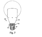
図7は、本発明の原理に従った1つのエジソン型取り付け白熱電球を示す。その白熱電球150は、その白熱電球150内の複数のLEDを制御するための、図1に示されるシステムのようなシステムを含み得て、そして図2A及び図2Bを参照して前述した技術に従って動作し得る。白熱電球150は、AC白熱電球と用いられるハウジングのような、通常の照明器具との使用に適したハウジング155を含み得る。そして、ハウジング155は、LEDがそのハウジング155を通して照明するのを可能にするため一端に光透過性材料を含む。図7の実施形態において、白熱電球150は、ねじ込み口金160、及び白熱電球150の本体に組み込まれているダイヤル形式のインターフェース165を含む。ダイヤルは、矢印170により示されるように、回転され、白熱電球150の動作のためのモード及びパラメータを選択し得る。 FIG. 7 shows one Edison mounted incandescent bulb according to the principles of the present invention. The
図8は、本発明の原理に従った1つのエジソン型取り付け白熱電球を示す。その白熱電球180は、図7の白熱電球150に似ているが、異なるインターフェースを有する。白熱電球180のユーザ・インターフェースは、サムホイール185及び2方向スイッチ190を含む。この実施形態においては、2方向スイッチ190を用いて一連の使用可能なモードとなるように前後に移動し得る。例えば、白熱電球180が1から4の番号が付された4つのモードを有する場合、図8において2方向スイッチ190を左にスライドすることにより、モードは、1モード上に、例えば、モード1からモード2に移動し得る。図8において2方向スイッチ190を右にスライドすることにより、モードは、1モード下に、例えばモード2からモード1に移動し得る。2方向スイッチ190は、その2方向スイッチ190を、力が付与されない中立位置に戻るよう1つ又はそれより多いバネを含み得る。サムホイール185は、単一の方向にエンドレスに回転するよう構成され得て、その場合、サムホイール185により制御されるパラメータは、最大値に達した後に最小値にリセットし得る(又はその逆にし得る)。サムホイールは、1と2分1回転のような事前定義されたスパンを有するよう構成され得る。この後者のケースにおいては、スパンの1つの行き過ぎは、最小パラメータ値を表し、スパンの他方の行き過ぎは、最大パラメータ値を表すようにし得る。一実施形態においては、2方向スイッチ190は、モード(左)及びパラメータ(右)を制御し得て、そしてサムホイール185は、白熱電球180の明るさを制御し得る。 FIG. 8 illustrates one Edison mounted incandescent bulb in accordance with the principles of the present invention. The
図8の白熱電球180のような白熱電球はまた、従来の照明制御システムを介して制御するよう適合され得る。多くの白熱光照明システムは、印加電圧の変化を通して、典型的には印加電圧に対する変化を通してか又はAC波形をチョッピングするかのいずれかを通して、実行される調光制御を有する。電力変換器を白熱電球180内で用いて、受信電力を、可変振幅のAC信号の形式であれ、又はチョップされた波形の形式であれ、制御回路及びLED、及び適切な場合ディジタル部品に対して一定のDC電力供給を維持するために必要な電力に変換することができる。アナログ/ディジタル変換器を含み、AC波形をディジタル化しそしてLEDのための適切な制御信号を発生し得る。白熱電球180はまた、電力供給信号を検出し解析し、そしてLED出力に対する適切な調整を行い得る。例えば、白熱電球180は、110VAC、60Hz電源に接続されようとも、又は220VAC、50Hz電源に接続されようとも、一貫した照明を提供するようプログラムされ得る。 An incandescent bulb, such as the
LEDの制御は、受信したAC信号を例えば適切なLED出力に相関させるルックアップ・テーブルを通して実行され得る。ルックアップ・テーブルは、フル輝度制御信号を含み得て、そしてこれらの制御信号は、パワー調光器が100%であるときLEDに通信され得る。ルックアップ・テーブルの一部分は、80%輝度制御信号を含み得て、そしてランプへの入力電圧が最大値の80%に低減されたとき用いられ得る。プロセッサは、入力電圧が変化するにつれ、プログラムを用いて、パラメータを連続的に変え得る。照明命令を用いて、照明システムからの照明を調光し、並びに、色、光のパターン、照明効果、又はLEDのための任意の他の命令を発生することができるであろう。この技術は、照明装置のイネテリジェントな調光をすること、従来のパワー調光制御装置、及びワイヤリングをインターフェースとして用いて色変化効果を生成すること、又は他の照明効果を生成することのため用いることができるであろう。一実施形態において、色変化と調光との両方が同時に起こり得る。これは、白熱光調光システムをシミュレートするのに有効であり得て、そこでは、白熱光の色温度は、パワーが低減されるにつれ一層暖かくなる。 Control of the LEDs can be performed through a look-up table that correlates the received AC signal, for example, with the appropriate LED output. The look-up table can include full brightness control signals, and these control signals can be communicated to the LED when the power dimmer is 100%. A portion of the look-up table can include an 80% brightness control signal and can be used when the input voltage to the lamp is reduced to 80% of the maximum value. The processor may continuously change the parameters using the program as the input voltage changes. The lighting command could be used to dim the lighting from the lighting system, as well as generate a color, light pattern, lighting effect, or any other command for the LED. This technology is for intelligent dimming of lighting devices, conventional power dimming control devices, and using wiring as an interface to generate color change effects, or other lighting effects. Could be used. In one embodiment, both color change and dimming can occur simultaneously. This can be useful for simulating an incandescent light dimming system, where the color temperature of the incandescent light becomes warmer as power is reduced.
3方向白熱電球も照明レベルを変える共通の装置である。これらのシステムは、白熱電球の口金上に2つの接点を用い、そして白熱電球は、2接点を持つ特別の電気ソケットに装着される。ソケット上のスイッチをターンすることにより、口金のどちらかの接点が電圧と接続され得るか、又は口金の両方が電圧と接続され得る。ランプは、異なる抵抗の2つのフィラメントを含み、3レベルの照明を提供する。図8の白熱電球180のような白熱電球は、3方向白熱電球ソケットと用いるよう適合され得る。白熱電球180は口金上の2つの接点を有することができるであろうし、そして白熱電球180内のルックアップ・テーブル、プログラム、又は他のシステムは、ソケット・セッティングに相関する制御信号を含むことができるであろう。再び、これは、照明制御、色制御、又はLEDのための任意の他の所望の制御のため用いられることができるであろう。 A three-way incandescent bulb is also a common device that changes the illumination level. These systems use two contacts on the base of the incandescent bulb, and the incandescent bulb is mounted in a special electrical socket with two contacts. By turning a switch on the socket, either contact of the base can be connected to the voltage, or both bases can be connected to the voltage. The lamp contains two filaments of different resistance and provides three levels of illumination. An incandescent bulb, such as the
このシステムを用いて、標準照明装置が前に用いられていた範囲において様々な照明効果を生成するため用いられることができるであろう。ユーザは、既存の白熱電球を、本明細書に記載されたLED照明装置と置換することができ、そして、壁上の調光器を用いて部屋内の色変化効果を制御することができるであろう。色変化効果は、調光、前述の色変化効果のうちのいずれか、又は任意の他の色変化、又は変化しない色付け効果を含み得る。 With this system, a standard lighting device could be used to produce a variety of lighting effects in the range previously used. The user can replace the existing incandescent bulb with the LED lighting device described herein, and can use the dimmer on the wall to control the color change effect in the room. I will. The color change effect may include dimming, any of the color change effects described above, or any other color change, or a coloration effect that does not change.
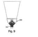
図9は、本発明の原理に従った白熱電球を示す。図9において見られるように、白熱電球200は、直流電力システムと用いられ得るMR−16低電圧取付け具210のような、エジソン型取り付け具とは異なる取付け具から動作し得る。 FIG. 9 illustrates an incandescent bulb in accordance with the principles of the present invention. As seen in FIG. 9, the
図10は、本発明の原理に従った壁ソケット取り付け型照明装置(wall socket mounted light)を示す。照明装置210は、例えば、ANSI仕様に従って構成される110ボルト交流アウトレット220に適合されたプラグを含み得る。照明装置210は、ユーザ・インターフェース230としてスイッチ及びサムホイール、及びアウトレット220に挿入するよう適合された1つ又はそれより多いスペード(spade)240を含み得る。照明装置210の本体は、色が変化する壁ウオッシング効果(color changing wall washing effects)のため光を壁上に指向させるための反射表面を含み得る。 FIG. 10 illustrates a wall socket mounted light according to the principles of the present invention. The
図11は、本発明の原理に従った1つの終夜灯を示す。終夜灯242は、例えば、110ボルト交流アウトレット246に適合されたプラグ244を含み得る。終夜灯242は、その終夜灯242内の複数のLEDを制御するため、図1に示されたシステムのようなシステムを含み得て、そして図2A及び図2Bを参照して前述した技術に従って動作し得る。終夜灯242は、LEDからの光を、例えば下方向に指向させるための光透過性材料248を含み得る。終夜灯242はまた、低い周囲照明を検出するためのセンサ250を含み得て、それにより終夜灯242が低い照明条件が存在したときのみ付勢され得る。センサ250は、プロセッサへの信号を発生して、終夜灯242の付勢及び表示タイプを制御し得る。終夜灯242はまた、前述した季節的照明表示が実行され得るような、クロック/カレンダを含み得る。終夜灯242は、モード及びパラメータを選択するための、前述したもののようなサムホイール260及びスイッチ270を含み得る。上記の実施形態のうちの幾つかと同様に、終夜灯242は、その終夜灯242の制御回路に対して適切なDC電力を発生する変換器を含み得る。 FIG. 11 illustrates one overnight lamp according to the principles of the present invention. The
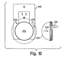
図12は、本発明の原理に従った1つの終夜灯を示す。終夜灯320は、例えば、110ボルト交流アウトレット340に適合されたプラグ330を含み得る。終夜灯320は、その終夜灯320内の複数のLEDを制御するため、図1に示されたシステムのようなシステムを含み得て、そして図2A及び図2Bを参照して前述した技術に従って動作し得る。終夜灯320は、光透過性ドーム345を含み得る。終夜灯320はまた、低い周囲照明を検出するための、光透過性ドーム345内のセンサを含み得て、それにより終夜灯320が低い照明条件が存在するとき自動的に付勢され得る。終夜灯320はまた、前述した季節的照明表示が実行され得るような、クロック/カレンダを含み得る。図12の実施形態において、終夜灯320の光透過性ドーム345はまた、ユーザ・インターフェースとして動作し得る。光透過性ドーム345を第1の矢印330の方向に押すことにより、モードが選択され得る。光透過性ドーム345を第2の矢印355の方向に回転させることにより、パラメータが、そのモード内で選択され得る。上記の実施形態のうちの幾つかと同様に、終夜灯320は、その終夜灯320の制御回路に対して適切なDC電力を発生する変換器を含み得る。 FIG. 12 shows one overnight lamp according to the principles of the present invention. The overnight light 320 may include a
前述の例から認められるように、図1及び図2A及び図2Bを参照して説明されたLEDシステムのようなLEDシステムは、様々な照明応用に、白熱電球、ハロゲン電球、タングステン電球、蛍光電球等々を含む従来の白熱電球に対する交換としても、又は机上ランプ、花瓶(vase)、終夜灯、ランタン、ペーパ・ランタン、設計者終夜灯、ストリップ・ライト、コーブ照明具、MR照明具、壁照明具、ねじ込み口金型照明具、溶岩ランプ(lava lamp)、球体(orb)、机上ランプ、装飾用ランプ、ストリング・ライト(string light)、又はキャンプ照明具のような一体化した照明器具としてのいずれにも適合され得る。システムは、台所照明、浴室照明、寝室照明、娯楽センタ照明、プール及び温泉照明、屋外歩行路照明、パティオ照明、建物照明、建物正面照明、水槽照明、又は光が美的効果のため採用され得る他の範囲における照明を含む建築化照明に対する応用を有し得る。システムは、スプリンクラー、芝生マーカ(lawn markers)、プール・フロート、階段マーカ、グラウンド内マーカ、又はドア・ベルにおける屋外で、又はより一般的に汎用照明、装飾用照明、及び屋内又は屋外現場におけるアクセント照明のため用いられることができるであろう。システムはまた、ブレーキ灯、ダッシュボード照明、又は他の自動車及び乗り物応用におけるような機能的照明が希望されるところに配置され得る。 As will be appreciated from the foregoing examples, LED systems, such as the LED system described with reference to FIGS. 1 and 2A and 2B, are suitable for various lighting applications, such as incandescent bulbs, halogen bulbs, tungsten bulbs, fluorescent bulbs. As a replacement for conventional incandescent bulbs, including, etc. or desk lamps, vases, night lights, lanterns, paper lanterns, designer night lights, strip lights, cove lights, MR lights, wall lights , Screw-in die illuminators, lava lamps, spheres (orbs), desk lamps, decorative lamps, string lights, or as integrated lighting fixtures such as camping lights Can also be adapted. The system can be used for kitchen lighting, bathroom lighting, bedroom lighting, entertainment center lighting, pool and hot spring lighting, outdoor walkway lighting, patio lighting, building lighting, building front lighting, aquarium lighting, or others where light can be employed for aesthetic effects Can have applications for architectural lighting, including lighting in the range of The system can be used outdoors in sprinklers, lawn markers, pool floats, stair markers, in-ground markers, or doorbells, or more generally for general lighting, decorative lighting, and accents in indoor or outdoor scenes Could be used for lighting. The system can also be placed where functional lighting is desired, such as in brake lights, dashboard lighting, or other automotive and vehicle applications.
色変化照明効果を、本明細書に記載された複数の照明装置の間で連係して働かせ得る。連係して働く効果は、従来の照明制御機構を用いて達成され得て、そこでは、例えば、複数の照明装置の各照明装置が、異なって、又は異なる開始時間でもって、又はパワーオン信号に対して、又は従来の家庭又は産業照明設備を介して配信される調光器制御信号に応答するようプログラムされる。 The color change lighting effect may work in tandem between the lighting devices described herein. The effect of working in concert can be achieved using conventional lighting control mechanisms, where, for example, each lighting device of a plurality of lighting devices has a different or different start time, or a power-on signal. Or programmed to respond to dimmer control signals delivered via conventional home or industrial lighting equipment.
各照明装置は、代わりに、その動作を制御するため有線又は無線ネットワークを介して個々にアドレス指定され得る。LED照明装置は、遠隔の制御装置と通信するため、又は有線又は無線ネットワークを介して通信するため送受信器を有し得る。 Each lighting device can instead be individually addressed via a wired or wireless network to control its operation. The LED lighting device may have a transceiver to communicate with a remote control device or to communicate via a wired or wireless network.
特定の照明応用は、LEDの特定の選定を必要とする場合があることが認められるであろう。事前パッケージされたLEDは一般的に、表面実装パッケージ又はTパッケージである。表面実装LEDは、非常に大きなビーム角度を有し、その角度で、光強度は最大光強度の50%に降下し、そしてTパッケージは、幾つかのビーム角度で使用可能であり得る。狭いビーム角度は更に、隣接LED間での比較的小さい色混合でもって投射する。このある一定のLEDの局面は、異なる色を同時に投射するため、又は他の効果をもたらすため採用され得る。より広い角度は、広いビーム角度Tパッケージを用いること、表面実装LEDを用いること、パッケージしないLEDを用いること、チップ・オンボード技術を用いること、又は発明の名称が「発光半導体のための光学的システム(Optical Systems for Light Emitting Semiconductors)」の米国仮特許出願No.60/235,966に記載されているように基板上に直接ダイを取り付けることのような多くの方法で達成されることができるが、これらの方法は本発明を限定するものではない。反射器がまた、照明を所定のパターンで投射するよう1つ又はそれより多いLEDと関連付けされ得る。広ビーム角度光源を用いる利点の1つは、光が集められ、そしてビームが壁に沿って拡散するのを可能にしながら壁上に投射されることができることである。これは、別個のLEDから投射された色が一様の色を与えるよう混合しながら照明を壁上に集中させる望ましい効果を達成する。 It will be appreciated that certain lighting applications may require a specific selection of LEDs. The prepackaged LED is typically a surface mount package or a T package. Surface mounted LEDs have a very large beam angle, at which the light intensity drops to 50% of the maximum light intensity, and the T package may be usable at several beam angles. Narrow beam angles also project with relatively little color mixing between adjacent LEDs. This certain LED aspect may be employed to project different colors simultaneously or to provide other effects. A wider angle can be achieved by using a wide beam angle T package, using surface mount LEDs, using unpackaged LEDs, using chip-on-board technology, or the name of the invention is “Optical for Light Emitting Semiconductors”. System (Optical Systems for Light Emitting Semiconductors) ", US provisional patent application no. While this can be accomplished in many ways, such as mounting the die directly on the substrate as described in 60 / 235,966, these methods do not limit the invention. A reflector may also be associated with one or more LEDs to project the illumination in a predetermined pattern. One advantage of using a wide beam angle light source is that the light can be collected and projected onto the wall while allowing the beam to diffuse along the wall. This achieves the desired effect of focusing the illumination on the wall while mixing so that the colors projected from the separate LEDs give a uniform color.
図13は、少なくとも1つのLED1202を備える照明装置1200を図示する。色のための照明の強度又はビーム幅、又はそれら両方の組み合わせを増大するように、異なる色の複数のLED1202、又は各LEDが単一の色の複数のLED1202があり得る。前部1208及び後部1210を含む反射器がまた、照明装置1200に含まれ、光をLEDから投射する。この反射器は、幾つかの又は1個の反射性材料として形成されることができる。反射器は、少なくとも1つのLED1202から照明を所定の方向に、又は所定のビーム角度を介して指向させ得る。反射器はまた、少なくとも1つのLED1202により拡散された照射を集めて投射し得る。他の例と同様に、照明装置1200は、光透過性材料1212、ユーザ・インターフェース1214及びプラグ1216を含み得る。 FIG. 13 illustrates a
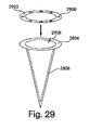
図14は、本発明の原理に従った壁ウオッシング照明装置(wall washing light)の別の実施形態を示す。終夜灯1300は、光透過性材料から形成された光学部品1302、及び着脱可能な光学部品1304を含み得る。着脱可能な光学部品1304は、矢印1306に示されるように、光学部品1302の上に取り外し可能で且つ交換可能に嵌められて、フィルタリング、拡散、焦点合わせ等々を含み得る照明効果を与え得る。着脱可能な光学部品1304は、終夜灯1300からの照射を所定の形状又は像に指向させ、又は照明のスペクトルをプリズムで分光したように広げ得る。着脱可能な光学部品1304は、例えば、鋸歯、スリット、プリズム、回折格子、正方形、三角形、ハーフトーン・スクリーン、円、半円、星、又は任意の他の幾何学的パターンを含むエッチングされたパターンを有し得る。そのパターンはまた、木、星、月、太陽、クローバ、又は任意の他の対象物パターンのような対象物パターンの形式であることができるが、それらに限定されない。着脱可能な光学部品1304はまた、ホログラフィー・レンズであり得る。着脱可能な光学部品1304はまた、像を歪ませ又は再形成するよう構成されたアナモフィック・レンズであり得る。これらのパターンはまた、壁と光学部品との間の幾何学的関係が前もって知られているならば、投影された光が歪みのないパターンを壁上に形成するように形成されることができる。パターンは、壁投影を補償するよう設計されることができるであろう。アナモフィック・レンズを適用する技術は、例えば、「アナモフィック技術及び写真技術−容易に元通りにすることができる歪みの検討(Anamorphic Art and Photography−Deliberate Distortions That Can Be Easily Undone)」(Optics and Photonics News、1992年11月刊行)に記載されており、その教示は本明細書に援用されている。着脱可能な光学部品1304は、多層型レンズを含み得る。多層型レンズにおける複数のレンズのうちの少なくとも1つのレンズはまた、調整可能であり、ユーザに調整可能な照明パターンを提供することができるであろう。 FIG. 14 illustrates another embodiment of a wall washing lighting device in accordance with the principles of the present invention. The
図15は、本発明の原理に従った照明装置を示す。照明装置1500は、前述の照明装置のいずれかであり得る。照明装置は、表示スクリーン1502を含み得る。表示スクリーン1502は、LCD、プラズマ・スクリーン、バックライト・ディスプレイ、エッジライト・ディスプレイ(edgelit display)、単色スクリーン、カラー・スクリーン、スクリーン、又は任意の他のタイプのディスプレイのような任意のタイプのディスプレイ・スクリーンであることができるが、これらに限定されない。表示スクリーン1502は、日の時刻、照明装置1500のためのモード又はパラメータ値、モードの名前、バッテリ充電指示、又は照明装置1500のユーザに有用な任意の他の情報のようなユーザのための情報を表示することができるであろう。モードの名前は、「ストローブ」、「静止」等々のような一般的名前、又は深紅色の照明に対して「ハーバード」、又は青黄色フェード又はウオッシュに対して「ミシガン」のような風変わりな名前であり得る。他の名前は、1年の時刻、休日又は特定の祝典に関連するモードに対して与えられ、そして表示され得る。1日の時刻、1年の残りの日、又は任意の他の情報を含む他の情報が表示され得る。表示情報は文字に限定されず、表示スクリーン1502は、画像又は任意の他の情報を示すことができるであろう。表示スクリーン1502は、図1のプロセッサ2の制御下で動作し得る。照明装置1500は、例えば、表示スクリーン1502を制御するため、又は表示スクリーン1502により表示される時間又は他の情報を設定するため、又はモード又はパラメータ値を選択するためのユーザ・インターフェース1504を含み得る。 FIG. 15 illustrates a lighting device according to the principles of the present invention. The
照明装置1500はまた、ネットワークと関連付けされ、そしてネットワーク信号を受け取り得る。ネットワーク信号は、終夜灯に様々な色を投射し並びに表示スクリーン1502に情報を示すよう指図することができるであろう。例えば、照明装置は、ワールド・ワイド・ウェブから信号を受け取り、そして色又は投影パターンを、受け取った情報に基づいて変えることができるであろう。照明装置は、ウェブ又は他の装置から外部の温度データを受け取り、そして色をその温度に基づいて投影することができるであろう。温度が低温になればなる程、照明は一層飽和した青になり、そして温度が上昇するつれ、照明装置1500は赤の照明を投影し得る。情報は、温度情報に限定されない。情報は、送信されそして受信されることができる任意の情報であることができるであろう。別の例は、株価のような任意の金融情報である。株価が上昇したとき、投射された照明は緑に変わり得て、そして株価が降下するとき、投射された照明は赤に変わり得る。株価が所定の値より下に落ちる場合、照明装置1500は、赤の光をストローブし、又は他の指示効果をなし得る。 The
データを受け取り且つ解釈し、そして応答的な色変化照明効果を生成する、前述したシステムのようなシステムは民生電子機器のような範囲における広い応用を持ち得ることが認められるであろう。例えば、情報は、獲得され、解釈され、そして、クロック無線、電話機、コードレス電話機、ファクシミリ機械、ブーム・ボックス、ミュージック・ボックス、ステレオ、コンパクト・ディスク・プレーヤ、DVDプレーヤ、MP3プレーヤ、カセット・プレーヤ、ディジタル・テープ・プレーヤ、カー・ステレオ、テレビジョン、ホーム・オーディオ・システム、ホーム・シアター・システム、サラウンド音響システム、スピーカ、カメラ、ディジタル・カメラ、ビデオ・レコーダ、ディジタル・ビデオ・レコーダ、コンピュータ、個人用携帯情報機器(PDA)、ページャー、セルラ電話機、コンピュータ・マウス、コンピュータ周辺機器、又はオーバヘッド・プロジェクタのような装置における情報の提供型照明効果に変換される。 It will be appreciated that systems such as those described above that receive and interpret data and generate responsive color change lighting effects can have wide application in a range such as consumer electronics. For example, information is acquired, interpreted, and clock radio, telephone, cordless telephone, facsimile machine, boom box, music box, stereo, compact disc player, DVD player, MP3 player, cassette player, Digital tape player, car stereo, television, home audio system, home theater system, surround sound system, speaker, camera, digital camera, video recorder, digital video recorder, computer, personal Information is converted into information-providing lighting effects in devices such as personal digital assistants (PDAs), pagers, cellular telephones, computer mice, computer peripherals, or overhead projectors.
図16は、モジュラー型ユニットを図示する。照明装置1600は、1つ又はそれより多いLED、及び照明器具の装飾部分を含み得る。インターフェース・ボックス1616は、照明装置1600を動作させるため、プロセッサ、メモリ、制御回路、及びACをDCに変換する電源を含み得る。インターフェース・ボックス1616は、電力接続部1608に接続される標準電力配線部1610を有し得る。インターフェース・ボックス1616は、標準接続ボックス1602に直接嵌合するよう設計されることができる。インターフェース・ボックス1616は、照明装置1600の裏側1604上の接続部と整合するための物理的接続デバイス1612を有することができるであろう。物理的接続デバイス1612を用いて、照明装置1600を壁の上に物理的に取り付けることができるであろう。インターフェース・ボックス1616はまた、電力を照明装置1600にもたらすための1つ又はそれより多い電気的接続部1614を含むことができるであろう。電気的接続部1614は、データをインターフェース・ボックス1616に送るための、又はさもなければインターフェース・ボックス1616又は照明装置1600と通信するための接続部を含み得る。接続部1614及び1612は、照明装置1600の裏側1604上の接続部と整合することができるであろう。これは、照明装置1600の組み立て及び変更を容易にするであろう。これらのシステムは、標準様式で配列されて照明装置1600の容易な変更を可能にする接続部1612及び1614を有することができるであろう。照明装置1600がまた回路の一部又は全部を含むことができるであろうことは当業者に明らかであろう。 FIG. 16 illustrates a modular unit. The
照明装置1600はまた、情報を送信及び受信するための送信器及び受信器を含むことができるであろう。これを用いて、幾つかの照明装置1600を連係して働かせ、又は同期させることができるであろう。表示スクリーン1620及びインターフェース1622を備える制御ユニット1618がまた、幾つかの照明装置1600のモード、及び幾つかの照明装置1600間の連係を設定するため設けられることができるであろう。制御ユニット1618は、照明装置1600を遠隔で制御することができるであろう。制御ユニット1618は、部屋の遠い範囲に置かれ、そして1つ又はそれより多い照明装置1600と通信することができるであろう。その通信は、RF、IR、マイクロ波、音響、電磁波、ケーブル、ワイヤ、ネットワーク、又は他の通信方法のような任意の通信方法を用いて達成されることができるであろうが、それらに限定されるものではない。各照明装置1600はまたアドレス指定可能なコントローラを有し、それにより複数の照明装置1600の各々は、制御ユニット1618により、任意の適切な有線又は無線ネットワークを介して個々にアクセスされ得る。 The
図17は照明装置のためのモジュラー・トポロジーを示す。このモジュラー形態においては、照明エンジン1700は、ワイヤのような複数の電力接続部1704、ワイヤのような複数のデータ接続部1706、及び複数のLED1708、並びにハウジング1710に包囲されている、図1及び図2A及び図2Bを参照して説明された他の構成要素を含み得る。照明エンジン1700は、照明器具に、又はスタンドアローン装置として用いられ得る。モジュラー形態は、照明設計者、建築家、請負人、専門技術者、ユーザ又は照明を設計又は設備する他の人々が用いるのに適している。なお、それらの者は、所定のデータ及び電力配線を設備全体にわたり与え、そして照明エンジン1700をその中の任意の都合良い位置に配置し得る。 FIG. 17 shows a modular topology for the lighting device. In this modular form, the
光学部品を用いて、照明装置の性能を変え又は増強し得る。例えば、反射器を用いて、米国特許出願No.60/235,966「発光半導体用光学システム(Optical Systems for Light Emitting Semiconductors)」に記載されているように、LEDの放射の向きを再度変えるため用いられ得る。なお、上記米国特許出願の教示は本明細書に援用されている。米国特許出願No.60/235,966が本明細書に援用されている。 Optical components can be used to alter or enhance the performance of the lighting device. For example, using a reflector, US patent application no. 60 / 235,966 "Optical Systems for Light Emitting Semiconductors" can be used to re-orient the LED's radiation again, as described in 60 / 235,966 "Optical Systems for Light Emitting Semiconductors". It should be noted that the teachings of the above US patent applications are incorporated herein. US patent application no. 60 / 235,966 is incorporated herein by reference.
図18は、本明細書に開示されているシステムと使用され得る反射器を示す。図18に示されているように、輪郭を描いた反射表面1802は、複数のLED1804から離れて置かれ、そのためLED1804からの放射は、矢印1806により示されるように、反射表面1802に指向される。この形態において、LED1804からの放射は、反射表面1802の周りで円形状で向きを変えられる。反射表面1802は、投影効果を生成するための不完全部又は設計部の範囲を有し得る。LED1804は、光を反射器上へ一様に投影するよう配置されることができ、又はそれらは、反射器のある一定の部分上での照明を増大するよう偏りを有して配置されることができる。複数のLED1804の個々のLED1804はまた、独立に制御されることができる。この技術を用いて、光のパターン又は色効果を生成することができる。 FIG. 18 illustrates a reflector that can be used with the system disclosed herein. As shown in FIG. 18, the outlined reflective surface 1802 is placed away from the plurality of
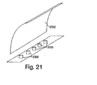
図19は、LED1900が矢印1903に示されるように一般的放物面反射器1902に指向される反射器設計を図示する。一般的放物面反射器1902は、LED1900からの放射に更に焦点を合わせ、又は再度向きを変えるため隆起した中心部1904を含み得る。第2のLED1906により示されるように、第2の一般的放物面反射器1908及び第2の矢印1910が示され、そして隆起した中心部1904がある形態においては省かれ得る。反射表面を用いた、この形態における、又は本明細書に説明された他の形態におけるLED1900は、任意のパッケージの中に、又はパッケージなしの状態であり得ることが認められるであろう。パッケージが設けられない場合、LEDは、動作用電力を与えるn側及びp側に電気的に接続され得る。図20に示されるように、1列のLED2000は、平面の反射表面2002に指向され得て、その平面の反射表面2002は、1列のLED2000を2つの反対の平面方向に指向する。図21に示されるように、1列のLED2100は平面的な表面2102に指向され得て、その平面的な表面2102は1列のLED2100を1つの平面方向に指向する。 FIG. 19 illustrates a reflector design in which the
図1を参照して説明されたシステムのようなシステムは、ボールのような玩具に組み込まれ得る。制御回路、電源及びLEDは、ボールの内部でつり下げられ、又は取り付けられ得て、ボールの外面の全部又は一部は、LEDの色変化効果を見るのを可能にする光透過性材料から形成される。外面の別個の部分は、異なる種類の光透過性材料から形成され得るか、又は異なるグループのLEDにより照明されて、ボールの外面の異なる領域にわたり異なる要領で照明されたボールの外面を提供し得る。 A system such as the system described with reference to FIG. 1 can be incorporated into a toy such as a ball. The control circuit, power supply and LED can be suspended or mounted inside the ball, and all or part of the outer surface of the ball is formed from a light transmissive material that allows to see the color change effect of the LED. Is done. Separate portions of the outer surface may be formed from different types of light transmissive materials or illuminated by different groups of LEDs to provide the outer surface of the ball illuminated in different ways over different regions of the outer surface of the ball. .
ボールは、自律的に動作して、色変化効果を発生し得て、又は制御回路と関連した付勢スイッチからの信号に応答し得る。付勢スイッチは、力、加速度、温度、運動、キャパシタンス、近接度、ホール効果、又は任意の他の刺激又は環境条件又は変数に応答し得る。 The ball may operate autonomously, generate a color change effect, or respond to a signal from an energizing switch associated with the control circuit. The bias switch may be responsive to force, acceleration, temperature, motion, capacitance, proximity, Hall effect, or any other stimulus or environmental condition or variable.
ボールは、1つ又はそれより多い付勢スイッチを含むことができ、そして制御ユニットは、異なる色変化効果を有する異なるスイッチに応答するよう事前プログラムされることができる。ボールは、ランダムに選択された色変化効果を、又は所定の順序の色変化効果の1つを有する入力に応答し得る。2つ又はそれより多いスイッチがボールに組み込まれた場合、LEDは、個々のスイッチ信号又はそれらの組み合わせに従って付勢され得る。これを用いて、例えば、単一のスイッチが付勢されたとき微妙な効果を、又は複数のスイッチが付勢されたとき劇的な効果を有するボールを生成することができるであろう。 The ball can include one or more activation switches, and the control unit can be preprogrammed to respond to different switches having different color change effects. The ball may respond to an input having a randomly selected color change effect or one of a predetermined order of color change effects. If two or more switches are incorporated in the ball, the LEDs can be energized according to individual switch signals or combinations thereof. This could be used, for example, to produce a ball that has a subtle effect when a single switch is activated or a dramatic effect when multiple switches are activated.
ボールは、トランスデューサ信号に応答し得る。例えば、1つ又はそれより多い速度又は加速度トランスデューサは、ボールの運動を検出することができるであろう。これらのトランスデューサを用いて、ボールは、それがより早く又はより遅く回転するにつれて照明効果を変えるようプログラムされ得る。ボールはまた、印加された力の変化量に応答して、異なる照明効果をもたらすようプログラムされ得る。多くの他の有効なトランスデューサ、及びそれらを色変化のボールに採用する方法がある。 The ball may respond to the transducer signal. For example, one or more velocity or acceleration transducers could detect ball motion. With these transducers, the ball can be programmed to change the lighting effect as it rotates faster or slower. The ball can also be programmed to produce different lighting effects in response to changes in applied force. There are many other effective transducers and ways to employ them in color change balls.
ボールは送受信器を含み得る。ボールは、送受信器を介して受信されたデータに応答して、色変化効果を発生し得るか、又は送受信器を用いて、制御又は状態情報をネットワーク又は他の装置に与え得る。送受信器を用いることにより、ボールはゲームに用いられ得て、そのゲームでは、幾つかのボールが互いに通信し、又はボールは他の装置と通信し、又はネットワークと通信する。次いで、ボールは、これらの他の装置又はネットワーク信号を更なる制御のため開始することができるであろう。 The ball may include a transceiver. The ball may generate a color change effect in response to data received via the transceiver, or the transceiver may be used to provide control or status information to the network or other device. By using the transceiver, the ball can be used in a game, where several balls communicate with each other, or the balls communicate with other devices or with a network. The ball would then be able to initiate these other devices or network signals for further control.
ゲームをプレーする方法は、ボールが照明される又は特定の色に照明されるまでプレーを始めないと定義することができるであろう。照明信号は、送受信器を介して通信することによりプレー範囲の外側からもたらすことができ、そしてプレーは、ボールが色を変え、又は類似の信号を通してターン・オフされるとき停止することができるであろう。ボールがゴールを通るとき、ボールは、色を変え、又は点滅し、又は他の照明効果をなすことができるであろう。多くの他のゲーム、又はゲーム中の効果は、ボールが余りに早く移動する又は停止するときボールが色を変える場合に発生され得る。プレーに対する色変化効果は、送受信器により受信された信号に応答し、又はボールの中のスイッチ及び/又はトランスデューサ、又はこれらのある組み合わせに応答し得る。ゲーム・ホット・ポテト(game hot potato)は、外部信号により割り込まれないにしろ、あるいは割り込まれるにしろ、ボールが連続的に色を変える場合プレーされることができるだろうし、そしてそれが赤に又はある他の事前定義された色に突然に又は徐々に変わるとき、あなたはボールを別の人に投げなければならない。ボールは、検出デバイスを有することができ、それによりボールが所定の期間内に投げられない場合それはストローブのような照明効果を開始する。本発明のボールは、球形、フットボール形状、又は任意の他のゲーム又は玩具のボールのような形状のような様々な形状を有し得る。 A method of playing a game could be defined as not playing until the ball is illuminated or illuminated to a specific color. The lighting signal can be brought from outside the playing range by communicating via a transceiver, and play can be stopped when the ball changes color or is turned off through a similar signal. I will. As the ball passes the goal, the ball will be able to change color or flash or make other lighting effects. Many other games, or in-game effects, can be generated when the ball changes color when the ball moves or stops too quickly. The color change effect on play may be responsive to signals received by the transceiver, or may be responsive to switches and / or transducers in the ball, or some combination thereof. Game hot potatoes can be played if the ball continuously changes color, whether or not interrupted by an external signal, and it turns red Or when it suddenly or gradually changes to some other predefined color, you must throw the ball to another person. The ball can have a detection device whereby it initiates a strobe-like lighting effect if the ball is not thrown within a predetermined period of time. The ball of the present invention may have various shapes, such as a sphere, a football shape, or any other game or toy ball-like shape.
前述の例から認められるように、図1及び図2A及び図2Bを参照して説明されたLEDシステムのようなLEDシステムは、様々な色変化玩具及びゲームに適合され得る。例えば、色変化効果は、玩具の銃、水鉄砲、玩具の車、こま、ジャイロスコープ、ダーツボード、自転車、自転車の車輪、スケートボード、列車セット、電気レーシング・カー・トラック、玉突き台、盤上で行うゲーム、ホット・ポテト・ゲーム、光射撃ゲーム(shooting light game)、魔法の杖、玩具の刀、アクションの容姿(action figure)、玩具のトランク、玩具のボート、スポーツ衣類及び装備、光るスティック、万華鏡、又は磁石を含む多くのゲーム及び玩具に有効に組み込まれ得る。色変化効果はまた、ビューマスター(View Master)、スーパーボール(Super Ball)、ライトブライト(Lite Brite)、ハリーポッター(Harry Potter)の魔法の杖、又はティンカーベル(Tinker Bell)の魔法の杖のようなブランドのある玩具に有効に組み込まれ得る。 As can be appreciated from the foregoing example, an LED system, such as the LED system described with reference to FIGS. 1 and 2A and 2B, can be adapted to various color changing toys and games. For example, color change effects can be found on toy guns, water guns, toy cars, tops, gyroscopes, dartboards, bicycles, bicycle wheels, skateboards, train sets, electric racing car trucks, ball platforms, boards Playing games, hot potato games, lighting shooting games, magic wands, toy swords, action figures, toy trunks, toy boats, sports clothing and equipment, glowing sticks, It can be effectively incorporated into many games and toys including kaleidoscopes or magnets. The color change effect can also be found in the View Master, Super Ball, Light Brite, Harry Potter magic wand, or Tinker Bell magic wand. Can be effectively incorporated into such branded toys.
図22は、内部照明回路を有する本発明の原理に従った装置の一実施形態のブロック図である。装置2200は、図1及び図2A及び図2Bを参照して説明されたシステムのようなシステムを含み得る着用可能なアクセサリである。装置2200は本体2201を有し、その本体2201はプロセッサ2202、駆動回路2204、1つ又はそれより多いLED2206及び電源2208を含む。装置2200は、インターフェースとして働く入力/出力2210を任意に含み得て、そのインターフェースによりプログラミングが受け取られて、装置2200の動作を制御する。本体2201は、光透過性部分を含み得て、その光透過性部分は、LED2206からの光が本体2201から流出するのを可能にするため透過性、半透明、又は半透明且つ拡散性である。LED2206は、例えば、適切な拡散材料の外側表面に沿って取り付けられ得る。LED2206は、拡散材料の端部に又はその後ろに沿って目立たないように配置され得る。表面実装LEDは、拡散材料の内側表面上で本体2201に対して直接固定され得る。 FIG. 22 is a block diagram of one embodiment of an apparatus according to the principles of the present invention having an internal lighting circuit.
入力/出力2210は、ボタン、ダイヤル、スライダ、スイッチ、又は信号を装置2200に与えるための前述の任意の他の装置のような入力装置を含み得るか、又は入力/出力2210は、ユニバーサル・シリアル・バス(USB)接続部、シリアル接続部、又は任意の他のワイヤード接続部を含み得るか、又は入力/出力2210は、赤外線又は無線周波数送受信器のような無線接続のための送受信器を含み得る。一実施形態において、着用可能なアクセサリは、他の着用可能なアクセサリと入力/出力2210を介して通信して、ある多数のアクセサリの間で同期された照明効果を生成するよう構成され得る。無線伝送のため、入力/出力2210は、例えば、赤外線又はマイクロ波信号を用いて、基地の送受信器と通信して、DMX又は類似の通信信号を送信し得る。次いで、自律的アクセサリは、この信号を受信し、そして信号の中の情報を適用して、照明効果を変え、それにより、照明効果は、基地の送信器位置から制御されることができるであろう。この技術を用いて、幾つかのアクセサリは、基地送信器から同期され得る。次いで、情報はまた、照明効果の変化と関連するアクセサリ間に伝達されることができるであろう。一例示においては、入力/出力2210は、AbacomのTXMシリーズ・デバイスのような送信器を含み得て、そのAbacomのTXMシリーズ・デバイスは、小さく、低パワーであり、且つ400MHzのスペクトルを用いている。そのようなネットワークを用いて、異なる人々の上の複数のアクセサリは、色を人から人へ弾むように移動させること、又は幾人かの人々に跨った同時且つ同期された効果を含む興味有る効果を与えるよう同期されることができる。同じ人の上でのある一定数のアクセサリはまた、連係された色変化効果を与えるよう同期され得る。本発明の原理に従ったシステムは、本明細書に記載されたようにネットワークを介して制御され得る。そのネットワークは、個人の、ローカルの、広範囲の、又は他のネットワークであり得る。ブルートウース標準(Blue Tooth standard)は、任意のプロトコルを用いることができるにも拘わらずそのようなシステムと通信するとき、適切なプロトコルであり得る。 Input /
入力/出力2210は、環境測定値(温度、周囲音又は光)、生理学的データ(心拍数、身体の温度)、又は他の測定可能な量のためのセンサを含み得て、そしてこれらのセンサ信号を用いて、これらの測定値の関数である色変化効果をもたらし得る。 Input /
宝飾品及び衣類を含む様々な装飾的装置を色及び光に対して形を与えるため用いることができる。例えば、これらは、ネックレス、ティアラ、帽子、ブローチ、ベルトのバックル、カフリンクス、ボタン、ピン、リング、又はブレスレット、アンクレット等の形を取ることができるであろう。本体2201に、又は本体、アイコン、ロゴ、ブランドを有するイメージ、キャラクタ、及び記号(アンパーサンド、ドル符号、及び音符)の光透過性部分に対する形状の幾つかの事例が有る。他の所で注記されたように、システムはまた、着用可能な又は着用可能でないことがあり得る照明された装飾用プレート又は墓石の符号のような他の応用に適合され得る。 A variety of decorative devices can be used to give shape to color and light, including jewelry and clothing. For example, they could take the form of necklaces, tiaras, hats, brooches, belt buckles, cuff links, buttons, pins, rings, or bracelets, anklets and the like. There are several examples of shapes for the
図23は、外部照明回路を有する本発明の原理に従った装置の一実施形態の概略図である。図23に示されるように、着用可能なアクセサリ2300は、1つ又はそれより多いLED2304を含む着用可能なアクセサリのような第1のハウジング2302を含み得る。プロセッサ2306、制御器2308、電源2310及び入力/出力2312を含む照明回路は、第1のハウジング2302の外にあり、そして第2のハウジング2314に含まれている。リンク2316は、照明回路が駆動信号を第1のハウジング2302内のLED2304に通信し得るように設けられている。この形態は、第1のハウジング2302が例えばシャツのボタンにおけるように、遠隔の回路に接続され得る小さいアクセサリ又は他の着用可能なアクセサリである応用に好都合であり得る。LED2304を除く照明回路の全てが第1のハウジング2302の外に示されているが、1つ又はそれより多い構成要素が第1のハウジング2302内に含まれるようにしてもよいことが認められるであろう。 FIG. 23 is a schematic diagram of one embodiment of an apparatus according to the principles of the present invention having an external lighting circuit. As shown in FIG. 23, the
図24は、本発明の原理に従った自律的に色変化する靴を図示する。靴2400は、主要部2402、ヒール2404、つま先部2406及び靴底2408を含む。主要部2402は、人の足を収容するよう適合されており、そして靴を使用するに適した任意の材料で作られ得る。ヒール2404は、半透明で光拡散性の材料で形成され得て、そしてその中に、図1及び図2A及び図2Bを参照して説明されたシステムのようなシステムが埋め込まれ得る。自律的色変化能力を持つヒール2404に加えて、又はそれの代わりに、つま先部2406、靴底2408、又は任意の他の部分のような靴2400の別の部分は、自律的色変化システムを含み得る。各々が入力/出力システムを含み、それにより右と左の靴の両方が互いに通信して、同期した色変化効果を達成するようにした、1対の靴が提供され得る。靴2400の一実施形態においては、回路は、その靴2400の靴底2408内に配置され得て、そしてヒール2404又はつま先部2406又はそれら両方内に配置される、LEDを駆動するためのワイヤを有する。 FIG. 24 illustrates an autonomously color changing shoe in accordance with the principles of the present invention. The
前述の例から認められるように、本明細書に開示されたシステムは、様々な着用可能で装飾用の物体に対して広い適用を有し得る。このシステムを採用する衣類は、コート、シャツ、パンツ、着物、靴、履き物、運動用衣類、アクセサリ、宝飾品、バックパック、ドレス、帽子、ブレスレット、傘、ペットの首輪、旅行カバン、及び旅行カバン・タグを含み得る。本明細書に開示されたシステムを採用する装飾用物体は、額縁、文鎮、ギフト・カード、弓、及び贈答用包みを含み得る。 As can be appreciated from the foregoing examples, the system disclosed herein may have wide application for a variety of wearable and decorative objects. Clothing that employs this system includes coats, shirts, pants, kimonos, shoes, footwear, sports clothing, accessories, jewelry, backpacks, dresses, hats, bracelets, umbrellas, pet collars, travel bags, and travel bags. -It may contain tags. Decorative objects that employ the systems disclosed herein may include picture frames, paperweights, gift cards, bows, and gift wraps.
色変化するバッジ及び他の衣類は、ある一定の環境において特定の効果を有し得る。例えば、バッジには、透明な、半透明な、又は他の材料を設けることができ、そして1つ又はそれより多いLEDは、その材料を照明するよう配置されることができる。一実施形態において、バッジは、少なくとも1つの赤、1つの青、1つの緑を含むであろうし、そしてLEDは、その材料を端部から照明するよう配置されるであろう。材料はパターンを有し得て、それによりパターンが光を反射するようにする。パターンは、材料にエッチングされ得て、それによりパターンは、材料を走行する光を反射し、そしてパターンが輝くように見える。LEDの3色が与えられるとき、多くの色変化効果を生成することができる。これは、人目を引く効果を生成し得て、そして小売り環境で、貿易展示会で、商品及びサービスを販売するとき、又は人自身に注意を引くことが有効であり得る任意の他の状況において、バッジを着けている人に注意を向けさせること、即ち有効な注意を獲得する人にすることができる。 Color changing badges and other garments can have specific effects in certain circumstances. For example, the badge can be provided with a transparent, translucent, or other material, and one or more LEDs can be arranged to illuminate that material. In one embodiment, the badge will include at least one red, one blue, one green, and the LED will be arranged to illuminate the material from the end. The material can have a pattern, thereby causing the pattern to reflect light. The pattern can be etched into the material so that the pattern reflects light traveling through the material and the pattern appears to shine. Many color-changing effects can be generated when three colors of LEDs are given. This can generate eye-catching effects and in retail environments, at trade exhibitions, when selling goods and services, or in any other situation where it may be useful to draw attention to the person himself , Direct attention to the person wearing the badge, that is, the person who obtains effective attention.
バッジを端部から照明してエッチングされたパターンを照明する原理は、端部照明掲示板のような他の装置に同様に適用されることができる。1列のLEDは、材料を端部照明するよう配列され得て、そしてその材料はパターンを有し得る。材料は、1つ又はそれより多い側部上で照明され、そして反射性材料を反対の端部に用いて、光がその端部で逃げるのを防止し得る。反射性材料はまた、表面照明を均一にする傾向を有する。これらの装置はまた、端部照明に代わって又はそれに加えて、バックライトされ、又は材料を通して照明されることができる。 The principle of illuminating the etched pattern by illuminating the badge from the edge can be similarly applied to other devices such as edge illuminated bulletin boards. A row of LEDs can be arranged to end illuminate the material, and the material can have a pattern. The material may be illuminated on one or more sides and a reflective material may be used at the opposite end to prevent light from escaping at that end. The reflective material also has a tendency to make the surface illumination uniform. These devices can also be backlit or illuminated through material instead of or in addition to edge lighting.
図25は、本発明に従った1つのLED装置を図示する。LED装置2500は、プロセッサ2502及び1つ又はそれより多いLED2504を、図1及び図2A及び図2Bを参照して説明された構成のような構成で含み得る。LED装置2500は、光透過性材料から形成されたアイシクル(icicle)との使用に適合され得る。アイシクルは、プラスチック、ガラス、又は他の材料から形成された模造品アイシクルであり得て、そして非常に現実的に詳細な様式で、又は非常にフォルム化され抽象的様式で与えられ得る。多数の色変化アイシクルが以下に説明される。 FIG. 25 illustrates one LED device according to the present invention. The
図26は照明型アイシクル2600を図示し、そこで図1及び図2A及び図2Bを参照して説明されたLED照明装置のようなLED照明装置2602を用いてアイシクル2604を照明し得る。アイシクル2604は、半透過性材料、半透明材料、透明材料、プラスチック、紙、ガラス、氷、凍結液体、又はアイシクルを形成し且つLED放射を伝搬するに適した任意の他の材料のような材料から形成されることができるであろう。アイシクル2604は、中空であり得るか、又は光透過性材料から形成された中実体であり得る。LED照明装置2602からの照明は、アイシクル2604に指向され、そしてアイシクル2604と結合される。アイシクルの材料は、様々な照明効果を与える不完全部(imperfections)を有し得る。1つのそのような効果は、主に透過性のある材料が不完全部のパターンを含むとき生成される。その不完全部は、その材料を通過又はそれに沿って通る光の方向を変えさせ得て、明るいスポット又は範囲が照明された材料の中に現れるようにさせる。これらの不完全部がパターンに設定される場合、パターンは明るく見える一方、他の範囲は明るく見えないであろう。不完全部はまた、アイシクル2604の表面を実質的に一様に覆って、霜で覆われた様相を生成することができる。アイシクル2604の表面を実質的に一様に覆う一様に照明されるアイシクルの効果を生成し得る。 FIG. 26 illustrates an illumination-
アイシクル2604は、照明を与えるため1つ又はそれより多いLEDを用いて照明されることができる。1個のLEDを用いた場合、アイシクル2604は、変化する強度を有する単一の色でもって照明されることができるか、又はその強度は固定にし得る。一実施形態においては、照明型アイシクル2600は2以上のLEDを含み、そして別の実施形態においては、LEDは様々な色である。異なった色のLEDを有する照明型アイシクル2600を設けることにより、照明型アイシクル2600の色相、色の飽和度(彩度)及び輝度を変えることができる。2つ又はそれより多いLEDを用いて、加法的な色(additive color)を与えることができる。2つのLEDを回路を有する照明型アイシクル2600に用いて、各色をオン又はオフする場合、どのLEDも付勢されていないときの黒を含めて4つの色が生成されることができるであろう。3つのLEDを照明型アイシクル2600に用い、そして各LEDが3つの強度設定を有する場合、33、即ち27の色選択が使用可能である。一実施形態においては、LED制御信号は、8ビット(=128の組み合わせ)の解像度を有するPWM信号であろう。3つの異なった色のLEDを用いることにより、これは、128^3又は16.7×100万個の使用可能な色を与える。The
図27は、ネットワークを共用する複数のアイシクルを示す。複数の照明型アイシクル2700は、各々、前述のネットワークのいずれかのようなネットワーク2702を介して通信するためのネットワーク・インターフェースを含む。ネットワーク2704は、照明制御信号を複数の照明型アイシクル2700のそれぞれに供給し得る。なお、その複数の照明型アイシクル2700のそれぞれは、一義的にアドレス指定可能であり得る。照明型アイシクル2700が一義的にアドレス指定可能でない場合、制御情報は、照明型アイシクル2700の全てに同報通信され得る。コンピュータ又は前述の任意の他の制御装置のような制御データ・ソース2706は、制御情報を照明型アイシクル2700にネットワーク送受信器2708及びネットワーク2704を介して供給し得る。照明型アイシクル2700の1つがまたマスター・アイシクルとして動作して、制御情報を、スレーブ・アイシクルである他の照明型アイシクル2700に供給することができるであろう。ネットワーク2704を一般的に用いて、複数の照明型アイシクルから連係された又は連係されてない色変化照明効果を発生し得る。 FIG. 27 shows a plurality of icicles sharing a network. The plurality of illuminated
複数の照明型アイシクル2700のうちの1つ又はそれより多い照明型アイシクルはまた、スタンドアローン・モードで動作し、そして他の照明型アイシクル2700とは別個の色変化効果を発生し得る。照明型アイシクル2700は、ネットワーク2704を介して、例えば、様々な全面色(different solid colors)、ゆっくり変化する色、早く変化する色、ストロービング光のようなユーザにより選択されるべき複数の照明制御ルーチン、又は任意の他の照明ルーチンを用いてプログラムされることができるであろう。セレクタ・スイッチを用いて、プログラムを選択することができるであろう。プログラムを選択する別の方法は、電力をアイシクルにオンし、次いで所定の時間期間内に戻るようオンすることになるであろう。例えば、不揮発性メモリを用いて、電力が遮断される前にアイシクルが動作していた最後のプログラムをアイシクルが覚えておくようにすることができるであろう。キャパシタを用いて、信号線を10秒間高に保ち、そして電力がこの期間内に循環された場合、システムは、次のプログラムにスキップするようプログラムされることができるであろう。電力の周期が10秒より多く要する場合、キャパシタは、高信号レベルより下に放電し、そして前のプログラムは、システムを再度付勢した際に再度呼び出される。プログラム又は動作のモードを循環させる他の方法は、知られており、そして本明細書に記載されたシステムに適切に適合され得る。 One or more illuminated icicles of the plurality of illuminated
図28は、フランジ2802を有するアイシクル2800を図示する。フランジ2802は、アイシクル2800の容易な取り付けを可能にし得る。一実施形態において、フランジ2802を用いて、それにより、そのフランジは棚部(ledge)2808と結合する一方、アイシクル2800の残りの部分は棚部2808により形成された孔にかかる。この装着の方法は、アイシクルが既存の孔にかかる場合、又はアイシクル2800が表示されるべき範囲に孔が作られることができる場合有効である。他の装着方法は、知られており、そして本発明と使用するよう適合され得る。 FIG. 28 illustrates an
図29は、本発明の原理に従ったアイシクルを示す。複数のLED2900が、リング2902に配設され得る。リング2902は、アイシクル2906のフランジ2904に係合され得る。このように配列された場合、LED2900は、アイシクル2906を透過される照明を放射し得る。LED2900がフランジ2904に直接結合するようにリング2902の形状及び寸法が作られる場合、アイシクル2906は端部から照明されるであろう。リング2902は、代わりに、フランジ2904の直径より小さくし得て、それによりLED2900は、アイシクル2906の中の中空空洞2908の中に、又はアイシクル2906が中実な材料から形成される場合アイシクル2906の頂部表面上に放射する。 FIG. 29 illustrates an icicle according to the principles of the present invention. A plurality of
図30は中実なアイシクル3000を図示し、その中実なアイシクル3000は、ロッドの形式又は任意の他の適切な形式であり得て、1つ又はそれより多いLED3002が中実なアイシクル3000の中に光を投影するよう位置決めされている。 FIG. 30 illustrates a
図31は、本発明の原理に従ったロープ照明装置(rope light)を図示する。ロープ照明装置3100は、図1及び図2A及び図2Bを参照して与えられた説明に従った複数のLED又はLEDサブシステム3102を含み得る。一実施形態においては、異なる色の3つのLEDダイは、各LEDサブシステム3102に一緒にパッケージされ得て、各ダイは個々に制御可能である。複数のこれらのLEDサブシステム3102は、可撓性で且つ半透明のチューブ3104の内部に配設され得る。LEDサブシステム3102は、チューブ3104に沿って、例えば、約15.24cm(6インチ)の一様間隔で離間され、そしてチューブ3104の軸3106に沿って向けられている。LEDサブシステム3102は、前述のシステム及び方法のいずれかを介して制御され得る。一実施形態において、ある一定数のLEDサブシステム3102は共通信号により制御され得て、それにより数フィート(約30cmの5〜7倍)又はそれより長いチューブ3104の長さが色を一度に変えるように見える。チューブ3104は、ロープ、又は他の円筒状材料又は物体に似せて作られ得る。LEDサブシステム3102は、チューブ3104内にリング又は他の幾何学的又は非対称のパターンで配設され得る。LEDサブシステム3102はまた、前述のように、チューブ3104を端部照明するよう整列されることができるであろう。フィルタ又はフィルムが、チューブ3104の外側表面又は内側表面上に設け得て、快い視覚的効果を生成し得る。 FIG. 31 illustrates a rope illuminator according to the principles of the present invention. The rope illuminator 3100 may include a plurality of LEDs or
他の消費者製品は、本明細書に説明されたシステム及び方法を用いて実現され得る。金槌は釘を打つことに応答して色変化効果を発生し得て、台所タイマは時間のカウントダウンに応答して色変化効果を発生し得て、ペンはそれを用いて書く動作に応答して色変化効果を発生し得て、又は電気缶切りは付勢されたとき色変化効果を発生し得る。本発明が示された好適な実施形態と関係して開示されそして詳細に記載されたが、その様々な変更及び改良が、当業者にとって容易に明らかとなるであろう。従って、本発明の趣旨及び範囲は、特許請求の範囲によってのみ制限されるべきである。 Other consumer products may be implemented using the systems and methods described herein. A hammer can generate a color change effect in response to hitting a nail, a kitchen timer can generate a color change effect in response to a time countdown, and a pen in response to a writing action using it A color change effect can be generated, or an electric can opener can generate a color change effect when energized. While the invention has been disclosed and described in detail in connection with the preferred embodiments shown, various changes and modifications thereof will become readily apparent to those skilled in the art. Therefore, the spirit and scope of the present invention should be limited only by the claims.
Claims (21)
少なくとも1つの照明プログラムを格納するメモリと、
前記メモリに結合され、前記メモリに格納された少なくとも1つの照明プログラムを実行し、且つ前記実行される少なくとも1つの照明プログラムに基づいて少なくとも1つの制御信号を出力するプロセッサと、
前記プロセッサに結合され、前記少なくとも2つのLEDのうちの少なくとも1つのLEDに供給される電力を少なくとも1つの制御信号に基づいて独立して制御する少なくとも1つの制御器と、
前記プロセッサの動作を制御するユーザ・インターフェースであって、ユーザが次の動作:
前記プロセッサにより実行するための、前記メモリに格納された所望の照明プログラムを選択すること、および
少なくとも1つの照明プログラムの実行を修正すること、
のうちの少なくとも1つを行うことを可能にするよう適合されているユーザ・インターフェースと、
を備える照明装置であって、
各LEDは複数の強度設定を有し、
前記制御器の配置は、前記少なくとも2つのLEDの相対強度を制御するようになされ、
前記装置は材料をさらに備え、該材料の構成は、前記複数のLEDから放射された光を受け取り、前記複数のLEDの少なくとも2つの異なるスペクトルの組み合わせである色を材料に表示させるようになされており、
前記ユーザ・インターフェースは、前記プロセッサから遠隔の位置に配置され、
前記プロセッサは、前記照明プログラムを用いて白熱光調光システムをシミュレートするために、当該照明装置への入力電圧に応じて各LEDを個別に調光制御することにより、前記光の色温度変化と調光との両方を同時に行い、前記光の色温度が、当該照明装置への前記入力電圧が低減されるにつれて一層暖かくなるように構成される、
照明装置。
At least two LEDs adapted to generate at least two different spectra;
A memory for storing at least one lighting program;
A processor coupled to the memory, executing at least one lighting program stored in the memory, and outputting at least one control signal based on the executed at least one lighting program;
At least one controller coupled to the processor and independently controlling power supplied to at least one of the at least two LEDs based on at least one control signal;
A user interface for controlling the operation of the processor, wherein the user performs the following operations:
Selecting a desired lighting program stored in the memory for execution by the processor, and modifying execution of at least one lighting program;
A user interface adapted to allow performing at least one of:
A lighting device comprising:
Each LED has multiple intensity settings,
The controller is arranged to control the relative intensity of the at least two LEDs;
The apparatus further comprises a material configured to receive light emitted from the plurality of LEDs and cause the material to display a color that is a combination of at least two different spectra of the plurality of LEDs. And
The user interface is located remotely from the processor;
In order to simulate an incandescent light dimming system using the lighting program, the processor performs dimming control on each LED individually according to the input voltage to the lighting device, thereby changing the color temperature of the light. thus both the bets dimming simultaneously, the color temperature of the light is configured to be more warm as the input voltage to the lighting device is reduced,
Lighting device.
前記実行される少なくとも1つの照明プログラムは、前記プロセッサにより実行されたとき照明効果を少なくとも1つの調整可能なパラメータに従ってLEDに生成させるよう構成されており、
前記ユーザ・インターフェースは、ユーザが前記実行される少なくとも1つの照明プログラムの少なくとも1つの調整可能なパラメータを調整するのを可能にするよう適合されている
請求項1に記載の照明装置。
The at least one lighting program executed includes at least one adjustable parameter;
The at least one lighting program executed is configured to cause the LED to generate a lighting effect according to at least one adjustable parameter when executed by the processor;
The lighting device of claim 1, wherein the user interface is adapted to allow a user to adjust at least one adjustable parameter of the executed at least one lighting program.
The lighting device of claim 1, wherein the user interface comprises a single button.
The lighting device of claim 1, wherein the user interface comprises two buttons.
The lighting device of claim 1, wherein the user interface includes adjustable user input.
The lighting device according to claim 1, wherein the user interface includes at least one of a button, a dial, a slider, a knob, a switch, a variable switch, a variable selector, and a keypad.
前記少なくとも1つの動的照明プログラムは、前記プロセッサにより実行されたとき、動的照明効果を少なくとも1つの調整可能なパラメータに従ってLEDに生成させるよう構成されており、
前記ユーザ・インターフェースは、ユーザが前記少なくとも1つの動的照明プログラムの少なくとも1つの調整可能なパラメータを調整するのを可能とするよう適合されている
請求項1から6のいずれか一項に記載の照明装置。
The at least one lighting program executed comprises at least one dynamic lighting program having at least one adjustable parameter;
The at least one dynamic lighting program is configured to cause the LED to generate a dynamic lighting effect according to at least one adjustable parameter when executed by the processor;
7. The user interface according to any one of claims 1 to 6, wherein the user interface is adapted to allow a user to adjust at least one adjustable parameter of the at least one dynamic lighting program. Lighting device.
請求項1から7のいずれか一項に記載の照明装置。
The user interface is adapted to output at least one of a logic high signal and a logic low signal to the processor, the processor receiving at least one signal from the memory upon receiving a signal output by the user interface. one of the illumination device according to any one of claims 1 to 7, which is adapted to select a lighting program.
前記プロセッサは、前記ユーザ・インターフェースにより出力された信号を受け取ると前記少なくとも1つの照明プログラムの少なくとも1つのパラメータを調整するよう適合されている
請求項1から8のいずれか一項に記載の照明装置。
The user interface is adapted to output at least one of a logic high signal and a logic low signal to the processor;
Wherein the processor is lighting device according to any one of the claims 1 which is adapted to receive a signal output by the user interface for adjusting at least one parameter of the at least one lighting program 8 .
前記プロセッサは、所定の持続時間を有する前記ユーザ・インターフェースにより出力された信号を受け取ると前記少なくとも1つの照明プログラムの少なくとも1つのパラメータを調整するよう適合されている
請求項1から9のいずれか一項に記載の照明装置。
The processor further comprises a timer that measures the duration of the signal output by the user interface;
Wherein the processor any of claims 1 which is adapted to receive a signal output by the user interface for adjusting at least one parameter of the at least one lighting program 9 one having a predetermined duration The lighting device according to item.
The lighting device of claim 10 , wherein the processor is adapted to continuously change at least one parameter until a signal output by the user interface changes.
前記少なくとも2つのLEDを実質的に包囲する第2のハウジングと、を更に備え、
前記材料が、前記第2のハウジングの少なくとも一部分を形成する
請求項1に記載の照明装置。
A first housing substantially enclosing the processor, memory and controller;
A second housing substantially enclosing the at least two LEDs;
Said material, the lighting device according to claim 1 for forming at least a portion of the second housing.
The lighting device according to claim 1 , wherein the material includes at least one of a translucent material, a translucent material, a light diffusion material, and a transmissive material.
The controller includes at least one of a pulse width modulator, a pulse amplitude modulator, a pulse displacement modulator, a resistance ladder, a current source, a voltage source, a voltage ladder, a switch, a transistor, and a voltage controller. The illumination device according to any one of 1 to 13 .
前記プロセッサは、エンコーダ信号を受け取ると、少なくとも1つの照明プログラムを選択することと少なくとも1つの照明プログラムの少なくとも1つのパラメータを調整することとのうちの少なくとも1つを実行するよう適合されている
請求項1から14のいずれか一項に記載の照明装置。
The user interface comprises an encoder for outputting an encoder signal;
The processor is adapted to perform at least one of selecting at least one lighting program and adjusting at least one parameter of the at least one lighting program upon receiving an encoder signal. Item 15. The lighting device according to any one of Items 1 to 14 .
前記ユーザ・インターフェースは、アナログ信号を発生するよう適合され、
前記アナログ/ディジタル変換器は、アナログ信号をディジタル信号に変換するよう構成され、
前記ディジタル信号は、前記照明装置の動作の際に前記プロセッサに通信される
請求項1から15のいずれか一項に記載の照明装置。
An analog / digital converter;
The user interface is adapted to generate an analog signal;
The analog / digital converter is configured to convert an analog signal to a digital signal;
16. A lighting device according to any one of the preceding claims, wherein the digital signal is communicated to the processor during operation of the lighting device.
17. The lighting device according to any one of claims 1 to 16 , further comprising a power converter for providing power to at least one of the processor and the at least two LEDs.
Communication between the user interface and the processor is achieved through at least one of electromagnetic transmission, radio frequency transmission, infrared transmission, microwave transmission, acoustic transmission, wired transmission, cable transmission and network transmission. Item 18. The lighting device according to any one of Items 1 to 17 .
19. The receiver of claim 1, further comprising a receiver associated with the processor that receives at least one of electromagnetic transmission, radio frequency transmission, infrared transmission, acoustic transmission, wired transmission, cable transmission, and network transmission. The lighting device described in 1.
少なくとも1つの照明プログラムを格納するメモリと、
前記メモリに結合され、前記メモリに格納された少なくとも1つの照明プログラムを実行し、且つ前記実行される少なくとも1つの照明プログラムに基づいて少なくとも1つの制御信号を出力するプロセッサと、
前記プロセッサに結合され、前記少なくとも2つのLEDのうちの少なくとも1つのLEDに供給される電力を少なくとも1つの制御信号に基づいて独立して制御する少なくとも1つの制御器と、
を備える照明装置であって、
各LEDは複数の強度設定を有し、
前記制御器の配置は、前記少なくとも2つのLEDの相対強度を制御するようになされ、
前記装置は材料をさらに備え、該材料の構成は、前記複数のLEDから放射された光を受け取り、前記複数のLEDの少なくとも2つの異なるスペクトルの組み合わせである色を材料に表示させるようになされており、
前記プロセッサは、前記照明プログラムを用いて白熱光調光システムをシミュレートするために、当該照明装置への入力電圧に応じて各LEDを個別に調光制御することにより、前記光の色温度変化と調光との両方を同時に行い、前記光の色温度が、当該照明装置への入力電圧が低減されるにつれて一層暖かくなるように構成される、
照明装置。
At least two LEDs adapted to generate at least two different spectra;
A memory for storing at least one lighting program;
A processor coupled to the memory, executing at least one lighting program stored in the memory, and outputting at least one control signal based on the executed at least one lighting program;
At least one controller coupled to the processor and independently controlling power supplied to at least one of the at least two LEDs based on at least one control signal;
A lighting device comprising:
Each LED has multiple intensity settings,
The controller is arranged to control the relative intensity of the at least two LEDs;
The apparatus further comprises a material configured to receive light emitted from the plurality of LEDs and cause the material to display a color that is a combination of at least two different spectra of the plurality of LEDs. And
In order to simulate an incandescent light dimming system using the lighting program, the processor performs dimming control on each LED according to an input voltage to the lighting device, thereby changing the color temperature of the light. The color temperature of the light is configured to become warmer as the input voltage to the lighting device is reduced.
Lighting device.
The lighting device according to any one of claims 1 to 20 , further comprising a power connection portion, wherein the power connection portion includes at least one of a plug, a two-pin metal plate, and a screw cap.
Applications Claiming Priority (7)
| Application Number | Priority Date | Filing Date | Title |
|---|---|---|---|
| US19933300P | 2000-04-24 | 2000-04-24 | |
| US60/199,333 | 2000-04-24 | ||
| US21141700P | 2000-06-14 | 2000-06-14 | |
| US60/211,417 | 2000-06-14 | ||
| US09/805,368 US20030206411A9 (en) | 1997-08-26 | 2001-03-13 | Light-emitting diode based products |
| US09/805,368 | 2001-03-13 | ||
| PCT/US2001/013151 WO2001082657A1 (en) | 2000-04-24 | 2001-04-24 | Light-emitting diode based products |
Related Child Applications (1)
| Application Number | Title | Priority Date | Filing Date |
|---|---|---|---|
| JP2011093193A Division JP5508333B2 (en) | 2000-04-24 | 2011-04-19 | Light-emitting diode-based products |
Publications (3)
| Publication Number | Publication Date |
|---|---|
| JP2003531467A JP2003531467A (en) | 2003-10-21 |
| JP2003531467A5 JP2003531467A5 (en) | 2008-06-19 |
| JP5460940B2 true JP5460940B2 (en) | 2014-04-02 |
Family
ID=27394004
Family Applications (3)
| Application Number | Title | Priority Date | Filing Date |
|---|---|---|---|
| JP2001578157A Expired - Fee Related JP5460940B2 (en) | 2000-04-24 | 2001-04-24 | Light-emitting diode-based products |
| JP2011093193A Expired - Lifetime JP5508333B2 (en) | 2000-04-24 | 2011-04-19 | Light-emitting diode-based products |
| JP2014011181A Expired - Lifetime JP5758020B2 (en) | 2000-04-24 | 2014-01-24 | Light-emitting diode-based products |
Family Applications After (2)
| Application Number | Title | Priority Date | Filing Date |
|---|---|---|---|
| JP2011093193A Expired - Lifetime JP5508333B2 (en) | 2000-04-24 | 2011-04-19 | Light-emitting diode-based products |
| JP2014011181A Expired - Lifetime JP5758020B2 (en) | 2000-04-24 | 2014-01-24 | Light-emitting diode-based products |
Country Status (10)
| Country | Link |
|---|---|
| US (3) | US20030206411A9 (en) |
| EP (3) | EP1422975B9 (en) |
| JP (3) | JP5460940B2 (en) |
| AT (2) | ATE548887T1 (en) |
| AU (1) | AU2001259134A1 (en) |
| DE (1) | DE60141857D1 (en) |
| DK (2) | DK1422975T3 (en) |
| ES (2) | ES2344257T3 (en) |
| PT (2) | PT1422975E (en) |
| WO (1) | WO2001082657A1 (en) |
Families Citing this family (400)
| Publication number | Priority date | Publication date | Assignee | Title |
|---|---|---|---|---|
| US6975079B2 (en) * | 1997-08-26 | 2005-12-13 | Color Kinetics Incorporated | Systems and methods for controlling illumination sources |
| US6777891B2 (en) | 1997-08-26 | 2004-08-17 | Color Kinetics, Incorporated | Methods and apparatus for controlling devices in a networked lighting system |
| US7764026B2 (en) * | 1997-12-17 | 2010-07-27 | Philips Solid-State Lighting Solutions, Inc. | Systems and methods for digital entertainment |
| US20040052076A1 (en) | 1997-08-26 | 2004-03-18 | Mueller George G. | Controlled lighting methods and apparatus |
| US7187141B2 (en) * | 1997-08-26 | 2007-03-06 | Color Kinetics Incorporated | Methods and apparatus for illumination of liquids |
| US6965205B2 (en) * | 1997-08-26 | 2005-11-15 | Color Kinetics Incorporated | Light emitting diode based products |
| US20030133292A1 (en) * | 1999-11-18 | 2003-07-17 | Mueller George G. | Methods and apparatus for generating and modulating white light illumination conditions |
| US7038398B1 (en) * | 1997-08-26 | 2006-05-02 | Color Kinetics, Incorporated | Kinetic illumination system and methods |
| US6548967B1 (en) * | 1997-08-26 | 2003-04-15 | Color Kinetics, Inc. | Universal lighting network methods and systems |
| US7242152B2 (en) * | 1997-08-26 | 2007-07-10 | Color Kinetics Incorporated | Systems and methods of controlling light systems |
| US6720745B2 (en) * | 1997-08-26 | 2004-04-13 | Color Kinetics, Incorporated | Data delivery track |
| US7139617B1 (en) * | 1999-07-14 | 2006-11-21 | Color Kinetics Incorporated | Systems and methods for authoring lighting sequences |
| US7014336B1 (en) * | 1999-11-18 | 2006-03-21 | Color Kinetics Incorporated | Systems and methods for generating and modulating illumination conditions |
| US7385359B2 (en) * | 1997-08-26 | 2008-06-10 | Philips Solid-State Lighting Solutions, Inc. | Information systems |
| US6806659B1 (en) * | 1997-08-26 | 2004-10-19 | Color Kinetics, Incorporated | Multicolored LED lighting method and apparatus |
| US7233831B2 (en) | 1999-07-14 | 2007-06-19 | Color Kinetics Incorporated | Systems and methods for controlling programmable lighting systems |
| WO2001024584A1 (en) * | 1999-09-29 | 2001-04-05 | Color Kinetics, Inc. | Systems and methods for calibrating light output by light-emitting diodes |
| US20020176259A1 (en) | 1999-11-18 | 2002-11-28 | Ducharme Alfred D. | Systems and methods for converting illumination |
| JP4495814B2 (en) * | 1999-12-28 | 2010-07-07 | アビックス株式会社 | Dimmable LED lighting fixture |
| US7049761B2 (en) | 2000-02-11 | 2006-05-23 | Altair Engineering, Inc. | Light tube and power supply circuit |
| US7550935B2 (en) | 2000-04-24 | 2009-06-23 | Philips Solid-State Lighting Solutions, Inc | Methods and apparatus for downloading lighting programs |
| US20050275626A1 (en) * | 2000-06-21 | 2005-12-15 | Color Kinetics Incorporated | Entertainment lighting system |
| US7502034B2 (en) * | 2003-11-20 | 2009-03-10 | Phillips Solid-State Lighting Solutions, Inc. | Light system manager |
| US7202613B2 (en) * | 2001-05-30 | 2007-04-10 | Color Kinetics Incorporated | Controlled lighting methods and apparatus |
| AU2001285408A1 (en) * | 2000-08-07 | 2002-02-18 | Color Kinetics Incorporated | Automatic configuration systems and methods for lighting and other applications |
| US7161556B2 (en) * | 2000-08-07 | 2007-01-09 | Color Kinetics Incorporated | Systems and methods for programming illumination devices |
| US7303300B2 (en) * | 2000-09-27 | 2007-12-04 | Color Kinetics Incorporated | Methods and systems for illuminating household products |
| US7038399B2 (en) * | 2001-03-13 | 2006-05-02 | Color Kinetics Incorporated | Methods and apparatus for providing power to lighting devices |
| US6883929B2 (en) | 2001-04-04 | 2005-04-26 | Color Kinetics, Inc. | Indication systems and methods |
| US7598684B2 (en) * | 2001-05-30 | 2009-10-06 | Philips Solid-State Lighting Solutions, Inc. | Methods and apparatus for controlling devices in a networked lighting system |
| WO2002101702A2 (en) * | 2001-06-13 | 2002-12-19 | Color Kinetics Incorporated | Systems and methods of controlling light systems |
| GB2369730B (en) * | 2001-08-30 | 2002-11-13 | Integrated Syst Tech Ltd | Illumination control system |
| US7604361B2 (en) | 2001-09-07 | 2009-10-20 | Litepanels Llc | Versatile lighting apparatus and associated kit |
| US7331681B2 (en) * | 2001-09-07 | 2008-02-19 | Litepanels Llc | Lighting apparatus with adjustable lenses or filters |
| US6749310B2 (en) * | 2001-09-07 | 2004-06-15 | Contrast Lighting Services, Inc. | Wide area lighting effects system |
| AU2002360721A1 (en) * | 2001-12-19 | 2003-07-09 | Color Kinetics Incorporated | Controlled lighting methods and apparatus |
| US6685339B2 (en) * | 2002-02-14 | 2004-02-03 | Polaris Pool Systems, Inc. | Sparkle light bulb with controllable memory function |
| US20030185020A1 (en) * | 2002-03-28 | 2003-10-02 | All-Line Inc. | LED bulb for night-light |
| US7364488B2 (en) | 2002-04-26 | 2008-04-29 | Philips Solid State Lighting Solutions, Inc. | Methods and apparatus for enhancing inflatable devices |
| ATE416597T1 (en) * | 2002-05-09 | 2008-12-15 | Philips Solid State Lighting | LED DIMMER CONTROL |
| US7358679B2 (en) * | 2002-05-09 | 2008-04-15 | Philips Solid-State Lighting Solutions, Inc. | Dimmable LED-based MR16 lighting apparatus and methods |
| JP2005525897A (en) | 2002-05-13 | 2005-09-02 | エス.シー. ジョンソン アンド サン、インコーポレイテッド | Harmonious fragrance, light and sound generation |
| US6789913B2 (en) * | 2002-06-18 | 2004-09-14 | Meng Pi Wei | Multifunctional shoe flashing device |
| US6822556B2 (en) * | 2002-07-17 | 2004-11-23 | Kidlights, Llc | Methods and apparatus for a multi-mode night-light configured to emulate a traffic signal |
| US7023543B2 (en) * | 2002-08-01 | 2006-04-04 | Cunningham David W | Method for controlling the luminous flux spectrum of a lighting fixture |
| US20050213343A1 (en) * | 2002-08-02 | 2005-09-29 | Xavier Andrew Jablonski | Novelty device |
| US6761323B2 (en) * | 2002-08-20 | 2004-07-13 | Johnny Hsieh | Water jet mechanism with composite control light-emitting modules |
| DK1535495T3 (en) * | 2002-08-28 | 2010-10-11 | Philips Solid State Lighting | Methods and systems for illumination of surroundings |
| US6787999B2 (en) * | 2002-10-03 | 2004-09-07 | Gelcore, Llc | LED-based modular lamp |
| US7300192B2 (en) * | 2002-10-03 | 2007-11-27 | Color Kinetics Incorporated | Methods and apparatus for illuminating environments |
| US7131748B2 (en) * | 2002-10-03 | 2006-11-07 | Year-Round Creations, Llc | Decorative lights with addressable color-controllable LED nodes and control circuitry, and method |
| US7632004B2 (en) * | 2004-07-06 | 2009-12-15 | Tseng-Lu Chien | LED night light with more than 1 optics means |
| ATE387076T1 (en) | 2002-11-19 | 2008-03-15 | Dan Friis | LIGHT BODY OR LIGHT SOURCE BASED ON LIGHT ELEMENT DIODES |
| KR20050103492A (en) | 2003-02-07 | 2005-10-31 | 에스.씨. 존슨 앤드 선, 인코포레이티드 | Diffuser with light emitting diode nightlight |
| US20120150675A1 (en) * | 2003-03-11 | 2012-06-14 | Gabor Lederer | System for the commercialization of electronic candle illumination |
| US20060039137A1 (en) * | 2003-03-11 | 2006-02-23 | Gabor Lederer | System for the commercialization of electronic candle illumination and electronic candle therefor |
| EP1620676A4 (en) * | 2003-05-05 | 2011-03-23 | Philips Solid State Lighting | Lighting methods and systems |
| DE20307358U1 (en) * | 2003-05-13 | 2003-08-28 | Helmstadt Metallwerk | lighting device |
| EP1627556A1 (en) * | 2003-05-19 | 2006-02-22 | Sloanled, Inc. | Multiple led control apparatus and method |
| US10252079B2 (en) * | 2003-06-06 | 2019-04-09 | Koninklijke Philips N.V. | Hand-held light therapy apparatus |
| US7604378B2 (en) * | 2003-07-02 | 2009-10-20 | S.C. Johnson & Son, Inc. | Color changing outdoor lights with active ingredient and sound emission |
| US7066619B2 (en) | 2003-08-29 | 2006-06-27 | Waters Michael A | LED picture light apparatus and method |
| US20070008726A1 (en) * | 2003-09-02 | 2007-01-11 | Brown Richard D | Lighting apparatus with proximity sensor |
| ITMI20031987A1 (en) * | 2003-10-14 | 2005-04-15 | Archimede Elettronica S R L | DEVICE AND METHOD FOR CHECKING THE COLOR OF A LIGHTING SOURCE |
| US7008086B1 (en) * | 2003-10-29 | 2006-03-07 | Curtis Kell | Electronically controlled flashing light and RF transmitter for ice fishing tip-ups |
| US7059070B2 (en) * | 2003-10-31 | 2006-06-13 | Alina Designs, Inc. | Footwear containing improved audio/visual displays |
| US7344279B2 (en) * | 2003-12-11 | 2008-03-18 | Philips Solid-State Lighting Solutions, Inc. | Thermal management methods and apparatus for lighting devices |
| AU2003271383A1 (en) | 2003-12-23 | 2005-07-07 | Hpm Industries Pty Ltd | A Solar Powered Light Assembly to Produce Light of Varying Colours |
| TWM247772U (en) * | 2003-12-26 | 2004-10-21 | Mu-Chin You | LED luminary with remote controller |
| US7254910B2 (en) * | 2004-01-08 | 2007-08-14 | Bbc International, Ltd. | Footwear with externally activated switch |
| US7096607B2 (en) * | 2004-01-08 | 2006-08-29 | Bbc International, Ltd. | Clothing with externally activated switch |
| US10575376B2 (en) | 2004-02-25 | 2020-02-25 | Lynk Labs, Inc. | AC light emitting diode and AC LED drive methods and apparatus |
| WO2011143510A1 (en) | 2010-05-12 | 2011-11-17 | Lynk Labs, Inc. | Led lighting system |
| US10499465B2 (en) | 2004-02-25 | 2019-12-03 | Lynk Labs, Inc. | High frequency multi-voltage and multi-brightness LED lighting devices and systems and methods of using same |
| WO2010138211A1 (en) | 2009-05-28 | 2010-12-02 | Lynk Labs, Inc. | Multi-voltage and multi-brightness led lighting devices and methods of using same |
| US20060221606A1 (en) * | 2004-03-15 | 2006-10-05 | Color Kinetics Incorporated | Led-based lighting retrofit subassembly apparatus |
| EP1754121A4 (en) * | 2004-03-15 | 2014-02-12 | Philips Solid State Lighting | Methods and systems for providing lighting systems |
| US7354172B2 (en) * | 2004-03-15 | 2008-04-08 | Philips Solid-State Lighting Solutions, Inc. | Methods and apparatus for controlled lighting based on a reference gamut |
| US7515128B2 (en) * | 2004-03-15 | 2009-04-07 | Philips Solid-State Lighting Solutions, Inc. | Methods and apparatus for providing luminance compensation |
| US7358706B2 (en) * | 2004-03-15 | 2008-04-15 | Philips Solid-State Lighting Solutions, Inc. | Power factor correction control methods and apparatus |
| US20050259424A1 (en) | 2004-05-18 | 2005-11-24 | Zampini Thomas L Ii | Collimating and controlling light produced by light emitting diodes |
| US7646029B2 (en) * | 2004-07-08 | 2010-01-12 | Philips Solid-State Lighting Solutions, Inc. | LED package methods and systems |
| US7163316B2 (en) * | 2004-08-18 | 2007-01-16 | Jeng-Shyong Wu | Multi-functional ornamental lighting equipment |
| US8013537B2 (en) | 2004-08-20 | 2011-09-06 | Hold IP Limited | Lighting system power adaptor |
| EP1792522A1 (en) * | 2004-09-09 | 2007-06-06 | Philips Intellectual Property & Standards GmbH | Light-generating body |
| CA2579196C (en) * | 2004-09-10 | 2010-06-22 | Color Kinetics Incorporated | Lighting zone control methods and apparatus |
| US7542257B2 (en) * | 2004-09-10 | 2009-06-02 | Philips Solid-State Lighting Solutions, Inc. | Power control methods and apparatus for variable loads |
| US20060062019A1 (en) * | 2004-09-22 | 2006-03-23 | Jean Young | Portable rechargeable night light |
| EP1800523B1 (en) | 2004-10-05 | 2020-05-13 | Signify Holding B.V. | Interactive lighting system |
| US7276854B1 (en) * | 2004-10-13 | 2007-10-02 | Theory3, Inc. | Decorative lamp and lighting system for vehicles |
| EP1653435A1 (en) * | 2004-10-26 | 2006-05-03 | Sony Ericsson Mobile Communications AB | Backlight unit for display device |
| US7238075B2 (en) * | 2004-11-01 | 2007-07-03 | Brodsky Mark A | Personal water activity apparatus with variable light display for protection against sharks and other water-borne predators |
| DE102004061294B4 (en) * | 2004-12-20 | 2020-03-19 | Tridonic Gmbh & Co Kg | Method for programming an operating device for lamps, interface for an operating device for lamps and operating device for lamps |
| US7710369B2 (en) * | 2004-12-20 | 2010-05-04 | Philips Solid-State Lighting Solutions, Inc. | Color management methods and apparatus for lighting devices |
| JP2008527446A (en) * | 2005-01-06 | 2008-07-24 | エス.シー. ジョンソン アンド サン、インコーポレイテッド | Method and apparatus for storing and defining light shows |
| EP1684001A1 (en) * | 2005-01-20 | 2006-07-26 | Christian Niederberger | Lighting device |
| EP2858461B1 (en) * | 2005-01-24 | 2017-03-22 | Philips Lighting North America Corporation | Methods and apparatus for providing workspace lighting and facilitating workspace customization |
| EP1850912A4 (en) * | 2005-02-18 | 2009-07-01 | Lucian Moscovici | Apparatus and method for providing a multi-stage light treatment |
| US8460108B2 (en) * | 2005-02-25 | 2013-06-11 | Microsoft Corporation | Computerized method and system for generating a gaming experience in a networked environment |
| WO2006093889A2 (en) * | 2005-02-28 | 2006-09-08 | Color Kinetics Incorporated | Configurations and methods for embedding electronics or light emitters in manufactured materials |
| US7331688B2 (en) * | 2005-04-29 | 2008-02-19 | Semisilicon Technology Corp. | Synchronous light emitting diode lamp string |
| US7703951B2 (en) * | 2005-05-23 | 2010-04-27 | Philips Solid-State Lighting Solutions, Inc. | Modular LED-based lighting fixtures having socket engagement features |
| US7766518B2 (en) * | 2005-05-23 | 2010-08-03 | Philips Solid-State Lighting Solutions, Inc. | LED-based light-generating modules for socket engagement, and methods of assembling, installing and removing same |
| US8061865B2 (en) | 2005-05-23 | 2011-11-22 | Philips Solid-State Lighting Solutions, Inc. | Methods and apparatus for providing lighting via a grid system of a suspended ceiling |
| WO2006133272A2 (en) | 2005-06-06 | 2006-12-14 | Color Kinetics Incorporated | Methods and apparatus for implementing power cycle control of lighting devices based on network protocols |
| US20180046777A1 (en) * | 2005-07-13 | 2018-02-15 | Nanthealth, Inc. | Night light with embedded cellular modem |
| US20100328099A1 (en) * | 2005-07-13 | 2010-12-30 | Vitality, Inc. | Night Light With Embedded Cellular Modem |
| US7451001B2 (en) * | 2005-07-25 | 2008-11-11 | Ronald Paul Harwood | Method and system of controlling lighting fixture |
| US8090453B1 (en) | 2005-08-23 | 2012-01-03 | Ronald Paul Harwood | Method and system of controlling media devices configured to output signals to surrounding area |
| US7630776B2 (en) * | 2005-08-23 | 2009-12-08 | Ronald Paul Harwood | Method and system of controlling media devices configured to output signals to surrounding area |
| US9071911B2 (en) | 2005-08-23 | 2015-06-30 | Ronald Paul Harwood | Method and system of controlling media devices configured to output signals to surrounding area |
| US7317403B2 (en) * | 2005-08-26 | 2008-01-08 | Philips Lumileds Lighting Company, Llc | LED light source for backlighting with integrated electronics |
| EP1934967B1 (en) | 2005-09-12 | 2012-02-08 | Acuity Brands, Inc. | Light management system having networked intelligent luminaire managers, and applications thereof |
| US7884556B2 (en) * | 2005-09-16 | 2011-02-08 | Advanced Color Lighting, Inc. | Color-changing light array device |
| US7817063B2 (en) | 2005-10-05 | 2010-10-19 | Abl Ip Holding Llc | Method and system for remotely monitoring and controlling field devices with a street lamp elevated mesh network |
| DE102005051270A1 (en) * | 2005-10-26 | 2007-05-03 | Patent-Treuhand-Gesellschaft für elektrische Glühlampen mbH | Circuit arrangement and method for adjusting the brightness of a light source arrangement |
| US8407823B2 (en) * | 2005-10-31 | 2013-04-02 | Sundance Spas, Inc. | Spa with waterfall |
| TWI433588B (en) | 2005-12-13 | 2014-04-01 | Koninkl Philips Electronics Nv | Led lighting device |
| US20070139316A1 (en) * | 2005-12-21 | 2007-06-21 | Sony Ericsson Mobile Communications Ab | Led module with integrated controller |
| US7619370B2 (en) * | 2006-01-03 | 2009-11-17 | Philips Solid-State Lighting Solutions, Inc. | Power allocation methods for lighting devices having multiple source spectrums, and apparatus employing same |
| US20070173314A1 (en) * | 2006-01-26 | 2007-07-26 | Daka Studio Inc. | Sudoku game device with dual control button |
| CA2642028C (en) * | 2006-02-10 | 2013-12-10 | Philips Solid-State Lighting Solutions, Inc. | Methods and apparatus for high power factor controlled power delivery using a single switching stage per load |
| US7439679B2 (en) * | 2006-03-16 | 2008-10-21 | Motorola, Inc. | Method and apparatus for illuminating light sources within an electronic device |
| US8203445B2 (en) | 2006-03-28 | 2012-06-19 | Wireless Environment, Llc | Wireless lighting |
| US9074736B2 (en) | 2006-03-28 | 2015-07-07 | Wireless Environment, Llc | Power outage detector and transmitter |
| US8994276B2 (en) | 2006-03-28 | 2015-03-31 | Wireless Environment, Llc | Grid shifting system for a lighting circuit |
| US11523488B1 (en) | 2006-03-28 | 2022-12-06 | Amazon Technologies, Inc. | Wirelessly controllable communication module |
| US9338839B2 (en) | 2006-03-28 | 2016-05-10 | Wireless Environment, Llc | Off-grid LED power failure lights |
| US9860965B2 (en) | 2006-03-28 | 2018-01-02 | Wireless Environment, Llc | Cloud connected lighting system |
| US8491159B2 (en) | 2006-03-28 | 2013-07-23 | Wireless Environment, Llc | Wireless emergency lighting system |
| US8669716B2 (en) * | 2007-08-30 | 2014-03-11 | Wireless Environment, Llc | Wireless light bulb |
| US8519566B2 (en) | 2006-03-28 | 2013-08-27 | Wireless Environment, Llc | Remote switch sensing in lighting devices |
| US8362713B2 (en) * | 2006-03-28 | 2013-01-29 | Wireless Environment, Llc | Wireless lighting devices and grid-shifting applications |
| US20070236913A1 (en) * | 2006-04-06 | 2007-10-11 | Rain Bird Europe, S.A.R.L. | Lighting Process And Mechanism |
| US7766511B2 (en) | 2006-04-24 | 2010-08-03 | Integrated Illumination Systems | LED light fixture |
| US7543951B2 (en) * | 2006-05-03 | 2009-06-09 | Philips Solid-State Lighting Solutions, Inc. | Methods and apparatus for providing a luminous writing surface |
| US7658506B2 (en) | 2006-05-12 | 2010-02-09 | Philips Solid-State Lighting Solutions, Inc. | Recessed cove lighting apparatus for architectural surfaces |
| US7748878B2 (en) * | 2006-05-18 | 2010-07-06 | Production Resource Group, Inc. | Lighting control system with wireless network connection |
| US20080009220A1 (en) * | 2006-05-22 | 2008-01-10 | Mike Simpson | Test Tube Alien Toy |
| EP2033278B1 (en) * | 2006-05-31 | 2019-04-10 | Cree, Inc. | Lighting device and method of lighting |
| EP2999314B1 (en) * | 2006-06-02 | 2020-11-18 | Signify Holding B.V. | Lamp control circuit and method of driving a lamp |
| WO2007141766A2 (en) * | 2006-06-09 | 2007-12-13 | Koninklijke Philips Electronics N.V. | Control of bath water color with light |
| DE102006028670B4 (en) * | 2006-06-22 | 2018-10-25 | Tridonic Gmbh & Co Kg | Dimmable control gear with internal dimming characteristic, method for compensating tolerances of operating diodes controlled by a control gear and method for configuring a control gear for bulbs |
| EP2036406B1 (en) * | 2006-06-23 | 2011-04-06 | Koninklijke Philips Electronics N.V. | Method and device for driving an array of light sources |
| GB2440784A (en) * | 2006-08-08 | 2008-02-13 | Peter James Bailey | A light patterning system |
| CN101589650B (en) | 2006-10-19 | 2017-04-12 | 飞利浦固体状态照明技术公司 | Networkable led-based lighting fixtures and methods for powering and controlling same |
| KR101460004B1 (en) | 2006-11-10 | 2014-11-10 | 필립스 솔리드-스테이트 라이팅 솔루션스, 인크. | Methods and apparatus for controlling series-connected leds |
| US7729941B2 (en) | 2006-11-17 | 2010-06-01 | Integrated Illumination Systems, Inc. | Apparatus and method of using lighting systems to enhance brand recognition |
| US20080136796A1 (en) * | 2006-11-20 | 2008-06-12 | Philips Solid-State Lighting Solutions | Methods and apparatus for displaying images on a moving display unit |
| EP2087280B1 (en) | 2006-11-28 | 2018-07-18 | Hayward Industries, Inc. | Programmable underwater lighting system |
| ES2436283T3 (en) | 2007-01-05 | 2013-12-30 | Philips Solid-State Lighting Solutions, Inc. | Methods and apparatus for simulating resistive loads |
| US8013538B2 (en) | 2007-01-26 | 2011-09-06 | Integrated Illumination Systems, Inc. | TRI-light |
| DE102007006033A1 (en) * | 2007-02-07 | 2008-08-14 | Recaro Aircraft Seating Gmbh & Co. Kg | Seat control unit |
| US20080224849A1 (en) * | 2007-03-15 | 2008-09-18 | Geno Sirhan | Multifunctional lighting system |
| NZ580402A (en) | 2007-03-30 | 2012-09-28 | Holdip Ltd | A power adaptor for a lighting unit having a solid-state light source and a controller for controlling power draw |
| US8378596B2 (en) * | 2007-04-02 | 2013-02-19 | John Alfred Ayres | Momentary night light assembly |
| US20090020684A1 (en) * | 2007-07-16 | 2009-01-22 | Cheng-Chung Shih | Illumination apparatus and optical radiation control method thereof |
| US8197079B2 (en) * | 2007-07-18 | 2012-06-12 | Ruud Lighting, Inc. | Flexible LED lighting systems, fixtures and method of installation |
| US7915570B2 (en) | 2007-08-03 | 2011-03-29 | National Instruments Corporation | Smart camera with an integrated lighting controller |
| US8742686B2 (en) | 2007-09-24 | 2014-06-03 | Integrated Illumination Systems, Inc. | Systems and methods for providing an OEM level networked lighting system |
| US11317495B2 (en) | 2007-10-06 | 2022-04-26 | Lynk Labs, Inc. | LED circuits and assemblies |
| US11297705B2 (en) | 2007-10-06 | 2022-04-05 | Lynk Labs, Inc. | Multi-voltage and multi-brightness LED lighting devices and methods of using same |
| US10986714B2 (en) | 2007-10-06 | 2021-04-20 | Lynk Labs, Inc. | Lighting system having two or more LED packages having a specified separation distance |
| US10321528B2 (en) | 2007-10-26 | 2019-06-11 | Philips Lighting Holding B.V. | Targeted content delivery using outdoor lighting networks (OLNs) |
| ES2301432B1 (en) * | 2007-10-31 | 2009-08-27 | Roberto Jimenez Postigo | PROGRAMMING DEVICE OF LIGHTING SYSTEMS BASED ON LED DIODES. |
| US9152381B2 (en) | 2007-11-09 | 2015-10-06 | Psyleron, Inc. | Systems and methods employing unique device for generating random signals and metering and addressing, e.g., unusual deviations in said random signals |
| US20090128921A1 (en) * | 2007-11-15 | 2009-05-21 | Philips Solid-State Lighting Solutions | Led collimator having spline surfaces and related methods |
| US8118447B2 (en) | 2007-12-20 | 2012-02-21 | Altair Engineering, Inc. | LED lighting apparatus with swivel connection |
| US7712918B2 (en) | 2007-12-21 | 2010-05-11 | Altair Engineering , Inc. | Light distribution using a light emitting diode assembly |
| US8594976B2 (en) | 2008-02-27 | 2013-11-26 | Abl Ip Holding Llc | System and method for streetlight monitoring diagnostics |
| US7857477B2 (en) * | 2008-04-03 | 2010-12-28 | Bbc Internatinoal Llc | Article of clothing with washable light module |
| US8610376B2 (en) | 2008-04-14 | 2013-12-17 | Digital Lumens Incorporated | LED lighting methods, apparatus, and systems including historic sensor data logging |
| US8823277B2 (en) | 2008-04-14 | 2014-09-02 | Digital Lumens Incorporated | Methods, systems, and apparatus for mapping a network of lighting fixtures with light module identification |
| US10539311B2 (en) | 2008-04-14 | 2020-01-21 | Digital Lumens Incorporated | Sensor-based lighting methods, apparatus, and systems |
| US8805550B2 (en) | 2008-04-14 | 2014-08-12 | Digital Lumens Incorporated | Power management unit with power source arbitration |
| US8368321B2 (en) | 2008-04-14 | 2013-02-05 | Digital Lumens Incorporated | Power management unit with rules-based power consumption management |
| AU2009236311B2 (en) | 2008-04-14 | 2014-06-12 | Osram Sylvania Inc. | Modular lighting systems |
| US8841859B2 (en) | 2008-04-14 | 2014-09-23 | Digital Lumens Incorporated | LED lighting methods, apparatus, and systems including rules-based sensor data logging |
| US8552664B2 (en) | 2008-04-14 | 2013-10-08 | Digital Lumens Incorporated | Power management unit with ballast interface |
| US8373362B2 (en) | 2008-04-14 | 2013-02-12 | Digital Lumens Incorporated | Methods, systems, and apparatus for commissioning an LED lighting fixture with remote reporting |
| US8543249B2 (en) | 2008-04-14 | 2013-09-24 | Digital Lumens Incorporated | Power management unit with modular sensor bus |
| US8610377B2 (en) | 2008-04-14 | 2013-12-17 | Digital Lumens, Incorporated | Methods, apparatus, and systems for prediction of lighting module performance |
| US8339069B2 (en) | 2008-04-14 | 2012-12-25 | Digital Lumens Incorporated | Power management unit with power metering |
| US8754589B2 (en) | 2008-04-14 | 2014-06-17 | Digtial Lumens Incorporated | Power management unit with temperature protection |
| US8531134B2 (en) | 2008-04-14 | 2013-09-10 | Digital Lumens Incorporated | LED-based lighting methods, apparatus, and systems employing LED light bars, occupancy sensing, local state machine, and time-based tracking of operational modes |
| US8866408B2 (en) | 2008-04-14 | 2014-10-21 | Digital Lumens Incorporated | Methods, apparatus, and systems for automatic power adjustment based on energy demand information |
| WO2009132073A2 (en) * | 2008-04-23 | 2009-10-29 | Graphic Packaging International, Inc. | Container having a light source |
| WO2009134885A1 (en) | 2008-04-29 | 2009-11-05 | Ivus Industries, Inc. | Wide voltage, high efficiency led driver circuit |
| US8038321B1 (en) | 2008-05-06 | 2011-10-18 | Koninklijke Philips Electronics N.V. | Color mixing luminaire |
| US8038327B1 (en) | 2008-05-06 | 2011-10-18 | Genlyte Thomas Group Llc | Color mixing luminaire |
| US8255487B2 (en) | 2008-05-16 | 2012-08-28 | Integrated Illumination Systems, Inc. | Systems and methods for communicating in a lighting network |
| US8360599B2 (en) | 2008-05-23 | 2013-01-29 | Ilumisys, Inc. | Electric shock resistant L.E.D. based light |
| US20100114340A1 (en) * | 2008-06-02 | 2010-05-06 | Charles Huizenga | Automatic provisioning of wireless control systems |
| US8364325B2 (en) | 2008-06-02 | 2013-01-29 | Adura Technologies, Inc. | Intelligence in distributed lighting control devices |
| US8275471B2 (en) * | 2009-11-06 | 2012-09-25 | Adura Technologies, Inc. | Sensor interface for wireless control |
| US7839017B2 (en) * | 2009-03-02 | 2010-11-23 | Adura Technologies, Inc. | Systems and methods for remotely controlling an electrical load |
| US9001161B2 (en) * | 2008-06-06 | 2015-04-07 | Dolby Laboratories Licensing Corporation | Chromaticity control for solid-state illumination sources |
| US20090315478A1 (en) * | 2008-06-19 | 2009-12-24 | Mccolgin Jerry L | Lighting system having master and slave lighting fixtures |
| JP5204563B2 (en) * | 2008-06-24 | 2013-06-05 | パナソニック株式会社 | LED lighting device |
| DE102008029816A1 (en) * | 2008-06-24 | 2009-12-31 | Osram Gesellschaft mit beschränkter Haftung | Circuit for dimming a lamp and associated method |
| US8275694B2 (en) * | 2008-07-01 | 2012-09-25 | Ilan Tzroya | Console, system and method for providing an interface to a financial market trading system or to a financial market based gaming system |
| US7976196B2 (en) | 2008-07-09 | 2011-07-12 | Altair Engineering, Inc. | Method of forming LED-based light and resulting LED-based light |
| US8297786B2 (en) | 2008-07-10 | 2012-10-30 | Oree, Inc. | Slim waveguide coupling apparatus and method |
| US7946729B2 (en) | 2008-07-31 | 2011-05-24 | Altair Engineering, Inc. | Fluorescent tube replacement having longitudinally oriented LEDs |
| US20100039762A1 (en) * | 2008-08-18 | 2010-02-18 | Eric Watson | Powered wall mount media display and data transfer system |
| US8674626B2 (en) | 2008-09-02 | 2014-03-18 | Ilumisys, Inc. | LED lamp failure alerting system |
| US8256924B2 (en) | 2008-09-15 | 2012-09-04 | Ilumisys, Inc. | LED-based light having rapidly oscillating LEDs |
| US9239513B2 (en) * | 2010-11-03 | 2016-01-19 | Tseng-Lu Chien | Laser projection light |
| TWI505623B (en) | 2008-10-08 | 2015-10-21 | Holdip Ltd | Improvements relating to power adaptors |
| US7887219B2 (en) * | 2008-10-23 | 2011-02-15 | Barco Lighting Systems, Inc. | Twin beam theatrical light with radial lenticular homogenizing lens |
| US8324817B2 (en) | 2008-10-24 | 2012-12-04 | Ilumisys, Inc. | Light and light sensor |
| US8444292B2 (en) | 2008-10-24 | 2013-05-21 | Ilumisys, Inc. | End cap substitute for LED-based tube replacement light |
| US7938562B2 (en) | 2008-10-24 | 2011-05-10 | Altair Engineering, Inc. | Lighting including integral communication apparatus |
| US8214084B2 (en) | 2008-10-24 | 2012-07-03 | Ilumisys, Inc. | Integration of LED lighting with building controls |
| US8901823B2 (en) | 2008-10-24 | 2014-12-02 | Ilumisys, Inc. | Light and light sensor |
| US8653984B2 (en) | 2008-10-24 | 2014-02-18 | Ilumisys, Inc. | Integration of LED lighting control with emergency notification systems |
| US7972028B2 (en) * | 2008-10-31 | 2011-07-05 | Future Electronics Inc. | System, method and tool for optimizing generation of high CRI white light, and an optimized combination of light emitting diodes |
| US20170329211A1 (en) * | 2009-11-24 | 2017-11-16 | Tseng-Lu Chien | Laser Projection Light |
| US20100115799A1 (en) * | 2008-11-13 | 2010-05-13 | Brady Welter | Shoe Apparatus |
| CA2744709C (en) | 2008-11-26 | 2017-03-14 | Wireless Environment, Llc | Wireless lighting devices and applications |
| US8556452B2 (en) | 2009-01-15 | 2013-10-15 | Ilumisys, Inc. | LED lens |
| US8362710B2 (en) | 2009-01-21 | 2013-01-29 | Ilumisys, Inc. | Direct AC-to-DC converter for passive component minimization and universal operation of LED arrays |
| US8664880B2 (en) | 2009-01-21 | 2014-03-04 | Ilumisys, Inc. | Ballast/line detection circuit for fluorescent replacement lamps |
| US8508148B1 (en) | 2009-02-01 | 2013-08-13 | MagicLux, LLC | System for light and appliance remote control |
| USRE46790E1 (en) | 2009-02-26 | 2018-04-17 | Koninklijke Philips N.V. | Exercise system and a method for communication |
| CA2756241C (en) | 2009-03-24 | 2019-10-22 | Koninklijke Philips Electronics N.V. | Light emitting device system comprising a remote control signal receiver and driver |
| US20100244735A1 (en) * | 2009-03-26 | 2010-09-30 | Energy Focus, Inc. | Lighting Device Supplying Temporally Appropriate Light |
| US8954170B2 (en) | 2009-04-14 | 2015-02-10 | Digital Lumens Incorporated | Power management unit with multi-input arbitration |
| US8653737B2 (en) * | 2009-04-14 | 2014-02-18 | Phoseon Technology, Inc. | Controller for semiconductor lighting device |
| US8593135B2 (en) | 2009-04-14 | 2013-11-26 | Digital Lumens Incorporated | Low-cost power measurement circuit |
| US8536802B2 (en) | 2009-04-14 | 2013-09-17 | Digital Lumens Incorporated | LED-based lighting methods, apparatus, and systems employing LED light bars, occupancy sensing, and local state machine |
| US8585245B2 (en) | 2009-04-23 | 2013-11-19 | Integrated Illumination Systems, Inc. | Systems and methods for sealing a lighting fixture |
| US8330381B2 (en) | 2009-05-14 | 2012-12-11 | Ilumisys, Inc. | Electronic circuit for DC conversion of fluorescent lighting ballast |
| US8299695B2 (en) | 2009-06-02 | 2012-10-30 | Ilumisys, Inc. | Screw-in LED bulb comprising a base having outwardly projecting nodes |
| CA2765200A1 (en) | 2009-06-23 | 2011-01-13 | Altair Engineering, Inc. | Illumination device including leds and a switching power control system |
| US8622579B2 (en) * | 2009-06-29 | 2014-01-07 | Seoul Semiconductor Co., Ltd. | Illumination system |
| US8836532B2 (en) | 2009-07-16 | 2014-09-16 | Gentex Corporation | Notification appliance and method thereof |
| TW201103453A (en) * | 2009-07-29 | 2011-02-01 | Tex Ray Ind Co Ltd | Signal clothing |
| US8979622B2 (en) | 2009-08-31 | 2015-03-17 | Daniel P. Casey | Louver system |
| US10132083B1 (en) | 2009-08-31 | 2018-11-20 | Daniel P. Casey | Systems for collecting rainwater and recycling grey water |
| US8258722B2 (en) * | 2009-09-24 | 2012-09-04 | Cree, Inc. | Lighting device with defined spectral power distribution |
| US8436556B2 (en) | 2009-10-08 | 2013-05-07 | Delos Living, Llc | LED lighting system |
| US20110089866A1 (en) * | 2009-10-19 | 2011-04-21 | Trotter Matthew A | LED Lighting System |
| CN102072452A (en) * | 2009-11-19 | 2011-05-25 | 富准精密工业(深圳)有限公司 | Light-emitting diode lamp |
| US20190011818A1 (en) * | 2009-11-24 | 2019-01-10 | Tseng-Lu Chien | Special Light Effects by Laser Light Source |
| KR101377964B1 (en) * | 2009-12-14 | 2014-03-25 | 엘지전자 주식회사 | Cap type illuminator |
| US8260127B2 (en) * | 2010-02-26 | 2012-09-04 | Robert Reno | Lighting modifiable photo booth with external process control |
| WO2011119921A2 (en) * | 2010-03-26 | 2011-09-29 | Altair Engineering, Inc. | Led light with thermoelectric generator |
| WO2011119958A1 (en) | 2010-03-26 | 2011-09-29 | Altair Engineering, Inc. | Inside-out led bulb |
| CA2794512A1 (en) | 2010-03-26 | 2011-09-29 | David L. Simon | Led light tube with dual sided light distribution |
| US20110267834A1 (en) | 2010-04-28 | 2011-11-03 | Hayward Industries, Inc. | Underwater Light Having A Sealed Polymer Housing and Method of Manufacture Therefor |
| US20120056726A1 (en) * | 2010-05-11 | 2012-03-08 | Paul Jeffrey M | Radio Controlled Step Dimmer Control for Fluorescent Light Fixtures |
| US8454193B2 (en) | 2010-07-08 | 2013-06-04 | Ilumisys, Inc. | Independent modules for LED fluorescent light tube replacement |
| EP2593714A2 (en) | 2010-07-12 | 2013-05-22 | iLumisys, Inc. | Circuit board mount for led light tube |
| US9173261B2 (en) | 2010-07-30 | 2015-10-27 | Wesley L. Mokry | Secondary-side alternating energy transfer control with inverted reference and LED-derived power supply |
| US8523394B2 (en) | 2010-10-29 | 2013-09-03 | Ilumisys, Inc. | Mechanisms for reducing risk of shock during installation of light tube |
| EP2635938B1 (en) | 2010-11-01 | 2022-09-07 | NIKE Innovate C.V. | Wearable device assembly having athletic functionality |
| US9014829B2 (en) | 2010-11-04 | 2015-04-21 | Digital Lumens, Inc. | Method, apparatus, and system for occupancy sensing |
| US8870415B2 (en) | 2010-12-09 | 2014-10-28 | Ilumisys, Inc. | LED fluorescent tube replacement light with reduced shock hazard |
| US8912905B2 (en) | 2011-02-28 | 2014-12-16 | Chon Meng Wong | LED lighting system |
| US10630820B2 (en) | 2011-03-11 | 2020-04-21 | Ilumi Solutions, Inc. | Wireless communication methods |
| US8890435B2 (en) | 2011-03-11 | 2014-11-18 | Ilumi Solutions, Inc. | Wireless lighting control system |
| US10321541B2 (en) | 2011-03-11 | 2019-06-11 | Ilumi Solutions, Inc. | LED lighting device |
| US9066381B2 (en) | 2011-03-16 | 2015-06-23 | Integrated Illumination Systems, Inc. | System and method for low level dimming |
| CA2830991C (en) | 2011-03-21 | 2020-11-17 | Digital Lumens Incorporated | Methods, apparatus and systems for providing occupancy-based variable lighting |
| US8890414B2 (en) * | 2011-04-01 | 2014-11-18 | Cree, Inc. | Lighting module |
| US9967940B2 (en) | 2011-05-05 | 2018-05-08 | Integrated Illumination Systems, Inc. | Systems and methods for active thermal management |
| US11917740B2 (en) | 2011-07-26 | 2024-02-27 | Hunter Industries, Inc. | Systems and methods for providing power and data to devices |
| US10874003B2 (en) | 2011-07-26 | 2020-12-22 | Hunter Industries, Inc. | Systems and methods for providing power and data to devices |
| US9609720B2 (en) | 2011-07-26 | 2017-03-28 | Hunter Industries, Inc. | Systems and methods for providing power and data to lighting devices |
| US8710770B2 (en) | 2011-07-26 | 2014-04-29 | Hunter Industries, Inc. | Systems and methods for providing power and data to lighting devices |
| US20150237700A1 (en) | 2011-07-26 | 2015-08-20 | Hunter Industries, Inc. | Systems and methods to control color and brightness of lighting devices |
| US9521725B2 (en) | 2011-07-26 | 2016-12-13 | Hunter Industries, Inc. | Systems and methods for providing power and data to lighting devices |
| DE202011104251U1 (en) | 2011-08-11 | 2011-11-14 | Fabian Schröter | Electric lamp |
| GB201113805D0 (en) * | 2011-08-11 | 2011-09-21 | Rb Concepts Ltd | Interactive lighting effect and wristband |
| US9072171B2 (en) | 2011-08-24 | 2015-06-30 | Ilumisys, Inc. | Circuit board mount for LED light |
| US8760874B2 (en) | 2011-09-01 | 2014-06-24 | Daniel P. Casey | Electrical box safety redesign |
| WO2013029630A1 (en) * | 2011-09-02 | 2013-03-07 | Martin Professional A/S | Method of prioritizing and synchronizing effect functions in an illumination device |
| JP6258854B2 (en) * | 2011-09-22 | 2018-01-10 | フィリップス ライティング ホールディング ビー ヴィ | Lighting device with RF antenna |
| WO2013067389A1 (en) | 2011-11-03 | 2013-05-10 | Digital Lumens Incorporated | Methods, systems, and apparatus for intelligent lighting |
| CN103891406B (en) * | 2011-11-11 | 2017-06-30 | 飞利浦照明控股有限公司 | Using the blend of colors of the electron light source of the correlation between phase-cut dimmer angle and predetermined black body function |
| US8591072B2 (en) | 2011-11-16 | 2013-11-26 | Oree, Inc. | Illumination apparatus confining light by total internal reflection and methods of forming the same |
| US9247597B2 (en) | 2011-12-02 | 2016-01-26 | Lynk Labs, Inc. | Color temperature controlled and low THD LED lighting devices and systems and methods of driving the same |
| US9192019B2 (en) | 2011-12-07 | 2015-11-17 | Abl Ip Holding Llc | System for and method of commissioning lighting devices |
| CN104066319B (en) | 2011-12-14 | 2017-09-05 | 万斯创新公司 | aquaculture lighting device and method |
| US9374985B2 (en) * | 2011-12-14 | 2016-06-28 | Once Innovations, Inc. | Method of manufacturing of a light emitting system with adjustable watt equivalence |
| US9083148B2 (en) * | 2012-01-11 | 2015-07-14 | Kongsberg Seatex As | Real time equivalent model, device and apparatus for control of master oscillator power amplifier laser |
| US9593832B2 (en) * | 2012-01-25 | 2017-03-14 | Mind Head Llc | Low voltage security lighting systems for perimeter fences |
| US8845124B2 (en) | 2012-01-25 | 2014-09-30 | David M. Beausoleil | Security lighting systems for perimeter fences |
| WO2013131002A1 (en) | 2012-03-02 | 2013-09-06 | Ilumisys, Inc. | Electrical connector header for an led-based light |
| CA2867898C (en) | 2012-03-19 | 2023-02-14 | Digital Lumens Incorporated | Methods, systems, and apparatus for providing variable illumination |
| US9320112B2 (en) | 2012-04-02 | 2016-04-19 | Kent Tabor | Control system for lighting assembly |
| US20140085876A1 (en) * | 2012-04-03 | 2014-03-27 | Marc Howard Fields | Handheld work light including adjustable light focusing or scattering mechanism |
| US9538608B2 (en) | 2012-04-11 | 2017-01-03 | Eminvent, LLC | Systems and apparatuses including alterable characteristics and methods of altering and coordinating such characteristics |
| US9066383B2 (en) | 2012-04-11 | 2015-06-23 | Eminvent, LLC | Systems and methods for altering and coordinating illumination characteristics |
| US8941332B2 (en) | 2012-04-11 | 2015-01-27 | Eminvent LLC | Systems and apparatuses including alterable characteristics and methods of altering and coordinating such characteristics |
| WO2014006501A1 (en) | 2012-07-03 | 2014-01-09 | Yosi Shani | Planar remote phosphor illumination apparatus |
| US9204503B1 (en) | 2012-07-03 | 2015-12-01 | Philips International, B.V. | Systems and methods for dimming multiple lighting devices by alternating transfer from a magnetic storage element |
| US9163794B2 (en) | 2012-07-06 | 2015-10-20 | Ilumisys, Inc. | Power supply assembly for LED-based light tube |
| US9271367B2 (en) | 2012-07-09 | 2016-02-23 | Ilumisys, Inc. | System and method for controlling operation of an LED-based light |
| US8894437B2 (en) | 2012-07-19 | 2014-11-25 | Integrated Illumination Systems, Inc. | Systems and methods for connector enabling vertical removal |
| EP3297218B1 (en) | 2012-08-28 | 2020-10-21 | Delos Living, LLC | Environmental control system and method of operation such system |
| KR102015911B1 (en) * | 2012-11-12 | 2019-08-29 | 엘지전자 주식회사 | Lighting apparatus |
| US9379578B2 (en) | 2012-11-19 | 2016-06-28 | Integrated Illumination Systems, Inc. | Systems and methods for multi-state power management |
| US20140265877A1 (en) * | 2013-03-15 | 2014-09-18 | Barling Bay, LLC | Lighting control device and method |
| US9420665B2 (en) | 2012-12-28 | 2016-08-16 | Integration Illumination Systems, Inc. | Systems and methods for continuous adjustment of reference signal to control chip |
| US9485814B2 (en) | 2013-01-04 | 2016-11-01 | Integrated Illumination Systems, Inc. | Systems and methods for a hysteresis based driver using a LED as a voltage reference |
| US9599297B2 (en) | 2013-01-11 | 2017-03-21 | Fill-Lite, LLC | Visual media soft light system |
| EP2952066A4 (en) * | 2013-01-30 | 2017-02-22 | Luminara Worldwide, LLC | Systems and methods for controlling a plurality of electric candles |
| US9668053B1 (en) | 2013-03-12 | 2017-05-30 | Chien Luen Industries Co., Ltd., Inc. | Bluetooth landscape/pathway lights |
| US9285084B2 (en) | 2013-03-14 | 2016-03-15 | Ilumisys, Inc. | Diffusers for LED-based lights |
| US20140265906A1 (en) * | 2013-03-15 | 2014-09-18 | Emazing Lights, Llc | Methods and apparatus for lighting effects in a moving medium |
| US9188997B2 (en) * | 2013-03-15 | 2015-11-17 | Enlighted, Inc. | Configuration free and device behavior unaware wireless switch |
| EP3954352A1 (en) | 2013-03-15 | 2022-02-16 | Hayward Industries, Inc. | Modular pool/spa control system |
| US20140265914A1 (en) * | 2013-03-15 | 2014-09-18 | Nii Northern International Inc. | Light fixture color roaming techniques |
| US9538603B2 (en) | 2013-04-19 | 2017-01-03 | Lutron Electronics Co., Inc. | Systems and methods for controlling color temperature |
| US9992841B2 (en) | 2013-04-19 | 2018-06-05 | Lutron Electronics Co., Inc. | Systems and methods for controlling color temperature |
| AU2014259974B2 (en) | 2013-04-30 | 2018-04-19 | Digital Lumens, Incorporated | Operating light emitting diodes at low temperature |
| GB201309340D0 (en) | 2013-05-23 | 2013-07-10 | Led Lighting Consultants Ltd | Improvements relating to power adaptors |
| US9402292B1 (en) * | 2013-07-10 | 2016-07-26 | Musco Corporation | Providing, measuring and demonstrating highly effective uplighting |
| US9992848B2 (en) * | 2013-08-01 | 2018-06-05 | Fong-Min Chang | Lighting control method and device |
| US10782010B2 (en) * | 2013-08-27 | 2020-09-22 | Signify Holding B.V. | Edge-lit lighting fixture sensor shield |
| US9374869B1 (en) * | 2013-08-27 | 2016-06-21 | Cooper Technologies Company | Light distribution control of an edge-lit lighting device |
| US11306881B2 (en) | 2013-09-13 | 2022-04-19 | Willis Electric Co., Ltd. | Tangle-resistant decorative lighting assembly |
| US9140438B2 (en) | 2013-09-13 | 2015-09-22 | Willis Electric Co., Ltd. | Decorative lighting with reinforced wiring |
| US9636594B2 (en) * | 2013-10-01 | 2017-05-02 | Rehco, Llc | System for controlled distribution of light in toy characters |
| US9267650B2 (en) | 2013-10-09 | 2016-02-23 | Ilumisys, Inc. | Lens for an LED-based light |
| AU2014331746A1 (en) | 2013-10-10 | 2016-05-05 | Digital Lumens Incorporated | Methods, systems, and apparatus for intelligent lighting |
| US9113526B2 (en) * | 2013-10-22 | 2015-08-18 | Dwight L. Stewart | Controller and method of controlling a light emitting device |
| CN105766065A (en) | 2013-10-28 | 2016-07-13 | 飞利浦灯具控股公司 | Lighting fixtures with adjustable output based on spatial orientation |
| DE102013112127A1 (en) | 2013-11-05 | 2015-05-07 | Eaton Electrical Ip Gmbh & Co. Kg | Multicolor signal arrangement, method for defining modes of a multi-color signal arrangement and system, comprising a multicolor signal arrangement and an RFID transmitter |
| GB201322022D0 (en) | 2013-12-12 | 2014-01-29 | Led Lighting Consultants Ltd | Improvements relating to power adaptors |
| US9691239B2 (en) | 2013-12-30 | 2017-06-27 | Timmy Lee Fugate | Electronic system for locating remote objects |
| US10400966B2 (en) | 2013-12-31 | 2019-09-03 | Gemmy Industries Corp. | Decorative lights and related methods |
| US9574717B2 (en) | 2014-01-22 | 2017-02-21 | Ilumisys, Inc. | LED-based light with addressed LEDs |
| CN106462913A (en) | 2014-02-28 | 2017-02-22 | 戴尔斯生活有限责任公司 | Systems, methods and articles for enhancing wellness associated with habitable environments |
| US9648688B2 (en) | 2014-03-26 | 2017-05-09 | Mind Head Llc | Security lighting systems for perimeter security including infrared and LED lights and light intensity controllers |
| US9510400B2 (en) | 2014-05-13 | 2016-11-29 | Ilumisys, Inc. | User input systems for an LED-based light |
| US9554562B2 (en) | 2014-08-07 | 2017-01-31 | Once Innovations, Inc. | Lighting system and control for experimenting in aquaculture |
| US10149439B2 (en) | 2014-12-18 | 2018-12-11 | Spectra Harvest Lighting, LLC | LED grow light system |
| AU2016202287B2 (en) | 2015-01-13 | 2021-04-01 | Delos Living Llc | Systems, methods and articles for monitoring and enhancing human wellness |
| US9681510B2 (en) | 2015-03-26 | 2017-06-13 | Cree, Inc. | Lighting device with operation responsive to geospatial position |
| US9974138B2 (en) | 2015-04-21 | 2018-05-15 | GE Lighting Solutions, LLC | Multi-channel lamp system and method with mixed spectrum |
| US10228711B2 (en) | 2015-05-26 | 2019-03-12 | Hunter Industries, Inc. | Decoder systems and methods for irrigation control |
| US10918030B2 (en) | 2015-05-26 | 2021-02-16 | Hunter Industries, Inc. | Decoder systems and methods for irrigation control |
| US10030844B2 (en) | 2015-05-29 | 2018-07-24 | Integrated Illumination Systems, Inc. | Systems, methods and apparatus for illumination using asymmetrical optics |
| US10060599B2 (en) | 2015-05-29 | 2018-08-28 | Integrated Illumination Systems, Inc. | Systems, methods and apparatus for programmable light fixtures |
| US10161568B2 (en) | 2015-06-01 | 2018-12-25 | Ilumisys, Inc. | LED-based light with canted outer walls |
| US9900957B2 (en) | 2015-06-11 | 2018-02-20 | Cree, Inc. | Lighting device including solid state emitters with adjustable control |
| USD773078S1 (en) | 2015-06-26 | 2016-11-29 | Ilumi Solutions, Inc. | Light bulb |
| USD773079S1 (en) | 2015-06-26 | 2016-11-29 | Ilumi Solution, Inc. | Light bulb |
| US10339796B2 (en) | 2015-07-07 | 2019-07-02 | Ilumi Sulutions, Inc. | Wireless control device and methods thereof |
| WO2017007926A1 (en) | 2015-07-07 | 2017-01-12 | Ilumi Solutions, Inc. | Wireless communication methods |
| CA2994838A1 (en) * | 2015-08-05 | 2017-02-09 | Playhard, Inc. | Systems and methods for selection of display mode using a single button lighting module |
| WO2017062542A1 (en) | 2015-10-09 | 2017-04-13 | Graphic Packaging International, Inc. | Carton with display feature |
| CA2946387A1 (en) | 2015-10-26 | 2017-04-26 | Willis Electric Co., Ltd. | Tangle-resistant decorative lighting assembly |
| US20170209338A1 (en) | 2016-01-22 | 2017-07-27 | Hayward Industries, Inc. | Systems and Methods for Providing Network Connectivity and Remote Monitoring, Optimization, and Control of Pool/Spa Equipment |
| US11720085B2 (en) | 2016-01-22 | 2023-08-08 | Hayward Industries, Inc. | Systems and methods for providing network connectivity and remote monitoring, optimization, and control of pool/spa equipment |
| GB2546977A (en) * | 2016-01-29 | 2017-08-09 | Global Design Solutions Ltd | A lamp unit |
| US11044895B2 (en) | 2016-05-11 | 2021-06-29 | Signify North America Corporation | System and method for promoting survival rate in larvae |
| WO2018039433A1 (en) | 2016-08-24 | 2018-03-01 | Delos Living Llc | Systems, methods and articles for enhancing wellness associated with habitable environments |
| US10893587B2 (en) * | 2016-09-23 | 2021-01-12 | Feit Electric Company, Inc. | Light emitting diode (LED) lighting device or lamp with configurable light qualities |
| US9801250B1 (en) * | 2016-09-23 | 2017-10-24 | Feit Electric Company, Inc. | Light emitting diode (LED) lighting device or lamp with configurable light qualities |
| DE102016014649A1 (en) * | 2016-12-08 | 2018-06-14 | Inova Semiconductors Gmbh | Compact light-emitting diode arrangement |
| US10091855B2 (en) | 2017-01-13 | 2018-10-02 | ETi Solid State Lighting Inc. | Manually controllable LED correlated color temperature light fixture |
| US10178747B1 (en) | 2017-01-18 | 2019-01-08 | Chien Luen Industries Co., Ltd., Inc. | System for landscape lighting customization and communication |
| US10465869B2 (en) | 2017-01-30 | 2019-11-05 | Ideal Industries Lighting Llc | Skylight fixture |
| US10451229B2 (en) | 2017-01-30 | 2019-10-22 | Ideal Industries Lighting Llc | Skylight fixture |
| JP7198212B2 (en) * | 2017-03-02 | 2022-12-28 | ザ ペン ステイト リサーチ ファウンデーション | A light source that increases object saturation when dimmed |
| US10625170B2 (en) * | 2017-03-09 | 2020-04-21 | Lumena Inc. | Immersive device |
| US11058961B2 (en) * | 2017-03-09 | 2021-07-13 | Kaleb Matson | Immersive device |
| ES2684592B1 (en) * | 2017-03-29 | 2019-04-30 | Univ Alcala Henares | Sweep control system for a learning platform using push buttons |
| US10746387B2 (en) | 2017-03-31 | 2020-08-18 | Mind Head Llc | Low voltage security lighting systems for perimeter fences having tactical glare capabilities |
| US10731831B2 (en) * | 2017-05-08 | 2020-08-04 | Gemmy Industries Corp. | Clip lights and related systems |
| WO2019046580A1 (en) | 2017-08-30 | 2019-03-07 | Delos Living Llc | Systems, methods and articles for assessing and/or improving health and well-being |
| US11079077B2 (en) | 2017-08-31 | 2021-08-03 | Lynk Labs, Inc. | LED lighting system and installation methods |
| KR102230459B1 (en) * | 2017-09-06 | 2021-03-23 | 지엘비텍 주식회사 | D50, D65 Standard LED Light Emitting Module and Lighting Apparatus with High Color Rendering Index |
| ES2724700A1 (en) * | 2018-02-20 | 2019-09-13 | Amorim Cardoso Wagner De | LUMINOUS SIGN APPLIED TO A SPORTS NETWORK FOR AN ADVERTISING TRANSMISSION SYSTEM. (Machine-translation by Google Translate, not legally binding) |
| US20190313511A1 (en) * | 2018-04-09 | 2019-10-10 | Jasco Products Company LLC | Lighting Device That Boosts Light Output When Motion Is Detected |
| US11649977B2 (en) | 2018-09-14 | 2023-05-16 | Delos Living Llc | Systems and methods for air remediation |
| US11154039B2 (en) * | 2019-01-18 | 2021-10-26 | Dicon Fiberoptics, Inc. | LED terrarium light for reptiles, amphibians, and birds, using an extended point source LED array with light emitting diodes of multiple wavelengths |
| WO2020176503A1 (en) | 2019-02-26 | 2020-09-03 | Delos Living Llc | Method and apparatus for lighting in an office environment |
| US11168876B2 (en) | 2019-03-06 | 2021-11-09 | Hayward Industries, Inc. | Underwater light having programmable controller and replaceable light-emitting diode (LED) assembly |
| CN209672092U (en) * | 2019-03-14 | 2019-11-22 | 漳州立达信光电子科技有限公司 | A kind of LED lamp |
| WO2020198183A1 (en) | 2019-03-25 | 2020-10-01 | Delos Living Llc | Systems and methods for acoustic monitoring |
| KR102137688B1 (en) * | 2019-04-12 | 2020-08-28 | 임성규 | Self-Customized Mcro LED Jewelry |
| US10907815B1 (en) * | 2019-07-31 | 2021-02-02 | Illinois Tool Works Inc. | Digital LED controller |
| FR3101393B1 (en) * | 2019-09-27 | 2022-09-23 | Valeo Vision | DEVICE AND METHOD FOR CONTROLLING MATRIX LIGHT SOURCES |
| US10801714B1 (en) | 2019-10-03 | 2020-10-13 | CarJamz, Inc. | Lighting device |
| US11466833B2 (en) | 2019-10-22 | 2022-10-11 | AVID Labs, LLC | Lighting system |
| US11293602B2 (en) * | 2020-02-28 | 2022-04-05 | Glbtech Co., Ltd. | High color rendering D50/D65 standard LED illuminant module and lighting apparatus |
| US11617242B2 (en) * | 2020-07-28 | 2023-03-28 | Xiamen Leedarson Lighting Co., Ltd | Lighting apparatus |
| US11359797B1 (en) | 2020-11-20 | 2022-06-14 | Advanced Lighting Concepts, LLC | Chip-on-board LED lighting devices |
| US11564302B2 (en) | 2020-11-20 | 2023-01-24 | Feit Electric Company, Inc. | Controllable multiple lighting element fixture |
| US11147136B1 (en) | 2020-12-09 | 2021-10-12 | Feit Electric Company, Inc. | Systems and apparatuses for configurable and controllable under cabinet lighting fixtures |
| US11211538B1 (en) | 2020-12-23 | 2021-12-28 | Joseph L. Pikulski | Thermal management system for electrically-powered devices |
| US20220386576A1 (en) * | 2021-06-02 | 2022-12-08 | All Weather Bait LLC | All-weather glowing bait |
| AU2022204793A1 (en) * | 2021-07-14 | 2023-02-02 | Game Raiser Pty Ltd | Teaser |
| US20240032164A1 (en) * | 2022-07-25 | 2024-01-25 | Jeffrey Glen Benson | Lighting Control Systems |
| US20240035652A1 (en) * | 2022-07-28 | 2024-02-01 | Shenzhen Intellirocks Tech. Co., Ltd. | Point light-source, lamp, assembly, and system |
Family Cites Families (410)
| Publication number | Priority date | Publication date | Assignee | Title |
|---|---|---|---|---|
| FR598772A (en) | 1924-05-30 | 1925-12-24 | ||
| GB238997A (en) | 1924-06-25 | 1925-09-03 | Howard Marryat | Improvements relating to holders for electric lamps |
| GB271212A (en) | 1926-04-07 | 1927-05-26 | Holophane Ltd | Improvements in batten lights and footlights |
| GB296885A (en) | 1927-08-19 | 1928-09-13 | Holophane Ltd | Improvements in and relating to illuminating apparatus |
| GB296884A (en) | 1927-08-19 | 1928-09-13 | Holophane Ltd | Improvements in and relating to illuminating appliances |
| GB325218A (en) | 1928-11-12 | 1930-02-12 | Holophane Ltd | Improvements in advertising and displaying devices |
| GB376744A (en) | 1931-04-11 | 1932-07-11 | Holophane Ltd | Improvements in apparatus for creating spreading rays of coloured light |
| GB368113A (en) | 1931-04-11 | 1932-03-03 | Holophane Ltd | Improvements in and relating to cornice lighting apparatus |
| GB411868A (en) | 1932-12-14 | 1934-06-14 | Holophane Ltd | Improvements in and relating to the control of colour lighting apparatus |
| GB412217A (en) | 1932-12-21 | 1934-06-21 | Wm Hill & Son And Norman & Bea | Improvements in and relating to control systems for colour lighting apparatus |
| GB441461A (en) | 1934-04-11 | 1936-01-13 | Holophane Ltd | Improvements in and relating to control systems for colour lighting apparatus |
| GB438884A (en) | 1934-04-24 | 1935-11-25 | Holophane Ltd | Improvements in and relating to decorative panels or the like |
| GB481167A (en) | 1936-09-05 | 1938-03-07 | Holophane Ltd | Improvements in and relating to theatres and the like |
| GB480126A (en) | 1936-11-03 | 1938-02-17 | Holophane Ltd | Improvements in and relating to colour lighting equipment |
| US2591650A (en) * | 1945-03-03 | 1952-04-01 | Williams Rollo Gillespie | Control means for color lighting apparatus |
| GB640693A (en) | 1945-03-03 | 1950-07-26 | Rollo Gillespie Williams | New or improved control means for colour lighting apparatus |
| GB646642A (en) | 1946-12-12 | 1950-11-29 | Rollo Gillespie Williams | Improvements in colour lighting apparatus |
| GB661083A (en) | 1947-05-28 | 1951-11-14 | Rollo Gillespie Williams | Improvements in electric lighting control apparatus |
| US2642553A (en) * | 1947-05-28 | 1953-06-16 | Duro Test Corp | Lighting control apparatus |
| US2673923A (en) * | 1947-12-03 | 1954-03-30 | Duro Test Corp | Means for producing colored light beams |
| GB686746A (en) | 1948-12-31 | 1953-01-28 | Rollo Gillespie Williams | New or improved lighting apparatus |
| GB685209A (en) | 1949-08-16 | 1952-12-31 | Rollo Gillespie Williams | Improvements in colour lighting and control apparatus therefor |
| US2657338A (en) | 1949-08-16 | 1953-10-27 | Duro Test Corp | Lighting control system |
| US2686866A (en) * | 1949-12-20 | 1954-08-17 | Duro Test Corp | Color mixing lighting apparatus |
| US2651743A (en) * | 1950-10-02 | 1953-09-08 | Duro Test Corp | Lighting control system |
| GB712050A (en) | 1950-10-02 | 1954-07-14 | Rollo Gillespie Williams | Improvements in electric lighting control systems |
| GB718535A (en) | 1951-03-13 | 1954-11-17 | Rollo Gillespie Williams | Improvements in colour lighting control systems |
| US2644912A (en) * | 1951-03-13 | 1953-07-07 | Duro Test Corp | Color lighting control system |
| US2909097A (en) | 1956-12-04 | 1959-10-20 | Twentieth Cent Fox Film Corp | Projection apparatus |
| US3037110A (en) * | 1958-05-06 | 1962-05-29 | Centnry Lighting Inc | Downlight and device for varying the spectral quality thereof |
| GB942630A (en) | 1962-02-20 | 1963-11-27 | Century Lighting Inc | Downlight and device for varying the spectral quality thereof |
| US3318185A (en) * | 1964-11-27 | 1967-05-09 | Publication Corp | Instrument for viewing separation color transparencies |
| US3383503A (en) * | 1966-09-19 | 1968-05-14 | James E. Montgomery | Earring with flashing electric bulb |
| US3595991A (en) * | 1968-07-11 | 1971-07-27 | Calvin D Diller | Color display apparatus utilizing light-emitting diodes |
| US3624384A (en) | 1968-11-29 | 1971-11-30 | Gordon R Ledingham | Illuminated earring |
| US3689758A (en) | 1969-05-23 | 1972-09-05 | Don W Power | Lighted earring |
| US3601621A (en) | 1969-08-18 | 1971-08-24 | Edwin E Ritchie | Proximity control apparatus |
| US3561719A (en) * | 1969-09-24 | 1971-02-09 | Gen Electric | Light fixture support |
| US3586936A (en) | 1969-10-16 | 1971-06-22 | C & B Corp | Visual tuning electronic drive circuitry for ultrasonic dental tools |
| US3643088A (en) * | 1969-12-24 | 1972-02-15 | Gen Electric | Luminaire support |
| DE2025302C3 (en) | 1970-05-23 | 1979-11-29 | Daimler-Benz Ag, 7000 Stuttgart | Rear fog lights, in particular for motor vehicles |
| US3737647A (en) * | 1971-04-16 | 1973-06-05 | Chiyoda Kk | Electronic luminous device |
| US3740570A (en) * | 1971-09-27 | 1973-06-19 | Litton Systems Inc | Driving circuits for light emitting diodes |
| US3901121A (en) | 1972-02-02 | 1975-08-26 | Carl J Kleiner | Light emitting device |
| US3924120A (en) | 1972-02-29 | 1975-12-02 | Iii Charles H Cox | Heater remote control system |
| US3814926A (en) | 1972-03-31 | 1974-06-04 | A Frasca | Lighted earring |
| US3760174A (en) * | 1972-05-31 | 1973-09-18 | Westinghouse Electric Corp | Programmable light source |
| US3805047A (en) * | 1972-07-06 | 1974-04-16 | R Dockstader | Flashing jewel pendant |
| US3787752A (en) * | 1972-07-28 | 1974-01-22 | Us Navy | Intensity control for light-emitting diode display |
| US3958885A (en) * | 1972-09-05 | 1976-05-25 | Wild Heerbrugg Aktiengesellschaft | Optical surveying apparatus, such as transit, with artificial light scale illuminating system |
| US3818216A (en) | 1973-03-14 | 1974-06-18 | P Larraburu | Manually operated lamphouse |
| US4342906A (en) * | 1973-06-04 | 1982-08-03 | Hyatt Gilbert P | Pulse width modulated feedback arrangement for illumination control |
| JPS5022671A (en) | 1973-06-27 | 1975-03-11 | ||
| US3832503A (en) | 1973-08-10 | 1974-08-27 | Keene Corp | Two circuit track lighting system |
| US3866035A (en) * | 1973-10-01 | 1975-02-11 | Avco Corp | Costume jewelry with light-emitting diode |
| US3858086A (en) | 1973-10-29 | 1974-12-31 | Gte Sylvania Inc | Extended life, double coil incandescent lamp |
| US4001571A (en) * | 1974-07-26 | 1977-01-04 | National Service Industries, Inc. | Lighting system |
| US3949350A (en) * | 1974-08-07 | 1976-04-06 | Smith Richard D | Ornamental lighting device |
| US4009381A (en) * | 1974-09-12 | 1977-02-22 | Sally Ann Schreiber | Illuminated fiber optic jewelry |
| US3942065A (en) * | 1974-11-11 | 1976-03-02 | Motorola, Inc. | Monolithic, milticolor, light emitting diode display device |
| US3974637A (en) | 1975-03-28 | 1976-08-17 | Time Computer, Inc. | Light emitting diode wristwatch with angular display |
| US4054814A (en) | 1975-10-31 | 1977-10-18 | Western Electric Company, Inc. | Electroluminescent display and method of making |
| US4096552A (en) | 1975-12-02 | 1978-06-20 | Ben Porat Josef | Electric jewels |
| US4076976A (en) * | 1976-11-26 | 1978-02-28 | Fenton Russell S | Flash assembly for clothing-supported jewelry |
| US4070568A (en) * | 1976-12-09 | 1978-01-24 | Gte Automatic Electric Laboratories Incorporated | Lamp cap for use with indicating light assembly |
| US4082395A (en) * | 1977-02-22 | 1978-04-04 | Lightolier Incorporated | Light track device with connector module |
| US4096349A (en) | 1977-04-04 | 1978-06-20 | Lightolier Incorporated | Flexible connector for track lighting systems |
| US4151547A (en) * | 1977-09-07 | 1979-04-24 | General Electric Company | Arrangement for heat transfer between a heat source and a heat sink |
| US4179182A (en) | 1977-10-28 | 1979-12-18 | Smith Morris R | Holographic jewel |
| US4158922B1 (en) * | 1978-03-27 | 1995-03-14 | Gear L A Inc | Flashing discoshoes |
| JPS556687A (en) | 1978-06-29 | 1980-01-18 | Handotai Kenkyu Shinkokai | Traffic use display |
| JPS5517180A (en) * | 1978-07-24 | 1980-02-06 | Handotai Kenkyu Shinkokai | Light emitting diode display |
| US4237525A (en) | 1978-08-11 | 1980-12-02 | Deter Arthur R | Illuminated jewelry |
| US4272689A (en) | 1978-09-22 | 1981-06-09 | Harvey Hubbell Incorporated | Flexible wiring system and components therefor |
| US4186425A (en) * | 1978-10-16 | 1980-01-29 | Ahmad Nadimi | Illuminated jewelry |
| US4271408A (en) | 1978-10-17 | 1981-06-02 | Stanley Electric Co., Ltd. | Colored-light emitting display |
| US4317071A (en) * | 1978-11-02 | 1982-02-23 | Murad Peter S E | Computerized illumination system |
| GB2045098A (en) | 1979-01-19 | 1980-10-29 | Group Nh Ltd | Soft toys |
| US4241295A (en) | 1979-02-21 | 1980-12-23 | Williams Walter E Jr | Digital lighting control system |
| US4271457A (en) | 1979-03-20 | 1981-06-02 | Martin Danny W | Intermittent light circuit body movement actuated jewelry |
| US4309743A (en) * | 1979-03-20 | 1982-01-05 | Martin Danny W | Intermittent light movement jewelry pendant |
| JPS6057077B2 (en) * | 1979-05-29 | 1985-12-13 | 三菱電機株式会社 | display device |
| US4296459A (en) * | 1979-08-06 | 1981-10-20 | Deluca Frederick P | Light emitting electronic jewelry |
| US4267559A (en) * | 1979-09-24 | 1981-05-12 | Bell Telephone Laboratories, Incorporated | Low thermal impedance light-emitting diode package |
| US4273999A (en) | 1980-01-18 | 1981-06-16 | The United States Of America As Represented By The Secretary Of The Navy | Equi-visibility lighting control system |
| JPS56118295A (en) | 1980-02-25 | 1981-09-17 | Toshiba Electric Equip | Remote control device |
| US4388589A (en) | 1980-06-23 | 1983-06-14 | Molldrem Jr Bernhard P | Color-emitting DC level indicator |
| US4394600A (en) * | 1981-01-29 | 1983-07-19 | Litton Systems, Inc. | Light emitting diode matrix |
| US4392187A (en) | 1981-03-02 | 1983-07-05 | Vari-Lite, Ltd. | Computer controlled lighting system having automatically variable position, color, intensity and beam divergence |
| US4470044A (en) * | 1981-05-15 | 1984-09-04 | Bill Bell | Momentary visual image apparatus |
| JPS57199390U (en) | 1981-06-15 | 1982-12-17 | ||
| US4695769A (en) | 1981-11-27 | 1987-09-22 | Wide-Lite International | Logarithmic-to-linear photocontrol apparatus for a lighting system |
| US4459645A (en) | 1981-11-30 | 1984-07-10 | Howard Glatter | Illuminating earring with coaxial conductor arrangement |
| JPH0614276B2 (en) * | 1982-07-27 | 1994-02-23 | 東芝ライテック株式会社 | Large image display device |
| US4654754A (en) * | 1982-11-02 | 1987-03-31 | Fairchild Weston Systems, Inc. | Thermal link |
| US5184114A (en) * | 1982-11-04 | 1993-02-02 | Integrated Systems Engineering, Inc. | Solid state color display system and light emitting diode pixels therefor |
| JPS5999943A (en) * | 1982-11-30 | 1984-06-08 | 松下電工株式会社 | Remote controlling terminator |
| GB2135536A (en) * | 1982-12-24 | 1984-08-30 | Wobbot International Limited | Sound responsive lighting system and devices incorporating same |
| US4570216A (en) * | 1983-02-10 | 1986-02-11 | Brightmond Company Limited | Programmable switch |
| US4857801A (en) * | 1983-04-18 | 1989-08-15 | Litton Systems Canada Limited | Dense LED matrix for high resolution full color video |
| US4500796A (en) * | 1983-05-13 | 1985-02-19 | Emerson Electric Co. | System and method of electrically interconnecting multiple lighting fixtures |
| US4597033A (en) | 1983-05-17 | 1986-06-24 | Gulf & Western Manufacturing Co. | Flexible elongated lighting system |
| JPS6023947A (en) | 1983-07-18 | 1985-02-06 | Matsushita Electric Works Ltd | Color discharge lamp and its control |
| US4688154A (en) | 1983-10-19 | 1987-08-18 | Nilssen Ole K | Track lighting system with plug-in adapters |
| CA1253198A (en) | 1984-05-14 | 1989-04-25 | W. John Head | Compensated light sensor system |
| US4605882A (en) | 1984-07-02 | 1986-08-12 | Deluca Frederick P | Electronic jewelry simulating natural flickering light |
| US4675575A (en) * | 1984-07-13 | 1987-06-23 | E & G Enterprises | Light-emitting diode assemblies and systems therefore |
| US5225765A (en) | 1984-08-15 | 1993-07-06 | Michael Callahan | Inductorless controlled transition and other light dimmers |
| US4682079A (en) | 1984-10-04 | 1987-07-21 | Hallmark Cards, Inc. | Light string ornament circuitry |
| ATE47624T1 (en) * | 1984-11-15 | 1989-11-15 | Japan Traffic Manage Tech Ass | SIGNAL LIGHT UNIT WITH HEAT DISSIPATION. |
| US4622881A (en) | 1984-12-06 | 1986-11-18 | Michael Rand | Visual display system with triangular cells |
| FR2579056B1 (en) | 1985-03-18 | 1987-04-10 | Omega Electronics Sa | DEVICE FOR SUPPLYING A LIGHT-EMITTING ELEMENT WITH CHANGING COLORS |
| CA1233282A (en) | 1985-05-28 | 1988-02-23 | Brent W. Brown | Solid state color display system and light emitting diode pixels therefor |
| US4654629A (en) * | 1985-07-02 | 1987-03-31 | Pulse Electronics, Inc. | Vehicle marker light |
| JPH0416447Y2 (en) * | 1985-07-22 | 1992-04-13 | ||
| US4656398A (en) * | 1985-12-02 | 1987-04-07 | Michael Anthony J | Lighting assembly |
| US4688869A (en) | 1985-12-12 | 1987-08-25 | Kelly Steven M | Modular electrical wiring track arrangement |
| US5008595A (en) * | 1985-12-18 | 1991-04-16 | Laser Link, Inc. | Ornamental light display apparatus |
| US4870325A (en) * | 1985-12-18 | 1989-09-26 | William K. Wells, Jr. | Ornamental light display apparatus |
| US4965561A (en) | 1986-01-08 | 1990-10-23 | Karel Havel | Continuously variable color optical device |
| US4705406A (en) | 1986-01-08 | 1987-11-10 | Karel Havel | Electronic timepiece with physical transducer |
| US4647217A (en) | 1986-01-08 | 1987-03-03 | Karel Havel | Variable color digital timepiece |
| US4845745A (en) | 1986-01-08 | 1989-07-04 | Karel Havel | Display telephone with transducer |
| US4687340A (en) | 1986-01-08 | 1987-08-18 | Karel Havel | Electronic timepiece with transducers |
| US4771274A (en) | 1986-01-08 | 1988-09-13 | Karel Havel | Variable color digital display device |
| US4845481A (en) | 1986-01-08 | 1989-07-04 | Karel Havel | Continuously variable color display device |
| US5122733A (en) | 1986-01-15 | 1992-06-16 | Karel Havel | Variable color digital multimeter |
| US6310590B1 (en) | 1986-01-15 | 2001-10-30 | Texas Digital Systems, Inc. | Method for continuously controlling color of display device |
| US5194854A (en) * | 1986-01-15 | 1993-03-16 | Karel Havel | Multicolor logic device |
| US4794383A (en) | 1986-01-15 | 1988-12-27 | Karel Havel | Variable color digital multimeter |
| US4926255A (en) | 1986-03-10 | 1990-05-15 | Kohorn H Von | System for evaluation of response to broadcast transmissions |
| DE3613216A1 (en) | 1986-04-18 | 1987-10-22 | Zumtobel Gmbh & Co | DEVICE FOR FORMING WITH SUPPLY CONNECTIONS FOR ENERGY, GASEOUS AND / OR LIQUID MEDIA, COMMUNICATION, MONITORING, ETC. EQUIPPED WORKPLACES OR WORKING AREAS IN LABORATORIES, MANUFACTURING PLANTS, TRIAL AND RESEARCH AREAS |
| US4686425A (en) | 1986-04-28 | 1987-08-11 | Karel Havel | Multicolor display device |
| US4777408A (en) | 1986-06-23 | 1988-10-11 | Deluca Frederick P | Electronic adornment for simulating natural flickering light |
| US4740882A (en) * | 1986-06-27 | 1988-04-26 | Environmental Computer Systems, Inc. | Slave processor for controlling environments |
| US5561365A (en) | 1986-07-07 | 1996-10-01 | Karel Havel | Digital color display system |
| KR900008072B1 (en) * | 1986-07-15 | 1990-10-31 | 미쓰비시전기 주식회사 | Display device |
| US5209560A (en) | 1986-07-17 | 1993-05-11 | Vari-Lite, Inc. | Computer controlled lighting system with intelligent data distribution network |
| US5329431A (en) | 1986-07-17 | 1994-07-12 | Vari-Lite, Inc. | Computer controlled lighting system with modular control resources |
| US5010459A (en) * | 1986-07-17 | 1991-04-23 | Vari-Lite, Inc. | Console/lamp unit coordination and communication in lighting systems |
| US4980806A (en) | 1986-07-17 | 1990-12-25 | Vari-Lite, Inc. | Computer controlled lighting system with distributed processing |
| US5769527A (en) | 1986-07-17 | 1998-06-23 | Vari-Lite, Inc. | Computer controlled lighting system with distributed control resources |
| US4818072A (en) * | 1986-07-22 | 1989-04-04 | Raychem Corporation | Method for remotely detecting an electric field using a liquid crystal device |
| US4843627A (en) | 1986-08-05 | 1989-06-27 | Stebbins Russell T | Circuit and method for providing a light energy response to an event in real time |
| US4719544A (en) * | 1986-08-06 | 1988-01-12 | Smith Robert M | Electronic jewelry |
| US4802070A (en) * | 1986-08-22 | 1989-01-31 | Westmoland Randy C | Electrical circuit jewelry |
| US6323832B1 (en) | 1986-09-27 | 2001-11-27 | Junichi Nishizawa | Color display device |
| US4753148A (en) | 1986-12-01 | 1988-06-28 | Johnson Tom A | Sound emphasizer |
| US4824269A (en) * | 1987-03-13 | 1989-04-25 | Karel Havel | Variable color display typewriter |
| US4934852A (en) | 1987-03-13 | 1990-06-19 | Karel Havel | Variable color display typewriter |
| US4780621A (en) | 1987-06-30 | 1988-10-25 | Frank J. Bartleucci | Ornamental lighting system |
| US4837565A (en) | 1987-08-13 | 1989-06-06 | Digital Equipment Corporation | Tri-state function indicator |
| DE3837313A1 (en) | 1987-11-05 | 1989-05-24 | Eric Cheng | Point matrix LED indicator unit for large display - has CPU with software programmed for cyclic scanning through N-rows |
| US4929866A (en) | 1987-11-17 | 1990-05-29 | Mitsubishi Cable Industries, Ltd. | Light emitting diode lamp |
| US4935665A (en) | 1987-12-24 | 1990-06-19 | Mitsubishi Cable Industries Ltd. | Light emitting diode lamp |
| US4922154A (en) | 1988-01-11 | 1990-05-01 | Alain Cacoub | Chromatic lighting display |
| US4887074A (en) | 1988-01-20 | 1989-12-12 | Michael Simon | Light-emitting diode display system |
| US4779172A (en) | 1988-02-01 | 1988-10-18 | Jimenez Francisco G | Disco jewelry |
| CA1253832A (en) * | 1988-03-07 | 1989-05-09 | Nicholas A. Rodgers | Footwear |
| NZ228230A (en) * | 1988-03-11 | 1990-11-27 | Venture Technologies Inc | Electronic puzzle: lamps change colour in response to manipulation of puzzle body |
| US5027262A (en) | 1988-05-24 | 1991-06-25 | Lucifier Lighting Company | Flexible light rail |
| US4874320A (en) | 1988-05-24 | 1989-10-17 | Freed Herbert D | Flexible light rail |
| US4947291A (en) * | 1988-06-17 | 1990-08-07 | Mcdermott Kevin | Lighting device |
| AU5232696A (en) * | 1988-06-23 | 1996-07-18 | Wilson, Ian Brownlie | Display apparatus |
| US5003227A (en) * | 1988-08-15 | 1991-03-26 | Nilssen Ole K | Power distribution for lighting systems |
| US4962687A (en) | 1988-09-06 | 1990-10-16 | Belliveau Richard S | Variable color lighting system |
| US5078039A (en) * | 1988-09-06 | 1992-01-07 | Lightwave Research | Microprocessor controlled lamp flashing system with cooldown protection |
| US4974119A (en) | 1988-09-14 | 1990-11-27 | The Charles Stark Draper Laboratories, Inc. | Conforming heat sink assembly |
| US5036248A (en) | 1989-03-31 | 1991-07-30 | Ledstar Inc. | Light emitting diode clusters for display signs |
| US4992704A (en) * | 1989-04-17 | 1991-02-12 | Basic Electronics, Inc. | Variable color light emitting diode |
| JPH02309315A (en) | 1989-05-25 | 1990-12-25 | Stanley Electric Co Ltd | Color display device |
| US4930052A (en) | 1989-06-13 | 1990-05-29 | Rubie's Costume Co | Illuminable jewelry item |
| GB8918718D0 (en) * | 1989-08-16 | 1989-09-27 | De La Rue Syst | Radiation generator control apparatus |
| US5165778A (en) | 1989-09-05 | 1992-11-24 | Universal Fiber Optics, Inc. | Aquarium lighting system |
| DE3929955A1 (en) * | 1989-09-08 | 1991-03-14 | Inotec Gmbh Ges Fuer Innovativ | LIGHT SPOTLIGHTS |
| US5038255A (en) | 1989-09-09 | 1991-08-06 | Stanley Electric Co., Ltd. | Vehicle lamp |
| US5134387A (en) * | 1989-11-06 | 1992-07-28 | Texas Digital Systems, Inc. | Multicolor display system |
| US4973835A (en) | 1989-11-30 | 1990-11-27 | Etsurou Kurosu | Actively-illuminated accessory |
| GB2239306B (en) | 1989-12-01 | 1993-04-28 | George Alan Limpkin | Solid state display light |
| US4979081A (en) | 1989-12-07 | 1990-12-18 | Courtney Pope Lighting Limited | Electrical supply system |
| US5072216A (en) | 1989-12-07 | 1991-12-10 | Robert Grange | Remote controlled track lighting system |
| US5187655A (en) * | 1990-01-16 | 1993-02-16 | Lutron Electronic Co., Inc. | Portable programmer for a lighting control |
| JPH03252091A (en) * | 1990-02-28 | 1991-11-11 | Toshiba Lighting & Technol Corp | Lighting device |
| GB2242364B (en) * | 1990-03-28 | 1994-03-23 | Colin Dowden | Unit and article providing an optical effect |
| US5008788A (en) * | 1990-04-02 | 1991-04-16 | Electronic Research Associates, Inc. | Multi-color illumination apparatus |
| GB2244358A (en) * | 1990-05-25 | 1991-11-27 | Mark Stephen Gomoluch | Lighting control system |
| US5268734A (en) | 1990-05-31 | 1993-12-07 | Parkervision, Inc. | Remote tracking system for moving picture cameras and method |
| US5089748A (en) * | 1990-06-13 | 1992-02-18 | Delco Electronics Corporation | Photo-feedback drive system |
| US5235347A (en) | 1990-09-07 | 1993-08-10 | Hewlett-Packard Company | Light emitting diode print head |
| US5126634A (en) | 1990-09-25 | 1992-06-30 | Beacon Light Products, Inc. | Lamp bulb with integrated bulb control circuitry and method of manufacture |
| US5018053A (en) | 1990-10-18 | 1991-05-21 | Lazerware, Inc. | Illuminated jewelry |
| US5128595A (en) | 1990-10-23 | 1992-07-07 | Minami International Corporation | Fader for miniature lights |
| US5142199A (en) | 1990-11-29 | 1992-08-25 | Novitas, Inc. | Energy efficient infrared light switch and method of making same |
| US5173839A (en) | 1990-12-10 | 1992-12-22 | Grumman Aerospace Corporation | Heat-dissipating method and device for led display |
| US5307295A (en) * | 1991-01-14 | 1994-04-26 | Vari-Lite, Inc. | Creating and controlling lighting designs |
| US5228686A (en) * | 1991-01-18 | 1993-07-20 | Maleyko J R K | Lighted ball |
| US5054778A (en) | 1991-01-18 | 1991-10-08 | Maleyko John R K | Lighted ball |
| US5859508A (en) * | 1991-02-25 | 1999-01-12 | Pixtech, Inc. | Electronic fluorescent display system with simplified multiple electrode structure and its processing |
| GB2254683A (en) | 1991-04-09 | 1992-10-14 | Yang Tai Her | Brake lights or warning lights for vehicles |
| TW203145B (en) | 1991-04-09 | 1993-04-01 | Hayashibara Ken | |
| US5130909A (en) | 1991-04-18 | 1992-07-14 | Wickes Manufacturing Company | Emergency lighting strip |
| US5154641A (en) | 1991-04-30 | 1992-10-13 | Lucifer Lighting Company | Adapter to energize a light rail |
| US5282121A (en) * | 1991-04-30 | 1994-01-25 | Vari-Lite, Inc. | High intensity lighting projectors |
| US5143442A (en) * | 1991-05-07 | 1992-09-01 | Tamapack Co., Ltd. | Portable projection device |
| US5375044A (en) | 1991-05-13 | 1994-12-20 | Guritz; Steven P. W. | Multipurpose optical display for articulating surfaces |
| US5393041A (en) | 1991-07-23 | 1995-02-28 | Bridgestone Corporation | Vibration isolator with a diaphragm in a side wall |
| JPH0528063A (en) | 1991-07-24 | 1993-02-05 | Nec Corp | Microcomputer |
| JP3198541B2 (en) * | 1991-07-24 | 2001-08-13 | 松下電工株式会社 | lighting equipment |
| US5201578A (en) * | 1991-08-02 | 1993-04-13 | Westmoland Randy C | Lighted jewelry |
| US5117338A (en) | 1991-09-26 | 1992-05-26 | Mccrary Charles F | Jewelry lighting device |
| CA2076171C (en) | 1991-09-26 | 1998-08-18 | Brooks W. Taylor | Computer controlled lighting system with intelligent data distribution networks |
| FI95420C (en) * | 1991-11-13 | 1997-05-14 | Heikki Korkala | Intelligent lamp or intelligent lamp base for lamp |
| US5279513A (en) * | 1991-11-27 | 1994-01-18 | I & K Trading Corporation | Illuminating toy |
| US5374876A (en) | 1991-12-19 | 1994-12-20 | Hiroshi Horibata | Portable multi-color signal light with selectively switchable LED and incandescent illumination |
| US5262658A (en) | 1991-12-24 | 1993-11-16 | Xerox Corporation | Thermally stabilized light emitting diode structure |
| JP2885256B2 (en) * | 1991-12-25 | 1999-04-19 | 日本電気株式会社 | Microcomputer |
| US5301090A (en) * | 1992-03-16 | 1994-04-05 | Aharon Z. Hed | Luminaire |
| US5412284A (en) | 1992-03-25 | 1995-05-02 | Moore; Martha H. | Two photocell controlled lighting system employing filters for the two photocells that control on/off operation for the system |
| JPH05276572A (en) * | 1992-03-27 | 1993-10-22 | Matsushita Seiko Co Ltd | Remote controller |
| US5256948A (en) | 1992-04-03 | 1993-10-26 | Boldin Charles D | Tri-color flasher for strings of dual polarity light emitting diodes |
| US5226723A (en) | 1992-05-11 | 1993-07-13 | Chen Der Jong | Light emitting diode display |
| JP2578455Y2 (en) | 1992-06-15 | 1998-08-13 | 松下電工株式会社 | Variable color temperature lighting system |
| US5323300A (en) | 1992-07-06 | 1994-06-21 | Mccrary Charles F | Jewelry lighting device |
| US5402702A (en) * | 1992-07-14 | 1995-04-04 | Jalco Co., Ltd. | Trigger circuit unit for operating light emitting members such as leds or motors for use in personal ornament or toy in synchronization with music |
| US5287352A (en) * | 1992-07-17 | 1994-02-15 | Rolm Company | Method and apparatus to reduce register overhead in a serial digital interface |
| JPH0651129A (en) | 1992-07-27 | 1994-02-25 | Inoue Denki Kk | Illuminating device |
| US5294865A (en) * | 1992-09-18 | 1994-03-15 | Gte Products Corporation | Lamp with integrated electronic module |
| US5734590A (en) * | 1992-10-16 | 1998-03-31 | Tebbe; Gerold | Recording medium and device for generating sounds and/or pictures |
| US5532848A (en) * | 1992-11-25 | 1996-07-02 | Canon Information Systems, Inc. | Method and apparatus for adjusting correlated color temperature |
| US5521708A (en) * | 1992-11-25 | 1996-05-28 | Canon Information & Systems, Inc. | Correlated color temperature detector |
| US5666530A (en) * | 1992-12-02 | 1997-09-09 | Compaq Computer Corporation | System for automatic synchronization of common file between portable computer and host computer via communication channel selected from a plurality of usable channels there between |
| US5436535A (en) | 1992-12-29 | 1995-07-25 | Yang; Tai-Her | Multi-color display unit |
| US5371618A (en) | 1993-01-05 | 1994-12-06 | Brite View Technologies | Color liquid crystal display employing dual cells driven with an EXCLUSIVE OR relationship |
| MX9304688A (en) * | 1993-01-08 | 1994-08-31 | Jacques Nadeau | ELECTRIC DISTRIBUTOR SYSTEM. |
| US5253149A (en) | 1993-01-21 | 1993-10-12 | Ostema Loren D | Illuminated jewelry |
| WO1994018809A1 (en) * | 1993-02-11 | 1994-08-18 | Phares Louis A | Controlled lighting system |
| US5357170A (en) | 1993-02-12 | 1994-10-18 | Lutron Electronics Co., Inc. | Lighting control system with priority override |
| US5504395A (en) * | 1993-03-08 | 1996-04-02 | Beacon Light Products, Inc. | Lamp bulb having integrated RFI suppression and method of restricting RFI to selected level |
| US5412552A (en) | 1993-03-25 | 1995-05-02 | Fernandes; Mark | Lighting lamp bar |
| US5388357A (en) * | 1993-04-08 | 1995-02-14 | Computer Power Inc. | Kit using led units for retrofitting illuminated signs |
| US5421059A (en) | 1993-05-24 | 1995-06-06 | Leffers, Jr.; Murray J. | Traverse support rod |
| US5381074A (en) * | 1993-06-01 | 1995-01-10 | Chrysler Corporation | Self calibrating lighting control system |
| JPH0773707A (en) * | 1993-06-24 | 1995-03-17 | Takeshi Sofue | Lighting decoration lamp |
| JPH0714680A (en) * | 1993-06-25 | 1995-01-17 | Matsushita Electric Works Ltd | Lighting system |
| US5491402A (en) * | 1993-07-20 | 1996-02-13 | Echelon Corporation | Apparatus and method for providing AC isolation while supplying DC power |
| US5607227A (en) * | 1993-08-27 | 1997-03-04 | Sanyo Electric Co., Ltd. | Linear light source |
| US5808224A (en) * | 1993-09-03 | 1998-09-15 | Yamaha Corporation | Portable downloader connectable to karaoke player through wireless communication channel |
| US5420768A (en) | 1993-09-13 | 1995-05-30 | Kennedy; John | Portable led photocuring device |
| US5404282A (en) * | 1993-09-17 | 1995-04-04 | Hewlett-Packard Company | Multiple light emitting diode module |
| US5450301A (en) | 1993-10-05 | 1995-09-12 | Trans-Lux Corporation | Large scale display using leds |
| US5640061A (en) | 1993-11-05 | 1997-06-17 | Vari-Lite, Inc. | Modular lamp power supply system |
| KR0129581Y1 (en) | 1993-11-05 | 1998-12-15 | 조성호 | Compact fluorescent lamp of ballast structure |
| NZ276610A (en) * | 1993-11-12 | 1998-03-25 | Colortran Inc | Theatrical lighting control using local area network and node controllers and at least one rack of a plurality of effect control elements |
| US5655830A (en) * | 1993-12-01 | 1997-08-12 | General Signal Corporation | Lighting device |
| US5519496A (en) * | 1994-01-07 | 1996-05-21 | Applied Intelligent Systems, Inc. | Illumination system and method for generating an image of an object |
| US5406176A (en) * | 1994-01-12 | 1995-04-11 | Aurora Robotics Limited | Computer controlled stage lighting system |
| US5408764A (en) * | 1994-02-01 | 1995-04-25 | East Asia Services Ltd. | Motion activated illuminating footwear and light module therefor |
| US5386351A (en) * | 1994-02-15 | 1995-01-31 | Blue Tiger Corporation | Convenience flashlight |
| US5463280A (en) | 1994-03-03 | 1995-10-31 | National Service Industries, Inc. | Light emitting diode retrofit lamp |
| US5461188A (en) * | 1994-03-07 | 1995-10-24 | Drago; Marcello S. | Synthesized music, sound and light system |
| US5642129A (en) | 1994-03-23 | 1997-06-24 | Kopin Corporation | Color sequential display panels |
| US6097352A (en) | 1994-03-23 | 2000-08-01 | Kopin Corporation | Color sequential display panels |
| US5410328A (en) * | 1994-03-28 | 1995-04-25 | Trans-Lux Corporation | Replaceable intelligent pixel module for large-scale LED displays |
| US5477433A (en) | 1994-04-01 | 1995-12-19 | Ohlund; Stephen K. | Illuminated necklace |
| WO1995029558A1 (en) | 1994-04-20 | 1995-11-02 | Shoot The Moon Products, Inc. | Method and apparatus for nesting secondary signals within a television signal |
| US5808592A (en) | 1994-04-28 | 1998-09-15 | Toyoda Gosei Co., Ltd. | Integrated light-emitting diode lamp and method of producing the same |
| US5489827A (en) * | 1994-05-06 | 1996-02-06 | Philips Electronics North America Corporation | Light controller with occupancy sensor |
| US5559681A (en) | 1994-05-13 | 1996-09-24 | Cnc Automation, Inc. | Flexible, self-adhesive, modular lighting system |
| US5471119A (en) * | 1994-06-08 | 1995-11-28 | Mti International, Inc. | Distributed control system for lighting with intelligent electronic ballasts |
| US5400228A (en) * | 1994-07-12 | 1995-03-21 | Kao; Pin-Chi | Full color illuminating unit |
| US5528474A (en) | 1994-07-18 | 1996-06-18 | Grote Industries, Inc. | Led array vehicle lamp |
| US6175342B1 (en) * | 1996-04-15 | 2001-01-16 | Aadco, Inc. | Enhanced modular message board |
| US5561346A (en) | 1994-08-10 | 1996-10-01 | Byrne; David J. | LED lamp construction |
| US5912653A (en) * | 1994-09-15 | 1999-06-15 | Fitch; Stephan J. | Garment with programmable video display unit |
| US5418697A (en) * | 1994-09-19 | 1995-05-23 | Chiou; Danny | Signal lamp assembly for bicycles |
| JPH08110411A (en) * | 1994-10-07 | 1996-04-30 | Noritake Co Ltd | Light emitting panel device |
| DE69425383T2 (en) | 1994-10-11 | 2001-02-15 | Ibm | MONOELECTRIC ARRANGEMENT OF LIGHT-EMITTING DIODES FOR LIGHT GENERATING MULTIPLE WAVELENGTHS AND THEIR APPLICATION FOR MULTI-COLOR DISPLAY DEVICES |
| US5493183A (en) * | 1994-11-14 | 1996-02-20 | Durel Corporation | Open loop brightness control for EL lamp |
| US5504664A (en) * | 1995-01-11 | 1996-04-02 | Ostema; Loren D. | Illuminated jewelry |
| US5614788A (en) * | 1995-01-31 | 1997-03-25 | Autosmart Light Switches, Inc. | Automated ambient condition responsive daytime running light system |
| US5777837A (en) | 1995-02-02 | 1998-07-07 | Hubbell Incorporated | Three wire air gap off power supply circuit for operating switch and regulating current when switch or load is open |
| US5959547A (en) | 1995-02-09 | 1999-09-28 | Baker Hughes Incorporated | Well control systems employing downhole network |
| CN1150882A (en) * | 1995-03-10 | 1997-05-28 | 菲利浦电子有限公司 | Lighting system for controlling colour temp. of artificial light under influence of daylight level |
| US5621282A (en) * | 1995-04-10 | 1997-04-15 | Haskell; Walter | Programmable distributively controlled lighting system |
| US5575459A (en) | 1995-04-27 | 1996-11-19 | Uniglo Canada Inc. | Light emitting diode lamp |
| US5567037A (en) | 1995-05-03 | 1996-10-22 | Ferber Technologies, L.L.C. | LED for interfacing and connecting to conductive substrates |
| US5791965A (en) * | 1995-06-07 | 1998-08-11 | Great American Fun Corp. | Light emitting apparatus for stuffed toys and the like |
| US5541817A (en) * | 1995-06-20 | 1996-07-30 | Hung; Chien-Lung | Key with a built-in light |
| US5712650A (en) * | 1995-06-22 | 1998-01-27 | Mikohn Gaming Corporation | Large incandescent live image display system |
| US5613751A (en) * | 1995-06-27 | 1997-03-25 | Lumitex, Inc. | Light emitting panel assemblies |
| US5497307A (en) * | 1995-06-28 | 1996-03-05 | Bae; Tae H. | Illuminating jewelry |
| US5751118A (en) | 1995-07-07 | 1998-05-12 | Magnetek | Universal input dimmer interface |
| US5748160A (en) * | 1995-08-21 | 1998-05-05 | Mororola, Inc. | Active driven LED matrices |
| US5924784A (en) * | 1995-08-21 | 1999-07-20 | Chliwnyj; Alex | Microprocessor based simulated electronic flame |
| US5927845A (en) | 1995-08-28 | 1999-07-27 | Stantech | Integrally formed linear light strip with light emitting diodes |
| US5848837A (en) | 1995-08-28 | 1998-12-15 | Stantech | Integrally formed linear light strip with light emitting diodes |
| US5653529A (en) * | 1995-09-14 | 1997-08-05 | Spocharski; Frank A. | Illuminated safety device |
| US5896010A (en) * | 1995-09-29 | 1999-04-20 | Ford Motor Company | System for controlling lighting in an illuminating indicating device |
| US5583349A (en) | 1995-11-02 | 1996-12-10 | Motorola | Full color light emitting diode display |
| US5583350A (en) | 1995-11-02 | 1996-12-10 | Motorola | Full color light emitting diode display assembly |
| US5653530A (en) | 1995-11-08 | 1997-08-05 | Pittman; Rusty M. | Ornamental lighting device |
| US5636303A (en) * | 1995-12-18 | 1997-06-03 | World Precision Instruments, Inc. | Filterless chromatically variable light source |
| US5701058A (en) | 1996-01-04 | 1997-12-23 | Honeywell Inc. | Method of semiautomatic ambient light sensor calibration in an automatic control system |
| US5902166A (en) * | 1996-01-18 | 1999-05-11 | Robb; Charles L. R. | Configurable color selection circuit for choosing colors of multi-colored LEDs in toys |
| US5726535A (en) * | 1996-04-10 | 1998-03-10 | Yan; Ellis | LED retrolift lamp for exit signs |
| US5894196A (en) * | 1996-05-03 | 1999-04-13 | Mcdermott; Kevin | Angled elliptical axial lighting device |
| US5836676A (en) | 1996-05-07 | 1998-11-17 | Koha Co., Ltd. | Light emitting display apparatus |
| US5918024A (en) * | 1996-05-08 | 1999-06-29 | Ericsson, Inc. | Method and apparatus for providing single channel communications |
| JPH09300695A (en) * | 1996-05-10 | 1997-11-25 | Oki Data:Kk | Light quantity correction method |
| JPH09319292A (en) | 1996-05-28 | 1997-12-12 | Kawai Musical Instr Mfg Co Ltd | Display device and keyboard instrument using the same |
| JPH09330604A (en) * | 1996-06-06 | 1997-12-22 | Koito Mfg Co Ltd | Marker lamp for vehicle |
| US5803579A (en) | 1996-06-13 | 1998-09-08 | Gentex Corporation | Illuminator assembly incorporating light emitting diodes |
| US5782555A (en) | 1996-06-27 | 1998-07-21 | Hochstein; Peter A. | Heat dissipating L.E.D. traffic light |
| US5661645A (en) * | 1996-06-27 | 1997-08-26 | Hochstein; Peter A. | Power supply for light emitting diode array |
| JP3644141B2 (en) * | 1996-07-31 | 2005-04-27 | 松下電工株式会社 | Remote control device |
| FR2752126B1 (en) | 1996-07-31 | 1999-04-09 | Gandar Marc | SYSTEM FOR REMOTE POWERING OF ELEMENTS CONNECTED TO A NETWORK |
| US5821695A (en) | 1996-08-06 | 1998-10-13 | Appleton Electric Company | Encapsulated explosion-proof pilot light |
| EP0823812B1 (en) | 1996-08-07 | 2002-04-10 | Victor Company Of Japan, Ltd. | Horizontal S-shape correction circuit |
| US5857767A (en) * | 1996-09-23 | 1999-01-12 | Relume Corporation | Thermal management system for L.E.D. arrays |
| US5851063A (en) | 1996-10-28 | 1998-12-22 | General Electric Company | Light-emitting diode white light source |
| TW330233B (en) | 1997-01-23 | 1998-04-21 | Philips Eloctronics N V | Luminary |
| US5834671A (en) * | 1997-02-21 | 1998-11-10 | Phoenix; Philip S. | Wirless system for switching guitar pickups |
| US5752766A (en) | 1997-03-11 | 1998-05-19 | Bailey; James Tam | Multi-color focusable LED stage light |
| US6441943B1 (en) * | 1997-04-02 | 2002-08-27 | Gentex Corporation | Indicators and illuminators using a semiconductor radiation emitter package |
| US5730013A (en) * | 1997-04-02 | 1998-03-24 | Huang; Wen-Sheng | Key structure with illumination function |
| US5850126A (en) | 1997-04-11 | 1998-12-15 | Kanbar; Maurice S. | Screw-in led lamp |
| US5895986A (en) * | 1997-04-30 | 1999-04-20 | Walters; Jeff D. | Photoelectric load control system and method |
| US5852658A (en) | 1997-06-12 | 1998-12-22 | Knight; Nelson E. | Remote meter reading system |
| US6023255A (en) * | 1997-08-08 | 2000-02-08 | Bell; Bill | Presenting images to an observer |
| US5949581A (en) * | 1997-08-12 | 1999-09-07 | Daktronics, Inc. | Display system |
| US6292901B1 (en) | 1997-08-26 | 2001-09-18 | Color Kinetics Incorporated | Power/data protocol |
| US6211626B1 (en) * | 1997-08-26 | 2001-04-03 | Color Kinetics, Incorporated | Illumination components |
| US6016038A (en) | 1997-08-26 | 2000-01-18 | Color Kinetics, Inc. | Multicolored LED lighting method and apparatus |
| US6459919B1 (en) | 1997-08-26 | 2002-10-01 | Color Kinetics, Incorporated | Precision illumination methods and systems |
| JP3823467B2 (en) * | 1997-08-26 | 2006-09-20 | 松下電工株式会社 | Downlight |
| US6069597A (en) | 1997-08-29 | 2000-05-30 | Candescent Technologies Corporation | Circuit and method for controlling the brightness of an FED device |
| US5876109A (en) * | 1997-09-26 | 1999-03-02 | Scalco; Vincent James | Lighted jewelry ornaments |
| US5893631A (en) * | 1997-11-03 | 1999-04-13 | Padden; Stephen J. | Compact flashlight |
| US5975717A (en) | 1997-12-18 | 1999-11-02 | Minami International Corp. | Cascade effect icicle light set |
| EP1040398B1 (en) * | 1997-12-17 | 2018-02-21 | Philips Lighting North America Corporation | Digitally controlled illumination methods and systems |
| JP4718008B2 (en) * | 1997-12-17 | 2011-07-06 | フィリップス ソリッド−ステート ライティング ソリューションズ インコーポレイテッド | Digitally controlled lighting method and system |
| US6025550A (en) * | 1998-02-05 | 2000-02-15 | Casio Computer Co., Ltd. | Musical performance training data transmitters and receivers, and storage mediums which contain a musical performance training program |
| US6183104B1 (en) * | 1998-02-18 | 2001-02-06 | Dennis Ferrara | Decorative lighting system |
| US6068383A (en) | 1998-03-02 | 2000-05-30 | Robertson; Roger | Phosphorous fluorescent light assembly excited by light emitting diodes |
| US6031343A (en) * | 1998-03-11 | 2000-02-29 | Brunswick Bowling & Billiards Corporation | Bowling center lighting system |
| US6095661A (en) * | 1998-03-19 | 2000-08-01 | Ppt Vision, Inc. | Method and apparatus for an L.E.D. flashlight |
| US6183108B1 (en) * | 1998-03-30 | 2001-02-06 | Michael A. Herold | Lighting apparatus with convex-convex lens assembly |
| US6050695A (en) * | 1998-05-01 | 2000-04-18 | Fromm; Wayne G. | Novelty jewelry |
| JPH11329755A (en) * | 1998-05-20 | 1999-11-30 | Matsushita Electric Works Ltd | Light modulating operation terminal of remote monitor control system |
| US6116748A (en) * | 1998-06-17 | 2000-09-12 | Permlight Products, Inc. | Aisle lighting system |
| JP3906573B2 (en) * | 1998-07-31 | 2007-04-18 | 東芝ライテック株式会社 | Beacon light |
| DE19834520A1 (en) * | 1998-07-31 | 2000-02-17 | Aqua Signal Ag | Light-emitting device, in particular lamp or lantern |
| WO2000006943A1 (en) * | 1998-07-31 | 2000-02-10 | Edward Reed | Interactive light display |
| US6056420A (en) * | 1998-08-13 | 2000-05-02 | Oxygen Enterprises, Ltd. | Illuminator |
| US6252358B1 (en) * | 1998-08-14 | 2001-06-26 | Thomas G. Xydis | Wireless lighting control |
| US6122933A (en) | 1998-08-14 | 2000-09-26 | Ohlund; Stephen K. | Jewelry piece |
| US6233971B1 (en) | 1998-08-14 | 2001-05-22 | Calypso Worldwide Marketing, Inc. | Jewelry piece |
| US6188181B1 (en) * | 1998-08-25 | 2001-02-13 | Lutron Electronics Co., Inc. | Lighting control system for different load types |
| US6072280A (en) | 1998-08-28 | 2000-06-06 | Fiber Optic Designs, Inc. | Led light string employing series-parallel block coupling |
| AU5639699A (en) * | 1998-09-04 | 2000-03-27 | Wynne Willson Gottelier Limited | Apparatus and method for providing a linear effect |
| US6335548B1 (en) * | 1999-03-15 | 2002-01-01 | Gentex Corporation | Semiconductor radiation emitter package |
| JP2000090702A (en) * | 1998-09-10 | 2000-03-31 | Toyoda Gosei Co Ltd | Stick light |
| DE19842253A1 (en) | 1998-09-15 | 2000-03-23 | Schleifer Wolf Dieter | Effects lighting has mixing body illuminated by differently colored light sources and shade shaped and arranged so full active color mixing takes place on part of shade, which radiates white light |
| WO2000017569A1 (en) * | 1998-09-17 | 2000-03-30 | Koninklijke Philips Electronics N.V. | Led lamp |
| US6273338B1 (en) | 1998-09-22 | 2001-08-14 | Timothy White | Low cost color-programmable focusing ring light |
| GB9821343D0 (en) * | 1998-10-02 | 1998-11-25 | Tec Electrical Components Limi | Dimmer circuit for a led |
| US5980064A (en) | 1998-11-02 | 1999-11-09 | Metroyanis; George T. | Illumination cell for a votive light |
| US6299338B1 (en) | 1998-11-30 | 2001-10-09 | General Electric Company | Decorative lighting apparatus with light source and luminescent material |
| US6149283A (en) | 1998-12-09 | 2000-11-21 | Rensselaer Polytechnic Institute (Rpi) | LED lamp with reflector and multicolor adjuster |
| US6190018B1 (en) * | 1999-01-06 | 2001-02-20 | Armament Systems And Procedures, Inc. | Miniature LED flashlight |
| US6086222A (en) * | 1999-01-08 | 2000-07-11 | Minami International, Inc. | Paired cascade effect icicle light sets |
| US6321177B1 (en) | 1999-01-12 | 2001-11-20 | Dacor Corporation | Programmable dive computer |
| US6273589B1 (en) * | 1999-01-29 | 2001-08-14 | Agilent Technologies, Inc. | Solid state illumination source utilizing dichroic reflectors |
| US6466234B1 (en) | 1999-02-03 | 2002-10-15 | Microsoft Corporation | Method and system for controlling environmental conditions |
| US6299329B1 (en) | 1999-02-23 | 2001-10-09 | Hewlett-Packard Company | Illumination source for a scanner having a plurality of solid state lamps and a related method |
| US6618031B1 (en) | 1999-02-26 | 2003-09-09 | Three-Five Systems, Inc. | Method and apparatus for independent control of brightness and color balance in display and illumination systems |
| US6568834B1 (en) * | 1999-03-04 | 2003-05-27 | Goeken Group Corp. | Omnidirectional lighting device |
| US6183086B1 (en) * | 1999-03-12 | 2001-02-06 | Bausch & Lomb Surgical, Inc. | Variable multiple color LED illumination system |
| US6116751A (en) * | 1999-04-15 | 2000-09-12 | Remp; Troy | Lighted landscaping stone |
| US6092905A (en) * | 1999-05-13 | 2000-07-25 | Koehn; Christopher D. | Illuminated beverage container holder |
| US6168288B1 (en) * | 1999-08-05 | 2001-01-02 | Tektite Industries West Llc | Flashlight with light emitting diodes |
| US6099185A (en) * | 1999-08-09 | 2000-08-08 | Excellence Optoelectronics Inc. | Light pen with multicolor light sources |
| US6504301B1 (en) * | 1999-09-03 | 2003-01-07 | Lumileds Lighting, U.S., Llc | Non-incandescent lightbulb package using light emitting diodes |
| US6227679B1 (en) * | 1999-09-16 | 2001-05-08 | Mule Lighting Inc | Led light bulb |
| US6135604A (en) | 1999-10-25 | 2000-10-24 | Lin; Kuo Jung | Decorative water lamp |
| US6296364B1 (en) | 1999-11-09 | 2001-10-02 | Big Easy Beads, Llc | Lighted bead necklace |
| JP4352540B2 (en) | 1999-11-29 | 2009-10-28 | 豊田合成株式会社 | Indicator lighting device for vehicle meter |
| US6196471B1 (en) * | 1999-11-30 | 2001-03-06 | Douglas Ruthenberg | Apparatus for creating a multi-colored illuminated waterfall or water fountain |
| US6184628B1 (en) * | 1999-11-30 | 2001-02-06 | Douglas Ruthenberg | Multicolor led lamp bulb for underwater pool lights |
| US6161910A (en) | 1999-12-14 | 2000-12-19 | Aerospace Lighting Corporation | LED reading light |
| US6626557B1 (en) | 1999-12-29 | 2003-09-30 | Spx Corporation | Multi-colored industrial signal device |
| CA2335401A1 (en) | 2000-02-14 | 2001-08-14 | Alex Chliwnyj | Electronic flame |
| US6357893B1 (en) * | 2000-03-15 | 2002-03-19 | Richard S. Belliveau | Lighting devices using a plurality of light sources |
| US6498440B2 (en) * | 2000-03-27 | 2002-12-24 | Gentex Corporation | Lamp assembly incorporating optical feedback |
| KR100389469B1 (en) * | 2000-03-31 | 2003-06-25 | 홍삼표 | Light emitting lamp |
| US6379025B1 (en) * | 2000-03-31 | 2002-04-30 | Pacfab, Inc. | Submersible lighting fixture with color wheel |
| DE10031303A1 (en) * | 2000-06-27 | 2002-01-10 | Arnold & Richter Kg | Lighting device with light emitting diodes (LED), lighting method and method for image recording with such an LED lighting device |
| US6474837B1 (en) | 2000-11-20 | 2002-11-05 | Richard S. Belliveau | Lighting device with beam altering mechanism incorporating a plurality of light souces |
| CA2336497A1 (en) * | 2000-12-20 | 2002-06-20 | Daniel Chevalier | Lighting device |
| US6592238B2 (en) | 2001-01-31 | 2003-07-15 | Light Technologies, Inc. | Illumination device for simulation of neon lighting |
| US20040264193A1 (en) | 2001-08-23 | 2004-12-30 | Yukiyasu Okumura | Color temperature-regulable led light |
| US6498355B1 (en) | 2001-10-09 | 2002-12-24 | Lumileds Lighting, U.S., Llc | High flux LED array |
| US7175302B2 (en) * | 2002-05-10 | 2007-02-13 | Year-Round Creations, Llc | Year-round decorative lights with multiple strings of series-coupled bipolar bicolor LEDs for selectable holiday color schemes |
| US6726350B1 (en) * | 2002-05-29 | 2004-04-27 | Michael A. Herold | Simulated neon-light tube |
| US6928775B2 (en) | 2002-08-16 | 2005-08-16 | Mark P. Banister | Multi-use electric tile modules |
| US6787999B2 (en) | 2002-10-03 | 2004-09-07 | Gelcore, Llc | LED-based modular lamp |
| US6744223B2 (en) * | 2002-10-30 | 2004-06-01 | Quebec, Inc. | Multicolor lamp system |
| US20040218387A1 (en) | 2003-03-18 | 2004-11-04 | Robert Gerlach | LED lighting arrays, fixtures and systems and method for determining human color perception |
| EP1542436A1 (en) * | 2003-12-08 | 2005-06-15 | Dialog Semiconductor GmbH | Light show ASIC |
| US20050128743A1 (en) * | 2003-12-16 | 2005-06-16 | Homedics, Inc. | Light apparatus and method for controlling the intensity of a light emitting diode |
-
2001
- 2001-01-24 PT PT03028671T patent/PT1422975E/en unknown
- 2001-03-13 US US09/805,368 patent/US20030206411A9/en active Granted
- 2001-04-24 PT PT07075990T patent/PT1887836E/en unknown
- 2001-04-24 DK DK03028671.0T patent/DK1422975T3/en active
- 2001-04-24 EP EP03028671A patent/EP1422975B9/en not_active Expired - Lifetime
- 2001-04-24 EP EP07075990A patent/EP1887836B1/en not_active Expired - Lifetime
- 2001-04-24 ES ES03028671T patent/ES2344257T3/en not_active Expired - Lifetime
- 2001-04-24 DE DE60141857T patent/DE60141857D1/en not_active Expired - Lifetime
- 2001-04-24 AU AU2001259134A patent/AU2001259134A1/en not_active Abandoned
- 2001-04-24 AT AT07075990T patent/ATE548887T1/en active
- 2001-04-24 DK DK07075990.7T patent/DK1887836T3/en active
- 2001-04-24 ES ES07075990T patent/ES2383968T3/en not_active Expired - Lifetime
- 2001-04-24 EP EP01932621A patent/EP1287724A1/en not_active Withdrawn
- 2001-04-24 JP JP2001578157A patent/JP5460940B2/en not_active Expired - Fee Related
- 2001-04-24 AT AT03028671T patent/ATE464771T1/en active
- 2001-04-24 WO PCT/US2001/013151 patent/WO2001082657A1/en not_active Application Discontinuation
-
2005
- 2005-03-08 US US11/076,461 patent/US20050236998A1/en not_active Abandoned
-
2007
- 2007-05-01 US US11/742,697 patent/US7659674B2/en not_active Expired - Fee Related
-
2011
- 2011-04-19 JP JP2011093193A patent/JP5508333B2/en not_active Expired - Lifetime
-
2014
- 2014-01-24 JP JP2014011181A patent/JP5758020B2/en not_active Expired - Lifetime
Also Published As
| Publication number | Publication date |
|---|---|
| DE60141857D1 (en) | 2010-05-27 |
| EP1422975B1 (en) | 2010-04-14 |
| EP1887836A2 (en) | 2008-02-13 |
| EP1887836A3 (en) | 2010-04-28 |
| DK1422975T3 (en) | 2010-08-02 |
| ATE464771T1 (en) | 2010-04-15 |
| DK1887836T3 (en) | 2012-06-18 |
| PT1887836E (en) | 2012-05-10 |
| PT1422975E (en) | 2010-07-09 |
| EP1422975B9 (en) | 2011-03-30 |
| US20030206411A9 (en) | 2003-11-06 |
| ES2344257T3 (en) | 2010-08-23 |
| ATE548887T1 (en) | 2012-03-15 |
| EP1887836B1 (en) | 2012-03-07 |
| US20050236998A1 (en) | 2005-10-27 |
| JP5508333B2 (en) | 2014-05-28 |
| ES2383968T3 (en) | 2012-06-27 |
| JP2014112547A (en) | 2014-06-19 |
| JP2003531467A (en) | 2003-10-21 |
| AU2001259134A1 (en) | 2001-11-07 |
| EP1287724A1 (en) | 2003-03-05 |
| EP1422975A8 (en) | 2008-01-16 |
| JP5758020B2 (en) | 2015-08-05 |
| US7659674B2 (en) | 2010-02-09 |
| US20020048169A1 (en) | 2002-04-25 |
| US20070195526A1 (en) | 2007-08-23 |
| JP2011181507A (en) | 2011-09-15 |
| EP1422975A1 (en) | 2004-05-26 |
| WO2001082657A1 (en) | 2001-11-01 |
Similar Documents
| Publication | Publication Date | Title |
|---|---|---|
| JP5758020B2 (en) | Light-emitting diode-based products | |
| US7186003B2 (en) | Light-emitting diode based products | |
| US7064498B2 (en) | Light-emitting diode based products | |
| US7550935B2 (en) | Methods and apparatus for downloading lighting programs | |
| US7161313B2 (en) | Light emitting diode based products | |
| US6965205B2 (en) | Light emitting diode based products | |
| JP4518793B2 (en) | Products based on light-emitting diodes | |
| US20190219237A1 (en) | Electrically Illuminated Flame Simulator | |
| US7988323B2 (en) | Lighting devices for illumination and ambiance lighting | |
| US20080094825A1 (en) | Electroluminescent Candle | |
| JPH05217405A (en) | Color display device emitting desired color tone |
Legal Events
| Date | Code | Title | Description |
|---|---|---|---|
| A521 | Request for written amendment filed |
Free format text: JAPANESE INTERMEDIATE CODE: A523 Effective date: 20080424 |
|
| A621 | Written request for application examination |
Free format text: JAPANESE INTERMEDIATE CODE: A621 Effective date: 20080424 |
|
| RD02 | Notification of acceptance of power of attorney |
Free format text: JAPANESE INTERMEDIATE CODE: A7422 Effective date: 20090403 |
|
| RD04 | Notification of resignation of power of attorney |
Free format text: JAPANESE INTERMEDIATE CODE: A7424 Effective date: 20091116 |
|
| A131 | Notification of reasons for refusal |
Free format text: JAPANESE INTERMEDIATE CODE: A131 Effective date: 20101019 |
|
| A601 | Written request for extension of time |
Free format text: JAPANESE INTERMEDIATE CODE: A601 Effective date: 20110118 |
|
| A602 | Written permission of extension of time |
Free format text: JAPANESE INTERMEDIATE CODE: A602 Effective date: 20110125 |
|
| A521 | Request for written amendment filed |
Free format text: JAPANESE INTERMEDIATE CODE: A523 Effective date: 20110419 |
|
| A131 | Notification of reasons for refusal |
Free format text: JAPANESE INTERMEDIATE CODE: A131 Effective date: 20110621 |
|
| A601 | Written request for extension of time |
Free format text: JAPANESE INTERMEDIATE CODE: A601 Effective date: 20110914 |
|
| A602 | Written permission of extension of time |
Free format text: JAPANESE INTERMEDIATE CODE: A602 Effective date: 20110922 |
|
| A521 | Request for written amendment filed |
Free format text: JAPANESE INTERMEDIATE CODE: A523 Effective date: 20111221 |
|
| A02 | Decision of refusal |
Free format text: JAPANESE INTERMEDIATE CODE: A02 Effective date: 20120124 |
|
| A521 | Request for written amendment filed |
Free format text: JAPANESE INTERMEDIATE CODE: A523 Effective date: 20120524 |
|
| A911 | Transfer to examiner for re-examination before appeal (zenchi) |
Free format text: JAPANESE INTERMEDIATE CODE: A911 Effective date: 20120711 |
|
| A912 | Re-examination (zenchi) completed and case transferred to appeal board |
Free format text: JAPANESE INTERMEDIATE CODE: A912 Effective date: 20121005 |
|
| A601 | Written request for extension of time |
Free format text: JAPANESE INTERMEDIATE CODE: A601 Effective date: 20130524 |
|
| A602 | Written permission of extension of time |
Free format text: JAPANESE INTERMEDIATE CODE: A602 Effective date: 20130530 |
|
| A521 | Request for written amendment filed |
Free format text: JAPANESE INTERMEDIATE CODE: A523 Effective date: 20130826 |
|
| A521 | Request for written amendment filed |
Free format text: JAPANESE INTERMEDIATE CODE: A523 Effective date: 20131121 |
|
| A61 | First payment of annual fees (during grant procedure) |
Free format text: JAPANESE INTERMEDIATE CODE: A61 Effective date: 20140115 |
|
| R150 | Certificate of patent or registration of utility model |
Ref document number: 5460940 Country of ref document: JP Free format text: JAPANESE INTERMEDIATE CODE: R150 Free format text: JAPANESE INTERMEDIATE CODE: R150 |
|
| S531 | Written request for registration of change of domicile |
Free format text: JAPANESE INTERMEDIATE CODE: R313531 |
|
| S533 | Written request for registration of change of name |
Free format text: JAPANESE INTERMEDIATE CODE: R313533 |
|
| R350 | Written notification of registration of transfer |
Free format text: JAPANESE INTERMEDIATE CODE: R350 |
|
| R250 | Receipt of annual fees |
Free format text: JAPANESE INTERMEDIATE CODE: R250 |
|
| R250 | Receipt of annual fees |
Free format text: JAPANESE INTERMEDIATE CODE: R250 |
|
| LAPS | Cancellation because of no payment of annual fees |