JP5448257B2 - Semiconductor device, display device, display module, and electronic apparatus - Google Patents
Semiconductor device, display device, display module, and electronic apparatus Download PDFInfo
- Publication number
- JP5448257B2 JP5448257B2 JP2006325739A JP2006325739A JP5448257B2 JP 5448257 B2 JP5448257 B2 JP 5448257B2 JP 2006325739 A JP2006325739 A JP 2006325739A JP 2006325739 A JP2006325739 A JP 2006325739A JP 5448257 B2 JP5448257 B2 JP 5448257B2
- Authority
- JP
- Japan
- Prior art keywords
- transistor
- electrode
- switch
- pixel
- wiring
- Prior art date
- Legal status (The legal status is an assumption and is not a legal conclusion. Google has not performed a legal analysis and makes no representation as to the accuracy of the status listed.)
- Active
Links
- 239000004065 semiconductor Substances 0.000 title claims description 214
- 239000003990 capacitor Substances 0.000 claims description 152
- 239000010410 layer Substances 0.000 description 243
- 239000010408 film Substances 0.000 description 171
- 239000000758 substrate Substances 0.000 description 86
- 239000000126 substance Substances 0.000 description 54
- 230000002829 reductive effect Effects 0.000 description 45
- 238000005401 electroluminescence Methods 0.000 description 39
- 239000000463 material Substances 0.000 description 39
- 238000000034 method Methods 0.000 description 39
- 230000006870 function Effects 0.000 description 36
- 229910021417 amorphous silicon Inorganic materials 0.000 description 30
- 239000012212 insulator Substances 0.000 description 20
- 230000006866 deterioration Effects 0.000 description 19
- 238000002347 injection Methods 0.000 description 19
- 239000007924 injection Substances 0.000 description 19
- 239000011229 interlayer Substances 0.000 description 19
- 239000012535 impurity Substances 0.000 description 17
- 238000004519 manufacturing process Methods 0.000 description 17
- 238000003860 storage Methods 0.000 description 17
- 239000002585 base Substances 0.000 description 16
- 239000011521 glass Substances 0.000 description 15
- 230000005525 hole transport Effects 0.000 description 15
- 230000002093 peripheral effect Effects 0.000 description 15
- PXHVJJICTQNCMI-UHFFFAOYSA-N Nickel Chemical compound [Ni] PXHVJJICTQNCMI-UHFFFAOYSA-N 0.000 description 14
- 239000013078 crystal Substances 0.000 description 14
- 230000036961 partial effect Effects 0.000 description 14
- 229910052751 metal Inorganic materials 0.000 description 12
- 239000002184 metal Substances 0.000 description 12
- XUIMIQQOPSSXEZ-UHFFFAOYSA-N Silicon Chemical compound [Si] XUIMIQQOPSSXEZ-UHFFFAOYSA-N 0.000 description 11
- 238000007789 sealing Methods 0.000 description 11
- 229910052710 silicon Inorganic materials 0.000 description 11
- 239000010703 silicon Substances 0.000 description 11
- 238000002425 crystallisation Methods 0.000 description 10
- VYPSYNLAJGMNEJ-UHFFFAOYSA-N silicon dioxide Inorganic materials O=[Si]=O VYPSYNLAJGMNEJ-UHFFFAOYSA-N 0.000 description 10
- 239000010409 thin film Substances 0.000 description 10
- 229910021420 polycrystalline silicon Inorganic materials 0.000 description 9
- 239000011159 matrix material Substances 0.000 description 8
- 229910052814 silicon oxide Inorganic materials 0.000 description 8
- 229910052782 aluminium Inorganic materials 0.000 description 7
- 230000015572 biosynthetic process Effects 0.000 description 7
- 239000010949 copper Substances 0.000 description 7
- 238000010586 diagram Methods 0.000 description 7
- 239000003566 sealing material Substances 0.000 description 7
- KDLHZDBZIXYQEI-UHFFFAOYSA-N Palladium Chemical compound [Pd] KDLHZDBZIXYQEI-UHFFFAOYSA-N 0.000 description 6
- 229910052581 Si3N4 Inorganic materials 0.000 description 6
- 230000008859 change Effects 0.000 description 6
- 239000011651 chromium Substances 0.000 description 6
- 239000010931 gold Substances 0.000 description 6
- 239000011777 magnesium Substances 0.000 description 6
- 229910052759 nickel Inorganic materials 0.000 description 6
- BASFCYQUMIYNBI-UHFFFAOYSA-N platinum Chemical compound [Pt] BASFCYQUMIYNBI-UHFFFAOYSA-N 0.000 description 6
- -1 polyethylene terephthalate Polymers 0.000 description 6
- 239000011347 resin Substances 0.000 description 6
- 229920005989 resin Polymers 0.000 description 6
- HQVNEWCFYHHQES-UHFFFAOYSA-N silicon nitride Chemical compound N12[Si]34N5[Si]62N3[Si]51N64 HQVNEWCFYHHQES-UHFFFAOYSA-N 0.000 description 6
- 238000004544 sputter deposition Methods 0.000 description 6
- 239000010936 titanium Substances 0.000 description 6
- OKTJSMMVPCPJKN-UHFFFAOYSA-N Carbon Chemical compound [C] OKTJSMMVPCPJKN-UHFFFAOYSA-N 0.000 description 5
- NIXOWILDQLNWCW-UHFFFAOYSA-N acrylic acid group Chemical group C(C=C)(=O)O NIXOWILDQLNWCW-UHFFFAOYSA-N 0.000 description 5
- 239000000956 alloy Substances 0.000 description 5
- 239000002041 carbon nanotube Substances 0.000 description 5
- 229910021393 carbon nanotube Inorganic materials 0.000 description 5
- 238000005229 chemical vapour deposition Methods 0.000 description 5
- 150000001875 compounds Chemical class 0.000 description 5
- 230000000694 effects Effects 0.000 description 5
- 239000004973 liquid crystal related substance Substances 0.000 description 5
- 239000002356 single layer Substances 0.000 description 5
- 230000005236 sound signal Effects 0.000 description 5
- 229910052715 tantalum Inorganic materials 0.000 description 5
- RYGMFSIKBFXOCR-UHFFFAOYSA-N Copper Chemical compound [Cu] RYGMFSIKBFXOCR-UHFFFAOYSA-N 0.000 description 4
- 229910045601 alloy Inorganic materials 0.000 description 4
- XJHCXCQVJFPJIK-UHFFFAOYSA-M caesium fluoride Chemical compound [F-].[Cs+] XJHCXCQVJFPJIK-UHFFFAOYSA-M 0.000 description 4
- 229910052804 chromium Inorganic materials 0.000 description 4
- 229910052802 copper Inorganic materials 0.000 description 4
- 230000007423 decrease Effects 0.000 description 4
- PCHJSUWPFVWCPO-UHFFFAOYSA-N gold Chemical group [Au] PCHJSUWPFVWCPO-UHFFFAOYSA-N 0.000 description 4
- 229910052737 gold Inorganic materials 0.000 description 4
- AMWRITDGCCNYAT-UHFFFAOYSA-L hydroxy(oxo)manganese;manganese Chemical compound [Mn].O[Mn]=O.O[Mn]=O AMWRITDGCCNYAT-UHFFFAOYSA-L 0.000 description 4
- 230000010355 oscillation Effects 0.000 description 4
- 239000004033 plastic Substances 0.000 description 4
- 229920003023 plastic Polymers 0.000 description 4
- 230000008569 process Effects 0.000 description 4
- 230000009467 reduction Effects 0.000 description 4
- WFKWXMTUELFFGS-UHFFFAOYSA-N tungsten Chemical compound [W] WFKWXMTUELFFGS-UHFFFAOYSA-N 0.000 description 4
- 229910052721 tungsten Inorganic materials 0.000 description 4
- 239000010937 tungsten Substances 0.000 description 4
- 125000000391 vinyl group Chemical group [H]C([*])=C([H])[H] 0.000 description 4
- SPDPTFAJSFKAMT-UHFFFAOYSA-N 1-n-[4-[4-(n-[4-(3-methyl-n-(3-methylphenyl)anilino)phenyl]anilino)phenyl]phenyl]-4-n,4-n-bis(3-methylphenyl)-1-n-phenylbenzene-1,4-diamine Chemical group CC1=CC=CC(N(C=2C=CC(=CC=2)N(C=2C=CC=CC=2)C=2C=CC(=CC=2)C=2C=CC(=CC=2)N(C=2C=CC=CC=2)C=2C=CC(=CC=2)N(C=2C=C(C)C=CC=2)C=2C=C(C)C=CC=2)C=2C=C(C)C=CC=2)=C1 SPDPTFAJSFKAMT-UHFFFAOYSA-N 0.000 description 3
- UHOVQNZJYSORNB-UHFFFAOYSA-N Benzene Chemical compound C1=CC=CC=C1 UHOVQNZJYSORNB-UHFFFAOYSA-N 0.000 description 3
- ZOKXTWBITQBERF-UHFFFAOYSA-N Molybdenum Chemical compound [Mo] ZOKXTWBITQBERF-UHFFFAOYSA-N 0.000 description 3
- OAICVXFJPJFONN-UHFFFAOYSA-N Phosphorus Chemical compound [P] OAICVXFJPJFONN-UHFFFAOYSA-N 0.000 description 3
- 239000004642 Polyimide Substances 0.000 description 3
- 229910052783 alkali metal Inorganic materials 0.000 description 3
- 150000001340 alkali metals Chemical class 0.000 description 3
- XAGFODPZIPBFFR-UHFFFAOYSA-N aluminium Chemical compound [Al] XAGFODPZIPBFFR-UHFFFAOYSA-N 0.000 description 3
- 239000003054 catalyst Substances 0.000 description 3
- 239000000919 ceramic Substances 0.000 description 3
- 230000008025 crystallization Effects 0.000 description 3
- KPUWHANPEXNPJT-UHFFFAOYSA-N disiloxane Chemical class [SiH3]O[SiH3] KPUWHANPEXNPJT-UHFFFAOYSA-N 0.000 description 3
- 238000000295 emission spectrum Methods 0.000 description 3
- 238000005499 laser crystallization Methods 0.000 description 3
- 239000000203 mixture Substances 0.000 description 3
- 229910052750 molybdenum Inorganic materials 0.000 description 3
- 239000011733 molybdenum Substances 0.000 description 3
- 229910052757 nitrogen Inorganic materials 0.000 description 3
- 229910052698 phosphorus Inorganic materials 0.000 description 3
- 239000011574 phosphorus Substances 0.000 description 3
- IEQIEDJGQAUEQZ-UHFFFAOYSA-N phthalocyanine Chemical compound N1C(N=C2C3=CC=CC=C3C(N=C3C4=CC=CC=C4C(=N4)N3)=N2)=C(C=CC=C2)C2=C1N=C1C2=CC=CC=C2C4=N1 IEQIEDJGQAUEQZ-UHFFFAOYSA-N 0.000 description 3
- 229920001721 polyimide Polymers 0.000 description 3
- 229920005591 polysilicon Polymers 0.000 description 3
- 230000002441 reversible effect Effects 0.000 description 3
- 239000000565 sealant Substances 0.000 description 3
- 229910052709 silver Inorganic materials 0.000 description 3
- GUVRBAGPIYLISA-UHFFFAOYSA-N tantalum atom Chemical compound [Ta] GUVRBAGPIYLISA-UHFFFAOYSA-N 0.000 description 3
- 239000011701 zinc Substances 0.000 description 3
- IYZMXHQDXZKNCY-UHFFFAOYSA-N 1-n,1-n-diphenyl-4-n,4-n-bis[4-(n-phenylanilino)phenyl]benzene-1,4-diamine Chemical compound C1=CC=CC=C1N(C=1C=CC(=CC=1)N(C=1C=CC(=CC=1)N(C=1C=CC=CC=1)C=1C=CC=CC=1)C=1C=CC(=CC=1)N(C=1C=CC=CC=1)C=1C=CC=CC=1)C1=CC=CC=C1 IYZMXHQDXZKNCY-UHFFFAOYSA-N 0.000 description 2
- FQJQNLKWTRGIEB-UHFFFAOYSA-N 2-(4-tert-butylphenyl)-5-[3-[5-(4-tert-butylphenyl)-1,3,4-oxadiazol-2-yl]phenyl]-1,3,4-oxadiazole Chemical compound C1=CC(C(C)(C)C)=CC=C1C1=NN=C(C=2C=C(C=CC=2)C=2OC(=NN=2)C=2C=CC(=CC=2)C(C)(C)C)O1 FQJQNLKWTRGIEB-UHFFFAOYSA-N 0.000 description 2
- ZVFQEOPUXVPSLB-UHFFFAOYSA-N 3-(4-tert-butylphenyl)-4-phenyl-5-(4-phenylphenyl)-1,2,4-triazole Chemical compound C1=CC(C(C)(C)C)=CC=C1C(N1C=2C=CC=CC=2)=NN=C1C1=CC=C(C=2C=CC=CC=2)C=C1 ZVFQEOPUXVPSLB-UHFFFAOYSA-N 0.000 description 2
- DHDHJYNTEFLIHY-UHFFFAOYSA-N 4,7-diphenyl-1,10-phenanthroline Chemical compound C1=CC=CC=C1C1=CC=NC2=C1C=CC1=C(C=3C=CC=CC=3)C=CN=C21 DHDHJYNTEFLIHY-UHFFFAOYSA-N 0.000 description 2
- VFUDMQLBKNMONU-UHFFFAOYSA-N 9-[4-(4-carbazol-9-ylphenyl)phenyl]carbazole Chemical group C12=CC=CC=C2C2=CC=CC=C2N1C1=CC=C(C=2C=CC(=CC=2)N2C3=CC=CC=C3C3=CC=CC=C32)C=C1 VFUDMQLBKNMONU-UHFFFAOYSA-N 0.000 description 2
- XKRFYHLGVUSROY-UHFFFAOYSA-N Argon Chemical compound [Ar] XKRFYHLGVUSROY-UHFFFAOYSA-N 0.000 description 2
- IJGRMHOSHXDMSA-UHFFFAOYSA-N Atomic nitrogen Chemical compound N#N IJGRMHOSHXDMSA-UHFFFAOYSA-N 0.000 description 2
- ZOXJGFHDIHLPTG-UHFFFAOYSA-N Boron Chemical compound [B] ZOXJGFHDIHLPTG-UHFFFAOYSA-N 0.000 description 2
- VYZAMTAEIAYCRO-UHFFFAOYSA-N Chromium Chemical compound [Cr] VYZAMTAEIAYCRO-UHFFFAOYSA-N 0.000 description 2
- 239000004593 Epoxy Substances 0.000 description 2
- 229910052691 Erbium Inorganic materials 0.000 description 2
- XEEYBQQBJWHFJM-UHFFFAOYSA-N Iron Chemical compound [Fe] XEEYBQQBJWHFJM-UHFFFAOYSA-N 0.000 description 2
- WHXSMMKQMYFTQS-UHFFFAOYSA-N Lithium Chemical compound [Li] WHXSMMKQMYFTQS-UHFFFAOYSA-N 0.000 description 2
- FYYHWMGAXLPEAU-UHFFFAOYSA-N Magnesium Chemical compound [Mg] FYYHWMGAXLPEAU-UHFFFAOYSA-N 0.000 description 2
- 229910052779 Neodymium Inorganic materials 0.000 description 2
- 229920001609 Poly(3,4-ethylenedioxythiophene) Polymers 0.000 description 2
- 229910004283 SiO 4 Inorganic materials 0.000 description 2
- 229910000577 Silicon-germanium Inorganic materials 0.000 description 2
- 229910052775 Thulium Inorganic materials 0.000 description 2
- RTAQQCXQSZGOHL-UHFFFAOYSA-N Titanium Chemical compound [Ti] RTAQQCXQSZGOHL-UHFFFAOYSA-N 0.000 description 2
- 239000007983 Tris buffer Substances 0.000 description 2
- 206010047571 Visual impairment Diseases 0.000 description 2
- 229910052769 Ytterbium Inorganic materials 0.000 description 2
- HCHKCACWOHOZIP-UHFFFAOYSA-N Zinc Chemical compound [Zn] HCHKCACWOHOZIP-UHFFFAOYSA-N 0.000 description 2
- LEVVHYCKPQWKOP-UHFFFAOYSA-N [Si].[Ge] Chemical compound [Si].[Ge] LEVVHYCKPQWKOP-UHFFFAOYSA-N 0.000 description 2
- 230000003321 amplification Effects 0.000 description 2
- 239000010405 anode material Substances 0.000 description 2
- 229910052785 arsenic Inorganic materials 0.000 description 2
- RQNWIZPPADIBDY-UHFFFAOYSA-N arsenic atom Chemical compound [As] RQNWIZPPADIBDY-UHFFFAOYSA-N 0.000 description 2
- QVGXLLKOCUKJST-UHFFFAOYSA-N atomic oxygen Chemical compound [O] QVGXLLKOCUKJST-UHFFFAOYSA-N 0.000 description 2
- 230000004888 barrier function Effects 0.000 description 2
- 239000004305 biphenyl Substances 0.000 description 2
- UFVXQDWNSAGPHN-UHFFFAOYSA-K bis[(2-methylquinolin-8-yl)oxy]-(4-phenylphenoxy)alumane Chemical compound [Al+3].C1=CC=C([O-])C2=NC(C)=CC=C21.C1=CC=C([O-])C2=NC(C)=CC=C21.C1=CC([O-])=CC=C1C1=CC=CC=C1 UFVXQDWNSAGPHN-UHFFFAOYSA-K 0.000 description 2
- 229910052796 boron Inorganic materials 0.000 description 2
- 239000000872 buffer Substances 0.000 description 2
- 239000011575 calcium Substances 0.000 description 2
- 230000015556 catabolic process Effects 0.000 description 2
- 238000000576 coating method Methods 0.000 description 2
- 239000004020 conductor Substances 0.000 description 2
- 238000007796 conventional method Methods 0.000 description 2
- XCJYREBRNVKWGJ-UHFFFAOYSA-N copper(II) phthalocyanine Chemical compound [Cu+2].C12=CC=CC=C2C(N=C2[N-]C(C3=CC=CC=C32)=N2)=NC1=NC([C]1C=CC=CC1=1)=NC=1N=C1[C]3C=CC=CC3=C2[N-]1 XCJYREBRNVKWGJ-UHFFFAOYSA-N 0.000 description 2
- ZUOUZKKEUPVFJK-UHFFFAOYSA-N diphenyl Chemical compound C1=CC=CC=C1C1=CC=CC=C1 ZUOUZKKEUPVFJK-UHFFFAOYSA-N 0.000 description 2
- 238000007599 discharging Methods 0.000 description 2
- 239000002019 doping agent Substances 0.000 description 2
- 238000005530 etching Methods 0.000 description 2
- 238000001704 evaporation Methods 0.000 description 2
- 239000011152 fibreglass Substances 0.000 description 2
- 229910052839 forsterite Inorganic materials 0.000 description 2
- RBTKNAXYKSUFRK-UHFFFAOYSA-N heliogen blue Chemical compound [Cu].[N-]1C2=C(C=CC=C3)C3=C1N=C([N-]1)C3=CC=CC=C3C1=NC([N-]1)=C(C=CC=C3)C3=C1N=C([N-]1)C3=CC=CC=C3C1=N2 RBTKNAXYKSUFRK-UHFFFAOYSA-N 0.000 description 2
- 238000004770 highest occupied molecular orbital Methods 0.000 description 2
- 229910010272 inorganic material Inorganic materials 0.000 description 2
- 239000011147 inorganic material Substances 0.000 description 2
- 229910052744 lithium Inorganic materials 0.000 description 2
- 238000004768 lowest unoccupied molecular orbital Methods 0.000 description 2
- 229910052749 magnesium Inorganic materials 0.000 description 2
- HCWCAKKEBCNQJP-UHFFFAOYSA-N magnesium orthosilicate Chemical compound [Mg+2].[Mg+2].[O-][Si]([O-])([O-])[O-] HCWCAKKEBCNQJP-UHFFFAOYSA-N 0.000 description 2
- 239000007769 metal material Substances 0.000 description 2
- 229910044991 metal oxide Inorganic materials 0.000 description 2
- 150000004706 metal oxides Chemical class 0.000 description 2
- 229910000476 molybdenum oxide Inorganic materials 0.000 description 2
- 150000004767 nitrides Chemical class 0.000 description 2
- 238000003199 nucleic acid amplification method Methods 0.000 description 2
- 239000011368 organic material Substances 0.000 description 2
- 239000001301 oxygen Substances 0.000 description 2
- 229910052760 oxygen Inorganic materials 0.000 description 2
- YRZZLAGRKZIJJI-UHFFFAOYSA-N oxyvanadium phthalocyanine Chemical compound [V+2]=O.C12=CC=CC=C2C(N=C2[N-]C(C3=CC=CC=C32)=N2)=NC1=NC([C]1C=CC=CC1=1)=NC=1N=C1[C]3C=CC=CC3=C2[N-]1 YRZZLAGRKZIJJI-UHFFFAOYSA-N 0.000 description 2
- 229910052763 palladium Inorganic materials 0.000 description 2
- 229910052697 platinum Inorganic materials 0.000 description 2
- 229920002620 polyvinyl fluoride Polymers 0.000 description 2
- 230000001737 promoting effect Effects 0.000 description 2
- 239000010453 quartz Substances 0.000 description 2
- 238000010791 quenching Methods 0.000 description 2
- 230000000171 quenching effect Effects 0.000 description 2
- 238000004151 rapid thermal annealing Methods 0.000 description 2
- 239000010948 rhodium Substances 0.000 description 2
- 229910001925 ruthenium oxide Inorganic materials 0.000 description 2
- WOCIAKWEIIZHES-UHFFFAOYSA-N ruthenium(iv) oxide Chemical compound O=[Ru]=O WOCIAKWEIIZHES-UHFFFAOYSA-N 0.000 description 2
- LIVNPJMFVYWSIS-UHFFFAOYSA-N silicon monoxide Chemical compound [Si-]#[O+] LIVNPJMFVYWSIS-UHFFFAOYSA-N 0.000 description 2
- 125000001424 substituent group Chemical group 0.000 description 2
- 229910052719 titanium Inorganic materials 0.000 description 2
- TVIVIEFSHFOWTE-UHFFFAOYSA-K tri(quinolin-8-yloxy)alumane Chemical compound [Al+3].C1=CN=C2C([O-])=CC=CC2=C1.C1=CN=C2C([O-])=CC=CC2=C1.C1=CN=C2C([O-])=CC=CC2=C1 TVIVIEFSHFOWTE-UHFFFAOYSA-K 0.000 description 2
- 229910001935 vanadium oxide Inorganic materials 0.000 description 2
- 229910052725 zinc Inorganic materials 0.000 description 2
- DTZWGKCFKSJGPK-VOTSOKGWSA-N (e)-2-(2-methyl-6-(2-(1,1,7,7-tetramethyl-1,2,3,5,6,7-hexahydropyrido[3,2,1-ij]quinolin-9-yl)vinyl)-4h-pyran-4-ylidene)malononitrile Chemical compound O1C(C)=CC(=C(C#N)C#N)C=C1\C=C\C1=CC(C(CCN2CCC3(C)C)(C)C)=C2C3=C1 DTZWGKCFKSJGPK-VOTSOKGWSA-N 0.000 description 1
- OBMPIWRNYHXYBC-UHFFFAOYSA-N 1-n,1-n,3-n,3-n,5-n,5-n-hexakis(3-methylphenyl)benzene-1,3,5-triamine Chemical compound CC1=CC=CC(N(C=2C=C(C)C=CC=2)C=2C=C(C=C(C=2)N(C=2C=C(C)C=CC=2)C=2C=C(C)C=CC=2)N(C=2C=C(C)C=CC=2)C=2C=C(C)C=CC=2)=C1 OBMPIWRNYHXYBC-UHFFFAOYSA-N 0.000 description 1
- OXMLYOWNIHJUJX-UHFFFAOYSA-N 1-tert-butyl-9,10-dinaphthalen-2-ylanthracene Chemical compound C1=CC=CC2=CC(C=3C4=CC=CC=C4C(C=4C=C5C=CC=CC5=CC=4)=C4C=CC=C(C=34)C(C)(C)C)=CC=C21 OXMLYOWNIHJUJX-UHFFFAOYSA-N 0.000 description 1
- GULMSHUCHQYPKF-UHFFFAOYSA-N 2,3,4-tri(carbazol-9-yl)-n,n-diphenylaniline Chemical compound C1=CC=CC=C1N(C=1C(=C(C(=CC=1)N1C2=CC=CC=C2C2=CC=CC=C21)N1C2=CC=CC=C2C2=CC=CC=C21)N1C2=CC=CC=C2C2=CC=CC=C21)C1=CC=CC=C1 GULMSHUCHQYPKF-UHFFFAOYSA-N 0.000 description 1
- STTGYIUESPWXOW-UHFFFAOYSA-N 2,9-dimethyl-4,7-diphenyl-1,10-phenanthroline Chemical compound C=12C=CC3=C(C=4C=CC=CC=4)C=C(C)N=C3C2=NC(C)=CC=1C1=CC=CC=C1 STTGYIUESPWXOW-UHFFFAOYSA-N 0.000 description 1
- UOCMXZLNHQBBOS-UHFFFAOYSA-N 2-(1,3-benzoxazol-2-yl)phenol zinc Chemical compound [Zn].Oc1ccccc1-c1nc2ccccc2o1.Oc1ccccc1-c1nc2ccccc2o1 UOCMXZLNHQBBOS-UHFFFAOYSA-N 0.000 description 1
- HONWGFNQCPRRFM-UHFFFAOYSA-N 2-n-(3-methylphenyl)-1-n,1-n,2-n-triphenylbenzene-1,2-diamine Chemical compound CC1=CC=CC(N(C=2C=CC=CC=2)C=2C(=CC=CC=2)N(C=2C=CC=CC=2)C=2C=CC=CC=2)=C1 HONWGFNQCPRRFM-UHFFFAOYSA-N 0.000 description 1
- OBAJPWYDYFEBTF-UHFFFAOYSA-N 2-tert-butyl-9,10-dinaphthalen-2-ylanthracene Chemical compound C1=CC=CC2=CC(C3=C4C=CC=CC4=C(C=4C=C5C=CC=CC5=CC=4)C4=CC=C(C=C43)C(C)(C)C)=CC=C21 OBAJPWYDYFEBTF-UHFFFAOYSA-N 0.000 description 1
- PZLZJGZGJHZQAU-UHFFFAOYSA-N 3-(4-tert-butylphenyl)-4-(4-ethylphenyl)-5-(4-phenylphenyl)-1,2,4-triazole Chemical compound C1=CC(CC)=CC=C1N1C(C=2C=CC(=CC=2)C(C)(C)C)=NN=C1C1=CC=C(C=2C=CC=CC=2)C=C1 PZLZJGZGJHZQAU-UHFFFAOYSA-N 0.000 description 1
- OGGKVJMNFFSDEV-UHFFFAOYSA-N 3-methyl-n-[4-[4-(n-(3-methylphenyl)anilino)phenyl]phenyl]-n-phenylaniline Chemical group CC1=CC=CC(N(C=2C=CC=CC=2)C=2C=CC(=CC=2)C=2C=CC(=CC=2)N(C=2C=CC=CC=2)C=2C=C(C)C=CC=2)=C1 OGGKVJMNFFSDEV-UHFFFAOYSA-N 0.000 description 1
- HXWWMGJBPGRWRS-CMDGGOBGSA-N 4- -2-tert-butyl-6- -4h-pyran Chemical compound O1C(C(C)(C)C)=CC(=C(C#N)C#N)C=C1\C=C\C1=CC(C(CCN2CCC3(C)C)(C)C)=C2C3=C1 HXWWMGJBPGRWRS-CMDGGOBGSA-N 0.000 description 1
- AWXGSYPUMWKTBR-UHFFFAOYSA-N 4-carbazol-9-yl-n,n-bis(4-carbazol-9-ylphenyl)aniline Chemical compound C12=CC=CC=C2C2=CC=CC=C2N1C1=CC=C(N(C=2C=CC(=CC=2)N2C3=CC=CC=C3C3=CC=CC=C32)C=2C=CC(=CC=2)N2C3=CC=CC=C3C3=CC=CC=C32)C=C1 AWXGSYPUMWKTBR-UHFFFAOYSA-N 0.000 description 1
- SCZWJXTUYYSKGF-UHFFFAOYSA-N 5,12-dimethylquinolino[2,3-b]acridine-7,14-dione Chemical compound CN1C2=CC=CC=C2C(=O)C2=C1C=C1C(=O)C3=CC=CC=C3N(C)C1=C2 SCZWJXTUYYSKGF-UHFFFAOYSA-N 0.000 description 1
- UOOBIWAELCOCHK-BQYQJAHWSA-N 870075-87-9 Chemical compound O1C(C(C)C)=CC(=C(C#N)C#N)C=C1\C=C\C1=CC(C(CCN2CCC3(C)C)(C)C)=C2C3=C1 UOOBIWAELCOCHK-BQYQJAHWSA-N 0.000 description 1
- VIZUPBYFLORCRA-UHFFFAOYSA-N 9,10-dinaphthalen-2-ylanthracene Chemical compound C12=CC=CC=C2C(C2=CC3=CC=CC=C3C=C2)=C(C=CC=C2)C2=C1C1=CC=C(C=CC=C2)C2=C1 VIZUPBYFLORCRA-UHFFFAOYSA-N 0.000 description 1
- FCNCGHJSNVOIKE-UHFFFAOYSA-N 9,10-diphenylanthracene Chemical compound C1=CC=CC=C1C(C1=CC=CC=C11)=C(C=CC=C2)C2=C1C1=CC=CC=C1 FCNCGHJSNVOIKE-UHFFFAOYSA-N 0.000 description 1
- SXGIRTCIFPJUEQ-UHFFFAOYSA-N 9-anthracen-9-ylanthracene Chemical group C1=CC=CC2=CC3=CC=CC=C3C(C=3C4=CC=CC=C4C=C4C=CC=CC4=3)=C21 SXGIRTCIFPJUEQ-UHFFFAOYSA-N 0.000 description 1
- 239000004925 Acrylic resin Substances 0.000 description 1
- 229920000178 Acrylic resin Polymers 0.000 description 1
- 229920002799 BoPET Polymers 0.000 description 1
- MSDMPJCOOXURQD-UHFFFAOYSA-N C545T Chemical compound C1=CC=C2SC(C3=CC=4C=C5C6=C(C=4OC3=O)C(C)(C)CCN6CCC5(C)C)=NC2=C1 MSDMPJCOOXURQD-UHFFFAOYSA-N 0.000 description 1
- OYPRJOBELJOOCE-UHFFFAOYSA-N Calcium Chemical compound [Ca] OYPRJOBELJOOCE-UHFFFAOYSA-N 0.000 description 1
- 101000837344 Homo sapiens T-cell leukemia translocation-altered gene protein Proteins 0.000 description 1
- 239000005041 Mylar™ Substances 0.000 description 1
- ZCQWOFVYLHDMMC-UHFFFAOYSA-N Oxazole Chemical compound C1=COC=N1 ZCQWOFVYLHDMMC-UHFFFAOYSA-N 0.000 description 1
- 239000004952 Polyamide Substances 0.000 description 1
- 239000004695 Polyether sulfone Substances 0.000 description 1
- NRCMAYZCPIVABH-UHFFFAOYSA-N Quinacridone Chemical compound N1C2=CC=CC=C2C(=O)C2=C1C=C1C(=O)C3=CC=CC=C3NC1=C2 NRCMAYZCPIVABH-UHFFFAOYSA-N 0.000 description 1
- BQCADISMDOOEFD-UHFFFAOYSA-N Silver Chemical compound [Ag] BQCADISMDOOEFD-UHFFFAOYSA-N 0.000 description 1
- PJANXHGTPQOBST-VAWYXSNFSA-N Stilbene Natural products C=1C=CC=CC=1/C=C/C1=CC=CC=C1 PJANXHGTPQOBST-VAWYXSNFSA-N 0.000 description 1
- 102100028692 T-cell leukemia translocation-altered gene protein Human genes 0.000 description 1
- FZWLAAWBMGSTSO-UHFFFAOYSA-N Thiazole Chemical compound C1=CSC=N1 FZWLAAWBMGSTSO-UHFFFAOYSA-N 0.000 description 1
- ATJFFYVFTNAWJD-UHFFFAOYSA-N Tin Chemical compound [Sn] ATJFFYVFTNAWJD-UHFFFAOYSA-N 0.000 description 1
- XLOMVQKBTHCTTD-UHFFFAOYSA-N Zinc monoxide Chemical compound [Zn]=O XLOMVQKBTHCTTD-UHFFFAOYSA-N 0.000 description 1
- XHCLAFWTIXFWPH-UHFFFAOYSA-N [O-2].[O-2].[O-2].[O-2].[O-2].[V+5].[V+5] Chemical compound [O-2].[O-2].[O-2].[O-2].[O-2].[V+5].[V+5] XHCLAFWTIXFWPH-UHFFFAOYSA-N 0.000 description 1
- 230000009471 action Effects 0.000 description 1
- 229910052784 alkaline earth metal Inorganic materials 0.000 description 1
- 150000001341 alkaline earth metal compounds Chemical class 0.000 description 1
- 150000001342 alkaline earth metals Chemical class 0.000 description 1
- 125000000217 alkyl group Chemical group 0.000 description 1
- 150000001408 amides Chemical class 0.000 description 1
- 125000002490 anilino group Chemical group [H]N(*)C1=C([H])C([H])=C([H])C([H])=C1[H] 0.000 description 1
- 150000001454 anthracenes Chemical class 0.000 description 1
- 239000007864 aqueous solution Substances 0.000 description 1
- 229910052786 argon Inorganic materials 0.000 description 1
- 150000004945 aromatic hydrocarbons Chemical class 0.000 description 1
- 229910052788 barium Inorganic materials 0.000 description 1
- DSAJWYNOEDNPEQ-UHFFFAOYSA-N barium atom Chemical compound [Ba] DSAJWYNOEDNPEQ-UHFFFAOYSA-N 0.000 description 1
- 230000008901 benefit Effects 0.000 description 1
- GQVWHWAWLPCBHB-UHFFFAOYSA-L beryllium;benzo[h]quinolin-10-olate Chemical compound [Be+2].C1=CC=NC2=C3C([O-])=CC=CC3=CC=C21.C1=CC=NC2=C3C([O-])=CC=CC3=CC=C21 GQVWHWAWLPCBHB-UHFFFAOYSA-L 0.000 description 1
- 230000005540 biological transmission Effects 0.000 description 1
- 235000010290 biphenyl Nutrition 0.000 description 1
- XZCJVWCMJYNSQO-UHFFFAOYSA-N butyl pbd Chemical compound C1=CC(C(C)(C)C)=CC=C1C1=NN=C(C=2C=CC(=CC=2)C=2C=CC=CC=2)O1 XZCJVWCMJYNSQO-UHFFFAOYSA-N 0.000 description 1
- 229910052793 cadmium Inorganic materials 0.000 description 1
- BDOSMKKIYDKNTQ-UHFFFAOYSA-N cadmium atom Chemical compound [Cd] BDOSMKKIYDKNTQ-UHFFFAOYSA-N 0.000 description 1
- 229910052792 caesium Inorganic materials 0.000 description 1
- TVFDJXOCXUVLDH-UHFFFAOYSA-N caesium atom Chemical compound [Cs] TVFDJXOCXUVLDH-UHFFFAOYSA-N 0.000 description 1
- 229910052791 calcium Inorganic materials 0.000 description 1
- WUKWITHWXAAZEY-UHFFFAOYSA-L calcium difluoride Chemical compound [F-].[F-].[Ca+2] WUKWITHWXAAZEY-UHFFFAOYSA-L 0.000 description 1
- 150000001716 carbazoles Chemical class 0.000 description 1
- 230000003197 catalytic effect Effects 0.000 description 1
- 239000010406 cathode material Substances 0.000 description 1
- 230000001413 cellular effect Effects 0.000 description 1
- 238000006243 chemical reaction Methods 0.000 description 1
- 229910017052 cobalt Inorganic materials 0.000 description 1
- 239000010941 cobalt Substances 0.000 description 1
- GUTLYIVDDKVIGB-UHFFFAOYSA-N cobalt atom Chemical compound [Co] GUTLYIVDDKVIGB-UHFFFAOYSA-N 0.000 description 1
- 150000004696 coordination complex Chemical class 0.000 description 1
- VBVAVBCYMYWNOU-UHFFFAOYSA-N coumarin 6 Chemical compound C1=CC=C2SC(C3=CC4=CC=C(C=C4OC3=O)N(CC)CC)=NC2=C1 VBVAVBCYMYWNOU-UHFFFAOYSA-N 0.000 description 1
- 238000005520 cutting process Methods 0.000 description 1
- 230000003247 decreasing effect Effects 0.000 description 1
- BKMIWBZIQAAZBD-UHFFFAOYSA-N diindenoperylene Chemical compound C12=C3C4=CC=C2C2=CC=CC=C2C1=CC=C3C1=CC=C2C3=CC=CC=C3C3=CC=C4C1=C32 BKMIWBZIQAAZBD-UHFFFAOYSA-N 0.000 description 1
- 230000001747 exhibiting effect Effects 0.000 description 1
- 238000000605 extraction Methods 0.000 description 1
- 125000001153 fluoro group Chemical group F* 0.000 description 1
- 229910052733 gallium Inorganic materials 0.000 description 1
- 239000007789 gas Substances 0.000 description 1
- 229910052732 germanium Inorganic materials 0.000 description 1
- GNPVGFCGXDBREM-UHFFFAOYSA-N germanium atom Chemical compound [Ge] GNPVGFCGXDBREM-UHFFFAOYSA-N 0.000 description 1
- 238000005247 gettering Methods 0.000 description 1
- 230000005283 ground state Effects 0.000 description 1
- 238000010438 heat treatment Methods 0.000 description 1
- 230000006872 improvement Effects 0.000 description 1
- 229910003437 indium oxide Inorganic materials 0.000 description 1
- PJXISJQVUVHSOJ-UHFFFAOYSA-N indium(iii) oxide Chemical compound [O-2].[O-2].[O-2].[In+3].[In+3] PJXISJQVUVHSOJ-UHFFFAOYSA-N 0.000 description 1
- AMGQUBHHOARCQH-UHFFFAOYSA-N indium;oxotin Chemical compound [In].[Sn]=O AMGQUBHHOARCQH-UHFFFAOYSA-N 0.000 description 1
- 239000011261 inert gas Substances 0.000 description 1
- 150000002500 ions Chemical class 0.000 description 1
- 229910052741 iridium Inorganic materials 0.000 description 1
- GKOZUEZYRPOHIO-UHFFFAOYSA-N iridium atom Chemical compound [Ir] GKOZUEZYRPOHIO-UHFFFAOYSA-N 0.000 description 1
- 230000001678 irradiating effect Effects 0.000 description 1
- 239000003446 ligand Substances 0.000 description 1
- 239000007788 liquid Substances 0.000 description 1
- PQXKHYXIUOZZFA-UHFFFAOYSA-M lithium fluoride Chemical compound [Li+].[F-] PQXKHYXIUOZZFA-UHFFFAOYSA-M 0.000 description 1
- 238000004020 luminiscence type Methods 0.000 description 1
- 239000013081 microcrystal Substances 0.000 description 1
- 238000002156 mixing Methods 0.000 description 1
- IBHBKWKFFTZAHE-UHFFFAOYSA-N n-[4-[4-(n-naphthalen-1-ylanilino)phenyl]phenyl]-n-phenylnaphthalen-1-amine Chemical group C1=CC=CC=C1N(C=1C2=CC=CC=C2C=CC=1)C1=CC=C(C=2C=CC(=CC=2)N(C=2C=CC=CC=2)C=2C3=CC=CC=C3C=CC=2)C=C1 IBHBKWKFFTZAHE-UHFFFAOYSA-N 0.000 description 1
- QGLKJKCYBOYXKC-UHFFFAOYSA-N nonaoxidotritungsten Chemical compound O=[W]1(=O)O[W](=O)(=O)O[W](=O)(=O)O1 QGLKJKCYBOYXKC-UHFFFAOYSA-N 0.000 description 1
- 230000003287 optical effect Effects 0.000 description 1
- 125000000962 organic group Chemical group 0.000 description 1
- PQQKPALAQIIWST-UHFFFAOYSA-N oxomolybdenum Chemical compound [Mo]=O PQQKPALAQIIWST-UHFFFAOYSA-N 0.000 description 1
- 238000000059 patterning Methods 0.000 description 1
- 230000000737 periodic effect Effects 0.000 description 1
- 229920000172 poly(styrenesulfonic acid) Polymers 0.000 description 1
- 229920002647 polyamide Polymers 0.000 description 1
- 229920001230 polyarylate Polymers 0.000 description 1
- 229920000515 polycarbonate Polymers 0.000 description 1
- 239000004417 polycarbonate Substances 0.000 description 1
- 229920000728 polyester Polymers 0.000 description 1
- 229920006393 polyether sulfone Polymers 0.000 description 1
- 229920000139 polyethylene terephthalate Polymers 0.000 description 1
- 239000005020 polyethylene terephthalate Substances 0.000 description 1
- 229920000642 polymer Polymers 0.000 description 1
- 230000001681 protective effect Effects 0.000 description 1
- 230000004044 response Effects 0.000 description 1
- 229910052703 rhodium Inorganic materials 0.000 description 1
- MHOVAHRLVXNVSD-UHFFFAOYSA-N rhodium atom Chemical compound [Rh] MHOVAHRLVXNVSD-UHFFFAOYSA-N 0.000 description 1
- 239000010979 ruby Substances 0.000 description 1
- 229910001750 ruby Inorganic materials 0.000 description 1
- VSZWPYCFIRKVQL-UHFFFAOYSA-N selanylidenegallium;selenium Chemical compound [Se].[Se]=[Ga].[Se]=[Ga] VSZWPYCFIRKVQL-UHFFFAOYSA-N 0.000 description 1
- 229910021332 silicide Inorganic materials 0.000 description 1
- FVBUAEGBCNSCDD-UHFFFAOYSA-N silicide(4-) Chemical compound [Si-4] FVBUAEGBCNSCDD-UHFFFAOYSA-N 0.000 description 1
- 150000003377 silicon compounds Chemical class 0.000 description 1
- 239000004332 silver Substances 0.000 description 1
- 238000007711 solidification Methods 0.000 description 1
- 230000008023 solidification Effects 0.000 description 1
- 238000004528 spin coating Methods 0.000 description 1
- PJANXHGTPQOBST-UHFFFAOYSA-N stilbene Chemical compound C=1C=CC=CC=1C=CC1=CC=CC=C1 PJANXHGTPQOBST-UHFFFAOYSA-N 0.000 description 1
- 235000021286 stilbenes Nutrition 0.000 description 1
- 229910052712 strontium Inorganic materials 0.000 description 1
- CIOAGBVUUVVLOB-UHFFFAOYSA-N strontium atom Chemical compound [Sr] CIOAGBVUUVVLOB-UHFFFAOYSA-N 0.000 description 1
- MZLGASXMSKOWSE-UHFFFAOYSA-N tantalum nitride Chemical compound [Ta]#N MZLGASXMSKOWSE-UHFFFAOYSA-N 0.000 description 1
- JBQYATWDVHIOAR-UHFFFAOYSA-N tellanylidenegermanium Chemical compound [Te]=[Ge] JBQYATWDVHIOAR-UHFFFAOYSA-N 0.000 description 1
- 230000007704 transition Effects 0.000 description 1
- 238000002834 transmittance Methods 0.000 description 1
- 229910001930 tungsten oxide Inorganic materials 0.000 description 1
- YVTHLONGBIQYBO-UHFFFAOYSA-N zinc indium(3+) oxygen(2-) Chemical compound [O--].[Zn++].[In+3] YVTHLONGBIQYBO-UHFFFAOYSA-N 0.000 description 1
- GWDUZCIBPDVBJM-UHFFFAOYSA-L zinc;2-(2-hydroxyphenyl)-3h-1,3-benzothiazole-2-carboxylate Chemical compound [Zn+2].OC1=CC=CC=C1C1(C([O-])=O)SC2=CC=CC=C2N1.OC1=CC=CC=C1C1(C([O-])=O)SC2=CC=CC=C2N1 GWDUZCIBPDVBJM-UHFFFAOYSA-L 0.000 description 1
- QEPMORHSGFRDLW-UHFFFAOYSA-L zinc;2-(2-hydroxyphenyl)-3h-1,3-benzoxazole-2-carboxylate Chemical compound [Zn+2].OC1=CC=CC=C1C1(C([O-])=O)OC2=CC=CC=C2N1.OC1=CC=CC=C1C1(C([O-])=O)OC2=CC=CC=C2N1 QEPMORHSGFRDLW-UHFFFAOYSA-L 0.000 description 1
Images


Description
本発明は負荷に供給する電流をトランジスタで制御する機能を設けた半導体装置に係り、信号によって輝度が変化する電流駆動型表示素子で形成された画素や、その画素を駆動させる信号線駆動回路や走査線駆動回路を含む表示装置に関する。また、その駆動方法に関する。また、その表示装置を表示部に有する電子機器に関する。 The present invention relates to a semiconductor device provided with a function of controlling a current supplied to a load with a transistor, and includes a pixel formed of a current-driven display element whose luminance changes according to a signal, a signal line driving circuit for driving the pixel, The present invention relates to a display device including a scan line driver circuit. Further, the present invention relates to the driving method. The present invention also relates to an electronic device having the display device in a display portion.
近年、画素をエレクトロルミネッセンス(EL:Electro Luminescence)などの発光素子を用いた自発光型の表示装置、いわゆる発光装置が注目を浴びている。このような自発光型の表示装置に用いられる発光素子としては、有機発光ダイオード(OLED(Organic Light Emitting Diode))、EL素子が注目を集めており、ELディスプレイなどに用いられるようになってきている。これらの発光素子は自ら発光するため、液晶ディスプレイに比べて画素の視認性が高く、バックライトが不要である。また、応答速度が速い等の利点がある。なお、発光素子の輝度は、そこを流れる電流値によって制御されるものが多い。 2. Description of the Related Art In recent years, a self-luminous display device using a light emitting element such as an electroluminescence (EL) pixel, that is, a so-called light emitting device has attracted attention. As light-emitting elements used in such self-luminous display devices, organic light-emitting diodes (OLEDs) and EL elements are attracting attention and have been used for EL displays and the like. Yes. Since these light emitting elements emit light by themselves, the visibility of pixels is higher than that of a liquid crystal display, and a backlight is unnecessary. In addition, there are advantages such as a high response speed. Note that the luminance of the light emitting element is often controlled by the value of current flowing therethrough.
また、発光素子の発光を制御するトランジスタが画素ごとに設けられたアクティブマトリクス型表示装置の開発が進められている。アクティブマトリクス型表示装置は、パッシブマトリクス型表示装置では困難な高精細、大画面の表示を可能とするだけでなく、パッシブマトリクス型表示装置を上回る低い消費電力で動作するため実用化が期待されている。 In addition, an active matrix display device in which a transistor for controlling light emission of a light emitting element is provided for each pixel is being developed. Active matrix display devices not only enable high-definition and large-screen display, which is difficult with passive matrix display devices, but also operate with lower power consumption than passive matrix display devices. Yes.
従来のアクティブマトリクス型表示装置の画素の構成を図45に示す(特許文献1)。図45に示した画素は、薄膜トランジスタ(Thin Film Transistor:TFT)11、TFT12、容量素子13、発光素子14を有し、信号線15及び走査線16に接続されている。なお、TFT12のソースもしくはドレイン電極のいずれか一方及び容量素子13の一方の電極には電源電位Vddが供給され、発光素子14の対向電極にはグランド電位が供給されている。
FIG. 45 shows a pixel configuration of a conventional active matrix display device (Patent Document 1). The pixel shown in FIG. 45 includes a thin film transistor (TFT) 11, a
このとき、発光素子に供給する電流値を制御するTFT12、即ち駆動用TFTの半導体層にアモルファスシリコンを用いた場合、劣化等によりしきい値電圧(Vth)に変動が生じる。この場合、異なる画素に信号線15から同じ電位を印加したにもかかわらず、発光素子14に流れる電流は画素ごとに異なり、表示される輝度が画素によって不均一となる。なお、駆動用TFTの半導体層にポリシリコンを用いた場合においても、トランジスタの特性が劣化したり、ばらついたりする。
At this time, when amorphous silicon is used for the
この問題を改善すべく、特許文献2において図46の画素を用いた動作方法が提案されている。図46に示した画素は、トランジスタ21、発光素子24に供給する電流値を制御する駆動用トランジスタ22、容量素子23、発光素子24を有し、画素は信号線25、走査線26に接続されている。なお、駆動用トランジスタ22はNMOSトランジスタであり、駆動用トランジスタ22のソース電極もしくはドレイン電極のいずれか一方にはグランド電位が供給され、発光素子24の対向電極にはVcaが供給される。
In order to improve this problem,
この画素の動作におけるタイミングチャートを図47に示す。図47において、1フレーム期間は、初期化期間31、しきい値(Vth)書き込み期間32、データ書き込み期間33及び発光期間34に分割される。なお、1フレーム期間とは1画面分の画像を表示する期間に相当し、初期化期間、しきい値(Vth)書き込み期間及びデータ書き込み期間をまとめてアドレス期間と呼ぶ。
A timing chart in the operation of this pixel is shown in FIG. In FIG. 47, one frame period is divided into an
まず、しきい値書き込み期間32において、駆動用トランジスタ22のしきい値電圧が容量素子に書き込まれる。その後、データ書き込み期間33において、画素の輝度を示すデータ電圧(Vdata)が容量素子に書き込まれ、Vdata+Vthが容量素子に蓄積される。そして、発光期間において駆動用トランジスタ22はオンとなり、Vcaを変化させることでデータ電圧によって指定された輝度で発光素子24が点灯する。このような動作により、駆動用トランジスタのしきい値の変動による輝度のばらつきを低減している。
First, in the
特許文献3においても、駆動用TFTのしきい値電圧にデータ電位を加えた電圧がゲート・ソース間電圧となり、TFTのしきい値電圧が変動した場合であっても発光素子に流れる電流は変化しないことが開示されている。
特許文献2及び3に記載されている動作方法はいずれの場合においても、Vcaの電位を1フレーム期間当たりに数度と変化させることで上述した初期化、しきい値電圧の書き込み、発光を行っていた。これらの画素において、Vcaが供給されている発光素子の一方の電極、即ち対向電極は画素領域全体に形成されているため、初期化及びしきい値電圧の書き込み以外にデータの書き込み動作を行っている画素がたとえ一つでもあると発光素子を発光させることができない。よって、図48に示すように、1フレーム期間における発光期間の割合(即ち、デューティー比)が小さくなってしまう。
In any case, the operation methods described in
デューティー比が低いと発光素子や駆動用トランジスタに流す電流値を大きくする必要があるため、発光素子にかかる電圧が大きくなり消費電力が大きくなる。また、発光素子や駆動用トランジスタが劣化しやすくなるため、劣化前と同等の輝度を得るにはさらに大きな電力を要することになる。 When the duty ratio is low, it is necessary to increase a current value flowing through the light emitting element and the driving transistor, so that a voltage applied to the light emitting element increases and power consumption increases. In addition, since the light emitting element and the driving transistor are likely to be deteriorated, more electric power is required to obtain the same luminance as that before the deterioration.
また、対向電極は全画素接続されているため、発光素子は容量の大きい素子として機能する。よって、対向電極の電位を変えるためには、高い消費電力が必要となる。 In addition, since the counter electrode is connected to all pixels, the light-emitting element functions as an element having a large capacitance. Therefore, high power consumption is required to change the potential of the counter electrode.
上記問題を鑑み、本発明は、消費電力が低く、デューティー比の高い表示装置を提供することを課題とする。また、データ電位によって指定された輝度からのずれが少ない画素構成、半導体装置、及び表示装置を得ることを課題とする。 In view of the above problems, an object of the present invention is to provide a display device with low power consumption and high duty ratio. It is another object of the present invention to obtain a pixel structure, a semiconductor device, and a display device with little deviation from the luminance specified by the data potential.
なお、発光素子を有する表示装置のみが対象となるわけではなく、本発明はトランジスタのしきい値電圧のばらつきに起因する電流値のばらつきを抑制することを課題とする。よって、駆動用トランジスタにより制御された電流を供給する先は、発光素子に限定されない。 Note that the present invention is not limited to a display device including a light-emitting element, and an object of the present invention is to suppress variation in current value caused by variation in threshold voltage of a transistor. Therefore, the destination to which the current controlled by the driving transistor is supplied is not limited to the light emitting element.
本発明の一は、トランジスタと、第1のスイッチと、第2のスイッチと、第1の配線と、第2の配線とを含む画素を有し、前記トランジスタのソース電極及びドレイン電極の一方は画素電極及び前記第2のスイッチに電気的に接続され、前記トランジスタのソース電極及びドレイン電極の他方は前記第1の配線に電気的に接続され、前記トランジスタのゲート電極は前記第1のスイッチを介して前記第2の配線に電気的に接続され、前記トランジスタのゲート電極には、前記画素の階調に従った信号が入力されることを特徴とする半導体装置である。 One embodiment of the present invention includes a pixel including a transistor, a first switch, a second switch, a first wiring, and a second wiring, and one of the source electrode and the drain electrode of the transistor includes The pixel electrode and the second switch are electrically connected, the other of the source electrode and the drain electrode of the transistor is electrically connected to the first wiring, and the gate electrode of the transistor is connected to the first switch. And a signal in accordance with the gray level of the pixel is input to the gate electrode of the transistor.
本発明の一は、トランジスタと、保持容量と、第1のスイッチと、第2のスイッチと、第3のスイッチとを有し、前記トランジスタのソース電極及びドレイン電極の一方は画素電極と電気的に接続され、かつ当該ソース電極及びドレイン電極の一方は前記第3のスイッチを介して第3の配線と電気的に接続され、前記トランジスタのソース電極及びドレイン電極の他方は第1の配線と電気的に接続され、前記トランジスタのゲート電極は、前記第2のスイッチを介して第2の配線と電気的に接続され、かつ当該ゲート電極は前記第1のスイッチを介して第4の配線と電気的に接続され、前記トランジスタのソース電極及びドレイン電極の一方は前記保持容量を介して前記トランジスタのゲート電極と電気的に接続されていることを特徴とする半導体装置である。 One embodiment of the present invention includes a transistor, a storage capacitor, a first switch, a second switch, and a third switch, and one of a source electrode and a drain electrode of the transistor is electrically connected to a pixel electrode. And one of the source electrode and the drain electrode is electrically connected to the third wiring through the third switch, and the other of the source electrode and the drain electrode of the transistor is electrically connected to the first wiring. The gate electrode of the transistor is electrically connected to the second wiring through the second switch, and the gate electrode is electrically connected to the fourth wiring through the first switch. And one of a source electrode and a drain electrode of the transistor is electrically connected to a gate electrode of the transistor through the storage capacitor. A conductor arrangement.
前記第3の配線は前行もしくは次行の第1乃至第3のスイッチを制御する配線のいずれかであってもよい。 The third wiring may be a wiring for controlling the first to third switches in the previous row or the next row.
本発明の一は、トランジスタと、保持容量と、第1のスイッチと、第2のスイッチと、第3のスイッチ、第4のスイッチとを有し、前記トランジスタのソース電極及びドレイン電極の一方は画素電極と電気的に接続され、かつ当該ソース電極及びドレイン電極の一方は前記第3のスイッチを介して第3の配線と電気的に接続され、前記トランジスタのソース電極及びドレイン電極の他方は第1の配線と電気的に接続され、前記トランジスタのゲート電極は、前記第4のスイッチ及び前記第2のスイッチを介して第2の配線と電気的に接続され、かつ当該ゲート電極は前記第4のスイッチ及び第1のスイッチを介して第4の配線と電気的に接続され、前記トランジスタのソース電極及びドレイン電極の一方は前記保持容量及び前記第4のスイッチを介して前記トランジスタのゲート電極と電気的に接続されていることを特徴とする半導体装置である。 One embodiment of the present invention includes a transistor, a storage capacitor, a first switch, a second switch, a third switch, and a fourth switch, and one of the source electrode and the drain electrode of the transistor is One of the source electrode and the drain electrode is electrically connected to the third wiring through the third switch, and the other of the source electrode and the drain electrode of the transistor is connected to the pixel electrode. The gate electrode of the transistor is electrically connected to the second wiring through the fourth switch and the second switch, and the gate electrode is electrically connected to the fourth wiring. The transistor is electrically connected to the fourth wiring through the first switch and the first switch. One of the source electrode and the drain electrode of the transistor is connected to the storage capacitor and the fourth switch. That is electrically connected to the gate electrode of the transistor through the a semiconductor device according to claim.
本発明の一は、トランジスタと、保持容量と、第1のスイッチと、第2のスイッチと、第3のスイッチと、第4のスイッチとを有し、前記トランジスタのソース電極及びドレイン電極の一方は画素電極と電気的に接続され、かつ当該ソース電極及びドレイン電極の一方は前記第3のスイッチを介して第3の配線と電気的に接続され、前記トランジスタのソース電極及びドレイン電極の他方は第1の配線と電気的に接続され、前記トランジスタのゲート電極は、前記第2のスイッチを介して第2の配線と電気的に接続され、かつ当該ゲート電極は前記第4のスイッチ及び第1のスイッチを介して第4の配線と電気的に接続され、前記トランジスタのソース電極及びドレイン電極の一方は前記保持容量及び前記第4のスイッチを介して前記トランジスタのゲート電極と電気的に接続されていることを特徴とする半導体装置である。 One embodiment of the present invention includes a transistor, a storage capacitor, a first switch, a second switch, a third switch, and a fourth switch, and one of a source electrode and a drain electrode of the transistor Is electrically connected to the pixel electrode, and one of the source electrode and the drain electrode is electrically connected to the third wiring through the third switch, and the other of the source electrode and the drain electrode of the transistor is The transistor is electrically connected to the first wiring, the gate electrode of the transistor is electrically connected to the second wiring through the second switch, and the gate electrode is connected to the fourth switch and the first wiring. The transistor is electrically connected to the fourth wiring through one switch, and one of the source electrode and the drain electrode of the transistor is connected to the transistor through the storage capacitor and the fourth switch. Is a semiconductor device according to claim which is electrically connected to the gate electrode of the register.
本発明の一は、トランジスタと、保持容量と、第1のスイッチと、第2のスイッチと、第3のスイッチと、第4のスイッチとを有し、前記トランジスタのソース電極及びドレイン電極の一方は画素電極と電気的に接続され、かつ当該ソース電極及びドレイン電極の一方は前記第3のスイッチを介して第3の配線と電気的に接続され、前記トランジスタのソース電極及びドレイン電極の他方は前記第4のスイッチを介して第1の配線と電気的に接続され、前記トランジスタのゲート電極は、前記第2のスイッチを介して第2の配線と電気的に接続され、かつ当該ゲート電極は前記第1のスイッチを介して第4の配線と電気的に接続され、前記トランジスタのソース電極及びドレイン電極の一方は前記保持容量を介して前記トランジスタのゲート電極と電気的に接続されていることを特徴とする半導体装置である。 One embodiment of the present invention includes a transistor, a storage capacitor, a first switch, a second switch, a third switch, and a fourth switch, and one of a source electrode and a drain electrode of the transistor Is electrically connected to the pixel electrode, and one of the source electrode and the drain electrode is electrically connected to the third wiring through the third switch, and the other of the source electrode and the drain electrode of the transistor is The transistor is electrically connected to the first wiring through the fourth switch, the gate electrode of the transistor is electrically connected to the second wiring through the second switch, and the gate electrode is The transistor is electrically connected to the fourth wiring through the first switch, and one of the source electrode and the drain electrode of the transistor is connected to the gate of the transistor through the storage capacitor. A semiconductor device characterized by being connected to electrode electrically.
本発明の一は、トランジスタと、保持容量と、第1のスイッチと、第2のスイッチと、第3のスイッチと、第4のスイッチとを有し、前記トランジスタのソース電極及びドレイン電極の一方は前記第4のスイッチを介して画素電極と電気的に接続され、かつ当該ソース電極及びドレイン電極の一方は前記第4のスイッチ及び前記第3のスイッチを介して第3の配線と電気的に接続され、前記トランジスタのソース電極及びドレイン電極の他方は前記第1の配線と電気的に接続され、前記トランジスタのゲート電極は、前記第2のスイッチを介して第2の配線と電気的に接続され、かつ当該ゲート電極は前記第1のスイッチを介して第4の配線と電気的に接続され、前記トランジスタのソース電極及びドレイン電極の一方は前記第4のスイッチ及び前記保持容量を介して前記トランジスタのゲート電極と電気的に接続されていることを特徴とする半導体装置である。 One embodiment of the present invention includes a transistor, a storage capacitor, a first switch, a second switch, a third switch, and a fourth switch, and one of a source electrode and a drain electrode of the transistor Is electrically connected to the pixel electrode through the fourth switch, and one of the source electrode and the drain electrode is electrically connected to the third wiring through the fourth switch and the third switch. The other of the source electrode and the drain electrode of the transistor is electrically connected to the first wiring, and the gate electrode of the transistor is electrically connected to the second wiring through the second switch And the gate electrode is electrically connected to the fourth wiring through the first switch, and one of the source electrode and the drain electrode of the transistor is the fourth switch. Is a semiconductor device according to claim which is electrically connected to the gate electrode of the transistor through a fine the storage capacitor.
前記第3の配線は、前記第3のスイッチを制御する配線と同一であってもよい。 The third wiring may be the same as the wiring that controls the third switch.
前記第3の配線は前行もしくは次行の第1乃至第4のスイッチを制御する配線のいずれかであってもよい。 The third wiring may be any one of wirings for controlling the first to fourth switches in the previous row or the next row.
前記トランジスタは、Nチャネル型トランジスタであってもよい。また、前記トランジスタの半導体層は、非結晶性半導体膜からなることを特徴としてもよい。さらに、前記トランジスタの半導体層は、アモルファスシリコンからなることを特徴としてもよい。 The transistor may be an N-channel transistor. The semiconductor layer of the transistor may be formed of an amorphous semiconductor film. Furthermore, the semiconductor layer of the transistor may be made of amorphous silicon.
また、前記トランジスタの半導体層は、結晶性半導体膜からなることを特徴としてもよい。 The semiconductor layer of the transistor may be formed of a crystalline semiconductor film.
上記発明において、前記第2の配線に供給される電位は前記第3の配線に供給される電位よりも高い電位であり、その差分は前記トランジスタのしきい値電圧分より大きいことを特徴としてもよい。 In the above invention, the potential supplied to the second wiring is higher than the potential supplied to the third wiring, and the difference is larger than the threshold voltage of the transistor. Good.
また、前記トランジスタは、Pチャネル型トランジスタであってもよい。その場合、上記発明において、前記第2の配線に供給される電位は前記第3の配線に供給される電位よりも低い電位であり、その差分は前記トランジスタのしきい値電圧の絶対値分より大きいことを特徴としてもよい。 The transistor may be a P-channel transistor. In that case, in the above invention, the potential supplied to the second wiring is lower than the potential supplied to the third wiring, and the difference is based on the absolute value of the threshold voltage of the transistor. It may be characterized by being large.
本発明の一は、ソース電極及びドレイン電極の一方が第1の配線に電気的に接続され、ソース電極及びドレイン電極の他方が第3の配線に電気的に接続され、ゲート電極が第2の配線及び第4の配線に電気的に接続されるトランジスタと、前記トランジスタのゲートソース間電圧を保持する保持容量と、前記第2の配線に供給される第1の電位及び前記第3の配線に供給される第2の電位を前記保持容量に印加することにより、前記保持容量に第1の電圧を保持させる手段と、前記保持容量の電圧を第2の電圧まで放電させる手段と、前記第1の電位に第3の電圧を加算した電位を前記第4の配線より前記保持容量に印加し、前記第2の電圧と第4の電圧とを加算した第5の電圧を前記保持容量に保持させる手段と、前記第5の電圧に応じた前記トランジスタに設定された電流を負荷に供給する手段とを有することを特徴とする半導体装置である。 In one embodiment of the present invention, one of the source electrode and the drain electrode is electrically connected to the first wiring, the other of the source electrode and the drain electrode is electrically connected to the third wiring, and the gate electrode is the second wiring. A transistor electrically connected to the wiring and the fourth wiring; a storage capacitor that holds a gate-source voltage of the transistor; a first potential supplied to the second wiring; and a third wiring Means for holding the first voltage in the holding capacitor by applying the supplied second potential to the holding capacitor; means for discharging the voltage of the holding capacitor to the second voltage; and A potential obtained by adding a third voltage to the potential is applied to the holding capacitor from the fourth wiring, and a fifth voltage obtained by adding the second voltage and the fourth voltage is held in the holding capacitor. Means and according to the fifth voltage It is a semiconductor device characterized by having a means for supplying a set current to the serial transistor load.
本発明の一は、ソース電極及びドレイン電極の一方が第1の配線に電気的に接続され、ソース電極及びドレイン電極の他方が第3の配線に電気的に接続され、ゲート電極が第2の配線及び第4の配線に電気的に接続されるトランジスタと、前記トランジスタのゲートソース間電圧を保持する保持容量と、前記第2の配線に供給される第1の電位及び前記第3の配線に供給される第2の電位を前記保持容量に印加することにより、前記保持容量に第1の電圧を保持させる手段と、前記保持容量の電圧を前記トランジスタのしきい値電圧まで放電させる手段と、前記第1の電位に第2の電圧を加算した電位を前記第4の配線より前記保持容量に印加し、前記トランジスタのしきい値電圧と第3の電圧とを加算した第4の電圧を前記保持容量に保持させる手段と、前記第4の電圧に応じた前記トランジスタに設定された電流を負荷に供給する手段とを有することを特徴とする半導体装置である。 In one embodiment of the present invention, one of the source electrode and the drain electrode is electrically connected to the first wiring, the other of the source electrode and the drain electrode is electrically connected to the third wiring, and the gate electrode is the second wiring. A transistor electrically connected to the wiring and the fourth wiring; a storage capacitor that holds a gate-source voltage of the transistor; a first potential supplied to the second wiring; and a third wiring Means for holding the first voltage in the holding capacitor by applying a supplied second potential to the holding capacitor; and means for discharging the voltage of the holding capacitor to the threshold voltage of the transistor; A potential obtained by adding a second voltage to the first potential is applied to the storage capacitor from the fourth wiring, and a fourth voltage obtained by adding the threshold voltage of the transistor and a third voltage is added to the storage capacitor. Hold in holding capacity It means for a semiconductor device, characterized in that it comprises a means for providing a set current to the transistor in accordance with the fourth voltage to a load.
前記トランジスタは、Nチャネル型トランジスタであってもよい。また、前記トランジスタの半導体層は、非結晶性半導体膜からなることを特徴としてもよい。さらに、前記トランジスタの半導体層は、アモルファスシリコンからなることを特徴としてもよい。 The transistor may be an N-channel transistor. The semiconductor layer of the transistor may be formed of an amorphous semiconductor film. Furthermore, the semiconductor layer of the transistor may be made of amorphous silicon.
また、前記トランジスタの半導体層は、結晶性半導体膜からなることを特徴としてもよい。 The semiconductor layer of the transistor may be formed of a crystalline semiconductor film.
上記発明において、前記第1の電位は前記第2の電位よりも高い電位であり、その差分は前記トランジスタのしきい値電圧分より大きいことを特徴としてもよい。 In the above invention, the first potential may be higher than the second potential, and the difference may be larger than the threshold voltage of the transistor.
また、前記トランジスタは、Pチャネル型トランジスタであってもよい。この場合、前記第1の電位は前記第2の電位よりも低い電位であり、その差分は前記トランジスタのしきい値電圧の絶対値分より大きいことを特徴としてもよい。 The transistor may be a P-channel transistor. In this case, the first potential may be lower than the second potential, and the difference may be larger than the absolute value of the threshold voltage of the transistor.
また、本発明の一は、上記に記載した半導体装置を有する表示装置である。また、前記表示装置を表示部に有する電子機器である。 Another embodiment of the present invention is a display device including the above-described semiconductor device. In addition, the electronic device includes the display device in a display portion.
なお、明細書に示すスイッチは、電流の流れを制御できるものなら、電気的スイッチでも機械的なスイッチでも特に限定されない。トランジスタでもよいし、ダイオードでもよいし、それらを組み合わせた論理回路でもよい。スイッチとしてトランジスタを用いる場合、そのトランジスタは、単なるスイッチとして動作するため、トランジスタの極性(導電型)は特に限定されない。ただし、オフ電流が少ない方の極性のトランジスタを用いることが望ましい。オフ電流が少ないトランジスタとしては、LDD領域を設けているものやマルチゲート構造にしているもの等がある。また、スイッチとして動作させるトランジスタのソース電極の電位が、低電位側電源(Vss、GND、0Vなど)に近い状態で動作する場合はNチャネル型を、反対に、ソース電極の電位が、高電位側電源(Vddなど)に近い状態で動作する場合はPチャネル型を用いることが望ましい。なぜなら、ゲートソース間電圧の絶対値を大きくできるため、スイッチとして、動作しやすいからである。なお、Nチャネル型とPチャネル型の両方を用いて、CMOS型のスイッチにしてもよい。 Note that the switch described in the specification is not particularly limited to an electrical switch or a mechanical switch as long as the current flow can be controlled. It may be a transistor, a diode, or a logic circuit combining them. In the case where a transistor is used as a switch, the transistor operates as a mere switch, and thus the polarity (conductivity type) of the transistor is not particularly limited. However, it is desirable to use a transistor having a polarity with a smaller off-state current. As a transistor with low off-state current, there are a transistor provided with an LDD region and a transistor having a multi-gate structure. When the transistor operates as a switch with the source electrode potential close to a low potential power source (Vss, GND, 0 V, etc.), the N channel type is used. On the contrary, the source electrode potential is high potential. When operating in a state close to the side power supply (Vdd or the like), it is desirable to use a P-channel type. This is because the absolute value of the voltage between the gate and the source can be increased, so that it can easily operate as a switch. Note that both N-channel and P-channel switches may be used as CMOS switches.
なお、本発明において接続されているとは、電気的に接続されていることと同義である。したがって、間に別の素子やスイッチなどが配置されていてもよい。 In the present invention, being connected is synonymous with being electrically connected. Therefore, another element, a switch, or the like may be disposed between them.
なお、負荷は、何でもよい。例えば、EL素子(有機EL素子、無機EL素子又は有機物及び無機物を含むEL素子)、電子放出素子などの発光素子の他、液晶素子、電子インクなど、電気磁気的作用によりコントラストが変化する表示媒体を適用することができる。なお、電子放出素子を用いた表示装置としてはフィールドエミッションディスプレイ(FED)、SED方式平面型ディスプレイ(SED:Surface−conduction Electron−emitter Disply)などが挙げられる。また電子インクを用いた表示装置としては電子ペーパーがある。 The load may be anything. For example, EL media (organic EL devices, inorganic EL devices or EL devices containing organic and inorganic materials), light-emitting devices such as electron-emitting devices, liquid crystal devices, electronic ink, and other display media whose contrast changes due to electromagnetic action Can be applied. Note that examples of a display device using an electron-emitting device include a field emission display (FED), a SED type flat display (SED: Surface-conduction Electron-emitter Display), and the like. There is electronic paper as a display device using electronic ink.
本発明において、適用可能なトランジスタの種類に限定はなく、非晶質シリコンや多結晶シリコンに代表される非単結晶半導体膜を用いた薄膜トランジスタ(TFT)、半導体基板やSOI基板を用いて形成されるトランジスタ、MOS型トランジスタ、接合型トランジスタ、バイポーラトランジスタ、有機半導体やカーボンナノチューブを用いたトランジスタ、その他のトランジスタを適用することができる。また、トランジスタが配置されている基板の種類に限定はなく、単結晶基板、SOI基板、ガラス基板、プラスチック基板などに配置することが出来る。 In the present invention, there are no limitations on the types of transistors that can be used, and the transistor is formed using a thin film transistor (TFT) using a non-single-crystal semiconductor film typified by amorphous silicon or polycrystalline silicon, a semiconductor substrate, or an SOI substrate. Transistors, MOS transistors, junction transistors, bipolar transistors, transistors using organic semiconductors or carbon nanotubes, and other transistors can be used. There is no limitation on the kind of the substrate over which the transistor is provided, and the transistor can be provided on a single crystal substrate, an SOI substrate, a glass substrate, a plastic substrate, or the like.
なお、上述したように、本発明におけるトランジスタは、どのようなタイプのトランジスタでもよいし、どのような基板上に形成されていてもよい。したがって、回路の全てがガラス基板上に形成されていてもよいし、プラスチック基板や単結晶基板に形成されていてもよいし、SOI基板上に形成されていてもよいし、どのような基板上に形成されていてもよい。あるいは、回路の一部が、ある基板に形成されており、回路の別の一部が、別の基板に形成されていてもよい。つまり、回路の全てが同じ基板上に形成されていなくてもよい。例えば、回路の一部は、ガラス基板上にTFTを用いて形成し、回路の別の一部は、単結晶基板上に形成し、そのICチップをCOG(Chip On Glass)で接続してガラス基板上に配置してもよい。あるいは、そのICチップをTAB(Tape Automated Bonding)やプリント基板を用いてガラス基板と接続してもよい。 As described above, the transistor in the present invention may be any type of transistor and may be formed on any substrate. Therefore, the entire circuit may be formed on a glass substrate, may be formed on a plastic substrate or a single crystal substrate, may be formed on an SOI substrate, or on any substrate. It may be formed. Alternatively, a part of the circuit may be formed on a certain substrate, and another part of the circuit may be formed on another substrate. That is, all of the circuits may not be formed on the same substrate. For example, part of a circuit is formed using a TFT over a glass substrate, another part of the circuit is formed over a single crystal substrate, and the IC chip is connected with COG (Chip On Glass) to form glass. You may arrange | position on a board | substrate. Alternatively, the IC chip may be connected to the glass substrate using TAB (Tape Automated Bonding) or a printed board.
本明細書においては、一画素とは色要素を示すものとする。よって、R(赤)G(緑)B(青)の色要素からなるフルカラー表示装置の場合には、一画素とはRの色要素やGの色要素やBの色要素のいずれか一をいうものとする。 In the present specification, one pixel represents a color element. Therefore, in the case of a full-color display device composed of R (red), G (green), and B (blue) color elements, one pixel is any one of the R color element, the G color element, and the B color element. It shall be said.
なお、本明細書において、画素がマトリクスに配置されているとは、縦縞と横縞を組み合わせたいわゆる格子状に配置されている場合はもちろんのこと、三色の色要素(例えばRGB)でフルカラー表示を行う場合に、1つの画像の最小要素を表す三つの色要素の画素がいわゆるデルタ配置されている場合も含むものとする。また、色要素毎にその画素の大きさが異なっていてもよい。 Note that in this specification, the pixels are arranged in a matrix, not only in the case of a so-called grid pattern in which vertical stripes and horizontal stripes are combined, but also in full-color display with three color elements (for example, RGB). When performing the above, the case where pixels of three color elements representing the minimum element of one image are arranged in a so-called delta arrangement is also included. Further, the size of the pixel may be different for each color element.
なお、本明細書において、半導体装置とは半導体素子(トランジスタやダイオードなど)を含む回路を有する装置をいう。また、表示装置とは、基板上に負荷を含む複数の画素やそれらの画素を駆動させる周辺駆動回路が形成された表示パネル本体だけではなく、それにフレキシブルプリントサーキット(FPC)やプリント配線基盤(PWB)が取り付けられたものも含む。 Note that in this specification, a semiconductor device refers to a device having a circuit including a semiconductor element (such as a transistor or a diode). The display device is not only a display panel body in which a plurality of pixels including a load and a peripheral drive circuit for driving these pixels are formed on a substrate, but also a flexible printed circuit (FPC) and a printed wiring board (PWB). ) Is also included.
本発明により、トランジスタのしきい値電圧のばらつきに起因する電流値のばらつきを抑制することができる。そのため、発光素子をはじめとする負荷に所望の電流を供給することができる。特に、負荷として発光素子を用いる場合、輝度のばらつきが少なくデューティー比が高い表示装置を提供することができる。 According to the present invention, variation in current value due to variation in threshold voltage of transistors can be suppressed. Therefore, a desired current can be supplied to a load such as a light emitting element. In particular, when a light-emitting element is used as a load, a display device with little variation in luminance and a high duty ratio can be provided.
以下、本発明の一態様について説明する。但し、本発明は多くの異なる態様で実施することが可能であり、本発明の趣旨及びその範囲から逸脱することなくその形態及び詳細を様々に変更し得ることは当業者であれば容易に理解される。従って、本形態の記載内容に限定して解釈されるものではない。なお、以下に説明する本発明の構成において、同じものを指す符号は異なる図面間で共通して用いる。 Hereinafter, one embodiment of the present invention will be described. However, the present invention can be implemented in many different modes, and those skilled in the art can easily understand that the modes and details can be variously changed without departing from the spirit and scope of the present invention. Is done. Therefore, the present invention is not construed as being limited to the description of the embodiment. Note that in the structures of the present invention described below, the same reference numerals are used in common in different drawings.
(実施の形態1)
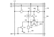
本発明の画素の基本構成について、図1を用いて説明する。図1に示す画素は、トランジスタ110、第1のスイッチ111、第2のスイッチ112、第3のスイッチ113、第4のスイッチ114、容量素子115、発光素子116を有する。なお、画素は、信号線117、第1の走査線118、第2の走査線119、第3の走査線120、第4の走査線121、第1の電位供給線122、第2の電位供給線123及び電源線124に接続されている。本実施の形態において、トランジスタ110はNチャネル型トランジスタとし、そのゲート・ソース間電圧(Vgs)がしきい値電圧(Vth)を上回ったとき、導通状態になるものとする。また、発光素子116の画素電極は陽極、対向電極125は陰極とする。なお、トランジスタのゲート・ソース間電圧はVgs、ドレイン・ソース間電圧はVds、しきい値電圧はVth、容量素子に蓄積された電圧はVcsと記し、電源線124、第1の電位供給線122、第2の電位供給線123及び信号線117を、それぞれ第1の配線、第2の配線、第3の配線、第4の配線とも呼ぶ。
(Embodiment 1)
The basic configuration of the pixel of the present invention will be described with reference to FIG. The pixel illustrated in FIG. 1 includes a
トランジスタ110の第1の電極(ソース電極及びドレイン電極の一方)は、発光素子116の画素電極に接続され、第2の電極(ソース電極及びドレイン電極の他方)は電源線124に接続され、ゲート電極は第4のスイッチ114及び第2のスイッチ112を介して第1の電位供給線122と接続されている。なお、第4のスイッチ114は、トランジスタ110のゲート電極と第2のスイッチ112の間に接続されている。また、第4のスイッチ114と第2のスイッチ112との接続箇所をノード130とすると、ノード130は第1のスイッチ111を介して信号線117と接続されている。また、トランジスタ110の第1の電極は第3のスイッチ113を介して第2の電位供給線123とも接続されている。
The first electrode (one of the source electrode and the drain electrode) of the
さらに、ノード130とトランジスタ110の第1の電極との間に容量素子115が接続されている。つまり、容量素子115の第1の電極が第4のスイッチ114を介しトランジスタ110のゲート電極に、第2の電極がトランジスタ110の第1の電極に接続されている。容量素子115は、配線、半導体層や電極によって絶縁膜を挟むことで形成しても良いし、場合によってはトランジスタ110のゲート容量を用いて省略することもできる。これらの電圧を保持する手段を保持容量と言う。なお、ノード130と、第1のスイッチ111と容量素子115の第1の電極とが接続されている配線との接続箇所をノード131とし、トランジスタ110の第1の電極と、容量素子115の第2の電極と発光素子116の画素電極とが接続されている配線との接続箇所をノード132とする。
Further, the
なお、第1の走査線118、第2の走査線119、第3の走査線120、第4の走査線121に信号を入力することにより、それぞれ第1のスイッチ111、第2のスイッチ112、第3のスイッチ113、第4のスイッチ114のオンオフが制御される。
Note that by inputting signals to the
信号線117には、ビデオ信号に相当する画素の階調に従った信号、即ち輝度データに応じた電位が入力される。
A signal in accordance with the gradation of a pixel corresponding to a video signal, that is, a potential corresponding to luminance data is input to the
次に、図1で示した画素の動作について図2のタイミングチャート及び図3を用いて説明する。なお、図2において1画面分の画像を表示する期間に相当する1フレーム期間は、初期化期間、しきい値書き込み期間、データ書き込み期間及び発光期間に分割される。また、初期化期間、しきい値書き込み期間、データ書き込み期間をまとめてアドレス期間と呼ぶ。1フレーム期間は特に限定はないが、画像をみる人がちらつき(フリッカ)を感じないように少なくとも1/60秒以下とすることが好ましい。 Next, the operation of the pixel shown in FIG. 1 will be described with reference to the timing chart of FIG. 2 and FIG. In FIG. 2, one frame period corresponding to a period for displaying an image for one screen is divided into an initialization period, a threshold writing period, a data writing period, and a light emission period. The initialization period, threshold write period, and data write period are collectively referred to as an address period. There is no particular limitation on the period of one frame, but it is preferable to set it to at least 1/60 second or less so that a person viewing the image does not feel flicker.
なお、発光素子116の対向電極125及び第1の電位供給線122にはV1の電位が、第2の電位供給線123にはV1−Vth−α(α:任意の正の数)の電位が入力される。また、電源線124には、V2の電位が入力される。
Note that the potential of V1 is applied to the
ここでは動作を説明するために、発光素子116の対向電極125の電位は、第1の電位供給線122の電位と同じであるとしたが、発光素子116が発光するために少なくとも必要とする電位差をVELとすると、対向電極125の電位はV1−Vth−α―VELの電位より高い値であれば良い。また、電源線124の電位V2は、対向電極125の電位に発光素子116が発光するために少なくとも必要とする電位差(VEL)を加算した値より大きい値であれば良いが、説明上ここでは対向電極125の電位をV1としたため、V2はV1+VELより大きい値であれば良い。
Here, in order to explain the operation, the potential of the
まず、図2(A)及び図3(A)に示すように初期化期間では、第1のスイッチ111をオフとし、第2のスイッチ112、第3のスイッチ113及び第4のスイッチ114をオンとする。このとき、トランジスタ110の第1の電極はソース電極となり、その電位は第2の電位供給線123と等しくなるためV1−Vth−αとなる。一方、ゲート電極の電位はV1となる。よって、トランジスタ110のゲート・ソース間電圧VgsはVth+αとなり、トランジスタ110は導通状態となる。そして、トランジスタ110のゲート電極と第1の電極との間に設けられた容量素子115にVth+αが保持される。なお、第4のスイッチ114はオンとした場合について説明したが、オフとしても良い。
First, as shown in FIGS. 2A and 3A, in the initialization period, the
次に、図2(B)及び図3(B)に示すしきい値書き込み期間では、第3のスイッチ113をオフとする。そのため、トランジスタ110の第1の電極即ちソース電極の電位は次第に上昇しV1−Vthとなったところ、つまりトランジスタ110のゲート・ソース間電圧Vgsがしきい値電圧(Vth)となったところで、トランジスタ110は非導通状態となる。よって、容量素子115に保持される電圧はVthとなる。
Next, in the threshold writing period illustrated in FIGS. 2B and 3B, the
その後の図2(C)及び図3(C)に示すデータ書き込み期間においては、第2のスイッチ112及び第4のスイッチ114をオフとした後、第1のスイッチ111をオンとし、信号線117より輝度データに応じた電位(V1+Vdata)を入力する。なお、第4のスイッチ114をオフにすることにより、トランジスタ110を非導通状態に保つことができる。そのため、データ書き込み時の電源線124から供給される電流による、容量素子115の第2の電極の電位の変動を抑制することができる。よって、このとき容量素子115に保持される電圧Vcsは、容量素子115及び発光素子116の静電容量をそれぞれC1、C2とすると式(1)のように表すことができる。
![]()
![]()
ただし、発光素子116は容量素子115に比べ膜厚が薄いうえ電極面積が大きいため、C2>>C1となる。よって、C2/(C1+C2)≒1より容量素子115に保持される電圧Vcsは式(2)となる。なお、次の発光期間において発光素子116を非発光としたい場合には、Vdata≦0の電位を入力する。
![]()
![]()
次に、図2(D)及び図3(D)に示す発光期間では、第1のスイッチ111をオフとし、第4のスイッチ114をオンとする。このとき、トランジスタ110のゲート・ソース間電圧はVgs=Vth+Vdataとなり、トランジスタ110が導通状態になる。よって、輝度データに応じた電流がトランジスタ110及び発光素子116に流れ、発光素子116が発光する。
Next, in the light emission period illustrated in FIGS. 2D and 3D, the
なお、発光素子に流れる電流Iは、トランジスタ110を飽和領域で動作させた場合、式(3)で表される。

また、トランジスタ110を線形領域で動作させた場合、発光素子に流れる電流Iは式(4)で表される。
ここで、Wはトランジスタ110のチャネル幅、Lはチャネル長、μは移動度、Coxは蓄積容量を指す。
Here, W is the channel width of the
式(3)及び式(4)より、トランジスタ110の動作領域が飽和領域、線形領域のいずれの場合においても、発光素子116に流れる電流は、トランジスタ110のしきい値電圧(Vth)に依存しない。よって、トランジスタ110のしきい値電圧のばらつきに起因した電流値のばらつきを抑制し、輝度データに対応した電流値を発光素子116に供給することができる。
From the equations (3) and (4), the current flowing through the light-emitting
以上のことから、トランジスタ110のしきい値電圧のばらつきに起因した輝度のばらつきを抑制することができる。また、対向電極の電位を一定として動作させるため消費電力を低くすることが可能である。
From the above, variation in luminance due to variation in threshold voltage of the
さらに、トランジスタ110を飽和領域で動作させた場合においては、発光素子116の劣化による輝度のばらつきも抑制できる。発光素子116が劣化すると、発光素子116のVELは増大し、トランジスタ110の第1の電極、即ちソース電極の電位は上昇する。このとき、トランジスタ110のソース電極は容量素子115の第2の電極に、トランジスタ110のゲート電極は容量素子115の第1の電極に接続されており、なおかつゲート電極側は浮遊状態となっている。そのため、ソース電位の上昇に伴い、同じ電位だけトランジスタ110のゲート電位も上昇する。よって、トランジスタ110のVgsは変化しないため、たとえ発光素子が劣化してもトランジスタ110及び発光素子116に流れる電流に影響しない。なお、式(3)においても発光素子に流れる電流Iはソース電位やドレイン電位に依存しないことがわかる。
Further, when the
よって、トランジスタ110を飽和領域で動作させた場合においては、トランジスタ110のしきい値電圧のばらつき及び発光素子116の劣化に起因したトランジスタ110に流れる電流のばらつきを抑制することができる。
Thus, when the
なお、トランジスタ110を飽和領域で動作させた場合、チャネル長Lが短いほど、降伏現象によりドレイン電圧を著しく増大させると電流が大量に流れやすい。
Note that when the
また、ドレイン電圧をピンチオフ電圧より増大させるとピンチオフ点がソース側に移動し、実質チャネルとして機能する実効的なチャネル長は減少する。これにより、電流値が増大する。この現象をチャネル長変調と呼ぶ。なお、ピンチオフ点とはチャネルが消滅していきゲート下においてチャネルの厚さが0となる境界箇所であり、ピンチオフ電圧とはピンチオフ点がドレイン端となる時の電圧を指す。この現象も、チャネル長Lが短いほど起こり易い。例えば、チャネル長変調による電圧−電流特性のモデル図を図4に示す。なお、図4において、トランジスタのチャネル長Lは(a)>(b)>(c)である。 When the drain voltage is increased above the pinch-off voltage, the pinch-off point moves to the source side, and the effective channel length that functions as a substantial channel decreases. As a result, the current value increases. This phenomenon is called channel length modulation. Note that the pinch-off point is a boundary where the channel disappears and the channel thickness becomes 0 under the gate, and the pinch-off voltage indicates a voltage when the pinch-off point becomes the drain end. This phenomenon is more likely to occur as the channel length L is shorter. For example, a model diagram of voltage-current characteristics by channel length modulation is shown in FIG. In FIG. 4, the channel length L of the transistor is (a)> (b)> (c).
以上のことから、トランジスタ110を飽和領域で動作させる場合、ドレイン・ソース間電圧Vdsに対する電流Iはより一定に近い方が好ましい。よって、トランジスタ110のチャネル長Lは長い方がより好ましい。たとえば、トランジスタのチャネル長Lはチャネル幅Wより大きい方が好ましい。また、チャネル長Lは10μm以上50μm以下、より望ましくは15μm以上40μm以下が好ましい。しかし、チャネル長L及びチャネル幅Wはこれに限定されない。
From the above, when the
また、初期化期間において発光素子116に逆方向のバイアス電圧を印加しているため、発光素子における短絡箇所を絶縁化したり、発光素子の劣化を抑制することができる。よって、発光素子の寿命を延ばすことができる。
In addition, since a reverse bias voltage is applied to the light-emitting
なお、トランジスタのしきい値電圧のばらつきに起因する電流値のばらつきを抑制することができるため、そのトランジスタによって制御された電流の供給先は特に限定されない。そのため、図1に示した発光素子116は、EL素子(有機EL素子、無機EL素子又は有機物及び無機物を含むEL素子)、電子放出素子、液晶素子、電子インクなどを適用することができる。
Note that since variation in current value due to variation in threshold voltage of a transistor can be suppressed, a supply destination of current controlled by the transistor is not particularly limited. Therefore, an EL element (an organic EL element, an inorganic EL element, or an EL element containing an organic substance and an inorganic substance), an electron-emitting element, a liquid crystal element, electronic ink, or the like can be used as the light-emitting
また、トランジスタ110は発光素子116に供給する電流値を制御する機能を有していれば良く、トランジスタの種類は特に限定されない。そのため、結晶性半導体膜を用いた薄膜トランジスタ(TFT)、非晶質シリコンや多結晶シリコンに代表される非単結晶半導体膜を用いた薄膜トランジスタ、半導体基板やSOI基板を用いて形成されるトランジスタ、MOS型トランジスタ、接合型トランジスタ、バイポーラトランジスタ、有機半導体やカーボンナノチューブを用いたトランジスタ、その他のトランジスタを適用することができる。
The
第1のスイッチ111は画素の階調に従った信号を容量素子に入力するタイミングを選択し、トランジスタ110のゲート電極に供給する信号を制御するものであり、第2のスイッチ112はトランジスタ110のゲート電極に所定の電位を与えるタイミングを選択し、トランジスタ110のゲート電極に所定の電位を供給するか否かを制御するものであり、第3のスイッチ113は容量素子115に書き込まれた電位を初期化するための所定の電位を与えるタイミングを選択したり、トランジスタ110の第1の電極の電位を低くするものである。なお、第4のスイッチ114はトランジスタ110のゲート電極と容量素子115とを接続するか否かを制御するものである。そのため、第1のスイッチ111、第2のスイッチ112、第3のスイッチ113、第4のスイッチ114は、上記機能を有していれば特に限定されない。たとえば、トランジスタやダイオードでもよいし、それらを組み合わせた論理回路でもよい。なお、第1乃至第3のスイッチは、上記のタイミングで信号もしくは電位を画素に与えることができれば特に必要はない。また、第4のスイッチを設けなくてもよい場合については実施の形態2に示す。
The
次に、図5に第1のスイッチ111、第2のスイッチ112、第3のスイッチ113、第4のスイッチ114にNチャネル型のトランジスタを適用した場合について示す。なお、図1の構成と共通するところは共通の符号を用いてその説明を省略する。
Next, FIG. 5 illustrates the case where N-channel transistors are used for the
第1のスイッチングトランジスタ511が第1のスイッチ111に相当し、第2のスイッチングトランジスタ512が第2のスイッチ112に相当し、第3のスイッチングトランジスタ513が第3のスイッチ113に相当し、第4のスイッチングトランジスタ514が第4のスイッチ114に相当する。なお、トランジスタ110のチャネル長は、第1のスイッチングトランジスタ511、第2のスイッチングトランジスタ512、第3のスイッチングトランジスタ513及び第4のスイッチングトランジスタ514のいずれのトランジスタのチャネル長より長い方が好ましい。
The
第1のスイッチングトランジスタ511はゲート電極が第1の走査線118に接続され、第1の電極が信号線117に接続され、第2の電極がノード131に接続されている。
The
また、第2のスイッチングトランジスタ512はゲート電極が第2の走査線119に接続され、第1の電極が第1の電位供給線122に接続され、第2の電極がノード130に接続されている。
The
第3のスイッチングトランジスタ513はゲート電極が第3の走査線120に接続され、第1の電極がノード132に接続され、第2の電極が第2の電位供給線123に接続されている。
The
また、第4のスイッチングトランジスタ514はゲート電極が第4の走査線121に接続され、第1の電極がトランジスタ110のゲート電極に接続され、第2の電極がノード130に接続されている。
The
各々のスイッチングトランジスタは、それぞれの走査線に入力される信号がHレベルのときにオンとなり、入力される信号がLレベルのときにオフとなる。 Each switching transistor is turned on when the signal input to each scanning line is at the H level, and is turned off when the input signal is at the L level.
図5の画素構成においても、図1と同様の動作方法によりトランジスタ110のしきい値電圧のばらつきに起因した電流値のばらつきを抑制することができる。よって、輝度データに対応した電流を発光素子116に供給することができ、輝度のばらつきを抑制することが可能となる。また、トランジスタ110を飽和領域で動作させた場合においては、発光素子116の劣化に起因した輝度のばらつきも抑制することができる。
Also in the pixel configuration in FIG. 5, variation in current value due to variation in threshold voltage of the
また、Nチャネル型のトランジスタのみで画素を構成することができるため、製造工程の簡略化を図ることができる。また、画素を構成するトランジスタの半導体層にアモルファス半導体やセミアモルファス半導体(若しくは微結晶半導体ともいう)などの非晶質半導体を用いることができる。例えば、アモルファス半導体としてアモルファスシリコン(a−Si:H)が挙げられる。これら非晶質半導体を用いることにより、さらに製造工程の簡略化が可能である。したがって、製造コストの削減や歩留まりの向上を図ることができる。 In addition, since a pixel can be formed using only N-channel transistors, the manufacturing process can be simplified. In addition, an amorphous semiconductor such as an amorphous semiconductor or a semi-amorphous semiconductor (or a microcrystalline semiconductor) can be used for a semiconductor layer of a transistor included in the pixel. For example, amorphous silicon (a-Si: H) can be given as an amorphous semiconductor. By using these amorphous semiconductors, the manufacturing process can be further simplified. Therefore, the manufacturing cost can be reduced and the yield can be improved.
なお、第1のスイッチングトランジスタ511、第2のスイッチングトランジスタ512、第3のスイッチングトランジスタ513及び第4のスイッチングトランジスタ514は、単なるスイッチとして動作させるため、トランジスタの極性(導電型)は特に限定されない。ただし、オフ電流が少ないトランジスタを用いることが望ましい。オフ電流が少ないトランジスタとしては、LDD領域を設けているものやマルチゲート構造にしているものなどがある。また、Nチャネル型とPチャネル型の両方を用いて、CMOS型のスイッチにしてもよい。
Note that the
また、図1に示した第4のスイッチ114は、ノード130とノード131の間に接続しても良い。このような構成を図6に示す。なお、図1における第4のスイッチ114は、第4のスイッチ614に相当し、図1の構成と共通するところは共通の符号を用いてその説明を省略する。
Further, the
図6の画素構成においても、図1と同様の動作方法によりトランジスタ110のしきい値電圧のばらつきに起因した電流値のばらつきを抑制することができる。よって、輝度データに対応した電流を発光素子116に供給することができ、輝度のばらつきを抑制することが可能となる。また、トランジスタ110を飽和領域で動作させた場合においては、発光素子116の劣化に起因した輝度のばらつきも抑制することができる。
Also in the pixel configuration in FIG. 6, variation in current value due to variation in threshold voltage of the
また、図1に示した第4のスイッチ114は、ノード132からトランジスタ110の第2の電極と電源線124との接続箇所までの経路に設けても良い。
Further, the
このような構成の一つを図7に示す。図7の構成において、図1における第4のスイッチ114は第4のスイッチ714に相当し、トランジスタ110の第2の電極と電源線124との間に接続されている。なお、図1の構成と共通するところは共通の符号を用いてその説明を省略する。
One such configuration is shown in FIG. 7, the
第4のスイッチ714により、データ書き込み時においてトランジスタ110が導通状態となった場合においても、第4のスイッチ714をオフにすることによりトランジスタ110への電流を遮断することができる。よって、データ書き込み期間における容量素子115の第2の電極の電位の変動を抑制することができる。
With the
したがって、図7の画素構成においても、図1と同様の動作方法によりトランジスタ110のしきい値電圧のばらつきに起因した電流値のばらつきを抑制することができる。よって、輝度データに対応した電流を発光素子116に供給することができ、輝度のばらつきを抑制することが可能となる。また、トランジスタ110を飽和領域で動作させた場合においては、発光素子116の劣化に起因した輝度のばらつきも抑制することができる。また、初期化期間において、第4のスイッチ714をオフさせた場合には消費電力の低減が可能である。
Therefore, also in the pixel configuration in FIG. 7, variation in current value due to variation in threshold voltage of the
また、他の構成の一つを図8に示す。図8の構成において、図1における第4のスイッチ114は第4のスイッチ814に相当し、トランジスタ110の第1の電極とノード132との間に接続されている。なお、図1の構成と共通するところは共通の符号を用いてその説明を省略する。
Another configuration is shown in FIG. 8, the
第4のスイッチ814により、データ書き込み時においてトランジスタ110が導通状態となった場合においても、第4のスイッチ814をオフにすることによりノード132に流れる電流を遮断することができる。よって、データ書き込み期間における容量素子115の第2の電極の電位の変動を抑制することができる。
With the
したがって、図8の画素構成においても、図1と同様の動作方法によりトランジスタ110のしきい値電圧のばらつきに起因した電流値のばらつきを抑制することができる。よって、輝度データに対応した電流を発光素子116に供給することができ、輝度のばらつきを抑制することが可能となる。また、トランジスタ110を飽和領域で動作させた場合においては、発光素子116の劣化に起因した輝度のばらつきも抑制することができる。また、初期化期間において、第4のスイッチ814をオフさせた場合には消費電力の低減が可能である。
Therefore, also in the pixel configuration of FIG. 8, variation in current value due to variation in threshold voltage of the
なお、第4のスイッチ614、第4のスイッチ714及び第4のスイッチ814においても、第1乃至第3のスイッチと同様、トランジスタやダイオードでもよいし、それらを組み合わせた論理回路でもよい。
Note that the
また、図7及び8で示したように第4のスイッチをノード132からトランジスタ110の第2の電極と電源線124との接続箇所までの経路に設けた場合、発光期間において第4のスイッチ114をオフすることにより強制的に非発光状態を作ることも可能である。このような動作によって、発光期間を自由に設定できる。また、黒表示を挿入することで、残像を見えにくくし、動画特性の向上を図ることも可能である。
7 and 8, in the case where the fourth switch is provided in the path from the
続いて、上述した本発明の画素を有する表示装置について図9を用いて説明する。 Next, a display device having the above-described pixel of the present invention will be described with reference to FIG.
表示装置は、信号線駆動回路911、走査線駆動回路912及び画素部913を有し、画素部913には、信号線駆動回路911から列方向に伸張して配置された複数の信号線S1〜Sm、第1の電位供給線P1_1〜Pm_1、電源線P1_3〜Pm_3と、走査線駆動回路912から行方向に伸張して配置された複数の第1の走査線G1_1〜Gn_1、第2の走査線G1_2〜Gn_2、第3の走査線G1_3〜Gn_3及び第4の走査線G1_4〜Gn_4と、信号線S1〜Smに対応してマトリクスに配置された複数の画素914とを有する。また、第1の走査線G1_1〜Gn_1と平行に複数の第2の電位供給線P1_2〜Pn_2を有している。そして、各画素914は、信号線Sj(信号線S1〜Smのうちいずれか一)、第1の電位供給線Pj_1、電源線Pj_3、第1の走査線Gi_1(走査線G1_1〜Gn_1のうちいずれか一)、第2の走査線Gi_2、第3の走査線Gi_3、第4の走査線Gi_4、第2の電位供給線Pi_2と接続されている。
The display device includes a signal
なお、信号線Sj、第1の電位供給線Pj_1、電源線Pj_3、第1の走査線Gi_1、第2の走査線Gi_2、第3の走査線Gi_3、第4の走査線Gi_4、第2の電位供給線Pi_2は、それぞれ図1の信号線117、第1の電位供給線122、電源線124、第1の走査線118、第2の走査線119、第3の走査線120、第4の走査線121、第2の電位供給線123に相当する。
Note that the signal line Sj, the first potential supply line Pj_1, the power supply line Pj_3, the first scanning line Gi_1, the second scanning line Gi_2, the third scanning line Gi_3, the fourth scanning line Gi_4, and the second potential. The supply line Pi_2 includes the
走査線駆動回路912から出力される信号により、動作させる画素の行を選択すると共に同行に属するそれぞれの画素に対し同時に図2に示した動作を行う。なお、図2のデータ書き込み期間においては、選択された行の画素に信号線駆動回路911から出力されたビデオ信号を書き込む。このとき、それぞれの画素に輝度データに応じた電位が各信号線S1〜Smに入力される。
A row of pixels to be operated is selected by a signal output from the scan
図10に示すように、例えばi行目のデータ書き込み期間を終えるとi+1行目に属する画素へ信号の書き込みを行う。なお、図10には、各行におけるデータ書き込み期間を表すためにこれを忠実に表すことができる図2の第1のスイッチ111の動作のみを抜き出して記載している。そして、i行目においてデータ書き込み期間を終えた画素は、発光期間に移り、その画素へ書き込まれた信号にしたがって発光する。
As shown in FIG. 10, for example, when the data writing period of the i-th row ends, a signal is written to the pixel belonging to the i + 1-th row. FIG. 10 shows only the operation of the
よって、各行におけるデータ書き込み期間さえ重複しなければ、各行自由に初期化開始時期を設定することができる。また、各画素は自身のアドレス期間を除き発光することが可能であるため、1フレーム期間における発光期間の割合(即ち、デューティー比)を非常に大きくでき、おおむね100%にすることも可能となる。よって、輝度のばらつきが少なくデューティー比が高い表示装置を得ることができる。 Therefore, if even the data writing period in each row does not overlap, the initialization start time can be set freely for each row. In addition, since each pixel can emit light except its own address period, the ratio of the light emission period in one frame period (that is, the duty ratio) can be very large, and can be almost 100%. . Therefore, a display device with a small luminance variation and a high duty ratio can be obtained.
また、しきい値書き込み期間を長く設定することも可能であるため、トランジスタのしきい値電圧をより正確に容量素子に書き込むことができる。よって、表示装置としての信頼性が向上させることができる。 Further, since the threshold writing period can be set long, the threshold voltage of the transistor can be written to the capacitor more accurately. Thus, reliability as a display device can be improved.
なお、図9に示した表示装置の構成は一例であって本発明はこれに限定されない。例えば、第1の電位供給線P1_1〜Pm_1は信号線S1〜Smと平行に配置されている必要はなく、第1の走査線G1_1〜Gn_1に平行に配置されていても良い。 Note that the configuration of the display device illustrated in FIG. 9 is an example, and the present invention is not limited to this. For example, the first potential supply lines P1_1 to Pm_1 do not need to be arranged in parallel with the signal lines S1 to Sm, and may be arranged in parallel to the first scanning lines G1_1 to Gn_1.
ところで、表示装置の階調を表現する駆動方式には、アナログ階調方式とデジタル階調方式がある。アナログ階調方式には、発光素子の発光強度をアナログ制御する方式と発光素子の発光時間をアナログ制御する方式がある。アナログ階調方式においては発光素子の発光強度をアナログ制御する方式がよく用いられている。一方、デジタル階調方式はデジタル制御で発光素子をオンオフさせ、階調を表現している。デジタル階調方式の場合、デジタル信号で処理できるためノイズに強いというメリットがあるが、発光・非発光の2状態しかないため、このままでは2階調しか表現できない。そこで、別の手法を組み合わせて、多階調化を図ることが行われている。多階調化のための手法としては、画素の発光面積に重みをつけてその選択により階調表示を行う面積階調方式と、発光時間に重みをつけてその選択により階調表示を行う時間階調方式とがある。 Incidentally, there are an analog gray scale method and a digital gray scale method as drive methods for expressing the gray scale of the display device. The analog gradation method includes a method of analog control of the light emission intensity of the light emitting element and a method of analog control of the light emission time of the light emitting element. In the analog gradation method, a method of analog control of the light emission intensity of the light emitting element is often used. On the other hand, in the digital gradation method, gradation is expressed by turning on and off the light emitting element by digital control. In the digital gradation method, since it can be processed with a digital signal, there is a merit of being resistant to noise. However, since there are only two states of light emission and non-light emission, only two gradations can be expressed as it is. In view of this, multi-gradation is being achieved by combining different methods. As a method for multi-gradation, there are an area gradation method in which gradation display is performed by weighting the light emitting area of the pixel and selection is performed, and a time in which gradation display is performed by weighting the light emission time and selected. There is a gradation method.
このデジタル階調方式と時間階調方式とを組み合わせた場合、図49に示すように、1フレーム期間を複数のサブフレーム期間(SFn)に分割する。各サブフレーム期間は、初期化期間、しきい値書き込み期間及びデータ書き込み期間を有するアドレス期間(Ta)と、発光期間(Ts)とを有する。なお、サブフレーム期間は表示ビット数nに応じた数を1フレーム期間に設ける。また、各サブフレーム期間における発光期間の長さの比を2(n−1):2(n−2):・・・:2:1とし、各発光期間で発光素子の発光、もしくは非発光を選択し、発光素子が発光している1フレーム期間中の合計時間の差を利用して階調表現を行う。1フレーム期間において、発光している合計時間が長ければ輝度が高く、短ければ輝度が低くなる。なお、図49においては4ビット階調の例を示しており、1フレーム期間は4つのサブフレーム期間に分割され、発光期間の組み合わせによって、24=16階調を表現できる。なお、発光期間の長さの比は、特に2のべき乗の比としなくても、階調表現は可能である。また、あるサブフレーム期間をさらに分割していても良い。 When the digital gradation method and the time gradation method are combined, one frame period is divided into a plurality of subframe periods (SFn) as shown in FIG. Each subframe period includes an address period (Ta) having an initialization period, a threshold value writing period and a data writing period, and a light emission period (Ts). Note that a number corresponding to the number n of display bits is provided in one frame period in the subframe period. In addition, the ratio of the lengths of the light emitting periods in each subframe period is set to 2 (n-1) : 2 (n-2) :...: 2: 1, and the light emitting element emits light or does not emit light in each light emitting period. Is selected, and gradation expression is performed using a difference in total time during one frame period in which the light emitting element emits light. In one frame period, the luminance is high if the total emission time is long, and the luminance is low if it is short. Note that FIG. 49 shows an example of 4-bit gradation, and one frame period is divided into four subframe periods, and 2 4 = 16 gradations can be expressed by a combination of light emission periods. Note that gradation expression is possible even if the ratio of the lengths of the light emission periods is not particularly a power-of-two ratio. Further, a certain subframe period may be further divided.
なお、上記のように時間階調方式を用いて多階調化を図る場合、下位ビットの発光期間の長さは短いため、発光期間の終了後直ちに次のサブフレーム期間のデータ書き込み動作を開始しようとすると、前のサブフレーム期間のデータ書き込み動作と重複してしまい、正常な動作ができなくなる。そのため、図7及び図8で示したように第4のスイッチをノード132からトランジスタ110の第2の電極と電源線124との接続箇所までの間に設け、発光期間において第4のスイッチをオフし強制的に非発光状態を作ることで、全行に要するデータ書き込み期間より短い発光も表現することができる。よって、アナログ階調において特に有効であることはもちろん、上記のようなデジタル階調方式と時間階調方式とを組み合わせた方式においても有効である。
Note that when multi-gradation is performed using the time gray scale method as described above, since the light emission period of the lower bits is short, the data writing operation for the next subframe period starts immediately after the light emission period ends. Attempting to do so overlaps the data write operation in the previous subframe period, and normal operation cannot be performed. Therefore, as shown in FIGS. 7 and 8, a fourth switch is provided between the
なお、しきい値電圧のばらつきには、画素間における各トランジスタのしきい値電圧の違いのほか、1つのトランジスタに注目した場合において経時的なしきい値電圧の変化も含むものとする。さらに、各トランジスタのしきい値電圧の違いは、トランジスタの作製時におけるトランジスタ特性の違いによるものも含まれるものとする。なお、ここでいうトランジスタは発光素子等の負荷に電流を供給する機能を有するトランジスタを指す。 Note that the variation in threshold voltage includes a change in threshold voltage over time when attention is paid to one transistor in addition to a difference in threshold voltage of each transistor between pixels. Further, the difference in threshold voltage of each transistor includes a difference in transistor characteristics at the time of manufacturing the transistor. Note that the transistor here refers to a transistor having a function of supplying current to a load such as a light emitting element.
(実施の形態2)
本実施形態では、実施の形態1とは異なる構成の画素を図11に示す。なお、実施の形態1と同様のものに関しては共通の符号を用いて示し、同一部分又は同様な機能を有する部分の詳細な説明は省略する。
(Embodiment 2)
In this embodiment mode, a pixel having a different structure from that in
図11に示す画素は、トランジスタ110、第1のスイッチ111、第2のスイッチ112、第3のスイッチ113、容量素子115、発光素子116を有する。なお、画素は、信号線117、第1の走査線118、第2の走査線119、第3の走査線120、第1の電位供給線122、第2の電位供給線123及び電源線124に接続されている。
A pixel illustrated in FIG. 11 includes a
トランジスタ110の第1の電極(ソース電極及びドレイン電極の一方)は、発光素子116の画素電極に接続され、第2の電極(ソース電極及びドレイン電極の他方)は電源線124に接続され、ゲート電極は第2のスイッチ112を介して第1の電位供給線122と接続されている。また、トランジスタ110のゲート電極は、第1のスイッチ111を介して信号線117とも接続されており、第1の電極は第3のスイッチ113を介して第2の電位供給線123とも接続されている。
The first electrode (one of the source electrode and the drain electrode) of the
さらに、トランジスタ110のゲート電極と第1の電極との間に容量素子115が接続されている。つまり、容量素子115の第1の電極がトランジスタ110のゲート電極に、容量素子115の第2の電極がトランジスタ110の第1の電極に接続されている。容量素子115は、配線、半導体層や電極によって絶縁膜を挟むことで形成しても良いし、トランジスタ110のゲート容量を用いて省略することもできる。
Further, the
つまり、図11に示す画素は、図1に示す画素が有する第4のスイッチ114が設けられていない構成である。図11に示す画素においても、図2のタイミングチャートに従い、動作させる。
That is, the pixel illustrated in FIG. 11 has a structure in which the
図1の画素とは異なり、図2(C)のデータ書き込み期間において、信号線117より輝度データに応じた電位(V1+Vdata)を入力する際、トランジスタ110が導通状態となり、容量素子115の第2の電極の電位が上昇してしまう。よって、容量素子115に保持される電圧VcsはVth+Vdataより小さくなってしまう。このような場合には、容量素子115の第2の電極の電位の変動を加味した電位(V1+V´data)を信号線117より入力すれば良い。
Unlike the pixel in FIG. 1, when a potential (V1 + Vdata) corresponding to luminance data is input from the
ただし、容量素子115と発光素子116との静電容量の違いによっては、必ずしも信号線より入力する電位をV1+V´datatする必要はなく、容量素子115の第2の電極の電位の変動が容量素子115に保持されるべき電圧にさほど影響を及ぼさない程度であれば、実施の形態1と同様、信号線より入力する電位をV1+Vdataとしても良い。
However, depending on the difference in capacitance between the
実施の形態1に示したように、第1のスイッチ111は画素の階調に従った信号を容量素子に入力するタイミングを選択し、トランジスタ110のゲート電極に供給する信号を制御するものであり、第2のスイッチ112はトランジスタ110のゲート電極に所定の電位を与えるタイミングを選択し、トランジスタ110のゲート電極に所定の電位を供給するか否かを制御するものであり、第3のスイッチ113は容量素子115に書き込まれた電位を初期化するための所定の電位を与えるタイミングを選択したり、トランジスタ110の第1の電極の電位を低くするものである。そのため、第1のスイッチ111、第2のスイッチ112、第3のスイッチ113は、上記機能を有していれば特に限定されない。たとえば、トランジスタやダイオードでもよいし、それらを組み合わせた論理回路でもよい。なお、第1乃至第3のスイッチは、上記のタイミングで信号もしくは電位を画素に与えることができれば特に必要はない。例えば、画素の階調に従った信号をトランジスタ110のゲート電極に入力することができる場合には、図42に示すように第1のスイッチ111を設けなくても良い。図42に示す画素は、トランジスタ110、第2のスイッチ112、第3のスイッチ113、画素電極4240を有する。そして、トランジスタ110の第1の電極(ソース電極及びドレイン電極の一方)は画素電極4240と第3のスイッチ113とに接続され、ゲート電極は第2のスイッチ112を介して第1の電位供給線122に接続されている。なお、トランジスタ110のゲート容量4215を保持容量として利用しているため、図11における容量素子115を特に設ける必要なない。このような画素においても、図11と同様に各スイッチを動作させ、それぞれの電極に所望の電位を供給することで、トランジスタ110のしきい値電圧のばらつきに起因した電流値のばらつきを抑制することができる。よって、画素電極4240に所望の電流を供給することができる。
As shown in
また、第1の電位供給線122は、第1の走査線118等と平行に設けられていても良い。このような場合の図11の上面図の一形態を図43に示す。なお、図43において、各スイッチは、スイッチングトランジスタとして記載した。図11における第1のスイッチ111、第2のスイッチ112、第3のスイッチ113は、それぞれ第1のスイッチングトランジスタ4301、第2のスイッチングトランジスタ4302、第3のスイッチングトランジスタ4303に相当とする。
Further, the first
導電層4310は、第1の走査線118と第1のスイッチングトランジスタ4301のゲート電極として機能する部分を含み、導電層4311は信号線117と第1のスイッチングトランジスタ4301の第1の電極として機能する部分とを含む。また、導電層4312は第1のスイッチングトランジスタ4301の第2の電極として機能する部分と、容量素子115の第1の電極として機能する部分と、第2のスイッチングトランジスタ4302の第1の電極として機能する部分とを含む。導電層4313は第2のスイッチングトランジスタ4302のゲート電極として機能する部分を含み、配線4314を介して第2の走査線119と接続されている。導電層4315は、第1の電位供給線122と第2のスイッチングトランジスタ4302の第2の電極として機能する部分とを含む。導電層4316はトランジスタ110のゲート電極として機能する部分を含み、配線4317を介して導電層4312と接続されている。導電層4318は電源線124とトランジスタ110の第2の電極として機能する部分とを含む。導電層4319は、トランジスタ110の第1の電極として機能する部分を含み、発光素子の画素電極4344と接続されている。また、導電層4320は第3のスイッチングトランジスタ4303の第1の電極として機能する部分を含み、画素電極4344と接続されている。導電層4321は、第3のスイッチングトランジスタ4303の第2の電極として機能する部分を含み、第2の電位供給線123と接続されている。また、導電層4322は、第3の走査線120と第3のスイッチングトランジスタ4303のゲート電極として機能する部分を含む。
The
なお、各々の導電層のうち第1のスイッチングトランジスタ4301のゲート電極、第1の電極及び第2の電極として機能する部分は半導体層4333と重なって形成されている部分であり、第2のスイッチングトランジスタ4302のゲート電極、第1の電極及び第2の電極として機能する部分は半導体層4334と重なって形成されている部分であり、第3のスイッチングトランジスタ4303のゲート電極、第1の電極及び第2の電極として機能する部分は半導体層4335と重なって形成されている部分である。また、トランジスタ110のゲート電極、第1の電極及び第2の電極として機能する部分は半導体層4336と重なって形成されている導電層部分である。容量素子115は、導電層4312と画素電極4344が重なっている部分に形成されている。
Note that portions of the conductive layers that function as the gate electrode, the first electrode, and the second electrode of the
導電層4310、導電層4313、導電層4316、導電層4322、第2の走査線119及び第2の電位供給線123は、同一材料で同じ層で作製することができる。また、半導体層4333、半導体層4334、半導体層4335及び半導体層4336や、導電層4311、導電層4312、導電層4315、導電層4318、導電層4319、導電層4320及び導電層4321はそれぞれ同一材料で同じ層で作製することができる。また、画素電極4344と同一材料で同じ層に、配線4314、配線4317、配線4323及び配線4324を作製することができる。なお、第1の電位供給線122は、配線4324を用いて隣の画素の第一の電位供給線と接続されている。
The
次に、第1の電位供給線122が図43とは異なる層で作製された画素の上面図を図44に示す。なお、図44において、図43と同様のものに関しては共通の符号を用いて示す。
Next, FIG. 44 shows a top view of a pixel in which the first
第1の電位供給線4422を第2の走査線119等と同一材料で同じ層で作製している。また、第2のスイッチングトランジスタ4302の第2の電極として機能する部分4401は、導電層4312等と同一材料で同じ層に作製し、画素電極4344と同じ層かつ同一材料で作製した配線4402を介して第1の電位供給線4422と接続している。このように、画素を示す上面図は図43及び44のものに限られない。
The first
また、図9の表示装置に本実施形態で示した画素を適用することができる。実施の形態1と同様、各行におけるデータ書き込み期間さえ重複しなければ、各行自由に初期化開始時期を設定することができる。また、各画素は自身のアドレス期間を除き発光することが可能であるため、1フレーム期間における発光期間の割合(即ち、デューティー比)を非常に大きくでき、おおむね100%にすることも可能となる。よって、輝度のばらつきが少なくデューティー比が高い表示装置を得ることができる。 In addition, the pixel shown in this embodiment mode can be applied to the display device in FIG. As in the first embodiment, the initialization start time can be set freely for each row as long as even the data writing periods in each row do not overlap. In addition, since each pixel can emit light except its own address period, the ratio of the light emission period in one frame period (that is, the duty ratio) can be very large, and can be almost 100%. . Therefore, a display device with a small luminance variation and a high duty ratio can be obtained.
また、しきい値書き込み期間を長く設定することも可能であるため、トランジスタのしきい値電圧をより正確に容量素子に書き込むことができる。よって、表示装置としての信頼性が向上させることができる。 Further, since the threshold writing period can be set long, the threshold voltage of the transistor can be written to the capacitor more accurately. Thus, reliability as a display device can be improved.
本実施形態は、上述した図1以外に他の実施の形態に示した画素構成とも自由に組み合わせることができる。つまり、他の実施形態に示した画素においても第4のスイッチを省略することができる。 This embodiment mode can be freely combined with the pixel structures shown in other embodiment modes in addition to the above-described FIG. That is, the fourth switch can be omitted also in the pixels shown in other embodiments.
(実施の形態3)
本実施形態では、実施の形態1とは異なる構成の画素を図16に示す。なお、図1と同様のものに関しては共通の符号を用いて示し、同一部分又は同様な機能を有する部分の詳細な説明は省略する。
(Embodiment 3)
In this embodiment mode, a pixel having a different structure from that in
図16(A)に示す画素は、トランジスタ110、第1のスイッチ111、第2のスイッチ112、第4のスイッチ114、容量素子115、発光素子116及び整流素子1613を有する。なお、画素は、信号線117、第1の走査線118、第2の走査線119、第4の走査線121、第1の電位供給線122、第3の走査線1620及び電源線124に接続されている。
A pixel illustrated in FIG. 16A includes a
図16(A)に示した画素は、図1における第3のスイッチ113に整流素子1613を用いた構成となっており、容量素子115の第2の電極、トランジスタ110の第1の電極及び発光素子116の画素電極が、整流素子1613を介して第3の走査線1620に接続されている。つまり、整流素子1613はトランジスタ110の第1の電極から第3の走査線1620に電流が流れるように接続されている。もちろん、実施の形態1に示したように第1のスイッチ111、第2のスイッチ112及び第4のスイッチ114については、トランジスタ等を用いてもよい。また、整流素子1613には、図16(B)に示すショットキー・バリア型1651、PIN型1652、PN型1653のダイオードの他、ダイオード接続されているトランジスタ1654、1655等を用いることができる。ただし、トランジスタ1654及びトランジスタ1655は、電流を流す方向によってトランジスタの極性を適宜選択する必要がある。
The pixel illustrated in FIG. 16A has a structure in which the
整流素子1613は、第3の走査線1620にHレベルの信号が入力されたときには電流が流れず、Lレベルの信号が入力されたときには整流素子1613に電流が流れる。よって、図16(A)の画素を図1と同様に動作させる際には、初期化期間において第3の走査線1620にLレベルの信号を入力し、それ以外の期間においてはHレベルの信号を入力する。ただし、Lレベルの信号は整流素子1613にただ電流が流れるだけではなく容量素子115の第2の電極の電位をV1−Vth−α(α:任意の正の数)にまで下げる必要があるため、V1−Vth−α−β(α:任意の正の数)の電位であることとする。なお、βは整流素子1613の順方向におけるしきい値電圧を指す。
In the
上記事項を考慮し、図16の画素構成においても図1と同様に動作させることによりトランジスタ110のしきい値電圧のばらつきに起因した電流値のばらつきを抑制することができる。よって、輝度データに対応した電流を発光素子116に供給することができ、輝度のばらつきを抑制することが可能となる。また、トランジスタ110を飽和領域で動作させた場合においては、発光素子116の劣化に起因した輝度のばらつきも抑制することができる。さらに、整流素子1613を用いることで、配線数を減らすことが可能となり、開口率を向上させることができる。
In consideration of the above matters, the pixel configuration in FIG. 16 can also be operated in the same manner as in FIG. 1, whereby variation in current value due to variation in threshold voltage of the
さらに、本実施形態で示した画素を図9の表示装置に適用することができる。実施の形態1と同様、各行におけるデータ書き込み期間さえ重複しなければ、各行自由に初期化開始時期を設定することができる。また、各画素は自身のアドレス期間を除き発光することが可能であるため、1フレーム期間における発光期間の割合(即ち、デューティー比)を非常に大きくでき、おおむね100%にすることもできる。よって、輝度のばらつきが少なくデューティー比が高い表示装置を得ることができる。 Further, the pixel shown in this embodiment mode can be applied to the display device in FIG. As in the first embodiment, the initialization start time can be set freely for each row as long as even the data writing periods in each row do not overlap. Further, since each pixel can emit light except its own address period, the ratio of the light emission period in one frame period (that is, the duty ratio) can be very large, and can be almost 100%. Therefore, a display device with a small luminance variation and a high duty ratio can be obtained.
また、しきい値書き込み期間を長く設定することも可能であるため、発光素子に流れる電流値を制御するトランジスタのしきい値電圧をより正確に容量素子に書き込むことができる。よって、表示装置としての信頼性が向上する。 Further, since the threshold writing period can be set long, the threshold voltage of the transistor that controls the value of the current flowing through the light-emitting element can be written into the capacitor more accurately. Therefore, the reliability as a display device is improved.
また、本実施形態は、上述した図1以外にその他の実施の形態に示した画素構成とも自由に組み合わせることができる。例えば、第4のスイッチ114がノード130とノード131との間やトランジスタ110の第1の電極とノード132との間に接続されている場合や、トランジスタ110の第2の電極が第4のスイッチ114を介して電源線124と接続されている場合である。また、実施の形態2に示したように第4のスイッチを設けない画素であっても良い。つまり、整流素子1613は、他の実施形態に示した画素にも適用することが可能である。
In addition to the above-described FIG. 1, this embodiment mode can be freely combined with the pixel structures shown in other embodiment modes. For example, when the
(実施の形態4)
本実施形態では、実施の形態1とは異なる構成の画素を図12乃至15に示す。なお、実施の形態1と同様のものに関しては共通の符号を用いて示し、同一部分又は同様な機能を有する部分の詳細な説明は省略する。
(Embodiment 4)
In this embodiment mode, pixels having different structures from those in
図12に示す画素1200はトランジスタ110、第1のスイッチ111、第2のスイッチ112、第3のスイッチ113、第4のスイッチ114、容量素子115、発光素子116を有する。なお、画素は、信号線117、第1の走査線1218、第2の走査線119、第3の走査線120、第4の走査線121、第1の電位供給線122、電源線124及び次行の第1の走査線1218に接続されている。
A
実施の形態1に示した図1の画素ではトランジスタ110の第1の電極は第3のスイッチ113を介して第2の電位供給線123に接続していたのに対し、図12では次行の第1の走査線1218に接続することができる。これは、第2の電位供給線123に限らず、初期化期間においてトランジスタ110の第1の電極に所定の電位を供給できれば良いからである。そのため、初期化期間において所定の電位をトランジスタ110の第1の電極に供給できれば供給する配線は絶えず一定の電位である必要はない。よって、第2の電位供給線のかわりに次行の第1の走査線1218を用いることができる。このように、次行と配線を共有することで配線数を減らすことが可能となり、開口率を向上させることができる。
In the pixel in FIG. 1 described in
なお、図12に示した画素構成においても、実施の形態1と同様の動作をさせることにより、トランジスタ110のしきい値電圧のばらつきに起因した電流値のばらつきを抑制することができる。よって、輝度データに対応した電流を発光素子116に供給することができ、輝度のばらつきを抑制することが可能となる。また、対向電極の電位を一定として動作させるため消費電力を低くすることが可能である。なお、トランジスタ110の動作領域は特に限定されないが、飽和領域の場合の方が効果は顕著にあらわれる。さらに、トランジスタ110を飽和領域で動作させた場合には、発光素子116の劣化に起因したトランジスタ110に流れる電流のばらつきを抑制することができる。
Note that in the pixel configuration illustrated in FIG. 12, variation in current value due to variation in threshold voltage of the
ただし、第1の走査線1218において第1のスイッチ111をオフさせる信号はV1−Vth−α(α:任意の正の数)の電位となる。そのため、V1−Vth−α(α:任意の正の数)の電位でオフとなる第1のスイッチ111を使用する必要がある。また、画素1200が属する行の初期化期間は配線を共有した行のデータ書き込み期間と重ならないように動作させる必要がある。
Note that a signal for turning off the
なお、第3のスイッチ113にNチャネル型トランジスタを用いた場合、第3の走査線120において第3のスイッチ113をオフさせる電位は、第1の走査線1218において第1のスイッチ111をオフさせる信号であるV1−Vth−αの電位より下げてもよく、この場合トランジスタがオフとなる際のゲート・ソース間電圧を負の値とすることが可能となる。よって、第3のスイッチ113がオフした際の電流漏れを少なくすることができる。
Note that in the case where an N-channel transistor is used for the
また、図13の画素1300に示すように図1の第2の電位供給線123を次行の第2の走査線1319と共有しても良い。画素1300においても、実施の形態1と同様の動作をさせることができる。なお、第2の走査線1319にV1−Vth−α(α:任意の正の数)の電位が入力された際にオフとなる、第2のスイッチ112を使用することが好ましい。この場合、画素1300が属する行の初期化期間は配線を共有した行のしきい値書き込み期間と重ならないように動作させる必要がある。
Further, as shown in the
なお、第3のスイッチ113にNチャネル型トランジスタを用いた場合、第3の走査線120において第3のスイッチ113をオフさせる信号は、第2の走査線1319において第2のスイッチ112をオフさせる信号であるV1−Vth−αの電位より下げてもよく、この場合第3のスイッチ113がオフした際の電流漏れを少なくすることができる。
Note that in the case where an N-channel transistor is used for the
また、図14の画素1400に示すように図1の第2の電位供給線123を前行の第3の走査線1420と共有しても良い。画素1400においても、実施の形態1と同様の動作をさせることができる。ただし、第3の走査線1420において第3のスイッチ113をオフさせる信号はV1−Vth−α(α:任意の正の数)の電位となる。そのため、V1−Vth−α(α:任意の正の数)の電位でオフとなる第3のスイッチ113を使用する必要がある。また、画素1400が属する行の初期化期間は配線を共有した行の初期化期間と重ならないように動作させる必要があるが、初期化期間がデータ書き込み期間より短く設定されている場合には特に問題はない。
Further, as shown in the
また、図12乃至14の画素において実施の形態2に示したように動作させた場合には第4のスイッチ114は特に設けなくても良い。
Further, in the case where the pixel in FIGS. 12 to 14 is operated as described in
また、図15の画素1500に示すように図1の第2の電位供給線123を次行の第4の走査線1521と共有しても良い。画素1500においても、実施の形態1と同様の動作をさせることができる。なお、第4の走査線1521においてHレベルの信号が入力された場合にオフとなり、V1−Vth−α(α:任意の正の数)であるLレベルの信号が入力された場合にオンとなる、第4のスイッチ114を用いることが好ましい。この場合、画素1500が属する行の初期化期間は配線を共有した行のデータ書き込み期間と重ならないように動作させる必要がある。また、初期化期間において第4のスイッチ114をオフとさせる場合には、配線を共有した行の初期化期間と重ならないように動作させる必要がある。
Further, as shown in the
なお、本実施形態では図1の第2の電位供給線123が次行もしくは前行の走査線と共有する場合について示したが、初期化期間にV1−Vth−α(α:任意の正の数)の電位を供給することが可能な配線であればそれ以外でも良い。
Note that in this embodiment mode, the second
さらに、本実施形態で示した画素を図9の表示装置に適用することができる。なお、表示装置において、図12乃至図15に記載した画素ごとの動作の制約及び各行におけるデータ書き込み期間が重複しない範囲内で、各行自由に初期化開始時期を設定することができる。また、各画素は自身のアドレス期間を除き発光することが可能であるため、1フレーム期間における発光期間の割合(即ち、デューティー比)を非常に大きくでき、おおむね100%にすることも可能となる。よって、輝度のばらつきが少なくデューティー比が高い表示装置を得ることができる。 Further, the pixel shown in this embodiment mode can be applied to the display device in FIG. Note that in the display device, the initialization start time can be freely set for each row within a range in which the operation restrictions for each pixel described in FIGS. 12 to 15 and the data writing period in each row do not overlap. In addition, since each pixel can emit light except its own address period, the ratio of the light emission period in one frame period (that is, the duty ratio) can be very large, and can be almost 100%. . Therefore, a display device with a small luminance variation and a high duty ratio can be obtained.
また、しきい値書き込み期間を長く設定することも可能であるため、発光素子に流れる電流値を制御するトランジスタのしきい値電圧をより正確に容量素子に書き込むことができる。よって、表示装置としての信頼性が向上する。 Further, since the threshold writing period can be set long, the threshold voltage of the transistor that controls the value of the current flowing through the light-emitting element can be written into the capacitor more accurately. Therefore, the reliability as a display device is improved.
なお、第4のスイッチ114は、ノード130とトランジスタ110のゲート電極との間に接続されたものに限らず、ノード130とノード131との間やトランジスタ110の第1の電極とノード132との間に接続されていてもよい。また、トランジスタ110の第2の電極が第4のスイッチ114を介して電源線124と接続されていてもよい。
Note that the
上記に限らず、本実施の形態は、他の実施形態に示した画素構成とも自由に組み合わせることができる。 In addition to the above, this embodiment mode can be freely combined with the pixel structures shown in other embodiment modes.
(実施の形態5)
本実施形態では、実施の形態1とは異なる構成の画素について図29に示す。なお、実施の形態1と同様のものに関しては共通の符号を用いて示し、同一部分又は同様な機能を有する部分の詳細な説明は省略する。
(Embodiment 5)
In this embodiment mode, a pixel having a structure different from that in
図29に示す画素は、、トランジスタ2910、第1のスイッチ111、第2のスイッチ112、第3のスイッチ113、第4のスイッチ114、容量素子115、発光素子116を有する。なお、画素は、信号線117、第1の走査線118、第2の走査線119、第3の走査線120、第4の走査線121、第1の電位供給線122、第2の電位供給線123及び電源線124に接続されている。
The pixel illustrated in FIG. 29 includes a
本実施形態におけるトランジスタ2910は、トランジスタを2つ直列に接続したマルチゲート型トランジスタであり、実施の形態1のトランジスタ110と同じ位置に設けられている。ただし、直列に接続されるトランジスタの数は特に限定されない。
The
図1の画素と同様に図29に示した画素を動作させることにより、トランジスタ2910のしきい値電圧のばらつきに起因した電流値のばらつきを抑制することができる。よって、輝度データに対応した電流を発光素子116に供給することができ、輝度のばらつきを抑制することが可能となる。また、対向電極の電位を一定として動作させるため消費電力を低くすることが可能である。なお、トランジスタ2910の動作領域は特に限定されないが、飽和領域の場合の方が効果は顕著にあらわれる。
By operating the pixel shown in FIG. 29 similarly to the pixel in FIG. 1, variation in current value due to variation in threshold voltage of the
さらに、トランジスタ2910を飽和領域で動作させた場合には、発光素子116の劣化に起因したトランジスタ2910に流れる電流のばらつきを抑制することができる。
Further, when the
本実施形態におけるトランジスタ2910のチャネル長Lは、直列に接続された2つのトランジスタのチャネル幅が等しい場合、各トランジスタのチャネル長の合計として作用する。よって、飽和領域においてドレイン・ソース間電圧Vdsにかかわらず、より一定に近い電流値を得られやすい。特に、トランジスタ2910は長いチャネル長Lを有するトランジスタの作製が困難な場合に有効である。なお、2つのトランジスタの接続部は抵抗として機能する。
In this embodiment, the channel length L of the
なお、トランジスタ2910は発光素子116に供給する電流値を制御する機能を有していれば良く、トランジスタの種類は特に限定されない。そのため、結晶性半導体膜を用いた薄膜トランジスタ(TFT)、非晶質シリコンや多結晶シリコンに代表される非単結晶半導体膜を用いた薄膜トランジスタ、半導体基板やSOI基板を用いて形成されるトランジスタ、MOS型トランジスタ、接合型トランジスタ、バイポーラトランジスタ、有機半導体やカーボンナノチューブを用いたトランジスタ、その他のトランジスタを適用することができる。
Note that the
また、図29に示した画素は、図1に示した画素と同様、第1のスイッチ111、第2のスイッチ112、第3のスイッチ113、第4のスイッチ114はトランジスタ等を用いることができる。
29, similarly to the pixel shown in FIG. 1, the
なお、第4のスイッチ114は、ノード130とトランジスタ110のゲート電極との間に接続されたものに限らず、ノード130とノード131との間やトランジスタ110の第1の電極とノード132との間に接続されていてもよい。また、トランジスタ110の第2の電極が第4のスイッチ114を介して電源線124と接続されていてもよい。
Note that the
また、実施の形態2に示したように動作させた場合には第4のスイッチ114は特に設けなくても良い。
In addition, the
さらに、図9の表示装置に本実施形態で示した画素を適用することができる。実施の形態1と同様、各行におけるデータ書き込み期間さえ重複しなければ、各行自由に初期化開始時期を設定することができる。また、各画素は自身のアドレス期間を除き発光することが可能であるため、1フレーム期間における発光期間の割合(即ち、デューティー比)を非常に大きくでき、おおむね100%にすることも可能となる。よって、輝度のばらつきが少なくデューティー比が高い表示装置を得ることができる。 Further, the pixel shown in this embodiment mode can be applied to the display device in FIG. As in the first embodiment, the initialization start time can be set freely for each row as long as even the data writing periods in each row do not overlap. In addition, since each pixel can emit light except its own address period, the ratio of the light emission period in one frame period (that is, the duty ratio) can be very large, and can be almost 100%. . Therefore, a display device with a small luminance variation and a high duty ratio can be obtained.
また、しきい値書き込み期間を長く設定することも可能であるため、発光素子に流れる電流値を制御するトランジスタのしきい値電圧をより正確に容量素子に書き込むことができる。よって、表示装置としての信頼性が向上する。 Further, since the threshold writing period can be set long, the threshold voltage of the transistor that controls the value of the current flowing through the light-emitting element can be written into the capacitor more accurately. Therefore, the reliability as a display device is improved.
なお、トランジスタ2910は直列に接続されたトランジスタに限らず、図30のトランジスタ3010に示すような並列にトランジスタが接続された構成であっても良い。トランジスタ3010により、より大きな電流を発光素子116に供給することができる。また、並列に接続した2つのトランジスタによってトランジスタの特性が平均化されるため、トランジスタ3010を構成するトランジスタ本来の特性ばらつきをより小さくすることができる。よって、ばらつきが小さいとトランジスタのしきい値電圧のばらつきに起因する電流値のばらつきをより抑制しやすくすることができる。
Note that the
上記に限らず、本実施の形態は、他の実施形態に示した画素構成とも自由に組み合わせることができる。つまり、トランジスタ2910もしくはトランジスタ3010は、他の実施の形態に示した画素構成にも適用することが可能である。
In addition to the above, this embodiment mode can be freely combined with the pixel structures shown in other embodiment modes. That is, the
(実施の形態6)
本実施形態では、本発明の画素において、発光素子に供給する電流値を制御するトランジスタを期間毎に切り替えることにより、トランジスタの経時的な劣化を平均化する画素構成について図31を用いて説明する。
(Embodiment 6)
In this embodiment, a pixel configuration in which deterioration of a transistor with time is averaged by switching a transistor for controlling a current value supplied to a light emitting element for each period in the pixel of the present invention will be described with reference to FIG. .
図31に示す画素は、第1のトランジスタ3101、第2のトランジスタ3102、第1のスイッチ3111、第2のスイッチ3112、第3のスイッチ3113、第4のスイッチ3114、第5のスイッチ3103、第6のスイッチ3104、容量素子3115、発光素子3116を有する。なお、画素は、信号線3117、第1の走査線3118、第2の走査線3119、第3の走査線3120、第4の走査線3121、第1の電位供給線3122、第2の電位供給線3123及び電源線3124に接続されている。さらに図31には図示していないが、画素は、第5のスイッチ3103及び第6のスイッチ3104のオン、オフを制御する、第5及び第6の走査線にも接続されている。本実施形態において、第1のトランジスタ3101及び第2のトランジスタ3102はNチャネル型トランジスタとし、それぞれのトランジスタはゲート・ソース間電圧(Vgs)がしきい値電圧を上回ったとき、導通状態になるものとする。また、発光素子3116の画素電極は陽極、対向電極3125は陰極とする。なお、トランジスタのゲート・ソース間電圧はVgs、容量素子に蓄積された電圧はVcsと記す。また、第1のトランジスタ3101のしきい値電圧をVth1、第2のトランジスタ3102のしきい値電圧をVth2と記す。電源線3124、第1の電位供給線3122、第2の電位供給線3123及び信号線3117を、それぞれ第1の配線、第2の配線、第3の配線、第4の配線とも呼ぶ。
31 includes a
第1のトランジスタ3101の第1の電極(ソース電極及びドレイン電極の一方)は、第5のスイッチ3103を介して発光素子3116の画素電極に接続され、第2の電極(ソース電極及びドレイン電極の他方)は電源線3124に接続され、ゲート電極は第4のスイッチ3114及び第2のスイッチ3112を介して第1の電位供給線3122と接続されている。なお、第4のスイッチ3114は、第1のトランジスタ3101のゲート電極と第2のスイッチ3112の間に接続されている。また、第4のスイッチ3114と第2のスイッチ3112との接続箇所をノード3130とすると、ノード3130は第1のスイッチ3111を介して信号線3117と接続されている。また、第1のトランジスタ3101の第1の電極は第5のスイッチ3103及び第3のスイッチ3113を介して第2の電位供給線3123とも接続されている。
A first electrode (one of a source electrode and a drain electrode) of the
第2のトランジスタ3102の第1の電極(ソース電極及びドレイン電極の一方)は、第6のスイッチ3104を介して発光素子3116の画素電極に接続され、第2の電極(ソース電極及びドレイン電極の他方)は電源線3124に接続され、ゲート電極は第4のスイッチ3114を介してノード3130と接続されている。また、第2のトランジスタ3102の第1の電極は第6のスイッチ3104及び第3のスイッチ3113を介して第2の電位供給線3123とも接続されている。なお、第1のトランジスタ3101のゲート電極と第2のトランジスタ3102のゲート電極とは接続されている。また、第1のトランジスタ3101の第1の電極と第2のトランジスタ3102の第1の電極とは、第5のスイッチ3103及び第6のスイッチ3104を介して接続されており、第5のスイッチ3103と第6のスイッチ3104との接続箇所をノード3133とする。
The first electrode (one of the source electrode and the drain electrode) of the
さらに、ノード3133とノード3130との間に容量素子3115が接続されている。つまり、容量素子3115の第1の電極は第4のスイッチ3114を介し接続された第1のトランジスタ3101と第2のトランジスタ3102のゲート電極に、容量素子3115の第2の電極は第5のスイッチ3103を介して第1のトランジスタ3101の第1の電極及び第6のスイッチ3104を介して第2のトランジスタ3102の第1の電極に接続されている。容量素子3115は、配線、半導体層や電極によって絶縁膜を挟むことで形成しても良いし、場合によっては接続された第1のトランジスタ3101と第2のトランジスタ3102のゲート容量を用いて省略することもできる。なお、容量素子3115の第1の電極と、第1のスイッチ3111とノード3130とが接続された配線との接続箇所をノード3131とし、ノード3133と容量素子3115の第2の電極とが接続された配線と発光素子3116の画素電極との接続箇所をノード3132とする。
Further, a
第1の走査線3118、第2の走査線3119、第3の走査線3120、第4の走査線3121に信号を入力することにより、それぞれ第1のスイッチ3111、第2のスイッチ3112、第3のスイッチ3113、第4のスイッチ3114のオンオフが制御される。図31においては、第5のスイッチ3103及び第6のスイッチ3104のオンオフを制御する走査線は省略している。
By inputting signals to the
信号線3117には、ビデオ信号に相当する画素の階調に従った信号、即ち輝度データに応じた電位が入力される。
A signal in accordance with the gradation of the pixel corresponding to the video signal, that is, a potential corresponding to the luminance data is input to the
次に、図31で示した画素の動作について図32のタイミングチャートを用いて説明する。なお、図32において1画面分の画像を表示する期間に相当する1フレーム期間は、初期化期間、しきい値書き込み期間、データ書き込み期間及び発光期間に分割される。 Next, the operation of the pixel shown in FIG. 31 will be described with reference to the timing chart of FIG. In FIG. 32, one frame period corresponding to a period for displaying an image for one screen is divided into an initialization period, a threshold writing period, a data writing period, and a light emitting period.
なお、発光素子3116の対向電極3125及び第1の電位供給線3122にはV1の電位が、第2の電位供給線3123にはV1−Vth−α(α:任意の正の数)の電位が入力される。Vthは、Vth1もしくはVth2の大きい方の値とする。また、電源線3124には、V2の電位が入力される。ここでは動作を説明するために、発光素子3116の対向電極3125の電位は、第1の電位供給線3122の電位と同じであるとしたが、発光素子3116が発光するために少なくとも必要とする電位差をVELとすると、対向電極3125の電位はV1−Vth−α―VELの電位より高い値であれば良い。また、電源線3124の電位V2は、対向電極3125の電位に発光素子116が発光するために少なくとも必要とする電位差(VEL)を加算した値より大きい値であれば良いが、説明上ここでは対向電極3125の電位をV1としたため、V2はV1+VELより大きい値であれば良い。
Note that the potential of V1 is applied to the
まず、図32(A)に示すように初期化期間では、第1のスイッチ3111及び第6のスイッチ3104をオフとし、第2のスイッチ3112、第3のスイッチ3113、第4のスイッチ3114及び第5のスイッチ3103をオンとする。このとき、第1のトランジスタ3101の第1の電極はソース電極となり、その電位は第2の電位供給線3123と等しくなるためV1−Vth−αとなる。一方、ゲート電極の電位はV1となる。よって、第1のトランジスタ3101のゲート・ソース間電圧VgsはVth+αとなり第1のトランジスタ3101は導通状態となる。そして、第1のトランジスタ3101のゲート電極と第1の電極との間に設けられた容量素子3115にVth+αが保持される。なお、第4のスイッチ3114をオンとした場合について説明したが、オフとしても良い。
First, as illustrated in FIG. 32A, in the initialization period, the
次に、図32(B)に示すしきい値書き込み期間では、第3のスイッチ3113をオフとする。そのため、第1のトランジスタ3101の第1の電極即ちソース電極の電位は次第に上昇しV1−Vth1となったところ、つまり第1のトランジスタ3101のゲート・ソース間電圧Vgsがしきい値電圧(Vth1)となったところで、第1のトランジスタ3101は非導通状態となる。よって、容量素子3115に保持される電圧はVth1となる。
Next, in the threshold value writing period illustrated in FIG. 32B, the
その後の図32(C)に示すデータ書き込み期間においては、第2のスイッチ3112及び第4のスイッチ3114をオフとした後、第1のスイッチ3111をオンとし、信号線3117より輝度データに応じた電位(V1+Vdata)を入力する。なお、第4のスイッチ3114をオフにすることにより、第1のトランジスタ3101を非導通状態に保つことができる。そのため、データ書き込み時の電源線3124から供給される電流による容量素子3115の第2の電極の電位の変動を抑制することができる。よって、このとき容量素子3115に保持される電圧Vcsは、Vth1+Vdataとなる。なお、次の発光期間において発光素子3116を非発光としたい場合には、Vdata≦0の電位を入力する。
In the subsequent data writing period shown in FIG. 32C, the
次に、図32(D)に示す発光期間では、第1のスイッチ3111をオフとし、第4のスイッチ3114をオンとする。このとき、第1のトランジスタ3101のゲート・ソース間電圧はVgs=Vth1+Vdataとなり、第1のトランジスタ3101が導通状態になる。よって、輝度データに応じた電流が第1のトランジスタ3101及び発光素子3116に流れ、発光素子116が発光する。
Next, in the light emission period illustrated in FIG. 32D, the
このような動作により、発光素子3116に流れる電流は、第1のトランジスタ3101の動作領域が飽和領域、線形領域のいずれの場合においても、第1のトランジスタ3101のしきい値電圧(Vth1)に依存しない。
With such an operation, the current flowing through the light-emitting
さらに、図32(E)に示す次の1フレーム期間における初期化期間では、第5のスイッチ3103をオフとし、第2のスイッチ3112、第3のスイッチ3113、第4のスイッチ3114及び第6のスイッチ3104をオンとする。このとき、第2のトランジスタ3102の第1の電極はソース電極となり、その電位は第2の電位供給線3123と等しくなるためV1−Vth−αとなる。一方、ゲート電極の電位はV1となる。よって、第2のトランジスタ3102のゲート・ソース間電圧VgsはVth+αとなり、第2のトランジスタ3102は導通状態となる。そして、第2のトランジスタ3102のゲート電極と第1の電極との間に設けられた容量素子3115にVth+αが保持される。なお、第4のスイッチ3114をオンとした場合について説明したが、オフとしても良い。
Further, in the initialization period in the next one frame period illustrated in FIG. 32E, the
次に、図32(F)に示すしきい値書き込み期間では、第3のスイッチ3113をオフとする。そのため、第2のトランジスタ3102の第1の電極即ちソース電極の電位は次第に上昇しV1−Vth2となったところ、つまり第2のトランジスタ3102のゲート・ソース間電圧Vgsがしきい値電圧(Vth2)となったところで、第2のトランジスタ3102は非導通状態となる。よって、容量素子3115に保持される電圧はVth2となる。
Next, in the threshold writing period illustrated in FIG. 32F, the
その後の図32(G)に示すデータ書き込み期間においては、第2のスイッチ3112及び第4のスイッチ3114をオフとした後、第1のスイッチ3111をオンとし、信号線3117より輝度データに応じた電位(V1+Vdata)を入力する。なお、第4のスイッチ3114をオフにすることにより、第2のトランジスタ3102を非導通状態に保つことができる。そのため、データ書き込み時の電源線3124から供給される電流による、容量素子3115の第2の電極の電位の変動を抑制することができる。よって、このときに、容量素子3115に保持される電圧Vcsは、Vth2+Vdataとなる。
In the subsequent data writing period shown in FIG. 32G, after the
次に、図32(H)に示す発光期間では、第1のスイッチ3111をオフとし、第4のスイッチ3114をオンとする。このとき、第2のトランジスタ3102のゲート・ソース間電圧はVgs=Vth2+Vdataとなり、第2のトランジスタ3102が導通状態になる。よって、輝度データに応じた電流が第2のトランジスタ3102及び発光素子3116に流れ、発光素子3116が発光する。
Next, in the light emission period illustrated in FIG. 32H, the
また、第2のトランジスタ3102の動作領域が飽和領域、線形領域のいずれの場合においても、発光素子3116に流れる電流はしきい値電圧(Vth2)に依存しない。
In addition, when the operation region of the
よって、第1のトランジスタ3101、第2のトランジスタ3102のいずれのトランジスタを用いて発光素子に供給する電流を制御してもトランジスタのしきい値電圧のばらつきに起因した電流値のばらつきを抑制し、輝度データに対応した電流値を発光素子3116に供給することができる。なお、第1のトランジスタ3101、第2のトランジスタ3102を切り替えて用いることにより一つのトランジスタに加わる負荷を軽くすることによりトランジスタの経時的なしきい値の変化を小さいものとすることができる。
Therefore, even when the current supplied to the light-emitting element is controlled using any of the
以上のことから、第1のトランジスタ3101、第2のトランジスタ3102のしきい値電圧に起因した輝度のばらつきを抑制することができる。また、対向電極の電位を一定とするため消費電力を低くすることが可能である。
From the above, variation in luminance due to the threshold voltages of the
さらに、第1のトランジスタ3101、第2のトランジスタ3102を飽和領域で動作させた場合においては、発光素子3116の劣化による各々のトランジスタに流れる電流のばらつきも抑制できる。
Further, when the
なお、第1のトランジスタ3101、第2のトランジスタ3102を飽和領域で動作させた場合、これらトランジスタのチャネル長Lは長い方がより好ましい。
Note that in the case where the
また、初期化期間において発光素子3116に逆方向のバイアス電圧を印加しているため、発光素子における短絡箇所を絶縁化したり、発光素子の劣化を抑制することができる。よって、発光素子の寿命を延ばすことができる。
In addition, since a reverse bias voltage is applied to the light-emitting
なお、トランジスタのしきい値電圧のばらつきに起因する電流値のばらつきを抑制することができるため、そのトランジスタによって制御された電流の供給先は特に限定されない。そのため、図31に示した発光素子3116は、EL素子(有機EL素子、無機EL素子又は有機物及び無機物を含むEL素子)、電子放出素子、液晶素子、電子インクなどを適用することができる。
Note that since variation in current value due to variation in threshold voltage of a transistor can be suppressed, a supply destination of current controlled by the transistor is not particularly limited. Therefore, an EL element (an organic EL element, an inorganic EL element, or an EL element containing an organic substance and an inorganic substance), an electron-emitting element, a liquid crystal element, electronic ink, or the like can be applied to the light-emitting
また、第1のトランジスタ3101、第2のトランジスタ3102は発光素子3116に供給する電流値を制御する機能を有していれば良く、トランジスタの種類は特に限定されない。そのため、結晶性半導体膜を用いた薄膜トランジスタ(TFT)、非晶質シリコンや多結晶シリコンに代表される非単結晶半導体膜を用いた薄膜トランジスタ、半導体基板やSOI基板を用いて形成されるトランジスタ、MOS型トランジスタ、接合型トランジスタ、バイポーラトランジスタ、有機半導体やカーボンナノチューブを用いたトランジスタ、その他のトランジスタを適用することができる。
The
第1のスイッチ3111は画素の階調に従った信号を容量素子に入力するタイミングを選択するものであり、第2のスイッチ3112は第1のトランジスタ3101もしくは第2のトランジスタ3102のゲート電極に所定の電位を与えるタイミングを選択するものであり、第3のスイッチ3113は容量素子3115に書き込まれた電位を初期化するための所定の電位を与えるタイミングを選択するものであり、第4のスイッチは第1のトランジスタ3101もしくは第2のトランジスタ3102のゲート電極と容量素子3115との接続を遮断するためのものである。そのため、第1のスイッチ3111、第2のスイッチ3112、第3のスイッチ3113、第4のスイッチ3114は、上記機能を有していれば特に限定されない。たとえば、トランジスタやダイオードでもよいし、それらを組み合わせた論理回路でもよい。また、第5のスイッチ3103及び第6のスイッチ3104についても特に限定されず、たとえばトランジスタやダイオードでもよいし、それらを組み合わせた論理回路でもよい。
The
第1のスイッチ3111、第2のスイッチ3112、第3のスイッチ3113、第4のスイッチ3114、第5のスイッチ3103、第6のスイッチ3104にNチャネル型のトランジスタを用いた場合、Nチャネル型のトランジスタのみで画素を構成することができるため、製造工程の簡略化を図ることができる。また、画素を構成するトランジスタの半導体層にアモルファス半導体やセミアモルファス半導体(若しくは微結晶半導体ともいう)などの非晶質半導体を用いることができる。例えば、アモルファス半導体としてアモルファスシリコン(a−Si:H)が挙げられる。これら非晶質半導体を用いることにより、さらに製造工程の簡略化が可能である。したがって、製造コストの削減や歩留まりの向上を図ることができる。
When N-channel transistors are used for the
なお、第1のスイッチ3111、第2のスイッチ3112、第3のスイッチ3113、第4のスイッチ3114、第5のスイッチ3103、第6のスイッチ3104にトランジスタを用いた場合、トランジスタの極性(導電型)は特に限定されない。ただし、オフ電流が少ないトランジスタを用いることが望ましい。
Note that when transistors are used for the
また、第1のトランジスタ3101と第5のスイッチ3103及び第2のトランジスタ3102と第6のスイッチ3104は、図37に示すようにそれぞれ入れ替わっていても良い。つまり、第1のトランジスタ3101及び第2のトランジスタ3102の第1の電極は容量素子3115を介して第1のトランジスタ3101及び第2のトランジスタ3102のゲート電極に接続されている。また、第1のトランジスタ3101の第2の電極は第5のスイッチ3103を介して電源線3124と接続され、第2のトランジスタ3102の第2の電極は第6のスイッチ3104を介して電源線3124と接続されている。
Further, the
また、図31及び図37ではトランジスタとスイッチをセットにして、つまり第1のトランジスタ3101と第5のスイッチ3103、第2のトランジスタ3102と第6のスイッチ3104をセットにして並列数が2の場合について記載したが、並列に配置する数は特に限定されない。
In FIGS. 31 and 37, when the number of parallels is 2 with a set of transistors and switches, that is, the
なお、第4のスイッチ3114は、ノード3130と第1のトランジスタ3101及び第2のトランジスタ3102のゲート電極との間に接続されたものに限らず、ノード3130とノード3131との間やノード3133とノード3132との間に接続されていてもよい。
Note that the
また、図38に示すように第4のスイッチ3114は特に設けなくてもよい。本実施形態に示した画素では、第5のスイッチ3103及び第6のスイッチ3104の両方をデータ書き込み期間にオフさせることにより、第4のスイッチ3114を有さなくても電源線3124からノード3133に供給される電流を遮断することができる。よって、容量素子3115の第2の電極の電位の変動を抑制することができるため、特に第4のスイッチ3114を必要とすることなく容量素子3115にVth1+VdataもしくはVth2+Vdataの電圧を保持させることが可能である。したがって、輝度データに応じたより正確な電流を発光素子3116に供給することができる。もちろん、図31に示すような第5のスイッチ3103及び第6のスイッチ3104がそれぞれ第1のトランジスタ3101、第2のトランジスタ3102の第1の電極とノード3133との間に接続されている際にも同様のことが言える。
As shown in FIG. 38, the
また、発光期間において第5のスイッチ3103及び第6のスイッチ3104の両方をオフさせることにより、強制的に非発光状態を作ることも可能である。このような動作によって、発光期間を自由に設定することができる。また、黒表示を挿入することで、残像を見えにくくし、動画特性の向上を図ることも可能である。
It is also possible to forcibly create a non-light-emitting state by turning off both the
また、図9の表示装置に本実施形態で示した画素を適用することで、実施の形態1と同様、各行におけるデータ書き込み期間さえ重複しなければ、各行自由に初期化開始時期を設定することができる。また、各画素は自身のアドレス期間を除き発光することが可能であるため、1フレーム期間における発光期間の割合(即ち、デューティー比)を非常に大きくでき、おおむね100%にすることもできる。よって、輝度のばらつきが少なくデューティー比が高い表示装置を得ることができる。 In addition, by applying the pixels shown in this embodiment to the display device in FIG. 9, the initialization start time can be freely set in each row as long as the data writing period in each row does not overlap as in the first embodiment. Can do. Further, since each pixel can emit light except its own address period, the ratio of the light emission period in one frame period (that is, the duty ratio) can be very large, and can be almost 100%. Therefore, a display device with a small luminance variation and a high duty ratio can be obtained.
また、しきい値書き込み期間を長く設定することも可能であるため、発光素子に流れる電流値を制御するトランジスタのしきい値電圧をより正確に容量素子に書き込むことができる。よって、表示装置としての信頼性が向上する。 Further, since the threshold writing period can be set long, the threshold voltage of the transistor that controls the value of the current flowing through the light-emitting element can be written into the capacitor more accurately. Therefore, the reliability as a display device is improved.
なお、実施の形態4と同様、第2の電位供給線3123は他の行の配線と共有することができる。また、第1のトランジスタ3101及び第2のトランジスタ3101のそれぞれに、トランジスタが直列に接続されたマルチゲート型トランジスタや並列に配置されたトランジスタを用いても良い。これらに限らず、本実施の形態は、実施の形態1乃至5に示した画素構成に適用することが可能である。
Note that as in
(実施の形態7)
本実施形態では、発光素子に供給する電流値を制御するトランジスタにPチャネル型トランジスタを適用した場合について図39を用いて説明する。
(Embodiment 7)
In this embodiment, the case where a P-channel transistor is applied to a transistor for controlling a current value supplied to a light emitting element will be described with reference to FIG.
図39に示す画素は、トランジスタ3910、第1のスイッチ3911、第2のスイッチ3912、第3のスイッチ3913、第4のスイッチ3914、容量素子3915、発光素子3916を有する。なお、画素は、信号線3917、第1の走査線3918、第2の走査線3919、第3の走査線3920、第4の走査線3921、第1の電位供給線3922、第2の電位供給線3923及び電源線3924に接続されている。本実施の形態において、トランジスタ3910はPチャネル型トランジスタとし、そのゲート・ソース間電圧の絶対値(|Vgs|)がしきい値電圧(|Vth|)を上回ったとき(VgsがVthを下回ったとき)、導通状態になるものとする。また、発光素子3916の画素電極は陰極、対向電極3925は陽極とする。なお、トランジスタのゲート・ソース間電圧の絶対値を|Vgs|、しきい値電圧の絶対値を|Vth|と記し、電源線3924、第1の電位供給線3922、第2の電位供給線3923及び信号線3917を、それぞれ第1の配線、第2の配線、第3の配線、第4の配線とも呼ぶ。
A pixel illustrated in FIG. 39 includes a
トランジスタ3910の第1の電極(ソース電極及びドレイン電極の一方)は、発光素子3916の画素電極に接続され、第2の電極(ソース電極及びドレイン電極の他方)は電源線3924に接続され、ゲート電極は第4のスイッチ3914及び第2のスイッチ3912を介して第1の電位供給線3922と接続されている。なお、第4のスイッチ3914は、トランジスタ3910のゲート電極と第2のスイッチ3912の間に接続されている。また、第4のスイッチ3914と第2のスイッチ3912との接続箇所をノード3930とすると、ノード3930は第1のスイッチ3911を介して信号線3917と接続されている。また、トランジスタ3910の第1の電極は第3のスイッチ3913を介して第2の電位供給線3923とも接続されている。
A first electrode (one of a source electrode and a drain electrode) of the
さらに、ノード3930とトランジスタ3910第1の電極との間に容量素子3915が接続されている。つまり、容量素子3915の第1の電極が第4のスイッチ3914を介しトランジスタ3910のゲート電極に、第2の電極がトランジスタ3910の第1の電極に接続されている。容量素子3915は、配線、半導体層や電極によって絶縁膜を挟むことで形成しても良いし、場合によってはトランジスタ3910のゲート容量を用いて省略することもできる。また、ノード3930と、第1のスイッチ3911と容量素子3915の第1の電極とが接続されている配線との接続箇所をノード3931とし、トランジスタ3910の第1の電極と、容量素子3915の第2の電極と発光素子3916の画素電極とが接続されている配線との接続箇所をノード3932とする。
Further, a
なお、第1の走査線3918、第2の走査線3919、第3の走査線3920、第4の走査線3921に信号を入力することにより、それぞれ第1のスイッチ3911、第2のスイッチ3912、第3のスイッチ3913、第4のスイッチ3914のオンオフが制御される。
Note that by inputting a signal to the
信号線3917には、ビデオ信号に相当する画素の階調に従った信号、即ち輝度データに応じた電位が入力される。
A signal according to the gradation of a pixel corresponding to a video signal, that is, a potential corresponding to luminance data is input to the
次に、図39で示した画素の動作について図40のタイミングチャート及び図41を用いて説明する。なお、図40において1画面分の画像を表示する期間に相当する1フレーム期間は、初期化期間、しきい値書き込み期間、データ書き込み期間及び発光期間に分割される。また、初期化期間、しきい値書き込み期間、データ書き込み期間をまとめてアドレス期間と呼ぶ。1フレーム期間は特に限定はないが、画像をみる人がちらつき(フリッカ)を感じないように少なくとも1/60秒以下とすることが好ましい。 Next, the operation of the pixel shown in FIG. 39 will be described with reference to the timing chart of FIG. 40 and FIG. In FIG. 40, one frame period corresponding to a period for displaying an image for one screen is divided into an initialization period, a threshold writing period, a data writing period, and a light emitting period. The initialization period, threshold write period, and data write period are collectively referred to as an address period. There is no particular limitation on the period of one frame, but it is preferable to set it to at least 1/60 second or less so that a person viewing the image does not feel flicker.
なお、発光素子3916の対向電極3925及び第1の電位供給線3922にはV1の電位が、第2の電位供給線3923にはV1+|Vth|+α(α:任意の正の数)の電位が入力される。また、電源線3924には、V2の電位が入力される。
Note that a potential of V1 is applied to the
ここでは動作を説明するために、発光素子3916の対向電極3925の電位は、第1の電位供給線3922の電位と同じであるとしたが、発光素子3916が発光するために少なくとも必要とする電位差をVELとすると、対向電極3925の電位はV1+|Vth|+α+VELの電位より低い値であれば良い。また、電源線3924の電位V2は、対向電極3925の電位から発光素子3916が発光するために少なくとも必要とする電位差(VEL)を引いた値より小さい値であれば良いが、説明上ここでは対向電極3925の電位をV1としたため、V2はV1―VELより小さい値であれば良いということになる。
Here, in order to explain the operation, the potential of the
まず、図40(A)及び図41(A)に示すように初期化期間では、第1のスイッチ3911をオフとし、第2のスイッチ3912、第3のスイッチ3913及び第4のスイッチ3914をオンとする。このとき、トランジスタ3910の第1の電極はソース電極となり、その電位は第2の電位供給線3923と等しくなるためV1+|Vth|+αとなる。一方、ゲート電極の電位はV1となる。よって、トランジスタ3910のゲート・ソース間電圧の絶対値|Vgs|は|Vth|+αとなり、トランジスタ3910は導通状態となる。そして、トランジスタ3910のゲート電極と第1の電極との間に設けられた容量素子3915に|Vth|+αが保持される。なお、第4のスイッチ3914をオンとした場合について説明したが、オフとしても良い。
First, as shown in FIGS. 40A and 41A, in the initialization period, the
次に、図40(B)及び図41(B)に示すしきい値書き込み期間では、第3のスイッチ3913をオフとする。そのため、トランジスタ3910の第1の電極即ちソース電極の電位は次第に下降しV1+|Vth|となったところで、トランジスタ3910は非導通状態となる。よって、容量素子3915に保持される電圧は|Vth|となる。
Next, in the threshold writing period illustrated in FIGS. 40B and 41B, the
その後の図40(C)及び図41(C)に示すデータ書き込み期間においては、第2のスイッチ3912及び第4のスイッチ3914をオフとした後、第1のスイッチ3911をオンとし、信号線3917より輝度データに応じた電位(V1−Vdata)を入力する。なお、第4のスイッチ3914をオフにすることにより、トランジスタ3910を非導通状態に保つことができる。そのため、データ書き込み時の電源線3924から供給される電流による、容量素子3915の第2の電極の電位の変動を抑制することができる。よって、このとき容量素子3915に保持される電圧Vcsは、容量素子3915及び発光素子3916の静電容量をそれぞれC1、C2とすると式(5)のように表すことができる。
![]()
![]()
ただし、発光素子3916は容量素子3915に比べ膜厚が薄いうえ電極面積が大きいため、C2>>C1となる。よって、C2/(C1+C2)≒1より容量素子3915に保持される電圧Vcsは式(6)となる。なお、次の発光期間において発光素子3916を非発光としたい場合には、Vdata≦0の電位を入力する。
![]()
![]()
次に、図40(D)及び図41(D)に示す発光期間では、第1のスイッチ3911をオフとし、第4のスイッチ3914をオンとする。このとき、トランジスタ3910のゲート・ソース間電圧はVgs=−Vdata−|Vth|となり、トランジスタ3910が導通状態になる。よって、輝度データに応じた電流がトランジスタ3910及び発光素子3916に流れ、発光素子3916が発光する。
Next, in the light emission period illustrated in FIGS. 40D and 41D, the
なお、発光素子に流れる電流Iは、トランジスタ3910を飽和領域で動作させた場合、式(7)で表される。
トランジスタ3910はPチャネル型のトランジスタであるため、Vth<0である。よって、式(7)は式(8)に変形できる。
また、トランジスタ3910を線形領域で動作させた場合、発光素子に流れる電流Iは式(9)で表される。
Vth<0より、式(9)は式(10)に変形できる。
![]()
![]()
ここで、Wはトランジスタ3910のチャネル幅、Lはチャネル長、μは移動度、Coxは蓄積容量を指す。
Here, W is the channel width of the
式(8)及び式(10)より、トランジスタ3910の動作領域が飽和領域、線形領域のいずれの場合においても、発光素子3916に流れる電流は、トランジスタ3910のしきい値電圧(Vth)に依存しない。よって、トランジスタ3910のしきい値電圧のばらつきに起因した電流値のばらつきを抑制し、輝度データに対応した電流値を発光素子3916に供給することができる。
From the equations (8) and (10), the current flowing through the light-emitting
以上のことから、トランジスタ3910のしきい値電圧のばらつきに起因した輝度のばらつきを抑制することができる。また、対向電極の電位を一定として動作させるため消費電力を低くすることが可能である。
From the above, variation in luminance due to variation in threshold voltage of the
さらに、トランジスタ3910を飽和領域で動作させた場合においては、発光素子3916の劣化による輝度のばらつきも抑制できる。発光素子3916が劣化すると、発光素子3916のVELは増大し、トランジスタ3910の第1の電極、即ちソース電極の電位は減少する。このとき、トランジスタ3910のソース電極は容量素子3915の第2の電極に、トランジスタ3910のゲート電極は容量素子3915の第1の電極に接続されており、なおかつゲート電極側は浮遊状態となっている。そのため、ソース電位の減少に伴い、同じ電位だけトランジスタ3910のゲート電位も減少する。よって、トランジスタ3910のVgsは変化しないため、たとえ発光素子が劣化してもトランジスタ3910及び発光素子3916に流れる電流に影響しない。なお、式(8)においても発光素子に流れる電流Iはソース電位やドレイン電位に依存しないことがわかる。
Further, when the
よって、トランジスタ3910を飽和領域で動作させた場合においては、トランジスタ3910のしきい値電圧のばらつき及び発光素子3916の劣化に起因したトランジスタ3910に流れる電流のばらつきを抑制することができる。
Thus, when the
なお、トランジスタ3910を飽和領域で動作させた場合、降伏現象やチャネル長変調による電流量の増加を抑制するために、トランジスタ3910のチャネル長Lは長い方がより好ましい。
Note that in the case where the
また、初期化期間において発光素子3916に逆方向のバイアス電圧を印加しているため、発光素子における短絡箇所を絶縁化したり、発光素子の劣化を抑制することができる。よって、発光素子の寿命を延ばすことができる。
In addition, since a reverse bias voltage is applied to the light-emitting
なお、トランジスタのしきい値電圧のばらつきに起因する電流値のばらつきを抑制することができるため、そのトランジスタによって制御された電流の供給先は特に限定されない。そのため、図39に示した発光素子3916は、EL素子(有機EL素子、無機EL素子又は有機物及び無機物を含むEL素子)、電子放出素子、液晶素子、電子インクなどを適用することができる。
Note that since variation in current value due to variation in threshold voltage of a transistor can be suppressed, a supply destination of current controlled by the transistor is not particularly limited. Therefore, an EL element (an organic EL element, an inorganic EL element, or an EL element containing an organic substance and an inorganic substance), an electron-emitting element, a liquid crystal element, electronic ink, or the like can be used as the light-emitting
また、トランジスタ3910は発光素子3916に供給する電流値を制御する機能を有していれば良く、トランジスタの種類は特に限定されない。そのため、結晶性半導体膜を用いた薄膜トランジスタ(TFT)、非晶質シリコンや多結晶シリコンに代表される非単結晶半導体膜を用いた薄膜トランジスタ、半導体基板やSOI基板を用いて形成されるトランジスタ、MOS型トランジスタ、接合型トランジスタ、バイポーラトランジスタ、有機半導体やカーボンナノチューブを用いたトランジスタ、その他のトランジスタを適用することができる。
The
第1のスイッチ3911は画素の階調に従った信号を容量素子に入力するタイミングを選択し、トランジスタ3910のゲート電極に供給する信号を制御するものであり、第2のスイッチ3912はトランジスタ3910のゲート電極に所定の電位を与えるタイミングを選択し、トランジスタ3910のゲート電極に所定の電位を供給するか否かを制御するものであり、第3のスイッチ3913は容量素子3915に書き込まれた電位を初期化するための所定の電位を与えるタイミングを選択したり、トランジスタ3910の第1の電極の電位を高くするものである。なお、第4のスイッチはトランジスタ3910のゲート電極と容量素子3915とを接続するか否かを制御するものである。そのため、第1のスイッチ3911、第2のスイッチ3912、第3のスイッチ3913、第4のスイッチ3914は、上記機能を有していれば特に限定されない。たとえば、トランジスタやダイオードでもよいし、それらを組み合わせた論理回路でもよい。
The
なお、トランジスタを用いた場合、トランジスタの極性(導電型)は特に限定されない。ただし、オフ電流が少ないトランジスタを用いることが望ましい。オフ電流が少ないトランジスタとしては、LDD領域を設けているものやマルチゲート構造にしているものなどがある。また、Nチャネル型とPチャネル型の両方を用いて、CMOS型のスイッチにしてもよい。 Note that when a transistor is used, the polarity (conductivity type) of the transistor is not particularly limited. However, it is preferable to use a transistor with low off-state current. As a transistor with low off-state current, there are a transistor provided with an LDD region and a transistor having a multi-gate structure. Further, a CMOS switch may be used by using both an N channel type and a P channel type.
たとえば、第1のスイッチ3911、第2のスイッチ3912、第3のスイッチ3913、第4のスイッチ3914にPチャネル型のトランジスタを適用した場合、それぞれのスイッチのオンオフを制御する走査線にはオンさせたいときにはLレベルの信号が、オフさせたいときにはHレベルの信号が入力される。
For example, in the case where P-channel transistors are used for the
この場合、Pチャネル型のトランジスタのみで画素を構成することができるため、製造工程の簡略化を図ることができる。 In this case, since a pixel can be formed using only P-channel transistors, the manufacturing process can be simplified.
さらに、図9の表示装置に本実施形態で示した画素を適用することでき、実施の形態1と同様、各行におけるデータ書き込み期間さえ重複しなければ、各行自由に初期化開始時期を設定することができる。また、各画素は自身のアドレス期間を除き発光することが可能であるため、1フレーム期間における発光期間の割合(即ち、デューティー比)を非常に大きくでき、おおむね100%にすることもできる。よって、輝度のばらつきが少なくデューティー比が高い表示装置を得ることができる。
Furthermore, the pixels shown in this embodiment can be applied to the display device in FIG. 9, and as in
また、しきい値書き込み期間を長く設定することも可能であるため、発光素子に流れる電流値を制御するトランジスタのしきい値電圧をより正確に容量素子に書き込むことができる。よって、表示装置としての信頼性が向上する。 Further, since the threshold writing period can be set long, the threshold voltage of the transistor that controls the value of the current flowing through the light-emitting element can be written into the capacitor more accurately. Therefore, the reliability as a display device is improved.
なお、本実施形態は、その他の実施の形態に示した画素構成とも自由に組み合わせることができる。例えば、第4のスイッチ3914がノード3930とノード3931との間やトランジスタ3910の第1の電極とノード3932との間に接続されている場合や、トランジスタ3910の第2の電極が第4のスイッチ3914を介して電源線3924と接続されている場合などがある。また、実施の形態2に示したように第4のスイッチを設けない画素であっても良い。これらに限らず、トランジスタ3910は、他の実施形態に示した画素にも適用することが可能である。
Note that this embodiment mode can be freely combined with the pixel structures shown in the other embodiment modes. For example, when the
(実施の形態8)
本実施形態では、本発明の画素の部分断面図の一形態について図17を用いて説明する。なお、本実施形態における部分断面図に示されているトランジスタは、発光素子に供給する電流値を制御する機能を有するトランジスタである。
(Embodiment 8)
In this embodiment, one embodiment of a partial cross-sectional view of a pixel of the present invention is described with reference to FIG. Note that the transistor illustrated in the partial cross-sectional view in this embodiment is a transistor having a function of controlling a current value supplied to the light-emitting element.
まず、絶縁表面を有する基板1711上に下地膜1712を形成する。絶縁表面を有する基板1711としては、ガラス基板、石英基板、プラスチック基板(ポリイミド、アクリル、ポリエチレンテレフタレート、ポリカーボネート、ポリアリレート、ポリエーテルスルホン等)、セラミックス基板等の絶縁性基板の他、金属基板(タンタル、タングステン、モリブデン等)や半導体基板等の表面に絶縁膜を形成したものも用いることができる。ただし、少なくともプロセス中に発生する熱に耐えうる基板を使用する必要がある。
First, the base film 1712 is formed over the
下地膜1712としては、酸化珪素膜、窒化珪素膜または酸化窒化珪素膜(SiOxNy)等の絶縁膜を用い、これら絶縁膜を単層又は2以上の複数層で形成する。なお、下地膜1712は、スパッタ法、CVD法等を用いて形成すればよい。本実施形態では下地膜1712を単層としているが、もちろん2以上の複数層でも構わない。 As the base film 1712, an insulating film such as a silicon oxide film, a silicon nitride film, or a silicon oxynitride film (SiO x N y ) is used, and these insulating films are formed as a single layer or two or more layers. Note that the base film 1712 may be formed by a sputtering method, a CVD method, or the like. In this embodiment, the base film 1712 is a single layer, but of course, two or more layers may be used.
次に、下地膜1712上にトランジスタ1713を形成する。トランジスタ1713は、少なくとも半導体層1714と、半導体層1714上に形成されたゲート絶縁膜1715と、半導体層1714上にゲート絶縁膜1715を介して形成されたゲート電極1716から構成されており、半導体層1714は、ソース領域及びドレイン領域を有する。
Next, a
半導体層1714は、アモルファスシリコン(a−Si:H)の他、シリコン、シリコン・ゲルマニウム(SiGe)等を主成分とする非晶質半導体、非晶質状態と結晶状態とが混在したセミアモルファス半導体、及び非晶質半導体中に0.5nm〜20nmの結晶粒を観察することができる微結晶半導体から選ばれたいずれかの非結晶性状態を有する膜(即ち、非結晶性半導体膜)やポリシリコン(p−Si:H)等の結晶性半導体膜を用いることができる。なお、0.5nm〜20nmの結晶粒を観察することができる微結晶状態はいわゆるマイクロクリスタルと呼ばれている。なお、半導体層1714に非結晶性半導体膜を用いる場合には、スパッタ法、CVD法等を用いて形成すれば良く、結晶性半導体膜を用いる場合には、例えば非結晶性半導体膜を形成した後さらに結晶化すれば良い。また、必要があればトランジスタのしきい値を制御するために上記主成分の他に、微量な不純物元素(リン、ヒ素、ボロン等)が含まれていても良い。
The
次に、半導体層1714を覆ってゲート絶縁膜1715を形成する。ゲート絶縁膜1715には、例えば酸化珪素、窒化珪素または窒化酸化珪素等を用いて単層または複数の膜を積層させて形成する。なお、成膜方法には、CVD法、スパッタ法等を用いることができる。
Next, a gate insulating film 1715 is formed so as to cover the
続いて、半導体層1714の上方にゲート絶縁膜1715を介してそれぞれゲート電極1716を形成する。ゲート電極1716は単層で形成してもよいし、複数の金属膜を積層して形成してもよい。なお、ゲート電極は、タンタル(Ta)、タングステン(W)、チタン(Ti)、モリブデン(Mo)、アルミニウム(Al)、銅(Cu)、クロム(Cr)等から選ばれた金属元素の他にも、前記元素を主成分とする合金材料若しくは化合物材料で形成することができる。例えば、第1の導電層として窒化タンタル(TaN)を用い、第2の導電層としてタングステン(W)を用いた、第1の導電膜と第2の導電膜からなるゲート電極としてもよい。
Subsequently, a
次に、ゲート電極1716またはレジストを形成しパターニングしたものをマスクとして用い、半導体層1714にn型またはp型の導電性を付与する不純物を選択的に添加する。このようにして、半導体層1714に、チャネル形成領域および不純物領域(ソース領域、ドレイン領域、GOLD領域、LDD領域を含む)が形成される。また、添加される不純物元素の導電型によりNチャネル型トランジスタ、またはPチャネル型トランジスタとを区別して作製することができる。
Next, an impurity imparting n-type or p-type conductivity is selectively added to the
なお、図17は、LDD領域1720を自己整合的に作製するために、ゲート電極1716を覆うようにシリコン化合物、例えば、酸化シリコン膜、窒化シリコン膜若しくは酸化窒化シリコン膜を形成した後、エッチバックしてサイドウォール1717を形成する。その後、半導体層1714に導電性を付与する不純物を添加することにより、ソース領域1718、ドレイン領域1719及びLDD領域1720を形成することができる。そのため、LDD領域1720はサイドウォール1717の下部に位置する。なお、サイドウォール1717は、LDD領域1720を自己整合的に形成するために設けるのであって、必ずしも設けなくともよい。なお、導電性を付与する不純物としてはリン、ヒ素、ボロン等が用いられる。
In FIG. 17, in order to manufacture the
次に、ゲート電極1716を覆って、第1の層間絶縁膜1730として第1の絶縁膜1721、第2の絶縁膜1722を積層し形成する。第1の絶縁膜1721、第2の絶縁膜1722としては、酸化珪素膜、窒化珪素膜または酸化窒化珪素膜(SiOxNy)等の無機絶縁膜、もしくは低誘電率の有機樹脂膜(感光性や非感光性の有機樹脂膜)を用いることができる。また、シロキサンを含む膜を用いてもよい。なお、シロキサンは、シリコン(Si)と酸素(O)との結合で骨格構造が構成される材料であり、置換基としては、有機基(例えばアルキル基、芳香族炭化水素)が用いられる。また、置換基にフルオロ基を含んでいても良い。
Next, a first insulating film 1721 and a second insulating film 1722 are stacked and formed as the first interlayer insulating film 1730 so as to cover the
なお、第1の絶縁膜1721、第2の絶縁膜1722に同一材料の絶縁膜を用いても良い。本実施形態では第1の層間絶縁膜1730を2層の積層構造としたが、1層としても良いし、3層以上の積層構造としても良い。 Note that an insulating film of the same material may be used for the first insulating film 1721 and the second insulating film 1722. In this embodiment, the first interlayer insulating film 1730 has a two-layer structure, but may have a single layer structure or a three-layer structure or more.
なお、第1の絶縁膜1721、第2の絶縁膜1722は、スパッタ法、CVD法、スピンコーティング法等を用いて形成すればよく、有機樹脂膜やシロキサンを含む膜を用いる場合には塗布法を用いて形成すればよい。 Note that the first insulating film 1721 and the second insulating film 1722 may be formed by a sputtering method, a CVD method, a spin coating method, or the like. When an organic resin film or a film containing siloxane is used, a coating method is used. What is necessary is just to form using.
その後、第1の層間絶縁膜1730上にソース電極及びドレイン電極1723を形成する。なお、ソース電極及びドレイン電極1723は、それぞれコンタクトホールを介してソース領域1718、ドレイン領域1719に接続されている。
Thereafter, a source electrode and a
なお、ソース電極及びドレイン電極1723は、銀(Ag)、金(Au)、銅(Cu)、ニッケル(Ni)、白金(Pt)、パラジウム(Pd)、イリジウム(Ir)、ロジウム(Rh)、タングステン(W)、アルミニウム(Al)、タンタル(Ta)、モリブデン(Mo)、カドミウム(Cd)、亜鉛(Zn)、鉄(Fe)、チタン(Ti)、珪素(Si)、ゲルマニウム(Ge)、ジルコニウム(Zr)、バリウム(Ba)等の金属又はその合金、若しくはその金属窒化物、又はこれらの積層膜を用いることができる。
Note that the source and
次に、ソース電極及びドレイン電極1723を覆って第2の層間絶縁膜1731を形成する。第2の層間絶縁膜1731としては、無機絶縁膜や、樹脂膜、又はこれらの積層を用いることができる。無機絶縁膜としては、窒化珪素膜、酸化珪素膜、酸化窒化珪素膜又はこれらを積層した膜を用いることができる。樹脂膜としては、ポリイミド、ポリアミド、アクリル、ポリイミドアミド、エポキシなどを用いることができる。
Next, a second
第2の層間絶縁膜1731上には画素電極1724を形成する。次に、画素電極1724の端部を覆うように絶縁物1725を形成する。絶縁物1725は、後に形成される発光物質を含む層1726の成膜を良好なものとするため、絶縁物1725の上端部または下端部が曲率を有する曲面となるように形成することが好ましい。例えば、絶縁物1725の材料としてポジ型の感光性アクリルを用いた場合、絶縁物1725の上端部のみに曲率半径(0.2μm〜3μm)を有する曲面を持たせることが好ましい。また、絶縁物1725として、感光性の光によってエッチャントに不溶解性となるネガ型、あるいは光によってエッチャントに溶解性となるポジ型のいずれも使用することができる。さらには、絶縁物1725の材料として有機物に限らず酸化珪素、酸窒化珪素等の無機物も用いることできる。
A
次に、画素電極1724及び絶縁物1725上に発光物質を含む層1726及び対向電極1727を形成する。
Next, a
なお、画素電極1724と対向電極1727とにより発光物質を含む層1726が挟まれた領域では発光素子1728が形成されている。
Note that a light-emitting
次に、発光素子1728の詳細について図18を用いて説明する。なお、図17における画素電極1724及び対向電極1727は、それぞれ図18の画素電極1801、対向電極1802に相当する。また、図18(a)においては、画素電極を陽極、対向電極を陰極とする。
Next, details of the light-emitting
図18(a)に示すように、画素電極1801と対向電極1802との間には、発光層1813の他、正孔注入層1811、正孔輸送層1812、電子輸送層1814、電子注入層1815等も設けられている。これらの層は、画素電極1801の電位が対向電極1802の電位よりも高くなるように電圧を印加したときに、画素電極1801側から正孔が注入され対向電極1802側から電子が注入されるように積層されている。
As shown in FIG. 18A, between the
このような発光素子において、画素電極1801から注入された正孔と、対向電極1802から注入された電子とは、発光層1813において再結合し、発光物質を励起状態にする。そして、励起状態の発光物質が基底状態に戻るときに発光する。なお、発光物質とは、ルミネセンス(エレクトロルミネセンス)が得られる物質であれば良い。
In such a light-emitting element, holes injected from the
発光層1813を形成する物質について特に限定はなく、発光物質のみから形成された層であっても良いが、濃度消光を生じる場合には発光物質が有するエネルギーギャップよりも大きいエネルギーギャップを有する物質(ホスト)からなる層中に発光物質が分散するように混合された層であることが好ましい。これによって、発光物質の濃度消光を防ぐことができる。なお、エネルギーギャップとは最低空分子軌道(LUMO:Lowest Unoccupied Molecular Orbital)準位と最高被占分子軌道(HOMO:Highest Occupied Molecular Orbital)準位とのエネルギー差をいう。
There is no particular limitation on the substance forming the light-emitting
また、発光物質についても特に限定はなく、所望の発光波長の発光をし得る物質を用いればよい。例えば、赤色系の発光を得たいときには、4−ジシアノメチレン−2−イソプロピル−6−[2−(1,1,7,7−テトラメチルジュロリジン−9−イル)エテニル]−4H−ピラン(略称:DCJTI)、4−ジシアノメチレン−2−メチル−6−[2−(1,1,7,7−テトラメチルジュロリジン−9−イル)エテニル]−4H−ピラン(略称:DCJT)、4−ジシアノメチレン−2−tert−ブチル−6−[2−(1,1,7,7−テトラメチルジュロリジン−9−イル)エテニル]−4H−ピラン(略称:DCJTB)やペリフランテン、2,5−ジシアノ−1,4−ビス[2−(10−メトキシ−1,1,7,7−テトラメチルジュロリジン−9−イル)エテニル]ベンゼン等、600nmから680nmに発光スペクトルのピークを有する発光を呈する物質を用いることができる。また、緑色系の発光を得たいときは、N,N’−ジメチルキナクリドン(略称:DMQd)、クマリン6やクマリン545T、トリス(8−キノリノラト)アルミニウム(略称:Alq)、N,N’−ジフェニルキナクリドン(略称:DPQd)等、500nmから550nmに発光スペクトルのピークを有する発光を呈する物質を用いることができる。また、青色系の発光を得たいときは、9,10−ビス(2−ナフチル)−tert−ブチルアントラセン(略称:t−BuDNA)、9,9’−ビアントリル、9,10−ジフェニルアントラセン(略称:DPA)や9,10−ビス(2−ナフチル)アントラセン(略称:DNA)、ビス(2−メチル−8−キノリノラト)−4−フェニルフェノラト−ガリウム(BGaq)、ビス(2−メチル−8−キノリノラト)−4−フェニルフェノラト−アルミニウム(BAlq)等、420nmから500nmに発光スペクトルのピークを有する発光を呈する物質を用いることができる。 There is no particular limitation on the light-emitting substance, and a substance that can emit light with a desired emission wavelength may be used. For example, to obtain red light emission, 4-dicyanomethylene-2-isopropyl-6- [2- (1,1,7,7-tetramethyljulolidin-9-yl) ethenyl] -4H-pyran ( Abbreviation: DCJTI), 4-dicyanomethylene-2-methyl-6- [2- (1,1,7,7-tetramethyljulolidin-9-yl) ethenyl] -4H-pyran (abbreviation: DCJT), 4 -Dicyanomethylene-2-tert-butyl-6- [2- (1,1,7,7-tetramethyljulolidin-9-yl) ethenyl] -4H-pyran (abbreviation: DCJTB), periflanthene, 2,5 -Dicyano-1,4-bis [2- (10-methoxy-1,1,7,7-tetramethyljulolidin-9-yl) ethenyl] benzene, etc., emission spectrum from 600 nm to 680 nm It can be used and a substance which exhibits emission with a peak. When green light emission is desired, N, N′-dimethylquinacridone (abbreviation: DMQd), coumarin 6 or coumarin 545T, tris (8-quinolinolato) aluminum (abbreviation: Alq), N, N′-diphenyl A substance exhibiting light emission having a peak of an emission spectrum from 500 nm to 550 nm, such as quinacridone (abbreviation: DPQd), can be used. When blue light emission is desired, 9,10-bis (2-naphthyl) -tert-butylanthracene (abbreviation: t-BuDNA), 9,9′-bianthryl, 9,10-diphenylanthracene (abbreviation) : DPA), 9,10-bis (2-naphthyl) anthracene (abbreviation: DNA), bis (2-methyl-8-quinolinolato) -4-phenylphenolato-gallium (BGaq), bis (2-methyl-8) -Quinolinolato) -4-phenylphenolato-aluminum (BAlq) or the like can be used a substance that emits light having an emission spectrum peak from 420 nm to 500 nm.
発光物質を分散状態にするために用いる物質についても特に限定はなく、例えば、9,10−ジ(2−ナフチル)−2−tert−ブチルアントラセン(略称:t−BuDNA)等のアントラセン誘導体、または4,4’−ビス(N−カルバゾリル)ビフェニル(略称:CBP)等のカルバゾール誘導体の他、ビス[2−(2−ヒドロキシフェニル)ピリジナト]亜鉛(略称:Znpp2)、ビス[2−(2−ヒドロキシフェニル)ベンゾオキサゾラト]亜鉛(略称:ZnBOX)等の金属錯体等を用いることができる。 There is no particular limitation on a substance used for dispersing the light-emitting substance, for example, an anthracene derivative such as 9,10-di (2-naphthyl) -2-tert-butylanthracene (abbreviation: t-BuDNA), or In addition to carbazole derivatives such as 4,4′-bis (N-carbazolyl) biphenyl (abbreviation: CBP), bis [2- (2-hydroxyphenyl) pyridinato] zinc (abbreviation: Znpp 2 ), bis [2- (2 Metal complexes such as -hydroxyphenyl) benzoxazolate] zinc (abbreviation: ZnBOX) can be used.
画素電極1801を形成する陽極材料は特に限定はされないが、仕事関数の大きい(仕事関数4.0eV以上)金属、合金、電気伝導性化合物、及びこれらの混合物などを用いることが好ましい。このような陽極材料の具体例としては、金属材料の酸化物として、インジウム錫酸化物(略称:ITO)、酸化珪素を含有するITO、酸化インジウムに2〜20[wt%]の酸化亜鉛(ZnO)を混合したターゲットを用いて形成されるインジウム亜鉛酸化物(略称:IZO)の他、金(Au)、白金(Pt)、ニッケル(Ni)、タングステン(W)、クロム(Cr)、モリブデン(Mo)、鉄(Fe)、コバルト(Co)、銅(Cu)、パラジウム(Pd)、または金属材料の窒化物(例えば、TiN)等を挙げることができる。
The anode material for forming the
一方、対向電極1802を形成する物質としては、仕事関数の小さい(仕事関数3.8eV以下)金属、合金、電気伝導性化合物、及びこれらの混合物などを用いることができる。このような陰極材料の具体例としては、周期表の1族または2族に属する元素、すなわちリチウム(Li)やセシウム(Cs)等のアルカリ金属またはマグネシウム(Mg)、カルシウム(Ca)、ストロンチウム(Sr)等のアルカリ土類金属、及びこれらを含む合金(Mg:Ag、Al:Li)が挙げられる。また、対向電極1802と発光層1813との間に、電子注入性に優れた層を当該対向電極と積層して設けることにより、仕事関数の大小に関わらず、Al、Ag、ITOや酸化珪素を含有するITO等の画素電極1801の材料として挙げた材料も含めた様々な導電性材料を対向電極1802として用いることができる。また、後述する電子注入層1815に、特に電子を注入する機能に優れた材料を用いることにより同様の効果を得ることができる。
On the other hand, as a material for forming the
なお、発光した光を外部に取り出すために、画素電極1801と対向電極1802のいずれか一方または両方がITO等の透明電極、または可視光が透過出来るような数〜数十nmの厚さで形成された電極であることが好ましい。
Note that in order to extract emitted light to the outside, one or both of the
画素電極1801と発光層1813との間には、図18(a)に示すように正孔輸送層1812を有する。正孔輸送層とは、画素電極1801から注入された正孔を発光層1813へ輸送する機能を有する層である。このように、正孔輸送層1812を設け、画素電極1801と発光層1813とを離すことによって、発光が金属に起因して消光することを防ぐことができる。
A
なお、正孔輸送層1812には、正孔輸送性の高い物質を用いて形成することが好ましく、特に1×10−6cm2/Vs以上の正孔移動度を有する物質を用いて形成することが好ましい。なお、正孔輸送性の高い物質とは、電子よりも正孔の移動度が高い物質をいう。正孔輸送層1812を形成するのに用いることができる物質の具体例としては、4,4’−ビス[N−(1−ナフチル)−N−フェニルアミノ]ビフェニル(略称:NPB)、4,4’−ビス[N−(3−メチルフェニル)−N−フェニルアミノ]ビフェニル(略称:TPD)、4,4’,4’’−トリス(N,N−ジフェニルアミノ)トリフェニルアミン(略称:TDATA)、4,4’,4’’−トリス[N−(3−メチルフェニル)−N−フェニルアミノ]トリフェニルアミン(略称:MTDATA)、4,4’−ビス{N−[4−(N,N−ジ−m−トリルアミノ)フェニル]−N−フェニルアミノ}ビフェニル(略称:DNTPD)、1,3,5−トリス[N,N−ジ(m−トリル)アミノ]ベンゼン(略称:m−MTDAB)、4,4’,4’’−トリス(N−カルバゾリル)トリフェニルアミン(略称:TCTA)、フタロシアニン(略称:H2Pc)、銅フタロシアニン(略称:CuPc)、バナジルフタロシアニン(略称:VOPc)等が挙げられる。また、正孔輸送層1812は、以上に述べた物質から成る層を二以上組み合わせて形成した多層構造の層であってもよい。
Note that the hole-
また、対向電極1802と発光層1813との間には、図18(a)に示すように電子輸送層1814を有していてもよい。ここで、電子輸送層とは、対向電極1802から注入された電子を発光層1813へ輸送する機能を有する層である。このように、電子輸送層1814を設け、対向電極1802と発光層1813とを離すことによって、発光が金属に起因して消光することを防ぐことができる。
Further, an
電子輸送層1814について特に限定はなく、トリス(8−キノリノラト)アルミニウム(略称:Alq)、トリス(4−メチル−8−キノリノラト)アルミニウム(略称:Almq3)、ビス(10−ヒドロキシベンゾ[h]−キノリナト)ベリリウム(略称:BeBq2)、ビス(2−メチル−8−キノリノラト)−4−フェニルフェノラト−アルミニウム(略称:BAlq)など、キノリン骨格またはベンゾキノリン骨格を有する金属錯体等によって形成されたものを用いることができる。この他、ビス[2−(2−ヒドロキシフェニル)−ベンゾオキサゾラト]亜鉛(略称:Zn(BOX)2)、ビス[2−(2−ヒドロキシフェニル)−ベンゾチアゾラト]亜鉛(略称:Zn(BTZ)2)などのオキサゾール系、チアゾール系配位子を有する金属錯体等によって形成されたものであってもよい。また、2−(4−ビフェニリル)−5−(4−tert−ブチルフェニル)−1,3,4−オキサジアゾール(略称:PBD)や、1,3−ビス[5−(p−tert−ブチルフェニル)−1,3,4−オキサジアゾール−2−イル]ベンゼン(略称:OXD−7)、3−(4−tert−ブチルフェニル)−4−フェニル−5−(4−ビフェニリル)−1,2,4−トリアゾール(略称:TAZ)、3−(4−tert−ブチルフェニル)−4−(4−エチルフェニル)−5−(4−ビフェニリル)−1,2,4−トリアゾール(略称:p−EtTAZ)、バソフェナントロリン(略称:BPhen)、バソキュプロイン(略称:BCP)等を用いて形成されたものであってもよい。電子輸送層1814は、以上に記載したような正孔の移動度よりも電子の移動度が高い物質を用いて形成することが好ましい。また、電子輸送層1814は、10−6cm2/Vs以上の電子移動度を有する物質を用いて形成することがより好ましい。なお、電子輸送層1814は、以上に述べた物質から成る層を二以上組み合わせて形成した多層構造であってもよい。
The electron-
さらに、画素電極1801と正孔輸送層1812との間には、図18(a)に示すように、正孔注入層1811を有していてもよい。ここで、正孔注入層とは、陽極として機能する電極から正孔輸送層1812へ正孔の注入を促す機能を有する層である。
Further, a
正孔注入層1811について特に限定はなく、モリブデン酸化物(MoOx)やバナジウム酸化物(VOx)、ルテニウム酸化物(RuOx)、タングステン酸化物(WOx)、マンガン酸化物(MnOx)等の金属酸化物によって形成されたものを用いることができる。この他、フタロシアニン(略称:H2Pc)や銅フタロシアニン(CuPc)等のフタロシアニン系の化合物、4,4−ビス(N−(4−(N,N−ジ−m−トリルアミノ)フェニル)−N−フェニルアミノ)ビフェニル(略称:DNTPD)等の芳香族アミン系の化合物、或いはポリ(エチレンジオキシチオフェン)/ポリ(スチレンスルホン酸)水溶液(PEDOT/PSS)等の高分子等によっても正孔注入層1811を形成することができる。
The
また、前記金属酸化物と、正孔輸送性の高い物質とを混合したものを、画素電極1801と正孔輸送層1812との間に設けても良い。このような層は、厚膜化しても駆動電圧の上昇を伴わないため、層の膜厚を調整することでマイクロキャビティ効果や光の干渉効果を利用した光学設計を行うことができる。そのため、色純度に優れ、視野角に依存する色変化などが小さい高品質な発光素子を作製することができる。また、画素電極1801の表面に成膜時に発生する凹凸や電極表面に残った微少な残渣の影響で画素電極1801と対向電極1802がショートすることを防ぐ膜厚を選ぶことができる。
Alternatively, a mixture of the metal oxide and a substance having a high hole-transport property may be provided between the
また、対向電極1802と電子輸送層1814との間には、図18(a)に示すように、電子注入層1815を有していてもよい。ここで、電子注入層とは、陰極として機能する電極から電子輸送層1814へ電子の注入を促す機能を有する層である。なお、電子輸送層を特に設けない場合は、陰極として機能する電極と発光層との間に電子注入層を設け、発光層への電子の注入を補助してもよい。
Further, an
電子注入層1815について特に限定はなく、フッ化リチウム(LiF)、フッ化セシウム(CsF)、フッ化カルシウム(CaF2)等のようなアルカリ金属又はアルカリ土類金属の化合物を用いて形成されたものを用いることができる。この他、Alqまたは4,4−ビス(5−メチルベンズオキサゾル−2−イル)スチルベン(BzOs)等のように電子輸送性の高い物質と、マグネシウムまたはリチウム等のようにアルカリ金属又はアルカリ土類金属とを混合したものも、電子注入層1815として用いることができる。
The
なお、正孔注入層1811、正孔輸送層1812、発光層1813、電子輸送層1814、電子注入層1815は、それぞれ、蒸着法、インクジェット法、または塗布法等、いずれの方法で形成しても構わない。また、画素電極1801または対向電極1802についても、スパッタ法または蒸着法等、いずれの方法を用いて形成しても構わない。
Note that the
また、発光素子の層構造は、図18(a)に記載したものに限定されず、図18(b)に示すように陰極として機能する電極から順に作製してもよい。つまり、画素電極1801を陰極とし、画素電極1801上に電子注入層1815、電子輸送層1814、発光層1813、正孔輸送層1812、正孔注入層1811、対向電極1802の順で積層しても良い。なお、対向電極1802は陽極として機能する。
In addition, the layer structure of the light-emitting element is not limited to that illustrated in FIG. 18A, and may be sequentially formed from an electrode functioning as a cathode as illustrated in FIG. In other words, the
なお、発光素子は、発光層が一層のものについて記載したが、複数の発光層を有するものであってもよい。複数の発光層を設け、それぞれの発光層からの発光を混合することで、白色光を得ることができる。たとえば2層の発光層を有する発光素子の場合、第1の発光層と第2の発光層との間には、間隔層や、正孔を発生する層及び電子を発生する層を設けることが好ましい。このような構成により、外部に射出したそれぞれの発光は、視覚的に混合され、白色光として視認される。よって、白色光を得ることができる。 Note that although the light-emitting element has a single light-emitting layer, it may have a plurality of light-emitting layers. White light can be obtained by providing a plurality of light emitting layers and mixing light emitted from the respective light emitting layers. For example, in the case of a light-emitting element having two light-emitting layers, an interval layer, a layer that generates holes, and a layer that generates electrons may be provided between the first light-emitting layer and the second light-emitting layer. preferable. With such a configuration, each light emitted to the outside is visually mixed and visually recognized as white light. Therefore, white light can be obtained.
また、発光は、図17において画素電極1724または対向電極1727のいずれか一方または両方を通って外部に取り出される。従って、画素電極1724または対向電極1727のいずれか一方または両方は、透光性を有する物質で成る。
Light emission is extracted to the outside through one or both of the
対向電極1727のみが透光性を有する物質からなる場合、図19(a)に示すように、発光は対向電極1727を通って基板と逆側から取り出される。また、画素電極1724のみが透光性を有する物質からなる場合、図19(b)に示すように発光は画素電極1724を通って基板側から取り出される。画素電極1724および対向電極1727がいずれも透光性を有する物質からなるものである場合、図19(c)に示すように、発光は画素電極1724および対向電極1727を通って、基板側および基板と逆側の両方から取り出される。
When only the
次に、トランジスタ1713に非結晶性の半導体膜を半導体層に用いた順スタガ構造のトランジスタについて説明する。画素の部分断面図を図20に示す。なお、図20では、順スタガ構造のトランジスタを記すと共に、画素が有する容量素子についても合わせて説明する。
Next, a transistor with a staggered structure in which an amorphous semiconductor film is used for the
図20に示すように、基板2011上に下地膜2012が形成されている。さらに下地膜2012上に画素電極2013が形成されている。また、画素電極2013と同層に同じ材料からなる第1の電極2014が形成されている。
As illustrated in FIG. 20, a
さらに、下地膜2012上に配線2015及び配線2016が形成され、画素電極2013の端部は配線2015で覆われている。配線2015及び配線2016の上部にN型の導電型を有するN型半導体層2017及びN型半導体層2018が形成されている。また、配線2015と配線2016の間であって、下地膜2012上に半導体層2019が形成されている。そして、半導体層2019の一部はN型半導体層2017及びN型半導体層2018上にまで延長されている。なお、この半導体層はアモルファスシリコン(a−Si:H)等の非晶質半導体、セミアモルファス半導体、微結晶半導体等の非結晶性の半導体膜で形成されている。また、半導体層2019上にゲート絶縁膜2020が形成されている。また、ゲート絶縁膜2020と同層の同じ材料からなる絶縁膜2021が第1の電極2014上にも形成されている。
Further, a
さらに、ゲート絶縁膜2020上に、ゲート電極2022が形成され、トランジスタ2025が形成されている。また、ゲート電極2022と同層に同じ材料でなる第2の電極2023が第1の電極2014上に絶縁膜2021を介して形成され、絶縁膜2021が第1の電極2014と第2の電極2023とで挟まれた構成の容量素子2024が形成されている。また、画素電極2013の端部、トランジスタ2025及び容量素子2024を覆って、層間絶縁膜2026が形成されている。
Further, a
層間絶縁膜2026及びその開口部に位置する画素電極2013上に発光物質を含む層2027及び対向電極2028が形成され、発光物質を含む層2027が画素電極2013と対向電極2028とで挟まれた領域で発光素子2029が形成されている。
A
また、図20(a)に示す第1の電極2014を図20(b)に示すように配線2015及び2016と同層の同一材料で形成し、絶縁膜2021が第1の電極2030と第2の電極2023とで挟まれた構成の容量素子2031としても良い。また、図20において、トランジスタ2025にNチャネル型トランジスタを用いたが、Pチャネル型トランジスタでも良い。
20A. The
基板2011、下地膜2012、画素電極2013、ゲート絶縁膜2020、ゲート電極2022、層間絶縁膜2026、発光物質を含む層2027及び対向電極2028に用いられる材料は、図17説明した基板1711、下地膜1712、画素電極1724、ゲート絶縁膜1715、ゲート電極1716、層間絶縁膜1730及び1731、発光物質を含む層1726及び対向電極1727と同様の材料をそれぞれ用いることができる。また、配線2015、配線2016は、図17におけるソース電極及びドレイン電極1723と同様の材料を用いれば良い。
The materials used for the
次に、半導体層に非結晶性の半導体膜を用いたトランジスタの他の構成として、基板と半導体層の間にゲート電極が挟まれた構造、つまり半導体層の下にゲート電極が位置するボトムゲート型のトランジスタを有する画素の部分断面図を図21に示す。 Next, as another structure of a transistor using an amorphous semiconductor film as a semiconductor layer, a structure in which a gate electrode is sandwiched between a substrate and a semiconductor layer, that is, a bottom gate in which the gate electrode is located under the semiconductor layer FIG. 21 is a partial cross-sectional view of a pixel having a type transistor.
基板2111上に下地膜2112が形成されている。さらに下地膜2112上にゲート電極2113が形成されている。また、ゲート電極2113と同層に同じ材料からなる第1の電極2114が形成されている。ゲート電極2113の材料には図17におけるゲート電極1716に使用される材料の他、リンが添加された多結晶シリコンや金属とシリコンの化合物であるシリサイドでもよい。
A
また、ゲート電極2113及び第1の電極2114を覆うようにゲート絶縁膜2115が形成されている。
A
ゲート絶縁膜2115上に、半導体層2116が形成されている。また、半導体層2116と同層に同じ材料からなる半導体層2117が第1の電極2114上に形成されている。なお、この半導体層はアモルファスシリコン(a−Si:H)等の非晶質半導体、セミアモルファス半導体、微結晶半導体等の非結晶性の半導体膜で形成されている。
A
半導体層2116上にはN型の導電型を有するN型半導体層2118及びN型半導体層2119が形成され、半導体層2117上にはN型半導体層2120が形成されている。
An N-
N型半導体層2118及びN型半導体層2119上にはそれぞれ配線2121、配線2122が形成され、トランジスタ2129が形成された。また、N型半導体層2120上には配線2121及び配線2122と同層の同一材料からなる導電層2123が形成され、この導電層2123と、N型半導体層2120と、半導体層2117とで第2の電極を構成している。なお、この第2の電極と第1の電極2114とでゲート絶縁膜2115が挟まれた構成の容量素子2130が形成されている。
A
また、配線2121の一方の端部は延在し、その延在した配線2121上部に接して画素電極2124が形成されている。
One end of the
また、画素電極2124の端部、トランジスタ2129及び容量素子2130を覆うように絶縁物2125が形成されている。
An
画素電極2124及び絶縁物2125上には発光物質を含む層2126及び対向電極2127が形成され、画素電極2124と対向電極2127とで発光物質を含む層2126が挟まれた領域では発光素子2128が形成されている。
A
容量素子2130の第2の電極の一部となる半導体層2117及びN型半導体層2120は特に設けなくても良い。つまり、第2の電極を導電層2123とし、第1の電極2114と導電層2123とでゲート絶縁膜2115が挟まれた構造の容量素子としてもよい。
The
また、トランジスタ2129にNチャネル型トランジスタを用いたが、Pチャネル型トランジスタでも良い。
Further, although an N-channel transistor is used as the
なお、図21(a)において、配線2121を形成する前に画素電極2124を形成することで、図21(b)に示すような画素電極2124と同層の同一材料からなる第2の電極2131と第1の電極2114とでゲート絶縁膜2115が挟まれた構成の容量素子2132を形成することができる。
Note that in FIG. 21A, the
逆スタガ型のチャネルエッチ構造のトランジスタについて示したが、もちろんチャネル保護構造のトランジスタでも良い。次に、チャネル保護構造のトランジスタの場合について図22を用いて説明する。なお、図22において、図21と同様のものに関しては共通の符号を用いて示す。 Although an inverted staggered channel etch transistor has been described, a channel protection transistor may of course be used. Next, the case of a transistor having a channel protective structure will be described with reference to FIGS. Note that in FIG. 22, the same components as those in FIG. 21 are denoted by common reference numerals.
図22(a)に示すチャネル保護型構造のトランジスタ2201は図21(a)に示したチャネルエッチ構造のトランジスタ2129とは半導体層2116においてチャネルが形成される領域上にエッチングのマスクとなる絶縁物2202が設けられている点で異なる。
The
同様に、図22(b)に示すチャネル保護型構造のトランジスタ2201は図21(b)に示したチャネルエッチ構造のトランジスタ2129とは半導体層2116においてチャネルが形成される領域上にエッチングのマスクとなる絶縁物2202が設けられている点で異なる。
Similarly, the
本発明の画素を構成するトランジスタの半導体層に非結晶性の半導体膜を用いることで、製造コストを削減することができる。なお、各材料には図17において説明したものを用いることができる。 By using an amorphous semiconductor film for a semiconductor layer of a transistor included in the pixel of the present invention, manufacturing cost can be reduced. In addition, what was demonstrated in FIG. 17 can be used for each material.
また、トランジスタの構造や容量素子の構成は上述したものに限られず、さまざまな構造もしくは構成のトランジスタや容量素子を用いることができる。 Further, the structure of the transistor and the structure of the capacitor are not limited to those described above, and transistors and capacitors having various structures or configurations can be used.
また、トランジスタの半導体層にはアモルファスシリコン(a−Si:H)等の非晶質半導体、セミアモルファス半導体、微結晶半導体等の非結晶性の半導体膜の他、ポリシリコン(p−Si:H)等の結晶性半導体膜を用いても良い。 In addition, the semiconductor layer of the transistor includes amorphous semiconductor such as amorphous silicon (a-Si: H), non-crystalline semiconductor film such as semi-amorphous semiconductor, microcrystalline semiconductor, and polysilicon (p-Si: H). A crystalline semiconductor film such as) may be used.
図23に、半導体層に結晶性半導体膜を用いたトランジスタを有する画素の部分断面図を示し、以下に説明する。なお、図23に示すトランジスタ2318は、図29で示したマルチゲート型のトランジスタである。
FIG. 23 is a partial cross-sectional view of a pixel including a transistor using a crystalline semiconductor film as a semiconductor layer, which will be described below. Note that the
図23に示すように、基板2301上に下地膜2302が形成され、その上に半導体層2303が形成されている。なお、半導体層2303は、結晶性半導体膜を所望の形状にパターニングし形成する。
As shown in FIG. 23, a
結晶性半導体膜の作製方法の一例を以下に記す。まず、基板2301上にスパッタ法、CVD法等によりアモルファスシリコン膜を成膜する。成膜材料は、アモルファスシリコン膜に限定する必要はなく、非晶質半導体、セミアモルファス半導体、微結晶半導体等の非結晶性半導体膜であれば良い。また、非晶質シリコンゲルマニウム膜などの非晶質構造を含む化合物半導体膜を用いても良い。
An example of a method for manufacturing a crystalline semiconductor film is described below. First, an amorphous silicon film is formed over the
そして、成膜したアモルファスシリコン膜を熱結晶化法、レーザー結晶化法、またはニッケルなどの触媒元素を用いた熱結晶化法等を用いて結晶化し、結晶性半導体膜を得る。なお、これらの結晶化方法を組み合わせて結晶化しても良い。 Then, the amorphous silicon film thus formed is crystallized using a thermal crystallization method, a laser crystallization method, a thermal crystallization method using a catalyst element such as nickel, or the like to obtain a crystalline semiconductor film. In addition, you may crystallize combining these crystallization methods.
熱結晶化法により結晶性半導体膜を形成する場合には、加熱炉、レーザ照射、若しくはRTA(Rapid Thermal Annealing)、又はこれらを組み合わせて用いることができる。 In the case of forming a crystalline semiconductor film by a thermal crystallization method, a heating furnace, laser irradiation, RTA (Rapid Thermal Annealing), or a combination thereof can be used.
また、レーザー結晶化法により結晶性半導体膜を形成する場合には、連続発振型のレーザビーム(CWレーザビーム)やパルス発振型のレーザビーム(パルスレーザビーム)を用いることができる。ここで用いることができるレーザビームは、Arレーザ、Krレーザ、エキシマレーザなどの気体レーザ、単結晶のYAG、YVO4、フォルステライト(Mg2SiO4)、YAlO3、GdVO4、若しくは多結晶(セラミック)のYAG、Y2O3、YVO4、YAlO3、GdVO4に、ドーパントとしてNd、Yb、Cr、Ti、Ho、Er、Tm、Taのうち1種または複数種添加されているものを媒質とするレーザ、ガラスレーザ、ルビーレーザ、アレキサンドライトレーザ、Ti:サファイアレーザ、銅蒸気レーザまたは金蒸気レーザのうち一種または複数種から発振されるものを用いることができる。このようなレーザビームの基本波、及びこれらの基本波の第2高調波から第4高調波のレーザビームを照射することで、大粒径の結晶を得ることができる。例えば、Nd:YVO4レーザ(基本波1064nm)の第2高調波(532nm)や第3高調波(355nm)を用いることができる。このときレーザのエネルギー密度は0.01〜100MW/cm2程度(好ましくは0.1〜10MW/cm2)必要である。そして、走査速度を10〜2000cm/sec程度として照射する。 In the case of forming a crystalline semiconductor film by a laser crystallization method, a continuous wave laser beam (CW laser beam) or a pulsed laser beam (pulse laser beam) can be used. The laser beam that can be used here is a gas laser such as an Ar laser, a Kr laser, or an excimer laser, single crystal YAG, YVO 4 , forsterite (Mg 2 SiO 4 ), YAlO 3 , GdVO 4 , or polycrystalline ( (Ceramics) YAG, Y 2 O 3 , YVO 4 , YAlO 3 , GdVO 4 with one or more of Nd, Yb, Cr, Ti, Ho, Er, Tm, Ta added as dopants A laser oscillated from one or more of laser, glass laser, ruby laser, alexandrite laser, Ti: sapphire laser, copper vapor laser, or gold vapor laser as a medium can be used. By irradiating the fundamental wave of such a laser beam and the second to fourth harmonic laser beams of these fundamental waves, a crystal having a large grain size can be obtained. For example, a second harmonic (532 nm) or a third harmonic (355 nm) of an Nd: YVO 4 laser (fundamental wave 1064 nm) can be used. Energy density of the laser is about 0.01 to 100 MW / cm 2 (preferably 0.1 to 10 MW / cm 2) is required. Then, irradiation is performed at a scanning speed of about 10 to 2000 cm / sec.
なお、単結晶のYAG、YVO4、フォルステライト(Mg2SiO4)、YAlO3、GdVO4、若しくは多結晶(セラミック)のYAG、Y2O3、YVO4、YAlO3、GdVO4に、ドーパントとしてNd、Yb、Cr、Ti、Ho、Er、Tm、Taのうち1種または複数種添加されているものを媒質とするレーザ、Arイオンレーザ、またはTi:サファイアレーザは、連続発振をさせることが可能であり、Qスイッチ動作やモード同期などを行うことによって10MHz以上の発振周波数でパルス発振をさせることも可能である。10MHz以上の発振周波数でレーザビームを発振させると、半導体膜がレーザによって溶融してから固化するまでの間に、次のパルスが半導体膜に照射される。従って、発振周波数が低いパルスレーザを用いる場合と異なり、半導体膜中において固液界面を連続的に移動させることができるため、走査方向に向かって連続的に成長した結晶粒を得ることができる。 Note that single crystal YAG, YVO 4 , forsterite (Mg 2 SiO 4 ), YAlO 3 , GdVO 4 , or polycrystalline (ceramic) YAG, Y 2 O 3 , YVO 4 , YAlO 3 , GdVO 4 , dopants Nd, Yb, Cr, Ti, Ho, Er, Tm, Ta, a laser using a medium added with one or more, an Ar ion laser, or a Ti: sapphire laser should oscillate continuously It is also possible to perform pulse oscillation at an oscillation frequency of 10 MHz or more by performing Q switch operation, mode synchronization, or the like. When the laser beam is oscillated at an oscillation frequency of 10 MHz or more, the semiconductor film is irradiated with the next pulse during the period from when the semiconductor film is melted by the laser to solidification. Therefore, unlike the case of using a pulse laser having a low oscillation frequency, the solid-liquid interface can be continuously moved in the semiconductor film, so that crystal grains continuously grown in the scanning direction can be obtained.
また、ニッケルなどの触媒元素を用いた熱結晶化法により結晶性半導体膜を形成する場合には、結晶化後にニッケルなどの触媒元素を除去するゲッタリング処理を行うことが好ましい。 In the case where a crystalline semiconductor film is formed by a thermal crystallization method using a catalyst element such as nickel, it is preferable to perform a gettering process for removing the catalyst element such as nickel after crystallization.
上述した結晶化によって、非晶質半導体膜に部分的に結晶化された領域が形成される。この部分的に結晶化された結晶性半導体膜を所望の形状にパターニングして島状の半導体膜を形成する。この半導体膜をトランジスタの半導体層2303に用いる。
By the above crystallization, a partially crystallized region is formed in the amorphous semiconductor film. This partially crystallized crystalline semiconductor film is patterned into a desired shape to form an island-shaped semiconductor film. This semiconductor film is used for the
また、結晶性半導体層は、トランジスタ2318のチャネル形成領域2304及びソース領域又はドレイン領域となる不純物領域2305に用いられる他、容量素子2319の下部電極となる半導体層2306及び不純物領域2308にも用いられる。なお、不純物領域2308は特に設ける必要はない。また、チャネル形成領域2304及び半導体層2306にはチャネルドープが行われていても良い。
The crystalline semiconductor layer is used for the
次に、半導体層2303及び容量素子2319の下部電極上にはゲート絶縁膜2309が形成されている。さらに、半導体層2303上にはゲート絶縁膜2309を介してゲート電極2310が、容量素子2319の半導体層2306上にはゲート絶縁膜2309を介してゲート電極2310と同層に同じ材料からなる上部電極2311が形成されている。このようにして、トランジスタ2318及び容量素子2319が作製される。
Next, a
次に、トランジスタ2318及び容量素子2319を覆って層間絶縁膜2312が形成され、層間絶縁膜2312上にはコンタクトホールを介して不純物領域2305と接する配線2313が形成されている。そして、配線2313に接して層間絶縁膜2312上には画素電極2314が形成され、画素電極2314の端部及び配線2313を覆って絶縁物2315が形成されている。さらに、画素電極2314上に発光物質を含む層2316及び対向電極2317が形成され、画素電極2314と対向電極2317とで発光物質を含む層2316が挟まれた領域では発光素子2320が形成されている。
Next, an
また、半導体層にポリシリコン(p−Si:H)等の結晶性半導体膜を用いたボトムゲート型のトランジスタを有する画素の部分断面を図24に示す。 FIG. 24 shows a partial cross section of a pixel having a bottom-gate transistor using a crystalline semiconductor film such as polysilicon (p-Si: H) as a semiconductor layer.
基板2401上に下地膜2402が形成され、その上にゲート電極2403が形成されている。また、ゲート電極2403と同層に同じ材料からなる容量素子2423の第1の電極2404が形成されている。
A
また、ゲート電極2403及び第1の電極2404を覆うようにゲート絶縁膜2405が形成されている。
A
また、ゲート絶縁膜2405上に、半導体層が形成されている。なお、半導体膜は、非晶質半導体、セミアモルファス半導体、微結晶半導体等の非結晶性半導体膜を熱結晶化法、レーザー結晶化法、またはニッケルなどの触媒元素を用いた熱結晶化法等を用いて結晶化し、所望の形状にパターニングして半導体層を形成する。
In addition, a semiconductor layer is formed over the
なお、半導体層を用いてトランジスタ2422のチャネル形成領域2406、LDD領域2407及びソース領域又はドレイン領域となる不純物領域2408、並びに容量素子2423の第2の電極となる領域2409、不純物領域2410及び不純物領域2411が形成される。なお、不純物領域2410及び不純物領域2411は特に設けなくても良い。また、チャネル形成領域2406及び領域2409は不純物が添加されていても良い。
Note that the semiconductor layer is used to form a
なお、容量素子2423はゲート絶縁膜2405が第1の電極2404及び半導体層から形成された領域2409等からなる第2の電極で挟まれた構成である。
Note that the
次に、半導体層を覆って第1の層間絶縁膜2412が形成され、第1の層間絶縁膜2412上にコンタクトホールを介して不純物領域2408と接する配線2413が形成されている。
Next, a first
また、第1の層間絶縁膜2412には開口部2415が形成されている。トランジスタ2422、容量素子2423及び開口部2415を覆うように第2の層間絶縁膜2416が形成され、第2の層間絶縁膜2416上にコンタクトホールを介して、配線2413と接続された画素電極2417が形成されている。また、画素電極2417の端部を覆って絶縁物2418が形成されている。そして、画素電極2417上に発光物質を含む層2419及び対向電極2420が形成され、画素電極2417と対向電極2420とで発光物質を含む層2419が挟まれた領域では発光素子2421が形成されている。なお、発光素子2421の下部に開口部2415が位置している。つまり、発光素子2421からの発光を基板側から取り出すときには第1の層間絶縁膜2412に開口部2415を有するため透過率を高めることができる。
An
本発明の画素を構成するトランジスタの半導体層に結晶性半導体膜を用いることで、例えば、図9における走査線駆動回路912及び信号線駆動回路911を画素部913と一体形成することが容易になる。
By using a crystalline semiconductor film for a semiconductor layer of a transistor included in the pixel of the present invention, for example, the scan
なお、半導体層に結晶性半導体膜を用いたトランジスタにおいても構造は上述したものに限られず、さまざまな構造をとることができる。なお、容量素子においても同様である。また、本実施形態において、特に断りがない限り図17における材料を適宜使用することができる。 Note that the structure of a transistor including a crystalline semiconductor film as a semiconductor layer is not limited to the above structure, and various structures can be employed. The same applies to the capacitive element. Moreover, in this embodiment, the material in FIG. 17 can be used suitably unless there is particular notice.
また、本実施形態で示したトランジスタは、実施の形態1乃至7に記載した画素において発光素子に供給する電流値を制御するトランジスタとして利用することができる。よって、実施の形態1乃至7に記載したように画素を動作させることで、トランジスタのしきい値電圧のばらつきに起因した電流値のばらつきを抑制することができる。よって、輝度データに対応した電流を発光素子に供給することができ、輝度のばらつきを抑制することが可能となる。また、対向電極の電位を一定として動作させるため消費電力を低くすることが可能である。
Further, the transistor described in this embodiment can be used as a transistor for controlling a current value supplied to a light-emitting element in the pixel described in any of
また、このような画素を図6の表示装置に適用することにより、各画素は自身のアドレス期間を除き発光することが可能であるため、1フレーム期間における発光期間の割合(即ち、デューティー比)を非常に大きくでき、おおむね100%にすることもできる。よって、輝度のばらつきが少なくデューティー比が高い表示装置を得ることができる。 Further, by applying such a pixel to the display device of FIG. 6, each pixel can emit light except its own address period, and therefore the ratio of the light emission period in one frame period (that is, the duty ratio). Can be made very large and can be made to be almost 100%. Therefore, a display device with a small luminance variation and a high duty ratio can be obtained.
また、しきい値書き込み期間を長く設定することも可能であるため、発光素子に流れる電流値を制御するトランジスタのしきい値電圧をより正確に容量素子に書き込むことができる。よって、表示装置としての信頼性が向上する。 Further, since the threshold writing period can be set long, the threshold voltage of the transistor that controls the value of the current flowing through the light-emitting element can be written into the capacitor more accurately. Therefore, the reliability as a display device is improved.
(実施の形態9)
本実施の形態では、本発明の表示装置の一形態について図25を用いて説明する。
(Embodiment 9)
In this embodiment, one embodiment of a display device of the present invention will be described with reference to FIGS.
図25(a)は、表示装置を示す上面図、図25(b)は図25(a)中A−A’線断面図(A−A’で切断した断面図)である。表示装置は、基板2510上に図中において点線で示された信号線駆動回路2501、画素部2502、第1の走査線駆動回路2503、第2の走査線駆動回路2506を有する。さらに、封止基板2504、シール材2505を有し、これらで囲まれた表示装置の内側は、空間2507となっている。
FIG. 25A is a top view showing the display device, and FIG. 25B is a cross-sectional view taken along the line A-A ′ in FIG. 25A (a cross-sectional view cut along A-A ′). The display device includes a signal
なお、配線2508は第1の走査線駆動回路2503、第2の走査線駆動回路2506及び信号線駆動回路2501に入力される信号を伝送するための配線であり、外部入力端子となるFPC(フレキシブルプリントサーキット)2509からビデオ信号、クロック信号、スタート信号等を受け取る。FPC2509と表示装置との接続部上にはICチップ(メモリ回路や、バッファ回路などが形成された半導体チップ)2518及び2519がCOG(Chip On Glass)等で実装されている。なお、ここではFPCしか図示していないが、このFPCにはプリント配線基盤(PWB)が取り付けられていてもよい。本発明の表示装置とは、表示装置本体だけでなく、FPCもしくはPWBが取り付けられた状態も含むものとする。また、ICチップなどが実装されたものを含むものとする。
Note that a
断面構造について図25(b)を用いて説明する。基板2510上には画素部2502とその周辺駆動回路(第1の走査線駆動回路2503、第2の走査線駆動回路2506及び信号線駆動回路2501)が形成されているが、ここでは、信号線駆動回路2501と、画素部2502が示されている。
A cross-sectional structure will be described with reference to FIG. A
なお、信号線駆動回路2501はNチャネル型トランジスタ2520、2521のように同一導電型のトランジスタで構成されている。もちろん、Pチャネル型トランジスタや同一導電型のトランジスタだけでなくPチャネル型トランジスタも用いてCMOS回路を形成しても良い。また、本実施形態では、基板上に周辺駆動回路を一体形成した表示パネルを示しているが、必ずしもその必要はなく、周辺駆動回路の全てもしくは一部をICチップなどに形成し、COGなどで実装しても良い。
Note that the signal
画素部2502は、実施の形態1乃至7に記載した画素が用いられている。なお、図25(b)にはスイッチとして機能するトランジスタ2511と、発光素子に供給する電流値を制御するトランジスタ2512と、発光素子2528が示されている。なお、トランジスタ2512の第1の電極は発光素子2528の画素電極2513と接続されている。また、画素電極2513の端部を覆って絶縁物2514が形成されている。ここでは、絶縁物2514はポジ型の感光性アクリル樹脂膜を用いることにより形成する。
The pixel described in any of
また、カバレッジを良好なものとするため、絶縁物2514の上端部または下端部に曲率を有する曲面が形成されるようにする。例えば、絶縁物2514の材料としてポジ型の感光性アクリルを用いた場合、絶縁物2514の上端部のみに曲率半径(0.2μm〜3μm)を有する曲面を持たせることが好ましい。また、絶縁物2514として、感光性の光によってエッチャントに不溶解性となるネガ型、或いは光によってエッチャントに溶解性となるポジ型のいずれも使用することができる。
In order to improve the coverage, a curved surface having a curvature is formed at the upper end portion or the lower end portion of the
また、画素電極2513上には、発光物質を含む層2516および対向電極2517が形成される。発光物質を含む層2516には、少なくとも発光層が設けられていれば、その他の層については特には限定されず、適宜選択することができる。
In addition, over the
さらにシール材2505を用いて封止基板2504と基板2510とを貼り合わせることにより、基板2510、封止基板2504、およびシール材2505で囲まれた空間2507に発光素子2528が備えられた構造になっている。なお、空間2507には、不活性気体(窒素やアルゴン等)が充填される場合の他、シール材2505で充填される構成も含むものとする。
Further, the sealing
なお、シール材2505にはエポキシ系樹脂を用いることが好ましい。また、これらの材料はできるだけ水分や酸素を透過しない材料であることが望ましい。封止基板2504に用いる材料としては、ガラス基板や石英基板の他、FRP(Fiberglass−Reinforced Plastics)、PVF(ポリビニルフロライド)、マイラー、ポリエステルまたはアクリル等からなるプラスチック基板を用いることができる。
Note that an epoxy-based resin is preferably used for the
画素部2502に実施の形態1乃至7に記載した画素を用い動作させることで、画素間もしくは画素における経時的な輝度のばらつきを抑制することができ、さらにデューティー比が高い高品質な表示装置を得ることができる。また、本発明では、対向電極の電位を一定とし動作させるため消費電力を低くすることが可能である。
By operating the
図25示すように、信号線駆動回路2501、画素部2502、第1の走査線駆動回路2503及び第2の走査線駆動回路2506を一体形成することで、表示装置の低コスト化が図れる。また、この場合において、信号線駆動回路2501、画素部2502、第1の走査線駆動回路2503及び第2の走査線駆動回路2506に用いられるトランジスタを同一導電型とすることで作製工程の簡略化が図れるためさらなる低コスト化を図ることができる。
As shown in FIG. 25, the signal
以上のようにして、本発明の表示装置を得ることができる。なお、上述した構成は一例であって本発明の表示装置の構成はこれに限定されない。 As described above, the display device of the present invention can be obtained. The configuration described above is an example, and the configuration of the display device of the present invention is not limited to this.
なお、表示装置の構成としては、図26に示すように信号線駆動回路2601をICチップ上に形成して、COG等で表示装置に実装した構成としても良い。なお、図26(a)における基板2600、画素部2602、第1の走査線駆動回路2603、第2の走査線駆動回路2604、FPC2605、ICチップ2606、ICチップ2607、封止基板2608、シール材2609はそれぞれ図25(a)における基板2510、画素部2502、第1の走査線駆動回路2503、第2の走査線駆動回路2506、FPC2509、ICチップ2518、ICチップ2519、封止基板2504、シール材2505に相当する。
Note that the display device may have a structure in which a signal
つまり、駆動回路の高速動作が要求される信号線駆動回路のみを、CMOS等を用いてICチップに形成し、低消費電力化を図る。また、ICチップはシリコンウエハ等の半導体チップとすることで、より高速動作且つ低消費電力化を図ることが可能である。 That is, only the signal line driver circuit that requires high-speed operation of the driver circuit is formed on the IC chip using a CMOS or the like to reduce power consumption. Further, by using a semiconductor chip such as a silicon wafer as the IC chip, it is possible to achieve higher speed operation and lower power consumption.
なお、第1の走査線駆動回路2603や第2の走査線駆動回路2604を画素部2602と一体形成することで、低コスト化が図れる。そして、この第1の走査線駆動回路2603、第2の走査線駆動回路2604及び画素部2602は同一導電型のトランジスタで構成することでさらなる低コスト化が図れる。そのとき、第1の走査線駆動回路2603及び第2の走査線駆動回路2604にブートトラップ回路を用いることにより出力電位が低くなってしまうことを防止することができる。また、第1の走査線駆動回路2603及び第2の走査線駆動回路2604を構成するトランジスタの半導体層にアモルファスシリコンを用いた場合、劣化によりしきい値が変動するため、これを補正する機能を有することが好ましい。
Note that cost reduction can be achieved by forming the first scan
なお、画素部2602に実施の形態1乃至7に記載した画素を用い動作させることで、画素間もしくは画素における経時的な輝度のばらつきを抑制することができ、さらにデューティー比が高い高品質な表示装置を得ることができる。また、本発明では、対向電極の電位を一定とし動作させるため消費電力を低くすることが可能である。また、FPC2605と基板2600との接続部において機能回路(メモリやバッファ)が形成されたICチップを実装することで基板面積を有効利用することができる。
Note that when the
また、図25(a)の信号線駆動回路2501、第1の走査線駆動回路2503及び第2の走査線駆動回路2506に相当する信号線駆動回路2611、第1の走査線駆動回路2613及び第2の走査線駆動回路2614を、図26(b)に示すようにICチップ上に形成して、COG等で表示パネルに実装した構成としても良い。なお、図26(b)における基板2610、画素部2612、FPC2615、ICチップ2616、ICチップ2617、封止基板2618、シール材2619はそれぞれ図25(a)における基板2510、画素部2502、FPC2509、ICチップ2518、ICチップ2519、封止基板2504、シール材2505に相当する。
In addition, the signal
また、画素部2612のトランジスタの半導体層に非結晶性の半導体膜、例えばアモルファスシリコン(a−Si:H)を用いることにより低コスト化を図ることができる。さらに、大型の表示パネルを作製することも可能となる。
Further, by using an amorphous semiconductor film such as amorphous silicon (a-Si: H) for the semiconductor layer of the transistor in the
また、画素の行方向及び列方向に第1の走査線駆動回路、第2の走査線駆動回路及び信号線駆動回路を設けなくても良い。例えば、図27(a)に示すようにICチップ上に形成された周辺駆動回路2701が図26(b)に示す第1の走査線駆動回路2613、第2の走査線駆動回路2614及び信号線駆動回路2611の機能を有するようにしても良い。なお、図27(a)における基板2700、画素部2702、FPC2704、ICチップ2705、ICチップ2706、封止基板2707、シール材2708はそれぞれ図25(a)の基板2510、画素部2502、FPC2509、ICチップ2518、ICチップ2519、封止基板2504、シール材2505に相当する。
Further, the first scan line driver circuit, the second scan line driver circuit, and the signal line driver circuit may not be provided in the row direction and the column direction of the pixel. For example, as shown in FIG. 27A, the
なお、図27(a)の表示装置の配線の接続を説明する模式図を図27(b)に示す。なお、図27(b)には、基板2710、周辺駆動回路2711、画素部2712、FPC2713、FPC2714が図示されている。
FIG. 27B is a schematic diagram for explaining wiring connection of the display device in FIG. Note that FIG. 27B illustrates a
FPC2713及びFPC2714は周辺駆動回路2711に外部からの信号及び電源電位を入力する。そして、周辺駆動回路2711からの出力は、画素部2712の有する画素に接続された行方向及び列方向の配線に入力される。
The
また、発光素子に白色の発光素子を用いる場合、封止基板にカラーフィルターを設けることでフルカラー表示を実現することができる。このような表示装置にも本発明を適用することが可能である。図28に、画素部の部分断面図の一例を示す。 In the case where a white light emitting element is used as the light emitting element, full color display can be realized by providing a color filter on the sealing substrate. The present invention can also be applied to such a display device. FIG. 28 shows an example of a partial cross-sectional view of the pixel portion.
図28に示すように、基板2800上に下地膜2802が形成され、その上に発光素子に供給する電流値を制御するトランジスタ2801が形成され、トランジスタ2801の第1の電極に接して画素電極2803が形成され、その上に発光物質を含む層2804と対向電極2805が形成されている。
As shown in FIG. 28, a
なお、画素電極2803と対向電極2805とで発光物質を含む層2804が挟まれているところが発光素子となる。なお、図28においては白色光を発光するものとする。そして、発光素子の上部には赤色のカラーフィルター2806R、緑色のカラーフィルター2806G、青色のカラーフィルター2806Bが設けられており、フルカラー表示を行うことができる。また、これらのカラーフィルターを隔離するためにブラックマトリクス(BMともいう)2807が設けられている。
Note that a light-emitting element is obtained by sandwiching a
本実施形態の表示装置は実施の形態1乃至7だけではなく、実施の形態8に記載した構成とも適宜組み合わせることが可能である。また、表示装置の構成は上記に限らず、本発明を他の構成の表示装置においても適用することができる。 The display device of this embodiment can be combined with not only Embodiments 1 to 7 but also the structure described in Embodiment 8 as appropriate. The configuration of the display device is not limited to the above, and the present invention can be applied to display devices having other configurations.
(実施の形態10)
本発明の表示装置は様々な電子機器に適用することができる。具体的には、電子機器の表示部に適用することができる。なお、電子機器として、ビデオカメラ、デジタルカメラ、ゴーグル型ディスプレイ、ナビゲーションシステム、音響再生装置(カーオーディオ、オーディオコンポ等)、コンピュータ、ゲーム機器、携帯情報端末(モバイルコンピュータ、携帯電話、携帯型ゲーム機又は電子書籍等)、記録媒体を備えた画像再生装置(具体的にはDigital Versatile Disc(DVD)等の記録媒体を再生し、その画像を表示しうるディスプレイを備えた装置)などが挙げられる。
(Embodiment 10)
The display device of the present invention can be applied to various electronic devices. Specifically, it can be applied to a display portion of an electronic device. Electronic devices include video cameras, digital cameras, goggles type displays, navigation systems, sound playback devices (car audio, audio components, etc.), computers, game machines, portable information terminals (mobile computers, mobile phones, portable game machines) Or an electronic book or the like), an image reproduction device provided with a recording medium (specifically, a device equipped with a display capable of reproducing a recording medium such as Digital Versatile Disc (DVD) and displaying the image).
図33(A)はディスプレイであり、筐体3301、支持台3302、表示部3303、スピーカー部3304、ビデオ入力端子3305等を含む。
FIG. 33A shows a display which includes a
なお、表示部3303には実施の形態1乃至7に記載した画素が用いられている。本発明により、画素間もしくは画素における経時的な輝度のばらつきを抑制することができ、さらにデューティー比が高い高品質な表示部を有するディスプレイを得ることができる。また、本発明では、対向電極の電位を一定とし動作させるため消費電力を低くすることが可能である。なお、ディスプレイは、パーソナルコンピュータ用、テレビジョン放送受信用、広告表示用などの全ての情報表示用表示装置が含まれる。
Note that the pixel described in any of
なお、近年、ディスプレイの大型化のニーズが強くなっているなか、ディスプレイの大型化に伴い価格の上昇が問題となっている。そのため、いかに製造コストの削減を図り、高品質な製品を少しでも低価格に抑えるかが課題となる。 In recent years, as the need for an increase in the size of a display has become stronger, an increase in price has become a problem as the size of the display increases. Therefore, the issue is how to reduce manufacturing costs and keep high-quality products as low as possible.
本発明の画素は、同一導電型のトランジスタで作製することができるため、工程数を減らし製造コストを削減することができる。また、画素を構成するトランジスタの半導体層に非結晶性の半導体膜、例えばアモルファスシリコン(a−Si:H)を用いることで、工程を簡略化し、さらなるコストダウンが図れる。この場合には、画素部周辺の駆動回路をICチップ上に形成し、COG(Chip On Glass)等で表示パネルに実装すると良い。なお、動作速度の高い信号線駆動回路はICチップ上に形成し、比較的動作速度の低い走査線駆動回路は画素部と共に同一導電型のトランジスタで構成される回路で一体形成しても良い。 Since the pixel of the present invention can be manufactured using transistors of the same conductivity type, the number of steps can be reduced and manufacturing cost can be reduced. In addition, by using an amorphous semiconductor film such as amorphous silicon (a-Si: H) for the semiconductor layer of the transistor included in the pixel, the process can be simplified and the cost can be further reduced. In this case, a driver circuit around the pixel portion is preferably formed over an IC chip and mounted on the display panel by COG (Chip On Glass) or the like. Note that the signal line driver circuit having a high operation speed may be formed over an IC chip, and the scan line driver circuit having a relatively low operation speed may be integrally formed with a circuit formed of transistors of the same conductivity type together with the pixel portion.
図33(B)はカメラであり、本体3311、表示部3312、受像部3313、操作キー3314、外部接続ポート3315、シャッター3316等を含む。
FIG. 33B shows a camera, which includes a
なお、表示部3312には実施の形態1乃至7に記載した画素が用いられている。本発明により、画素間もしくは画素における経時的な輝度のばらつきを抑制することができ、さらにデューティー比が高い高品質な表示部を有するカメラを得ることができる。また、本発明では、対向電極の電位を一定とし動作させるため消費電力を低くすることが可能である。
Note that the pixel described in any of
また、近年、デジタルカメラなどの高性能化に伴い、生産競争は激化している。そして、高性能なものをいかに低価格に抑えるかが重要となる。 In recent years, production competition has intensified along with the improvement in performance of digital cameras and the like. And how to keep high-performance products at low prices is important.
本発明の画素は、同一導電型のトランジスタで作製することができるため、工程数を減らし製造コストを削減することができる。また、画素を構成するトランジスタの半導体層に非結晶性の半導体膜、例えばアモルファスシリコン(a−Si:H)を用いることで、工程を簡略化し、さらなるコストダウンが図れる。この場合には、画素部周辺の駆動回路をICチップ上に形成し、COG等で表示パネルに実装すると良い。なお、動作速度の高い信号線駆動回路はICチップ上に形成し、比較的動作速度の低い走査線駆動回路は画素部と共に同一導電型のトランジスタで構成される回路で一体形成しても良い。 Since the pixel of the present invention can be manufactured using transistors of the same conductivity type, the number of steps can be reduced and manufacturing cost can be reduced. In addition, by using an amorphous semiconductor film such as amorphous silicon (a-Si: H) for the semiconductor layer of the transistor included in the pixel, the process can be simplified and the cost can be further reduced. In this case, a driver circuit around the pixel portion is preferably formed over an IC chip and mounted on the display panel by COG or the like. Note that the signal line driver circuit having a high operation speed may be formed over an IC chip, and the scan line driver circuit having a relatively low operation speed may be integrally formed with a circuit formed of transistors of the same conductivity type together with the pixel portion.
図33(C)はコンピュータであり、本体3321、筐体3322、表示部3323、キーボード3324、外部接続ポート3325、ポインティングデバイス3326等を含む。なお、表示部3323には実施の形態1乃至7に記載した画素が用いられている。本発明により、画素間もしくは画素における経時的な輝度のばらつきを抑制することができ、さらにデューティー比が高い高品質な表示部を有するコンピュータを得ることができる。また、本発明では、対向電極の電位を一定とし動作させるため消費電力を低くすることが可能である。また、画素部を構成するトランジスタに同一導電型のトランジスタやトランジスタの半導体層に非結晶性の半導体膜を用いることで低コスト化を図ることができる。
FIG. 33C illustrates a computer, which includes a
図33(D)はモバイルコンピュータであり、本体3331、表示部3332、スイッチ3333、操作キー3334、赤外線ポート3335等を含む。なお、表示部3332には実施の形態1乃至7に記載した画素が用いられている。本発明により、画素間もしくは画素における経時的な輝度のばらつきを抑制することができ、さらにデューティー比が高い高品質な表示部を有するモバイルコンピュータを得ることができる。また、本発明では、対向電極の電位を一定とし動作させるため消費電力を低くすることが可能である。また、画素部を構成するトランジスタに同一導電型のトランジスタやトランジスタの半導体層に非結晶性の半導体膜を用いることで低コスト化を図ることができる。
FIG. 33D illustrates a mobile computer, which includes a
図33(E)は記録媒体を備えた携帯型の画像再生装置(具体的にはDVD再生装置)であり、本体3341、筐体3342、表示部A3343、表示部B3344、記録媒体(DVD等)読み込み部3345、操作キー3346、スピーカー部3347等を含む。表示部A3343は主として画像情報を表示し、表示部B3344は主として文字情報を表示することができる。なお、表示部A3343や表示部B3344には実施の形態1乃至7に記載した画素が用いられている。本発明により、画素間もしくは画素における経時的な輝度のばらつきを抑制することができ、さらにデューティー比が高い高品質な表示部を有する画像再生装置を得ることができる。また、本発明では、対向電極の電位を一定とし動作させるため消費電力を低くすることが可能である。また、画素部を構成するトランジスタに同一導電型のトランジスタやトランジスタの半導体層に非結晶性の半導体膜を用いることで低コスト化を図ることができる。
FIG. 33E shows a portable image reproducing device (specifically, a DVD reproducing device) provided with a recording medium, which includes a
図33(F)はゴーグル型ディスプレイであり、本体3351、表示部3352、アーム部3353を含む。なお、表示部3352には実施の形態1乃至7に記載した画素が用いられている。本発明により、画素間もしくは画素における経時的な輝度のばらつきを抑制することができ、さらにデューティー比が高い高品質な表示部を有するゴーグル型ディスプレイを得ることができる。また、本発明では、対向電極の電位を一定とし動作させるため消費電力を低くすることが可能である。また、画素部を構成するトランジスタに同一導電型のトランジスタやトランジスタの半導体層に非結晶性の半導体膜を用いることで低コスト化を図ることができる。
FIG. 33F illustrates a goggle type display which includes a
図33(G)はビデオカメラであり、本体3361、表示部3362、筐体3363、外部接続ポート3364、リモコン受信部3365、受像部3366、バッテリー3367、音声入力部3368、操作キー3369、接眼部3360等を含む。なお、表示部3362には実施の形態1乃至7に記載した画素が用いられている。本発明により、画素間もしくは画素における経時的な輝度のばらつきを抑制することができ、さらにデューティー比が高い高品質な表示部を有するビデオカメラを得ることができる。また、本発明では、対向電極の電位を一定とし動作させるため消費電力を低くすることが可能である。また、画素部を構成するトランジスタに同一導電型のトランジスタやトランジスタの半導体層に非結晶性の半導体膜を用いることで低コスト化を図ることができる。
FIG. 33G illustrates a video camera, which includes a main body 3361, a
図33(H)は携帯電話機であり、本体3371、筐体3372、表示部3373、音声入力部3374、音声出力部3375、操作キー3376、外部接続ポート3377、アンテナ3378等を含む。なお、表示部3373には実施の形態1乃至7に記載した画素が用いられている。本発明により、画素間もしくは画素における経時的な輝度のばらつきを抑制することができ、さらにデューティー比が高い高品質な表示部を有する携帯電話機を得ることができる。また、本発明では、対向電極の電位を一定とし動作させるため消費電力を低くすることが可能である。また、画素部を構成するトランジスタに同一導電型のトランジスタやトランジスタの半導体層に非結晶性の半導体膜を用いることで低コスト化を図ることができる。
FIG. 33H illustrates a cellular phone, which includes a
このように本発明は、あらゆる電子機器に適用することが可能である。 Thus, the present invention can be applied to all electronic devices.
(実施の形態11)
本実施の形態において、本発明の表示装置を表示部に有する携帯電話の構成例について図34を用いて説明する。
(Embodiment 11)
In this embodiment mode, a structural example of a mobile phone including the display device of the present invention in a display portion will be described with reference to FIG.
表示パネル3410はハウジング3400に脱着自在に組み込まれる。ハウジング3400は表示パネル3410のサイズに合わせて、形状や寸法を適宜変更することができる。表示パネル3410を固定したハウジング3400はプリント基板3401に嵌入されモジュールとして組み立てられる。 A display panel 3410 is incorporated in a housing 3400 so as to be detachable. The shape and dimensions of the housing 3400 can be changed as appropriate in accordance with the size of the display panel 3410. A housing 3400 to which the display panel 3410 is fixed is fitted into a printed board 3401 and assembled as a module.
表示パネル3410はFPC3411を介してプリント基板3401に接続される。プリント基板3401には、スピーカー3402、マイクロフォン3403、送受信回路3404、CPU及びコントローラなどを含む信号処理回路3405が形成されている。このようなモジュールと、入力手段3406、バッテリ3407を組み合わせ、筐体3409及び筐体3412に収納する。なお、表示パネル3410の画素部は筐体3412に形成された開口窓から視認できように配置する。
The display panel 3410 is connected to the printed board 3401 through the
表示パネル3410は、画素部と一部の周辺駆動回路(複数の駆動回路のうち動作周波数の低い駆動回路)をトランジスタを用いて基板上に一体形成し、他の一部の周辺駆動回路(複数の駆動回路のうち動作周波数の高い駆動回路)をICチップ上に形成し、そのICチップをCOG(Chip On Glass)で表示パネル3410に実装しても良い。あるいは、そのICチップをTAB(Tape Automated Bonding)やプリント基板を用いてガラス基板と接続してもよい。また、全ての周辺駆動回路をICチップ上に形成し、そのICチップをCOGなどで表示パネルに実装しても良い。 In the display panel 3410, a pixel portion and some peripheral driver circuits (a driver circuit having a low operating frequency among a plurality of driver circuits) are formed over a substrate using transistors, and another peripheral driver circuit (a plurality of peripheral driver circuits) May be formed on an IC chip, and the IC chip may be mounted on the display panel 3410 by COG (Chip On Glass). Alternatively, the IC chip may be connected to the glass substrate using TAB (Tape Automated Bonding) or a printed board. Alternatively, all peripheral drive circuits may be formed on an IC chip, and the IC chip may be mounted on the display panel using COG or the like.
なお、画素部には、実施の形態1乃至7に記載した画素を用いる。本発明により、画素間もしくは画素における経時的な輝度のばらつきを抑制することができ、さらにデューティー比が高い高品質な表示部を有する表示パネル3410を得ることができる。また、本発明では、対向電極の電位を一定とし動作させるため消費電力を低くすることが可能である。また、画素部を構成するトランジスタに同一導電型のトランジスタやトランジスタの半導体層に非結晶性の半導体膜を用いることで低コスト化を図ることができる。
Note that the pixel described in any of
また、本実施形態に示した構成は携帯電話の一例であって、このような構成の携帯電話に限られず様々な構成の携帯電話に適用することができる。 The configuration shown in this embodiment is an example of a mobile phone, and is not limited to the mobile phone having such a configuration, and can be applied to mobile phones having various configurations.
(実施の形態12)
本実施形態では、表示パネルと、回路基板を組み合わせたELモジュールについて図35及び図36を用いて説明する。
(Embodiment 12)
In this embodiment, an EL module in which a display panel and a circuit board are combined will be described with reference to FIGS.
図35に示すように、表示パネル3501は画素部3503、走査線駆動回路3504及び信号線駆動回路3505を有している。回路基板3502には、例えば、コントロール回路3506や信号分割回路3507などが形成されている。なお、表示パネル3501と回路基板3502は接続配線3508によって接続されている。接続配線3508にはFPC等を用いることができる。
As shown in FIG. 35, the
表示パネル3501は、画素部と一部の周辺駆動回路(複数の駆動回路のうち動作周波数の低い駆動回路)をトランジスタを用いて基板上に一体形成し、一部の周辺駆動回路(複数の駆動回路のうち動作周波数の高い駆動回路)をICチップ上に形成し、そのICチップをCOG(Chip On Glass)で表示パネル3501に実装しても良い。あるいは、そのICチップをTAB(Tape Automated Bonding)やプリント基板を用いてガラス基板と接続してもよい。また、全ての周辺駆動回路をICチップ上に形成し、そのICチップをCOGなどで表示パネルに実装しても良い。
In the
なお、画素部には、実施の形態1乃至7に記載した画素を用いる。本発明により、画素間もしくは画素における経時的な輝度のばらつきを抑制することができ、さらにデューティー比が高い高品質な表示パネル3501を得ることができる。また、本発明では、対向電極の電位を一定とし動作させるため消費電力を低くすることが可能である。また、画素部を構成するトランジスタに同一導電型のトランジスタやトランジスタの半導体層に非結晶性の半導体膜を用いることで低コスト化を図ることができる。
Note that the pixel described in any of
このようなELモジュールによりELテレビ受像機を完成させることができる。図36は、ELテレビ受像機の主要な構成を示すブロック図である。チューナ3601は映像信号と音声信号を受信する。映像信号は、映像信号増幅回路3602と、そこから出力される信号を赤、緑、青の各色に対応した色信号に変換する映像信号処理回路3603と、その映像信号を駆動回路の入力仕様に変換するためのコントロール回路3506により処理される。コントロール回路3506は、走査線側と信号線側にそれぞれ信号を出力する。デジタル駆動する場合には、信号線側に信号分割回路3507を設け、入力デジタル信号をm個に分割して供給する構成としても良い。
With such an EL module, an EL television receiver can be completed. FIG. 36 is a block diagram illustrating a main configuration of an EL television receiver. A
チューナ3601で受信した信号のうち、音声信号は音声信号増幅回路3604に送られ、その出力は音声信号処理回路3605を経てスピーカー3606に供給される。制御回路3607は受信局(受信周波数)や音量の制御情報を入力部3608から受け、チューナ3601や音声信号処理回路3605に信号を送出する。
Of the signals received by the
実施の形態9に記載した図33(A)の筐体3301に、図35のELモジュールを組みこんで、テレビ受像機を完成させることができる。
A television receiver can be completed by incorporating the EL module in FIG. 35 into the
もちろん、本発明はテレビ受像機に限定されず、パーソナルコンピュータのモニタをはじめ、鉄道の駅や空港などにおける情報表示盤や、街頭における広告表示盤など特に大面積の表示媒体として様々な用途に適用することができる。 Of course, the present invention is not limited to a television receiver, and is applied to various uses, particularly as a display medium with a large area, such as a personal computer monitor, an information display board in a railway station or airport, and an advertisement display board in a street. can do.
110 トランジスタ
111 第1のスイッチ
112 第2のスイッチ
113 第3のスイッチ
114 第4のスイッチ
115 容量素子
116 発光素子
117 信号線
118 第1の走査線
119 第2の走査線
120 第3の走査線
121 第4の走査線
122 第1の電位供給線
123 第2の電位供給線
124 電源線
125 対向電極
511 第1のスイッチングトランジスタ
512 第2のスイッチングトランジスタ
513 第3のスイッチングトランジスタ
514 第4のスイッチングトランジスタ
614 第4のスイッチ
714 第4のスイッチ
814 第4のスイッチ
911 信号線駆動回路
912 走査線駆動回路
913 画素部
914 画素
1200 画素
1218 第1の走査線
1300 画素
1319 第2の走査線
1400 画素
1420 第3の走査線
1500 画素
1521 第4の走査線
1613 整流素子
1620 第3の走査線
1651 ショットキー・バリア型ダイオード
1652 PIN型ダイオード
1653 PN型ダイオード
1654 トランジスタ
1655 トランジスタ
2910 トランジスタ
3010 トランジスタ
3101 トランジスタ
3102 トランジスタ
3103 第5のスイッチ
3104 第6のスイッチ
3111 第1のスイッチ
3112 第2のスイッチ
3113 第3のスイッチ
3114 第4のスイッチ
3115 容量素子
3116 発光素子
3117 信号線
3118 第1の走査線
3119 第2の走査線
3120 第3の走査線
3121 第4の走査線
3122 第1の電位供給線
3123 第2の電位供給線
3123 対向電極
3124 電源線
3125 対向電極
3910 トランジスタ
3911 第1のスイッチ
3912 第2のスイッチ
3913 第3のスイッチ
3914 第4のスイッチ
3915 容量素子
3916 発光素子
3917 信号線
3918 第1の走査線
3919 第2の走査線
3920 第3の走査線
3921 第4の走査線
3922 第1の電位供給線
3923 第2の電位供給線
3924 電源線
3925 対向電極
4215 ゲート容量
4240 画素電極
4250 画素電極
4301 第1のスイッチングトランジスタ
4302 第2のスイッチングトランジスタ
4303 第3のスイッチングトランジスタ
110 Transistor 111 First switch 112 Second switch 113 Third switch 114 Fourth switch 115 Capacitance element 116 Light emitting element 117 Signal line 118 First scanning line 119 Second scanning line 120 Third scanning line 121 Fourth scanning line 122 First potential supply line 123 Second potential supply line 124 Power supply line 125 Counter electrode 511 First switching transistor 512 Second switching transistor 513 Third switching transistor 514 Fourth switching transistor 614 Fourth switch 714 Fourth switch 814 Fourth switch 911 Signal line driver circuit 912 Scan line driver circuit 913 Pixel portion 914 Pixel 1200 Pixel 1218 First scan line 1300 Pixel 1319 Second scan line 1400 Pixel 1420 Third Scan line 1 00 pixel 1521 fourth scan line 1613 rectifier element 1620 third scan line 1651 Schottky barrier diode 1652 PIN diode 1653 PN diode 1654 transistor 1655 transistor 2910 transistor 3010 transistor 3101 transistor 3102 transistor 3103 fifth switch 3104 6th switch 3111 1st switch 3112 2nd switch 3113 3rd switch 3114 4th switch 3115 Capacitance element 3116 Light emitting element 3117 Signal line 3118 1st scanning line 3119 2nd scanning line 3120 3rd scanning Line 3121 Fourth scanning line 3122 First potential supply line 3123 Second potential supply line 3123 Counter electrode 3124 Power supply line 3125 Counter electrode 3910 Transition 3911 1st switch 3912 2nd switch 3913 3rd switch 3914 4th switch 3915 Capacitance element 3916 Light emitting element 3918 Signal line 3918 1st scanning line 3919 2nd scanning line 3920 3rd scanning line 3911 3rd 4 scanning lines 3922 first potential supply line 3923 second potential supply line 3924 power supply line 3925 counter electrode 4215 gate capacitance 4240 pixel electrode 4250 pixel electrode 4301 first switching transistor 4302 second switching transistor 4303 third switching Transistor
Claims (10)
前記トランジスタのソース電極またはドレイン電極の一方は、画素電極と電気的に接続され、
前記トランジスタのソース電極またはドレイン電極の一方は、前記第3のスイッチを介して第3の配線と電気的に接続され、
前記トランジスタのソース電極またはドレイン電極の他方は、前記第4のスイッチを介して第1の配線と電気的に接続され、
前記トランジスタのゲート電極は、前記第2のスイッチを介して第2の配線と電気的に接続され、
前記トランジスタのゲート電極は、前記第1のスイッチを介して第4の配線と電気的に接続され、
前記トランジスタのソース電極またはドレイン電極の一方は、前記容量素子を介して前記トランジスタのゲートと電気的に接続され、
前記トランジスタのソース電極またはドレイン電極の一方は、前記トランジスタのゲート電極と重なる第1の領域を有し、
前記トランジスタのソース電極またはドレイン電極の他方は、前記トランジスタのゲート電極と重なる第2の領域を有し、
前記第1の領域の面積は、前記第2領域の面積よりも大きいことを特徴とする半導体装置。 A semiconductor device having a transistor, first to fourth switches, and a capacitor,
One of the source electrode or the drain electrode of the transistor is electrically connected to the pixel electrode,
One of a source electrode or a drain electrode of the transistor is electrically connected to a third wiring through the third switch,
The other of the source electrode and the drain electrode of the transistor is electrically connected to the first wiring through the fourth switch,
A gate electrode of the transistor is electrically connected to a second wiring through the second switch;
A gate electrode of the transistor is electrically connected to a fourth wiring through the first switch;
One of a source electrode or a drain electrode of the transistor is electrically connected to a gate of the transistor through the capacitor,
One of the source electrode or the drain electrode of the transistor has a first region overlapping with the gate electrode of the transistor,
The other of the source electrode or the drain electrode of the transistor has a second region overlapping with the gate electrode of the transistor,
The semiconductor device is characterized in that the area of the first region is larger than the area of the second region.
前記トランジスタのソース電極またはドレイン電極の一方は、画素電極と電気的に接続され、
前記トランジスタのソース電極またはドレイン電極の一方は、前記第3のスイッチを介して第3の配線と電気的に接続され、
前記トランジスタのソース電極またはドレイン電極の他方は、前記第4のスイッチを介して第1の配線と電気的に接続され、
前記トランジスタのゲート電極は、前記第2のスイッチを介して第2の配線と電気的に接続され、
前記トランジスタのゲート電極は、前記第1のスイッチを介して第4の配線と電気的に接続され、
前記トランジスタのソース電極またはドレイン電極の一方は、前記容量素子を介して前記トランジスタのゲートと電気的に接続され、
前記トランジスタのソース電極またはドレイン電極の一方は、前記トランジスタのゲート電極と重なる第1の領域を有し、
前記トランジスタのソース電極またはドレイン電極の他方は、前記トランジスタのゲート電極と重なる第2の領域を有し、
前記第1の領域の面積は、前記第2領域の面積と、異なる大きさの面積を有し、
前記トランジスタのソース電極またはドレイン電極の一方は、前記トランジスタのソース電極またはドレイン電極の他方の周りを囲うように配置されていることを特徴とする半導体装置。 A semiconductor device having a transistor, first to fourth switches, and a capacitor,
One of the source electrode or the drain electrode of the transistor is electrically connected to the pixel electrode,
One of a source electrode or a drain electrode of the transistor is electrically connected to a third wiring through the third switch,
The other of the source electrode and the drain electrode of the transistor is electrically connected to the first wiring through the fourth switch,
A gate electrode of the transistor is electrically connected to a second wiring through the second switch;
A gate electrode of the transistor is electrically connected to a fourth wiring through the first switch;
One of a source electrode or a drain electrode of the transistor is electrically connected to a gate of the transistor through the capacitor,
One of the source electrode or the drain electrode of the transistor has a first region overlapping with the gate electrode of the transistor,
The other of the source electrode or the drain electrode of the transistor has a second region overlapping with the gate electrode of the transistor,
The area of the first region has an area different from the area of the second region,
One of the source and drain electrodes of the transistor is arranged so as to surround the other of the source and drain electrodes of the transistor.
前記トランジスタのソース電極またはドレイン電極の一方は、画素電極と電気的に接続され、
前記トランジスタのソース電極またはドレイン電極の一方は、前記第3のスイッチを介して第3の配線と電気的に接続され、
前記トランジスタのソース電極またはドレイン電極の他方は、前記第4のスイッチを介して第1の配線と電気的に接続され、
前記トランジスタのゲート電極は、前記第2のスイッチを介して第2の配線と電気的に接続され、
前記トランジスタのゲート電極は、前記第1のスイッチを介して第4の配線と電気的に接続され、
前記トランジスタのソース電極またはドレイン電極の一方は、前記容量素子を介して前記トランジスタのゲートと電気的に接続され、
前記トランジスタのソース電極またはドレイン電極の一方は、前記トランジスタのゲート電極と重なる第1の領域を有し、
前記トランジスタのソース電極またはドレイン電極の他方は、前記トランジスタのゲート電極と重なる第2の領域を有し、
前記第1の領域の面積は、前記第2領域の面積よりも大きく、
前記トランジスタのソース電極またはドレイン電極の一方は、前記トランジスタのソース電極またはドレイン電極の他方の周りを囲うように配置されていることを特徴とする半導体装置。 A semiconductor device having a transistor, first to fourth switches, and a capacitor,
One of the source electrode or the drain electrode of the transistor is electrically connected to the pixel electrode,
One of a source electrode or a drain electrode of the transistor is electrically connected to a third wiring through the third switch,
The other of the source electrode and the drain electrode of the transistor is electrically connected to the first wiring through the fourth switch,
A gate electrode of the transistor is electrically connected to a second wiring through the second switch;
A gate electrode of the transistor is electrically connected to a fourth wiring through the first switch;
One of a source electrode or a drain electrode of the transistor is electrically connected to a gate of the transistor through the capacitor,
One of the source electrode or the drain electrode of the transistor has a first region overlapping with the gate electrode of the transistor,
The other of the source electrode or the drain electrode of the transistor has a second region overlapping with the gate electrode of the transistor,
The area of the first region is larger than the area of the second region,
One of the source and drain electrodes of the transistor is arranged so as to surround the other of the source and drain electrodes of the transistor.
前記トランジスタのソース電極またはドレイン電極の一方は、前記表示素子と電気的に接続され、
前記トランジスタのソース電極またはドレイン電極の一方は、前記第3のスイッチを介して第3の配線と電気的に接続され、
前記トランジスタのソース電極またはドレイン電極の他方は、前記第4のスイッチを介して第1の配線と電気的に接続され、
前記トランジスタのゲート電極は、前記第2のスイッチを介して第2の配線と電気的に接続され、
前記トランジスタのゲート電極は、前記第1のスイッチを介して第4の配線と電気的に接続され、
前記トランジスタのソース電極またはドレイン電極の一方は、前記容量素子を介して前記トランジスタのゲートと電気的に接続され、
前記トランジスタのソース電極またはドレイン電極の一方は、前記トランジスタのゲート電極と重なる第1の領域を有し、
前記トランジスタのソース電極またはドレイン電極の他方は、前記トランジスタのゲート電極と重なる第2の領域を有し、
前記第1の領域の面積は、前記第2領域の面積よりも大きいことを特徴とする表示装置。 A display device including a transistor, first to fourth switches, a capacitor, and a display element,
One of a source electrode or a drain electrode of the transistor is electrically connected to the display element,
One of a source electrode or a drain electrode of the transistor is electrically connected to a third wiring through the third switch,
The other of the source electrode and the drain electrode of the transistor is electrically connected to the first wiring through the fourth switch,
A gate electrode of the transistor is electrically connected to a second wiring through the second switch;
A gate electrode of the transistor is electrically connected to a fourth wiring through the first switch;
One of a source electrode or a drain electrode of the transistor is electrically connected to a gate of the transistor through the capacitor,
One of the source electrode or the drain electrode of the transistor has a first region overlapping with the gate electrode of the transistor,
The other of the source electrode or the drain electrode of the transistor has a second region overlapping with the gate electrode of the transistor,
The display device, wherein an area of the first region is larger than an area of the second region.
前記トランジスタのソース電極またはドレイン電極の一方は、前記表示素子と電気的に接続され、
前記トランジスタのソース電極またはドレイン電極の一方は、前記第3のスイッチを介して第3の配線と電気的に接続され、
前記トランジスタのソース電極またはドレイン電極の他方は、前記第4のスイッチを介して第1の配線と電気的に接続され、
前記トランジスタのゲート電極は、前記第2のスイッチを介して第2の配線と電気的に接続され、
前記トランジスタのゲート電極は、前記第1のスイッチを介して第4の配線と電気的に接続され、
前記トランジスタのソース電極またはドレイン電極の一方は、前記容量素子を介して前記トランジスタのゲートと電気的に接続され、
前記トランジスタのソース電極またはドレイン電極の一方は、前記トランジスタのゲート電極と重なる第1の領域を有し、
前記トランジスタのソース電極またはドレイン電極の他方は、前記トランジスタのゲート電極と重なる第2の領域を有し、
前記第1の領域の面積は、前記第2領域の面積と、異なる大きさの面積を有し、
前記トランジスタのソース電極またはドレイン電極の一方は、前記トランジスタのソース電極またはドレイン電極の他方の周りを囲うように配置されていることを特徴とする表示装置。 A display device including a transistor, first to fourth switches, a capacitor, and a display element,
One of a source electrode or a drain electrode of the transistor is electrically connected to the display element,
One of a source electrode or a drain electrode of the transistor is electrically connected to a third wiring through the third switch,
The other of the source electrode and the drain electrode of the transistor is electrically connected to the first wiring through the fourth switch,
A gate electrode of the transistor is electrically connected to a second wiring through the second switch;
A gate electrode of the transistor is electrically connected to a fourth wiring through the first switch;
One of a source electrode or a drain electrode of the transistor is electrically connected to a gate of the transistor through the capacitor,
One of the source electrode or the drain electrode of the transistor has a first region overlapping with the gate electrode of the transistor,
The other of the source electrode or the drain electrode of the transistor has a second region overlapping with the gate electrode of the transistor,
The area of the first region has an area different from the area of the second region,
One of the source and drain electrodes of the transistor is arranged so as to surround the other of the source and drain electrodes of the transistor.
前記トランジスタのソース電極またはドレイン電極の一方は、前記表示素子と電気的に接続され、
前記トランジスタのソース電極またはドレイン電極の一方は、前記第3のスイッチを介して第3の配線と電気的に接続され、
前記トランジスタのソース電極またはドレイン電極の他方は、前記第4のスイッチを介して第1の配線と電気的に接続され、
前記トランジスタのゲート電極は、前記第2のスイッチを介して第2の配線と電気的に接続され、
前記トランジスタのゲート電極は、前記第1のスイッチを介して第4の配線と電気的に接続され、
前記トランジスタのソース電極またはドレイン電極の一方は、前記容量素子を介して前記トランジスタのゲートと電気的に接続され、
前記トランジスタのソース電極またはドレイン電極の一方は、前記トランジスタのゲート電極と重なる第1の領域を有し、
前記トランジスタのソース電極またはドレイン電極の他方は、前記トランジスタのゲート電極と重なる第2の領域を有し、
前記第1の領域の面積は、前記第2領域の面積よりも大きく、
前記トランジスタのソース電極またはドレイン電極の一方は、前記トランジスタのソース電極またはドレイン電極の他方の周りを囲うように配置されていることを特徴とする表示装置。 A display device including a transistor, first to fourth switches, a capacitor, and a display element,
One of a source electrode or a drain electrode of the transistor is electrically connected to the display element,
One of a source electrode or a drain electrode of the transistor is electrically connected to a third wiring through the third switch,
The other of the source electrode and the drain electrode of the transistor is electrically connected to the first wiring through the fourth switch,
A gate electrode of the transistor is electrically connected to a second wiring through the second switch;
A gate electrode of the transistor is electrically connected to a fourth wiring through the first switch;
One of a source electrode or a drain electrode of the transistor is electrically connected to a gate of the transistor through the capacitor,
One of the source electrode or the drain electrode of the transistor has a first region overlapping with the gate electrode of the transistor,
The other of the source electrode or the drain electrode of the transistor has a second region overlapping with the gate electrode of the transistor,
The area of the first region is larger than the area of the second region,
One of the source and drain electrodes of the transistor is arranged so as to surround the other of the source and drain electrodes of the transistor.
前記表示素子は、発光素子を有することを特徴とする表示装置。 In any one of Claims 4 thru | or 6,
The display device includes a light emitting element.
前記発光素子は、EL素子を有することを特徴とする表示装置。 In claim 7,
The display device, wherein the light-emitting element includes an EL element.
FPC、または、ハウジングと、
を有することを特徴とする表示モジュール。 A semiconductor device according to any one of claims 1 to 3, or a display device according to any one of claims 4 to 8,
FPC or housing,
A display module comprising:
アンテナ、バッテリ、スピーカー、操作キー、音声入力部、または、受像部と、
を有することを特徴とする電子機器。 A semiconductor device according to any one of claims 1 to 3, a display device according to any one of claims 4 to 8, or a display module according to claim 9.
An antenna, a battery, a speaker, an operation key, an audio input unit, or an image receiving unit,
An electronic device comprising:
Priority Applications (1)
| Application Number | Priority Date | Filing Date | Title |
|---|---|---|---|
| JP2006325739A JP5448257B2 (en) | 2005-12-02 | 2006-12-01 | Semiconductor device, display device, display module, and electronic apparatus |
Applications Claiming Priority (3)
| Application Number | Priority Date | Filing Date | Title |
|---|---|---|---|
| JP2005349780 | 2005-12-02 | ||
| JP2005349780 | 2005-12-02 | ||
| JP2006325739A JP5448257B2 (en) | 2005-12-02 | 2006-12-01 | Semiconductor device, display device, display module, and electronic apparatus |
Related Child Applications (2)
| Application Number | Title | Priority Date | Filing Date |
|---|---|---|---|
| JP2012156289A Division JP5448279B2 (en) | 2005-12-02 | 2012-07-12 | Semiconductor device, display device, module, and electronic device |
| JP2013094855A Division JP5568664B2 (en) | 2005-12-02 | 2013-04-29 | Display device |
Publications (3)
| Publication Number | Publication Date |
|---|---|
| JP2007179042A JP2007179042A (en) | 2007-07-12 |
| JP2007179042A5 JP2007179042A5 (en) | 2010-01-21 |
| JP5448257B2 true JP5448257B2 (en) | 2014-03-19 |
Family
ID=38304225
Family Applications (1)
| Application Number | Title | Priority Date | Filing Date |
|---|---|---|---|
| JP2006325739A Active JP5448257B2 (en) | 2005-12-02 | 2006-12-01 | Semiconductor device, display device, display module, and electronic apparatus |
Country Status (1)
| Country | Link |
|---|---|
| JP (1) | JP5448257B2 (en) |
Families Citing this family (11)
| Publication number | Priority date | Publication date | Assignee | Title |
|---|---|---|---|---|
| JP5157317B2 (en) * | 2007-08-21 | 2013-03-06 | ソニー株式会社 | Method for driving organic electroluminescence light emitting unit and organic electroluminescence display device |
| JP4544355B2 (en) * | 2008-08-04 | 2010-09-15 | ソニー株式会社 | Pixel circuit, driving method thereof, display device, and driving method thereof |
| WO2011074540A1 (en) * | 2009-12-14 | 2011-06-23 | シャープ株式会社 | Display device, and method for driving display device |
| US8665187B2 (en) | 2009-12-14 | 2014-03-04 | Sharp Kabushiki Kaisha | Pixel array substrate and display device |
| KR101351416B1 (en) | 2010-05-18 | 2014-01-14 | 엘지디스플레이 주식회사 | Pixel circuit of voltage compensation type of active matrix organic light emitting diode display device |
| KR102378948B1 (en) | 2011-07-22 | 2022-03-24 | 가부시키가이샤 한도오따이 에네루기 켄큐쇼 | Light-emitting device |
| US9320111B2 (en) * | 2012-05-31 | 2016-04-19 | Semiconductor Energy Laboratory Co., Ltd. | Light-emitting device |
| US10483293B2 (en) | 2014-02-27 | 2019-11-19 | Semiconductor Energy Laboratory Co., Ltd. | Active matrix display device, and module and electronic appliance including the same |
| KR102356593B1 (en) | 2015-01-14 | 2022-01-28 | 삼성디스플레이 주식회사 | Organic light-emitting display apparatus and driving method thereof |
| CN105869574B (en) * | 2016-06-07 | 2017-03-29 | 京东方科技集团股份有限公司 | A kind of pixel-driving circuit and its driving method, array base palte and display device |
| TW202244884A (en) * | 2021-04-30 | 2022-11-16 | 日商半導體能源研究所股份有限公司 | display device |
Family Cites Families (7)
| Publication number | Priority date | Publication date | Assignee | Title |
|---|---|---|---|---|
| JPH03233431A (en) * | 1990-02-09 | 1991-10-17 | Hitachi Ltd | Liquid crystal display panel |
| JP4211250B2 (en) * | 2000-10-12 | 2009-01-21 | セイコーエプソン株式会社 | Transistor and display device including the same |
| JP2005028021A (en) * | 2003-07-11 | 2005-02-03 | Nec Software Kyushu Ltd | Scorebook keeping system and method for scorebook keeping service |
| JP2005084416A (en) * | 2003-09-09 | 2005-03-31 | Sharp Corp | Active matrix substrate and display device using it |
| JP2005189643A (en) * | 2003-12-26 | 2005-07-14 | Sony Corp | Display device and method for driving display device |
| JP4103850B2 (en) * | 2004-06-02 | 2008-06-18 | ソニー株式会社 | Pixel circuit, active matrix device, and display device |
| JP2006215275A (en) * | 2005-02-03 | 2006-08-17 | Sony Corp | Display apparatus |
-
2006
- 2006-12-01 JP JP2006325739A patent/JP5448257B2/en active Active
Also Published As
| Publication number | Publication date |
|---|---|
| JP2007179042A (en) | 2007-07-12 |
Similar Documents
| Publication | Publication Date | Title |
|---|---|---|
| JP6845963B2 (en) | Display device | |
| JP6756807B2 (en) | Semiconductor device | |
| JP5025242B2 (en) | Semiconductor device, display device, module, and electronic device | |
| JP5448257B2 (en) | Semiconductor device, display device, display module, and electronic apparatus |
Legal Events
| Date | Code | Title | Description |
|---|---|---|---|
| A521 | Request for written amendment filed |
Free format text: JAPANESE INTERMEDIATE CODE: A523 Effective date: 20091130 |
|
| A621 | Written request for application examination |
Free format text: JAPANESE INTERMEDIATE CODE: A621 Effective date: 20091130 |
|
| A131 | Notification of reasons for refusal |
Free format text: JAPANESE INTERMEDIATE CODE: A131 Effective date: 20120515 |
|
| A521 | Request for written amendment filed |
Free format text: JAPANESE INTERMEDIATE CODE: A523 Effective date: 20120710 |
|
| A131 | Notification of reasons for refusal |
Free format text: JAPANESE INTERMEDIATE CODE: A131 Effective date: 20130423 |
|
| A521 | Request for written amendment filed |
Free format text: JAPANESE INTERMEDIATE CODE: A523 Effective date: 20130506 |
|
| TRDD | Decision of grant or rejection written | ||
| A01 | Written decision to grant a patent or to grant a registration (utility model) |
Free format text: JAPANESE INTERMEDIATE CODE: A01 Effective date: 20131217 |
|
| A61 | First payment of annual fees (during grant procedure) |
Free format text: JAPANESE INTERMEDIATE CODE: A61 Effective date: 20131223 |
|
| R150 | Certificate of patent or registration of utility model |
Ref document number: 5448257 Country of ref document: JP Free format text: JAPANESE INTERMEDIATE CODE: R150 Free format text: JAPANESE INTERMEDIATE CODE: R150 |
|
| R250 | Receipt of annual fees |
Free format text: JAPANESE INTERMEDIATE CODE: R250 |
|
| R250 | Receipt of annual fees |
Free format text: JAPANESE INTERMEDIATE CODE: R250 |
|
| R250 | Receipt of annual fees |
Free format text: JAPANESE INTERMEDIATE CODE: R250 |
|
| R250 | Receipt of annual fees |
Free format text: JAPANESE INTERMEDIATE CODE: R250 |
|
| R250 | Receipt of annual fees |
Free format text: JAPANESE INTERMEDIATE CODE: R250 |
|
| R250 | Receipt of annual fees |
Free format text: JAPANESE INTERMEDIATE CODE: R250 |
|
| R250 | Receipt of annual fees |
Free format text: JAPANESE INTERMEDIATE CODE: R250 |
|
| R250 | Receipt of annual fees |
Free format text: JAPANESE INTERMEDIATE CODE: R250 |