JP5436660B2 - Method and apparatus for generating application program for safety-related control unit - Google Patents
Method and apparatus for generating application program for safety-related control unit Download PDFInfo
- Publication number
- JP5436660B2 JP5436660B2 JP2012506391A JP2012506391A JP5436660B2 JP 5436660 B2 JP5436660 B2 JP 5436660B2 JP 2012506391 A JP2012506391 A JP 2012506391A JP 2012506391 A JP2012506391 A JP 2012506391A JP 5436660 B2 JP5436660 B2 JP 5436660B2
- Authority
- JP
- Japan
- Prior art keywords
- safety
- code
- diagnostic
- instruction
- checksum
- Prior art date
- Legal status (The legal status is an assumption and is not a legal conclusion. Google has not performed a legal analysis and makes no representation as to the accuracy of the status listed.)
- Active
Links
- 238000000034 method Methods 0.000 title claims description 23
- 238000004590 computer program Methods 0.000 claims description 7
- 210000003813 thumb Anatomy 0.000 claims 1
- 238000003745 diagnosis Methods 0.000 description 22
- 238000012545 processing Methods 0.000 description 13
- 238000013461 design Methods 0.000 description 8
- 230000008569 process Effects 0.000 description 6
- 230000008859 change Effects 0.000 description 4
- 230000001276 controlling effect Effects 0.000 description 4
- 238000010586 diagram Methods 0.000 description 3
- 230000001681 protective effect Effects 0.000 description 3
- 238000012360 testing method Methods 0.000 description 3
- 230000005856 abnormality Effects 0.000 description 2
- 238000012790 confirmation Methods 0.000 description 2
- 238000011161 development Methods 0.000 description 2
- 238000004519 manufacturing process Methods 0.000 description 2
- 238000012544 monitoring process Methods 0.000 description 2
- 230000001105 regulatory effect Effects 0.000 description 2
- 208000032368 Device malfunction Diseases 0.000 description 1
- 230000006978 adaptation Effects 0.000 description 1
- 238000007792 addition Methods 0.000 description 1
- 230000008901 benefit Effects 0.000 description 1
- 230000007175 bidirectional communication Effects 0.000 description 1
- 125000004122 cyclic group Chemical group 0.000 description 1
- 230000000694 effects Effects 0.000 description 1
- 230000006872 improvement Effects 0.000 description 1
- 238000012806 monitoring device Methods 0.000 description 1
- 230000004044 response Effects 0.000 description 1
- 230000009897 systematic effect Effects 0.000 description 1
Images

Classifications
-
- G—PHYSICS
- G06—COMPUTING; CALCULATING OR COUNTING
- G06F—ELECTRIC DIGITAL DATA PROCESSING
- G06F11/00—Error detection; Error correction; Monitoring
- G06F11/07—Responding to the occurrence of a fault, e.g. fault tolerance
- G06F11/08—Error detection or correction by redundancy in data representation, e.g. by using checking codes
- G06F11/10—Adding special bits or symbols to the coded information, e.g. parity check, casting out 9's or 11's
- G06F11/1004—Adding special bits or symbols to the coded information, e.g. parity check, casting out 9's or 11's to protect a block of data words, e.g. CRC or checksum
-
- G—PHYSICS
- G05—CONTROLLING; REGULATING
- G05B—CONTROL OR REGULATING SYSTEMS IN GENERAL; FUNCTIONAL ELEMENTS OF SUCH SYSTEMS; MONITORING OR TESTING ARRANGEMENTS FOR SUCH SYSTEMS OR ELEMENTS
- G05B19/00—Programme-control systems
- G05B19/02—Programme-control systems electric
- G05B19/04—Programme control other than numerical control, i.e. in sequence controllers or logic controllers
- G05B19/042—Programme control other than numerical control, i.e. in sequence controllers or logic controllers using digital processors
-
- G—PHYSICS
- G06—COMPUTING; CALCULATING OR COUNTING
- G06F—ELECTRIC DIGITAL DATA PROCESSING
- G06F21/00—Security arrangements for protecting computers, components thereof, programs or data against unauthorised activity
- G06F21/10—Protecting distributed programs or content, e.g. vending or licensing of copyrighted material ; Digital rights management [DRM]
- G06F21/12—Protecting executable software
-
- G—PHYSICS
- G06—COMPUTING; CALCULATING OR COUNTING
- G06F—ELECTRIC DIGITAL DATA PROCESSING
- G06F21/00—Security arrangements for protecting computers, components thereof, programs or data against unauthorised activity
- G06F21/50—Monitoring users, programs or devices to maintain the integrity of platforms, e.g. of processors, firmware or operating systems
- G06F21/57—Certifying or maintaining trusted computer platforms, e.g. secure boots or power-downs, version controls, system software checks, secure updates or assessing vulnerabilities
-
- G—PHYSICS
- G06—COMPUTING; CALCULATING OR COUNTING
- G06F—ELECTRIC DIGITAL DATA PROCESSING
- G06F21/00—Security arrangements for protecting computers, components thereof, programs or data against unauthorised activity
- G06F21/60—Protecting data
- G06F21/64—Protecting data integrity, e.g. using checksums, certificates or signatures
-
- G—PHYSICS
- G06—COMPUTING; CALCULATING OR COUNTING
- G06F—ELECTRIC DIGITAL DATA PROCESSING
- G06F2221/00—Indexing scheme relating to security arrangements for protecting computers, components thereof, programs or data against unauthorised activity
- G06F2221/03—Indexing scheme relating to G06F21/50, monitoring users, programs or devices to maintain the integrity of platforms
- G06F2221/033—Test or assess software
Description
本発明は、複数のセンサおよび複数のアクチュエータを有する自動化設備を制御するように設計された安全コントローラに用いるユーザプログラムの生成方法および装置に関するものである。 The present invention relates to a method and apparatus for generating a user program for use in a safety controller designed to control an automated facility having a plurality of sensors and a plurality of actuators.
本発明における安全コントローラは、センサからの入力信号を取得し、論理の組み合わせおよび場合によっては他の信号処理ステップまたはデータ処理ステップによって、入力信号から出力信号を生成する装置またはデバイスである。出力信号はアクチュエータに供給可能であり、アクチュエータでは、入力信号に基づいて、制御される設備中で動作または反応を起こすことができる。 A safety controller in the present invention is an apparatus or device that obtains an input signal from a sensor and generates an output signal from the input signal by a combination of logic and possibly other signal processing steps or data processing steps. An output signal can be supplied to the actuator, which can act or react in the controlled facility based on the input signal.
このような安全コントローラの好適な応用分野としては、機械の安全性の分野における緊急停止押しボタン、両手コントローラ、防護ドア、またはライトグリッドのモニタリングが挙げられる。そういったセンサは、作動中に人間または有形財に対して危険を及ぼす機械の保護等に使用する。防護ドアが開かれたり、または緊急停止押しボタンが操作されたりすると、個別の信号が生成され、入力信号として安全コントローラに供給される。安全コントローラは、これに応答して、アクチュエータ等により危険が生じている機械の部分を停止させる。 Suitable application areas for such safety controllers include monitoring emergency stop pushbuttons, two-handed controllers, protective doors, or light grids in the field of machine safety. Such sensors are used, for example, to protect machines that are dangerous to humans or tangible goods during operation. When the protective door is opened or the emergency stop push button is operated, a separate signal is generated and supplied as an input signal to the safety controller. In response to this, the safety controller stops the part of the machine in which danger is caused by the actuator or the like.
安全コントローラは、「一般的な」コントローラとは対照的に、内部または接続された装置に異常が発生した場合でも、危険が生じている設備または機械の安全状態を常に確保する点が特徴である。このため、安全コントローラの場合には、それ自体のフェイルセーフ性の観点から極めて高い要求が課せられており、開発および製造が大幅に複雑化してしまう。 In contrast to “general” controllers, safety controllers are characterized by always ensuring the safe state of the equipment or machine where the hazard is occurring, even if an internal or connected device malfunctions. . For this reason, in the case of a safety controller, an extremely high demand is imposed from the viewpoint of its own fail-safe property, and development and manufacturing are greatly complicated.
安全コントローラは通常、使用前に専門職協会またはドイツの
![]()
![]()
等に相当する監督機関からの特別な承認を得る必要がある。この場合、安全コントローラは、たとえば欧州規格EN954−1またはこれに相当するIEC61508もしくはEN ISO13849−1等の規格に規定された所定の安全基準を満たす必要がある。以下では、安全コントローラが少なくとも上述の欧州規格EN954−1の安全カテゴリ3またはIEC61508にかかる安全度水準(SIL)2を満たす装置またはデバイスであるものとする。 It is necessary to obtain special approval from a supervisory body equivalent to the above. In this case, the safety controller needs to satisfy a predetermined safety standard defined in a standard such as European standard EN954-1 or IEC61508 or EN ISO13849-1 corresponding thereto. In the following, it is assumed that the safety controller is an apparatus or a device that satisfies at least the safety category 3 of the European standard EN954-1 or the safety integrity level (SIL) 2 according to IEC 61508.
プログラム可能な安全コントローラであれば、ユーザは、ユーザプログラムと呼ばれるソフトウェアを用いることにより、必要に応じて論理の組み合わせおよび場合によっては別の信号処理ステップまたはデータ処理ステップを個別に定義することができる。この結果、様々な安全コンポーネント間の規定のハードワイヤリングにより論理の組み合わせが生成された初期のソリューションに比べて、柔軟性は大幅に高くなる。たとえば、ユーザプログラムは、市販のパソコン(PC)およびしかるべき設定のソフトウェアプログラムを用いて記述可能である。 If it is a programmable safety controller, the user can individually define a combination of logic and possibly another signal processing step or data processing step as required by using software called a user program. . This results in significantly greater flexibility compared to earlier solutions where logic combinations were generated by defined hardwiring between various safety components. For example, the user program can be described using a commercially available personal computer (PC) and a software program with appropriate settings.
前述した通り、安全コントローラは、使用前に監督機関からの特別な承認を得る必要がある。このような承認には、ユーザプログラムの安全に関する範囲の確認が含まれる。ユーザプログラムの安全に関する部分は、安全コントローラによって達成される安全タスクに必要な安全命令により規定される。このような安全命令の処理には、安全関連プログラム変数のフェイルセーフ的な処理が含まれる。確認が行われると、ユーザプログラムの安全に関する部分、とくに、マシンコードの安全に関する部分に対してチェックサムが決定され、安全に関する部分が前記チェックサムにより封印される。監督機関は、検収後にチェックサムを用いて、ユーザプログラムの安全に関する部分の変更を検出可能である。したがって、たとえばユーザプログラムの安全に関する部分についての認められない操作を識別することができる。 As mentioned above, the safety controller needs to obtain special approval from the supervisory authority before use. Such approval includes confirmation of the scope related to the safety of the user program. The safety-related part of the user program is defined by the safety instructions necessary for the safety task achieved by the safety controller. Such safety instruction processing includes fail-safe processing of safety-related program variables. Once verified, a checksum is determined for the safety portion of the user program, in particular for the safety portion of the machine code, and the safety portion is sealed with the checksum. The supervisory body can detect a change in the safety-related part of the user program using a checksum after acceptance. Thus, for example, unauthorized operations on the safety-related part of the user program can be identified.
監督機関による承認後、たとえば制御される設備上で実行するアプリケーションの最適化のため、既存のユーザプログラムの安全に関する範囲に変更を加えた場合は、修正したユーザプログラムについて監督機関の承認を再度得る必要がある。ユーザプログラムの安全に関する範囲には診断命令も含まれるため、このような診断命令に変更を加えただけの場合であっても、新たな承認が必要となる。 After approval by the supervisory body, if changes are made to the safety scope of the existing user program, for example to optimize the application running on the controlled facility, the supervisory body's approval is again obtained for the modified user program There is a need. Since the scope related to the safety of the user program includes diagnostic commands, new approval is required even if only such diagnostic commands are changed.
しかし残念ながら、承認後に診断命令に変更が加えられることは珍しいことではない。たとえば、診断命令の適応を要する知識が得られるのは、設備が試験モードの場合のみである。安全制御命令とは対照的に、診断命令それ自体は安全に関連しないため、承認後に診断命令にだけ変更が加えられた場合であっても監督機関による新たな承認が必要となるのは不利である。この結果、手間が増えて追加費用が発生してしまう。さらには、制御される設備の開発ひいてはユーザプログラムの生成の柔軟性が制限されてしまう。 Unfortunately, however, it is not uncommon for changes to diagnostic instructions to be made after approval. For example, knowledge requiring adaptation of diagnostic instructions is obtained only when the facility is in test mode. In contrast to safety control commands, diagnostic commands themselves are not safety-related, so it is disadvantageous to require new approval by the supervisor even if changes are made only to diagnostic commands after approval. is there. As a result, labor is increased and additional costs are generated. Furthermore, the development of controlled equipment and thus the flexibility of user program generation is limited.
そこで、本発明は、ユーザプログラムの生成ひいては安全コントローラの製造の柔軟性をさらに向上させて安全コントローラの迅速かつ安価なプログラミングを可能とするユーザプログラムの生成方法および装置を提供することを目的とする。 SUMMARY OF THE INVENTION It is therefore an object of the present invention to provide a user program generation method and apparatus that can further improve the flexibility of the generation of a user program, and thus the safety controller, to enable quick and inexpensive programming of the safety controller. .
本発明の目的は、ユーザプログラムのソースコードを生成するステップであって、前記ソースコードがアクチュエータを制御するための複数の制御命令および診断レポートを生成するための複数の診断命令を含み、前記制御命令の実行中に安全関連プログラム変数がフェイルセーフ的に処理されるステップと、前記ソースコードに基づいてマシンコードを生成するステップと、少なくとも1つのチェックサムを決定するステップであって、前記チェックサムが前記マシンコードの少なくとも一部に対して決定され、前記sチェックサムの決定に際して前記診断命令が無視されるステップと、を含むことを特徴とする冒頭に記載した種類の方法によって達成される。 An object of the present invention is a step of generating a source code of a user program, the source code including a plurality of control instructions for controlling an actuator and a plurality of diagnostic instructions for generating a diagnostic report. A step in which safety-related program variables are processed in a fail-safe manner during execution of an instruction; generating machine code based on the source code; and determining at least one checksum, the checksum Is determined for at least a portion of the machine code, and the diagnostic instruction is ignored in determining the s checksum, and is achieved by a method of the type described at the outset.
また、本発明の目的は、ユーザプログラムのソースコードを生成するユニットであって、前記ソースコードがアクチュエータを制御するための複数の制御命令および診断レポートを生成するための複数の診断命令を含み、前記制御命令の実行中に安全関連プログラム変数がフェイルセーフ的に処理されるユニットと、前記ソースコードに基づいてマシンコードを生成するユニットと、少なくとも1つのチェックサムを決定するユニットであって、前記チェックサムが前記マシンコードの少なくとも一部に対して決定され、前記チェックサムの決定に際して前記診断命令が無視されるユニットと、を備えたことを特徴とする装置によって達成される。 An object of the present invention is a unit for generating a source code of a user program, the source code including a plurality of control instructions for controlling an actuator and a plurality of diagnostic instructions for generating a diagnostic report, A unit for processing safety-related program variables in a fail-safe manner during execution of the control instruction; a unit for generating machine code based on the source code; and a unit for determining at least one checksum. A checksum is determined for at least a portion of the machine code and the diagnostic instruction is ignored in determining the checksum.
本発明の方法および装置は、チェックサムの決定に際して診断命令を無視するという着想に基づいている。したがって、チェックサムは、安全制御命令に対してのみ決定される。すなわち、診断命令は、監督機関による承認の一部として決定されるチェックサムに対しても無視される。このため、確認用に生成されるチェックサムに何ら影響を及ぼすことなく、承認後に診断命令に変更を加えることができる。また、承認または検収後、承認前からすでに存在していた診断命令に対して追加を行うことができる。あるいは、承認後に初めて、診断命令をユーザプログラムに追加することができる。これにより、ユーザプログラムの生成の柔軟性が向上する。診断命令に変更を加えても一監督機関によるユーザプログラムの新たな承認は不要なため、ユーザプログラムの生成ひいては安全コントローラのプログラミングに要する時間が短くなり、結果として費用も抑えられる。 The method and apparatus of the present invention is based on the idea of ignoring diagnostic instructions in determining the checksum. Thus, the checksum is determined only for safety control instructions. That is, the diagnostic order is also ignored for checksums that are determined as part of regulatory approval. For this reason, it is possible to change the diagnosis command after the approval without affecting the checksum generated for confirmation. In addition, after approval or acceptance, additions can be made to diagnostic instructions that already existed before approval. Alternatively, a diagnostic instruction can be added to the user program only after approval. This improves the flexibility of user program generation. Even if the diagnostic instruction is changed, it is not necessary to newly approve the user program by one supervisory body. Therefore, the time required for the generation of the user program and the programming of the safety controller is shortened, and as a result, the cost can be reduced.
以上のようにして、上述の目的は完遂される。
本発明の一改良形態においては、前記診断命令がマーキングされる。
マーキングされた診断命令は明確に識別可能である。これにより、診断命令は識別され、チェックサムの決定に際して確実に無視される。この改良形態の効果は、本発明にかかる方法および装置が確実に作用することにある。
As described above, the above-mentioned object is completed.
In one refinement of the invention, the diagnostic instruction is marked.
The marked diagnostic instructions are clearly identifiable. This identifies the diagnostic instruction and ensures that it is ignored in determining the checksum. The effect of this improvement is that the method and apparatus according to the invention work reliably.
診断マーキングは、ユーザプログラム生成用のコンピュータプログラムによるソースコードの生成中に自動的に行われるのが好ましい。これは、ユーザプログラムのプログラマが自身で診断マーキングを行う必要がないことを意味する。この改良形態によれば、時間と費用とが節減される。さらには、本発明にかかる方法および本発明にかかる装置に対する高い信頼性が保証される。 The diagnostic marking is preferably performed automatically during generation of source code by a computer program for generating a user program. This means that the user program programmer does not have to perform diagnostic marking himself. This refinement saves time and money. Furthermore, high reliability is ensured for the method according to the invention and the device according to the invention.
診断命令のマーキングは、前後にそれぞれ診断マーキングを配置して行うのが好ましい。これにより、診断命令は、2つの診断マーカーに埋め込まれるか、または囲まれた状態となる。あるいは、診断命令をマーキングする別の方策も考えられる。たとえば、専用の特殊文字を挿入することによって診断命令ごとにマーキングを行うことが可能である。
本発明の別の改良形態においては、前記マシンコードが第1安全コードおよび第2安全コードを含み、各チェックサムが前記2つの各安全コードに対して決定される。
The diagnostic instruction marking is preferably performed by arranging diagnostic markings on the front and rear sides, respectively. As a result, the diagnostic instruction is embedded or surrounded by the two diagnostic markers. Alternatively, another strategy for marking diagnostic instructions is also conceivable. For example, it is possible to perform marking for each diagnostic command by inserting a special special character.
In another refinement of the invention, the machine code includes a first safety code and a second safety code, and each checksum is determined for each of the two safety codes.
この改良形態によれば、監督機関による承認後に発生する可能性のある変更に関して、とくに高い柔軟性が得られる。たとえば安全コントローラの2つのチャンネルの一方にのみ影響を及ぼす変更が加えられた場合は、前記チャンネルに関するユーザプログラムの部分についてのみ、新たな承認が必要となる。
別の改良形態においては、前記マシンコードが第1安全コードおよび第2安全コードを含み、前記第1安全コードの生成には前記診断命令を考慮し、前記第2安全コードの生成には前記診断命令を無視する。
This refinement provides a particularly high degree of flexibility with respect to changes that may occur after approval by the regulatory body. For example, if a change is made that affects only one of the two channels of the safety controller, a new approval is required only for the portion of the user program for that channel.
In another refinement, the machine code includes a first safety code and a second safety code, the first safety code is generated in consideration of the diagnostic instruction, and the second safety code is generated in the diagnosis. Ignore the instruction.
この改良形態には、安全コントローラの2つのチャンネルの一方からは診断命令が完全になくなるという利点がある。したがって、診断命令に変更を加えても、このチャンネルには一切影響しない。このため、既存の診断命令に別の診断命令を追加できる上、このチャンネルに影響を及ぼすことなく診断命令を初めて生成することも可能である。
当然のことながら、上述の特徴および以下に説明する特徴は、本発明の要旨を逸脱しない範囲で、個別に示した組み合わせだけでなく、それ以外の組み合わせまたはそれら自体で使用可能である。
This refinement has the advantage that the diagnostic instructions are completely eliminated from one of the two channels of the safety controller. Therefore, any change to the diagnostic command will not affect this channel at all. For this reason, another diagnostic command can be added to the existing diagnostic command, and the diagnostic command can be generated for the first time without affecting this channel.
As a matter of course, the above-described features and the features described below can be used not only in the combinations shown individually but also in other combinations or in themselves without departing from the gist of the present invention.
本発明の実施形態を図面に示すとともに、以下に詳細に説明する。 Embodiments of the present invention are shown in the drawings and are described in detail below.
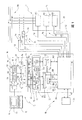
図1においては、本発明にかかる装置の全体を参照番号10で示している。
装置10は、ディスプレイユニット14を有する従来のコンピュータ12を備えている。このコンピュータ12は、コンピュータプログラム16を実行する。コンピュータプログラム16は、安全コントローラに対するユーザプログラムの書き込みを可能とする。このため、この技術分野では、コンピュータプログラム16をプログラミングツールと称することが多い。コンピュータ12はPCの形式であってもよく、ディスプレイユニット14はモニタの形式であってもよい。
In FIG. 1, the whole apparatus according to the present invention is indicated by
The
図1においては、安全回路の全体を参照番号18で示している。この安全回路は、全体を参照番号22で示した自動化設備を制御するように設計された安全コントローラ20を有する。自動化設備は、複数のアクチュエータ24と複数のセンサ26とを備えている。一例としては、ロボット等の負荷28が設備22に含まれた場合を図示している。
安全コントローラ20は、セーフティクリティカルなプロセスまたはアプリケーションの制御に必要なフェイルセーフ性を確保するため、2チャンネルの冗長設計となっている。図1には、2チャンネル設計の代表例として、2つの個別プロセッサ、すなわち、第1プロセッサ30および第2プロセッサ32を図示している。これら2つのプロセッサ30,32は、相互モニタリングおよびデータ交換が可能なように、双方向通信インターフェース34を介して互いに接続されている。安全コントローラ20の2つのチャンネルおよび2つのプロセッサ30,32は、システマティックエラーを大幅に削減するため、多様な設計、すなわち、互いに異なる設計とするのが好ましい。
In FIG. 1, the entire safety circuit is indicated by
The
参照番号36は、2つの各プロセッサ30,32に接続された入出力ユニットを示している。入出力ユニット36は、複数のセンサ26から複数の制御入力信号38を取得し、しかるべきデータフォーマットで2つの各プロセッサ30,32に転送する。さらに、入出力ユニット36は、各プロセッサ30,32に基づいて、複数のアクチュエータ24の駆動に用いられる複数の制御出力信号40を生成する。
参照番号42は、ユーザプログラムをマシンコードの形式で記憶させるためのプログラムメモリを示している。マシンコードは、装置10を用いて記述される。また、プログラムメモリ42がチップカードの形式であれば、コンピュータ12に直接接続しなくても、マシンコードひいてはユーザプログラムを簡単に交換可能である。あるいは、プログラムメモリ42は、たとえば、安全コントローラ20に常設のEEPROM等のメモリの形式であってもよい。
コンピュータプログラム16は、ディスプレイユニット14上にユーザインターフェース44を提供する。ユーザインターフェース44は、プログラマによるユーザプログラムの記述を可能にする。プログラマは、コンピュータ12に接続された入力ユニットを用いてコンピュータ12に入力を供給することにより、ユーザプログラムを記述する。
入力ユニットは、たとえばキーボードまたはマウスであってもよい。入力の概念は、ユーザプログラムを生成する際に使用するプログラミング言語によって異なる。たとえば、使用するプログラミング言語が構造化テキスト言語または命令リスト言語である場合、ユーザプログラムはテキスト入力によって記述される。これに対して、プログラミング言語として機能ブロック図を用いる場合、プログラマは、ユーザインターフェース44上に図示記号で表示された所定のプログラムモジュールをマウス等により選択して、ユーザプログラムを記述する。
The
The input unit may be a keyboard or a mouse, for example. The concept of input differs depending on the programming language used when generating the user program. For example, if the programming language used is a structured text language or an instruction list language, the user program is described by text input. On the other hand, when a functional block diagram is used as a programming language, a programmer describes a user program by selecting a predetermined program module displayed by a symbol on the user interface 44 with a mouse or the like.
コンピュータプログラム16には、ディスプレイモジュール46が含まれる。このディスプレイモジュール46は、プログラマが入力ユニットによって行った入力の取得および評価に使用する。まず初めに、ディスプレイモジュール46は、各入力を表すソースコード部品48を生成する。この部品は、ソースコードメモリ50に記憶される。次に、ディスプレイモジュール46は、ユーザインターフェース44上での図示記号の表示を促す。これらの図示記号は、プログラマによる入力ひいてはディスプレイモジュール46によるソースコード部品48を表す。
The
プログラマがユーザプログラムに必要なすべての入力を終えると、ソースコードメモリ50には、ソースコード52が含まれることになる。このソースコード52には、第1ソースコードコンポーネント54および第2ソースコードコンポーネント56が含まれる。
第1ソースコードコンポーネント54は、安全コントローラ20によって達成される安全タスクに必要な安全命令を表す。この安全命令は、アクチュエータを制御するための第1制御命令58である。第1制御命令58の処理には、安全関連プログラム変数のフェイルセーフ的な処理を伴う。第1制御命令は、安全制御命令と称することもできる。また、安全命令には、診断レポートを生成するための第1診断命令60が含まれる。第1診断命令は、安全診断命令と称することもできる。
When the programmer finishes all necessary inputs for the user program, the
The first
第2ソースコードコンポーネント56は、安全コントローラ20によって達成される標準タスクに必要な標準命令を表す。この標準命令は、アクチュエータを制御するための第2制御命令62である。第2制御命令62の処理には、フェイルセーフ処理が不要な非安全関連プログラム変数の処理を伴う。第2制御命令は、標準制御命令と称することもできる。また、標準命令には、診断レポートを生成するための第2診断命令64が含まれる。第2診断命令は、標準診断命令と称することもできる。
The second
マシンコード70は、2つのコンパイラ66,68により、ソースコードメモリ50に含まれるソースコード52から生成される。マシンコード70は、ゲートウェイ72を介して安全コントローラ20に送信され、プログラムメモリ42に記憶される。このマシンコード70の生成方法は、以下の通りである。
ソースコード52は、第1コンパイラ66に供給される。第1コンパイラ66は、第1マシンコード生成ユニット74と第1チェックサム決定ユニット76とを備えている。第1マシンコード生成ユニット74は、第1マシンコードコンポーネント78の生成に使用する。第1マシンコードコンポーネント78には、第1安全コード80および標準コード82が含まれる。第1安全コード80は、第1ソースコードコンポーネント54に基づいて生成される。この第1安全コード80には、第3制御命令84すなわち安全制御命令および第3診断命令86すなわち安全診断命令が含まれる。したがって、第1安全コード80の生成にあたっては、第1ソースコードコンポーネント54が完全にマシンコードに変換される。すなわち、第1制御命令58および第1診断命令60の両者がマシンコードに変換される。この場合、以下の関係性が有効である。すなわち、ソースコード末尾で利用可能な第1制御命令58は、マシンコード末尾で利用可能な第3制御命令84に対応し、ソースコード末尾で利用可能な第1診断命令60は、マシンコード末尾で利用可能な第3診断命令86に対応する。
The
The
標準コード82は、第2ソースコードコンポーネント56に基づいて生成される。この標準コード82には、第4制御命令88すなわち標準制御命令および第4診断命令90すなわち標準診断命令が含まれる。したがって、標準コード82の生成にあたっては、第2ソースコードコンポーネント56が完全にマシンコードに変換される。すなわち、第2制御命令62および第2診断命令64の両者がマシンコードに変換される。この場合、以下の関係性が有効である。すなわち、ソースコード末尾で利用可能な第2制御命令62は、マシンコード末尾で利用可能な第4制御命令88に対応し、ソースコード末尾で利用可能な第2診断命令64は、マシンコード末尾で利用可能な第4診断命令90に対応する。
また、ソースコード52は、第2コンパイラ68にも供給される。第2コンパイラ68は、第2マシンコード生成ユニット92と第2チェックサム決定ユニット94とを備えている。第2マシンコード生成ユニット92は、第2マシンコードコンポーネント96の生成に使用する。第2マシンコードコンポーネント96には、第2安全コード98が含まれる。第2安全コード98は、第1ソースコードコンポーネント54に基づいて生成され、第2ソースコードコンポーネント56は無視される。この第2安全コード98には、第5制御命令100すなわち安全制御命令のみが含まれ、診断命令は含まれない。したがって、第2安全コード98の生成にあたっては、第1ソースコードコンポーネント54が完全にマシンコードに変換されるわけではない。第1制御命令58だけがマシンコードに変換され、第1診断命令60は無視される。
The
第1チェックサム決定ユニット76は、第1安全コード80の第1チェックサム102の決定に使用する。ただし、第1チェックサム102は、第1安全コード80に含まれる第3制御命令84に対してのみ決定される。この場合、第1安全コード80に含まれる第3診断命令86は無視される。第1チェックサム102は、同様にゲートウェイ72を介して安全コントローラ20に送信され、プログラムメモリ42に記憶される。第2チェックサム決定ユニット94は、第2安全コード98の第2チェックサム104の決定に使用する。第2安全コード98には診断命令が一切含まれないため、第2チェックサム104の決定には、制御命令、とくに第5制御命令100のみを考慮する。第2チェックサム104も同様に、ゲートウェイ72を介して安全コントローラ20に送信され、プログラムメモリ42に記憶される。安全コントローラ20に記憶および保存された2つのチェックサム102,104を用いると、安全コントローラ20が実行するユーザプログラムの安全に関する部分が、一監督機関による承認プロセスにおいて確認され、その際に決定されたチェックサムにより封印された安全に関する部分と同一であるか否かを随時確認することができる。なお、承認に際して決定されたチェックサムについても、安全コントローラ20に記憶させるのが好ましい。
The first
2つのマシンコード生成ユニット74,92および2つのチェックサム決定ユニット76,94は、多様な設計とすれば都合が良い。あるいは、2つのチェックサム決定ユニット76,94を同一の設計とすることも考えられる。また、チェックサム決定ユニットを1つだけ設けることも考えられる。そして、このユニットを用いることにより、マシンコード生成ユニット74で生成された第1安全コード80およびマシンコード生成ユニット92で生成された第2安全コード98の両者に対して、それぞれのチェックサムを決定する。
The two machine
全体として、マシンコード70は、第1安全コード80、標準コード82、および第2安全コード98で構成されており、第1安全コード80および標準コード82は第1プロセッサ30と関連付けられている。一方、第2安全コード98は、第2プロセッサ32と関連付けられている。プログラマによって記述されたユーザプログラムの全体は、ソースコード52およびマシンコード70によって表される。
Overall, the
第1プロセッサ30は、ユーザプログラムの処理プロセスに基づいて、まず初めに現行第1安全命令106を実行し、次に、現行標準命令108を実行する。また、本質的にはこれと同時に、第2プロセッサ32では、現行第2安全命令110を実行する。現行第1安全命令106は、第3制御命令84に含まれる安全制御命令または第3診断命令86に含まれる安全診断命令であってもよい。現行標準命令108は、第4制御命令88に含まれる標準制御命令または第4診断命令90に含まれる標準診断命令であってもよい。現行第2安全命令110は、第5制御命令100に含まれる安全制御命令である。なお、安全制御命令は、安全関連制御命令とも称する。また、標準制御命令は、非安全関連制御命令とも称する。
The
現行標準命令108が標準制御命令である場合、第1プロセッサ30と入出力ユニット36との間では第1非安全関連データ112が交換される。この場合、第1プロセッサ30にはプログラム入力変数を用いてデータが供給されるが、その瞬時値は、非安全関連センサ116で生成された非安全関連制御入力信号114の値を表している。非安全関連センサ116は、たとえば閉ループ駆動制御に必要な入力変数を取得するセンサである。そのような変数としては、回転速度、角度、または速度等が挙げられる。また、非安全関連センサ116は、フェイルセーフ設計とはなっていない。入出力ユニット36にはプログラム出力変数を用いてデータが供給されるが、その瞬時値は、作動用に非安全関連アクチュエータ120に供給された非安全関連制御出力信号118の値を表している。非安全関連アクチュエータ120は、たとえばモータまたは作動シリンダであってもよい。非安全関連プログラム出力変数の瞬時値は、標準制御命令に応じて、非安全関連プログラム入力変数に基づいて決定される。
If the current
現行標準命令108が標準診断命令である場合、第1プロセッサ30と入出力ユニット36との間では第2非安全関連データ122が交換される。一例として、第1プロセッサ30には同様に、非安全関連制御入力信号114の瞬時値および/または非安全関連制御出力信号118の瞬時値が供給される。そして、供給された瞬時値に基づいて、制御される設備22のプロセス状態を規定することができる。また、診断ディスプレイユニット124により、しかるべき診断レポートが表示される。
If the current
現行第1安全命令106が安全制御命令である場合、第1プロセッサ30と入出力ユニット36との間では第1安全関連データ126が交換される。この場合、第1プロセッサ30には安全関連プログラム入力変数を用いてデータが供給されるが、その瞬時値は、安全関連センサ130で生成された安全関連制御入力信号128の値を表している。
安全関連センサ130は、たとえば緊急停止押しボタン、両手コントローラ、防護ドア、速度モニタリング装置、または安全関連パラメータを取得するその他のセンサである。入出力ユニット36には安全関連プログラム出力変数を用いてデータが供給されるが、その瞬時値は、作動用に安全関連アクチュエータ134に供給された安全関連制御出力信号132の値を表している。安全関連アクチュエータ134は、たとえば動作接点が電源136と負荷28との間に接続配置されたいわゆるコンタクタであって、負荷28に対して電源136を遮断する際に使用可能である。
When the current
The safety-related
しかるべき異常が発生した場合には、遮断によって、少なくとも負荷28を安全な状態に移行させることができる。安全関連プログラム出力変数の瞬時値は、安全制御命令に応じて、安全関連プログラム入力変数に基づいて決定される。
現行第1安全命令106が安全診断命令である場合、第1プロセッサ30と入出力ユニット36との間では第2安全関連データ138が交換される。一例として、第1プロセッサ30には同様に、安全関連制御入力信号128の瞬時値および/または安全関連制御出力信号132の瞬時値が供給される。そして、供給された瞬時値に基づいて、制御される設備22がどのプロセス状態となるかを規定することができる。また、診断ディスプレイユニット134により、しかるべき診断レポートが表示される。
When an appropriate abnormality occurs, at least the
If the current
現行第2安全命令110は、第1プロセッサ30で実行された現行第1安全命令106と手順が対応する安全制御命令である。この現行第2安全命令110には、第1安全関連データ126に対応する第3安全関連データ140が用いられる。
安全関連制御出力信号132の値は、上述の内容に従って、第1プロセッサ30および第2プロセッサ32の両者により生成されるが、これら2つのプロセッサ30,32で生成された値が制御出力信号132として同時に出力されることを意味するものではない。上述の内容は、処理対象の安全タスクに関して冗長な安全コントローラ20の設計を提供することのみを意図したものである。両プロセッサ30,32は、制御出力信号132の値を決定するように設計されている。安全コントローラ20が正常に動作している間は、第1プロセッサ30等の1つのプロセッサにより決定された値のみが制御出力信号132として出力される。
The current
The value of the safety-related
入出力ユニット36は、安全コントローラ20、安全関連センサ130、安全関連アクチュエータ134、および診断ディスプレイユニット124間での試験信号142の交換に用いられる。安全コントローラ20では、試験信号142を用いて、接続されたコンポーネントが正常に動作しているか否かを判定することができる。この判定が必要なのは、安全コントローラ20に接続された装置に異常が発生した場合に、制御される設備22の安全状態を直ちに保証しなければならないためである。
The input /
図2は、ソースコードに基づいてマシンコードを生成する手順を示している。この図では、第1ソースコードコンポーネント54ひいてはソースコードすなわちユーザプログラムの安全に関する範囲のみを考慮している。
第1ソースコードコンポーネント54には、参照番号160を付した第1安全制御命令FSSA1QCが含まれる。この場合、命名した名称には以下の意味がある。すなわち、FSは「フェイルセーフ(fail-safe)」を表し、この命令が安全関連制御命令であることを示している。SAは一般的に、「制御命令(Control Instruction)」を表す。そして、数字の1を末尾に付け加えることで安全制御命令が識別され、これにより、複数の安全制御命令の中から前記安全制御命令を識別可能となる。QCは、この命令がソースコード末尾の安全制御命令であることを示している。この命名法は、図2において標準として使用している。
FIG. 2 shows a procedure for generating machine code based on source code. In this figure, only the range related to the safety of the first
The first
参照番号162は、第2安全制御命令FSSA2QCを示している。これら2つの安全制御命令FSSA1QC,FSSA2QCは、第1制御命令58に含まれる。また、参照番号164,166はそれぞれ、第1安全診断命令FSDA1QCおよび第2安全診断命令FSDA2QCを示している。この場合、DAは一般的に、「診断命令(Diagnosis Instruction)」を表す。そして、たとえば数字の1を末尾に付け加えることにより、複数の安全診断命令の中から1つの安全診断命令を識別可能となる。
前記2つの安全診断命令FSDA1QC,FSDA2QCは、参照番号168を付した第1診断マーキングFSDM1QCおよび参照番号170を付した第2診断マーキングFSDM2QCによって包含、構成、または包囲されている。この場合、DMは一般的に、「診断マーキング(Diagnosis Marking)」を表す。そして、たとえば数字の1を末尾に付け加えることにより、診断マーキングの識別が可能となる。また、2つの診断マーキングFSDM1QC,FSDM2QCを用いることによって、コンパイルプロセス中に、第1ソースコードコンポーネント54に含まれる安全診断命令を識別可能となる。前記2つの安全診断命令FSDA1QC,FSDA2QCおよび2つの診断マーキングFSDM1QC,FSDM2QCはいずれも、第1診断命令60に含まれる。
The two safety diagnostic instructions FSDA1QC, FSDA2QC are included, configured or surrounded by a first diagnostic marking FSDM1QC labeled with
第1ソースコードコンポーネント54は、矢印172で示すように、第1コンパイラ66に供給される。この第1コンパイラ66は、第1チャンネルデータ174の生成に使用する。第1チャンネルデータ174は、第1プロセッサ30を含むチャンネルと関連付けられている。また、第3制御命令84を含む第1安全コード80の生成には、第1マシンコード生成ユニット74を使用する。この第3制御命令84は、参照番号176を付した第3安全制御命令FSSA1MCAおよび参照番号178を付した第4安全制御命令FSSA2MCAである。MCは、これらの命令がマシンコード末尾の安全制御命令であることを示している。文字Aは、これらの安全制御命令が第1プロセッサ30ひいてはチャンネルAに割り当て済みであることを示している。ソースコード末尾の安全制御命令とマシンコード末尾の安全制御命令との間では、以下の関係性が有効である。すなわち、マシンコード末尾の第3安全制御命令FSSA1MCAは、ソースコード末尾の第1安全制御命令FSSA1QCと関連付けられており、マシンコード末尾の第4安全制御命令FSSA2MCAは、ソースコード末尾の第2安全制御命令FSSA2QCと関連付けられている。
The first
また、第1安全コード80には、第3診断命令86が含まれる。この第3診断命令86は、参照番号180を付した第3安全診断命令FSDA1MCAおよび参照番号182を付した第4安全診断命令FSDA2MCAである。ソースコード末尾の安全診断命令とマシンコード末尾の安全診断命令との間では、以下の関係性が有効である。すなわち、マシンコード末尾の第3安全診断命令FSDA1MCAは、ソースコード末尾の第1安全診断命令FSDA1QCと関連付けられており、マシンコード末尾の第4安全診断命令FSDA2MCAは、ソースコード末尾の第2安全診断命令FSDA2QCと関連付けられている。
The
参照番号102を付した第1安全コード80の第1チェックサムCRCFSAの決定には、第1チェックサム決定ユニット76を使用する。文字列CRC(Cyclic Redundancy Check:巡回冗長検査)は、このチェックサム決定がCRC法に基づいて行われることを示している。第1チェックサムCRCFSAの生成には、第1安全コード80に含まれる安全制御命令、すなわち2つの安全制御命令FSSA1MCA,FSSA2MCAのみを考慮する。第1安全コード80に含まれる安全診断命令、すなわち2つの安全診断命令FSDA1MCA,FSDA2MCAは無視される。
The first
このように、第1チェックサム決定ユニット76は、第1ソースコードコンポーネント54に含まれる安全診断命令が第1チェックサムCRCFSAの決定に際して無視されるように設計されている。この目的のため、第1チェックサム決定ユニット76は、第1ソースコードコンポーネント54に含まれる診断マーキングを識別する。第1チェックサム決定ユニット76は、2つの診断マーキングFSDM1QC,FSDM2QCによって、これら2つの診断マーキング間に配置された安全命令が第1チェックサムCRCFSAの生成に際して無視可能となるようする必要がある。
Thus, the first
第1ソースコードコンポーネント54は、矢印184で示すように、第2コンパイラ68にも供給される。この第2コンパイラ68は、第2チャンネルデータ186の生成に使用する。第2チャンネルデータ186は、第2プロセッサ32を含むチャンネルを対象としている。また、第2安全コード98の生成には、第2マシンコード生成ユニット92を使用する。第2安全コード98には、第5制御命令100が含まれる。この第5制御命令100は、参照番号188を付した第5安全制御命令FSSA1MCBおよび参照番号190を付した第6安全制御命令FSSA2MCBである。文字Bは、これらの安全制御命令が第2プロセッサ32ひいてはチャンネルBに割り当て済みであることを示している。この場合、ソースコード末尾の安全制御命令とマシンコード末尾の安全制御命令との間では、以下の関係性が有効である。すなわち、マシンコード末尾の第5安全制御命令FSSA1MCBは、ソースコード末尾の第1安全制御命令FSSA1QCと関連付けられており、マシンコード末尾の第6安全制御命令FSSA2MCBは、ソースコード末尾の第2安全制御命令FSSA2QCと関連付けられている。
The first
この場合、第2マシンコード生成ユニット92は、第1ソースコードコンポーネント54に含まれる安全診断命令、すなわち2つの安全診断命令FSDA1QC,FSDA2QCが無視されるように設計されている。この目的のため、第2マシンコード生成ユニット92は、第1ソースコードコンポーネントに含まれる診断マーキング、すなわち2つの診断マーキングFSDM1QC,FSDM2QCを識別する。第2マシンコード生成ユニット92は、2つの診断マーキングFSDM1QC,FSDM2QCによって、これら2つの診断マーキング間に配置された安全命令が第1安全コード80の生成に際して無視可能となるようする必要がある。これら2つの診断マーキングは、両者間に安全診断命令として配置された安全命令として識別される。
In this case, the second machine
参照番号104を付した第2安全コード98の第2チェックサムCRCFSBの決定には、第2チェックサム決定ユニット94を使用する。第2安全コード98には安全制御命令のみが含まれるため、第2チェックサムCRCFSBの決定には安全診断命令を考慮しない。
第1チェックサムCRCFSAの決定に際しては、マシンコード末尾の2つの安全診断命令FSDA1MCA,FSDA2MCAが無視されるため、ソースコード末尾の2つの安全診断命令FSDA1QC,FSDA2QCも無視される。
The second
In determining the first checksum CRCFSA, the two safety diagnostic instructions FSDA1MCA and FSDA2MCA at the end of the machine code are ignored, so the two safety diagnostic instructions FSDA1QC and FSDA2QC at the end of the source code are also ignored.
Claims (6)
ユーザプログラムのソースコード(52)を生成するステップであって、前記ソースコード(52)が前記アクチュエータ(24)を制御するための複数の制御命令(160,162)および診断レポートを生成するための複数の診断命令(164,166)を含み、前記制御命令(160,162)の実行中に安全関連プログラム変数がフェイルセーフ的に処理されるステップと、
前記ソースコード(52)に基づいてマシンコード(70)を生成するステップと、
少なくとも1つのチェックサム(102,104)を決定するステップであって、前記チェックサム(102,104)が前記マシンコード(70)の少なくとも一部に対して決定され、前記チェックサム(102,104)の決定に際して前記診断命令(164,166)が無視されるステップと、
を含むことを特徴とする方法。 In a method for generating a user program for use in a safety controller (20) designed to control an automated facility (22) having a plurality of sensors (26) and a plurality of actuators (24),
Generating a user program source code (52) for generating a plurality of control instructions (160, 162) and a diagnostic report for the source code (52) to control the actuator (24); Including a plurality of diagnostic instructions (164, 166), wherein safety-related program variables are processed fail-safe during execution of the control instructions (160, 162);
Generating machine code (70) based on said source code (52);
Determining at least one checksum (102, 104), wherein the checksum (102, 104) is determined for at least a portion of the machine code (70) and the checksum (102, 104) is determined. ) Ignoring the diagnostic instructions (164, 166) in determining
A method comprising the steps of:
ユーザプログラムのソースコード(52)を生成するユニット(12,14,16)であって、前記ソースコード(52)が前記アクチュエータ(24)を制御するための複数の制御命令(160,162)および診断レポートを生成するための複数の診断命令(164,166)を含み、前記制御命令(160,162)の実行中に安全関連プログラム変数がフェイルセーフ的に処理されるユニット(12,14,16)と、
前記ソースコード(52)に基づいてマシンコード(70)を生成するユニット(74,92)と、
少なくとも1つのチェックサム(102,104)を決定するユニット(76,94)であって、前記チェックサム(102,104)が前記マシンコード(70)の少なくとも一部に対して決定され、前記チェックサム(102,104)の決定に際して前記診断命令(164,166)が無視されるユニット(76,94)と、
を備えたことを特徴とする装置。 In a user program generator for use in a safety controller (20) designed to control an automated facility (22) having a plurality of sensors (26) and a plurality of actuators (24),
A unit (12, 14, 16) for generating a source code (52) of a user program, wherein the source code (52) controls a plurality of control instructions (160, 162) for controlling the actuator (24); A unit (12, 14, 16) that includes a plurality of diagnostic instructions (164, 166) for generating a diagnostic report, and in which safety-related program variables are processed in a fail-safe manner during execution of the control instructions (160, 162). )When,
Units (74, 92) for generating machine code (70) based on said source code (52);
A unit (76, 94) for determining at least one checksum (102, 104), wherein the checksum (102, 104) is determined for at least a part of the machine code (70); A unit (76, 94) in which the diagnostic instruction (164, 166) is ignored in determining the thumb (102, 104);
A device characterized by comprising:
Applications Claiming Priority (3)
| Application Number | Priority Date | Filing Date | Title |
|---|---|---|---|
| DE102009019089.9 | 2009-04-20 | ||
| DE102009019089A DE102009019089A1 (en) | 2009-04-20 | 2009-04-20 | Method and device for creating a user program for a safety control |
| PCT/EP2010/002435 WO2010121795A1 (en) | 2009-04-20 | 2010-04-20 | Method and apparatus for creating an application program for a safety-related control unit |
Publications (2)
| Publication Number | Publication Date |
|---|---|
| JP2012524352A JP2012524352A (en) | 2012-10-11 |
| JP5436660B2 true JP5436660B2 (en) | 2014-03-05 |
Family
ID=42543305
Family Applications (1)
| Application Number | Title | Priority Date | Filing Date |
|---|---|---|---|
| JP2012506391A Active JP5436660B2 (en) | 2009-04-20 | 2010-04-20 | Method and apparatus for generating application program for safety-related control unit |
Country Status (8)
| Country | Link |
|---|---|
| US (1) | US8910131B2 (en) |
| EP (1) | EP2422271B1 (en) |
| JP (1) | JP5436660B2 (en) |
| CN (1) | CN102460397B (en) |
| DE (1) | DE102009019089A1 (en) |
| ES (1) | ES2417309T3 (en) |
| HK (1) | HK1166533A1 (en) |
| WO (1) | WO2010121795A1 (en) |
Families Citing this family (19)
| Publication number | Priority date | Publication date | Assignee | Title |
|---|---|---|---|---|
| DE102005061393A1 (en) * | 2005-12-22 | 2007-07-05 | Robert Bosch Gmbh | Software module distributing method for control device of motor vehicle, involves classifying and allocating software modules to control devices based on security-relevant classification features |
| EP2495625B1 (en) * | 2011-03-04 | 2020-06-17 | Siemens Aktiengesellschaft | Method and programming system for the authentication of a security program of an automation device |
| JP5816019B2 (en) * | 2011-07-29 | 2015-11-17 | Ntn株式会社 | Control device for steer-by-wire steering system with redundancy function |
| DE202012013193U1 (en) | 2012-06-26 | 2015-05-06 | INTER CONTROL Hermann Köhler Elektrik GmbH & Co KG | Device for a safety-critical application |
| US8938710B2 (en) * | 2012-12-28 | 2015-01-20 | The Mathworks, Inc. | Preventing interference between subsystem blocks at a design time |
| DE102013218814A1 (en) * | 2013-09-19 | 2015-03-19 | Siemens Aktiengesellschaft | Method for operating a safety-critical system |
| JP6045716B2 (en) * | 2013-10-31 | 2016-12-14 | 三菱電機株式会社 | Program creation device, program creation method, and program |
| JP5619331B1 (en) * | 2014-03-25 | 2014-11-05 | 三菱電機株式会社 | Programming device and execution code generation method |
| DE102014208774A1 (en) * | 2014-05-09 | 2015-11-12 | Siemens Aktiengesellschaft | Computing device with a manipulation detection and a method for detecting a manipulation of a computing device |
| KR101906823B1 (en) * | 2016-03-07 | 2018-12-05 | 주식회사 럭스로보 | Multi-module compilation system, multi-module compilation method, and non-transitory computer-readable storage medium |
| JP6520772B2 (en) * | 2016-03-14 | 2019-05-29 | オムロン株式会社 | Evaluation system, evaluation program and evaluation method |
| EP3355230A1 (en) * | 2017-01-25 | 2018-08-01 | Siemens Aktiengesellschaft | Method and apparatus for computer-assisted preparing and running of a control function |
| EP3499324B1 (en) * | 2017-12-12 | 2021-01-27 | Sick Ag | Method of modular verification of a configuration of a device |
| US10503634B1 (en) * | 2018-05-25 | 2019-12-10 | Microsoft Technology Licensing, Llc | Semantic comparison of computer compiler traces |
| DE102018120344A1 (en) * | 2018-08-21 | 2020-02-27 | Pilz Gmbh & Co. Kg | Automation system for monitoring a safety-critical process |
| DE102018120347A1 (en) * | 2018-08-21 | 2020-02-27 | Pilz Gmbh & Co. Kg | Automation system for monitoring a safety-critical process |
| DE102018129354A1 (en) | 2018-11-21 | 2020-05-28 | Phoenix Contact Gmbh & Co. Kg | Process for processing application programs on a distributed automation system |
| DE102021004639A1 (en) | 2021-09-14 | 2023-03-16 | Hydac Electronic Gmbh | Sensor device for determining a size |
| CN117032940B (en) * | 2023-10-08 | 2024-02-13 | 北京小米移动软件有限公司 | System, method and device for scheduling resources, electronic equipment and storage medium |
Family Cites Families (24)
| Publication number | Priority date | Publication date | Assignee | Title |
|---|---|---|---|---|
| KR920001574B1 (en) | 1987-05-29 | 1992-02-18 | 후지쓰 가부시끼가이샤 | Method and system for checking errors of signal being transferred trough transmission line |
| JPH06242957A (en) * | 1993-02-16 | 1994-09-02 | Fujitsu Ltd | Program execution controller |
| JPH07295602A (en) * | 1994-04-22 | 1995-11-10 | Shimadzu Corp | Dual control unit |
| US6868538B1 (en) * | 1996-04-12 | 2005-03-15 | Fisher-Rosemount Systems, Inc. | Object-oriented programmable controller |
| JPH10187202A (en) * | 1996-12-24 | 1998-07-14 | Toshiba Corp | Microprocessor controller |
| US6161051A (en) * | 1998-05-08 | 2000-12-12 | Rockwell Technologies, Llc | System, method and article of manufacture for utilizing external models for enterprise wide control |
| US6201996B1 (en) * | 1998-05-29 | 2001-03-13 | Control Technology Corporationa | Object-oriented programmable industrial controller with distributed interface architecture |
| US6647301B1 (en) * | 1999-04-22 | 2003-11-11 | Dow Global Technologies Inc. | Process control system with integrated safety control system |
| DE10108962A1 (en) * | 2001-02-20 | 2002-09-12 | Pilz Gmbh & Co | Method and device for programming a safety controller |
| WO2003001343A2 (en) * | 2001-06-22 | 2003-01-03 | Wonderware Corporation | Supervisory process control and manufacturing information system application having an extensible component model |
| US6880149B2 (en) * | 2002-04-01 | 2005-04-12 | Pace Anti-Piracy | Method for runtime code integrity validation using code block checksums |
| SE0202019D0 (en) * | 2002-06-28 | 2002-06-28 | Abb As | Rehabilitation of a compiler for safety control |
| US7076311B2 (en) * | 2002-07-09 | 2006-07-11 | Rockwell Automation Technologies, Inc. | Configurable safety system for implementation on industrial system and method of implementing same |
| DE10240584A1 (en) * | 2002-08-28 | 2004-03-11 | Pilz Gmbh & Co. | Safety control system for fault protected operation of critical process such as occurs in machine system operation |
| SE524639C2 (en) * | 2002-10-15 | 2004-09-07 | Abb As | Error detection in an industrial controller under safety-related control |
| US7818729B1 (en) * | 2003-09-15 | 2010-10-19 | Thomas Plum | Automated safe secure techniques for eliminating undefined behavior in computer software |
| US7203885B2 (en) * | 2003-09-30 | 2007-04-10 | Rockwell Automation Technologies, Inc. | Safety protocol for industrial controller |
| DE102004035456A1 (en) * | 2004-07-22 | 2006-02-16 | Robert Bosch Gmbh | Method for controlling technical processes and device for monitoring the execution of a control program on a calculator |
| DE102004055971B8 (en) * | 2004-11-19 | 2012-06-21 | Kw-Software Gmbh | Method and device for safe parameterization according to IEC 61508 SIL 1 to 3 or EN 954-1 Category 1 to 4 |
| DE102005046696B4 (en) * | 2005-09-29 | 2009-11-05 | Fujitsu Siemens Computers Gmbh | A method for generating protected program code and method for executing program code of a protected computer program and computer program product |
| US8161465B2 (en) * | 2006-07-27 | 2012-04-17 | Oracle International Corporation | Method and apparatus for performing conditional compilation |
| JP4849261B2 (en) * | 2007-05-14 | 2012-01-11 | オムロン株式会社 | Safety application creation support device |
| JP5174798B2 (en) * | 2009-01-26 | 2013-04-03 | 三菱電機株式会社 | Safety diagnostic device and safety diagnostic method for safety control program |
| DE102009011679A1 (en) * | 2009-02-23 | 2010-08-26 | Pilz Gmbh & Co. Kg | Method and device for creating a user program for a safety control |
-
2009
- 2009-04-20 DE DE102009019089A patent/DE102009019089A1/en not_active Withdrawn
-
2010
- 2010-04-20 CN CN201080027502.3A patent/CN102460397B/en active Active
- 2010-04-20 WO PCT/EP2010/002435 patent/WO2010121795A1/en active Application Filing
- 2010-04-20 ES ES10720342T patent/ES2417309T3/en active Active
- 2010-04-20 JP JP2012506391A patent/JP5436660B2/en active Active
- 2010-04-20 EP EP10720342.4A patent/EP2422271B1/en active Active
-
2011
- 2011-10-19 US US13/276,882 patent/US8910131B2/en active Active
-
2012
- 2012-07-23 HK HK12107171.2A patent/HK1166533A1/en not_active IP Right Cessation
Also Published As
| Publication number | Publication date |
|---|---|
| ES2417309T3 (en) | 2013-08-07 |
| HK1166533A1 (en) | 2012-11-02 |
| WO2010121795A1 (en) | 2010-10-28 |
| DE102009019089A1 (en) | 2010-11-04 |
| CN102460397B (en) | 2016-01-20 |
| EP2422271B1 (en) | 2013-06-19 |
| CN102460397A (en) | 2012-05-16 |
| JP2012524352A (en) | 2012-10-11 |
| EP2422271A1 (en) | 2012-02-29 |
| US20120096428A1 (en) | 2012-04-19 |
| US8910131B2 (en) | 2014-12-09 |
Similar Documents
| Publication | Publication Date | Title |
|---|---|---|
| JP5436660B2 (en) | Method and apparatus for generating application program for safety-related control unit | |
| JP5636378B2 (en) | Method and apparatus for creating a user program for a safety controller and computer program | |
| JP5911922B2 (en) | Safety-related control unit and control method for automated equipment | |
| JP2004524620A (en) | Method and apparatus for programming a fail-safe control system | |
| US8910121B2 (en) | Method and device for programming an industrial controller | |
| US10437571B2 (en) | Method for programming a safety controller | |
| JP4900607B2 (en) | Safety control system | |
| JP2012510099A (en) | Method and apparatus for creating user program for safety control device | |
| CN108572611B (en) | Information processing apparatus, information processing method, and computer-readable recording medium | |
| US7386359B2 (en) | Device and method for testing machine tools and production machines | |
| JP4849261B2 (en) | Safety application creation support device | |
| JP5815504B2 (en) | Safety controller and method for controlling automation equipment | |
| JP7000703B2 (en) | Information processing equipment, information processing methods, and information processing programs | |
| JP2008027156A (en) | Simulation device | |
| US11169510B2 (en) | Engineering system and method for planning an automation system | |
| US9563181B2 (en) | Method for operating an automation system | |
| JP4556787B2 (en) | Programmable controller editing device | |
| JP5174798B2 (en) | Safety diagnostic device and safety diagnostic method for safety control program | |
| Laible et al. | A fail-safe dual channel robot control for surgery applications | |
| JP6705848B2 (en) | Control device and control system | |
| Soliman et al. | A methodology to upgrade legacy industrial systems to meet safety regulations | |
| ENGİN | FUNCTIONAL SAFETY IN PROGRAMMABLE LOGIC CONTROLLERS | |
| JP4061555B2 (en) | Process control safety monitoring system | |
| CN116438490A (en) | Control device |
Legal Events
| Date | Code | Title | Description |
|---|---|---|---|
| A621 | Written request for application examination |
Free format text: JAPANESE INTERMEDIATE CODE: A621 Effective date: 20130208 |
|
| TRDD | Decision of grant or rejection written | ||
| A01 | Written decision to grant a patent or to grant a registration (utility model) |
Free format text: JAPANESE INTERMEDIATE CODE: A01 Effective date: 20131114 |
|
| A61 | First payment of annual fees (during grant procedure) |
Free format text: JAPANESE INTERMEDIATE CODE: A61 Effective date: 20131210 |
|
| R150 | Certificate of patent or registration of utility model |
Ref document number: 5436660 Country of ref document: JP Free format text: JAPANESE INTERMEDIATE CODE: R150 Free format text: JAPANESE INTERMEDIATE CODE: R150 |
|
| R250 | Receipt of annual fees |
Free format text: JAPANESE INTERMEDIATE CODE: R250 |
|
| R250 | Receipt of annual fees |
Free format text: JAPANESE INTERMEDIATE CODE: R250 |
|
| R250 | Receipt of annual fees |
Free format text: JAPANESE INTERMEDIATE CODE: R250 |
|
| R250 | Receipt of annual fees |
Free format text: JAPANESE INTERMEDIATE CODE: R250 |
|
| R250 | Receipt of annual fees |
Free format text: JAPANESE INTERMEDIATE CODE: R250 |
|
| R250 | Receipt of annual fees |
Free format text: JAPANESE INTERMEDIATE CODE: R250 |
|
| R250 | Receipt of annual fees |
Free format text: JAPANESE INTERMEDIATE CODE: R250 |
|
| R250 | Receipt of annual fees |
Free format text: JAPANESE INTERMEDIATE CODE: R250 |