JP5408691B2 - Sealed secondary battery - Google Patents
Sealed secondary battery Download PDFInfo
- Publication number
- JP5408691B2 JP5408691B2 JP2008213831A JP2008213831A JP5408691B2 JP 5408691 B2 JP5408691 B2 JP 5408691B2 JP 2008213831 A JP2008213831 A JP 2008213831A JP 2008213831 A JP2008213831 A JP 2008213831A JP 5408691 B2 JP5408691 B2 JP 5408691B2
- Authority
- JP
- Japan
- Prior art keywords
- current collector
- positive electrode
- metal foil
- secondary battery
- sealed secondary
- Prior art date
- Legal status (The legal status is an assumption and is not a legal conclusion. Google has not performed a legal analysis and makes no representation as to the accuracy of the status listed.)
- Active
Links
- 239000011888 foil Substances 0.000 claims description 99
- 229910052751 metal Inorganic materials 0.000 claims description 86
- 239000002184 metal Substances 0.000 claims description 86
- 239000000203 mixture Substances 0.000 claims description 59
- 230000002093 peripheral effect Effects 0.000 claims description 46
- 238000004804 winding Methods 0.000 claims description 30
- 238000003466 welding Methods 0.000 claims description 16
- XAGFODPZIPBFFR-UHFFFAOYSA-N aluminium Chemical group [Al] XAGFODPZIPBFFR-UHFFFAOYSA-N 0.000 claims description 13
- 229910052782 aluminium Inorganic materials 0.000 claims description 12
- RYGMFSIKBFXOCR-UHFFFAOYSA-N Copper Chemical group [Cu] RYGMFSIKBFXOCR-UHFFFAOYSA-N 0.000 claims description 10
- 239000000853 adhesive Substances 0.000 claims description 8
- 230000001070 adhesive effect Effects 0.000 claims description 8
- 239000004020 conductor Substances 0.000 claims description 8
- PXHVJJICTQNCMI-UHFFFAOYSA-N Nickel Chemical compound [Ni] PXHVJJICTQNCMI-UHFFFAOYSA-N 0.000 claims description 6
- 239000011889 copper foil Substances 0.000 claims description 6
- 229910052802 copper Inorganic materials 0.000 claims description 4
- 239000010949 copper Substances 0.000 claims description 4
- 229910000838 Al alloy Inorganic materials 0.000 claims description 3
- RTAQQCXQSZGOHL-UHFFFAOYSA-N Titanium Chemical compound [Ti] RTAQQCXQSZGOHL-UHFFFAOYSA-N 0.000 claims description 3
- 229910052759 nickel Inorganic materials 0.000 claims description 3
- 229910052709 silver Inorganic materials 0.000 claims description 3
- 239000004332 silver Substances 0.000 claims description 3
- 239000010935 stainless steel Substances 0.000 claims description 3
- 229910001220 stainless steel Inorganic materials 0.000 claims description 3
- 239000010936 titanium Substances 0.000 claims description 3
- 229910052719 titanium Inorganic materials 0.000 claims description 3
- 238000000034 method Methods 0.000 description 45
- 238000012360 testing method Methods 0.000 description 39
- 230000000052 comparative effect Effects 0.000 description 27
- 230000003014 reinforcing effect Effects 0.000 description 24
- 238000005304 joining Methods 0.000 description 21
- 239000000463 material Substances 0.000 description 14
- 230000035882 stress Effects 0.000 description 10
- 238000004519 manufacturing process Methods 0.000 description 9
- 230000000694 effects Effects 0.000 description 8
- 238000005259 measurement Methods 0.000 description 8
- 239000002033 PVDF binder Substances 0.000 description 7
- 239000008151 electrolyte solution Substances 0.000 description 7
- 229920002981 polyvinylidene fluoride Polymers 0.000 description 7
- 238000007789 sealing Methods 0.000 description 7
- 239000011230 binding agent Substances 0.000 description 5
- 230000007547 defect Effects 0.000 description 5
- XEEYBQQBJWHFJM-UHFFFAOYSA-N Iron Chemical compound [Fe] XEEYBQQBJWHFJM-UHFFFAOYSA-N 0.000 description 4
- SECXISVLQFMRJM-UHFFFAOYSA-N N-Methylpyrrolidone Chemical compound CN1CCCC1=O SECXISVLQFMRJM-UHFFFAOYSA-N 0.000 description 4
- 230000002950 deficient Effects 0.000 description 4
- 230000006872 improvement Effects 0.000 description 4
- -1 polytetrafluoroethylene Polymers 0.000 description 4
- 239000007774 positive electrode material Substances 0.000 description 4
- 230000002787 reinforcement Effects 0.000 description 4
- 229920005989 resin Polymers 0.000 description 4
- 239000011347 resin Substances 0.000 description 4
- 239000002002 slurry Substances 0.000 description 4
- OKTJSMMVPCPJKN-UHFFFAOYSA-N Carbon Chemical compound [C] OKTJSMMVPCPJKN-UHFFFAOYSA-N 0.000 description 3
- 239000007773 negative electrode material Substances 0.000 description 3
- 239000003960 organic solvent Substances 0.000 description 3
- 229920006267 polyester film Polymers 0.000 description 3
- 230000008569 process Effects 0.000 description 3
- 150000003839 salts Chemical class 0.000 description 3
- XTHFKEDIFFGKHM-UHFFFAOYSA-N Dimethoxyethane Chemical compound COCCOC XTHFKEDIFFGKHM-UHFFFAOYSA-N 0.000 description 2
- 239000004593 Epoxy Substances 0.000 description 2
- KMTRUDSVKNLOMY-UHFFFAOYSA-N Ethylene carbonate Chemical compound O=C1OCCO1 KMTRUDSVKNLOMY-UHFFFAOYSA-N 0.000 description 2
- 229910013684 LiClO 4 Inorganic materials 0.000 description 2
- 229910012851 LiCoO 2 Inorganic materials 0.000 description 2
- 239000004698 Polyethylene Substances 0.000 description 2
- 239000011149 active material Substances 0.000 description 2
- 239000011248 coating agent Substances 0.000 description 2
- 238000000576 coating method Methods 0.000 description 2
- 239000000470 constituent Substances 0.000 description 2
- 238000007599 discharging Methods 0.000 description 2
- 238000001035 drying Methods 0.000 description 2
- 229910002804 graphite Inorganic materials 0.000 description 2
- 239000010439 graphite Substances 0.000 description 2
- 229910052742 iron Inorganic materials 0.000 description 2
- 239000005486 organic electrolyte Substances 0.000 description 2
- 229920000573 polyethylene Polymers 0.000 description 2
- 239000000843 powder Substances 0.000 description 2
- 238000005096 rolling process Methods 0.000 description 2
- 239000000243 solution Substances 0.000 description 2
- 239000002904 solvent Substances 0.000 description 2
- 208000031872 Body Remains Diseases 0.000 description 1
- 229910015015 LiAsF 6 Inorganic materials 0.000 description 1
- 229910013063 LiBF 4 Inorganic materials 0.000 description 1
- 229910015643 LiMn 2 O 4 Inorganic materials 0.000 description 1
- 229910013290 LiNiO 2 Inorganic materials 0.000 description 1
- 229910013870 LiPF 6 Inorganic materials 0.000 description 1
- HBBGRARXTFLTSG-UHFFFAOYSA-N Lithium ion Chemical compound [Li+] HBBGRARXTFLTSG-UHFFFAOYSA-N 0.000 description 1
- 229920003171 Poly (ethylene oxide) Polymers 0.000 description 1
- 239000005062 Polybutadiene Substances 0.000 description 1
- 239000004793 Polystyrene Substances 0.000 description 1
- 206010037660 Pyrexia Diseases 0.000 description 1
- 239000002174 Styrene-butadiene Substances 0.000 description 1
- 239000006230 acetylene black Substances 0.000 description 1
- 229910021383 artificial graphite Inorganic materials 0.000 description 1
- 230000008901 benefit Effects 0.000 description 1
- 230000015572 biosynthetic process Effects 0.000 description 1
- MTAZNLWOLGHBHU-UHFFFAOYSA-N butadiene-styrene rubber Chemical compound C=CC=C.C=CC1=CC=CC=C1 MTAZNLWOLGHBHU-UHFFFAOYSA-N 0.000 description 1
- 239000003575 carbonaceous material Substances 0.000 description 1
- 230000008859 change Effects 0.000 description 1
- 230000008602 contraction Effects 0.000 description 1
- 238000007796 conventional method Methods 0.000 description 1
- 229920001577 copolymer Polymers 0.000 description 1
- 230000001419 dependent effect Effects 0.000 description 1
- IEJIGPNLZYLLBP-UHFFFAOYSA-N dimethyl carbonate Chemical compound COC(=O)OC IEJIGPNLZYLLBP-UHFFFAOYSA-N 0.000 description 1
- 238000009826 distribution Methods 0.000 description 1
- 239000003792 electrolyte Substances 0.000 description 1
- 238000005516 engineering process Methods 0.000 description 1
- 229920006332 epoxy adhesive Polymers 0.000 description 1
- 230000006355 external stress Effects 0.000 description 1
- 230000020169 heat generation Effects 0.000 description 1
- 238000009863 impact test Methods 0.000 description 1
- 229910052738 indium Inorganic materials 0.000 description 1
- 238000010030 laminating Methods 0.000 description 1
- 229910001416 lithium ion Inorganic materials 0.000 description 1
- 229910044991 metal oxide Inorganic materials 0.000 description 1
- 150000004706 metal oxides Chemical class 0.000 description 1
- 229910021382 natural graphite Inorganic materials 0.000 description 1
- 239000000615 nonconductor Substances 0.000 description 1
- 239000002245 particle Substances 0.000 description 1
- 229920002857 polybutadiene Polymers 0.000 description 1
- 229920000098 polyolefin Polymers 0.000 description 1
- 229920002223 polystyrene Polymers 0.000 description 1
- 229920001343 polytetrafluoroethylene Polymers 0.000 description 1
- 239000004810 polytetrafluoroethylene Substances 0.000 description 1
- RUOJZAUFBMNUDX-UHFFFAOYSA-N propylene carbonate Chemical compound CC1COC(=O)O1 RUOJZAUFBMNUDX-UHFFFAOYSA-N 0.000 description 1
- 238000011160 research Methods 0.000 description 1
- 239000007784 solid electrolyte Substances 0.000 description 1
- 239000011115 styrene butadiene Substances 0.000 description 1
- 229920003048 styrene butadiene rubber Polymers 0.000 description 1
- 239000000126 substance Substances 0.000 description 1
- 230000001629 suppression Effects 0.000 description 1
- 230000009466 transformation Effects 0.000 description 1
Images


Classifications
-
- Y—GENERAL TAGGING OF NEW TECHNOLOGICAL DEVELOPMENTS; GENERAL TAGGING OF CROSS-SECTIONAL TECHNOLOGIES SPANNING OVER SEVERAL SECTIONS OF THE IPC; TECHNICAL SUBJECTS COVERED BY FORMER USPC CROSS-REFERENCE ART COLLECTIONS [XRACs] AND DIGESTS
- Y02—TECHNOLOGIES OR APPLICATIONS FOR MITIGATION OR ADAPTATION AGAINST CLIMATE CHANGE
- Y02E—REDUCTION OF GREENHOUSE GAS [GHG] EMISSIONS, RELATED TO ENERGY GENERATION, TRANSMISSION OR DISTRIBUTION
- Y02E60/00—Enabling technologies; Technologies with a potential or indirect contribution to GHG emissions mitigation
- Y02E60/10—Energy storage using batteries
-
- Y—GENERAL TAGGING OF NEW TECHNOLOGICAL DEVELOPMENTS; GENERAL TAGGING OF CROSS-SECTIONAL TECHNOLOGIES SPANNING OVER SEVERAL SECTIONS OF THE IPC; TECHNICAL SUBJECTS COVERED BY FORMER USPC CROSS-REFERENCE ART COLLECTIONS [XRACs] AND DIGESTS
- Y02—TECHNOLOGIES OR APPLICATIONS FOR MITIGATION OR ADAPTATION AGAINST CLIMATE CHANGE
- Y02P—CLIMATE CHANGE MITIGATION TECHNOLOGIES IN THE PRODUCTION OR PROCESSING OF GOODS
- Y02P70/00—Climate change mitigation technologies in the production process for final industrial or consumer products
- Y02P70/50—Manufacturing or production processes characterised by the final manufactured product
Description
本発明は、情報機器、家電機器などに用いられ、とくに携帯機器での使用に好適な、電極体およびセパレータからなる捲回体を有する密閉型二次電池に関する。 The present invention relates to a sealed secondary battery having a wound body composed of an electrode body and a separator, which is used in information equipment, home appliances, and the like, and is particularly suitable for use in portable equipment.
近年、エレクトロニクス技術の進歩により、電子機器の小型化および高機能化が可能となった。その結果、携帯可能な情報機器や家電機器などの民生用を中心とした携帯機器の市場が急成長を遂げている。これらの機器の駆動用電源として用いるために、エネルギー密度が高く、かつ長寿命の、リチウムイオン二次電池を代表とする密閉型二次電池の開発が行われてきた。このような中でエネルギー密度のさらなる向上のために、密閉型二次電池を構成する電池要素である正極、負極の電極体の改良や、絶縁性のシートであるセパレータの薄膜化が進められている。このうち正極および負極の電極体は一般に集電体に合剤層を塗布して圧延することで作製されるが、作製時の圧延方法の改良や、合剤層を構成する活物質材料の粒度分布の調整などが行われている。またセパレータについても、高い突き刺し強度や引張り強度を維持したままでの薄膜化などが検討されている。 In recent years, advances in electronics technology have made electronic devices smaller and more functional. As a result, the market for portable devices, mainly consumer products such as portable information devices and home appliances, has grown rapidly. In order to use as a power source for driving these devices, a sealed secondary battery represented by a lithium ion secondary battery having a high energy density and a long life has been developed. Under these circumstances, in order to further improve the energy density, improvements have been made to the positive and negative electrode bodies, which are the battery elements constituting the sealed secondary battery, and the separator, which is an insulating sheet, has been made thinner. Yes. Of these, the positive and negative electrode bodies are generally produced by applying a mixture layer to a current collector and rolling, but the improvement of the rolling method at the time of production and the particle size of the active material constituting the mixture layer The distribution is adjusted. As for the separator, it has been studied to reduce the thickness of the separator while maintaining high piercing strength and tensile strength.
密閉型二次電池を作製するためには、まず帯状形状の正極電極体、負極電極体およびセパレータの三者を互いに積層して積層体を作製し、これを捲回して捲回体を作製する。この際に捲回体の最外周部の正極電極体、負極電極体の端部領域には、それぞれ正極リード、負極リードを接合しておき、外部への取り出し電極とする。次いでこの捲回体を円筒形状のまま、もしくはこれを捲回体の側面方向に圧迫し、扁平形状としてから外装缶に挿入し、その後に外装缶を密封して密閉型二次電池とする方法が一般的である。 In order to fabricate a sealed secondary battery, first, a three-piece structure of a belt-like positive electrode body, a negative electrode body and a separator is laminated together to produce a laminated body, which is wound to produce a wound body. . At this time, a positive electrode lead and a negative electrode lead are bonded to the positive electrode body and the negative electrode body at the outermost peripheral portion of the wound body, respectively, so as to be taken out to the outside. Next, the wound body remains in a cylindrical shape, or is pressed into the side surface direction of the wound body to form a flat shape and then inserted into the outer can, and then the outer can is sealed to form a sealed secondary battery Is common.
このような密閉型二次電池では、一連の組立時や電池の使用中に捲回体に加えられる外部応力や、電池の充電および放電による正極電極体および負極電極体の膨張、収縮に伴って捲回体に加えられる応力歪みなどにより、捲回体を構成する正極電極体や負極電極体の一部(主に集電体)に破断が生じる可能性が指摘されていた。密閉型二次電池にこのような電極体の破断が生じると、何の対策も施されていない場合は電池の内部抵抗が急激に増加することとなり、これによって電池の出力の低下や電池内部での発熱などが生じる可能性があった。 In such a sealed secondary battery, external stress applied to the wound body during a series of assembly or use of the battery, and expansion and contraction of the positive electrode body and the negative electrode body due to charging and discharging of the battery. It has been pointed out that the positive electrode body and the part of the negative electrode body (mainly the current collector) constituting the wound body may break due to stress strain applied to the wound body. When such a breakage of the electrode body occurs in a sealed secondary battery, the internal resistance of the battery suddenly increases if no countermeasures are taken. There was a possibility that a fever would occur.
特許文献1は、このような密閉型二次電池の捲回体を構成する電極体の端部領域に剛性補強部を設け、とくに捲回体の作製時に電極体の端部領域が破断することを防止したものである。特許文献1では捲回体を構成する正極および負極電極体の巻き始め部分において集電体の端部領域の表面に新たにフィルムを付着させるか、もしくは端部領域の集電体を折り返すことで集電体が二重に配置される領域を設け、それにより正極および負極電極体の端部領域の補強を行っている。一般に正極集電体や負極集電体は金属箔からなるため、その表面に活物質を含む合剤層を設けた正極電極体や負極電極体は必ずしも剛性が高いものではなく、そのためとくに捲回体の作製時に巻き始め部分で電極体の端部領域が破断する場合があった。特許文献1に開示された方法では、各電極体の巻き始め部分の端部領域に補強を設けることで、この捲回体の作製時における電極体の破断を防止することとしている。
In
特許文献1に記載の方法では、捲回体の作製時にその巻き始め部分に発生する正極および負極電極体の破断についてはある程度防止することが可能であるが、捲回体の巻き始め部分以外に生じる破断については対処することができなかった。発明者らの研究によると、密閉型二次電池の捲回体において発生する電極体の破断は捲回体の巻き始め部分と巻き終わり部分、つまり正極および負極電極体の両側の端部領域において発生する可能性が高いことが明らかとなっている。このうち捲回体の巻き始め部分に生じる破断は主に捲回体の作製時に発生するものであるので、合剤層の材質の改良や捲回体の作製に用いる捲回装置の構造上の工夫によってその発生を相当程度抑制することができ、現状では特許文献1に記載されたような集電体の端部領域の補強を行わなくても、実用上問題のない程度にまでその発生を抑えることが可能である。
In the method described in
ところが、捲回体の巻き終わり部分に発生する電極体の破断については、前記の改良によっても必ずしも十分な抑制効果を得ることはできなかった。一般に、捲回体の巻き終わり部分での電極体の破断は、捲回体の作製時に発生する他に、密閉型二次電池の使用開始後の充放電の繰り返しによる正極集電体および負極集電体の膨張、収縮に伴って捲回体に加えられる応力歪みや、密閉型二次電池が落下する際などに生じる外部衝撃によって発生することが判明している。このうち捲回体の作製時に発生する電極体の破断は、前記の巻き始め部分と同様に捲回装置の工夫などにより十分に防止することが可能であるが、充放電サイクルによる応力歪みや外部衝撃による破断は、このような密閉型二次電池の作製装置上の工夫では防ぐことができなかった。また破断防止のために集電体の材質を改良することにも限界があった。 However, with respect to the breakage of the electrode body that occurs at the winding end portion of the wound body, a sufficient suppression effect cannot always be obtained even by the above-described improvement. In general, the breakage of the electrode body at the winding end portion of the wound body occurs at the time of producing the wound body, and the positive electrode current collector and the negative electrode current collector by repeated charge and discharge after the start of use of the sealed secondary battery. It has been found that this occurs due to stress strain applied to the wound body as the electric body expands and contracts, and external impact that occurs when the sealed secondary battery drops. Of these, the breakage of the electrode body that occurs during the production of the wound body can be sufficiently prevented by devising the winding device in the same manner as the winding start portion described above. Breakage due to impact could not be prevented by such a device on the sealed secondary battery manufacturing apparatus. There is also a limit to improving the material of the current collector to prevent breakage.
とくに捲回体の巻き終わり部分の電極体の最外周部に位置する領域が集電体の片面のみに合剤層を有する構成の場合、即ち電極体が最外周部に位置する領域に片面塗布部を有する場合には、破断の発生がとくに顕著であった。これは正極および負極の合剤層が、一般に樹脂製バインダなどを含むことから応力歪みや外部衝撃に対してある程度の耐久性を有していることに対し、集電体は一般に金属箔であり、合剤層に比較して相対的に耐久性が低いためと考えられる。このため合剤層が集電体の片面にのみ設けられ、とくに捲回体の最外周部の外側面に集電体が剥き出しとなって位置する構成の場合にはとくに問題が顕著であり、その解決策が求められていた。 In particular, when the region located at the outermost peripheral portion of the electrode body at the winding end portion of the wound body has a mixture layer only on one surface of the current collector, that is, the electrode body is applied on one side to the region located at the outermost peripheral portion. In the case of having a part, the occurrence of breakage was particularly remarkable. This is because the positive electrode and negative electrode mixture layers generally include a resin binder and the like, and thus have a certain degree of durability against stress distortion and external impact, whereas current collectors are generally metal foils. This is probably because the durability is relatively low compared to the mixture layer. For this reason, the mixture layer is provided only on one side of the current collector, and the problem is particularly noticeable particularly in the case where the current collector is exposed on the outer surface of the outermost peripheral portion of the wound body, A solution was sought.
捲回体の巻き終わり部分である電極体の最外周部に位置する領域にて、集電体に特許文献1に記載された補強を行えば、その耐久性を多少向上させることが可能である。しかし特許文献1に記載の方法は、捲回体の作製時に加えられる応力による電極体の破断の防止を目的とした技術であるため、密閉型二次電池の使用時における応力歪みや外部衝撃による電極体の破断を防ぐ目的や、もしくは電極体に破断が生じた場合に電池の内部抵抗の急激な増加による不具合の発生を防止する目的のためには不十分である。
When the reinforcement described in
また、特許文献1に記載の技術を応用して、捲回体の巻き終わり部分の集電体の端部領域の表面に新たにフィルムを付着させた場合では、巻き終わり部分の電極体の耐久性がある程度向上することが期待される。しかし、この補強に用いられる補強用のフィルムは一般に樹脂製の非導電体であるために、集電体に万一破断が発生した場合には、フィルムが残った場合でも電池の内部抵抗の急激な増加を抑えることができない。またもう1つの端部領域の集電体を折り返して集電体が二重に存在する領域を設ける方法では、折り返された集電体どうしが互いに密着しているために、電極体の破断は二重の集電体の両方に同時に生じることとなるため、やはり電池の内部抵抗の急激な増加を抑えることができない。
In addition, in the case where a film is newly attached to the surface of the end region of the current collector at the winding end portion of the wound body by applying the technique described in
このように特許文献1に記載の方法では、集電体に万一破断が生じた場合には密閉型二次電池の内部抵抗の急激な増加を抑えることができず、電極体の補強方法としては不十分なものであった。本発明の目的は、密閉型二次電池の使用時における応力歪みや外部衝撃による電極体の破断を防ぐとともに、電極体に万一破断が生じた場合であっても電池の内部抵抗の急激な増加を抑制して、引き続き二次電池として使用し続けることを可能にするような密閉型二次電池を提供することである。
As described above, in the method described in
本発明は、密閉型二次電池を構成する捲回体の少なくとも最外周部に電極体が片面塗布部を有する場合において、この電極体の片面塗布部における電池の使用時の応力歪みや外部衝撃による電極体の破断を防ぐとともに、この片面塗布部において電極体に破断が生じた場合であっても、それによる電池の内部抵抗の急激な増加を防止して、二次電池として引き続き使用し続けることを可能にする密閉型二次電池を提供するものである。 In the case where the electrode body has a single-side coated part on at least the outermost peripheral part of the wound body constituting the sealed secondary battery, the present invention provides stress strain and external impact during use of the battery in the single-side coated part of the electrode body. In addition to preventing breakage of the electrode body due to this, even if the electrode body breaks in this single-side coated part, it prevents a sudden increase in the internal resistance of the battery, and continues to be used as a secondary battery It is an object of the present invention to provide a sealed secondary battery that makes it possible.
本発明における密閉型二次電池では、捲回体の最外周部での集電体を補強してその破断を防ぐために、導電性を有する材料である金属箔を配置する。この金属箔は、本発明の密閉型二次電池の電極体の最外周部に位置する領域の片面塗布部に接合固定されている。金属箔は導電性を有し、耐久性があり、電解液によって腐食を受けないものであればどのような材質であってもよいが、捲回体の最外周部に位置する集電体が正極集電体の場合はアルミニウム箔、負極集電体の場合は銅箔を用いることが好適である。この金属箔は捲回体の最外周部の集電体を補強するものであるが、金属箔をその全面で集電体の片面塗布部に貼り付けるのではなく、集電体に対して捲回体の最外周部の最端部を含む2箇所以上で固定するように構成する。 In the sealed secondary battery according to the present invention, a metal foil, which is a conductive material, is disposed in order to reinforce the current collector at the outermost periphery of the wound body and prevent its breakage. This metal foil is bonded and fixed to a single-side applied portion in a region located at the outermost peripheral portion of the electrode body of the sealed secondary battery of the present invention. The metal foil may be any material as long as it has conductivity, durability, and is not corroded by the electrolyte, but the current collector located on the outermost periphery of the wound body is In the case of a positive electrode current collector, it is preferable to use an aluminum foil, and in the case of a negative electrode current collector, a copper foil is preferably used. This metal foil reinforces the current collector at the outermost periphery of the wound body. However, the metal foil is not attached to the single-side coated portion of the current collector over its entire surface, but is placed against the current collector. It fixes so that it may fix in two or more places including the outermost edge part of the outermost periphery part of a rotation body.
このように金属箔を集電体の全面ではなく、互いに離れた複数の箇所のみで固定することが本発明における金属箔の固定方法の特徴である。このような固定方法により、密閉型二次電池に加えられる応力歪みや外部衝撃により電極体に破断が生じた場合であっても、集電体と金属箔の少なくともいずれか一方(多くの場合は金属箔)が破断せずに残存することとなるので、これにより電極体における導電性を維持して電池の内部抵抗の急激な増加を防ぐことを可能としている。 In this way, the metal foil is fixed not only on the entire surface of the current collector, but only at a plurality of locations separated from each other, which is a feature of the metal foil fixing method in the present invention. Even if the electrode body breaks due to stress strain or external impact applied to the sealed secondary battery by such a fixing method, at least one of the current collector and the metal foil (in many cases) The metal foil) remains without breaking, so that it is possible to maintain the conductivity in the electrode body and prevent a rapid increase in the internal resistance of the battery.
密閉型二次電池を構成する捲回体は前記の通り正極電極体、セパレータ、負極電極体の三者を有しているが、正極および負極電極体は合剤層が集電体の片面にのみ形成されていても、その両面に形成されていても構わない。ただし正極および負極電極体において合剤層が集電体の片面にのみ設けられている場合は、正極集電体や負極集電体が他の集電体面や合剤層の表面と対向する面にもセパレータを挿入して、導電体箔である集電体の表面を絶縁する必要がある。いずれの場合も正極合剤層と負極合剤層とはセパレータを挟んで対向していることとなる。また捲回体の最外周部には1周に渡って外側面に合剤層が形成されない、集電体の導電体箔が露出した面が存在しており、最外周部の集電体を補強する金属箔が、この面に電気伝導性を備えた方法により接合固定されている。 As described above, the wound body constituting the sealed secondary battery has the positive electrode body, the separator, and the negative electrode body. The positive electrode and the negative electrode body have a mixture layer on one side of the current collector. It may be formed only on both sides. However, in the case where the mixture layer is provided only on one side of the current collector in the positive electrode and the negative electrode body, the surface on which the positive electrode current collector or the negative electrode current collector faces the other current collector surface or the surface of the mixture layer It is also necessary to insert a separator to insulate the surface of the current collector, which is a conductive foil. In any case, the positive electrode mixture layer and the negative electrode mixture layer are opposed to each other with the separator interposed therebetween. In addition, the outermost peripheral portion of the wound body has a surface where the mixture layer is not formed on the outer surface over the entire circumference and the conductor foil of the current collector is exposed. A metal foil to be reinforced is bonded and fixed to this surface by a method having electrical conductivity.
金属箔が接合される電極体は、捲回体の最外周部の領域に位置するのであれば正極電極体、負極電極体のいずれでもよいが、金属箔の材質は接合される集電体の材質に合わせて変更する必要がある。密閉型二次電池の正極集電体にはアルミニウム、アルミニウム合金、チタンなどの導電体箔が用いられるが、この場合に用いられる金属箔としてはアルミニウム箔が適している。また負極集電体には銅、ニッケル、ステンレス、銀などからなる導電体箔が用いられるが、この場合に用いられる金属箔としては銅箔が適している。 The electrode body to which the metal foil is bonded may be either a positive electrode body or a negative electrode body as long as it is located in the outermost peripheral region of the wound body, but the material of the metal foil is that of the current collector to be bonded It is necessary to change according to the material. A conductive foil such as aluminum, an aluminum alloy, or titanium is used for the positive electrode current collector of the sealed secondary battery, and an aluminum foil is suitable as the metal foil used in this case. In addition, a conductor foil made of copper, nickel, stainless steel, silver or the like is used for the negative electrode current collector, and a copper foil is suitable as the metal foil used in this case.
金属箔は集電体の表面に接合固定されるが、このときの集電体側における接合領域は集電体の片面塗布部のうち、その両面のいずれにも合剤層が形成されていない領域である。集電体のうちのこのような領域はとくに未塗工部と称されており、集電体と金属箔とはこの未塗工部にて電気伝導性を備えた方法により接合されている。この両者の接合をとくに集電体の未塗工部にて行う理由は、集電体と金属箔との接合方法に制限を設けず、密閉型二次電池の捲回体の備えるべき特性や製造工程に合わせて好適な接合方法を選択することを可能にするためである。 The metal foil is bonded and fixed to the surface of the current collector, but the bonding region on the current collector side is a region where the mixture layer is not formed on either side of the one-side coated portion of the current collector It is. Such a region of the current collector is particularly referred to as an uncoated portion, and the current collector and the metal foil are joined together by a method having electrical conductivity at the uncoated portion. The reason for performing the joining of both of these in the uncoated part of the current collector is not to limit the joining method of the current collector and the metal foil, and the characteristics that the wound body of the sealed secondary battery should have This is because it is possible to select a suitable joining method in accordance with the manufacturing process.
集電体と金属箔との接合は一般に片面塗布部に合剤層を形成した後で行われる。従って片面に合剤層が形成された領域で合剤層の裏側に金属箔を接合する場合には、抵抗溶接、超音波溶接などの溶接による接続や、熱圧着などによる機械的接合では裏面の合剤層の影響でその実施が困難であり、導電性接着剤などを用いた方法に接合手段が限定されてしまう。しかし集電体の未塗工部にて金属箔との接合を行う場合はこのように接合手段が限定されることがないため、接合方法の信頼性や接合工程に要するコストなどの条件をもとに、接合固定の方法を自由に選択することが可能である。このような集電体と金属箔との間の電気伝導性を有する接合方法としては、一般に溶接、圧着、導電性接着剤による接着などの方法が好適である。 In general, the current collector and the metal foil are joined after the mixture layer is formed on the single-side coated portion. Therefore, when a metal foil is joined to the back side of the mixture layer in the region where the mixture layer is formed on one side, the back side is not suitable for connection by welding such as resistance welding or ultrasonic welding, or for mechanical joining such as thermocompression bonding. The implementation is difficult due to the influence of the mixture layer, and the joining means is limited to a method using a conductive adhesive or the like. However, when joining to the metal foil in the uncoated part of the current collector, the joining means is not limited in this way, so there are conditions such as the reliability of the joining method and the cost required for the joining process. In addition, it is possible to freely select a method of joining and fixing. As a joining method having electrical conductivity between the current collector and the metal foil, generally, a method such as welding, pressure bonding, or adhesion using a conductive adhesive is suitable.
なお、捲回体の最外周部の領域に位置する正極および負極電極体には、密閉型二次電池の外部端子に電気的に接続するためのリードを1本以上設けることが必要である。このリードは電極体のどの場所に設けてもよいが、電池の構成上、電極体の最外周部での集電体の端部の面上に設ける場合が多い。このときは集電体と金属箔との接合箇所にリードを一体に設け、これら三者を一括して接合する構成とすることが好適である。集電体と金属箔、およびリードを一括して接合固定する場合には、これらを個別に接合する場合よりも接合工程の工数が少なくなり、また接合に必要となる集電体の面上での面積を、金属箔とリードを個別に接合する場合よりも少なくすることができる利点がある。 In addition, it is necessary to provide one or more leads for electrically connecting to the external terminal of the sealed secondary battery in the positive electrode and the negative electrode body positioned in the outermost peripheral portion of the wound body. This lead may be provided anywhere on the electrode body, but is often provided on the surface of the end of the current collector at the outermost periphery of the electrode body due to the structure of the battery. At this time, it is preferable to provide a structure in which a lead is integrally provided at a joint portion between the current collector and the metal foil and these three members are joined together. When the current collector, metal foil, and leads are bonded and fixed together, the number of man-hours for the bonding process is smaller than when these are individually bonded, and on the current collector surface required for bonding. There is an advantage that the area can be made smaller than when the metal foil and the lead are individually joined.
即ち、本発明は、表面に合剤層が塗工された正極集電体および負極集電体を積層した状態で捲回されてなる捲回体を有する密閉型二次電池において、金属箔をさらに有し、前記正極集電体および負極集電体のいずれか一方の集電体が、前記捲回体の最外周に位置する最外周部分をなしており、前記金属箔は、前記一方の集電体の面のうち前記捲回体の半径方向外側を向いた外側面の少なくとも一部に前記捲回体の周方向に沿って配置されており、前記金属箔の、前記周方向における一方の端部は、前記最外周部分に位置し、前記金属箔は、前記一方の端部を含む2箇所以上で前記一方の集電体と接合されている、密閉型二次電池である。 That is, the present invention provides a sealed secondary battery having a wound mixture layer on the surface is being wound in a laminated state coated by positive electrode current collector and the negative electrode current collector Kaitai, a metal foil Further, one of the positive electrode current collector and the negative electrode current collector has an outermost peripheral portion located on the outermost periphery of the wound body, and the metal foil is the one of the ones They are arranged along the circumferential direction of the wound body on at least a portion of the outer surface facing radially outward of the winding body of the surface of the collector, before Symbol metal foil, in the circumferential direction end of the hand, the located in the outermost peripheral portion, the metal foil, the is bonded to the said one current collector in two or more positions including one end, it is enclosed secondary battery .
本発明では密閉型二次電池において、捲回体の最外周部をなす電極体の集電体を補強して、その破断を防ぐために金属箔を配置する。この金属箔は、本発明の密閉型二次電池において電極体の最外周部に位置する領域における片面塗布部に接合固定されている。この金属箔は捲回体の最外周部の集電体を補強するものであるが、集電体の片面塗布部に金属箔の全面を貼り付けるのではなく、捲回体の最外周部の最端部を含む2箇所以上で集電体に固定するように構成する。この構成により、密閉型二次電池に加えられる応力歪みや外部衝撃によって電極体に破断が生じた場合にも、集電体と金属箔の少なくとも一方を破断させずに残存させることが可能である。従ってこの構成により、単に電極体を補強するだけではなく、電極体の破断時にもその導電性を維持して電池の内部抵抗の急激な増加を抑制し、それにより電池の出力の低下や電池内部での発熱などを防止して、引き続き使用し続けることのできる密閉型二次電池を提供することが可能である。 In the present invention, in the sealed secondary battery, a metal foil is disposed to reinforce the current collector of the electrode body that forms the outermost peripheral portion of the wound body and to prevent breakage thereof. This metal foil is bonded and fixed to a single-side applied portion in a region located at the outermost peripheral portion of the electrode body in the sealed secondary battery of the present invention. This metal foil reinforces the current collector on the outermost periphery of the wound body, but instead of attaching the entire surface of the metal foil to the single-side coated part of the current collector, It is configured to be fixed to the current collector at two or more locations including the extreme end. With this configuration, even when the electrode body breaks due to stress strain or external impact applied to the sealed secondary battery, it is possible to leave at least one of the current collector and the metal foil without breaking. . Therefore, this configuration not only reinforces the electrode body, but also maintains its conductivity even when the electrode body is broken, thereby suppressing a sudden increase in the internal resistance of the battery, thereby reducing the output of the battery and the inside of the battery. It is possible to provide a sealed secondary battery that prevents heat generation in the battery and can continue to be used.
以下に本発明の密閉型二次電池の実施の形態について、図1〜図5をもとに説明する。 Embodiments of a sealed secondary battery according to the present invention will be described below with reference to FIGS.
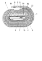
図1は、本発明の第1の実施の形態における、密閉型二次電池に用いられる捲回体の構成の例を断面図として示したものである。図1において、正極集電体2の両面にはその最外周部および最内周部を除いて正極合剤層3,4がそれぞれ形成されており、これら正極集電体2および正極合剤層3,4は合わせて正極電極体を構成している。一方、負極集電体5の両面にはその最内周部を除いて負極合剤層6,7がそれぞれ形成されており、これら負極集電体5および負極合剤層6,7は合わせて負極電極体を構成している。正極電極体と負極電極体は絶縁性のシートである2枚のセパレータ8を間に挟んで積層されており、正極電極体、負極電極体および2枚のセパレータ8は互いに捲回されて捲回体を構成している。図1に示した捲回体を密閉型二次電池として用いる際には、金属製の缶である外装体の内部にこの捲回体を挿入し、電解質溶液を捲回体に含浸させて外装体を密封して用いることになる。
FIG. 1 is a cross-sectional view showing an example of the configuration of a wound body used in a sealed secondary battery according to the first embodiment of the present invention. In FIG. 1, positive
図1において、2枚のセパレータ8は、正極合剤層3と負極合剤層6、正極合剤層4と負極合剤層7の互いに対向する面の間にそれぞれ配置されて両側の合剤層どうしを電気的に絶縁しており、このため正極電極体と負極電極体は捲回体の内部で互いに接することはない。捲回体の最外周部に位置する領域では、正極集電体2の内側面に正極合剤層3が設けられているものの、外側面には正極合剤層4が設けられずに片面塗布部となっており、この領域に金属箔1が配置されている。また正極集電体2の内側面に設けられた正極合剤層3はその先端部と途中に2箇所の合剤層のない未塗工部を有しており、また正極集電体2の最内周部に位置する端部領域にも未塗工部が設けられている。
In FIG. 1, two
捲回体の最外周部の正極集電体2の外側面に設けられた金属箔1は、前記2箇所の未塗工部を跨ぐように配置されており、この2箇所の未塗工部にて正極集電体2にそれぞれ接合固定されている。この2箇所の未塗工部の間には正極合剤層3が片面のみに設けられた領域が存在するが、この領域では金属箔1は正極集電体2に接合されていない。なお正極集電体2の最端部の未塗工部には密閉型二次電池の外装体の正極端子に電気的に接続される正極リード9が配置されており、金属箔1および正極リード9は正極集電体2の両面にそれぞれ一体に接合固定されている。一方、捲回体の最内周部では負極合剤層6,7が設けられていない負極集電体5の端部領域に負極リード10が接合固定されており、この負極リード10は密閉型二次電池の外装体の負極端子に電気的に接続されるものである。
The
なお図1に示した捲回体の構成の例では、2枚のセパレータ8が捲回体の最内周部で互いに繋がって折り曲げられた1枚のシートを構成しているが、1枚のシートの代わりに2枚の独立したシートを用いてセパレータ8を構成しても構わない。これらの正極電極体と負極電極体、およびセパレータ8を互いに重ね合わせ、捲回することにより図1に示した捲回体が形成される。図1では捲回体の捲き回しがその途中で省略されているが、実際の捲回体では数〜数十回程度の捲回しが行われている。この捲回体が図1の上下方向に圧迫されて扁平形状となっているのは薄型の密閉型二次電池を構成するためであり、円筒形状の密閉型二次電池の場合には各構成部材を円柱状に捲回した形状とすればよい。この捲回体には電解質溶液が含浸されるが、この電解質溶液はセパレータ8を自由に透過できることが必要である。このためセパレータ8としては絶縁性の多孔質樹脂のシートの使用が好適である。また図1では捲回体の最外周部に正極電極体を配置した場合の例を示しているが、捲回体の最外周部に負極電極体を配置した場合であっても同様の構成となる。
In the example of the configuration of the wound body shown in FIG. 1, the two
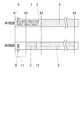
図2は、図1に示した本発明の第1の実施の形態における、密閉型二次電池に用いられる捲回する前の正極電極体の例を平面図として示したものである。図2では正極電極体の外側面および内側面の両面をそれぞれ個別に示しており、図2の上側が図1の捲回体の外周部側(外側面)、図2の下側が内周部側(内側面)に対応している。また図2のX1〜X4の記号の位置は、図1に示した捲回体における同じ記号の位置にそれぞれ対応している。図2の正極電極体の外側面において、最端部であるX1からX3の間(X1−X3間)の全領域は、正極集電体2の面上に正極合剤層4が設けられない片面塗布部となっており、そこに金属箔1が配置されている。
FIG. 2 is a plan view showing an example of the positive electrode body before winding used in the sealed secondary battery in the first embodiment of the present invention shown in FIG. In FIG. 2, both the outer side surface and the inner side surface of the positive electrode body are individually shown. The upper side of FIG. 2 is the outer peripheral side (outer side surface) of the wound body of FIG. 1, and the lower side of FIG. It corresponds to the side (inner side). Further, the positions of the symbols X1 to X4 in FIG. 2 respectively correspond to the positions of the same symbols in the wound body shown in FIG. In the outer surface of the positive electrode body in FIG. 2, the positive
一方、図2の正極電極体の内側面では、X1−X2間の全部およびX2−X3間の一部の領域は正極合剤層3が存在しない未塗工部11,12となっており、金属箔1はこれらの未塗工部11,12で電気伝導性を有する接合方法により正極集電体2に接合固定されている。正極電極体の内側面の最端部の近傍には正極リード9が配置されていて、正極集電体2に対して未塗工部11において外側面の金属箔1とともに一括して接続されている。金属箔1および正極リード9は正極集電体2への電気伝導性を維持したまま接合される必要があり、その接合方法としては、レーザ溶接、抵抗溶接などの溶接、熱圧着、超音波接合などの圧着、導電性接着剤による接着の各方法が適している。X3−X4間の領域は、正極電極体の内側面および外側面の両面にそれぞれ正極合剤層3,4が形成されており、正極集電体2に対する両面塗布部となっている。図2のX4より右側の領域は捲回体の最内周部となる領域であり、短い未塗工部の領域が設けられている。
On the other hand, on the inner surface of the positive electrode body in FIG. 2, the entire region between X1 and X2 and the partial region between X2 and X3 are
図3は、図2に示した本発明の第1の実施の形態における、捲回する前の正極電極体の例について、外周部側の最端部の領域の断面図を示したものである。図3に示した正極集電体2の上側が正極集電体の外側面であり、下側が内側面である。図3の正極集電体2の上側には金属箔1が、下側には正極リード9が配置されており、金属箔1と正極リード9は正極集電体2を挟んで正極電極体の長さ方向に対して同一の位置で接合されている。この場合は三者の接合を一括して行うことが適しており、溶接、圧着、導電性接着剤による接着のいずれの方法でも三者を一括して同時に接合することが可能である。
FIG. 3 is a cross-sectional view of the outermost region on the outer peripheral side in the example of the positive electrode body before winding in the first embodiment of the present invention shown in FIG. . The upper side of the positive electrode
また図4は図1に示した捲回体を挿入し、封止して密閉型二次電池とするための容器の外観を示す概略図である。図1に示した捲回体の例が扁平形状である理由は、図4に示したような、薄型の四角形状である角形の外装体16を有する密閉型二次電池に用いることを想定したためである。外装体16には外部負極端子である負極ピン13と、安全弁14、封口部15が設けられており、図4の例では外装体16の表面が外部正極端子となっている。ここで、外装体16に挿入される捲回体の最外周部に正極電極体と負極電極体のどちらが配置されるかは、外装体16の材質によって決定される。外装体16として例えばアルミニウム缶を用いた場合は、このアルミニウム缶が正極となるため、外装体16の内面と電池要素である捲回体の最外周部が接触しても問題がないように、捲回体の最外周部には正極電極体を配置することとなる。逆に、外装体16として例えば鉄系の材料を用いた場合は、捲回体の最外周部には負極電極体を配置する必要がある。
FIG. 4 is a schematic view showing the outer appearance of a container for inserting the sealed body shown in FIG. 1 and sealing it to form a sealed secondary battery. The reason why the wound body shown in FIG. 1 has a flat shape is that it is assumed that the wound body is used for a sealed secondary battery having a rectangular
さらに図5は、本発明の第2の実施の形態における密閉型二次電池に用いられる捲回体の構成の例を断面図として示したものである。この本発明の第2の実施の形態では、捲回体を構成する各電極体として、正極集電体2および負極集電体5のそれぞれ片面にのみ、正極合剤層3と負極合剤層6を形成している。この捲回体はこれらの電極体をセパレータ8を介して積層し、捲回したものであるため、本発明の第2の実施の形態での2枚のセパレータ8のうち1枚は正極および負極の各電極体の集電体面どうし、もう1枚は合剤層の表面どうしをそれぞれ隔てる構成となっている。これ以外の構成は、金属箔1、正極リード9および負極リード10の構成も含めて図1に示した本発明の第1の実施の形態の捲回体の構成の例の場合と同様である。
FIG. 5 is a cross-sectional view showing an example of the configuration of the wound body used in the sealed secondary battery according to the second embodiment of the present invention. In the second embodiment of the present invention, as each electrode body constituting the wound body, the positive
本発明における密閉型二次電池では、前記のように正極集電体にはアルミニウム、アルミニウム合金、チタンなどの導電体箔が好適に用いられる。ここで正極合剤層に用いられる正極活物質としては、LiCoO2、LiNiO2、LiMn2O4などの金属酸化物が好ましく、他には負極電極体との電位差が1V以上得られる物質である、V2O5、MnO2、MoS2、TiS2、もしくはこれらの各物質の混合物を用いることができる。これらの正極活物質の粉末に、ポリフッ化ビニリデンなどのポリビニリデンフルオドライド、ポリテトラフルオロエチレン、ポリエチレンなどの結着剤を加えて混合し、これを正極集電体に塗布し、乾燥することで正極合剤層を形成して正極電極体とすることができる。 In the sealed secondary battery according to the present invention, as described above, the positive electrode current collector is preferably made of a conductive foil such as aluminum, aluminum alloy, or titanium. Here, as the positive electrode active material used for the positive electrode mixture layer, metal oxides such as LiCoO 2 , LiNiO 2 , and LiMn 2 O 4 are preferable, and other materials that can obtain a potential difference of 1 V or more from the negative electrode body. V 2 O 5 , MnO 2 , MoS 2 , TiS 2 , or a mixture of these substances can be used. By adding a binder such as polyvinylidene fluoride such as polyvinylidene fluoride, polytetrafluoroethylene, polyethylene, etc. to these positive electrode active material powders, mixing this, applying it to the positive electrode current collector, and drying. A positive electrode mixture layer can be formed to form a positive electrode body.
また前記のように負極集電体には銅、ニッケル、ステンレス、銀などの導電体箔が好適に用いられる。ここで負極合剤層に用いられる負極活物質としては、炭素質材料である天然黒鉛や人造黒鉛が好ましい。このような黒鉛類からなる負極活物質の粉末に、同じくポリフッ化ビニリデンなどのポリビニリデンフルオドライド、ポリエチレン、スチレンブタジエンなどの結着剤を加えて混合し、これを負極集電体に塗布し、乾燥することで負極合剤層を形成して負極電極体とすることができる。 Further, as described above, a conductor foil such as copper, nickel, stainless steel, or silver is preferably used for the negative electrode current collector. Here, as the negative electrode active material used for the negative electrode mixture layer, natural graphite or artificial graphite which is a carbonaceous material is preferable. To the powder of the negative electrode active material made of graphite, a binder such as polyvinylidene fluoride such as polyvinylidene fluoride, polyethylene, styrene butadiene is added and mixed, and this is applied to the negative electrode current collector. By drying, a negative electrode mixture layer can be formed into a negative electrode body.
さらに正極電極体と負極電極体とを絶縁するセパレータは、両者の短絡を防ぐとともにイオン導電性を有し、電解質溶液が透過できるフィルム状のものであればどのような材質でも構わない。一般にはセパレータとしては多孔性を有するポリオレフィンフィルムを用いることが好ましく、その材質としてポリエチレンオキサイド誘導体、ポリスチレン、ポリブタジエンおよびその共重合体、ポリビニリデンフルオライドなどを用いた多孔質フィルムを使用することができる。またセパレータとともに、絶縁層として公知の固体電解質を加えて捲回体を構成してもよい。 Furthermore, the separator that insulates the positive electrode body from the negative electrode body may be made of any material as long as it prevents the short circuit between them and has ionic conductivity and allows the electrolyte solution to pass therethrough. In general, a polyolefin film having porosity is preferably used as the separator, and a porous film using a polyethylene oxide derivative, polystyrene, polybutadiene and a copolymer thereof, polyvinylidene fluoride, or the like can be used as the material. . Moreover, you may comprise a winding body by adding a well-known solid electrolyte as an insulating layer with a separator.
なお、電池として機能させるためには、作製した捲回体に電解質溶液を含浸させる必要がある。この電解質溶液としては、各種塩類を有機溶媒に溶解させた非水有機電解質溶液を用いることができる。添加する塩類としては、LiClO4、LiBF4、LiPF6、LiAsF6など、およびこれら塩類の1種または2種以上の混合物を適用可能である。一方有機溶媒としては、エチレンカーボネート、プロピレンカーボネート、ジメチルカーボネート、γ−ブチルラクトン、1,2−ジメトキシエタン、テトロヒドロフランなど、およびこれらの有機溶媒の1種または2種を以上の混合物を用いることができる。 In order to function as a battery, it is necessary to impregnate the manufactured wound body with an electrolyte solution. As this electrolyte solution, a non-aqueous organic electrolyte solution in which various salts are dissolved in an organic solvent can be used. As salts to be added, LiClO 4 , LiBF 4 , LiPF 6 , LiAsF 6 and the like, and one or a mixture of two or more of these salts are applicable. On the other hand, as an organic solvent, ethylene carbonate, propylene carbonate, dimethyl carbonate, γ-butyl lactone, 1,2-dimethoxyethane, tetrohydrofuran, etc., and a mixture of one or more of these organic solvents should be used. Can do.
また、本発明に係る密閉型二次電池においては、捲回体を封止する外装体である電池缶、前記電池缶の蓋、安全弁などの安全装置、正極もしくは負極の外部端子などの詳述していない各種の構成材料として、既存の部材や今後の開発品を使用することができる。 Further, in the sealed secondary battery according to the present invention, a battery can which is an outer package for sealing the wound body, a safety device such as a lid of the battery can, a safety valve, an external terminal of the positive electrode or the negative electrode, etc. Existing components and future developed products can be used as various constituent materials that are not used.
以下、本発明を実施例に基づいて具体的に説明する。 Hereinafter, the present invention will be specifically described based on examples.
(実施例1)
正極活物質としてLiCoO2を94重量部用意し、それに結着剤としてポリフッ化ビニリデンを3重量部、導電材としてアセチレンブラックを3重量部、溶媒としてN−メチル−2−ピロリドンを50重量部用意して、これらを混合してスラリーとした。次いでこのスラリーを厚さ15μmの細長いアルミニウム箔からなる正極集電体の両面に塗布し、乾燥、圧延を実施して、正極合剤層を形成して正極電極体とした。この際に、捲回体の最外周部となる正極集電体の一方の端部には、図1および図2に示される所定の片面塗布部および未塗工部を設けている。その後作製した正極電極体を裁断し、形状を整えた。
Example 1
94 parts by weight of LiCoO 2 as a positive electrode active material, 3 parts by weight of polyvinylidene fluoride as a binder, 3 parts by weight of acetylene black as a conductive material, and 50 parts by weight of N-methyl-2-pyrrolidone as a solvent These were mixed into a slurry. Next, this slurry was applied to both surfaces of a positive electrode current collector made of an elongated aluminum foil having a thickness of 15 μm, dried and rolled to form a positive electrode mixture layer to obtain a positive electrode body. At this time, a predetermined single-side coated portion and an uncoated portion shown in FIGS. 1 and 2 are provided at one end of the positive electrode current collector that is the outermost peripheral portion of the wound body. Thereafter, the produced positive electrode body was cut and shaped.
一方、負極活物質として鱗片状黒鉛を97重量部用意し、それに結着剤としてポリフッ化ビニリデンを3重量部、溶媒としてN−メチル−2−ピロリドンを60重量部用意して、これらを混合してスラリーとした。次いでこのスラリーを、厚さ10μmの細長い銅箔からなる負極集電体の両面に塗布し、乾燥、圧延を実施して、負極合剤層を形成して負極電極体とした。この際に、捲回体の最内周部となる負極集電体の一方の端部には、図1に示される所定の片面塗布部および未塗工部を設けている。その後作製した負極電極体を同様に裁断し、形状を整えた。 On the other hand, 97 parts by weight of scaly graphite as a negative electrode active material, 3 parts by weight of polyvinylidene fluoride as a binder, and 60 parts by weight of N-methyl-2-pyrrolidone as a solvent are prepared and mixed. To make a slurry. Next, this slurry was applied to both surfaces of a negative electrode current collector made of a thin copper foil having a thickness of 10 μm, dried and rolled to form a negative electrode mixture layer to obtain a negative electrode body. At this time, a predetermined single-side coated portion and an uncoated portion shown in FIG. 1 are provided at one end of the negative electrode current collector that is the innermost peripheral portion of the wound body. Thereafter, the produced negative electrode body was cut in the same manner to prepare the shape.
正極電極体の最外周部は、捲回体とした際に外側となる側の集電体の面上に正極合剤層を形成せずに、内側面のみに正極合剤層を設けた片面塗布部としている。この片面塗布部に金属箔としてアルミニウム箔を配置し、正極集電体に対して超音波溶接によって接合した。この際の接合領域は、正極集電体の片面塗布部のうち未塗工部である図2の未塗工部11,12の2箇所の領域のみである。このうち未塗工部11では金属箔の接合面とは反対側(裏側)の面に、正極リードを金属箔と個別に接合させている。また負極電極体の最内周部の未塗工部の領域には、同じく超音波溶接によって負極リードを接合させた。これ以外の集電体の片面に正極合剤層のある片面塗布部には溶接領域が設けられておらず、金属箔はこの領域で正極集電体の片面に接触しているだけで、固定されていない。
The outermost peripheral portion of the positive electrode body is a single-sided surface in which the positive electrode mixture layer is provided only on the inner surface without forming the positive electrode mixture layer on the surface of the current collector on the outer side when the wound body is formed. The application part. An aluminum foil was placed as a metal foil on this single-side coated part and joined to the positive electrode current collector by ultrasonic welding. The joining area | region in this case is only 2 area | regions of the
次いで正極電極体、セパレータ、負極電極体、セパレータをこの順に重ねて積層体とした。積層体の寸法は、外周側となる正極電極体が幅20mm、長さ400mmであり、セパレータおよび負極電極体はこれより長さが若干短くなっている。この積層体を長さ方向に20回捲回して捲回体を作製した。この際に、正極集電体の最外周部に接合した金属箔を捲回体に1周以上捲回し、捲回した金属箔の巻き始め側に近い端部の一部が、金属箔の巻き終わり側に近い端部の先端領域に、セパレータや正極電極体、負極電極体を挟んで外側から被覆されるように配置した。なお2枚のセパレータはその最内周部にて繋がっており、1枚のセパレータをその長さ方向の中央で折り曲げ、負極電極体を両側から挟み込んだ形状となっている。 Next, a positive electrode body, a separator, a negative electrode body, and a separator were stacked in this order to form a laminate. Regarding the dimensions of the laminate, the positive electrode body on the outer peripheral side is 20 mm wide and 400 mm long, and the separator and the negative electrode body are slightly shorter in length. This laminate was wound 20 times in the length direction to produce a wound body. At this time, the metal foil bonded to the outermost peripheral portion of the positive electrode current collector is wound around the wound body one or more times, and a part of the end portion near the winding start side of the wound metal foil is wound around the metal foil. The tip region near the end side was disposed so as to be covered from the outside with the separator, the positive electrode body, and the negative electrode body interposed therebetween. Note that the two separators are connected at the innermost peripheral portion, and one separator is bent at the center in the length direction, and the negative electrode body is sandwiched from both sides.
作製した捲回体を側面方向に圧迫し、扁平形状としてから図4に示す角型の密閉型二次電池用の容器に封入した。容器の形状は外形で厚さが10mm、幅が20mm、高さが25mmである。ここで密閉型二次電池の容器である外装体はアルミニウム製の缶であり、外装体の上部に負極ピンと安全弁、封口部が設けられている。外装体には正極リードを、銅製の負極ピンには負極リードを溶接してそれぞれ外部端子とし、封口部から電解質溶液としてLiClO4を添加したエチレンカーボネート溶液(非水有機電解質溶液)を充填して捲回体に含浸させ、封口部を封止して密閉型二次電池とした。この密閉型二次電池を計300個作製し、実施例1とした。 The produced wound body was pressed in the lateral direction to form a flat shape, and then sealed in a rectangular sealed secondary battery container shown in FIG. The container has an outer shape with a thickness of 10 mm, a width of 20 mm, and a height of 25 mm. Here, the outer package, which is a container for the sealed secondary battery, is an aluminum can, and a negative electrode pin, a safety valve, and a sealing portion are provided on the upper portion of the outer package. The outer body is welded with a positive electrode lead, and the negative electrode lead made of copper is welded with the negative electrode lead to form an external terminal, and an ethylene carbonate solution (nonaqueous organic electrolyte solution) to which LiClO 4 is added as an electrolyte solution is filled from the sealing portion The wound body was impregnated and the sealing portion was sealed to obtain a sealed secondary battery. A total of 300 of these sealed secondary batteries were produced and designated as Example 1.
これら実施例1の300個の密閉型二次電池に対してまず内部抵抗をそれぞれ測定し、各電池の内部抵抗の値が規定された基準値以下であることを確認した。次いでこれら全部の密閉型二次電池に対して充放電サイクル試験と落下試験をそれぞれ行った。まず充放電サイクル試験としては、45℃の試験雰囲気にて、正極活物質の塗工量から算出した電池容量を基準として、1Cレート(電池の全容量を1時間で放電させる電流量)および4.2Vの定電流定電圧の条件(当初は1Cレートの定電流充電を行い、端子電圧が4.2Vに達したら定電圧充電に移行する条件)で3時間の充電を行い、次いで1Cレートの放電電流にて端子電圧が3.0Vとなるまでの放電を行った。この1サイクルの充放電を、試験雰囲気を保ったままで10サイクル繰り返した。 First, the internal resistance of each of the 300 sealed secondary batteries of Example 1 was measured, and it was confirmed that the value of the internal resistance of each battery was not more than a prescribed reference value. Next, a charge / discharge cycle test and a drop test were performed on all of these sealed secondary batteries. First, as a charge / discharge cycle test, in a test atmosphere of 45 ° C., a 1C rate (amount of current that discharges the entire capacity of the battery in 1 hour) and 4 based on the battery capacity calculated from the coating amount of the positive electrode active material. Charge for 3 hours under the condition of constant current and constant voltage of 2V (initially constant current charge at 1C rate, and shift to constant voltage charge when the terminal voltage reaches 4.2V), then 1C rate Discharge was performed until the terminal voltage reached 3.0 V with the discharge current. This one-cycle charging / discharging was repeated 10 cycles while maintaining the test atmosphere.
次に前記の充放電サイクル試験を実施した各々の電池について、1Cレートおよび4.2Vの定電流定電圧の条件で3時間の充電を行い、充電後の電池を1.2mの高さからコンクリート面に落下させる落下試験を連続して5サイクル実施した。この落下試験では、角型の密閉型二次電池の側面の広い2面をそれぞれ下に向けて1回ずつ落下させ、計2回の落下を行ってこれを1サイクルとしている。従って5サイクルの落下試験で各電池は落下の衝撃を10回ずつ与えられている。この10サイクルの充放電サイクル試験と5サイクルの落下試験をセットとして各電池に対して50回(合計で充放電サイクル試験500サイクル、落下試験500回)繰り返した。なお50回の充放電サイクル試験と落下試験の繰り返しは、密閉型二次電池の一般的な使用で想定される外部衝撃の頻度を考えると相当に過酷なものである。この過酷な試験は、密閉型二次電池に生じる電極体の破断の発生状況を詳しく解析する目的で不良発生率をあえて高めるために実施したものであり、密閉型二次電池の一般的な使用でこの場合のような高い不良率が生じることはない。
Next, each of the batteries subjected to the above charge / discharge cycle test was charged for 3 hours under the conditions of a 1C rate and a constant current / constant voltage of 4.2 V. A drop test for dropping onto the surface was continuously performed for 5 cycles. In this drop test, two wide surfaces of the rectangular sealed secondary battery are dropped downwards one by one, and a total of two drops is made as one cycle. Therefore, in the 5-cycle drop test, each battery is given a
一連の試験の終了後にまず密閉型二次電池の内部抵抗を測定し、各電池の内部抵抗の値が規定された基準値を上回っているかどうかを調査した。次いで全ての電池を分解して、正極電極体の片面塗布部に破断が発生しているかどうかを目視にて調査した。表1に、実施例1の300個の密閉型二次電池における、これら一連の試験の後での片面塗布部における正極電極体の破断発生率(%)、破断未発生品の抵抗不良率(%)(試験後に内部抵抗が基準値を上回った個数の割合)、破断発生品の抵抗不良率(%)、および全試料の抵抗不良率(%)の値をそれぞれ記す。 After the end of a series of tests, first, the internal resistance of the sealed secondary battery was measured, and it was investigated whether or not the value of the internal resistance of each battery exceeded a prescribed reference value. Subsequently, all the batteries were disassembled, and it was visually inspected whether or not a break occurred in the one-side coated portion of the positive electrode body. Table 1 shows the rupture rate (%) of the positive electrode body in the single-side coated part after these series of tests in 300 sealed secondary batteries of Example 1, and the resistance failure rate of the non-ruptured product ( %) (The ratio of the number of the internal resistance exceeding the reference value after the test), the resistance failure rate (%) of the product with breakage, and the resistance failure rate (%) of all the samples.
(実施例2)
実施例1の場合と同様に計300個の密閉型二次電池を作製し、実施例2とした。実施例1の場合との違いは、正極電極体の未塗工部への金属箔と正極リードの接合方法のみである。実施例2では、正極集電体の両側に金属箔と正極リードとを個別ではなく、一括して同時に超音波溶接により接合している。それ以外の条件である、これら300個の密閉型二次電池に対する内部抵抗の測定時期、充放電サイクル試験および落下試験の実施方法や回数は、実施例1の場合と同一である。表1に、実施例2の300個の密閉型二次電池の片面塗布部における正極電極体の破断発生率(%)、破断未発生品の抵抗不良率(%)、破断発生品の抵抗不良率(%)、および全試料の抵抗不良率(%)の値をそれぞれ記す。
(Example 2)
A total of 300 sealed secondary batteries were produced in the same manner as in Example 1, and designated as Example 2. The only difference from Example 1 is the method of joining the metal foil and the positive electrode lead to the uncoated part of the positive electrode body. In Example 2, the metal foil and the positive electrode lead are joined to both sides of the positive electrode current collector by ultrasonic welding at the same time, not individually. The other conditions, the measurement time of internal resistance for these 300 sealed secondary batteries, the charge / discharge cycle test, and the execution method and frequency of the drop test are the same as in the first embodiment. Table 1 shows the rate of occurrence of rupture (%) of the positive electrode body in the single-side coated part of 300 sealed secondary batteries of Example 2, the rate of defective resistance (%) of the unbreaked product, and the poor resistance of the ruptured product. Percentage (%) and resistance failure rate (%) values of all samples are described.
(実施例3)
実施例1の場合と同様に計300個の密閉型二次電池を作製し、実施例3とした。実施例1の場合との違いは、正極電極体および負極電極体への正極および負極リード、金属箔の接合方法のみである。実施例3ではこれらの接合のために、超音波溶接ではなく熱圧着を行った。それ以外の条件である、これら300個の密閉型二次電池に対する内部抵抗の測定時期、充放電サイクル試験および落下試験の実施方法や回数は、実施例1の場合と同一である。表1に、実施例3の300個の密閉型二次電池の片面塗布部における正極電極体の破断発生率(%)、破断未発生品の抵抗不良率(%)、破断発生品の抵抗不良率(%)、および全試料の抵抗不良率(%)の値をそれぞれ記す。
(Example 3)
A total of 300 sealed secondary batteries were produced in the same manner as in Example 1, and designated as Example 3. The difference from the case of Example 1 is only the method of joining the positive electrode and the negative electrode lead and the metal foil to the positive electrode body and the negative electrode body. In Example 3, for these joining, thermocompression bonding was performed instead of ultrasonic welding. The other conditions, the measurement time of internal resistance for these 300 sealed secondary batteries, the charge / discharge cycle test, and the execution method and frequency of the drop test are the same as in the first embodiment. Table 1 shows the rate of occurrence of breakage (%) of the positive electrode body in the single-side coated part of 300 sealed secondary batteries of Example 3, the failure rate (%) of non-ruptured products, and the resistance failure of broken products. Percentage (%) and resistance failure rate (%) values of all samples are described.
(実施例4)
実施例1の場合と同様に計300個の密閉型二次電池を作製し、実施例4とした。実施例1の場合との違いは、正極電極体および負極電極体への正極および負極リード、金属箔の接合方法のみである。実施例4ではこれらの接合のために、超音波溶接ではなくエポキシ系の導電性接着剤による接着を行った。それ以外の条件である、これら300個の密閉型二次電池に対する内部抵抗の測定時期、充放電サイクル試験および落下試験の実施方法や回数は実施例1の場合と同一である。表1に、実施例4の300個の密閉型二次電池の片面塗布部における正極電極体の破断発生率(%)、破断未発生品の抵抗不良率(%)、破断発生品の抵抗不良率(%)、および全試料の抵抗不良率(%)の値をそれぞれ記す。
Example 4
A total of 300 sealed secondary batteries were produced in the same manner as in Example 1, and designated as Example 4. The difference from the case of Example 1 is only the method of joining the positive electrode and the negative electrode lead and the metal foil to the positive electrode body and the negative electrode body. In Example 4, for these joining, adhesion by an epoxy-based conductive adhesive was performed instead of ultrasonic welding. The other conditions, the measurement time of the internal resistance for these 300 sealed secondary batteries, the charge / discharge cycle test, and the method and number of executions of the drop test are the same as in the first embodiment. Table 1 shows the occurrence rate of fracture (%) of the positive electrode body in the single-side coated part of 300 sealed secondary batteries of Example 4, the resistance failure rate (%) of the unbreaked product, and the resistance failure of the broken product. Percentage (%) and resistance failure rate (%) values of all samples are described.
(実施例5)
実施例1の場合と同様に計300個の密閉型二次電池を作製し、実施例5とした。実施例1の場合との違いは、正極集電体および負極集電体の表面への正極および負極合剤層の形成を、その両面ではなく片面のみにそれぞれ行っていることのみである。実施例5の密閉型二次電池は、図5に示した本発明の第2の実施の形態の場合に該当する。それ以外の条件である、これら300個の密閉型二次電池に対する内部抵抗の測定時期、充放電サイクル試験および落下試験の実施方法や回数は実施例1の場合と同一である。表1に、実施例5の300個の密閉型二次電池の片面塗布部における正極電極体の破断発生率(%)、破断未発生品の抵抗不良率(%)、破断発生品の抵抗不良率(%)、および全試料の抵抗不良率(%)の値をそれぞれ記す。
(Example 5)
A total of 300 sealed secondary batteries were produced in the same manner as in Example 1, and designated as Example 5. The only difference from the case of Example 1 is that the formation of the positive electrode and negative electrode mixture layers on the surfaces of the positive electrode current collector and the negative electrode current collector is performed only on one side, not on both sides. The sealed secondary battery of Example 5 corresponds to the case of the second embodiment of the present invention shown in FIG. The other conditions, the measurement time of the internal resistance for these 300 sealed secondary batteries, the charge / discharge cycle test, and the method and number of executions of the drop test are the same as in the first embodiment. Table 1 shows the rate of occurrence of breakage (%) of the positive electrode body in the single-side coated part of 300 sealed secondary batteries of Example 5, the failure rate (%) of non-ruptured products, and the resistance failure of broken products. Percentage (%) and resistance failure rate (%) values of all samples are described.
(実施例6)
実施例1の場合と同様に計300個の密閉型二次電池を作製し、実施例6とした。実施例1の場合との違いは、正極電極体および負極電極体の構成を逆として、外側領域の方に負極電極体が位置するように捲回体を構成したことである。金属箔としては銅箔を用い、密閉型二次電池の外装体は鉄製として、外装体に設けられる負極ピンの代わりに正極ピンを設けた。この場合は外装体が負極、正極ピンが正極となっており、実施例1の密閉型二次電池の場合と外部の電極の正負が逆となっている。なおそれ以外の条件である、これら300個の密閉型二次電池に対する内部抵抗の測定時期、充放電サイクル試験および落下試験の実施方法や回数は実施例1の場合と同一である。表1に、実施例6の300個の密閉型二次電池の片面塗布部における負極電極体の破断発生率(%)、破断未発生品の抵抗不良率(%)、破断発生品の抵抗不良率(%)、および全試料の抵抗不良率(%)の値をそれぞれ記す。
(Example 6)
A total of 300 sealed secondary batteries were produced in the same manner as in Example 1, and designated as Example 6. The difference from the case of Example 1 is that the configuration of the positive electrode body and the negative electrode body is reversed, and the wound body is configured so that the negative electrode body is located in the outer region. Copper foil was used as the metal foil, the outer package of the sealed secondary battery was made of iron, and a positive electrode pin was provided instead of the negative electrode pin provided on the outer package. In this case, the outer package is a negative electrode, and the positive electrode pin is a positive electrode, and the positive and negative of the external electrode is opposite to the case of the sealed secondary battery of Example 1. In addition, the measurement conditions of the internal resistance for these 300 sealed secondary batteries, the charge / discharge cycle test, and the execution method and the number of drop tests, which are other conditions, are the same as those in the first embodiment. Table 1 shows the breakage rate (%) of the negative electrode body in the single-side coated part of 300 sealed secondary batteries of Example 6, the resistance failure rate (%) of the product without breakage, and the resistance failure of the product with breakage. Percentage (%) and resistance failure rate (%) values of all samples are described.
(比較例1)
実施例1の場合と同様に計300個の密閉型二次電池を作製し、比較例1とした。比較例1では正極電極体に金属箔を設けておらず、正極電極体および負極電極体には正極リードと負極リードのみがそれぞれ超音波溶接されている。それ以外の条件である、これら300個の密閉型二次電池に対する内部抵抗の測定時期、充放電サイクル試験および落下試験の実施方法や回数は実施例1の場合と同一である。表1に、比較例1の300個の密閉型二次電池の片面塗布部における正極電極体の破断発生率(%)、破断未発生品の抵抗不良率(%)、破断発生品の抵抗不良率(%)、および全試料の抵抗不良率(%)の値をそれぞれ記す。
(Comparative Example 1)
A total of 300 sealed secondary batteries were produced in the same manner as in Example 1, and used as Comparative Example 1. In Comparative Example 1, no metal foil is provided on the positive electrode body, and only the positive electrode lead and the negative electrode lead are ultrasonically welded to the positive electrode body and the negative electrode body, respectively. The other conditions, the measurement time of the internal resistance for these 300 sealed secondary batteries, the charge / discharge cycle test, and the method and number of executions of the drop test are the same as in the first embodiment. Table 1 shows the rate of occurrence of breakage (%) of the positive electrode body in the single-side coated part of the 300 sealed secondary batteries of Comparative Example 1, the rate of defective resistance (%) of the unbreakable product, and the poor resistance of the broken product Percentage (%) and resistance failure rate (%) values of all samples are described.
(比較例2)
実施例1の場合と同様に計300個の密閉型二次電池を作製し、比較例2とした。比較例2では比較例1とは異なり、正極電極体に金属箔に相当する電極体の補強部材を設けてはいるが、その構成材料が実施例1の場合とは異なっている。比較例2における電極体の補強部材はポリエステルフィルムであり、実施例1の金属箔と同一形状で、正極集電体の2箇所の未塗工部にエポキシ系接着剤により接合されている。なお未塗工部への接着領域の範囲は実施例1の場合と同様である。それ以外の条件である、これら300個の密閉型二次電池に対する内部抵抗の測定時期、充放電サイクル試験および落下試験の実施方法や回数は実施例1の場合と同一である。表1に、比較例2の300個の密閉型二次電池の片面塗布部における正極電極体の破断発生率(%)、破断未発生品の抵抗不良率(%)、破断発生品の抵抗不良率(%)、および全試料の抵抗不良率(%)の値をそれぞれ記す。
(Comparative Example 2)
A total of 300 sealed secondary batteries were produced in the same manner as in Example 1 and used as Comparative Example 2. Unlike Comparative Example 1, Comparative Example 2 is provided with a reinforcing member for an electrode body corresponding to a metal foil on the positive electrode body, but its constituent material is different from that of Example 1. The reinforcing member of the electrode body in Comparative Example 2 is a polyester film, which has the same shape as the metal foil of Example 1, and is joined to two uncoated parts of the positive electrode current collector by an epoxy adhesive. In addition, the range of the adhesion area | region to an uncoated part is the same as that of the case of Example 1. The other conditions, the measurement time of the internal resistance for these 300 sealed secondary batteries, the charge / discharge cycle test, and the method and number of executions of the drop test are the same as in the first embodiment. Table 1 shows the rate of occurrence of breakage (%) of the positive electrode body in the single-side coated part of 300 sealed secondary batteries of Comparative Example 2, the rate of defective resistance (%) of the unbreakable product, and the poor resistance of the broken product. Percentage (%) and resistance failure rate (%) values of all samples are described.
(比較例3)
実施例4の場合と同様に計300個の密閉型二次電池を作製し、比較例3とした。比較例3では比較例2の場合とは異なり、正極電極体には金属箔からなる電極体の補強部材を設けており、その金属箔の形状や素材(アルミニウム)は実施例4の場合と同一である。実施例4の場合との違いは正極集電体への金属箔の接合方法であり、金属箔の一部のみではなく、片側全面にエポキシ系の導電性接着剤を塗布して正極集電体の片面塗布部に貼付固定することで接合している。それ以外の条件である、これら300個の密閉型二次電池に対する内部抵抗の測定時期、充放電サイクル試験および落下試験の実施方法や回数は実施例4の場合と同一である。表1に、比較例3の300個の密閉型二次電池の片面塗布部における正極電極体の破断発生率(%)、破断未発生品の抵抗不良率(%)、破断発生品の抵抗不良率(%)、および全試料の抵抗不良率(%)の値をそれぞれ記す。
(Comparative Example 3)
A total of 300 sealed secondary batteries were produced in the same manner as in Example 4 and used as Comparative Example 3. In Comparative Example 3, unlike the case of Comparative Example 2, the positive electrode body is provided with an electrode body reinforcing member made of a metal foil, and the shape and material (aluminum) of the metal foil are the same as those in Example 4. It is. The difference from the case of Example 4 is the method of joining the metal foil to the positive electrode current collector, and the positive electrode current collector is obtained by applying an epoxy-based conductive adhesive not only to a part of the metal foil but also to the entire surface of one side. It is joined by attaching and fixing to the single-side application part. The other conditions, the measurement time of the internal resistance for these 300 sealed secondary batteries, the charge / discharge cycle test, and the method and number of executions of the drop test are the same as in Example 4. Table 1 shows the rate of occurrence of rupture of the positive electrode body (%) in the single-side coated portion of 300 sealed secondary batteries of Comparative Example 3, the percentage of defective resistance of the non-ruptured product, and the poor resistance of the ruptured product. Percentage (%) and resistance failure rate (%) values of all samples are described.

表1の電極体の片面塗布部での電極体の破断発生率を比較すると、電極体最外周部に補強部材を全く設けていない比較例1の場合が42.7%であるのに対し、他の実施例1〜6および比較例2〜3では26.7%もしくはそれ以下の相対的に低い値が得られている。従って電極体に対して何らかの補強部材を設けた場合は、その接合方法や材質に関わらず、補強部材を設けない場合に比べて破断発生率が低下する効果が得られることが分かる。また比較例2,3に示した補強部材を全面で電極体最外周部に接合固定した場合は、電極体の破断発生率が、本発明に関する実施例1〜6の場合よりも若干ではあるがむしろ低くなる結果が得られている。従って、本発明の補強部材の固定方法は、電極体の破断発生率のみを単に比較すると、従来技術に比べて必ずしも優れていると言えないことになる。 When comparing the fracture occurrence rate of the electrode body at the single-side coated part of the electrode body of Table 1, the case of Comparative Example 1 in which no reinforcing member is provided at the outermost periphery of the electrode body is 42.7%, In other Examples 1-6 and Comparative Examples 2-3, a relatively low value of 26.7% or less was obtained. Therefore, it can be seen that when any reinforcing member is provided for the electrode body, an effect of lowering the fracture occurrence rate can be obtained compared to the case where the reinforcing member is not provided, regardless of the joining method or material. In addition, when the reinforcing members shown in Comparative Examples 2 and 3 are bonded and fixed to the outermost peripheral portion of the electrode body over the entire surface, the fracture occurrence rate of the electrode body is slightly smaller than those in Examples 1 to 6 related to the present invention. The result is rather low. Therefore, the reinforcing member fixing method of the present invention is not necessarily superior to the prior art when only the fracture occurrence rate of the electrode bodies is simply compared.
しかし、表1の電極体の破断未発生品の抵抗不良率と破断発生品の抵抗不良率とを見れば、本発明の補強部材の固定方法における効果は明瞭である。表1によると、破断未発生品の抵抗不良率では実施例1〜6および比較例1〜3においてさほど差がないものの、破断発生品の抵抗不良率では実施例1〜6が21.9〜24.4%、比較例1〜3が63.4〜65.6%であり、比較例の各々の不良率は実施例の場合に比べていずれも3倍近くに達していることが分かる。このため、破断未発生品と破断発生品を加えた全試料の抵抗不良率においても、表1によると実施例1〜6が21.3〜24.3%、比較例1〜3が32.7〜40.7%であり、本発明の実施例では比較例の場合に比べて全試料の抵抗不良率の改善に関しても有意な効果が得られていることが分かる。 However, the effect of the reinforcing member fixing method according to the present invention is clear from the resistance failure rate of the non-ruptured product of the electrode body and the resistance failure rate of the fractured product in Table 1. According to Table 1, although there is not much difference in the resistance failure rate of the breakage-free products in Examples 1 to 6 and Comparative Examples 1 to 3, Examples 1-6 are 21.9 to 2 24.4% and Comparative Examples 1 to 3 are 63.4 to 65.6%, and it can be seen that the defect rate of each of the Comparative Examples is nearly three times that of the Example. For this reason, also in the resistance failure rate of all the samples which added the breakage-free product and the breakage-occurring product, according to Table 1, Examples 1 to 6 are 21.3 to 24.3%, and Comparative Examples 1 to 3 are 32. It is 7-40.7%, and it can be seen that in the examples of the present invention, a significant effect is obtained in terms of improving the resistance defect rate of all the samples as compared with the comparative example.
以上の結果は次のように解釈することができる。つまり、本発明における補強部材の固定方法では、従来から行われていた補強部材を全面で集電体に固定する方法と比べて、電極体の破断発生率を低下させる効果では必ずしも優れているわけではない。しかしながら密閉型二次電池の電極体に破断が発生した場合には、電池の内部抵抗が増加して抵抗不良となる確率を確実に低下させることができる。表1における実施例1〜6の結果を見ると、いずれも破断未発生品と破断発生品での電池の抵抗不良率は同等程度であり、このことは、本発明の密閉型二次電池において、電極体に破断があるかどうかはその抵抗不良率に殆ど関与していないことを示している。このことから、実施例1〜6における電池の抵抗不良の多くは電極体の破断の有無とは異なる原因によるものと考えられる。従って、本発明の密閉型二次電池では、電極体の破断が生じた場合にも、それによる電池の抵抗不良の発生をほぼ完全に防止できていると考えられる。 The above results can be interpreted as follows. In other words, the reinforcing member fixing method according to the present invention is not necessarily superior in the effect of reducing the fracture occurrence rate of the electrode body as compared with the conventional method of fixing the reinforcing member to the current collector over the entire surface. is not. However, when a breakage occurs in the electrode body of the sealed secondary battery, the probability that the internal resistance of the battery increases to cause a resistance failure can be reliably reduced. When looking at the results of Examples 1 to 6 in Table 1, the resistance failure rate of the batteries in the non-ruptured product and the ruptured product is almost the same, and this is the case in the sealed secondary battery of the present invention. Whether or not the electrode body is broken indicates that it hardly participates in the resistance failure rate. From this, it is considered that many of the resistance failures of the batteries in Examples 1 to 6 are caused by a cause different from the presence or absence of breakage of the electrode body. Therefore, in the sealed secondary battery of the present invention, even when the electrode body is broken, it is considered that the occurrence of the resistance failure of the battery can be almost completely prevented.
密閉型二次電池の使用時の電極体の破断の殆どはその最外周部に生じることが分かっている。本発明による電池の場合は、最外周部に集電体とその補強部材である金属箔の2枚の箔状の導電体が存在し、しかもこの2枚はその全面ではなく、最外周部に位置する領域の最端部とそれ以外の未塗工部のみで接合固定されている。この構成の場合には、電池の最外周部に外部衝撃や充放電サイクルによる応力が加えられた場合でも、それによる破断は集電体と金属箔のいずれか一方(殆どの場合は集電体)に発生し、2枚の箔状の導電体の両方が破断される可能性がかなり低くなると考えられる。この場合には電池の抵抗不良率が破断未発生品と破断発生品とで同等の値となるはずであるが、表1の結果では実施例1〜6に関して両者の値にとくに差が見られず、この見方が正しいことを裏付けている。 It has been found that most of the breakage of the electrode body during use of the sealed secondary battery occurs at the outermost periphery. In the case of the battery according to the present invention, there are two foil-shaped conductors of the current collector and the metal foil as the reinforcing member on the outermost periphery, and these two sheets are not on the entire surface but on the outermost periphery. It is bonded and fixed only at the extreme end of the region where it is positioned and the other uncoated portion. In the case of this configuration, even when an external impact or a stress due to a charge / discharge cycle is applied to the outermost peripheral portion of the battery, the fracture caused by the impact is either the current collector or the metal foil (in most cases the current collector) It is considered that the possibility that both of the two foil-shaped conductors are broken is considerably reduced. In this case, the resistance failure rate of the battery should be the same between the non-ruptured product and the ruptured product, but in the results of Table 1, there is a particular difference between the two values for Examples 1-6. It confirms that this view is correct.
比較例3では集電体に対して補強部材をその全面で接合しているが、表1によると、この場合には本発明の実施例1〜6の場合のようにその一部でのみ接合した場合と比べて、電極体の破断発生率は若干低い値となることが分かる。しかし破断発生品における抵抗不良率は比較例3で65.6%と高く、このため全試料の抵抗不良率は本発明の実施例1〜6の場合よりも低くなっている。比較例3のように、補強部材である金属箔を集電体に対して全面で接合した場合には、破断時には電極体と集電体の両方が同一箇所で破断してしまい、抵抗不良率が上昇してしまうと考えられる。また比較例2のように、補強部材として柔軟性のある樹脂フィルムであるポリエステルフィルムを用い、正極集電体の2箇所の未塗工部に接合した場合は、補強部材が破断せずに残存する可能性は高いと考えられるものの、この場合はポリエステルフィルムが導電性を有していないために、やはり抵抗不良率を抑制する効果は得られない。 In Comparative Example 3, the reinforcing member is bonded to the current collector over the entire surface. According to Table 1, in this case, only a part of the reinforcing member is bonded as in Examples 1 to 6 of the present invention. It can be seen that the rate of breakage of the electrode body is slightly lower than that of the case. However, the resistance failure rate in the product with breakage is as high as 65.6% in Comparative Example 3, and therefore the resistance failure rate of all the samples is lower than those in Examples 1 to 6 of the present invention. When the metal foil, which is a reinforcing member, is joined to the current collector as in Comparative Example 3, both the electrode body and the current collector are broken at the same location at the time of breakage, and the resistance failure rate Will rise. Moreover, when the polyester film which is a flexible resin film is used as a reinforcing member as in Comparative Example 2 and bonded to two uncoated portions of the positive electrode current collector, the reinforcing member remains without breaking. In this case, since the polyester film does not have conductivity, the effect of suppressing the resistance defect rate cannot be obtained.
また実施例2の電極体の破断発生率は、実施例1の場合と比較して若干低い値となっている。これは、外部端子に接合されるリード部と正極集電体、および補強部材であるアルミニウムの金属箔とが一括して同時に溶接され、正極集電体を含めた三者が一体となって接合されていることで、正極集電体の最端部の領域が結果として補強され、これにより正極電極体の破断発生率が若干であるが低下したものと考えられる。さらに、熱圧着により接合した実施例3、導電性接着剤による接着を行った実施例4では実施例1の場合と同等の試験結果が得られており、本発明による正極電極体の最外周部の補強方法の効果は、集電体への金属箔の接合方法にはとくに依存しないことが分かる。 Further, the fracture occurrence rate of the electrode body of Example 2 is slightly lower than that of Example 1. This is because the lead part to be joined to the external terminal, the positive electrode current collector, and the aluminum metal foil as the reinforcing member are welded together at the same time, and the three members including the positive electrode current collector are joined together. As a result, the region at the extreme end of the positive electrode current collector is reinforced as a result, and it is considered that the rate of fracture occurrence of the positive electrode body is slightly reduced. Furthermore, in Example 3 joined by thermocompression bonding and Example 4 in which adhesion with a conductive adhesive was performed, the same test results as in Example 1 were obtained, and the outermost peripheral portion of the positive electrode body according to the present invention It can be seen that the effect of this reinforcing method is not particularly dependent on the method of joining the metal foil to the current collector.
さらに、本発明の第2の実施の形態の場合の密閉型二次電池に関する実施例5の場合にも、表1によると実施例1の場合と同等の試験結果が得られている。従って、正極合剤層が形成されている面が正極集電体の片面のみか、もしくは両面なのかは、本発明の効果にとくに影響しないことが分かる。最後に実施例6は密閉型二次電池に用いられる正極電極体と負極電極体とを入れ替え、負極電極体の補強部材として銅箔を用いたものである。表1によれば、この場合にも実施例1の場合と同等の試験結果が得られており、補強を行う捲回体の最外周部が正極、負極のいずれであっても、本発明による電極体の最外周部の補強方法は有効であることが分かる。 Further, in the case of Example 5 relating to the sealed secondary battery in the case of the second embodiment of the present invention, according to Table 1, the same test results as in Example 1 are obtained. Therefore, it can be seen that whether the surface on which the positive electrode mixture layer is formed is only one surface or both surfaces of the positive electrode current collector does not particularly affect the effect of the present invention. Finally, in Example 6, the positive electrode body and the negative electrode body used in the sealed secondary battery are interchanged, and copper foil is used as a reinforcing member for the negative electrode body. According to Table 1, in this case as well, the same test results as in Example 1 were obtained, and even if the outermost peripheral part of the wound body to be reinforced is either the positive electrode or the negative electrode, according to the present invention. It turns out that the reinforcement method of the outermost periphery part of an electrode body is effective.
以上示したように、本発明の実施の形態に基づき、密閉型二次電池を構成する捲回体の巻き終わり部分である電極体の最外周部の領域において、集電体の外側表面に補強部材として金属箔を接合し、その接合を金属箔の全面ではなく、2箇所以上の領域にて行うこととする。これにより、密閉型二次電池に対して衝撃試験および充放電サイクル試験を繰り返した場合にも、電極体に破断が生じた電池での抵抗不良率を、破断未発生の電池と同等程度に抑制することができ、破断発生品、未発生品を含めた電池全体における抵抗不良率を低下させることが可能である。ここで、上記説明は、本発明の実施の形態に係る場合の効果について説明するためのものであって、これによって特許請求の範囲に記載の発明を限定し、あるいは請求の範囲を減縮するものではない。また、本発明の各部構成は上記実施の形態に限らず、特許請求の範囲に記載の技術的範囲内で種々の変形が可能である。 As described above, according to the embodiment of the present invention, the outer surface of the current collector is reinforced in the region of the outermost periphery of the electrode body that is the winding end portion of the wound body constituting the sealed secondary battery. Metal foil is joined as a member, and the joining is performed not in the entire surface of the metal foil but in two or more regions. As a result, even when the impact test and charge / discharge cycle test are repeated for a sealed secondary battery, the resistance failure rate of the battery in which the electrode body is ruptured is suppressed to the same level as that of the battery without rupture. Therefore, it is possible to reduce the resistance defect rate in the entire battery including the products with breakage and those without occurrence. Here, the above explanation is for explaining the effect in the case of the embodiment of the present invention, and thereby restricts the invention described in the claims or reduces the scope of the claims. is not. Moreover, each part structure of this invention is not restricted to the said embodiment, A various deformation | transformation is possible within the technical scope as described in a claim.
1 金属箔
2 正極集電体
3,4 正極合剤層
5 負極集電体
6,7 負極合剤層
8 セパレータ
9 正極リード
10 負極リード
11,12 未塗工部
13 負極ピン
14 安全弁
15 封口部
16 外装体
DESCRIPTION OF
Claims (10)
金属箔をさらに有し、
前記正極集電体および負極集電体のいずれか一方の集電体が、前記捲回体の最外周に位置する最外周部分をなしており、
前記金属箔は、前記一方の集電体の面のうち前記捲回体の半径方向外側を向いた外側面の少なくとも一部に前記捲回体の周方向に沿って配置されており、
前記金属箔の、前記周方向における一方の端部は、前記最外周部分に位置し、
前記金属箔は、前記一方の端部を含む2箇所以上で前記一方の集電体と接合されている、密閉型二次電池。 In a sealed secondary battery having a wound body that is wound in a state where a positive electrode current collector and a negative electrode current collector with a mixture layer coated on the surface are laminated,
Further having a metal foil,
The current collector of either the positive electrode current collector or the negative electrode current collector forms an outermost peripheral portion located at the outermost periphery of the wound body ,
The metal foil is disposed along the circumferential direction of the wound body on at least a part of the outer surface facing the radially outer side of the wound body among the surfaces of the one current collector ,
Before Symbol metal foil, the ends of the hand in the circumferential direction is positioned on the outermost peripheral portion,
The metal foil, said that have been joined to one of the current collector, sealed secondary battery at two or more positions including the one end portion.
Priority Applications (1)
| Application Number | Priority Date | Filing Date | Title |
|---|---|---|---|
| JP2008213831A JP5408691B2 (en) | 2008-08-22 | 2008-08-22 | Sealed secondary battery |
Applications Claiming Priority (1)
| Application Number | Priority Date | Filing Date | Title |
|---|---|---|---|
| JP2008213831A JP5408691B2 (en) | 2008-08-22 | 2008-08-22 | Sealed secondary battery |
Publications (3)
| Publication Number | Publication Date |
|---|---|
| JP2010049967A JP2010049967A (en) | 2010-03-04 |
| JP2010049967A5 JP2010049967A5 (en) | 2011-10-13 |
| JP5408691B2 true JP5408691B2 (en) | 2014-02-05 |
Family
ID=42066875
Family Applications (1)
| Application Number | Title | Priority Date | Filing Date |
|---|---|---|---|
| JP2008213831A Active JP5408691B2 (en) | 2008-08-22 | 2008-08-22 | Sealed secondary battery |
Country Status (1)
| Country | Link |
|---|---|
| JP (1) | JP5408691B2 (en) |
Families Citing this family (10)
| Publication number | Priority date | Publication date | Assignee | Title |
|---|---|---|---|---|
| CN103098292A (en) * | 2010-09-28 | 2013-05-08 | 松下电器产业株式会社 | Non-aqueous electrolyte secondary battery and method for producing same |
| US20130244073A1 (en) * | 2012-03-14 | 2013-09-19 | Hitachi, Ltd. | Nonaqueous electrolyte battery |
| EP2953200B1 (en) | 2013-01-29 | 2018-08-22 | Toyota Jidosha Kabushiki Kaisha | Battery |
| KR101856821B1 (en) * | 2015-04-22 | 2018-06-19 | 주식회사 엘지화학 | Pouch Type Secondary Battery Comprising Exterior-typed Strength-reinforcing Member |
| EP3309870B1 (en) | 2015-06-09 | 2022-08-03 | Murata Manufacturing Co., Ltd. | Battery, battery pack, electronic instrument, electric car, power storage device and power system |
| CN105514353B (en) * | 2015-12-29 | 2018-07-10 | 东莞新能源科技有限公司 | A kind of winding type soft package lithium ion battery |
| KR102277352B1 (en) * | 2016-08-24 | 2021-07-14 | 삼성에스디아이 주식회사 | Electrode assembly and rechargeable battery including the same |
| KR102080507B1 (en) * | 2016-10-06 | 2020-02-24 | 주식회사 엘지화학 | Electrode Assembly Comprising Reinforcing Member Capable of Minimizing Deformation of Electrode and Stacked Structure of Unit Cell by Protecting Unit Cell from External Impact |
| JP7370808B2 (en) * | 2019-10-25 | 2023-10-30 | ニチコン株式会社 | Wound type secondary battery and its manufacturing method |
| WO2021179256A1 (en) * | 2020-03-12 | 2021-09-16 | 宁德新能源科技有限公司 | Electrode assembly and battery |
Family Cites Families (3)
| Publication number | Priority date | Publication date | Assignee | Title |
|---|---|---|---|---|
| JPH05166539A (en) * | 1991-12-11 | 1993-07-02 | Asahi Chem Ind Co Ltd | Internal structure of battery |
| JPH11185798A (en) * | 1997-12-17 | 1999-07-09 | Toray Ind Inc | Non-aqueous electrolyte secondary battery |
| JP2007080573A (en) * | 2005-09-12 | 2007-03-29 | Fdk Corp | Non-aqueous electrolytic secondary battery |
-
2008
- 2008-08-22 JP JP2008213831A patent/JP5408691B2/en active Active
Also Published As
| Publication number | Publication date |
|---|---|
| JP2010049967A (en) | 2010-03-04 |
Similar Documents
| Publication | Publication Date | Title |
|---|---|---|
| JP5408691B2 (en) | Sealed secondary battery | |
| US10115937B2 (en) | Battery including branched current collector sections | |
| JP6735445B2 (en) | Wound battery | |
| JP6972703B2 (en) | Square secondary battery | |
| JP5558569B2 (en) | Battery and battery pack | |
| JP5505218B2 (en) | Sealed storage battery | |
| KR101629499B1 (en) | Electrode assembly and secondary battery comprising the same | |
| JP2012212506A (en) | Laminate type battery | |
| JP6270613B2 (en) | Prismatic secondary battery | |
| JP2007026901A (en) | Film packaged battery | |
| WO2013176183A1 (en) | Lithium ion battery | |
| WO2019111742A1 (en) | Non-aqueous electrolyte secondary cell | |
| EP3139434B1 (en) | Coin cell and method for producing such coin cell | |
| JP5099880B2 (en) | Lithium ion secondary battery and assembled battery of lithium ion secondary battery | |
| JP5236199B2 (en) | Non-aqueous secondary battery | |
| JP4968768B2 (en) | Cylindrical non-aqueous electrolyte battery | |
| CN109891640B (en) | Electrode for nonaqueous electrolyte secondary battery and nonaqueous electrolyte secondary battery | |
| JP2011198742A (en) | Laminated type battery | |
| JP2009181899A (en) | Laminated battery | |
| JP2011187241A (en) | Nonaqueous electrolyte secondary battery | |
| JP2008192524A (en) | Cylindrical nonaqueous electrolyte solution primary battery | |
| CN112236894A (en) | Nonaqueous electrolyte secondary battery | |
| JP2013054998A (en) | Square battery and manufacturing method therefor | |
| JP5334109B2 (en) | Laminated battery | |
| US20180219208A1 (en) | Lithium storage battery with integrated circuit-breaker for improved operating safety |
Legal Events
| Date | Code | Title | Description |
|---|---|---|---|
| A711 | Notification of change in applicant |
Free format text: JAPANESE INTERMEDIATE CODE: A712 Effective date: 20100701 |
|
| A621 | Written request for application examination |
Free format text: JAPANESE INTERMEDIATE CODE: A621 Effective date: 20110715 |
|
| A521 | Request for written amendment filed |
Free format text: JAPANESE INTERMEDIATE CODE: A523 Effective date: 20110831 |
|
| A131 | Notification of reasons for refusal |
Free format text: JAPANESE INTERMEDIATE CODE: A131 Effective date: 20130723 |
|
| A521 | Request for written amendment filed |
Free format text: JAPANESE INTERMEDIATE CODE: A523 Effective date: 20130910 |
|
| TRDD | Decision of grant or rejection written | ||
| A01 | Written decision to grant a patent or to grant a registration (utility model) |
Free format text: JAPANESE INTERMEDIATE CODE: A01 Effective date: 20131008 |
|
| A61 | First payment of annual fees (during grant procedure) |
Free format text: JAPANESE INTERMEDIATE CODE: A61 Effective date: 20131031 |
|
| R150 | Certificate of patent or registration of utility model |
Ref document number: 5408691 Country of ref document: JP Free format text: JAPANESE INTERMEDIATE CODE: R150 |
|
| R250 | Receipt of annual fees |
Free format text: JAPANESE INTERMEDIATE CODE: R250 |
|
| R250 | Receipt of annual fees |
Free format text: JAPANESE INTERMEDIATE CODE: R250 |
|
| R250 | Receipt of annual fees |
Free format text: JAPANESE INTERMEDIATE CODE: R250 |
|
| R250 | Receipt of annual fees |
Free format text: JAPANESE INTERMEDIATE CODE: R250 |
|
| R250 | Receipt of annual fees |
Free format text: JAPANESE INTERMEDIATE CODE: R250 |
|
| R250 | Receipt of annual fees |
Free format text: JAPANESE INTERMEDIATE CODE: R250 |