JP5401898B2 - Information terminal equipment - Google Patents
Information terminal equipment Download PDFInfo
- Publication number
- JP5401898B2 JP5401898B2 JP2008253116A JP2008253116A JP5401898B2 JP 5401898 B2 JP5401898 B2 JP 5401898B2 JP 2008253116 A JP2008253116 A JP 2008253116A JP 2008253116 A JP2008253116 A JP 2008253116A JP 5401898 B2 JP5401898 B2 JP 5401898B2
- Authority
- JP
- Japan
- Prior art keywords
- speaker
- panel
- information terminal
- input
- terminal device
- Prior art date
- Legal status (The legal status is an assumption and is not a legal conclusion. Google has not performed a legal analysis and makes no representation as to the accuracy of the status listed.)
- Expired - Fee Related
Links
Images


Classifications
-
- H—ELECTRICITY
- H04—ELECTRIC COMMUNICATION TECHNIQUE
- H04M—TELEPHONIC COMMUNICATION
- H04M1/00—Substation equipment, e.g. for use by subscribers
- H04M1/02—Constructional features of telephone sets
- H04M1/03—Constructional features of telephone transmitters or receivers, e.g. telephone hand-sets
-
- H—ELECTRICITY
- H04—ELECTRIC COMMUNICATION TECHNIQUE
- H04M—TELEPHONIC COMMUNICATION
- H04M1/00—Substation equipment, e.g. for use by subscribers
- H04M1/02—Constructional features of telephone sets
- H04M1/0202—Portable telephone sets, e.g. cordless phones, mobile phones or bar type handsets
- H04M1/026—Details of the structure or mounting of specific components
- H04M1/0266—Details of the structure or mounting of specific components for a display module assembly
-
- H—ELECTRICITY
- H04—ELECTRIC COMMUNICATION TECHNIQUE
- H04M—TELEPHONIC COMMUNICATION
- H04M1/00—Substation equipment, e.g. for use by subscribers
- H04M1/02—Constructional features of telephone sets
- H04M1/18—Telephone sets specially adapted for use in ships, mines, or other places exposed to adverse environment
Description
本発明は、各種情報通信等に使用される携帯電話、PDA、ゲーム機等の情報端末装置に関するものである。 The present invention relates to an information terminal device such as a mobile phone, a PDA, or a game machine used for various information communications.
近年、画像が表示される位置と音が放射される位置とを同じにした情報端末装置が実現されている。特に、携帯電話は、小型化、薄型化の要求が高く、画像を表示する表示部と音を出力するスピーカとが近接して配置されている(特許文献1を参照)。また、近年、透明なタッチパネルを設け、タッチパネルが押下されると、押下された部分が振動する携帯電話が実現されている(特許文献2を参照)。また、タッチパネルが押下された場合に、振動装置が密封された空間の空気を振動させて、タッチパネルに振動を与える入力装置が実現されている(特許文献3を参照)。
しかし、画像が表示される位置と音が放射される位置とを同じにすることと、透明なパネルをタッチパネルにしてこのタッチパネルが押下された場合に押下された部分に振動を与えることとを両立した情報端末装置を実現しようとすると、スピーカが外部から視認可能になってしまう。スピーカが外部から視認可能になると、ユーザは、パネルのうちスピーカを覆う部分を、ボタンと間違えて押したり、気になって押してしまったりしてしまう。パネルのうちスピーカを覆う部分が押されると、急激な圧力変化によってスピーカが破損してしまう。特に、小型化、薄型化の要求が強い携帯電話では、透明なパネルとスピーカとの間の密閉空間の間隔があまり確保されていないため、破損しやすい。 However, both the position where the image is displayed and the position where the sound is radiated are made the same, and when the touch panel is pressed with a transparent panel as a touch panel, vibration is applied to the pressed part. If it is going to implement | achieve the information terminal device which performed, the speaker will be visible from the outside. When the speaker becomes visible from the outside, the user pushes the part of the panel that covers the speaker by mistake as a button or pushes it. When a portion of the panel that covers the speaker is pressed, the speaker is damaged by a sudden pressure change. In particular, mobile phones that are strongly demanded for miniaturization and thinning are easily damaged because the space between the transparent panel and the speaker is not sufficiently secured.
本発明は、パネルのうちスピーカを覆う部分が押されてスピーカが破損することを防止する情報端末装置を提供することを目的とする。 An object of this invention is to provide the information terminal device which prevents that a part which covers a speaker among panels is pressed and a speaker is damaged.
本発明は、筐体と、この筐体の内部に設けられた表示部と、筐体の内部に設けられたスピーカと、筐体の表面に設けられ、表示部とスピーカとを覆い、スピーカとの間に設けられた密閉空間で音響結合するパネルと、パネルに設けられた入力手段と、筐体の内部に設けられ、入力手段への入力操作を認識する認識手段と、筐体の内部に設けられ、認識手段が入力手段への入力操作を認識した場合にスピーカを制御する制御手段とを備え、認識手段が入力手段への入力操作を認識した場合に制御手段は、最低共振周波数よりも低い周波数の信号でスピーカを駆動させるとともに、パネルは、表示部を覆う部分が透明で、スピーカを覆う部分が不透明であることを特徴とする。 The present invention provides a housing, a display unit provided in the housing, a speaker provided in the housing, a surface of the housing, and covers the display unit and the speaker. A panel that is acoustically coupled in a sealed space provided between, an input means provided on the panel, a recognition means provided inside the housing for recognizing an input operation to the input means, and an interior of the housing And a control means for controlling the speaker when the recognition means recognizes an input operation to the input means. When the recognition means recognizes an input operation to the input means, the control means has a frequency lower than the lowest resonance frequency. The speaker is driven by a low-frequency signal, and the panel is characterized in that the portion covering the display portion is transparent and the portion covering the speaker is opaque.
本発明によれば、透明パネルのうちスピーカを覆う部分が押されてスピーカが破損することを防止した情報端末装置を提供することができる。 ADVANTAGE OF THE INVENTION According to this invention, the information terminal device which prevented the part which covers a speaker among transparent panels from being pushed and a speaker was damaged can be provided.
以下、本発明の実施の形態について図面を用いて説明する。 Hereinafter, embodiments of the present invention will be described with reference to the drawings.
(実施の形態1)
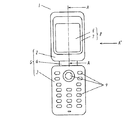
図1は、本発明の実施の形態1に係る情報端末装置である折畳み式携帯電話を開いた状態を示す正面図である。図1において示されるように、折畳み式携帯電話1は、本体ケース5を備える。本体ケース5は、上ケース2と、下ケース3と、上ケース2と下ケース3とを連結する連結部4を備える。上ケース2は、上ケース2の内部から映し出された画像を透過し、音が出力されるパネル8を備える。パネル8は、透明で上ケース2の内部を見ることができる透明パネル6と、不透明で上ケース2の内部を見ることができない不透明パネル7とを備える。下ケース3は各種スイッチ等により構成される操作部9を備える。
(Embodiment 1)
FIG. 1 is a front view showing a state in which a foldable mobile phone which is an information terminal device according to
図2は、図1において線A−Aに沿う断面を矢印A’の方向から見たときの断面図である。図2において示されるように、上ケース2には、正面に外部に露出した透明パネル6と不透明パネル7とから構成されたパネル8が接着剤16を介して結合されている。上ケース2の内部には、画像を表示する画像表示部10が設けられている。画像表示部10の上面は、透明パネル6で覆われている。画像表示部10から映し出される画像は、この透明パネル6を介して、外部に視認可能となっている。また、上ケース2の内部には、不透明で、音を出力するスピーカ11が設けられている。スピーカ11の上面は、不透明パネル7で覆われている。スピーカ11は、この不透明パネル7によって外部から視認できなくなっている。
2 is a cross-sectional view of the cross section taken along line AA in FIG. 1 when viewed from the direction of the arrow A ′. As shown in FIG. 2, a
図2において示されるように、透明パネル6と、不透明パネル7と、画像表示部10と、スピーカ11とから密閉空間13が形成されている。スピーカ11は、電気信号に応じて振動板を振動させることで音を放射する電気機械音響変換器により構成されている。このスピーカ11から密閉空間13へ放出された音により透明パネル6と不透明パネル7からなるパネル8が振動し放音するように構成されている。
As shown in FIG. 2, a sealed
透明パネル6と不透明パネル7とからなるパネル8は、薄型化を目的として平面状に形成されている。このパネル8の一部にはデザインとしての模様等が描かれていてもよい。例えば、透明パネル6の表面や裏面に凹凸形状等の模様が描かれていてもよいし、不透明パネル7の表面にロゴ等の模様が描かれていてもよい。
The
透明パネル6は、さらに、入力手段の機能を有する。すなわち、透明パネル6は、タッチパネルを有する。タッチパネルは、静電式や抵抗式のいずれの方式でもよい。上ケース2の内部には、ユーザがタッチパネルである透明パネル6に入力操作したことを認識する認識手段が設けられている。この認識手段は、電子回路12に組み込まれている。
The
上ケース2の内部には画像表示部10を制御する電子回路12が設けられている。電子回路12によって、画像表示部10には、操作メニューアイコンが表示される。画像表示部10に表示された操作メニューアイコンは、透明パネル6を介して外部に視認可能となっている。
An
電子回路12には、認識手段の認識結果に基づいて、スピーカ11を制御する制御手段がさらに組み込まれている。これにより、画像表示部10に表示された操作メニューアイコンに対応する透明パネル6の位置にユーザが押圧すると、認識手段は、ユーザの押圧位置を認識する。そして、制御手段は、認識手段が認識した押圧位置に対応する操作メニューを選択した結果の画面を画像表示部10に表示させる。さらに、制御手段は、スピーカ11の出力を変化させる。例えば、制御手段は、ユーザが透明パネル6のどの位置を押圧しても、押圧位置でのパネル8の振動が、一定になるようにスピーカ11の出力を制御する。これにより、透明パネル6のうち、スピーカ11から遠い位置でも押圧による振動を与えることができるとともに、スピーカ11からの距離に関係なく一定の強さの振動を与えることができ、ユーザの違和感を無くすことができる。また、制御手段は、押圧位置によって、パネル8が振動する間隔や周期を変化させるようにスピーカ11を制御してもよい。これによって、ユーザが透明パネル6に映し出された画像表示部10の画面を視認しなくても、特定のメニューを選択したことをユーザが認識することができる。また、制御手段は、最低共振周波数(f0)よりも低い周波数の信号でスピーカ11を駆動することが望ましい。これにより、パネル8が振動する際に、ユーザに音が聞こえないようにするとともに、大きな振幅量と大きな時間間隔を確保して、ユーザの指先に確実に振動を伝えることができる。また、制御手段は、スピーカ11に入力可能な最大値よりも小さい入力信号でスピーカ11を駆動することが望ましい。これにより、スピーカ11の故障を防止することができる。さらに、制御手段は、正弦波信号で前記スピーカを駆動することが望ましい。これにより、ユーザの指先に心地よい振動をスムースに確実に伝えることができる。
The
また、塗装や印刷等の手段により不透明にされた不透明パネル7がスピーカ11を覆っているので、本来外観上使用者に見せる必要のないスピーカ11が外部から隠される。これにより、ユーザが、透明パネルのうちスピーカを覆う部分を、ボタンと間違えて押したり、気になって押してしまったりすることを防止することができる。また、スピーカ11を覆うパネル8が不透明パネル7であるため、不透明パネル7がユーザに押されなくなり、急激な圧力変化によってスピーカが破損することを防止し、スピーカ11の品質を維持することができる。
Moreover, since the
スピーカ11から放出される音は、透明パネル6や不透明パネル7からなるパネル8を介して、外部に放音される。したがって、使用者は、透明パネル6に画像が表示されるとともに、透明パネル6から放音されるように感じることができる。
The sound emitted from the
(実施の形態2)
以下、実施の形態2を用いて、本発明の他の局面について説明する。
(Embodiment 2)
Hereinafter, other aspects of the present invention will be described using the second embodiment.
図3は本発明の実施の形態2の情報端末装置1の上ケース2の要部断面図である。
FIG. 3 is a cross-sectional view of the main part of the
図3において、実施の形態1と異なる部分についてのみ説明すると、上ケース2の内部にスピーカ11を備え、上ケース2に設けた音孔14を介して密閉空間13へ音を伝達しパネル8が振動し放音するように構成されている。
In FIG. 3, only the parts different from the first embodiment will be described. The
これによりスピーカ11から出た音と、音孔14と密閉空間13を利用し音質を調整することが可能となり、小型化や薄型化された情報端末装置の高音質化を実現することができる。
As a result, it is possible to adjust the sound quality using the sound emitted from the
(実施の形態3)
以下、実施の形態3を用いて、本発明の他の局面について説明する。
(Embodiment 3)
Hereinafter, other aspects of the present invention will be described using the third embodiment.
図4は本発明の実施の形態3の情報端末装置1の上ケース2の要部断面図である。
FIG. 4 is a cross-sectional view of the main part of the
図4において、実施の形態1と異なる部分についてのみ説明すると、上ケース2の内部にスピーカ11を備え、上ケース2に接続された音響管15を介し密閉空間13へ音を伝達し透明パネル6が振動し放音するように構成されている。
In FIG. 4, only the parts different from the first embodiment will be described. The
これによりスピーカ11を画像表示部10と水平方向に並べて配置するのではなく、重ねて配置することができ、限られた情報端末装置の中で映像表示部を最大限大型化することができ、低コストで、使用者から見た画像が表示される位置と音が放射される位置とが同じであり、情報端末装置のデザイン自由度向上を実現させることができる。
As a result, the
(実施の形態4)
以下、実施の形態4を用いて、本発明の他の局面について説明する。
(Embodiment 4)
Hereinafter, other aspects of the present invention will be described using the fourth embodiment.
図5は本発明の実施の形態4の情報端末装置1の上ケース2の要部断面図である。
FIG. 5 is a cross-sectional view of the main part of the
図5において、実施の形態1から実施の形態3と異なる部分についてのみ説明すると、パネル8は上ケース2に対して弾性体17を介して取り付けられ構成されている。
In FIG. 5, only portions different from the first to third embodiments will be described. The
これにより、スピーカ11から放出される音を放音するパネル8の固有共振周波数を低下させることができ、スピーカ11の音質を忠実に再現することができ、情報端末装置における高音質化を実現することができる。
As a result, the natural resonance frequency of the
(実施の形態5)
以下、実施の形態5を用いて、本発明の他の局面について説明する。
(Embodiment 5)
Hereinafter, other aspects of the present invention will be described using the fifth embodiment.
図6は本発明の実施の形態5の情報端末装置1の上ケース2の要部断面図である。
FIG. 6 is a cross-sectional view of the main part of the
図6において、実施の形態1と異なる部分についてのみ説明すると、パネル8は湾曲形状に形成され構成されている。
In FIG. 6, only the portions different from the first embodiment will be described. The
これにより全体的に丸みを帯びたデザインに対しても情報端末装置のデザイン性を損なうことなく、小型化や薄型化が可能となり更なるデザイン自由度向上を実現させることができる。 As a result, the design of the information terminal device can be reduced and the design can be reduced without impairing the design of the information terminal device even with respect to the overall rounded design, and further improvement in design flexibility can be realized.
本発明は、透明パネルのうちスピーカを覆う部分が押されてスピーカが破損することを防止する情報端末装置として有用である。 INDUSTRIAL APPLICABILITY The present invention is useful as an information terminal device that prevents a speaker from being damaged by pressing a portion of the transparent panel that covers the speaker.
1 情報端末装置
2 上ケース
3 下ケース
4 連結部
5 本体ケース
6 透明パネル
7 不透明パネル
8 パネル
9 操作部
10 画像表示部
11 スピーカ
12 電子回路
13 密閉空間
14 音孔
15 音響管
16 接着剤
17 弾性体
DESCRIPTION OF
Claims (3)
Priority Applications (2)
| Application Number | Priority Date | Filing Date | Title |
|---|---|---|---|
| JP2008253116A JP5401898B2 (en) | 2008-09-30 | 2008-09-30 | Information terminal equipment |
| PCT/JP2009/004623 WO2010038370A1 (en) | 2008-09-30 | 2009-09-16 | Information terminal device |
Applications Claiming Priority (1)
| Application Number | Priority Date | Filing Date | Title |
|---|---|---|---|
| JP2008253116A JP5401898B2 (en) | 2008-09-30 | 2008-09-30 | Information terminal equipment |
Publications (2)
| Publication Number | Publication Date |
|---|---|
| JP2010087736A JP2010087736A (en) | 2010-04-15 |
| JP5401898B2 true JP5401898B2 (en) | 2014-01-29 |
Family
ID=42073154
Family Applications (1)
| Application Number | Title | Priority Date | Filing Date |
|---|---|---|---|
| JP2008253116A Expired - Fee Related JP5401898B2 (en) | 2008-09-30 | 2008-09-30 | Information terminal equipment |
Country Status (2)
| Country | Link |
|---|---|
| JP (1) | JP5401898B2 (en) |
| WO (1) | WO2010038370A1 (en) |
Families Citing this family (5)
| Publication number | Priority date | Publication date | Assignee | Title |
|---|---|---|---|---|
| CN102859472B (en) * | 2010-11-19 | 2016-06-08 | 京瓷株式会社 | Electronic equipment and possess the portable terminal of this electronic equipment |
| JP2013044911A (en) * | 2011-08-24 | 2013-03-04 | Panasonic Corp | Display device |
| KR101332553B1 (en) * | 2011-12-20 | 2013-11-22 | 엘지전자 주식회사 | Mobile terminal |
| JP2013141148A (en) * | 2012-01-05 | 2013-07-18 | Kyocera Corp | Electronic device |
| KR101345960B1 (en) * | 2012-02-29 | 2014-01-06 | 주식회사 팬택 | Terminal having speaker unit |
Family Cites Families (4)
| Publication number | Priority date | Publication date | Assignee | Title |
|---|---|---|---|---|
| JP3949912B2 (en) * | 2000-08-08 | 2007-07-25 | 株式会社エヌ・ティ・ティ・ドコモ | Portable electronic device, electronic device, vibration generator, notification method by vibration and notification control method |
| JP3763570B2 (en) * | 2001-06-28 | 2006-04-05 | 松下電器産業株式会社 | Speaker system, portable terminal device, and electronic device |
| JP2005117117A (en) * | 2003-10-03 | 2005-04-28 | Matsushita Electric Ind Co Ltd | Mobile telephone with revolving upper case |
| JP4267554B2 (en) * | 2004-10-29 | 2009-05-27 | ホシデン株式会社 | Display structure of electronic device and electronic device provided with the same |
-
2008
- 2008-09-30 JP JP2008253116A patent/JP5401898B2/en not_active Expired - Fee Related
-
2009
- 2009-09-16 WO PCT/JP2009/004623 patent/WO2010038370A1/en active Application Filing
Also Published As
| Publication number | Publication date |
|---|---|
| WO2010038370A1 (en) | 2010-04-08 |
| JP2010087736A (en) | 2010-04-15 |
Similar Documents
| Publication | Publication Date | Title |
|---|---|---|
| WO2013175778A1 (en) | Electronic device and panel device | |
| JP5255142B1 (en) | Electronics | |
| JP5186900B2 (en) | Vibrating body, input device and electronic device | |
| JP4631443B2 (en) | I / O device with tactile function and electronic device | |
| JP4925767B2 (en) | Touch screen assembly, terminal and terminal control method | |
| WO2013094391A1 (en) | Electronic device | |
| JP2008225690A (en) | Vibration body, tactile sense function-equipped input device, and electronic equipment | |
| JP2008181365A (en) | Portable device | |
| JP6073071B2 (en) | Electronics | |
| WO2002021881A1 (en) | Display window having voice input/output function | |
| JP5401898B2 (en) | Information terminal equipment | |
| JPWO2012057214A1 (en) | Electronic device and portable terminal equipped with the same | |
| JP5968018B2 (en) | Electronics | |
| JP4987175B1 (en) | Electronic device and portable terminal equipped with the same | |
| US9826314B2 (en) | Electronic apparatus | |
| JP2013243615A (en) | Electronic apparatus | |
| JP6000642B2 (en) | Electronics | |
| JP5067346B2 (en) | Electronics | |
| JP6006530B2 (en) | Electronics | |
| JP6005999B2 (en) | Electronics | |
| WO2015033548A1 (en) | Electronic device | |
| JP2006157497A (en) | Electronic part, and electronic equipment and device using the same | |
| WO2014098031A1 (en) | Electronic apparatus provided with bone conduction vibration element | |
| WO2013103025A1 (en) | Electronic device | |
| JP2013242814A (en) | Electronic apparatus |
Legal Events
| Date | Code | Title | Description |
|---|---|---|---|
| A621 | Written request for application examination |
Free format text: JAPANESE INTERMEDIATE CODE: A621 Effective date: 20110901 |
|
| RD01 | Notification of change of attorney |
Free format text: JAPANESE INTERMEDIATE CODE: A7421 Effective date: 20111013 |
|
| RD01 | Notification of change of attorney |
Free format text: JAPANESE INTERMEDIATE CODE: A7421 Effective date: 20121214 |
|
| A131 | Notification of reasons for refusal |
Free format text: JAPANESE INTERMEDIATE CODE: A131 Effective date: 20130514 |
|
| A521 | Request for written amendment filed |
Free format text: JAPANESE INTERMEDIATE CODE: A523 Effective date: 20130704 |
|
| TRDD | Decision of grant or rejection written | ||
| A01 | Written decision to grant a patent or to grant a registration (utility model) |
Free format text: JAPANESE INTERMEDIATE CODE: A01 Effective date: 20131001 |
|
| A61 | First payment of annual fees (during grant procedure) |
Free format text: JAPANESE INTERMEDIATE CODE: A61 Effective date: 20131014 |
|
| R151 | Written notification of patent or utility model registration |
Ref document number: 5401898 Country of ref document: JP Free format text: JAPANESE INTERMEDIATE CODE: R151 |
|
| LAPS | Cancellation because of no payment of annual fees |