JP5400052B2 - Method for applying a thermosetting coating to a patterned substrate - Google Patents
Method for applying a thermosetting coating to a patterned substrate Download PDFInfo
- Publication number
- JP5400052B2 JP5400052B2 JP2010530231A JP2010530231A JP5400052B2 JP 5400052 B2 JP5400052 B2 JP 5400052B2 JP 2010530231 A JP2010530231 A JP 2010530231A JP 2010530231 A JP2010530231 A JP 2010530231A JP 5400052 B2 JP5400052 B2 JP 5400052B2
- Authority
- JP
- Japan
- Prior art keywords
- sheet
- template
- pattern
- thermoplastic material
- asphalt surface
- Prior art date
- Legal status (The legal status is an assumption and is not a legal conclusion. Google has not performed a legal analysis and makes no representation as to the accuracy of the status listed.)
- Expired - Fee Related
Links
- 238000000034 method Methods 0.000 title claims description 37
- 239000000758 substrate Substances 0.000 title claims description 23
- 229920001187 thermosetting polymer Polymers 0.000 title claims description 7
- 238000000576 coating method Methods 0.000 title description 36
- 239000011248 coating agent Substances 0.000 title description 35
- 239000010426 asphalt Substances 0.000 claims description 74
- 239000012815 thermoplastic material Substances 0.000 claims description 26
- 238000010438 heat treatment Methods 0.000 claims description 21
- 238000011065 in-situ storage Methods 0.000 claims description 10
- 239000004576 sand Substances 0.000 claims description 7
- 239000002245 particle Substances 0.000 claims description 6
- 239000000463 material Substances 0.000 claims description 5
- 238000001816 cooling Methods 0.000 claims description 2
- 229920001169 thermoplastic Polymers 0.000 description 29
- 239000004416 thermosoftening plastic Substances 0.000 description 29
- VYPSYNLAJGMNEJ-UHFFFAOYSA-N Silicium dioxide Chemical compound O=[Si]=O VYPSYNLAJGMNEJ-UHFFFAOYSA-N 0.000 description 7
- 239000003638 chemical reducing agent Substances 0.000 description 7
- 239000011440 grout Substances 0.000 description 6
- 230000000007 visual effect Effects 0.000 description 6
- 239000010410 layer Substances 0.000 description 4
- 239000011449 brick Substances 0.000 description 3
- 239000002826 coolant Substances 0.000 description 3
- 230000001965 increasing effect Effects 0.000 description 3
- 239000007788 liquid Substances 0.000 description 3
- 239000000654 additive Substances 0.000 description 2
- 239000003086 colorant Substances 0.000 description 2
- 239000004567 concrete Substances 0.000 description 2
- 230000000694 effects Effects 0.000 description 2
- 239000004570 mortar (masonry) Substances 0.000 description 2
- 238000000059 patterning Methods 0.000 description 2
- 238000003825 pressing Methods 0.000 description 2
- NIXOWILDQLNWCW-UHFFFAOYSA-N acrylic acid group Chemical group C(C=C)(=O)O NIXOWILDQLNWCW-UHFFFAOYSA-N 0.000 description 1
- 230000000996 additive effect Effects 0.000 description 1
- 239000011324 bead Substances 0.000 description 1
- 239000011230 binding agent Substances 0.000 description 1
- 239000011247 coating layer Substances 0.000 description 1
- 150000001875 compounds Chemical class 0.000 description 1
- 230000006835 compression Effects 0.000 description 1
- 238000007906 compression Methods 0.000 description 1
- 230000008878 coupling Effects 0.000 description 1
- 238000010168 coupling process Methods 0.000 description 1
- 238000005859 coupling reaction Methods 0.000 description 1
- 238000005034 decoration Methods 0.000 description 1
- 238000004049 embossing Methods 0.000 description 1
- 230000002708 enhancing effect Effects 0.000 description 1
- 239000003822 epoxy resin Substances 0.000 description 1
- 239000011521 glass Substances 0.000 description 1
- 238000009434 installation Methods 0.000 description 1
- 229920000126 latex Polymers 0.000 description 1
- 239000004816 latex Substances 0.000 description 1
- 239000000155 melt Substances 0.000 description 1
- 238000002844 melting Methods 0.000 description 1
- 230000008018 melting Effects 0.000 description 1
- 239000000203 mixture Substances 0.000 description 1
- 238000012986 modification Methods 0.000 description 1
- 230000004048 modification Effects 0.000 description 1
- 229920000647 polyepoxide Polymers 0.000 description 1
- 239000011253 protective coating Substances 0.000 description 1
- 230000001681 protective effect Effects 0.000 description 1
- 238000003303 reheating Methods 0.000 description 1
- 239000000377 silicon dioxide Substances 0.000 description 1
- 239000007921 spray Substances 0.000 description 1
- 239000002344 surface layer Substances 0.000 description 1
- XLYOFNOQVPJJNP-UHFFFAOYSA-N water Substances O XLYOFNOQVPJJNP-UHFFFAOYSA-N 0.000 description 1
Images


Classifications
-
- E—FIXED CONSTRUCTIONS
- E01—CONSTRUCTION OF ROADS, RAILWAYS, OR BRIDGES
- E01C—CONSTRUCTION OF, OR SURFACES FOR, ROADS, SPORTS GROUNDS, OR THE LIKE; MACHINES OR AUXILIARY TOOLS FOR CONSTRUCTION OR REPAIR
- E01C19/00—Machines, tools or auxiliary devices for preparing or distributing paving materials, for working the placed materials, or for forming, consolidating, or finishing the paving
- E01C19/22—Machines, tools or auxiliary devices for preparing or distributing paving materials, for working the placed materials, or for forming, consolidating, or finishing the paving for consolidating or finishing laid-down unset materials
- E01C19/43—Machines or arrangements for roughening or patterning freshly-laid paving courses, e.g. indenting rollers
-
- E—FIXED CONSTRUCTIONS
- E01—CONSTRUCTION OF ROADS, RAILWAYS, OR BRIDGES
- E01C—CONSTRUCTION OF, OR SURFACES FOR, ROADS, SPORTS GROUNDS, OR THE LIKE; MACHINES OR AUXILIARY TOOLS FOR CONSTRUCTION OR REPAIR
- E01C23/00—Auxiliary devices or arrangements for constructing, repairing, reconditioning, or taking-up road or like surfaces
- E01C23/02—Devices for making, treating or filling grooves or like channels in not-yet-hardened paving, e.g. for joints or markings; Removable forms therefor; Devices for introducing inserts or removable insert-supports in not-yet-hardened paving
- E01C23/028—Positioning or producing markings, e.g. by forcing marking materials into the surface, by scoring
-
- E—FIXED CONSTRUCTIONS
- E01—CONSTRUCTION OF ROADS, RAILWAYS, OR BRIDGES
- E01C—CONSTRUCTION OF, OR SURFACES FOR, ROADS, SPORTS GROUNDS, OR THE LIKE; MACHINES OR AUXILIARY TOOLS FOR CONSTRUCTION OR REPAIR
- E01C23/00—Auxiliary devices or arrangements for constructing, repairing, reconditioning, or taking-up road or like surfaces
- E01C23/14—Auxiliary devices or arrangements for constructing, repairing, reconditioning, or taking-up road or like surfaces for heating or drying foundation, paving, or materials thereon, e.g. paint
-
- E—FIXED CONSTRUCTIONS
- E01—CONSTRUCTION OF ROADS, RAILWAYS, OR BRIDGES
- E01F—ADDITIONAL WORK, SUCH AS EQUIPPING ROADS OR THE CONSTRUCTION OF PLATFORMS, HELICOPTER LANDING STAGES, SIGNS, SNOW FENCES, OR THE LIKE
- E01F9/00—Arrangement of road signs or traffic signals; Arrangements for enforcing caution
- E01F9/50—Road surface markings; Kerbs or road edgings, specially adapted for alerting road users
- E01F9/506—Road surface markings; Kerbs or road edgings, specially adapted for alerting road users characterised by the road surface marking material, e.g. comprising additives for improving friction or reflectivity; Methods of forming, installing or applying markings in, on or to road surfaces
- E01F9/512—Preformed road surface markings, e.g. of sheet material; Methods of applying preformed markings
Description
本出願は、熱硬化性コーティングを、刻印されたアスファルトの表面などの模様付けされた基材に施与する方法に関する。コーティングは、1つまたは複数の予備形成された熱可塑性シートを基材上に置き、そのシートを原位置で加熱して熱可塑性材料を下にある模様に合致させることによって施与することができる。 The present application relates to a method of applying a thermosetting coating to a patterned substrate, such as a stamped asphalt surface. The coating can be applied by placing one or more preformed thermoplastic sheets on a substrate and heating the sheets in situ to match the thermoplastic material to the underlying pattern. .
アスファルト表面および他の基材に模様を形成するさまざまな方法が、従来技術で知られている。本出願人は、米国特許状第5,215,402号(特許文献1)の権利者であり、この特許では、除去可能な型板を用いてアスファルト表面に模様を形成する方法を記載している。その型板は、柔軟なアスファルト表面に押し込まれて、たとえばレンガ、玉石、連結型舗装石等の外観を模倣する所定の模様を刻印する。そして型板は持ち上げられてアスファルト表面から取り除かれ、アスファルトは硬化させられる。 Various methods for forming patterns on asphalt surfaces and other substrates are known in the prior art. Applicant is the right holder of US Pat. No. 5,215,402, which describes a method of forming a pattern on an asphalt surface using a removable template. Yes. The template is pressed into a flexible asphalt surface to imprint a predetermined pattern that mimics the appearance of, for example, bricks, cobblestones, connected paving stones, and the like. The template is then lifted away from the asphalt surface and the asphalt is cured.
’402における発明の1つの実施形態では、レンガおよびモルタルまたは他の所望の視覚的効果を高めるために、セメント質の薄いコーティング層を、刻印されたアスファルトに施与することができる。装飾用コーティングは、たとえば粉体コンクリート、およびアスファルト表面全体に広がって硬化させられるスラリー状の着色剤を施すことによって施与され得る。これは、比較的時間がかかる、労働集約的な方法である。さまざまな他のアクリル系、エポキシ樹脂系、またはラテックスベースの保護コーティングも同様に、表面をシールしかつその視覚的魅力を高めるために、型押し工程の後、刻印された表面に施与することができる。 In one embodiment of the invention at '402, a thin cementitious coating layer can be applied to the stamped asphalt to enhance brick and mortar or other desired visual effects. The decorative coating can be applied, for example, by applying powdered concrete and a slurry-like colorant that spreads and cures across the asphalt surface. This is a relatively time consuming and labor intensive method. Various other acrylic, epoxy resin, or latex-based protective coatings may also be applied to the imprinted surface after the embossing process to seal the surface and enhance its visual appeal Can do.
’402における方法の1つの欠点は、特に交通量が多い地域において装飾用コーティングが時間経過に伴ってすり減ることがあることである。さらに、上記で述べたように、液状のコーティングの施与は時間がかかるものであり、技術的困難も伴う。たとえば、コーティングが一様な深さに広げられない場合、視覚的効果が魅力的でないという結果になり得る。したがって、予備形成された熱可塑性シートに熱を施与することによってアスファルト表面をコーティングするための改良された方法の必要性が生じている。 One drawback of the method at '402 is that the decorative coating can wear off over time, especially in high traffic areas. Furthermore, as mentioned above, the application of a liquid coating is time consuming and involves technical difficulties. For example, if the coating is not spread to a uniform depth, the visual effect can be unattractive. Accordingly, a need has arisen for an improved method for coating asphalt surfaces by applying heat to preformed thermoplastic sheets.
機能または装飾の目的でその場で熱可塑性コーティングに模様を型押しすることが従来技術において知られている。たとえば、プリズモユニバーサルコーポレーション社(Prismo Universal Corporation)は、熱可塑性物質の比較的厚い層(すなわち約15ミリメートル)を、加熱された柔軟な形態にある基材に施与するための方法を使用しており、これを説明している。熱可塑性物質は、ここで、絶縁された熱保護用衣服を着用する作業者によって所望の模様に手動で打刻される。この方法は、非常に労働集約的なものであり、危険が潜んでいる。打刻は手動で行われるため、広い表面領域にわたって複雑な模様を一様に与えることは困難である。さらに、この打刻は、下にある基材ではなく厚い熱可塑性層に模様を型押しすることを意図している。 It is known in the prior art to emboss a pattern on a thermoplastic coating in situ for functional or decorative purposes. For example, Prismo Universal Corporation uses a method to apply a relatively thick layer of thermoplastic (ie, about 15 millimeters) to a substrate in a heated flexible form. And explain this. The thermoplastic material is now manually stamped into the desired pattern by an operator wearing insulated thermal protective clothing. This method is very labor intensive and can be dangerous. Since the stamping is performed manually, it is difficult to uniformly give a complicated pattern over a wide surface area. Furthermore, this engraving is intended to emboss the pattern into a thick thermoplastic layer rather than the underlying substrate.
したがって、熱硬化性コーティングを、刻印されたアスファルト表面などの模様付けされた基材に施与するための改良された方法および材料の必要性が生じてきている。 Thus, a need has arisen for improved methods and materials for applying thermosetting coatings to patterned substrates such as stamped asphalt surfaces.
本発明によれば、(a)第1の模様を基材に形成する工程と、(b)予備形成された熱硬化性シートを基材に配置する工程と、(c)第1の模様に合致する形でシートが基材に接着するのに十分な温度まで、原位置でシートを加熱する工程とを含む、コーティングを基材に施与する方法が提供される。 According to the present invention, (a) a step of forming a first pattern on a substrate, (b) a step of placing a pre-formed thermosetting sheet on the substrate, and (c) a first pattern Heating the sheet in situ to a temperature sufficient for the sheet to adhere to the substrate in a conforming manner, and a method of applying the coating to the substrate is provided.
好ましくは、シートは、熱可塑性材料から形成され、基材は、アスファルト表面である。シートは、アスファルト表面と接触する第1の表面と、アスファルト表面と接触しない第2の表面とを含むことができる。シートは、熱可塑性物質が、0.75〜3.75ミリメートル(30〜150ミル)またはより好ましくは1.25〜3.13ミリメートル(50〜125ミル)の厚さでアスファルト表面上にコーティングされるように、薄いプロファイルを有することが好ましい。 Preferably, the sheet is formed from a thermoplastic material and the substrate is an asphalt surface. The sheet can include a first surface that contacts the asphalt surface and a second surface that does not contact the asphalt surface. The sheet is coated on the asphalt surface with a thermoplastic material at a thickness of 0.75 to 3.75 millimeters (30 to 150 mils) or more preferably 1.25 to 3.13 millimeters (50 to 125 mils). Thus, it is preferable to have a thin profile.
第1の模様は、アスファルト表面が柔軟な状態にあるときにアスファルト表面に形成することができる。たとえば、第1の模様は、高温のアスファルトを含む直近に形成されたアスファルト表面または既存の再加熱されたアスファルト表面に形成することができる。1つの実施形態では、第1の模様は、アスファルト表面が柔軟な状態にある間にアスファルト表面上に型板を置き、この型板をアスファルト表面に入れて第1の模様を形成するように刻印し、模様を露出させるために型板をアスファルト表面から除去することによって形成される。 The first pattern can be formed on the asphalt surface when the asphalt surface is in a flexible state. For example, the first pattern can be formed on a recently formed asphalt surface that includes hot asphalt or an existing reheated asphalt surface. In one embodiment, the first pattern is imprinted to place a template on the asphalt surface while the asphalt surface is in a flexible state and place the template on the asphalt surface to form the first pattern. And by removing the template from the asphalt surface to expose the pattern.
原位置でシートを加熱する工程は、シートの上方に延在する支持枠を有する加熱装置を提供することによってシートの温度を除々に上昇させる工程を含むことができ、この装置は、シートの上方を周期的に通過する進行経路で支持枠上を移動するように装着された少なくとも1つのヒータを有する。シートは、65.6〜232.2℃(約150〜450°F)の間、より好ましくは148.9〜204.4℃(300〜400°F)の間の温度まで加熱され得る。 The step of heating the sheet in situ may include gradually increasing the temperature of the sheet by providing a heating device having a support frame extending above the sheet, the device being above the sheet. At least one heater mounted so as to move on the support frame in a traveling path that periodically passes through the support frame. The sheet may be heated to a temperature between 65.6-232.2 ° C (about 150-450 ° F), more preferably between 148.9-204.4 ° C (300-400 ° F).
シートは、複数の個別のセクションに副分割可能でよい。追加的にまたは代替的に、アスファルト表面を覆うように互いに隣接して整列され得る複数の別個のシートが提供されてよい。シートのサイズ、形状、色、および質感は、機能および/または装飾の目的に合わせて選択することができる。たとえば、各々のシートは、アスファルト表面に形成された第1の模様に合致する第2の模様で形成されてよい。 The sheet may be subdivided into a plurality of individual sections. Additionally or alternatively, a plurality of separate sheets may be provided that can be aligned adjacent to each other to cover the asphalt surface. The size, shape, color, and texture of the sheet can be selected for function and / or decoration purposes. For example, each sheet may be formed with a second pattern that matches the first pattern formed on the asphalt surface.
本発明の代替の実施形態では、第1の模様は、熱可塑性シートおよび基材に同時に形成され得る。この実施形態では、予備形成された熱硬化性シートが、模様付けされていない基材上に置かれる。シートは、次いで、シートの第1の表面が基材に接着するのに十分な温度まで原位置で除々に加熱される。シートおよび基材は、次いで、シートの第2の露出面上に置かれた型板を押し込むなどにより、第1の模様を形成するように刻印される。型板をシートの第2の表面上に置く前に、型板と予備形成されたシートの高温の熱可塑性材料の間の接着を最小限に抑えるために、結合還元剤または冷却剤で第2の表面を処理することができる。 In an alternative embodiment of the present invention, the first pattern can be formed simultaneously on the thermoplastic sheet and the substrate. In this embodiment, a pre-formed thermoset sheet is placed on an unpatterned substrate. The sheet is then gradually heated in situ to a temperature sufficient for the first surface of the sheet to adhere to the substrate. The sheet and substrate are then imprinted to form a first pattern, such as by pressing a template placed on the second exposed surface of the sheet. Before placing the template on the second surface of the sheet, the second with a combined reducing agent or coolant to minimize adhesion between the hot thermoplastic material of the template and the preformed sheet. The surface can be treated.
本発明の別の代替の実施形態では、第1の模様により精密に熱可塑性物質を適合させるために、第2の型板を用いて、熱可塑性物質を加熱した後に打刻することができる。
図では、本発明の実施形態を示すが、どのような形であれ本発明の趣旨または範囲を制限するものとして解釈されてはならない。
In another alternative embodiment of the present invention, the second template can be used to stamp the thermoplastic material after it has been heated in order to more precisely match the thermoplastic material with the first pattern.
The figures illustrate embodiments of the invention, but should not be construed as limiting the spirit or scope of the invention in any way.
以下の説明を通して、本発明に対するより完璧な理解をもたらすために、特定の詳細が記載される。しかし、本発明は、これらの事項を伴うことなく実施することができる。他の場合においては、よく知られている要素は、本発明を不必要に曖昧にすることを回避するために詳細に示されておらず、または説明されていない。したがって、本明細書および図は、制限的な意味ではなく例示的なものとして見なされるものである。 Throughout the following description specific details are set forth in order to provide a more thorough understanding of the present invention. However, the present invention can be practiced without these matters. In other instances, well-known elements have not been shown or described in detail to avoid unnecessarily obscuring the present invention. Accordingly, the specification and drawings are to be regarded in an illustrative rather than a restrictive sense.
本出願は、熱硬化性コーティング10をアスファルト表面12などの模様付けされた基材に施与する方法に関する。図4〜6に示すように、コーティング10は、最初に、1つまたは複数の予備形成されたシート14の形態でアスファルト表面12に施与することができる。そしてシート14は、シート14とアスファルト表面12の間に一様な結合が達成されるまで、下記で説明するように原位置で除々に加熱され、それによってコーティング10を形成する。この加熱方法は、シート14を下にある表面12に形成された模様22に合致させ、それによってその装飾的または機能的効果を高める(図6および7)。
The present application relates to a method of applying a
本特許出願では、「原位置」で加熱するという用語は、液状の高温の熱可塑性物質を従来の方法で直接アスファルト表面12に施与してこれを硬化させるのではなく、予備形成されたシート14を設置場所で加熱することを示す。本特許出願では、「アスファルト」は、道路、ドライブウェイ、歩道などを建設するための舗装用化合物を意味し、この舗装用化合物は、タールなどの瀝青バインダおよび砂または砂利などの骨材の組合せで構成される。当業者によって理解されるように、本出願人の方法は、コンクリート、または硬化性コーティング10を受け入れ、これに接着することができる他の材料などの、他のタイプの模様付けされた基材にも適用され得る。
In this patent application, the term “in-situ” heating refers to a pre-formed sheet rather than applying liquid high temperature thermoplastic directly to the
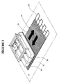
図4に最適に示すように、各々の予備形成されたシート14は、アスファルト表面12と接触する第1の表面16と、アスファルト表面12と接触しない第2の露出面18とを有する。本発明の1つの実施形態では、各々のシート14の表面16、18間の厚さは、0.75〜3.75ミリメートル(約30〜150ミル)の厚さの範囲内にあり、より具体的には1.25〜3.13ミリメートル(50〜125ミル)の厚さの範囲内にある。シート14は、熱可塑性材料から形成することができ、ラファージュロードマーキングス社(Lafarge Road Markings)、フリントトレーディングインコーポレイティッド社(Flint Trading,Inc.)およびエイブリィデニソンコーポレーション社(Avery Dennison Corporation)などのさまざまな供給者から入手可能である。シート14は、交通標識または企業のロゴなどの機能的目的に合わせて選択されてよく、あるいは単に装飾用でもよい。図8に示すように、複数のシート14が、アスファルト表面12を完全に覆うように重複しない構成で一緒に並置され得る。代替の実施形態では、隣り合うシート14の縁部分は、部分的に重複してよい。別の代替の実施形態では、シート14は、隣り合うシート14の間に空隙を維持するなどにより、アスファルト表面12を一部分だけ覆うように配置されてよい。さらに、各々のシート14は、連続的でも不連続的でもよい。たとえば、各々のシート14は、その中に形成された開口部または長穴を含み得る。当業者に明白になるように、シート14の形状および構造は、本発明から逸脱することなく変更することができる。
As best shown in FIG. 4, each preformed
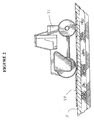
たとえば本願明細書に援用する特許文献1で説明した本出願人の方法によって、模様をアスファルト表面12に形成することができる。より具体的には、型板20が、アスファルト表面12が柔軟な状態(すなわち高温のアスファルトで圧延されたばかり、あるいは表面の再加熱後)にある間にアスファルト表面12(図1および2)上に配置される。型板20は、次いで、ドラム・ローラ24または何らかの他の圧縮装置でアスファルト表面12内に押し込まれて、その中に模様22を形成する。たとえば、模様22は、レンガおよびモルタルの外観、または何らかの他の装飾外観を模倣する型押し模様でよい。型板20は、次いで、模様22を露出させるために表面12から除去される(図1)。代替の実施形態では、模様22は、表面12に形成された型押し模様ではなく突起部、または何らかの他の表面テクスチャリング(surface texturing)で構成することができる。模様22をアスファルト表面12に形成する他の類似の手段が、想定され得る。
For example, the pattern can be formed on the
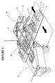
シート14を原位置で加熱する1つの手段は、図3に示されており、本願明細書に援用するWO 03/048458 Alで説明されている。この実施形態では、持ち運び可能な表面加熱装置26が、アスファルト表面12およびその上に置かれたシート14を加熱するために設けられている。アスファルト表面は、加熱工程が開始する前は乾燥していることが好ましい。図示された実施形態では、装置26は、支持枠28と、支持枠28上で移動するように支持される複数の赤外線ヒータ30とを含む。たとえば、支持枠28は、支持脚32およびハウジング34によってアスファルト表面12の上方で支持された細長いレール30を含むことができる。ヒータ・トラック36が、レール30上の往復移動のために設けられている。トラック36は、ヒータ30の群(bank)を表面12に近い位置(たとえば地上より約5.08センチメートル(2インチ))で支持している。
One means of heating the
図4および5に示すように、予備形成された熱可塑性シート14が、アスファルト表面12上に置かれて模様22に重なった後、熱可塑性材料を除々に溶融させるために赤外線ヒータ30をシート14の上方で往復させる(図5では、明確性を高めるために、ヒータ30を備える装置26の一部分のみを示している)。図1の加熱方法の重要な利点は、比較的大きいシート14またはシート14の群、および下にあるアスファルト表面12を、除々にかつ均一に加熱できることである。この手法は、大きな領域の均一な加熱に使用することが容易にできず、熱可塑性材料および/または下にある基材を焦がす傾向を有するという携帯型トーチヒータの欠点を回避する。たとえば、その組成によっては、一部の熱可塑性シート14および/またはアスファルト表面12は、約162.8℃(325°F)を超える温度に持続的にさらされた際に焦げる可能性がある。本出願人の加熱方法の1つの実施形態によれば、アスファルト表面12および熱可塑性シート14は、各々の加熱サイクルの後、部分的に冷却させられる。したがって、表面12(およびこれに施与されたシート14)の温度は、熱可塑性物質/アスファルトの接着に適切な所望の温度が達成されるまで、連続的な加熱サイクルによって除々に上昇する。それによってアスファルト表面12は、比較的ゆっくりの熱ソーク(heat soak)にかけられて、アスファルトの最上の表面層の下方で熱がシート14を貫通しかつその周りに除々に浸透することが可能になる。本発明の1つの実施形態によれば、表面12およびシート14は、65.6〜232.2℃(150〜450°F)の範囲内、最も好ましくは65.6〜232.2℃(約150〜450°F)の範囲内の温度まで除々に加熱される。
4 and 5, after the preformed
図6および7に示すように、シート14は、十分な高さの温度まで加熱されたとき、溶融しかつアスファルト表面12に形成された模様22に合致し、アスファルト表面12上にコーティング10を形成する。次いで、熱源が除去され、コーティング10が硬化させられる。本発明の別の実施形態では、別の表面テクスチャリング(surface texturing)を創出する、あるいは装飾効果を増大させるために、コーティング10がまだ粘着状態にある間に着色剤または添加剤をコーティング10に施与することができる。図6に示すように、コーティング10は、所望の視覚的効果に応じて、表面模様22のすべてまたは一部に施与することができる。複数のシート14が使用される場合(図8および9)、シート14は、縁と縁とを合わせて整列されてよく、あるいは隣り合うシート14の間に空隙が維持されてよい(すなわち模様22で刻印された表面12の一部分は、コーティングされないままでよい)。
6 and 7, when heated to a sufficiently high temperature, the
図10〜12は、模様22がアスファルト表面12およびシート(複数可)14の両方に順次ではなく同時に形成される本発明の代替の実施形態を示している。この実施形態では、予備形成されたシート14が、模様付けされていないアスファルト表面12上に配置される。表面12は、圧延されたばかり、再加熱または未加熱の状態でよい。図5の実施形態の場合と同様に、熱可塑性材料を除々に溶融させるために、赤外線ヒータ30をシート14の上方で往復させることができる(図10)。シート14が、下にあるアスファルト表面12と接着するのに十分な高さの温度まで除々に加熱された後、結合還元剤がシート14の露出面18に施与される(図11)。たとえば、結合還元剤は、砂などの粒子結合破砕物40、または水冷却剤などの液体噴霧42でよく、層18に施与される。結合還元剤の目的は、層14と模様形成デバイスの間の接着を最小限に抑えることである。
FIGS. 10-12 illustrate an alternative embodiment of the present invention in which the
図12に示すように、模様形成デバイスは、除去可能な型板20を備えることができる。図示された実施形態では、型板20は、シート14および下にあるアスファルト表面12の両方に模様22を同時に型押しするために使用される。上記で示した結合還元剤は、型板20とシート14の露出面18の間の接着を最小限に抑えるが、シート14の表面16とアスファルト表面12の間の接着には影響を及ぼさない。それによって、薄い熱可塑性コーティング10をその上に有する、模様付けされたアスファルト表面12が得られる(図12)。
As shown in FIG. 12, the patterning device may include a
図13〜16は、本発明の別の実施形態を示している。この実施形態では、模様22が、型板20を用いてアスファルト表面12に形成され、次いで、シート(複数可)14が、刻印された表面上に配置され、上記で説明したように原位置で加熱される。これによってシート(複数可)14が、溶融しかつ模様22に合致し、アスファルト表面12上にコーティング10を形成する(図13および14)。本発明の別の実施形態によれば、熱可塑性コーティング10は、次いで、部分的に冷却させられ、加熱後打刻工程にかけられる。非限定的な例では、コーティング10は、60℃(140°F)の温度まで冷却させることができるが、この温度は、熱可塑性物質のタイプおよび周囲条件に応じて変化し得る。加熱後打刻工程は、熱可塑性物質がまだ柔軟である間に部分的に冷却されたコーティング10上に別の型板50を置く工程を含むことができる(図15)。好ましくは、型板50は、型板20の模様に合致する模様を有するが、打刻工程中、疑似グラウト・ラインまたは他の模様から熱可塑性物質がずれるのを回避するために、型板20よりわずかに小さい直径を有するワイヤ要素を有する。たとえば、型板20は、直径9.5ミリメートル(約3/8インチ)のワイヤ要素を有することができ、型板50は、直径6.35ミリメートル(約1/4インチ)のワイヤ要素を有することができる。型板50は、コーティング10内に押し込まれたとき、熱可塑性物質を下にある模様22により精密に合致させ、その結果、より鮮明でより良好に画定された視覚的外観が得られる。これは、打刻工程の前の図14の疑似グラウト・ラインと、打刻工程後の図16の疑似グラウト・ラインを比較することによって明らかになる。図14のグラウト・ラインは、浅い曲線状のプロファイルを有するが、図16のグラウト・ラインは、より深く、より良好に画定された曲線状のプロファイルを有し、このプロファイルは、アスファルト表面12に形成された模様22の輪郭および深さとより綿密に合致している。したがって、図16のグラウト・ラインは、所望の視覚的効果をより良好に模倣する。
Figures 13-16 illustrate another embodiment of the present invention. In this embodiment, the
本発明のこの実施形態では、熱可塑性物質は、所望の模様により綿密に合致させるために加熱後打刻工程にかけられるため、熱可塑性シート14は、本発明の他の実施形態よりも厚さにおいて幾分大きくなり得る。上記で示唆したように、シート14は、通常、0.75〜3.75ミリメートル(30〜150ミル)の厚さ、より具体的には1.25〜3.13ミリメートル(50〜125ミル)、または2.25〜3ミリメートル(90〜120ミル)の厚さの範囲内にある。本発明のこの実施形態では、シート14は、3.75〜6.25ミリメートル(150〜250ミル)の厚さの範囲内でよいが、より小さい厚さのシート14もまた使用されてよい。本発明の特定の実施形態では、4.38〜5.63ミリメートル(175〜225ミル)の範囲内の厚さを有するシートが使用されてよい。より厚いシート14は、耐久性がより大きく、砂、シリカ、またはガラス玉などの粒子状添加物に対する担体として作用する熱可塑性物質の量が増大するという利点を有する。本明細書において説明した本出願人の往復式加熱システムは、比較的厚い熱可塑性シートによって焦げまたは不完全な溶融を引き起こすことなく均一に加熱できるという利点を有する。
In this embodiment of the present invention, the
上記で説明した本発明の他の実施形態の1つの場合と同様に、結合還元剤40は、熱可塑性物質と型板50の間の接着を最小限に抑えるために、コーティング10の露出された上面が打刻される前にこの上面に施与され得る。たとえば、砂または他の骨材などの粒子結合破砕物を、型板50がコーティング10内に押し込まれる前にコーティング10上に投入することができる。これによって、押し込み工程後の型板50の除去が容易に進められる。粒子結合破砕物40は、熱可塑性物質内に浸透していき、その結果、耐久性の強化および滑り抵抗性の表面がもたらされる。図14および16に示すように、熱可塑性シート14は、上記で説明されたように従来のシートよりも厚いため、耐久性能を最適にするために、より大きく、より角度のある粒子を使用することができる。たとえば、3ミリメートル(120ミル)を超える骨材サイズを有する砂を使用することができる。
As in the case of one of the other embodiments of the present invention described above, the
上述の開示に照らして当業者に明白になるように、本発明の趣旨または範囲から逸脱することなく、本発明の実施において数多くの変更および改変が可能である。したがって、本発明の範囲は、添付の特許請求の範囲によって定義された実態によって解釈されるものとする。 Numerous changes and modifications can be made in the practice of the invention without departing from the spirit or scope of the invention, as will be apparent to those skilled in the art in light of the above disclosure. Accordingly, the scope of the invention should be construed according to the reality as defined by the appended claims.
Claims (9)
(b)第1の予備形成された熱硬化性シートを前記基材上に配置する工程と、
(c)前記第1の模様に合致する形で前記シートが前記基材に接着するのに十分な温度まで、原位置で前記シートを加熱する工程と、
(d)熱可塑性物質をより精密に該第1の模様に合致させるために、第2の型板を用いて前記熱可塑性物質を打刻する工程とを含む、熱可塑性コーティングをアスファルト基材に施与する方法。 (A) forming a first pattern on a substrate using a first template;
(B) placing a first pre-formed thermosetting sheet on the substrate;
(C) heating the sheet in situ to a temperature sufficient for the sheet to adhere to the substrate in a form consistent with the first pattern;
(D) stamping the thermoplastic material on the asphalt substrate using a second template to engrave the thermoplastic material in order to more precisely match the thermoplastic material to the first pattern. How to apply.
Applications Claiming Priority (3)
| Application Number | Priority Date | Filing Date | Title |
|---|---|---|---|
| US11/924,421 US8133540B2 (en) | 2002-12-03 | 2007-10-25 | Method of applying a thermally settable coating to a patterned substrate |
| US11/924,421 | 2007-10-25 | ||
| PCT/CA2008/001867 WO2009052619A1 (en) | 2007-10-25 | 2008-10-24 | Method of applying a thermally settable coating to a patterned substrate |
Publications (3)
| Publication Number | Publication Date |
|---|---|
| JP2011501006A JP2011501006A (en) | 2011-01-06 |
| JP2011501006A5 JP2011501006A5 (en) | 2012-01-05 |
| JP5400052B2 true JP5400052B2 (en) | 2014-01-29 |
Family
ID=39668302
Family Applications (1)
| Application Number | Title | Priority Date | Filing Date |
|---|---|---|---|
| JP2010530231A Expired - Fee Related JP5400052B2 (en) | 2007-10-25 | 2008-10-24 | Method for applying a thermosetting coating to a patterned substrate |
Country Status (9)
| Country | Link |
|---|---|
| US (1) | US8133540B2 (en) |
| EP (1) | EP2219866B1 (en) |
| JP (1) | JP5400052B2 (en) |
| AU (1) | AU2008316278B2 (en) |
| CA (1) | CA2608668C (en) |
| DK (1) | DK2219866T3 (en) |
| ES (1) | ES2469667T3 (en) |
| PT (1) | PT2219866E (en) |
| WO (1) | WO2009052619A1 (en) |
Families Citing this family (5)
| Publication number | Priority date | Publication date | Assignee | Title |
|---|---|---|---|---|
| US9045868B2 (en) * | 2012-01-10 | 2015-06-02 | Grant Eugene Farrell | Method and apparatus for stamping concrete |
| US8864409B2 (en) | 2012-12-13 | 2014-10-21 | Flint Trading, Inc | Method of forming an inlaid pattern in an asphalt surface from preformed template isometries |
| US8672580B1 (en) * | 2013-02-21 | 2014-03-18 | Butterfield Color, Inc. | Apparatus and method for imprinting a curved pathway in concrete |
| JP6357442B2 (en) * | 2015-04-20 | 2018-07-11 | 大成ロテック株式会社 | Road construction method, road accessory and insertion device |
| US11242660B1 (en) * | 2019-02-08 | 2022-02-08 | Preform LLC | Preformed reflective line marking for roadways and associated methods thereof |
Family Cites Families (64)
| Publication number | Priority date | Publication date | Assignee | Title |
|---|---|---|---|---|
| US1063752A (en) * | 1911-10-25 | 1913-06-03 | William Fred Walling | Machine for making imitation-tile flooring. |
| US1950169A (en) * | 1931-01-23 | 1934-03-06 | Farasey James | Apparatus for inserting markers in pavements |
| US2196890A (en) * | 1937-09-23 | 1940-04-09 | John N Bensen | Traffic marker and indicium |
| US2237152A (en) * | 1938-11-21 | 1941-04-01 | Plastic Inlays Inc | Method of inlaying articles |
| US2595142A (en) * | 1949-02-12 | 1952-04-29 | Ce Brick Corp | Method for producing designs on building walls |
| US2866992A (en) * | 1954-10-15 | 1959-01-06 | Ohio Commw Eng Co | Road marking apparatus |
| US2898825A (en) * | 1955-06-20 | 1959-08-11 | Limark Corp | Marking stripe and method of applying same |
| US3070557A (en) * | 1959-08-03 | 1962-12-25 | Exxon Research Engineering Co | Thermoplastic polymer-bonded aggregate compositions, and manufacture thereof |
| CH380772A (en) * | 1960-09-10 | 1964-08-14 | Gino Dr Eigenmann | Device for the intermittent and directional feeding of ribbon-like elastoplastic material for road signs, in mechanical installation machines |
| NL278551A (en) * | 1961-06-02 | |||
| US3410185A (en) * | 1966-08-08 | 1968-11-12 | Minnesota Mining & Mfg | Marking |
| FR1596269A (en) | 1968-12-20 | 1970-06-15 | ||
| US3664242A (en) * | 1970-06-15 | 1972-05-23 | Minnesota Mining & Mfg | Method for marking roadways |
| US3874806A (en) * | 1972-07-27 | 1975-04-01 | Cmi Corp | Apparatus for grooving pavement |
| US3910711A (en) * | 1972-08-10 | 1975-10-07 | William V Moorhead | Concrete forming apparatus |
| US3832079A (en) * | 1972-08-10 | 1974-08-27 | W Moorhead | Concrete forming apparatus and process |
| JPS5310413B2 (en) * | 1974-09-06 | 1978-04-13 | ||
| IT1049350B (en) | 1975-01-24 | 1981-01-20 | Eigenmann Ludwig | METHOD AND DEVICE FOR THE PREPARATION OF ROAD SURFACES FOR THE APPLICATION OF TAPE SIGNAL MATERIAL |
| IT1077571B (en) * | 1977-01-12 | 1985-05-04 | Eigenmann Ludwig | IMPROVEMENT OF METHODS FOR THE FORMATION AND MECHANICAL INSTALLATION OF MEANS AND MATERIALS FOR HORIZONTAL ROAD SEGANLETICS, AND RELATED PERFECTED MACHINES |
| US4105354A (en) * | 1977-04-27 | 1978-08-08 | Bradshaw Bowman | Pattern forming wheel for uncured concrete surfaces |
| US4135840A (en) * | 1978-02-27 | 1979-01-23 | Puccini John L | Tools for imprinting non-repeating stone patterns in fresh concrete |
| DE2918860A1 (en) | 1979-05-10 | 1980-11-20 | Sudbrack Bernfried | Road surface impregnation allowing good drainage - involves pressing mesh type matrix into surface before compacting |
| ZA813211B (en) | 1980-05-23 | 1982-05-26 | M Pacey | Preformed road marking |
| CA1214147A (en) * | 1982-07-27 | 1986-11-18 | Ludwig Eigenmann | Impact resistant retroreflective road markings |
| US4656722A (en) * | 1983-07-25 | 1987-04-14 | Larry Armstrong | Method of forming a decorative panel of molded plastic |
| EP0250458A1 (en) | 1985-11-01 | 1988-01-07 | Gem-Seal Of Australia Pty. Ltd. | Road and similar surface marking |
| FR2591143A1 (en) | 1985-12-10 | 1987-06-12 | Vezin Philippe Jean De | Process and thermal device for the manufacture of a mirror with a heat-shrinkable plastic film |
| CH667480A5 (en) * | 1985-12-18 | 1988-10-14 | Helmut Eigenmann | PROCEDURE FOR THE DEPOSITION OF REAR-REFLECTIVE ELEMENTS VISIBLE IN THE RAIN ON THE ROAD SURFACE AND DEVICE TO REALIZE IT. |
| US4776723A (en) * | 1987-06-02 | 1988-10-11 | Brimo Elias J | Concrete stamping tool |
| US4854771A (en) * | 1988-05-09 | 1989-08-08 | Corbin Jr Maxwell H | Method of installing preformed pavement materials into asphalt surfaces |
| US4889666A (en) * | 1988-09-06 | 1989-12-26 | Kabushiki-Kaisha Yamau | Method for producing concrete products provided with inlaid patterns |
| US5082715A (en) * | 1989-08-28 | 1992-01-21 | Minnesota Mining And Manufacturing Company | Conformable polymeric marking sheet |
| US5033906A (en) * | 1990-08-13 | 1991-07-23 | Jordan Bradley L | Concrete impression system |
| JP2523411Y2 (en) * | 1990-11-27 | 1997-01-22 | 日本鋪道株式会社 | Pavement repair equipment |
| US5133621A (en) * | 1991-04-25 | 1992-07-28 | Gonzales Edward S | Article and process for creating designs on the surface of concrete |
| JPH0598613A (en) | 1991-10-07 | 1993-04-20 | Konpetsukusu:Kk | Constructing method for marking of road |
| US5215402A (en) * | 1991-11-01 | 1993-06-01 | Integrated Paving Concepts, Inc. | Asphalt imprinting method and apparatus |
| CH683274A5 (en) | 1992-05-21 | 1994-02-15 | Alois Puentener | Marker for surfaces, methods for their preparation as well as for marking road surfaces and apparatus therefor, and thus prepared road surface. |
| MX9206154A (en) * | 1992-06-16 | 1994-01-31 | Jack T Hupp | APPARATUS TO FORM CONCRETE ROADS. |
| EP0662175B1 (en) * | 1992-09-09 | 1996-12-11 | Prismo Limited | Bitumastic simulated paved surface |
| US5447752A (en) * | 1993-01-08 | 1995-09-05 | Cobb; Clyde T. | Method for making a decorative cementitous pattern on a surface |
| JP2775347B2 (en) * | 1993-04-01 | 1998-07-16 | インテグレイテツド ペイビング コンセプツ インコーポレーテツド | Asphalt patterning method and apparatus |
| CA2102090C (en) * | 1993-10-29 | 2000-02-15 | Patrick C. Wiley | Process for heating an asphalt surface |
| US5502941A (en) * | 1994-01-03 | 1996-04-02 | Ultra-Tex Surfaces, Inc. | Method and apparatus for producing an ornamental concrete surface |
| US5494372A (en) * | 1994-05-03 | 1996-02-27 | Ipc Technologies Inc. | Pavement imprinting apparatus and method |
| US5421670A (en) * | 1994-05-09 | 1995-06-06 | Meirick; Herbert J. | Roller for impressing patterns in a malleable surface having a replaceable shell thereon |
| JPH08291508A (en) | 1995-04-20 | 1996-11-05 | Nippon Hodo Co Ltd | Constructing method of landscape pavement by asphalt pavement |
| JPH0944315A (en) * | 1995-07-25 | 1997-02-14 | Canon Inc | Memory device and its method |
| US6303058B1 (en) * | 1996-06-27 | 2001-10-16 | 3M Innovative Properties Company | Method of making profiled retroreflective marking material |
| GB9703948D0 (en) * | 1997-02-26 | 1997-04-16 | Errut Prod Ltd | Fluid surface texturing device |
| JPH1129905A (en) | 1997-06-06 | 1999-02-02 | Nippon Hodo Co Ltd | Construction method of attention attracting pavement |
| US5857453A (en) | 1997-06-26 | 1999-01-12 | Magnum Diamond & Machinery, Inc. | Precision slot cutting machine for concrete and asphalt |
| GB2328439B (en) | 1997-08-19 | 2001-09-05 | Fibrescreed Ltd | Synthetic asphalt |
| AR015056A1 (en) * | 1998-05-01 | 2001-04-11 | Interstate Highway Construction | MILK DOSING APPLIANCE, MILK PREPARATION EQUIPMENT, SELF-PROPULSION DEVICE, PAVEMENT FILLING DEVICE, SELF-PROPELLED CHANNEL FILLING DEVICE AND METHOD FOR MAKING A LASTING PAVEMENT BRAND |
| US6024511A (en) * | 1998-06-05 | 2000-02-15 | Ross; Guy | Asphalt imprinting apparatus |
| JP2000345514A (en) | 1999-06-03 | 2000-12-12 | Voc Direct:Kk | Construction method for road marking and template used therefor |
| SE514396C2 (en) * | 1999-06-30 | 2001-02-19 | Cleanosol Ab | Markings on roads with fixed road surface, such as asphalt, concrete or similar for motor vehicles and method for making road markings |
| US6227454B1 (en) * | 1999-07-14 | 2001-05-08 | Jackson Products, Inc. | Device and method for applying night-visible road markings |
| US6382871B1 (en) * | 2000-07-19 | 2002-05-07 | Guy Ross | Asphalt molding system |
| US6820383B2 (en) | 2000-11-02 | 2004-11-23 | Terrance D. Vos | Mosaic-like brick and mosaic-like surfaces made using such bricks |
| US7066680B2 (en) * | 2001-12-04 | 2006-06-27 | Integrated Paving Concepts Inc. | Method of forming an inlaid pattern in an asphalt surface |
| WO2004022879A1 (en) * | 2002-09-05 | 2004-03-18 | Cappar Limited | A composite tile |
| US20050207840A1 (en) * | 2004-01-16 | 2005-09-22 | Gerry Mr. Oliver | Method for imprinting and filling a pattern in an asphalt surface. |
| JP2006063553A (en) | 2004-08-25 | 2006-03-09 | Toppan Printing Co Ltd | Muffle painting method of pavement sheet |
-
2007
- 2007-10-25 US US11/924,421 patent/US8133540B2/en active Active
- 2007-10-26 CA CA2608668A patent/CA2608668C/en active Active
-
2008
- 2008-10-24 AU AU2008316278A patent/AU2008316278B2/en not_active Ceased
- 2008-10-24 EP EP08841909.8A patent/EP2219866B1/en active Active
- 2008-10-24 DK DK08841909.8T patent/DK2219866T3/en active
- 2008-10-24 ES ES08841909.8T patent/ES2469667T3/en active Active
- 2008-10-24 JP JP2010530231A patent/JP5400052B2/en not_active Expired - Fee Related
- 2008-10-24 WO PCT/CA2008/001867 patent/WO2009052619A1/en active Application Filing
- 2008-10-24 PT PT88419098T patent/PT2219866E/en unknown
Also Published As
| Publication number | Publication date |
|---|---|
| ES2469667T3 (en) | 2014-06-18 |
| EP2219866B1 (en) | 2014-03-12 |
| AU2008316278B2 (en) | 2012-05-24 |
| CA2608668A1 (en) | 2009-04-26 |
| PT2219866E (en) | 2014-06-23 |
| WO2009052619A1 (en) | 2009-04-30 |
| EP2219866A4 (en) | 2012-07-04 |
| DK2219866T3 (en) | 2014-06-16 |
| JP2011501006A (en) | 2011-01-06 |
| AU2008316278A1 (en) | 2009-04-30 |
| US20080182016A1 (en) | 2008-07-31 |
| EP2219866A1 (en) | 2010-08-25 |
| CA2608668C (en) | 2015-07-07 |
| US8133540B2 (en) | 2012-03-13 |
Similar Documents
| Publication | Publication Date | Title |
|---|---|---|
| US8119202B2 (en) | Method of applying a thermally settable coating to a patterned substrate | |
| JP5400052B2 (en) | Method for applying a thermosetting coating to a patterned substrate | |
| US6024511A (en) | Asphalt imprinting apparatus | |
| WO2012055019A1 (en) | Jet heating device | |
| US20060070698A1 (en) | Method of applying a thermally settable coating to a patterned substrate | |
| KR100601340B1 (en) | Method of imprinting a pattern and coating the surface of asphalt pavement | |
| AU2002349235B2 (en) | Method of forming an inlaid pattern in an asphalt surface | |
| AU2007200206B2 (en) | Method of forming an inlaid pattern in an asphalt surface | |
| WO2012016331A1 (en) | Heating device | |
| KR100796170B1 (en) | A road execution method using a collar aggregate and manufacturing road of thereof | |
| JPH0995915A (en) | Paved surface decorating work method |
Legal Events
| Date | Code | Title | Description |
|---|---|---|---|
| A521 | Request for written amendment filed |
Free format text: JAPANESE INTERMEDIATE CODE: A523 Effective date: 20111024 |
|
| A621 | Written request for application examination |
Free format text: JAPANESE INTERMEDIATE CODE: A621 Effective date: 20111024 |
|
| A711 | Notification of change in applicant |
Free format text: JAPANESE INTERMEDIATE CODE: A711 Effective date: 20111024 |
|
| RD04 | Notification of resignation of power of attorney |
Free format text: JAPANESE INTERMEDIATE CODE: A7424 Effective date: 20120120 |
|
| A131 | Notification of reasons for refusal |
Free format text: JAPANESE INTERMEDIATE CODE: A131 Effective date: 20130402 |
|
| A521 | Request for written amendment filed |
Free format text: JAPANESE INTERMEDIATE CODE: A523 Effective date: 20130702 |
|
| TRDD | Decision of grant or rejection written | ||
| A01 | Written decision to grant a patent or to grant a registration (utility model) |
Free format text: JAPANESE INTERMEDIATE CODE: A01 Effective date: 20131001 |
|
| A61 | First payment of annual fees (during grant procedure) |
Free format text: JAPANESE INTERMEDIATE CODE: A61 Effective date: 20131024 |
|
| R150 | Certificate of patent or registration of utility model |
Ref document number: 5400052 Country of ref document: JP Free format text: JAPANESE INTERMEDIATE CODE: R150 Free format text: JAPANESE INTERMEDIATE CODE: R150 |
|
| R250 | Receipt of annual fees |
Free format text: JAPANESE INTERMEDIATE CODE: R250 |
|
| R250 | Receipt of annual fees |
Free format text: JAPANESE INTERMEDIATE CODE: R250 |
|
| R250 | Receipt of annual fees |
Free format text: JAPANESE INTERMEDIATE CODE: R250 |
|
| R250 | Receipt of annual fees |
Free format text: JAPANESE INTERMEDIATE CODE: R250 |
|
| LAPS | Cancellation because of no payment of annual fees |