JP5393794B2 - Car lock - Google Patents
Car lock Download PDFInfo
- Publication number
- JP5393794B2 JP5393794B2 JP2011527254A JP2011527254A JP5393794B2 JP 5393794 B2 JP5393794 B2 JP 5393794B2 JP 2011527254 A JP2011527254 A JP 2011527254A JP 2011527254 A JP2011527254 A JP 2011527254A JP 5393794 B2 JP5393794 B2 JP 5393794B2
- Authority
- JP
- Japan
- Prior art keywords
- functional
- functional element
- latch
- lever
- lock
- Prior art date
- Legal status (The legal status is an assumption and is not a legal conclusion. Google has not performed a legal analysis and makes no representation as to the accuracy of the status listed.)
- Expired - Fee Related
Links
Images


Classifications
-
- E—FIXED CONSTRUCTIONS
- E05—LOCKS; KEYS; WINDOW OR DOOR FITTINGS; SAFES
- E05B—LOCKS; ACCESSORIES THEREFOR; HANDCUFFS
- E05B77/00—Vehicle locks characterised by special functions or purposes
- E05B77/22—Functions related to actuation of locks from the passenger compartment of the vehicle
- E05B77/24—Functions related to actuation of locks from the passenger compartment of the vehicle preventing use of an inner door handle, sill button, lock knob or the like
- E05B77/26—Functions related to actuation of locks from the passenger compartment of the vehicle preventing use of an inner door handle, sill button, lock knob or the like specially adapted for child safety
-
- E—FIXED CONSTRUCTIONS
- E05—LOCKS; KEYS; WINDOW OR DOOR FITTINGS; SAFES
- E05B—LOCKS; ACCESSORIES THEREFOR; HANDCUFFS
- E05B77/00—Vehicle locks characterised by special functions or purposes
- E05B77/22—Functions related to actuation of locks from the passenger compartment of the vehicle
- E05B77/24—Functions related to actuation of locks from the passenger compartment of the vehicle preventing use of an inner door handle, sill button, lock knob or the like
- E05B77/28—Functions related to actuation of locks from the passenger compartment of the vehicle preventing use of an inner door handle, sill button, lock knob or the like for anti-theft purposes, e.g. double-locking or super-locking
-
- E—FIXED CONSTRUCTIONS
- E05—LOCKS; KEYS; WINDOW OR DOOR FITTINGS; SAFES
- E05B—LOCKS; ACCESSORIES THEREFOR; HANDCUFFS
- E05B81/00—Power-actuated vehicle locks
- E05B81/02—Power-actuated vehicle locks characterised by the type of actuators used
- E05B81/04—Electrical
- E05B81/06—Electrical using rotary motors
-
- E—FIXED CONSTRUCTIONS
- E05—LOCKS; KEYS; WINDOW OR DOOR FITTINGS; SAFES
- E05B—LOCKS; ACCESSORIES THEREFOR; HANDCUFFS
- E05B81/00—Power-actuated vehicle locks
- E05B81/12—Power-actuated vehicle locks characterised by the function or purpose of the powered actuators
- E05B81/16—Power-actuated vehicle locks characterised by the function or purpose of the powered actuators operating on locking elements for locking or unlocking action
-
- E—FIXED CONSTRUCTIONS
- E05—LOCKS; KEYS; WINDOW OR DOOR FITTINGS; SAFES
- E05B—LOCKS; ACCESSORIES THEREFOR; HANDCUFFS
- E05B81/00—Power-actuated vehicle locks
- E05B81/24—Power-actuated vehicle locks characterised by constructional features of the actuator or the power transmission
- E05B81/32—Details of the actuator transmission
- E05B81/42—Cams
-
- E—FIXED CONSTRUCTIONS
- E05—LOCKS; KEYS; WINDOW OR DOOR FITTINGS; SAFES
- E05B—LOCKS; ACCESSORIES THEREFOR; HANDCUFFS
- E05B81/00—Power-actuated vehicle locks
- E05B81/54—Electrical circuits
- E05B81/56—Control of actuators
- E05B81/62—Control of actuators for opening or closing of a circuit depending on electrical parameters, e.g. increase of motor current
-
- Y—GENERAL TAGGING OF NEW TECHNOLOGICAL DEVELOPMENTS; GENERAL TAGGING OF CROSS-SECTIONAL TECHNOLOGIES SPANNING OVER SEVERAL SECTIONS OF THE IPC; TECHNICAL SUBJECTS COVERED BY FORMER USPC CROSS-REFERENCE ART COLLECTIONS [XRACs] AND DIGESTS
- Y10—TECHNICAL SUBJECTS COVERED BY FORMER USPC
- Y10T—TECHNICAL SUBJECTS COVERED BY FORMER US CLASSIFICATION
- Y10T70/00—Locks
- Y10T70/50—Special application
- Y10T70/5889—For automotive vehicles
Description
本発明は、自動車用錠であって、受座及び掛け金から成る施錠要素並びにロック機構を有しており、ロック機構は、「解錠」、「施錠」、「盗難防止ロック」若しくは「チャイルドロック」等の種々の機能状態に移されるようになっていて、このために、対応する機能位置へ作動可能な少なくとも1つの機能要素を有している形式のもの、並びに自動車用錠であって、受座及び掛け金から成る複数の施錠要素並びに1つのロック機構を有しており、ロック機構は、「施錠」機能状態、「解錠」機能状態、「盗難防止ロック」機能状態、若しくは「チャイルドロック」機能状態からなる種々の機能状態に移されるようになっていて、このために、対応する機能位置へ移動可能な少なくとも1つの機能要素を含んでいる形式のものに関する。 The present invention is an automobile lock, which has a locking element including a seat and a latch and a lock mechanism, and the lock mechanism is “unlock”, “lock”, “anti-theft lock” or “child lock”. In the form of having at least one functional element operable to a corresponding functional position, as well as a car lock, It has a plurality of locking elements consisting of a seat and a latch and one locking mechanism, and the locking mechanism has a “locking” functional state, an “unlocking” functional state, an “anti-theft locking” functional state, or a “child lock” It relates to a type which comprises at least one functional element which is adapted to be transferred to various functional states consisting of functional states and is thus movable to the corresponding functional position.
上記形式の自動車用錠は、自動車のあらゆる閉鎖要素に用いられるものである。閉鎖要素は、例えばサイドドア、後部ドア、後尾扉、トランクふた、エンジンフード等である。閉鎖要素は、スライドドアとして形成されていてよいものである。 Automobile locks of the above type are used for all closure elements of automobiles. The closing elements are, for example, side doors, rear doors, rear doors, trunk lids, engine hoods and the like. The closing element may be formed as a sliding door.
本発明の先行技術である公知の自動車用錠(独国特許出願公告第10258645B4号明細書)は、施錠要素として受座及び掛け金を備えている。受座は開口部に設けられ、主閉鎖位置又は仮閉鎖位置へ移されるようになっている。掛け金は、受座を両方の閉鎖位置に保つようになっている。受座を解放するために、掛け金は手動でリフトオフ(解錠機能位置への移動)されるようになっている。 A known automobile lock (German Patent Application Publication No. 10258645B4), which is a prior art of the present invention, includes a seat and a latch as locking elements. The seat is provided in the opening and is moved to the main closing position or the temporary closing position. The latch is adapted to keep the seat in both closed positions. To release the seat, the latch is manually lifted off (moved to the unlocking function position).
公知の自動車用錠において、掛け金の手動のリフトオフは、機械的な重複手段又は冗長系を用いて行われる。このことは、掛け金を、通常はモータによってリフトオフするのに対して、電源異常若しくは動力故障の際の非常時には手動でリフトオフすることを意味している。 In known automotive locks, manual lift-off of the latch is performed using mechanical overlap means or a redundant system. This means that the latch is lifted off manually by a motor, but is manually lifted off in the event of a power failure or a power failure.
公知の自動車用錠は、更にロック機構を備えており、ロック機構は種々の機能状態、例えば「解錠」機能状態、「施錠」機能状態、「盗難防止ロック」機能状態、若しくは「チャイルドロック」機能状態に切り換えられるようになっている。「開錠」とも呼ばれる「解錠」機能状態では、ドア内側ノブ若しくはドア外側ノブの操作によって、自動車ドアは開けられる。「施錠」機能状態では、ドアは外側から開けられず、しかしながら内側から開けられる。「盗難防止ロック」機能状態では、ドアは外側からも内側からの開けられないようになっている。「チャイルドロック」機能状態では、ドアは外側から開けられ、しかしながら内側からは開けられないようになっている。 Known automotive locks further comprise a locking mechanism, which can be in various functional states, such as "unlocking" functional state, "locking" functional state, "anti-theft locking" functional state, or "child lock". The function state can be switched. In the “unlocking” function state, also called “unlocking”, the automobile door is opened by operating the door inner knob or the door outer knob. In the "locked" function state, the door cannot be opened from the outside, but can be opened from the inside. In the "anti-theft lock" function state, the door cannot be opened from the inside even from the outside. In the “child lock” function state, the door can be opened from the outside, but not from the inside.
一般的に、ドア外側ノブは、外側操作レバーに連結されており、ドア内側ノブは内側操作レバーに連結されており、両方の操作レバーは、機能状態に依存して掛け金に連結され、若しくは掛け金から連結解除されるようになっている。このために、ロック機構はカップリング装置を備えており、カップリング装置(連結装置)において、1つの平面内を移動可能な1つの連結ピンが、移動可能な制御リンクと協働するようになっている。このような連結機能を有するカップリング装置は構造的に煩雑である。 Generally, the door outer knob is connected to the outer operation lever, the door inner knob is connected to the inner operation lever, and both operation levers are connected to the latch or depending on the function state. Is to be decoupled. For this purpose, the locking mechanism includes a coupling device, and in the coupling device (connecting device), one connecting pin movable in one plane cooperates with a movable control link. ing. A coupling device having such a connecting function is structurally complicated.
本発明の課題は、冒頭に述べた形式の自動車用錠に改良を加えて、簡単な構造で形成できるようにすることである。 An object of the present invention is to improve an automobile lock of the type described at the beginning so that it can be formed with a simple structure.
上記課題を解決するために、本発明に基づく構成によれば、機能要素は、機能要素の1つの部分領域、特に端部領域で支承装置によって支承されていて、しかも、支承装置による支承部以外のところでは、基準面を基準として側方(水平方向)にも高さ方向(垂直方向又は上下方向)にも、それも該機能要素の長手方向に対してそれぞれほぼ垂直に作動されるようになっている。このような構成により、機能要素の作動領域を唯一の平面に限定する必要がなくなり、ロック機構を簡単な構造で形成することができるようになっている。 In order to solve the above problems, according to the configuration of the present invention, the functional element is supported by the support device in one partial region of the functional element, particularly in the end region, and other than the support portion by the support device. By the way, it is so arranged that it is actuated substantially vertically with respect to the longitudinal direction of the functional element in the lateral direction (horizontal direction) and in the height direction (vertical direction or vertical direction) with respect to the reference plane. It has become. With such a configuration, it is not necessary to limit the operation area of the functional element to a single plane, and the lock mechanism can be formed with a simple structure.
機能要素の作動領域を拡大するために、機能要素に支承装置を配設してあり、支承装置は、有利には機能要素の1つの端部領域に配置されている。 In order to enlarge the working area of the functional element, a bearing device is arranged on the functional element, which is advantageously arranged in one end region of the functional element.
請求項5に記載の有利な形態によれば、機能要素の支承装置は、球面ソケット及び、球面ソケットに係合している球体を含んでおり、球体は、前記機能要素の1つの端部に配置されている。これにより、機能要素の作動領域を構造的に簡単に形成することができるようになっている。
According to an advantageous embodiment of
本発明の有利な形態によれば、機能要素の高さ方向作動は、「解錠」及び「施錠」機能状態へのロック機構の作動に用いられるものである。 According to an advantageous embodiment of the invention, the heightwise actuation of the functional element is used to actuate the locking mechanism to the “unlocked” and “locked” functional states.
本発明の別の有利な形態によれば、機能要素は、ロック機構の機能状態の達成のために、切り換え可能なカップリングを形成しており、この場合に機能要素は、連結状態で力を伝達するようになっている。 According to another advantageous form of the invention , the functional element forms a switchable coupling for achieving the functional state of the locking mechanism, in which case the functional element exerts a force in the coupled state. To communicate.
請求項8に記載の有利な形態によれば、例えば外側操作レバーによる操作は、一般的に「解錠」ロック状態に相当する連結された状態において、機能要素の側方作動を伴うものである。
According to an advantageous form of
機能要素の高さ方向作動は、連結及び連結解除を行うためのものであり、機能要素の側方作動は、連結状態における操作を行うためのものである。このように各作動を各操作に対応させる構成は、ロック機構の構造を簡単にするだけではなく、必要な構成スペースを減少させるものである。 The height direction operation of the functional element is for performing connection and disconnection, and the side operation of the functional element is for performing an operation in the coupled state. In this way, the configuration in which each operation corresponds to each operation not only simplifies the structure of the lock mechanism, but also reduces the necessary configuration space.
請求項12に記載の有利な形態によれば、機能要素の作動のための簡単な構成が可能である。該形態において、制御駆動部は、制御シャフトを有しており、制御シャフトに所定の機能要素が支えられている。このような構成は構造が簡単である。特に有利な形態では、1つの制御シャフトが、互いに並べて配置された複数の制御シャフト区分を有しており、該各制御シャフト区分には、互いに異なる機能要素が配設されるようになっている。
According to an advantageous embodiment as claimed in
本発明の上記課題は、請求項14に記載の構成によっても解決されるものである。 The above-described problems of the present invention can also be solved by the configuration of the fourteenth aspect .
本発明の別の形態によれば、機能要素は、少なくとも部分的に、つまり長さ方向の所定の区分(部分)にわたってばね弾性的にたわみ可能な線材若しくは帯材によって形成されており、更に機能要素は、該機能要素の1つの部分領域、特に端部領域で支承装置によって支承されており、機能要素は、予め規定された1つの基準面を基準として高さ方向(垂直方向若しくは上下方向)又は側方(水平方向)にはもっぱら支承装置を介して作動され、かつ側方又は高さ方向にはもっぱら該機能要素のばね弾性的なたわみに基づき作動されるようになっており、つまり、機能要素の作動は、高さ方向ではもっぱら支承装置を介して行われ、かつ側方ではもっぱら機能要素のばね弾性的なたわみによって行われるようになっており、或いは、機能要素の作動は、側方ではもっぱら支承装置を介して行われ、かつ高さ方向ではもっぱら機能要素のばね弾性的なたわみによって行われるようになっている。 According to another aspect of the invention, the functional element is formed by a wire or strip that can be elastically deflected at least partially, i.e. over a predetermined section (portion) in the longitudinal direction, and further functioning. The element is supported by the bearing device in one partial area of the functional element, in particular in the end area, and the functional element is in the height direction (vertical direction or vertical direction) with reference to one predefined reference plane. Or actuated laterally (in the horizontal direction) exclusively via the bearing device and actuated laterally or in the height direction exclusively based on the spring-elastic deflection of the functional element, The actuating of the functional element is effected exclusively via the bearing device in the height direction and exclusively by the spring-elastic deflection of the functional element on the side, or the functional element Operation is adapted to take place via the exclusively bearing device laterally, and is carried out exclusively by functional elements resilient deflection of the height direction.
次に、本発明を図示の実施形態に基づき詳細に説明する。図面は、全て本発明の有利な実施形態を示すものである。 Next, the present invention will be described in detail based on the illustrated embodiment. The drawings all show advantageous embodiments of the invention.
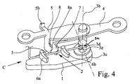
図1〜図3並びに図4及び図5は、自動車用錠の2つの実施例を示しており、該自動車用錠は、複数の施錠要素(係止要素又はロックエレメント)、つまり受座及び掛け金1を有している。自動車用錠は更にロック機構2を含んでおり、該ロック機構は種々の機能状態、例えば「施錠」、「解錠」、「盗難防止ロック」若しくは「チャイルドロック」に移されるようになっている。ロック機構2は、掛け金1を機能状態に依存して外側ノブ及び/又は内側ノブの操作によって解錠位置へ作動させ、或いは解錠位置へ全く作動できないように、構成されている。電動錠若しくは電動ロックの場合には、ロック機構2は、非常操作装置と掛け金1との連結のために用いられるものである。このようにロック機構なる用語は、広い意味で用いられているものである。
1-3 and FIGS. 4 and 5 show two embodiments of an automobile lock, which comprises a plurality of locking elements (locking elements or locking elements), i.e. a seat and a latch. 1 The car lock further includes a
上記機能状態へのロック機構2の操作のために、ロック機構2は、所定の機能位置(作動位置)へ作動可能な少なくとも1つの機能要素3を有している。機能要素3の作動により、ロック機構2は所望の機能状態へ移されるようになっている。
In order to operate the
原理的には、ロック機構2の機能状態の達成のために、複数の作動要素若しくは機能要素3を設けてあってよい。以下において、唯一の機能要素3を有する実施形態について述べるものの、これに本発明は限定されるものではない。
In principle, a plurality of actuating elements or
機能要素3は、機能要素3の1つの部分領域でのみ、図示のように有利には1つの端部領域でのみ支承装置3aを用いて次のように支承されており、つまり、機能要素3は支承されている部分以外では、予め規定された1つの基準面Rを基準として側方(水平方向)へも高さ方向(垂直方向又は上下方向)へも、機能要素の長手方向(延在方向)に対してほぼ垂直に作動可能になっている。基準面Rは、高さ方向作動(高さ方向の作動)と側方作動(側方の作動)の説明のためのみに用いられているものである。機能要素3の高さ方向作動は、機能要素3と基準面Rとの間の間隔の変化を伴って行われる。これに対して、機能要素3の側方作動は、機能要素3の、基準面Rに対してほぼ平行な作動(移動運動)である。高さ方向作動と側方作動とは、基準面Rに対して斜めの方向(高さ方向と側方との間の任意の角度により規定される方向)の作動を得るために、重畳されてよいものである。
The
基準面Rは任意の方向に向けられていてよいものである。しかしながら特に有利な図示の実施形態では、基準面Rは、自動車用錠の鍵座面若しくは広幅面に対してほぼ平行に向けられている。もちろん原理的には、機能要素の作動の方向を説明するために用いられる基準面は、自動車用錠の鍵座面若しくは広幅面に対してほぼ垂直に向けられていてよいものである。 The reference plane R may be directed in an arbitrary direction. However, in the particularly advantageous illustrated embodiment, the reference surface R is oriented substantially parallel to the key seat surface or wide surface of the automobile lock. Of course, in principle, the reference surface used to describe the direction of operation of the functional element may be oriented substantially perpendicular to the key seat surface or wide surface of the automobile lock.
機能要素3は、図示の実施形態によればレバー状の機能要素である。このことは、機能要素3が任意の形式で旋回可能に支承されていて、1つのてこ腕を有しており、該てこ腕が機能要素3の長さを規定していることを意味している。
The
図示の有利な実施形態では、機能要素3は、予荷重(初期荷重若しくは初期応力又はプレストレス)を受けた状態で、図1に示す出発位置(基準位置又は開始位置)を占めている。予荷重により、機能要素3は常に自動的に出発位置に戻されるようになっている。このような構成により、機能要素3の作動のために、機能要素3の適切な1つの支持部だけしか必要としていない。
In the advantageous embodiment shown, the
機能要素3の高さ方向作動及び側方作動は、有利には機能要素3の各1つの旋回運動に基づき行われるようになっている。しかしながら原理的には、機能要素3の高さ方向作動か、若しくは側方作動かを、有利には機能要素3の1つの旋回運動に基づき行うようにすることもできる。各旋回運動にそれぞれ幾何学的な1つの旋回軸3b,3cが属しており、該旋回軸は、機能要素3の1つの端部領域を通って延びている。
The height direction operation and the lateral operation of the
支承装置3aの構成については多くの実施形態が考えられる。例えば1つの実施形態として、支承装置3aは1つの弾性的な支承要素を有しており、該支承要素は、一方では、錠ハウジング等に固定され、若しくは錠ハウジング等に結合され、或いは錠ハウジング等に一体成形されており、かつ他方では機能要素3に結合されている。
Many embodiments are conceivable for the configuration of the
考えられる別の実施形態では、支承装置3aは弾性的な領域或いはゴム状の領域を有しており、該領域内に機能要素3が差し込まれている。
In another possible embodiment, the
しかしながら有利な実施形態によれば、支承装置3aは、相互に支承された状態で係合する2つの支承要素を有している。該実施形態において有利には、一方の支承要素は固定されており、他方の支承要素は、機能要素3に連結され、若しくは結合されている。機能要素3の作動に際して、両方の支承要素間には摩擦若しくは滑り摩擦が発生するようになっている。
However, according to an advantageous embodiment, the
特に有利な実施形態によれば、支承装置3aは、少なくとも一部分を滑り支承部の形式で形成されている。このような実施形態に、高さ方向作動及び/又は側方作動に際して相互に滑る複数の構成部分を有する全ての構成は含まれる。有利には、支承装置3aは純然たる滑り支承部として形成されている。
According to a particularly advantageous embodiment, the
特に有利な実施形態によれば、機能要素3の支承装置3aは、高さ方向作動のための第1の旋回支承部と側方作動のための第2の旋回支承部とを備えて構成されており、該両方の旋回支承部は、有利には機能要素3の1つの端部領域に配置されている。特にコンパクトな構成は、両方の旋回支承部をカルダンジョイントとして形成することによって得られる。
According to a particularly advantageous embodiment, the
有利な別の実施形態によれば、支承装置3aは、より簡単かつコンパクトな構造を得るために、球体と球面ソケットとから成る支承部(ボールソケットベアリング)を用いて形成されている。このような構成は、図示の全ての実施形態に設けられている。支承装置3aには、球面ソケット3d及び、該球面ソケット3dに係合している球体3eが配設されている。図示の有利な実施形態によれば、球体3eは、機能要素3の一方の端部に配置されているのに対して、球面ソケット3dは、不動に構成され、有利には自動車用錠のハウジングに配置されている。
According to another advantageous embodiment, the
機能要素3の作動は、原理的には、旋回運動のほかに、直線運動をも含むものである。このために、有利な実施形態によれば、支承装置3aは、特に高さ方向作動のために直線案内部(リニアガイド)を有している。
The operation of the
全ての実施形態において、支承装置3aは、機能要素3の構成部分又は構成成分ではない。つまり、支承装置3aの支承機能は、機能要素3の弾性作用に依存するものではない。すなわち、支承装置3aは独立の構成要素である。
In all the embodiments, the
更に述べれば、支承装置3aの支承機能は、機能要素3の基本形に相当する基本形を有する構成成分に依存するものではない。例えば、機能要素3を線材(ワイヤ)若しくは帯材(ストリップ[strjp])によって構成してある場合に、支承装置3aの支承機能は、線材若しくは帯材を曲げて成形されるばね等により形成されるものではない。このことから、支承装置3aの独立性が明確に理解されるものである。
More specifically, the support function of the
一般的な構成において、支承装置3aの支承機能は、ばね弾性の線材若しくは帯材の弾性作用により形成されるものではない。
In a general configuration, the support function of the
機能要素3を構成するために、種々の実施形態が考えられる。有利な実施形態によれば、機能要素3は長尺形状若しくは細長い形状を有している。長尺形状若しくは細長い形状の実施形態において、機能要素3は、剛直に形成され、すなわち高い曲げ強度を有し、更に有利には非弾性に、つまり、たわまないように形成され、特に有利には剛性に形成されている。
Various embodiments are conceivable for configuring the
機能要素3の特にコンパクトな構成は、機能要素3をロッド状若しくはワイヤ状に形成することにより得られる。
A particularly compact configuration of the
有利には、機能要素3は円形の横断面を有している。製作技術的な観点から有利には、機能要素3は、バンド状若しくはストリップ状に形成されており、バンド状若しくはストリップ状の部材は容易に取り付けられ得るものである。
Advantageously, the
図示の有利な実施形態によれば、機能要素3は、区分毎に直線的に形成されている。使用例に対応して、機能要素3は、構造条件に適合され、直線と異なる形状で形成されてよいものである。
According to the advantageous embodiment shown, the
機能要素3に対する機械的な負荷に対応して、機能要素3は、有利には金属材料若しくはプラスチック材料から成っている。
Corresponding to the mechanical load on the
ロック機構2は、周知のように、旋回可能な外側操作レバー4、及び必要に応じて旋回可能な内側操作レバー5(図4等)を有している。重要なことは、ロック機構2が、機能要素3の高さ方向作動(調節)により、所定の機能状態、有利には「解錠」機能状態又は「施錠」機能状態に移され、更に有利には「盗難防止ロック」機能状態に移され、更に有利には「チャイルドロック」機能状態に移されるようになっていることである。前記機能状態への作動(操作又は調節)のために、原理的には複数の機能要素3を設けることも可能である。
As is well known, the
ロック機構2の機能状態を達成するために、機能要素3は、有利には、ロック機構2の操作要素1,4,5間の切り換え可能なカップリングを形成している。該カップリング(連結部分又は連結器若しくは継手)は、図示の実施形態によれば、一方の操作要素である掛け金1と他方の操作要素である外側操作レバー4及び/又は内側操作レバー5との間のカップリングである。図1〜図3は、特定の使用例では有利に用いられる内側操作レバー5を備えない実施形態を示している。
In order to achieve the functional state of the
特に有利な実施形態によれば、機能要素3は、第1の機能位置(図1及び図4)で上述の操作要素1,4,5に直接に係合していて、言い換えれば、第1の機能位置へ移されて、操作要素1,4,5を互いに連結(カップリング)している。第2の機能位置においては、機能要素3は、少なくとも1つの操作要素1,4,5に対して係合解除され、ひいては操作要素1,4,5の相互の連結を解除(デカップル[decouple])している。機能要素と操作要素との間の上記係合は、図示の実施形態では直接的な係合であるものの、中間レバー等を介在させた間接的な係合であってもよいものである。機能要素3は、更に連結力のための伝達部材としても用いられている。機能要素3を介して伝達される力は、有利には、機能要素3の長手方向(延在方向)に対して垂直に作用している。機能要素3のロッド状若しくはワイヤ状の実施形態においては、連結力は、有利には機能要素3のロッド状若しくはワイヤ状の区分に対して垂直に作用している。
According to a particularly advantageous embodiment, the
ロック機構2の、図1及び図4に示す機能状態において、外側操作レバー4及び/又は図4の実施形態に設けられている内側操作レバー5の操作は、機能要素3による上述の連結機能(カップリング機能)に基づき、掛け金1のリフトオフ(解錠行程運動、つまり引き入れ行程運動)をもたらすものである。図面及び後の記載から明らかなように、掛け金1のリフトオフは、機能要素3の側方作動を伴って行われるものである。
In the functional state shown in FIGS. 1 and 4 of the
特に有利な実施形態によれば、機能要素3は、掛け金1の旋回軸に対してほぼ半径方向に向けられている。このことは、機能要素3が相応に半径方向に延びていることを意味している。しかも、機能要素3は、図示の有利な実施形態によれば、ほぼ掛け金1に沿って延びている。機能要素を半径方向に向けること、つまり機能要素の半径方向配置は、原理的には外側操作レバー4若しくは内側操作レバー5の旋回軸を基準として行われてよいものである。しかしながら、図示の有利な実施形態において両者間に差異はなく、それというのは、掛け金1、外側操作レバー4及び内側操作レバー5は、同一の旋回軸を中心として旋回可能になっているからである。図示の実施形態の配置構成により、高いコンパクト化を達成している。上述の意味の旋回軸は、具体的(物理的)な旋回軸(旋回シャフト)であり、或いは幾何学的な旋回軸(旋回軸線)である。
According to a particularly advantageous embodiment, the
外側操作レバー4と掛け金1との間の上述のカップリングを形成するために、有利な実施形態によれば、掛け金1が、或いは掛け金1に連結されたレバーが、掛け金・連行体輪郭部6を有しており、外側操作レバー4が、或いは外側操作レバー4に連結されたレバーが、外側操作レバー・連行体輪郭部7を有している。このような構成により、図示の実施形態では、機能要素を「解錠」機能位置に移してある場合に、外側操作レバー4は、外側操作レバー・連結体7、機能要素3及び掛け金・連行体輪郭部6を介して掛け金1に連結されている。該機能位置は、図1及び図4から極めて明瞭に見て取れる。
In order to form the above-described coupling between the
有利には、「施錠」機能状態では、機能要素3は、掛け金・連行体輪郭部6及び外側操作レバー・連行体輪郭部7から係合解除されており、その結果、外側操作レバー4は掛け金1から分離(デカップル)されている。「施錠」機能位置は、図2に鎖線で示してある。
Advantageously, in the “locked” function state, the
「施錠」機能位置は、機能要素3を両方の連行体輪郭部6,7のうちの一方から係合解除するだけでも達成される。
The “locking” functional position is also achieved by simply disengaging the
図1から見て取れるように、外側操作レバー4の旋回運動が、上方から見て左側へ、つまり反時計回りに行われると、外側操作レバー・連行体輪郭部7が、機能要素3に係合して、力を機能要素3の係合部位に、それも機能要素3の長手方向に対して垂直に作用させることになる。これによって、機能要素3は掛け金・連行体輪郭部6に作用し、結果として、掛け金1が作動され、つまりリフトオフされる。
As can be seen from FIG. 1, when the turning motion of the
連行体輪郭部6,7の構成について、有利な種々の実施形態が考えられる。図示の有利な実施形態によれば、掛け金・連行体輪郭部6は、2つの支持突起部6a,6bから成っており、該支持突起部(支承突起部)間を、外側操作レバー・連行体輪郭部7は、「施錠」機能位置では通過するようになっている。このような構成の利点は、機能要素3が、操作力(連結力)を伝達する、つまり受け止める係合部位で最適に支持されることにある。
Various advantageous embodiments are conceivable for the configuration of the entrained
別の有利な実施形態によれば、掛け金・連行体輪郭部6は、1つのスリットのみを有しており、該スリット内を、外側操作レバー・連行体輪郭部7が、「施錠」機能位置で通過するようになっている。「解錠」機能位置では、スリットは、「解錠」機能位置へ移された機能要素3によって遮断されるようになっている。
According to another advantageous embodiment, the latch /
両方の連行体輪郭部6,7を相互に交換することもできる。このことは、前述の支持突起部6a,6b若しくはスリットを外側操作レバー4に配置することもできることを意味している。
Both entrained
図4及び図5に示してある別の有利な実施形態によれば、外側操作レバー4に加えて、内側操作レバー5を追加的に設けてある。このような構成に対応して、内側操作レバー5は、或いは該内側操作レバー5に連結されているレバーは、内側操作レバー・連行体輪郭部8を有している。機能要素3を「解錠」機能位置へ移してある場合には、内側操作レバー5は、内側操作レバー・連行体輪郭部8、機能要素3及び掛け金・連行体輪郭部6を介して掛け金1に連結されている。つまり、掛け金1は内側操作レバー5によりリフトオフされ得るようになっている。これに対して、機能要素3は、「施錠」機能位置では、掛け金・連行体輪郭部6及び内側操作レバー・連行体輪郭部8から係合解除されており、結果として、内側操作レバー5が掛け金1から分離(連結解除)されている。機能要素3は、両方の連行体輪郭部6,8のうちの一方から係合解除されるだけでもよい。
According to another advantageous embodiment shown in FIGS. 4 and 5, in addition to the
「施錠」機能位置において、内側操作レバー5の操作により、掛け金1をリフトオフするために、有利な実施形態において、内側操作レバー5の操作が、ロック機構2を「施錠」機能状態から「解錠」機能状態に移して、解錠過程を実施することになる。
In order to lift off the
解錠過程にとって重要なことは、内側操作レバー5の操作に関連して自由移動距離を設けてあることであり、解錠過程は、自由移動距離(無作用距離)にわたる移動に際して行われる。自由移動距離は、内側操作レバー・連行体輪郭部8を非操作状態において機能要素3から所定の自由移動間隔9にわたって離間することによって設けられている。
What is important for the unlocking process is that a free movement distance is provided in relation to the operation of the
自由移動距離を有する有利な実施形態によれば、「施錠」機能位置において、内側操作レバー5の旋回は、まず(図1〜図5には示されていない何らかの方法で)解錠過程を行うことになり、機能要素3は、変位されていた位置から図4に示す位置へ降下するようになっている。次いで内側操作レバー5の引き続く旋回により、掛け金1のリフトオフが行われる。
According to an advantageous embodiment with a free movement distance, in the “locking” function position, the pivoting of the
原理的には、「施錠」機能位置において、内側操作レバー5の二回の旋回を必要とするようにすることも可能である。このような操作は、一般的にダブルストローク・タクシー機能(double-stroke taxi function)と称されている。このような変化例も容易に実施されるものである。つまり、内側操作レバー5の一回目の旋回に際して、機能要素3は、内側操作レバー・連行体輪郭部8の図4及び図5に示してある肩部8a上に降下することになる。肩部上に機能要素3は、内側操作レバー5が後退旋回されるまで維持され、次いで内側操作レバー5は二回目に解錠旋回される。
In principle, it is possible to require two turns of the
機能要素3の制御に基づく高さ方向作動のために、1つの制御駆動部10を設けてある。該駆動部には、原理的には、作動すべき複数の機能要素3若しくは別の従来構造の複数の機能要素3が配設されるようになっていてよいものである。配設の機能要素3は、制御駆動部10の駆動により相応に幾つかの機能位置へ作動可能になっている。幾つかの機能位置は、機能要素3のばね弾性作用に基づく戻り運動によって達成される。制御駆動部10の有利な2つの実施形態を、図6及び図7並びに図8及び図9に概略的に示してある。
One
図示の有利な両方の実施形態において、制御駆動部10は制御シャフト11を含んでおり、該制御シャフトに、配設の機能要素3が支えられており、その結果、制御シャフト11の作動(回転)により機能要素3は高さ方向で変位させられるようになっている。特に有利な実施形態によれば、機能要素3は、制御シャフト軸線12に対してほぼ垂直に延びている。
In both the preferred embodiments shown, the
有利には、制御駆動部10はモータ式の制御駆動部10である。つまり、制御シャフト11は、図示してあるように、駆動モータ13に連結されている。図示の実施形態によれば、制御シャフト11は、駆動モータ13のモータシャフト14に直接に配置されるようになっている。考えられる実施形態によれば、制御シャフト11は小歯車等を介してモータシャフトに駆動可能に連結されている。
Advantageously, the
制御駆動部10は、手動により作動されるように構成されていてもよいものである。このような実施形態では、制御駆動部10は、適切な手動式の操作要素に連結され、例えば錠シリンダ若しくは内部ロックノブに連結されている。
The
制御シャフト11は、モータ駆動により若しくは手動操作により、「解錠」制御位置又は「施錠」制御位置へ作動され得るものである。これにより、制御シャフト11は機能要素3を、「施錠」機能位置へ移し、或いは「解錠」機能位置へ戻すことになる。
The
図示の実施形態によれば、制御シャフト11は、カムを有するカムシャフトとして形成されており、配設の機能要素3はカムシャフトに支えられていて、カムシャフトの作動により相応に変位させられるようになっている。このことは図7に示してある。
According to the illustrated embodiment, the
図7において、a)は、図1及び図4に示された状態に相当する「解錠」機能位置を示している。図7のb)は、制御シャフト11の第1の作動、つまり、図7で左回り(逆時計回り)の回転を示しており、該作動は機能要素3の作動を伴わないものであり、これにより駆動モータの安価な構成が可能になっている。制御シャフト11の引き続く作動に際して、制御シャフト11に設けられたカム11aが、機能要素3を図7で上方へ変位(作動、上方旋回)させている(図7のc)。該変位位置(上方変位)は、「施錠」機能位置に相当している。機能要素3の該機能位置は、図2に鎖線で描かれている。図6及び図7から見て取れるように、機能要素3の作動は、制御シャフト11を用いて構造的に特に簡単に実施されるものである。
In FIG. 7, a) shows the “unlocking” functional position corresponding to the state shown in FIGS. FIG. 7 b) shows the first operation of the
制御シャフト11をカムシャフトとして形成する実施形態とは異なる別の有利な実施形態によれば、制御シャフト11は、クランクの形状をしたクランクシャフトとして形成されている。該実施形態の場合には、配設の機能要素3はクランクシャフトに支えられ、より厳密にはクランクシャフトの偏心的な区分に支えられている。特に製作技術的な利点が、制御シャフト11を、屈曲された線材によって形成することにより得られる。特にコンパクトな構成を得るために、有利な実施形態によれば、制御シャフト11は同時に駆動モータ13のモータシャフト14である、つまり、制御シャフト11は、駆動モータ13のモータシャフト14自体によって形成されている。
According to another advantageous embodiment, which differs from the embodiment in which the
既に述べてあるように、「施錠」機能状態において、内側操作レバー5の操作により、解錠過程を実施することができる。このために、図6及び図7並びに図8及び図9に示してある有利な実施形態によれば、制御シャフト11は、オーバライド輪郭部11bを有している。オーバライド輪郭部11bに対応して、図4及び図5に示してある内側操作レバー5に設けられた別のオーバライド輪郭部5b若しくは、内側操作レバー5と連結されたレバーに設けられた別のオーバライド輪郭部が配置されている。
As already described, the unlocking process can be performed by operating the
「施錠」機能状態(図7c)において、内側操作レバー5の操作により、内側操作レバー側のオーバライド輪郭部5bは、制御シャフト側のオーバライド輪郭部11bに係合して、制御シャフト11を「解錠」制御位置(図7a)へ移すことになる。これにより、機能要素3が相応に、「解錠」機能位置に移され、結果として、ロック機構2が「解錠」機能状態に移される。このような解錠過程の実施のために、他の変化例も考えられる。
In the “locked” function state (FIG. 7 c), by operating the
制御シャフト11の位置決めは、有利には制止手段によって行われる。図6及び図7に示す実施形態によれば、「解錠」制御位置から「施錠」制御位置への制御シャフト11の作動中に、オーバライド輪郭部11bは、制止要素15に向かって移動するようになっている。「解錠」制御位置への制御シャフト11の戻りは、同じく制止手段によって行われるようになっていてよいものである。このために制御手段を用いることも考えられる。
The positioning of the
図8及び図9に示す実施形態は、図6及び図7に示してある実施形態に改良を加えて、「盗難防止ロック」機能状態を実施できるように有利に変更されたものである。制御シャフト11が「盗難防止ロック」制御位置へ移されるようになっており、「盗難防止ロック」制御位置は、まず機能要素3の作動に基づき「施錠」位置に相当するものである。更に制御シャフト11は、「盗難防止ロック」制御位置において、制御シャフト側のオーバライド輪郭部11bが内側操作レバー側のオーバライド輪郭部5bの運動領域16の外側にあるように、位置決めされている。
The embodiment shown in FIGS. 8 and 9 is an advantageous modification to the embodiment shown in FIGS. 6 and 7 to improve the “anti-theft lock” functional state. The
図9は、上述の有利な実施形態の種々の制御位置を示している。図9のa)は、解錠された状態を示しており、該状態では、既に述べてあるように、機能要素3は変位させられていない。これに対して、図9のb)は、「施錠」制御位置を示しており、該制御位置では、機能要素3は変位させられており、制御シャフト側のオーバライド輪郭部11bは、内側操作レバー側のオーバライド輪郭部5bの運動領域16内にある。図9のc)は、「解錠」制御位置と「施錠」制御位置との間の中間状態を示している。図9のd)は、「盗難防止ロック」制御位置を示している。図9のb)とd)とを見比べることにより明らかであるように、「施錠」制御位置及び「盗難防止ロック」制御位置において機能要素3の変位が行われていて、有利には同じである。
FIG. 9 shows various control positions of the advantageous embodiment described above. FIG. 9 a) shows the unlocked state, in which the
図9のd)に示してある「盗難防止ロック」制御位置において重要なことは、制御シャフト側のオーバライド輪郭部11bが、内側操作レバー側のオーバライド輪郭部5bの運動領域16の外側にあることである。これによって、「盗難防止ロック」制御位置においては内側操作レバー5によっても掛け金1のリフトオフを不可能にすることが保証されている。
What is important in the “anti-theft lock” control position shown in FIG. 9d) is that the
図8及び図9に示してある実施形態の場合にも、制御シャフト11の制御は、少なくとも部分的には制止手段を用いて行われている。このような制御には、「施錠」制御位置(図9のb)及び「盗難防止ロック」(図9のd)が含まれる。このために、制御シャフト11が制止輪郭部11cを有しており、該制止輪郭部(制止用成形部又は制止突起部)は、制止要素17と係合するようになっている。該実施形態においては、制止要素(ブロッキング・エレメント[blocking element])17は、作動可能(調節可能)に形成されていて、「施錠」制御位置(図9のb)又は「盗難防止ロック」(図9のd)に移されるようになっている。制止要素17の作動のために別の駆動モータ18を設けてある。原理的には、制止要素17の手動操作も可能である。制止要素17は、駆動モータ18のモータシャフト19に直接配置されている。原理的に考えられる別の実施形態によれば、制止要素17は、小歯車等を介して駆動モータ18に駆動可能に連結され、つまり駆動結合されている。
In the case of the embodiment shown in FIGS. 8 and 9 as well, the control of the
制止要素17の作動により、制御シャフト11の種々の制止位置が得られるようになっている。制止要素17を「施錠」制止位置へ作動させると、制御シャフト11は「施錠」制御位置(図9のb)に制止(ブロッキング又はロック)される。制止要素17を「盗難防止ロック」制止位置へ作動させると、制御シャフト11は「盗難防止ロック」制御位置(図9のd)に制止される。つまり、制止要素17は、盗難防止ロックレバーの機能を有しており、駆動モータ18は盗難防止ロックモータの機能を有している。
Various stop positions of the
制御シャフト11は、図8及び図9に示してある有利な実施形態においては、更にエジェクタ輪郭部11dを備えており、該エジェクタ輪郭部(エジェクタ用成形部又はエジェクタ突起部)は、「盗難防止ロック」制御位置(図9のd)から「解錠」制御位置(図9のa)への制御シャフト11の作動に際して、制止要素17と係合して、制止要素17を「施錠」制止位置へ移すようになっている。このような機能は、駆動モータ(盗難防止ロックモータ)18が故障した際に、例えばロックシリンダーを介して手動解錠を行う場合に、有利に用いられるものである。
In the advantageous embodiment shown in FIGS. 8 and 9, the
付言すれば、上述の機能要素3は、配設された操作要素1,4,5の1つに、有利には掛け金1、外側操作レバー4若しくは内側操作レバー5と次のように連結されており、つまり、機能要素3、連結された操作要素1,4,5に予荷重(プロストレス)を掛けている。機能要素3のこのような二重機能は、前に掛け金ばね、外側操作レバー若しくは内側操作レバーと関連して述べてある。
In other words, the above-described
本発明に基づく自動車用錠を用いて、「チャイルドロック」機能状態を達成することができる。有利な変化例によれば、別の機能要素3を設けてあり、該機能要素は、同じく制御駆動部10によって作動されるようになっている。
With the car lock according to the invention, a “child lock” functional state can be achieved. According to an advantageous variant, another
図10〜図13は、本発明に基づく自動車用錠の別の実施形態を示しており、該実施形態は、原理的には、図4及び図5若しくは図6〜図9に示す自動車用錠の実施形態と類似して形成されているものである。図面には、前に述べられていて制御シャフト11に対応して配置(配設)される受座も描かれて、符号1aを付けられている。該実施形態にも設けられているロック機構2は、外側操作レバー4(図13には描かれていない)及び内側操作レバー5を有している。更に、前記形式の機能要素3を設けてあり、該機能要素は、種々の機能位置へ作動させられるようになっている。
10 to 13 show another embodiment of the automobile lock according to the present invention, which in principle is the automobile lock shown in FIG. 4 and FIG. 5 or FIG. 6 to FIG. It is formed similar to the embodiment. The drawing also shows a seat which has been previously described and is arranged (arranged) corresponding to the
図10〜図13に示す実施形態においても、駆動部10及び制御シャフト11を設けてあり、該制御シャフトに配設の機能要素3が支えられている。制御シャフト11は、同様に前記形式のオーバライド輪郭部11bを備えていて、しかも、「解錠」及び「施錠」制御位置にだけではなく、「盗難防止ロック」制御位置へも移されるようになっており、該「盗難防止ロック」制御位置ではオーバライド輪郭部11bは非作用状態にされている。「盗難防止ロック」制御位置(図12)は、ここでも制止手段を用いて得られるようになっている。
Also in the embodiment shown in FIGS. 10 to 13, the
図10は、機能要素3が有利には変位されていない「解錠」機能状態を示している。図面から見て取れるように、外側操作レバー4は、外側操作レバー・連行体輪郭部7を介して掛け金1に連結され、かつ内側操作レバー5は、内側操作レバー・連行体輪郭部8、更に機能要素3及び掛け金・連行体輪郭部6を介して、掛け金1に連結されている。
FIG. 10 shows the “unlocking” functional state in which the
図11及び図13は、「施錠」機能状態を示している。該機能状態では、機能要素3は、該機能要素3が外側操作レバー・連行体輪郭部7及び内側操作レバー・連行体輪郭部8から係合解除されるように、変位され、図面で上方作動又は上方旋回されている。内側操作レバー5の作動(操作)は、「解錠」機能位置への機能要素3の作動を生ぜしめている。
11 and 13 show the “locking” function state. In this functional state, the
図12は、「盗難防止ロック」機能状態を示しており、該機能状態は、「施錠」機能状態と異なっており、つまり、制御シャフト側のオーバライド輪郭部11bは、内側操作レバー側のオーバライド輪郭部5bの運動領域の外側へ回動させられている。
FIG. 12 shows the “anti-theft lock” function state, which is different from the “locking” function state. That is, the
図10〜図13に示してある実施形態において、特徴が外側操作レバー・連行体輪郭部7及び内側操作レバー・連行体輪郭部8の構成にある。外側操作レバー・連行体輪郭部7及び内側操作レバー・連行体輪郭部8は、条片状若しくは舌片状に形成されていて、外側操作レバー4若しくは内側操作レバー5の旋回軸を中心とする仮想の円の円弧に沿って延びている。図13からは、内側操作レバー・連行体輪郭部8が明確に見て取れる。更に該実施態様では、外側操作レバー・連行体輪郭部7と内側操作レバー・連行体輪郭部8とは、互いに隣接して並んで延びている。このような構成により、特にコンパクトな配置が可能である。上記構成は、一方の連行体輪郭部7,8にしか設けられていなくてもよいものである。
In the embodiment shown in FIGS. 10 to 13, the feature is the configuration of the outer operation lever / entraining
図示の有利な全ての実施形態において、掛け金・連行体輪郭部6、外側操作レバー・連行体輪郭部7及び内側操作レバー・連行体輪郭部8は、掛け金1、若しくは外側操作レバー4、或いは内側操作レバー5の旋回軸に対してほぼ平行に延びている。このような構成も、原理的には連行体輪郭部6,7,8の1つにしか設けられていなくてもよいものである。連行体輪郭部6,7,8は、互いに異なる高さに配置されていてよいものである。
In all the preferred embodiments shown, the latch /
図10〜図13に示してある実施形態において、別の特徴が制御シャフト側のオーバライド輪郭部11bの構成にある。内側操作レバー側のオーバライド輪郭部5bと協働する制御シャフト側のオーバライド輪郭部11bは、次のように構成されており、つまり、「施錠」機能状態において、内側操作レバー5の操作により、内側操作レバー側のオーバライド輪郭部5bが、制御シャフトのシャフト軸12に対してほぼ平行に移動し、制御シャフト側のオーバライド輪郭部11bを介して制御シャフト11を「解錠」位置へ移すようになっている。制御シャフト側のオーバライド輪郭部11bは、有利には、シャフト軸12に沿って延びる傾斜部として形成され、特に有利にはシャフト軸12に対してねじ山状若しくはウォーム状に延びる隆起部として形成されている。図13は、内側操作レバー側のオーバライド輪郭部5bが、内側操作レバー5の作動中に制御シャフト側のオーバライド輪郭部11bとちょうど係合した状態を示している。
In the embodiment shown in FIGS. 10 to 13, another feature is the configuration of the
図10〜図13に示してある実施形態において、更なる特徴が制御シャフト11のカム11aの構成にある。カム11aは、「解錠」、「施錠」及び「盗難防止ロック」の各制御位置にとって、機能要素3の予荷重(初期荷重若しくは初期応力又はプレストレス)に基づきそれぞれ安定状態が得られるように形成されている。このような構成においては、1つの制御位置から別の次の制御位置への制御シャフト11の作動(回動)に際してその都度、機能要素3の大きな変位を生ぜしめることになる。このことは、カム11aに適切なエッジ(稜線縁部)21,22を設けることによって実施されるものである。このような手段により、機能要素3の予荷重は、カム11aの上述の構成と相俟って制御シャフト11を各制御位置に保持するように働くことになる。
In the embodiment shown in FIGS. 10 to 13, a further feature is the configuration of the
図10〜図13に示してある実施形態においても、制御シャフト11は、制止要素17と係合可能な制止輪郭部11cを有している。制御シャフト11及び制止要素17は、有利には動力により作動されるようになっている。このために有利には2つの駆動モータ(図示省略)を設けてあり、該駆動モータの駆動シャフトは、有利には制御シャフトのシャフト軸12に対して平行に向けられている。
Also in the embodiment shown in FIGS. 10 to 13, the
制止要素17は、制御シャフト11をまず「施錠」制御位置で制止するために、制止輪郭部11cと係合するようになっている。制御シャフト11を「盗難防止ロック」制御位置へ作動させるために、制止要素17は、制止輪郭部11cの開口状の切欠き部内へ入り込まされる。更に、制御シャフト11が「盗難防止ロック」制御位置に向けて作動され、これによって制止要素17が、制止輪郭部11cの開口状の切欠き部内でかしがれて、該切欠き部内の相対する部位間に締め付けられ、つまりロックされ、ひいては制御シャフト11の引き続く作動を制止するようになっている。
The
制御シャフト11の制止輪郭部11cの開口状の切欠き部の構成により、制止のための追加的なストッパーは省略されるようになっている。
Due to the configuration of the opening-shaped notch portion of the restraining
上記開口状の切欠き部の構成は、更なる利点を有し、つまり、図8及び図9の実施形態で述べてあるエジェクタ輪郭部11dをも形成するものであり、該エジェクタ輪郭部は、「盗難防止ロック」制御位置(図12)から「解錠」制御位置(図10)への制御シャフト11の手動操作に際して、制止要素17を「施錠」制止位置へ移すようになっている。
The configuration of the opening-shaped notch has a further advantage, that is, it also forms the
付言すれば、「盗難防止ロック」制御位置では、オーバライド輪郭部11bは、内側操作レバー側のオーバライド輪郭部5bの運動領域から外側へ回動旋回させられている。このような作動過程は、図4乃至図9に示す実施形態の作動過程にほぼ相当するものである。
In other words, in the “anti-theft lock” control position, the
制御シャフト11のカム11aの構成は、該カムの側方に肩部23を配設して、該肩部によってカム11aからの側方(制御シャフトの軸線の方向)への機能要素3の滑り落ちを阻止することにより、有利に用いられるものである。
The
本発明に基づく自動車用錠には、容易にチャイルドロック機能を設けることができるものである。図14及び図15は、制御駆動部10の、チャイルドロック機能のために選ばれた構成要素、特に、自動車用錠の制御シャフト11を概略的に示しており、該自動車用錠の、制御シャフト以外の構成は、図10〜図13に示す実施形態のものに相当するものである。
The car lock according to the present invention can be easily provided with a child lock function. 14 and 15 schematically show the components of the control drive 10 selected for the child lock function, in particular the
図14及び図15に示してある制御シャフト11も、原理的には、図10〜図13に示してある制御シャフト11と同様に作動するものである。制御シャフト11は、機能要素3と係合するためのカム11aを備えている。オーバライド輪郭部11b及び制止輪郭部11cも原理的には設けられているものの、ここでは図示を省略してある。
The
図14及び図15に示す実施形態によれば、ロック機構2は、並列的に「チャイルドロック」機能状態に移され、これによって「解錠」機能位置が自動的に「解錠・チャイルドロック」機能位置に移行するようになっている。つまり、「解錠」制御位置への制御シャフト11の作動は、機能要素3を、「解錠」機能位置にではなく、「解錠・チャイルドロック」機能位置へ作動させることになる。
According to the embodiment shown in FIGS. 14 and 15, the
「解錠・チャイルドロック」機能位置では、内側操作レバー5は、掛け金1から連結解除されており、外側操作レバー4が掛け金1に連結されている。従って、ロック機構2において「チャイルドロック」機能状態では、解錠過程は、機能要素3を、自動的に「解錠・チャイルドロック」機能位置へ移すものである。有利には、「解錠・チャイルドロック」機能位置は、「解錠」機能位置と「施錠」機能位置との間にある。
In the “unlock / child lock” function position, the
機能要素3の「解錠・チャイルドロック」機能位置は、図15のc)に示してある。外側操作レバー・連行体輪郭部7及び内側操作レバー・連行体輪郭部8は、「解錠・チャイルドロック」機能位置では、機能要素3が、内側操作レバー・連行体輪郭部8から係合解除されており、内側操作レバー5が掛け金1から連結解除されており、かつ外側操作レバー4が、外側操作レバー・連行体輪郭部7、機能要素3及び掛け金・連行体輪郭部6を介して掛け金1に連結されているように、構成されている。両方の連行体輪郭部7,8の上述の選択的な連結は、機能要素3の変位方向で見て、外側操作レバー・連行体輪郭部7の延在長さを、内側操作レバー・連行体輪郭部8の延在長さよりも長くすることによって、つまり、外側操作レバー・連行体輪郭部7が、機能要素3の変位方向で内側操作レバー・連行体輪郭部8よりも長く延びていることによって実施されるようになっている。このような構成は、図15に明確に示されている。連行体輪郭部6,7,8は、図14には描かれていない。
The “unlock / child lock” functional position of the
図14及び図15は、「チャイルドロック」機能状態の達成のための特にコンパクトな構成を示している。コンパクトな構成のために、別の機能要素、つまり、それ自体作動可能なチャイルドロック要素20を設けてあり、該チャイルドロック要素は、「チャイルドロック」位置(図15のc)と「チャイルドロック解除」位置(図15のa及びb)との間で作動可能である。チャイルドロック要素20の作動は、「チャイルドロック」機能状態又は「チャイルドロック解除」機能状態の設定を意味するものである。
14 and 15 show a particularly compact arrangement for achieving the “child lock” functional state. For a compact construction, another functional element is provided, namely a
「チャイルドロック」機能状態では、チャイルドロック要素20は、「解錠」制御位置への制御シャフト11の作動に際して、機能要素3を、「解除」機能位置の前に設けられた「解錠・チャイルドロック」機能位置に維持している。このことは、「チャイルドロック」機能状態では、制御シャフト11を可能な全ての制御位置へ移すことができ、「解錠」制御位置の達成により、機能要素3が「解錠・チャイルドロック」機能位置に維持されることを意味している。
In the “child lock” function state, the
「施錠」制御位置へ制御シャフト11を作動させることにより、機能要素3は、チャイルドロックの掛けられている状態では、変更されることなく「施錠」機能位置へ移される。内側操作レバー5の操作は、オーバライド輪郭部11bを介して、解錠過程をも行うものである。しかしながら、該解錠過程において、機能要素3は再び、前側に設けられている「解錠・チャイルドロック」機能位置に移されることになり、従って、内側操作レバー5による掛け金1のリフトオフは、行われないようになっている。
By actuating the
チャイルドロック要素20の構成は、種々に実施可能である。有利な実施形態によれば、チャイルドロック要素20は、チャイルドロックシャフトとして形成されており、更に有利には、チャイルドロックシャフト20は、制御シャフトのシャフト軸12の方向に向けられている。特にコンパクトな配置のために、チャイルドロックシャフト20は少なくとも部分的に制御シャフト11内に組み込まれている。図示の実施形態によれば、チャイルドロックシャフト20は、完全に制御シャフト11内に組み込まれており、つまり、チャイルドロックシャフト20は、制御シャフト11の切欠き部(凹部)24内に配置されている。
The configuration of the
チャイルドロックシャフト20を機能要素3に係合させるために、有利な構成では、チャイルドロックシャフト20は、カムを有するカムシャフトとして形成されおり、配設の機能要素3がカムシャフトに支えられるようになっている。図14及び図15に示す特に有利な実施形態によれば、チャイルドロックシャフト20は、クランク状に屈曲されたクランクシャフトとして形成されており、配設の機能要素3は、クランクシャフト20に支えられている。クランクシャフト20が、係合区分20aを有しており、該係合区分が、機能要素3と係合するようになっている。チャイルドロックシャフト20は、製作技術的に有利には、一体に、特に、屈曲された線材等により形成されている。
In order to engage the
チャイルドロック要素20は、前に述べてあるように、「チャイルドロック」位置へ、或いは「チャイルドロック解除」位置へ移されるようになっている。このために、チャイルドロック要素20には作動区分20bを配設してあり、該作動区分を介してチャイルドロック要素20が作動されるようになっている。作動区分20bは、例えば、サイドドアの端面側からアクセス可能なチャイルドロックスイッチ若しくはチャイルドロック駆動部に連結されている。
The
更に図15から明らかなように、チャイルドロック要素20が「チャイルドロック解除」位置にある場合には、機能要素3の操作は阻止されない。機能要素3は、「解錠」機能位置(図15のa)、「施錠」機能位置(図15のb)、並びに図示省略の「盗難防止ロック」機能位置へ移され得るようになっている。このような操作は、図15のc)に示してあるように「チャイルドロック」機能位置を設定してある場合には行われない。ここでは、制御シャフト11は「解錠」制御位置にある。機能要素3は、「解錠」機能位置に移されるのではなく、チャイルドロック要素20によって自動的に「解錠・チャイルドロック」機能状態に保たれるようになっている。
Further, as is apparent from FIG. 15, when the
図示の全ての実施形態において、有利には、制御シャフト11は、できるだけ高い硬度を有するプラスチックから成っている。更に、機能要素3と制御シャフト11との間にできるだけわずかな摩擦しか発生させない材料が選ばれる。制御シャフト11は、錠溝又はロック溝若しくは錠孔等に適合された輪郭を有していてよいものである。
In all the illustrated embodiments, the
掛け金・連行体輪郭部6に2つ若しくは複数の支持突起部6a,6bを設けてある場合に、有利には、機能要素3の変位方向で見て、両方の支持突起部6a,6bの構成高さ(上下方向又は垂直方向の寸法)は互いに異なっている。有利には、支持突起部6a,6bの上面は、完全に上方へ変位させられた機能要素3に対してほぼ平行な直線の方向に向けられ、言い換えれば、該直線に平行な仮想の線に沿って延びている。
When two or
非常操作装置を用いる場合には、機能要素3は、常に非常操作レバーの運動領域に位置するようになっている。
When the emergency operation device is used, the
重要なことは、機能要素3が少なくとも部分的に、つまり所定の長さにわたってばね弾性的に形成され、特に、ばね弾性的にたわみ可能な線材若しくは帯材として形成されていることである。このような機能要素3の有利な構成は、独国特許出願公開第102008018500号明細書に記載してあり、該特許出願は、本出願人によるものであり、該明細書に記載の構成事項は、本発明の背景技術として用いられるものである。
What is important is that the
機能要素3は、付加的に該機能要素3の1つの部分領域、特に端部領域で支承装置3aによって支承されており、それも、機能要素3は、支承部以外、つまり支承された端部領域以外のところでは、前に述べてある基準面Rを基準として高さ方向か又は側方にはもっぱら支承装置3aだけを介して作動されるのに対して、側方か又は高さ方向にはもっぱら該機能要素3のばね弾性的なたわみに基づき作動されるようになっている。
The
実施形態の更なる改良が、線材状の機能要素3にあり、該機能要素は一方の端部を折り曲げられており、該折り曲げられた端部は、錠ハウジング内で自動車用錠の鍵面に対して垂直に設けられた孔内に差し込まれている。孔は支承装置3aを形成していて、機能要素3の側方の旋回を可能にするものである。機能要素3の高さ方向作動は、機能要素3のばね弾性的なたわみに基づき行われるものである。
A further improvement of the embodiment lies in the wire-like
これまで述べたように、機能要素3の高さ方向作動は、ロック機構2の相応の機能状態を達成するためのものであり、特に掛け金1のリフトオフが、機能要素3の側方作動によって行われる。
As described above, the height direction operation of the
1 掛け金、 1a 受座、 2 ロック機構、 3 機能要素、 3a 支承装置、 3b,3c 旋回軸、 3d 球面ソケット、 3e 球体、 4 外側操作レバー、 5 内側操作レバー、 5b オーバライド輪郭部、 6 掛け金・連行体輪郭部、 6a,6b 支持突起部、 7 外側操作レバー・連行体輪郭部、 8 内側操作レバー・連行体輪郭部、 8a 肩部、 9 自由移動間隔、 10 制御駆動部、 11 制御シャフト、 11a カム、 11b オーバライド輪郭部、 11c 制止輪郭部、 11d エジェクタ輪郭部、 12 シャフト軸、 13 駆動モータ、 14 モータシャフト、 15 制止要素、 16 運動領域、 17 制止要素、 18 駆動モータ、 19 モータシャフト、 20 チャイルドロック要素、 20a 係合区分、 20b 作動区分、 24 切欠き部、 R 基準面 1 latch, 1a seat, 2 lock mechanism, 3 functional element, 3a support device, 3b, 3c pivot shaft, 3d spherical socket, 3e spherical body, 4 outer operation lever, 5 inner operation lever, 5b override contour, 6 latch / Entrained body contour, 6a, 6b support protrusion, 7 outer operation lever / entrained body contour, 8 inner operation lever / entrained body contour, 8a shoulder, 9 free movement interval, 10 control drive, 11 control shaft, 11a cam, 11b override contour, 11c stop contour, 11d ejector contour, 12 shaft shaft, 13 drive motor, 14 motor shaft, 15 stop element, 16 motion region, 17 stop element, 18 drive motor, 19 motor shaft, 20 child lock elements, 20a Joint section, 20b operation section, 24 notch, R reference plane
Claims (18)
前記内側操作レバー(5)、若しくは該内側操作レバー(5)に連結されたレバーは、内側操作レバー・連行体輪郭部(8)を有しており、前記機能要素(3)を「解錠」機能位置に移してある場合に、前記内側操作レバー(5)は、前記内側操作レバー・連行体輪郭部(8)、前記機能要素(3)及び前記掛け金・連行体輪郭部(6)を介して、前記掛け金(1)に連結されており、「施錠」機能状態において、前記機能要素(3)は、前記掛け金・連行体輪郭部(6)及び/又は前記内側操作レバー・連行体輪郭部(8)から係合解除されており、かつ前記内側操作レバー(5)は、前記掛け金(1)から連結解除されている請求項9、11、13または15に記載の自動車用錠。 The latch (1) or the lever connected to the latch (1) has a latch / entrained body contour (6), and the outer operation lever (4) or the outer operation lever (4). The lever connected to the outer control lever / entrained body contour (7) has the outer control lever (4) when the functional element (3) is moved to the "unlocking" function position. ) Is connected to the latch (1) via the outer operation lever / entrained body contour portion (7), the functional element (3) and the latch / entrained body contour portion (6). In the functional state, the functional element (3) is disengaged from the latch / entrained body contour (6) and / or the outer operation lever / entrained body contour (7) and the outer operation The lever (4) is disconnected from the latch (1). ,
The inner control lever (5), or the lever coupled to the inner control lever (5) has inner operating lever entraining lug contour portion (8), "unlock the functional element (3) The inner operation lever (5) moves the inner operation lever / entrained body contour (8), the functional element (3) and the latch / entrained body contour (6) when moved to the functional position. through it, the is connected to the latch (1), in the "locked" functional state, said functional element (3), the latch-driving members contour portion (6) and / or the inner operating lever driving members contour The automobile lock according to claim 9, 11, 13, or 15 , wherein the engagement is released from the portion (8) and the inner operation lever (5) is released from the latch (1).
Applications Claiming Priority (3)
| Application Number | Priority Date | Filing Date | Title |
|---|---|---|---|
| DE200820012484 DE202008012484U1 (en) | 2008-09-21 | 2008-09-21 | Motor vehicle lock |
| DE202008012484.0 | 2008-09-21 | ||
| PCT/EP2009/006792 WO2010031580A1 (en) | 2008-09-21 | 2009-09-21 | Motor vehicle lock |
Publications (2)
| Publication Number | Publication Date |
|---|---|
| JP2012503120A JP2012503120A (en) | 2012-02-02 |
| JP5393794B2 true JP5393794B2 (en) | 2014-01-22 |
Family
ID=41319874
Family Applications (1)
| Application Number | Title | Priority Date | Filing Date |
|---|---|---|---|
| JP2011527254A Expired - Fee Related JP5393794B2 (en) | 2008-09-21 | 2009-09-21 | Car lock |
Country Status (12)
| Country | Link |
|---|---|
| US (1) | US9074393B2 (en) |
| EP (1) | EP2342405B1 (en) |
| JP (1) | JP5393794B2 (en) |
| KR (2) | KR20110056425A (en) |
| CN (1) | CN102224311B (en) |
| BR (1) | BRPI0920888A2 (en) |
| DE (1) | DE202008012484U1 (en) |
| ES (1) | ES2390251T3 (en) |
| MX (1) | MX354495B (en) |
| MY (1) | MY158690A (en) |
| WO (1) | WO2010031580A1 (en) |
| ZA (1) | ZA201101581B (en) |
Families Citing this family (30)
| Publication number | Priority date | Publication date | Assignee | Title |
|---|---|---|---|---|
| DE202009017667U1 (en) * | 2009-12-26 | 2011-05-05 | BROSE SCHLIEßSYSTEME GMBH & CO. KG | Motor vehicle lock arrangement |
| CN102654004B (en) * | 2011-03-02 | 2014-12-17 | 布罗斯锁闭系统有限责任两合公司 | Motor vehicle lock |
| DE102011018512A1 (en) * | 2011-04-23 | 2012-10-25 | Kiekert Ag | Motor vehicle door lock |
| DE102012003698A1 (en) * | 2012-02-28 | 2013-08-29 | BROSE SCHLIEßSYSTEME GMBH & CO. KG | Motor vehicle lock |
| SE537873C2 (en) * | 2012-07-17 | 2015-11-03 | Scania Cv Ab | Lock with control device |
| DE202012007312U1 (en) † | 2012-07-31 | 2013-11-04 | BROSE SCHLIEßSYSTEME GMBH & CO. KG | Motor vehicle lock arrangement |
| DE102012111298A1 (en) * | 2012-11-22 | 2014-05-22 | Kiekert Aktiengesellschaft | Motor vehicle door lock |
| CN104956019B (en) * | 2012-11-27 | 2017-06-27 | 麦格纳覆盖件有限公司 | For the closing breech lock of car door |
| US9732544B2 (en) | 2013-03-25 | 2017-08-15 | Brose Schliesssysteme Gmbh & Co. Kg | Motor vehicle lock |
| US9376842B2 (en) * | 2013-03-25 | 2016-06-28 | Brose Schliesssysteme Gmbh & Co. Kg | Motor vehicle lock |
| US9366063B2 (en) | 2013-03-25 | 2016-06-14 | Brose Schliesssysteme Gmbh & Co. Kg | Motor vehicle lock |
| DE202013004025U1 (en) | 2013-04-30 | 2014-08-01 | BROSE SCHLIEßSYSTEME GMBH & CO. KG | Motor vehicle lock |
| DE202013004026U1 (en) | 2013-04-30 | 2014-08-01 | BROSE SCHLIEßSYSTEME GMBH & CO. KG | Motor vehicle lock |
| DE102013217265A1 (en) * | 2013-08-29 | 2015-03-19 | Kiekert Ag | Electric motor vehicle lock with spring accumulator |
| DE102014217690B4 (en) * | 2013-09-13 | 2022-09-22 | Ford Global Technologies, Llc | Method of configuring vehicle side door latch assemblies |
| US9611675B2 (en) | 2014-05-23 | 2017-04-04 | Brose Schliesssysteme Gmbh & Co. Kg | Motor vehicle door lock arrangement |
| US9593512B2 (en) | 2014-07-31 | 2017-03-14 | Brose Schliesssysteme Gmbh & Co. Kg | Motor vehicle door lock arrangement |
| DE102014114347A1 (en) | 2014-10-02 | 2016-04-07 | Kiekert Ag | Motor vehicle door lock |
| DE202015100809U1 (en) * | 2015-02-19 | 2016-05-27 | BROSE SCHLIEßSYSTEME GMBH & CO. KG | Motor vehicle lock |
| US20160258194A1 (en) * | 2015-03-06 | 2016-09-08 | Brose Schliesssysteme Gmbh & Co. Kg | Motor vehicle lock |
| JP6618861B2 (en) * | 2016-06-28 | 2019-12-11 | 株式会社ユーシン | Door lock device |
| DE102017113880A1 (en) | 2017-06-22 | 2018-12-27 | BROSE SCHLIEßSYSTEME GMBH & CO. KG | Motor vehicle lock |
| CN107605277A (en) * | 2017-10-31 | 2018-01-19 | 无锡瑞林控制软件有限公司 | Electronics children's health care mechanism |
| CN113494215B (en) * | 2020-04-08 | 2023-03-24 | 开开特股份公司 | Motor vehicle lock |
| DE102020112079A1 (en) * | 2020-05-05 | 2021-11-11 | Kiekert Aktiengesellschaft | Motor vehicle lock |
| JP7310756B2 (en) * | 2020-08-24 | 2023-07-19 | トヨタ自動車株式会社 | Autonomous cart safety control device |
| DE102020122197A1 (en) | 2020-08-25 | 2022-03-03 | Brose Schließsysteme GmbH & Co. Kommanditgesellschaft | motor vehicle lock |
| DE102020133259A1 (en) | 2020-12-14 | 2022-06-15 | Kiekert Aktiengesellschaft | Motor vehicle lock, in particular motor vehicle door lock |
| CN113071448A (en) * | 2021-04-28 | 2021-07-06 | 一汽解放汽车有限公司 | Theftproof door and vehicle |
| DE102022106182A1 (en) | 2022-03-16 | 2023-09-21 | Brose Schließsysteme GmbH & Co. Kommanditgesellschaft | Motor vehicle lock |
Family Cites Families (53)
| Publication number | Priority date | Publication date | Assignee | Title |
|---|---|---|---|---|
| US924081A (en) * | 1907-11-19 | 1909-06-08 | Friedrich Loev | Door-bolt. |
| US1769489A (en) | 1924-04-04 | 1930-07-01 | Edward N Cummings | Door latch |
| US3584907A (en) | 1968-08-23 | 1971-06-15 | Paul Mathew Mertes | Push release latches |
| JPS5535385Y2 (en) * | 1974-09-21 | 1980-08-21 | ||
| JPS5338017B2 (en) | 1974-10-08 | 1978-10-13 | ||
| JPS57197381A (en) | 1981-05-29 | 1982-12-03 | Mitsui Mining & Smelting Co | Lock apparatus |
| US4441345A (en) | 1982-01-19 | 1984-04-10 | Guarr David A | Lock device for vehicle hoods |
| FR2559827B1 (en) * | 1984-02-17 | 1986-07-04 | Mecanismes Comp Ind De | CLUTCH AND RELEASE DEVICE, PARTICULARLY FOR AN ELECTRIC LOCKING MECHANISM FOR A MOTOR VEHICLE DOOR |
| US4762351A (en) * | 1985-06-07 | 1988-08-09 | Bowman E W | Security device for doors |
| JPH082351Y2 (en) | 1987-12-02 | 1996-01-24 | 富士重工業株式会社 | Automatic lid locking system for automobiles |
| DE3823505A1 (en) | 1988-07-12 | 1990-01-18 | Kiekert Gmbh Co Kg | ELECTROMECHANICAL DRIVE FOR A CENTRAL LOCKING DEVICE |
| JPH0721266B2 (en) | 1988-07-14 | 1995-03-08 | 三井金属鉱業株式会社 | Vehicle locking device |
| JPH0721267B2 (en) | 1988-07-18 | 1995-03-08 | 三井金属鉱業株式会社 | Vehicle locking device |
| US5273326A (en) * | 1991-08-14 | 1993-12-28 | Wells Cargo Inc. | Cargo door hold back |
| US5366316A (en) * | 1992-06-02 | 1994-11-22 | General Motors Corporation | Intermediate steering shaft assembly and method |
| US5549337A (en) | 1994-10-07 | 1996-08-27 | Thomas Loeff | Motor actuated latch mechanism |
| US5618070A (en) | 1995-02-09 | 1997-04-08 | Tunis; Robert H. | Push button quake latch |
| DE19505779A1 (en) * | 1995-02-20 | 1996-08-29 | Bocklenberg & Motte Bomoro | Motor vehicle flap lock, in particular tailgate lock |
| JP3312829B2 (en) * | 1995-07-03 | 2002-08-12 | 三井金属鉱業株式会社 | Lock lever protection device for vehicle door latch device |
| US5967572A (en) * | 1996-08-08 | 1999-10-19 | Volkswagen Ag | Lock control arrangement for a vehicle door |
| JP4270410B2 (en) | 1996-12-24 | 2009-06-03 | カバ シュリースシステーメ アーゲー | Locking device |
| DE19819603C2 (en) * | 1998-05-02 | 2000-08-24 | Kiekert Ag | Central controlled locking device for a motor vehicle door lock |
| DE19841670C2 (en) * | 1998-09-11 | 2001-01-11 | Mannesmann Vdo Ag | Locking device |
| US6328353B1 (en) * | 1999-06-16 | 2001-12-11 | Atoma International | Vehicle door latch assembly |
| GB9920869D0 (en) * | 1999-09-04 | 1999-11-10 | Meritor Light Vehicle Sys Ltd | Latch |
| US6880866B2 (en) | 2000-02-25 | 2005-04-19 | Intier Automotive Closures Inc. | Vehicle door latch |
| US6536814B2 (en) * | 2000-03-08 | 2003-03-25 | Brose Schliessysteme Gmbh | Motor vehicle door lock with a controlled actuating element |
| EP1266111B1 (en) * | 2000-03-24 | 2004-09-22 | Azoteq (PTY) Limited | Lock |
| JP4474811B2 (en) * | 2000-11-27 | 2010-06-09 | 株式会社デンソー | Door lock drive device |
| DE10064914B4 (en) * | 2000-12-23 | 2005-06-02 | Siemens Ag | Door lock with closing aid |
| US7175211B2 (en) * | 2002-02-25 | 2007-02-13 | Intier Automotive Closures Inc. | Latch with shipping condition |
| FR2840942B1 (en) * | 2002-06-13 | 2004-10-01 | Valeo Securite Habitacle | LOCK FOR A SUNLOCK OF A MOTOR VEHICLE COMPRISING INTERIOR AND EXTERIOR UNLOCKING MEANS |
| US7261333B2 (en) * | 2002-08-20 | 2007-08-28 | Intier Automotive Closures Inc. | Power actuator for door latch |
| DE20216872U1 (en) | 2002-10-30 | 2004-03-04 | Brose Fahrzeugteile Gmbh & Co. Kg, Coburg | Function control for a locking system of a motor vehicle door |
| DE10258645B4 (en) | 2002-12-13 | 2005-03-31 | Brose Schließsysteme GmbH & Co.KG | Motor vehicle door lock |
| FR2852993B1 (en) * | 2003-03-27 | 2005-05-06 | Valeo Securite Habitacle | LOCK FOR OPENING OF A MOTOR VEHICLE, DECORATIVE / CONDEMNATION MEMORIZATION |
| DE102004017014A1 (en) | 2004-04-02 | 2005-10-20 | Brose Schliesssysteme Gmbh | Vehicle lock for a side door of a vehicle comprises a control unit having a normal state in which an inner actuating chain and an outer actuating chain are coupled with an actuating lever |
| EP1580366A3 (en) | 2004-03-23 | 2009-10-28 | Brose Schliesssysteme GmbH & Co. KG | Motor vehicle lock |
| US7261338B2 (en) * | 2004-08-09 | 2007-08-28 | Meritor Technology Inc. | Single actuator power close latch mechanism with failsafe |
| DE102004042444A1 (en) | 2004-08-31 | 2006-03-02 | Brose Schließsysteme GmbH & Co.KG | Motor vehicle lock e.g. side door lock, has lock module that is coupled to lock over Bowden cable by rope, where lock module can be controlled mechanically via control movement that is transferred over Bowden cable |
| FR2877977B1 (en) | 2004-11-12 | 2007-01-19 | Arvinmeritor Light Vehicle Sys | LOCK OF MOTOR VEHICLE |
| GB0509350D0 (en) | 2005-05-07 | 2005-06-15 | Arvinmeritor Light Vehicle Sys | Latch |
| FR2886994B1 (en) * | 2005-06-10 | 2007-08-17 | Commissariat Energie Atomique | ARTICULATION OF PRECISION WITH BALL |
| US7371180B2 (en) * | 2006-01-25 | 2008-05-13 | Delphi Technologies, Inc. | Double pivoting tilt joint |
| US7461872B2 (en) * | 2006-04-12 | 2008-12-09 | Computerized Security Systems, Inc. | Motorized swing bolt lock |
| DE102008018500A1 (en) | 2007-09-21 | 2009-04-02 | BROSE SCHLIEßSYSTEME GMBH & CO. KG | Motor vehicle lock for use with controlling drive, has locking element of bolt, catch, and lock mechanism that is moved into different functional states, for e.g. unlocked, locked, anti-theft locked or child locked |
| WO2010065013A1 (en) | 2008-12-02 | 2010-06-10 | Utc Fire & Security Corporation | Bi-stable actuator for electronic lock |
| DE202008016705U1 (en) * | 2008-12-18 | 2010-05-12 | BROSE SCHLIEßSYSTEME GMBH & CO. KG | Motor vehicle lock |
| DE102010003483B4 (en) | 2009-06-12 | 2019-08-01 | Kiekert Ag | Lock with positive guide for pawl |
| ITMI20091946A1 (en) | 2009-11-06 | 2011-05-07 | Tenacta Group Spa | DEVICE FOR CURLING AND / OR MODELING HAIR |
| DE202009017667U1 (en) | 2009-12-26 | 2011-05-05 | BROSE SCHLIEßSYSTEME GMBH & CO. KG | Motor vehicle lock arrangement |
| WO2011094736A1 (en) * | 2010-02-01 | 2011-08-04 | Strattec Security Corporation | Latch mechanism and latching method |
| US20110252844A1 (en) | 2010-04-19 | 2011-10-20 | Shoemaker Rodney T | Overhead door lock with automated locking and integrated detection systems |
-
2008
- 2008-09-21 DE DE200820012484 patent/DE202008012484U1/en not_active Expired - Lifetime
-
2009
- 2009-09-21 US US13/119,924 patent/US9074393B2/en not_active Expired - Fee Related
- 2009-09-21 MY MYPI2011001199A patent/MY158690A/en unknown
- 2009-09-21 WO PCT/EP2009/006792 patent/WO2010031580A1/en active Application Filing
- 2009-09-21 MX MX2011002901A patent/MX354495B/en active IP Right Grant
- 2009-09-21 JP JP2011527254A patent/JP5393794B2/en not_active Expired - Fee Related
- 2009-09-21 CN CN200980146372.2A patent/CN102224311B/en not_active Expired - Fee Related
- 2009-09-21 ES ES09778625T patent/ES2390251T3/en active Active
- 2009-09-21 EP EP20090778625 patent/EP2342405B1/en not_active Not-in-force
- 2009-09-21 KR KR1020117009025A patent/KR20110056425A/en active Application Filing
- 2009-09-21 KR KR1020137014513A patent/KR101335111B1/en active IP Right Grant
- 2009-09-21 BR BRPI0920888-7A patent/BRPI0920888A2/en not_active Application Discontinuation
-
2011
- 2011-03-01 ZA ZA2011/01581A patent/ZA201101581B/en unknown
Also Published As
| Publication number | Publication date |
|---|---|
| US9074393B2 (en) | 2015-07-07 |
| KR20130077899A (en) | 2013-07-09 |
| CN102224311A (en) | 2011-10-19 |
| ES2390251T3 (en) | 2012-11-08 |
| MX354495B (en) | 2018-03-08 |
| JP2012503120A (en) | 2012-02-02 |
| CN102224311B (en) | 2014-02-19 |
| EP2342405B1 (en) | 2012-07-18 |
| BRPI0920888A2 (en) | 2020-08-18 |
| ZA201101581B (en) | 2012-05-30 |
| MY158690A (en) | 2016-10-31 |
| KR101335111B1 (en) | 2013-12-03 |
| US20110259061A1 (en) | 2011-10-27 |
| MX2011002901A (en) | 2011-04-26 |
| KR20110056425A (en) | 2011-05-27 |
| WO2010031580A1 (en) | 2010-03-25 |
| EP2342405A1 (en) | 2011-07-13 |
| DE202008012484U1 (en) | 2010-02-18 |
Similar Documents
| Publication | Publication Date | Title |
|---|---|---|
| JP5393794B2 (en) | Car lock | |
| US10301854B2 (en) | Door handle assembly for a motor vehicle | |
| US5066054A (en) | Motor-vehicle door latch with antitheft feature | |
| US8870248B2 (en) | Vehicle door latch | |
| US6062613A (en) | Motor vehicle door lock or the like | |
| US7832239B2 (en) | Lock apparatus for a glove box of a vehicle | |
| US8826708B2 (en) | Locking mechanism | |
| US7399010B2 (en) | Power-actuated motor-vehicle door latch with quick unlock | |
| JPH09511290A (en) | Vehicle door lock actuator | |
| US6705649B1 (en) | Door lock for a motor vehicle | |
| KR19990067695A (en) | Lock Actuator on Car Door | |
| US9376843B2 (en) | Position holding device for rotating lever and vehicle door lock device provided with said position holding device for rotating lever | |
| CN102472058A (en) | Door lock device for vehicle | |
| US6007117A (en) | Motor vehicle door lock or the like with trip-free mechanism | |
| US20070176434A1 (en) | Motor vehicle lock | |
| US11078694B2 (en) | Motor vehicle door lock | |
| KR20060015722A (en) | Motor vehicle door lock | |
| US7032938B2 (en) | Motor vehicle door lock | |
| MXPA96003734A (en) | Lock for mobile vehicle door | |
| JPS5823875Y2 (en) | Automotive interior door opening operation device | |
| JP3588996B2 (en) | Automotive door lock device | |
| JP3305636B2 (en) | Door lock device | |
| JPS6020774Y2 (en) | Door lock lock/unlock operation device | |
| TWM526614U (en) | Vehicle side door panic unlocking mechanism | |
| JPH0411105Y2 (en) |
Legal Events
| Date | Code | Title | Description |
|---|---|---|---|
| A977 | Report on retrieval |
Free format text: JAPANESE INTERMEDIATE CODE: A971007 Effective date: 20121030 |
|
| A131 | Notification of reasons for refusal |
Free format text: JAPANESE INTERMEDIATE CODE: A131 Effective date: 20121102 |
|
| A601 | Written request for extension of time |
Free format text: JAPANESE INTERMEDIATE CODE: A601 Effective date: 20130204 |
|
| A602 | Written permission of extension of time |
Free format text: JAPANESE INTERMEDIATE CODE: A602 Effective date: 20130212 |
|
| A601 | Written request for extension of time |
Free format text: JAPANESE INTERMEDIATE CODE: A601 Effective date: 20130304 |
|
| A602 | Written permission of extension of time |
Free format text: JAPANESE INTERMEDIATE CODE: A602 Effective date: 20130311 |
|
| A521 | Request for written amendment filed |
Free format text: JAPANESE INTERMEDIATE CODE: A523 Effective date: 20130402 |
|
| TRDD | Decision of grant or rejection written | ||
| A01 | Written decision to grant a patent or to grant a registration (utility model) |
Free format text: JAPANESE INTERMEDIATE CODE: A01 Effective date: 20130917 |
|
| A61 | First payment of annual fees (during grant procedure) |
Free format text: JAPANESE INTERMEDIATE CODE: A61 Effective date: 20131015 |
|
| R150 | Certificate of patent or registration of utility model |
Ref document number: 5393794 Country of ref document: JP Free format text: JAPANESE INTERMEDIATE CODE: R150 Free format text: JAPANESE INTERMEDIATE CODE: R150 |
|
| R250 | Receipt of annual fees |
Free format text: JAPANESE INTERMEDIATE CODE: R250 |
|
| R250 | Receipt of annual fees |
Free format text: JAPANESE INTERMEDIATE CODE: R250 |
|
| R250 | Receipt of annual fees |
Free format text: JAPANESE INTERMEDIATE CODE: R250 |
|
| R250 | Receipt of annual fees |
Free format text: JAPANESE INTERMEDIATE CODE: R250 |
|
| R250 | Receipt of annual fees |
Free format text: JAPANESE INTERMEDIATE CODE: R250 |
|
| LAPS | Cancellation because of no payment of annual fees |