JP5393461B2 - Numerical control method for multi-axis machine and processing system using the method - Google Patents
Numerical control method for multi-axis machine and processing system using the method Download PDFInfo
- Publication number
- JP5393461B2 JP5393461B2 JP2009526668A JP2009526668A JP5393461B2 JP 5393461 B2 JP5393461 B2 JP 5393461B2 JP 2009526668 A JP2009526668 A JP 2009526668A JP 2009526668 A JP2009526668 A JP 2009526668A JP 5393461 B2 JP5393461 B2 JP 5393461B2
- Authority
- JP
- Japan
- Prior art keywords
- singular
- joints
- vector
- jacobian matrix
- value
- Prior art date
- Legal status (The legal status is an assumption and is not a legal conclusion. Google has not performed a legal analysis and makes no representation as to the accuracy of the status listed.)
- Expired - Fee Related
Links
Images


Classifications
-
- B—PERFORMING OPERATIONS; TRANSPORTING
- B25—HAND TOOLS; PORTABLE POWER-DRIVEN TOOLS; MANIPULATORS
- B25J—MANIPULATORS; CHAMBERS PROVIDED WITH MANIPULATION DEVICES
- B25J9/00—Programme-controlled manipulators
- B25J9/16—Programme controls
- B25J9/1602—Programme controls characterised by the control system, structure, architecture
- B25J9/1607—Calculation of inertia, jacobian matrixes and inverses
Description
背景
この開示は、多軸機械に関し、より具体的には、機械操作中に運動学的特異点に対処するためのシステムおよび方法に関する。この項における記述は、この開示に関連する背景情報を提供するのみであって、先行技術を構成するものではない。
BACKGROUND This disclosure relates to multi-axis machines, and more specifically to systems and methods for dealing with kinematic singularities during machine operation. The statements in this section only provide background information related to this disclosure and do not constitute prior art.
多くの工作機械設備は、数値制御(NC)下で操作され、航空機部品などの高精度品目を生産する。このような設備において、多軸機械は、ソフトウェア駆動され、1つ以上の工作機械をワークピースに対して移動させることがある。この機械の多軸運動学的リンク機構は、工具を複数の規定の座標軸に関して移動させることができる。具体的には、複数の並進および/または回転ジョイントは、単独でおよび/または協調的に動作可能であることがあり、1つ以上のリンクを移動させ工具を所望の場所に位置決めする。しかしながら時として、多軸リンク機構は、1以上の自由度が失われる位置(すなわち「特異点」)に移動されることがある。特異点において、1つ以上のジョイントは、ソフトウェアが指示するように工具を移動させることができないことがある。 Many machine tool equipment is operated under numerical control (NC) to produce high precision items such as aircraft parts. In such an installation, the multi-axis machine may be software driven and move one or more machine tools relative to the workpiece. The multi-axis kinematic linkage of this machine can move the tool with respect to a plurality of defined coordinate axes. Specifically, the plurality of translational and / or rotational joints may be operable alone and / or cooperatively to move one or more links to position the tool at a desired location. However, sometimes the multi-axis linkage is moved to a position where one or more degrees of freedom are lost (ie, “singularities”). At a singular point, one or more joints may not be able to move the tool as directed by the software.
概要
この開示は、1つの実現例においては、多軸機械の操作方法に関する。この機械の運動学的リンク機構が監視される。リンク機構は、複数のジョイントおよびリンクを含む。リンク機構は、リンク機構の1つ以上のジョイントによる特異点への接近を検出するために監視される。この監視は、ヤコビ行列を用いて行なわれる。接近される特異点の度数nが求められる。特異点に接近している1つ以上のジョイントが識別される。この方法は、n個の仮想ジョイントを得るステップと、識別される1つ以上のジョイントを、ヤコビ行列中の仮想ジョイントと置き換え、ヤコビ行列を修正するステップと、修正されたヤコビ行列を用いてリンク機構のリンクの位置変更を決定するステップとを含む。
Overview This disclosure, in one implementation, relates to a method of operating a multi-axis machine. The kinematic linkage of this machine is monitored. The link mechanism includes a plurality of joints and links. The linkage is monitored to detect approach to the singularity by one or more joints of the linkage. This monitoring is performed using a Jacobian matrix. The frequency n of the singular point to be approached is obtained. One or more joints that are close to the singularity are identified. This method uses the steps of obtaining a n virtual joints, one or more joints to be identified, replaced with virtual joints of the Jacobian matrix in the step of modifying the Jacobian matrix, the modified Jacobian matrix link Determining a link position change of the mechanism.
さらなる適用可能な分野は、本明細書中に記載される説明から明らかとなるであろう。説明および特定の例は、例示目的のみを意図するものであり、この開示の範囲を限定することを意図しないものであることが理解されるべきである。 Further applicable areas will become apparent from the description provided herein. It should be understood that the description and specific examples are intended for purposes of illustration only and are not intended to limit the scope of the disclosure.
本明細書中に説明される図面は例示目的のみのためのものであり、この開示の範囲を限定することは全く意図しない。 The drawings described herein are for illustrative purposes only and are in no way intended to limit the scope of this disclosure.
好ましい実施例の詳細な説明
以下の説明は、本質的に単に例示的なものであり、この開示、説明、または使用を限定することを意図しない。図面全体を通して、対応する参照番号は、同様のまたは対応する部品または特徴を示すことが理解されるべきである。
DETAILED DESCRIPTION OF PREFERRED EMBODIMENTS The following description is merely exemplary in nature and is not intended to limit the disclosure, description, or uses. It should be understood that throughout the drawings, corresponding reference numerals indicate like or corresponding parts or features.
「運動学的特異点補正システムおよび方法(Kinematic Singular Point Compensation Systems and Methods)」と題される、米国特許公開番号第20060271241号において、多軸運動学的リンク機構の先端部を特異点の近くに位置決めするためのさまざまなシステムおよび方法が記載される。この開示は、1つの実現例において、(1)機械のリンク機構が特異点に接近しているかどうか、およびこのリンク機構は特異点にどれ程近いか、(2)このリンク機構のどのジョイントが特異点に接近しているのか、および(3)どの自由度がこの特異点において失われるであろうか、をリアルタイムで、自動的に求める方法に関する。 In US Patent Publication No. 20060241241 entitled “Kinematic Singular Point Compensation Systems and Methods”, the tip of a multi-axis kinematic linkage is placed near the singularity. Various systems and methods for positioning are described. This disclosure describes in one implementation: (1) whether the linkage of the machine is close to a singularity and how close the linkage is to the singularity; (2) which joint of this linkage is It relates to a method for automatically determining in real time whether a singular point is approached and (3) which degrees of freedom will be lost at this singular point.
この開示の1つの実現例に従う数値制御(NC)処理システムを、図1に全般的に参照番号20で示す。システム20は、1つ以上の多軸機械24を含み、その1つを図1に示す。機械24は、たとえば、ワークピース(図示せず)に対する多軸機械加工作業を行なうよう構成されてもよい。加えてまたはこれに代えて、システム20は、たとえば数値制御される組立てロボットといった、部品配置を行なうことができる他の種類の多軸機械を含んでもよい。
A numerically controlled (NC) processing system according to one implementation of this disclosure is indicated generally by the
システム20は、1つ以上のコンピュータ28を含み、その1つを図1に示す。コンピュータ28は、適切にプログラムされたコンピュータプロセッサ32とメモリ36とを含む。コンピュータ28は、この開示の1つの実現例に従いプログラムされ、多軸機械24の動作を監視し、制御してもよい。コンピュータ28を用いて、以下にさらに説明するように、多軸機械24の位置決めを調節可能に補正するためのソフトウェアを実行してもよい。ソフトウェア補正を用いて、たとえば、機械24の動作を、理想のまたは「完全な」機械を基準として規定される許容範囲内にするために、機械24の一定の「完成状態」(“as-built”)条件に合わせて調整してもよい。
The
キーボード、ポインティングデバイス、およびモニタを含むコンピュータ端末などのユーザインターフェイス40が設けられ、これによりユーザは、システム20と情報のやり取りをしてもよい。この開示は、米国特許公開番号第20060271241号に開示された材料処理設備構成を含むがこれに限定されない多くのおよびさまざまな種類の設備に関して、実現化可能であることが注目されるべきである。多くの異なる種類および構成の多軸機械、コンピュータ、プロセッサ、入出力装置、通信システムなどが、この開示のさまざまな実現例に従って、NC処理システムに含まれる得ることが当業者には理解されるはずである。
A
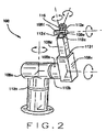
機械24の多軸運動学的リンク機構の一部分を、図2に全般的に参照番号100で示す。リンク機構100は、6個のジョイント112a−112fにより相互に接続される6個の可動リンク108a−108fを含む。ジョイント112a−112eは回転し(revolute)(すなわち回動する)、ジョイント112fは直進する(prismatic)(すなわち摺動する)。リンク機構100はコンピュータ28により操作可能であり、先端部116を規定の通路に沿って作業工程中に位置決めし、制御する。先端部116は、先端部116の上に据付けられたたとえば切削工具または他の種類の工具(図示せず)を有してもよい。リンク機構100は、単なる例示であることが理解されるべきである。機械24は、リンク機構100よりも多少複雑なリンク機構を有してもよく、より多い、より少ないおよび/または異なる種類のリンクおよび/またはジョイントを含んでもよく、および/
またはより多い、より少ないおよび/または異なる自由度および/または自由度の種類を提供してもよい。
A portion of the multi-axis kinematic linkage of
Or more, fewer and / or different degrees of freedom and / or types of degrees of freedom may be provided.
操作中、リンク機構100は、コンピュータ28によって、たとえば1以上の電動機である駆動装置(図示せず)を介して駆動される。リンク108が駆動されるにつれて、他のリンク108の位置決めも影響を受けるであろう。先端部116の位置および姿勢は、X=f(Q)というように、関数集合f()でリンク位置ベクトルQに関係付けられるベクトルXで表わすことができる。J(Q)=(∂xi/∂qj)で定義される関数集合f()のヤコビ行列は、ジョイント112の差分動作を、先端部116の位置および姿勢に対する差分動作それぞれの影響に写像する。前述の関係を線形化により近似すると、JΔQ=ΔXとなり、これにより先端部116のデカルト位置Xの変化は、リンク位置Qの変化に関連付けられる。リンク機構100が特異点に接近するにつれて、ヤコビ行列J(Q)は、次第により悪条件となる。特異点に達すると、ヤコビ行列J(Q)は、階数落ちとなる。
During operation, the
この開示に従うリンク機構100の操作方法の1つの実現例において、特異値分解(SVD)が用いられ、(1)リンク機構100は特異点に接近しているかどうか、およびこのリンク機構は特異点にどれ程近いのか、(2)このリンク機構のどのジョイント112が特異点に接近しているのか、および(3)どの自由度がこの特異点において失われるであろうか、が求められる。概して、特異値分解(SVD)を用いて、U*S*VT=Aというように任意の行列Aを3つの行列U、S、およびVの集合に分解することができ、式中UおよびVは正規直交であり、Sは対角であり成分が降順に対角に配置される。行列Aが与えられたとき、既知のアルゴリズムを用いて、本質的に効率的で安定した方法で、U、S、およびVを計算してもよい。Sの対角成分は、Aの特異値と呼んでもよい。Uの列は、左特異ベクトルと呼んでもよい。Vの列(すなわちVTの行)は、右特異ベクトルと呼んでもよい。
In one implementation of the method of operating the
この開示の1つの実現例に従うヤコビ行列Jの特異値分解の図を、図3に全般的に参照番号200で示す。図2および図3を参照して、ヤコビ行列Jによって、ジョイント112の差分動作は、先端部116の位置決めに対する差分動作それぞれの影響に関連付けられる。Jの各列204は、対応するジョイント112に関連付けられる。行列Jの行列U、S、およびVへの特異値分解の結果、リンク機構100の直交自由度を、最も影響を受けやすい216から最も影響を受けにくい224の順に表わす行列U中の左特異ベクトル208がもたらされる。行列V(行列VTの転換行列)において、Uによって表わされる方向にリンク機構100を移動させるジョイント動作の組合せを表わす右特異ベクトル228が得られる。行列Sにおいて、リンク機構100の「可操作度」の程度を表わすJの特異値236が得られる。したがって、Vの最後の列242(すなわち行列VTの最後の行)において優位であると表わされるジョイント112は、リンク機構100の最も特異なジョイント112であり、Uの最後の列224に表わされる方向は、リンク機構100において潜在的に失われる自由度である。さらに、ヤコビ行列Jの条件数は、最も大きな特異値236を、最も小さな特異値236により除算することにより計算されてもよい。この条件数は、完全条件の行列に対する1から、特異行列に対する無限大までである場合がある。いくつかの実現例においては、数値の安定のために、条件数の逆数が用いられ、これは完全な条件の行列に対する1から、特異行列に対する0までとなる。
A diagram of the singular value decomposition of the Jacobian matrix J according to one implementation of this disclosure is indicated generally by the
この開示の1つの実現例に従う機械24の操作方法のフロー図を、図4Aおよび図4Bに全般的に参照番号300で示す。操作308において、先端部116を所定の経路に沿って移動させるための運動学的ジョイント位置が計算される。操作312において、計算されたジョイント112の位置に対応するヤコビ行列Jが計算され、次にSVDを用いて分解される。操作316において、条件数の逆数が求められる。操作320において、条件数の逆数は、たとえば0.001という予め定義されたしきい値と比較される。条件数の逆数がしきい値よりも大きい場合は、リンク機構100は、如何なる特異点にも接近していないと見なされ、制御は操作340へ進む。
A flow diagram of a method of operating the
条件数の逆数が閾値よりも小さいまたは等しい場合は、リンク機構100の1つ以上のジョイント112が、特異点に接近していると見なされる。したがって、操作324において、特異点の度数nは、次の方法で求められる。条件数の逆数をしきい値より大きくする最も小さな特異値236が求められる。たとえば、特異値236が{0.7、0.4、0.2、0.1、0.0006、0.0001}の場合、条件数の逆数をしきい値0.001より大きくする最も小さな特異値は、0.1(0.1/0.7=0.143、しかし0.0006/0.7=0.00086)であり、特異点の度数nは2である(つまり、2つの特異方向が示される)。
If the reciprocal of the condition number is less than or equal to the threshold, one or more joints 112 of the
操作328において、どのジョイント112が特異および/またはほぼ特異であるかが、最後のn個の右特異ベクトル228の最大成分の位置を特定することにより求められる。操作332において、n個の「仮想ジョイント」が、最後のn個の左特異ベクトル208を取り、これらを最大特異値236で乗算することにより得られる。操作336において、操作328において求められたジョイント112と関連付けられるJの列204は、操作332において得られた「仮想ジョイント」と置き換えられる。
In
操作340から360において、リンク機構100の補正が、米国特許公開番号第20060271241号に記載されるように、たとえばシステムJ*dq=dxの収斂するまでの反復解法により計算される。具体的にはたとえば、操作340において、名目逆運動学計算を用いて、最初のリンク位置ベクトルQiが得られる。操作344において完成状態順運動学計算およびリンク位置ベクトルQiを用いて、実際の先端位置ベクトルXが得られる。操作348において、ΔXベクトルが計算され、これは所望の先端位置ベクトルと実際の先端位置ベクトルの差を示す。操作352において、操作312において得られたヤコビ行列を用いて(ヤコビ行列は操作336において修正されているかもしれないが)、ΔQベクトルが計算される。操作356において、操作352において計算されたΔQベクトルおよびリンク位置ベクトルQiを用いて、新しいリンク位置ベクトルQi+1が得られる。操作360において、収斂は、ベクトルQi+1とQiの絶対差を、所定の収斂基準εと比較することにより調べられる。まだ収斂に達していない場合は、ベクトルQi+1を用いてベクトルQiが更新され、制御は、操作344へ戻る。操作360において収斂に達すると、操作364において条件数の逆数はしきい値よりも小さいかどうか、つまりリンク機構は特異点に接近しているかどうかが判定される。もしそうであれば、操作368において、「仮想ジョイント」を表わしている値はベクトルQi+1から除かれ、これは次に操作372において非特異ジョイント112を補正するために用いられる。SVDは各点に対して一度のみ行なわれ反復解法工程の一部ではないので、前述の方法およびシステムは、線形二次レギュレータ(LQR)または減衰最小二乗法よりも計算コストが低い。
In
前述の方法およびシステムは、数多くの利点を有する。たとえば、左特異ベクトルは、機械の位置または複雑さにかかわらずリンク機構を正確に特異方向に動かすという点で理想の「仮想ジョイント」を提供する。別の利点は、この「仮想ジョイント」を最大特異値に調整することにより、得られる新しいヤコビ行列の条件が最適化され、これにより安定して高速で収束する解が、たとえば前述の方法300の操作340から360において確実なものとされる。さらに、前述の方法の実現例は、特異点の位置の先見的知識を機械に対して要求しないので、同じアルゴリズムを、さまざまな機械に対して変更なしに用いることができる。
The method and system described above have a number of advantages. For example, the left singular vector provides an ideal “virtual joint” in that it moves the linkage exactly in the singular direction regardless of the position or complexity of the machine. Another advantage is that by adjusting this “virtual joint” to the maximum singular value, the condition of the resulting new Jacobian matrix is optimized, so that a solution that converges stably and fast can be obtained, for example, by the
この開示の実現例は、自身の特異点近くで作業する自動化装置の位置決めの精度を向上
させる手段を提供する。精度を向上させることができると、新しい資本設備の取得費用および既存設備の維持費用を少なくすることができる。さらに、この開示のさまざまな実現例は、いくつかの異なる機械形状に対して有効な単一の方法を提供することができ、これにより新たな機械形状に対処するためのソフトウェア開発およびメンテナンスの必要性が低減される。
The implementation of this disclosure provides a means to improve the positioning accuracy of automated devices that work near their singularities. If the accuracy can be improved, the acquisition cost of new capital equipment and the maintenance cost of existing equipment can be reduced. In addition, the various implementations of this disclosure can provide a single method that is effective for several different machine geometries, thereby requiring software development and maintenance to address new machine geometries. Is reduced.
より精密な工作物を生産することができる調整された工作機械を提供することができる。したがって、より高度に精密な部品を、より少ない廃棄物を伴って作ることができる。航空機の製造に関連して実現化すると、より高度に精密な部品の製造により、航空機の重量の減少および性能の向上をもたらすことができる。この開示の実現例により、設定時間の減少と工作機械のより生産的な使用がもたらされ、これにより機械加工費が減少される。 An adjusted machine tool capable of producing a more precise workpiece can be provided. Thus, more highly precise parts can be made with less waste. When realized in the context of aircraft manufacture, the manufacture of more highly precise parts can result in a reduction in aircraft weight and an increase in performance. Implementations of this disclosure result in reduced setup time and more productive use of the machine tool, thereby reducing machining costs.
前述の方法およびシステムのさまざまな実現例により、ソフトウェアを用いて複雑な特異点構成を有する機械(たとえば回転ジョイントを有する6軸多関節ロボット)を補正することが可能となる。補正は、所与の機械に対するすべての特異点の位置または性質の厳密な先見的知識はなくても、多様な機械構成に対して「進行中に」(“on the fly”)提供することができる。同一の中核的な補正ソフトウェアを、機械形状に基づいてこのソフトウェアを書き換える必要なしに、広範な機械構成に対して使用することができる。 Various implementations of the methods and systems described above allow software to be used to correct a machine with a complex singularity configuration (eg, a 6-axis articulated robot having a rotary joint). Corrections can be provided “on the fly” for a variety of machine configurations without the need for strict a priori knowledge of the location or nature of all singularities for a given machine. it can. The same core correction software can be used for a wide range of machine configurations without having to rewrite the software based on the machine geometry.
Claims (4)
前記リンク機構の1つ以上のジョイントによる特異点への接近を検出するために前記リンク機構を監視するステップであって、
(a)ヤコビ行列J(200)の特異値分解J=U*S*V T を求めるステップ(UおよびVは正規直交行列であり、Uの列は左特異ベクトル(208)を、Vの列は右特異ベクトル(228)を構成し、Sは対角行列であり特異値(236)が降順に対角に配置される)(312)と、
(b)特異値分解から求められる特異値のうち最大特異値を求め、各特異値を該最大特異値で除した値を条件数の逆数として求め(316)、所定のしきい値以下(320)となる条件数の逆数の数を接近される特異点の度数nとして求める(324)ステップと、
(c)最後のn個の右特異ベクトル(228)の最大成分の位置を特定することにより特異であるまたは特異に近いn個のジョイント(112)を決定し(328)、最後のn個の左特異ベクトル(208)を最大特異値(236)で乗算し、n個の仮想ジョイントを得(332)、前記n個のジョイント(112)と関連付けられるヤコビ行列Jの列(204)を該仮想ジョイントと置き換えることにより、修正されたヤコビ行列を求めるステップ(336)と、
(d)最初のリンク位置ベクトルQ(i)を求めるステップ(340)と、
(e)前記修正されたヤコビ行列を用いてリンクの位置ベクトルの変化ΔQを計算し(352)、ΔQとQ(i)から、新しいリンク位置ベクトルQ(i+1)を求める(356)ステップと、
(f)Q(i+1)によりQ(i)を更新し、更新後のQ(i)を用いて前記(e)を収斂に達するまで繰り返すステップとを備える、方法。 A multi-axis machine (24) including a kinematic link mechanism (100) having a plurality of links (108) and a plurality of joints (112) connecting the links is numerically controlled using a Jacobian matrix J (200). NC)
A step of monitoring the link mechanism to detect the approach of the singular point by one or more joints prior Symbol link mechanism,
(A) Step for obtaining a singular value decomposition J = U * S * V T of the Jacobian matrix J (200) (U and V are orthonormal matrices, the columns of U are the left singular vectors (208), and the columns of V Constitutes the right singular vector (228), S is a diagonal matrix and the singular values (236) are arranged diagonally in descending order) (312),
(B) The maximum singular value among the singular values obtained from the singular value decomposition is obtained, and a value obtained by dividing each singular value by the maximum singular value is obtained as an inverse number of the condition number (316). (324) calculating the reciprocal number of the condition number as) as the frequency n of the approaching singular point;
(C) determine (328) n joints (112) that are singular or close to singular by locating the largest component of the last n right singular vectors (228), The left singular vector (208) is multiplied by the maximum singular value (236) to obtain n virtual joints (332), and the column (204) of the Jacobian matrix J associated with the n joints (112) is represented by the virtual singular vector (208). the Rukoto replaced with joint, and step (336) for obtaining the modified Jacobian matrix,
(D) obtaining a first link position vector Q (i) (340);
(E) calculating a link position vector change ΔQ using the modified Jacobian matrix (352), and obtaining a new link position vector Q (i + 1) from ΔQ and Q (i) (356);
(F) updating Q (i) by Q (i + 1), and repeating (e) until convergence is reached using the updated Q (i) .
(h)前記Q(i+1)を用いて、非特異ジョイント(112)を補正するステップ(372)とをさらに含む、請求項1に記載された方法。The method of claim 1, further comprising: (h) correcting (372) a non-singular joint (112) using the Q (i + 1).
複数のリンク(108)と前記リンクを接続する複数のジョイント(112)とを有する運動学的リンク機構(100)を含む多軸機械(24)と、
プロセッサ(32)とを備え、前記プロセッサは、
前記リンク機構の1つ以上のジョイントによる特異点への接近を検出するために前記リンク機構を監視し、前記監視は、ヤコビ行列(200)を用いて行なわれ、
(a)ヤコビ行列J(200)の特異値分解J=U*S*V T を求め(UおよびVは正規直交行列であり、Uの列は左特異ベクトル(208)を、Vの列は右特異ベクトル(228)を構成し、Sは対角行列であり特異値(236)が降順に対角に配置される)(312)、
(b)特異値分解から求められる特異値のうち最大特異値を求め、各特異値を該最大特異値で除した値を条件数の逆数として求め(316)、所定のしきい値以下(320)となる条件数の逆数の数を接近される特異点の度数nとして求め(324)、
(c)最後のn個の右特異ベクトル(228)の最大成分の位置を特定することにより特異であるまたは特異に近いn個のジョイント(112)を決定し(328)、最後のn個の左特異ベクトル(208)を最大特異値(236)で乗算し、n個の仮想ジョイントを得(332)、前記n個のジョイント(112)と関連付けられるヤコビ行列Jの列(204)を該仮想ジョイントと置き換えることにより、修正されたヤコビ行列を求め(336)、
(d)最初のリンク位置ベクトルQ(i)を求め(340)、
(e)前記修正されたヤコビ行列を用いてリンクの位置ベクトルの変化ΔQを決定し(352)、ΔQとQ(i)から、新しいリンク位置ベクトルQ(i+1)を求め(356)、
(f)Q(i+1)によりQ(i)を更新し、更新後のQ(i)を用いて前記(e)を収斂に達するまで繰り返すように構成される、システム。 A processing system that is numerically controlled (NC), the NC processing system,
A multi-axis machine (24) including a kinematic linkage (100) having a plurality of links (108) and a plurality of joints (112) connecting the links;
Processor (32), said processor comprising:
Monitoring the linkage to detect an approach to a singularity by one or more joints of the linkage, wherein the monitoring is performed using a Jacobian matrix (200);
(A) Obtain singular value decomposition J = U * S * V T of Jacobian matrix J (200) (U and V are orthonormal matrices, U columns are the left singular vectors (208), and V columns are Right singular vector (228), S is a diagonal matrix and singular values (236) are arranged diagonally in descending order) (312),
(B) The maximum singular value among the singular values obtained from the singular value decomposition is obtained, and a value obtained by dividing each singular value by the maximum singular value is obtained as an inverse number of the condition number (316). ) Is determined as the frequency n of the singular point to be approached (324).
(C) determine (328) n joints (112) that are singular or close to singular by locating the largest component of the last n right singular vectors (228), The left singular vector (208) is multiplied by the maximum singular value (236) to obtain n virtual joints (332), and the column (204) of the Jacobian matrix J associated with the n joints (112) is represented by the virtual singular vector (208). the Rukoto replaced by joint obtains the modified Jacobian matrix (336),
(D) determining the first link position vector Q (i) (340);
(E) using the modified Jacobian matrix to determine the change ΔQ of the position vector of the link (352), from ΔQ and Q (i), for a new link position vector Q (i + 1) (356),
(F) A system configured to update Q (i) by Q (i + 1) and repeat (e) until convergence is reached using the updated Q (i).
(g) (f)の後に、前記リンク機構が特異点に接近しているかどうかを判定し(364)、接近していると判定された場合、前記n個の仮想ジョイントを表わす1つ以上の値を、前記リンク位置ベクトルQ(i+1)から取り除き(368)、(G) After (f), it is determined whether the link mechanism is approaching a singular point (364), and if it is determined that the link mechanism is approaching, one or more representing the n virtual joints The value is removed from the link position vector Q (i + 1) (368),
(h)前記Q(i+1)を用いて、非特異ジョイント(112)を補正することを含むように構成される、請求項3に記載されたシステム。4. The system of claim 3, configured to include (h) correcting non-singular joints (112) using the Q (i + 1).
Applications Claiming Priority (3)
| Application Number | Priority Date | Filing Date | Title |
|---|---|---|---|
| US11/514,072 US8010235B2 (en) | 2005-05-31 | 2006-08-31 | Approaching and compensating for machine kinematic singularities |
| US11/514,072 | 2006-08-31 | ||
| PCT/US2007/018820 WO2008027334A2 (en) | 2006-08-31 | 2007-08-27 | Approaching and compensating for machine kinematic singularities |
Publications (3)
| Publication Number | Publication Date |
|---|---|
| JP2010502454A JP2010502454A (en) | 2010-01-28 |
| JP2010502454A5 JP2010502454A5 (en) | 2013-09-12 |
| JP5393461B2 true JP5393461B2 (en) | 2014-01-22 |
Family
ID=39136516
Family Applications (1)
| Application Number | Title | Priority Date | Filing Date |
|---|---|---|---|
| JP2009526668A Expired - Fee Related JP5393461B2 (en) | 2006-08-31 | 2007-08-27 | Numerical control method for multi-axis machine and processing system using the method |
Country Status (5)
| Country | Link |
|---|---|
| US (1) | US8010235B2 (en) |
| EP (1) | EP2073959B1 (en) |
| JP (1) | JP5393461B2 (en) |
| CN (1) | CN101505925B (en) |
| WO (1) | WO2008027334A2 (en) |
Families Citing this family (11)
| Publication number | Priority date | Publication date | Assignee | Title |
|---|---|---|---|---|
| JP4692488B2 (en) * | 2005-12-26 | 2011-06-01 | 三菱電機株式会社 | Numerical control device and numerical control machine tool |
| JP2008073830A (en) * | 2006-09-25 | 2008-04-03 | Fanuc Ltd | Robot control device |
| FR2960074B1 (en) * | 2010-05-14 | 2012-06-15 | Staubli Sa Ets | METHOD FOR CONTROLLING AN AUTOMATED WORKING CELL |
| US8505484B2 (en) | 2010-06-03 | 2013-08-13 | Delaval Holding Ab | Milking robot, and a milking arrangement |
| DE102010032917A1 (en) * | 2010-07-30 | 2012-04-19 | Brötje-Automation GmbH | Method for offline programming of an NC-controlled manipulator |
| US8532825B1 (en) * | 2010-08-25 | 2013-09-10 | The Boeing Company | Software compensation for kinematically singular machines |
| CN104965517B (en) * | 2015-07-07 | 2018-01-26 | 张耀伦 | A kind of planing method of robot cartesian space track |
| CN105415363B (en) * | 2015-12-23 | 2017-11-17 | 珠海格力电器股份有限公司 | Robot singular point processing method |
| US10065311B1 (en) * | 2016-06-08 | 2018-09-04 | X Development Llc | Singularity handling for robot jogging |
| CN110248775A (en) * | 2017-06-12 | 2019-09-17 | 西门子工业软件有限公司 | For instructing robot to reach to the method and system to set the goal in robot building |
| CN113263496B (en) * | 2021-04-01 | 2022-09-23 | 北京无线电测量研究所 | Method for optimizing path of six-degree-of-freedom mechanical arm and computer equipment |
Family Cites Families (18)
| Publication number | Priority date | Publication date | Assignee | Title |
|---|---|---|---|---|
| US4680519A (en) * | 1985-09-23 | 1987-07-14 | General Electric Co. | Recursive methods for world-to-joint transformation for a robot manipulator |
| US4937759A (en) * | 1986-02-18 | 1990-06-26 | Robotics Research Corporation | Industrial robot with controller |
| US5038089A (en) * | 1988-03-23 | 1991-08-06 | The United States Of America As Represented By The Administrator Of The National Aeronautics And Space Administration | Synchronized computational architecture for generalized bilateral control of robot arms |
| US4967126A (en) * | 1990-01-30 | 1990-10-30 | Ford Aerospace Corporation | Method of controlling a seven degree of freedom manipulator arm |
| SE9400579L (en) * | 1994-02-21 | 1995-08-22 | Asea Brown Boveri | Procedure for controlling the movement of an industrial robot in and around singularities |
| US5793795A (en) * | 1996-12-04 | 1998-08-11 | Motorola, Inc. | Method for correcting errors from a jamming signal in a frequency hopped spread spectrum communication system |
| JPH10329066A (en) * | 1997-05-26 | 1998-12-15 | Mitsubishi Heavy Ind Ltd | Method for specific posture detection and specific posture avoidance for redundant manipulator |
| US6208949B1 (en) * | 1998-07-01 | 2001-03-27 | Adaptive Audio, Inc. | Method and apparatus for dynamical system analysis |
| US6493608B1 (en) * | 1999-04-07 | 2002-12-10 | Intuitive Surgical, Inc. | Aspects of a control system of a minimally invasive surgical apparatus |
| US8004229B2 (en) * | 2005-05-19 | 2011-08-23 | Intuitive Surgical Operations, Inc. | Software center and highly configurable robotic systems for surgery and other uses |
| US6847925B2 (en) * | 2000-06-21 | 2005-01-25 | Hrl Laboratories, Llc | Method and apparatus for modeling three-dimensional electromagnetic scattering from arbitrarily shaped three-dimensional objects |
| US6603281B2 (en) * | 2000-10-16 | 2003-08-05 | Xerox Corporation | High mechanical advantage ratcheting apparatus |
| US6845295B2 (en) * | 2002-03-07 | 2005-01-18 | Fanuc Robotics America, Inc. | Method of controlling a robot through a singularity |
| JP3997405B2 (en) * | 2002-07-26 | 2007-10-24 | 株式会社安川電機 | Mobile manipulator control device and mobile manipulator |
| US6952657B2 (en) * | 2003-09-10 | 2005-10-04 | Peak Sensor Systems Llc | Industrial process fault detection using principal component analysis |
| GB0507618D0 (en) * | 2005-04-15 | 2005-05-25 | Lms Internat Nv | Method and system for dynamic analysis of complex systems |
| US7571027B2 (en) | 2005-05-31 | 2009-08-04 | The Boeing Company | Kinematic singular point compensation systems and methods |
| US8725283B2 (en) * | 2006-08-04 | 2014-05-13 | Hurco Companies, Inc. | Generalized kinematics system |
-
2006
- 2006-08-31 US US11/514,072 patent/US8010235B2/en not_active Expired - Fee Related
-
2007
- 2007-08-27 WO PCT/US2007/018820 patent/WO2008027334A2/en active Application Filing
- 2007-08-27 EP EP07837375.0A patent/EP2073959B1/en not_active Not-in-force
- 2007-08-27 CN CN2007800306231A patent/CN101505925B/en not_active Expired - Fee Related
- 2007-08-27 JP JP2009526668A patent/JP5393461B2/en not_active Expired - Fee Related
Also Published As
| Publication number | Publication date |
|---|---|
| WO2008027334A2 (en) | 2008-03-06 |
| EP2073959A2 (en) | 2009-07-01 |
| US8010235B2 (en) | 2011-08-30 |
| CN101505925A (en) | 2009-08-12 |
| US20070112468A1 (en) | 2007-05-17 |
| JP2010502454A (en) | 2010-01-28 |
| CN101505925B (en) | 2012-07-18 |
| EP2073959B1 (en) | 2018-01-10 |
| WO2008027334A3 (en) | 2008-10-02 |
Similar Documents
| Publication | Publication Date | Title |
|---|---|---|
| JP5393461B2 (en) | Numerical control method for multi-axis machine and processing system using the method | |
| EP1885524B1 (en) | Kinematic singular point compensation systems and methods | |
| Zhu et al. | An off-line programming system for robotic drilling in aerospace manufacturing | |
| Liao et al. | Region-based toolpath generation for robotic milling of freeform surfaces with stiffness optimization | |
| US8972056B2 (en) | Method of finding feasible joint trajectories for an n-dof robot with rotation invariant process (n>5) | |
| Peng et al. | Smoothness-oriented path optimization for robotic milling processes | |
| CN110722576B (en) | Industrial robot milling path global fairing method and system | |
| Liu et al. | An engineering-oriented motion accuracy fluctuation suppression method of a hybrid spray-painting robot considering dynamics | |
| Celikag et al. | Cartesian stiffness optimization for serial arm robots | |
| EP2523786B1 (en) | Method of finding feasible joint trajectories for an n-dof robot with rotation invariant process (n>5) | |
| US8532825B1 (en) | Software compensation for kinematically singular machines | |
| Li et al. | Vibration suppression of an industrial robot with AGV in drilling applications by configuration optimization | |
| CN110989490A (en) | Method for acquiring optimal installation position of workpiece based on contour error | |
| Huang et al. | A new method of inverse kinematics solution for industrial 7DOF robot | |
| Zhu et al. | Inverse kinematics solution of a new circumferential drilling machine for aircraft assembly | |
| Ledesma et al. | A non‐recursive Lagrangian solution of the non‐causal inverse dynamics of flexible multibody systems: The planar case | |
| JP2021186929A (en) | Control method for multi-axis robot | |
| Gao et al. | Robotic milling stability optimization based on robot functional redundancy | |
| KR20160040027A (en) | Muti-degree of freedom(dof) system having parallel structure and method for deriving optimum solution thereof, parallel type manipulator using the same | |
| Tong et al. | Automatic Tool Path Planning Strategy Based on Feature Extraction of 3D Models | |
| Breaz et al. | Using serial industrial robots in cnc milling processes | |
| Walther et al. | Trajectory planning for kinematically redundant robots using jacobi matrix–an industrial implementation | |
| Chu et al. | Real time inverse kinematics of a general 5-axis CNC machine | |
| CN115016258A (en) | Industrial robot flat bed knife milling attitude optimization method and system | |
| JP2002189509A (en) | Method for deriving machine difference of robot |
Legal Events
| Date | Code | Title | Description |
|---|---|---|---|
| RD03 | Notification of appointment of power of attorney |
Free format text: JAPANESE INTERMEDIATE CODE: A7423 Effective date: 20091111 |
|
| A521 | Written amendment |
Free format text: JAPANESE INTERMEDIATE CODE: A821 Effective date: 20100303 |
|
| RD04 | Notification of resignation of power of attorney |
Free format text: JAPANESE INTERMEDIATE CODE: A7424 Effective date: 20100303 |
|
| A621 | Written request for application examination |
Free format text: JAPANESE INTERMEDIATE CODE: A621 Effective date: 20100820 |
|
| A131 | Notification of reasons for refusal |
Free format text: JAPANESE INTERMEDIATE CODE: A131 Effective date: 20120306 |
|
| A601 | Written request for extension of time |
Free format text: JAPANESE INTERMEDIATE CODE: A601 Effective date: 20120604 |
|
| A602 | Written permission of extension of time |
Free format text: JAPANESE INTERMEDIATE CODE: A602 Effective date: 20120613 |
|
| A601 | Written request for extension of time |
Free format text: JAPANESE INTERMEDIATE CODE: A601 Effective date: 20120705 |
|
| A602 | Written permission of extension of time |
Free format text: JAPANESE INTERMEDIATE CODE: A602 Effective date: 20120712 |
|
| A521 | Written amendment |
Free format text: JAPANESE INTERMEDIATE CODE: A523 Effective date: 20120904 |
|
| A521 | Written amendment |
Free format text: JAPANESE INTERMEDIATE CODE: A523 Effective date: 20120906 |
|
| A131 | Notification of reasons for refusal |
Free format text: JAPANESE INTERMEDIATE CODE: A131 Effective date: 20130402 |
|
| A601 | Written request for extension of time |
Free format text: JAPANESE INTERMEDIATE CODE: A601 Effective date: 20130702 |
|
| A602 | Written permission of extension of time |
Free format text: JAPANESE INTERMEDIATE CODE: A602 Effective date: 20130709 |
|
| A524 | Written submission of copy of amendment under section 19 (pct) |
Free format text: JAPANESE INTERMEDIATE CODE: A524 Effective date: 20130731 |
|
| TRDD | Decision of grant or rejection written | ||
| A01 | Written decision to grant a patent or to grant a registration (utility model) |
Free format text: JAPANESE INTERMEDIATE CODE: A01 Effective date: 20130917 |
|
| A61 | First payment of annual fees (during grant procedure) |
Free format text: JAPANESE INTERMEDIATE CODE: A61 Effective date: 20131015 |
|
| R150 | Certificate of patent or registration of utility model |
Ref document number: 5393461 Country of ref document: JP Free format text: JAPANESE INTERMEDIATE CODE: R150 Free format text: JAPANESE INTERMEDIATE CODE: R150 |
|
| R250 | Receipt of annual fees |
Free format text: JAPANESE INTERMEDIATE CODE: R250 |
|
| R250 | Receipt of annual fees |
Free format text: JAPANESE INTERMEDIATE CODE: R250 |
|
| R250 | Receipt of annual fees |
Free format text: JAPANESE INTERMEDIATE CODE: R250 |
|
| R250 | Receipt of annual fees |
Free format text: JAPANESE INTERMEDIATE CODE: R250 |
|
| LAPS | Cancellation because of no payment of annual fees |