JP5390604B2 - Collimated light engine - Google Patents
Collimated light engine Download PDFInfo
- Publication number
- JP5390604B2 JP5390604B2 JP2011513531A JP2011513531A JP5390604B2 JP 5390604 B2 JP5390604 B2 JP 5390604B2 JP 2011513531 A JP2011513531 A JP 2011513531A JP 2011513531 A JP2011513531 A JP 2011513531A JP 5390604 B2 JP5390604 B2 JP 5390604B2
- Authority
- JP
- Japan
- Prior art keywords
- light
- reflector
- baffle
- light source
- collimated
- Prior art date
- Legal status (The legal status is an assumption and is not a legal conclusion. Google has not performed a legal analysis and makes no representation as to the accuracy of the status listed.)
- Expired - Fee Related
Links
Images


Classifications
-
- G—PHYSICS
- G02—OPTICS
- G02F—OPTICAL DEVICES OR ARRANGEMENTS FOR THE CONTROL OF LIGHT BY MODIFICATION OF THE OPTICAL PROPERTIES OF THE MEDIA OF THE ELEMENTS INVOLVED THEREIN; NON-LINEAR OPTICS; FREQUENCY-CHANGING OF LIGHT; OPTICAL LOGIC ELEMENTS; OPTICAL ANALOGUE/DIGITAL CONVERTERS
- G02F1/00—Devices or arrangements for the control of the intensity, colour, phase, polarisation or direction of light arriving from an independent light source, e.g. switching, gating or modulating; Non-linear optics
- G02F1/01—Devices or arrangements for the control of the intensity, colour, phase, polarisation or direction of light arriving from an independent light source, e.g. switching, gating or modulating; Non-linear optics for the control of the intensity, phase, polarisation or colour
- G02F1/13—Devices or arrangements for the control of the intensity, colour, phase, polarisation or direction of light arriving from an independent light source, e.g. switching, gating or modulating; Non-linear optics for the control of the intensity, phase, polarisation or colour based on liquid crystals, e.g. single liquid crystal display cells
- G02F1/133—Constructional arrangements; Operation of liquid crystal cells; Circuit arrangements
- G02F1/1333—Constructional arrangements; Manufacturing methods
- G02F1/1335—Structural association of cells with optical devices, e.g. polarisers or reflectors
- G02F1/1336—Illuminating devices
- G02F1/133602—Direct backlight
- G02F1/133605—Direct backlight including specially adapted reflectors
-
- G—PHYSICS
- G02—OPTICS
- G02F—OPTICAL DEVICES OR ARRANGEMENTS FOR THE CONTROL OF LIGHT BY MODIFICATION OF THE OPTICAL PROPERTIES OF THE MEDIA OF THE ELEMENTS INVOLVED THEREIN; NON-LINEAR OPTICS; FREQUENCY-CHANGING OF LIGHT; OPTICAL LOGIC ELEMENTS; OPTICAL ANALOGUE/DIGITAL CONVERTERS
- G02F1/00—Devices or arrangements for the control of the intensity, colour, phase, polarisation or direction of light arriving from an independent light source, e.g. switching, gating or modulating; Non-linear optics
- G02F1/01—Devices or arrangements for the control of the intensity, colour, phase, polarisation or direction of light arriving from an independent light source, e.g. switching, gating or modulating; Non-linear optics for the control of the intensity, phase, polarisation or colour
- G02F1/13—Devices or arrangements for the control of the intensity, colour, phase, polarisation or direction of light arriving from an independent light source, e.g. switching, gating or modulating; Non-linear optics for the control of the intensity, phase, polarisation or colour based on liquid crystals, e.g. single liquid crystal display cells
- G02F1/133—Constructional arrangements; Operation of liquid crystal cells; Circuit arrangements
- G02F1/1333—Constructional arrangements; Manufacturing methods
- G02F1/1335—Structural association of cells with optical devices, e.g. polarisers or reflectors
- G02F1/1336—Illuminating devices
- G02F1/133602—Direct backlight
- G02F1/133603—Direct backlight with LEDs
-
- G—PHYSICS
- G02—OPTICS
- G02F—OPTICAL DEVICES OR ARRANGEMENTS FOR THE CONTROL OF LIGHT BY MODIFICATION OF THE OPTICAL PROPERTIES OF THE MEDIA OF THE ELEMENTS INVOLVED THEREIN; NON-LINEAR OPTICS; FREQUENCY-CHANGING OF LIGHT; OPTICAL LOGIC ELEMENTS; OPTICAL ANALOGUE/DIGITAL CONVERTERS
- G02F1/00—Devices or arrangements for the control of the intensity, colour, phase, polarisation or direction of light arriving from an independent light source, e.g. switching, gating or modulating; Non-linear optics
- G02F1/01—Devices or arrangements for the control of the intensity, colour, phase, polarisation or direction of light arriving from an independent light source, e.g. switching, gating or modulating; Non-linear optics for the control of the intensity, phase, polarisation or colour
- G02F1/13—Devices or arrangements for the control of the intensity, colour, phase, polarisation or direction of light arriving from an independent light source, e.g. switching, gating or modulating; Non-linear optics for the control of the intensity, phase, polarisation or colour based on liquid crystals, e.g. single liquid crystal display cells
- G02F1/133—Constructional arrangements; Operation of liquid crystal cells; Circuit arrangements
- G02F1/1333—Constructional arrangements; Manufacturing methods
- G02F1/1335—Structural association of cells with optical devices, e.g. polarisers or reflectors
- G02F1/1336—Illuminating devices
- G02F1/133602—Direct backlight
- G02F1/133611—Direct backlight including means for improving the brightness uniformity
Description
本開示は、ディスプレイ又はその他の図形を裏側から照らす、バックライトなどへの使用に適する、部分的に光をコリメートする照明装置に関する。 The present disclosure relates to a lighting device that partially collimates light, suitable for use in a backlight or the like that illuminates a display or other graphic from the back side.
バックライトは、バックライトの出力エリアに対して内部光源が位置付けられる場所、及びバックライトの「出力エリア」が表示装置の可視エリア又は領域のどこに対応しているかによって、2つのカテゴリうちの1つに該当すると考えることができる。本明細書で、このバックライトの「出力エリア」は時に、「出力領域」又は「出力表面」とも呼ばれ、その領域又は表面そのものと、その領域又は表面の面積(平方メートル、平方ミリメートル、平方インチなどの単位を有する数量)と、を区別する。 The backlight is one of two categories depending on where the internal light source is positioned relative to the output area of the backlight and where the “output area” of the backlight corresponds to the visible area or area of the display device. It can be considered that it corresponds to. In this specification, the “output area” of this backlight is sometimes referred to as the “output area” or “output surface”, and the area or surface itself and the area or surface area (square meters, square millimeters, square inches). And a quantity having a unit such as).
第1のカテゴリは「エッジライト」方式である。エッジライト方式のバックライトでは、平面図の視点で見て、1つ以上の光源がバックライト構造の外側の境界又は外周に沿って、通常は出力領域に相当する領域又は範囲の外側に配置される。光源はしばしば、バックライトの出力面積の外縁となるフレーム又はベゼルによって隠される。光源は、典型的には、特にラップトップコンピュータディスプレイのように極めて薄いバックライトが望まれる場合には、「ライトガイド」と呼ばれる構成要素内に光を放射する。このライトガイドは透明、中実であり、長さ及び幅の寸法がバックライト出力面積の大きさとほぼ同じ、比較的薄いプレートである。ライトガイドは、ライトガイドの全長又は幅をはさんだ縁部に取り付けられたランプからの光をバックライトの反対側の縁部へと移動させる又はガイドするために全内部反射(TIR)を用い、局所的抽出構造体の非均一パターンがライトガイドの表面に提供されて、ライトガイドから出たこの導かれた光の一部を、バックライトの出力エリアに向け直す。こうしたバックライトは、ライトガイドの後ろ又は下に配置される反射材料などの光制御フィルム、並びに、ライトガイドの前方又は上に配置される反射偏光フィルム及びプリズム状BEFフィルムを通常、更に有することによって、法線方向の輝度が高くなっている。 The first category is the “edge light” method. In an edge-lit backlight, as seen from a plan view, one or more light sources are placed along the outer boundary or circumference of the backlight structure, usually outside the area or range corresponding to the output area. The The light source is often hidden by a frame or bezel that is the outer edge of the output area of the backlight. The light source typically emits light into a component called a “light guide”, particularly when a very thin backlight is desired, such as a laptop computer display. This light guide is transparent and solid, and is a relatively thin plate whose length and width dimensions are approximately the same as the size of the backlight output area. The light guide uses total internal reflection (TIR) to move or guide light from a lamp attached to the light guide's entire length or width across the edge to the opposite edge of the backlight, A non-uniform pattern of local extraction structures is provided on the surface of the light guide to redirect a portion of this guided light emerging from the light guide to the output area of the backlight. Such a backlight typically has a light control film, such as a reflective material, located behind or below the light guide, as well as a reflective polarizing film and a prismatic BEF film, usually located above or above the light guide. The brightness in the normal direction is high.
出願人の見地では、既存のエッジライト式バックライトの欠点又は制限として、特にバックライトのサイズが大きい場合にライトガイドと関連した質量又は重量が比較的大きいこと、特定のバックライトサイズ及び特定の光源構造のためにライトガイドを射出成形や他の方法で製造しなければならないので、バックライト間で互換性のない構成要素を使用しなければならないこと、既存の抽出構造パターンと同様にバックライト内の位置に応じてかなりの空間不均一性を必要とする構成要素を使用しなければならないこと、並びにバックライトのサイズが大きくなるほど、長方形の面積に対する周囲の長さの比率が、特徴的な面内寸法L(例えば、所定の縦横比の長方形では、バックライトの出力領域の長さ、幅、又は対角線寸法)とともに線形(1/L)に低下するので、ディスプレイの縁部に沿った空間又は「不動産」が制限されるため十分な照明を提供するのが困難になることなどが挙げられる。加工及び研磨作業に費用がかさむことから、中実のライトガイドの外周以外の点から光を入射させることは困難である。 From the applicant's point of view, the disadvantages or limitations of existing edge-lit backlights include the relatively large mass or weight associated with the light guide, especially when the backlight size is large, the specific backlight size and the specific Because the light guide must be manufactured by injection molding or other methods for the light source structure, components that are not compatible between the backlights must be used, as well as the existing extraction structure pattern Components that require significant spatial non-uniformity depending on their position within, and the larger the size of the backlight, the more the ratio of the perimeter length to the rectangular area is characteristic Along with in-plane dimension L (for example, the length, width, or diagonal dimension of the output area of the backlight in a rectangle with a predetermined aspect ratio) Since falls in the form (1 / L), and the like can be difficult to provide sufficient illumination for the space along the edge of the display or "real estate" is restricted. Since the processing and polishing operations are expensive, it is difficult to make light incident from a point other than the outer periphery of the solid light guide.
第2のカテゴリは「直下型」方式である。直下型バックライトでは、平面図の視点で見て、1つ以上の光源は、実質的に出力エリアに対応したエリア又はゾーン内に、通常はゾーン内の規則的な配列又はパターンで配置される。あるいは、直下型バックライトの光源は、バックライトの出力領域のすぐ裏側に配置されているとも言える。強く拡散するプレートは、通常、光源の上側に取り付けられて、光を出力領域一面に広げる。この場合も、反射偏光フィルム及びプリズムBEFフィルムなどの光管理フィルムをディフューザープレートの上に設置することによって法線方向の輝度及び効率を改善することができる。直下型バックライトの均一性を保つ上で、ランプ間の間隔を広げるに従いバックライトの厚みを増大させなければならないところが不便な点である。ランプの数はシステムのコストに直接影響するため、この兼ね合いが直下型システムの欠点である。 The second category is the “direct type” method. In direct type backlights, when viewed from a plan view, one or more light sources are arranged in an area or zone substantially corresponding to the output area, usually in a regular arrangement or pattern within the zone. . Alternatively, it can be said that the light source of the direct type backlight is disposed immediately behind the output region of the backlight. A strongly diffusing plate is usually mounted above the light source to spread the light over the output area. In this case as well, the luminance and efficiency in the normal direction can be improved by installing a light management film such as a reflective polarizing film and a prism BEF film on the diffuser plate. In order to maintain the uniformity of the direct type backlight, it is inconvenient that the thickness of the backlight must be increased as the distance between the lamps is increased. This trade-off is a drawback of the direct type system because the number of lamps directly affects the cost of the system.
出願者の所見によると、既存の直下型バックライトの欠点又は制限には、強く拡散するプレートに付随する非効率性、LED光源の場合、適切な均一性及び輝度を得るために多数のLED光源が必要であり、それに伴い構成要素のコストが高くなり発熱が増大する、達成可能なバックライトの薄さが制限され、この厚さを超えると光源は不均一で望ましくない「パンチスルー」を生成し、各光源の上側の出力エリア内に輝点が出現する点などが挙げられる。赤、緑、及び青色LEDなどのマルチカラーLEDクラスタを使用する場合は、色や輝度が不均一となることもある。 Applicants' observations indicate that the disadvantages or limitations of existing direct backlights include inefficiencies associated with strongly diffusing plates, in the case of LED light sources, a large number of LED light sources in order to obtain adequate uniformity and brightness. Is required, which increases the cost of components and increases heat generation, limiting the achievable backlight thinness, beyond which the light source produces non-uniform and undesirable "punch-through" In addition, a bright spot appears in the output area above each light source. When using multi-color LED clusters such as red, green, and blue LEDs, the color and brightness may be non-uniform.
場合によっては、直下型バックライトではバックライトの周囲に1つ又は複数の光源を含むことができるか、又はエッジライト型バックライトでは出力領域の裏側に直接1つ又は複数の光源を含むことができる。そのような場合、光の大半がバックライトの出力領域の裏側から直接発せられる場合は、このバックライトは「直下型」と見なされ、光の大半がバックライトの出力領域の周囲から発せられる場合は、このバックライトは「エッジライト型」と見なされる。 In some cases, a direct type backlight may include one or more light sources around the backlight, or an edge light type backlight may include one or more light sources directly behind the output area. it can. In such cases, if most of the light is emitted directly from the back side of the backlight output area, the backlight is considered “directly underneath” and most of the light is emitted from around the backlight output area. This backlight is regarded as an “edge light type”.
バックライトとして容易に、また費用効果の高い方法で組み立てられることができる光源を有することが望ましい。また、エッジライト型構成又は直下型構成のいずれかで使用できる光源を有することが望ましい。また、標準化部品を使用することで、更なる部品を追加することにより大きいサイズを達成することができ、さまざまな大きさのバックライトを組み立てる方法を有することが望ましい。 It would be desirable to have a light source that can be easily assembled in a cost effective manner as a backlight. It is also desirable to have a light source that can be used in either an edge light configuration or a direct configuration. It is also desirable to have a method of assembling backlights of various sizes, using standardized parts, which can achieve a larger size by adding additional parts.
一態様では、第1面を有する反射体と、第1面に隣接して取り付けられた光源及び回路と、を含むコリメート光エンジンを開示する。コリメート光エンジンは、光源が、反射体に対する法線から50度未満の角度からは見えないように、光源の上に配置され反射体の一部の上に張り出しているバッフルを更に含む。一態様では、反射体を提供する工程と、平面回路化基板に実装された光源を提供する工程と、反射体を形成してバッフル及び背面反射体を提供する工程と、バッフルと背面反射体との間に平面回路化基板を取り付ける工程と、を含む、コリメート光エンジンを作製する方法を開示する。光源は、平面回路化基板にほぼ平行な放射光軸を有し、バッフルは、背面反射体の一部の上に張り出しており、背面反射体に対する法線から50度未満の角度からは光源を見えなくする。 In one aspect, a collimated light engine is disclosed that includes a reflector having a first surface and a light source and circuit mounted adjacent to the first surface. The collimated light engine further includes a baffle disposed over the light source and overhanging a portion of the reflector such that the light source is not visible from an angle less than 50 degrees from the normal to the reflector. In one aspect, providing a reflector, providing a light source mounted on a planar circuit board, forming a reflector to provide a baffle and a back reflector, a baffle and a back reflector, Attaching a planar circuitized substrate between the two, a method of making a collimated light engine is disclosed. The light source has a radiation optical axis that is substantially parallel to the planar circuit board, the baffle overhangs a portion of the back reflector, and the light source is viewed from an angle less than 50 degrees from the normal to the back reflector. Make it invisible.
一態様では、反射体を提供する工程と、平面回路化基板に実装された光源を提供する工程と、平面回路化基板を反射体に取り付ける工程と、バッフルを提供する工程と、バッフルを光源の上に取り付ける工程と、を含む、コリメート光エンジンを作製する方法を開示する。光源は、平面回路化基板にほぼ平行な放射光軸を有し、バッフルは、背面反射体の一部の上に張り出しており、背面反射体に対する法線から50度未満の角度からは光源を見えなくする。 In one aspect, providing a reflector, providing a light source mounted on a planar circuitized substrate, attaching the planar circuitized substrate to the reflector, providing a baffle, and attaching the baffle to the light source A method of making a collimated light engine comprising the steps of: The light source has a radiation optical axis that is substantially parallel to the planar circuit board, the baffle overhangs a portion of the back reflector, and the light source is viewed from an angle less than 50 degrees from the normal to the back reflector. Make it invisible.
一態様では、反射体を提供する工程と、反射体上で回路の形成する工程と、光源を回路に取り付ける工程と、反射体を形成してバッフル及び背面反射体を提供する工程と、を含む、コリメート光エンジンを作製する方法を開示する。光源は、反射体にほぼ平行な放射光軸を有し、バッフルは、回路及び光源を含む背面反射体の一部の上に張り出しており、背面反射体に対する法線から50度未満の角度からは光源を見えなくする。 In one aspect, the method includes providing a reflector, forming a circuit on the reflector, attaching a light source to the circuit, and forming the reflector to provide a baffle and a back reflector. A method of making a collimated light engine is disclosed. The light source has a radiating optical axis substantially parallel to the reflector, and the baffle overhangs a portion of the back reflector that includes the circuit and the light source and from an angle less than 50 degrees from the normal to the back reflector. Makes the light source invisible.
本願のこれらの態様及び他の態様は、以下の詳細な説明から明らかとなろう。しかし、上記要約は、請求された主題に関する限定として決して解釈されるべきでなく、主題は、手続処理の間補正することができる添付の特許請求の範囲によってのみ規定される。 These and other aspects of the present application will be apparent from the detailed description below. However, the above summary should in no way be construed as a limitation on the claimed subject matter, which is defined only by the appended claims that may be amended during procedural processing.
本明細書を通して、添付の図面を参照し、ここで、同様の参照番号は同様の要素を示す。
図面は、必ずしも一定の比率の縮尺ではない。図中で用いられる類似の数字は、類似の構成要素を示す。しかし、所与の図中の構成要素を意味する数字の使用は、同一数字でラベル付けされた別の図中の構成要素を制約するものではないことは理解されよう。 The drawings are not necessarily to scale. Similar numerals used in the figures indicate similar components. However, it will be understood that the use of numbers to refer to components in a given figure does not constrain components in another figure that are labeled with the same number.
本開示は、ディスプレイのバックライトなど薄い照明素子に使用可能な効率性の高いコリメート光エンジンに関するものである。最も一般的な形態において、エンジンの光源はLEDの配列でフレキシブル回路に取り付けられ、楔形に成形された2つの高反射性要素の間に挟まれて、LED配列から放射された光が各要素の間で部分的にコリメートされる。一実施形態では、高反射性要素の少なくとも1つは高反射性フィルムである。光が部分的にコリメートされることで、光は、反射面により画定される狭い範囲の角度以内で進む。コリメートされた光は、バックライトなどの薄い中空の空洞での使用に好適であり得る。 The present disclosure relates to a highly efficient collimated light engine that can be used in thin lighting elements such as display backlights. In the most common form, the engine light source is attached to the flexible circuit in an array of LEDs, sandwiched between two highly reflective elements shaped like wedges, and the light emitted from the LED array is transmitted to each element. Partially collimated between. In one embodiment, at least one of the highly reflective elements is a highly reflective film. As the light is partially collimated, the light travels within a narrow range of angles defined by the reflective surface. The collimated light may be suitable for use in a thin hollow cavity such as a backlight.
一態様では、光エンジンはフレックス回路に実装した厚さ0.6mmの一連の側面発光白色LED配列(通常、複数のLEDチップを一列に並べたもの)を積層した3M社から入手可能な強化鏡面反射体(Enhanced Specular Reflector)(Vikuiti(商標)ESR)フィルムを2ストリップ含み、LEDがESRストリップの間に入るように配置される。LEDは、LED配列の厚みによりLED配列の発光面に隣接したESRフィルムが持ち上げられて、光をコリメートする楔形を形成するように、ESRフィルムの間に配置される。組み立てられた光エンジンは、照明及び均一性の必要条件により、反射性バックプレーン上で様々な配置構成で配置されることができる。LEDに重なって楔形の上面を形成するESRのストリップは、上から見た場合にLEDを覆い隠す役割も果たすのでバッフルと呼ぶことができる。他の箇所で言及したように、直下型バックライトでは、LEDの表面に近接した部分での強烈な光がこの光の上に配置された拡散シートを通って漏れてしまう「パンチスルー」が頻繁に生じる。バッフルを提供することにより、LEDの発光面は、垂直位置から50度、60度、70度、75度を超える角度で、又は更には80度を超える非常に大きな角度からでなければ見ることができない(すなわち視界から隠れる)。 In one aspect, the light engine is a reinforced mirror surface available from 3M, which is a stack of a series of 0.6mm thick side-emitting white LED arrays (typically a plurality of LED chips arranged in a row) mounted on a flex circuit. It includes two strips of Enhanced Specular Reflector (Vikuiti ™ ESR) film, with the LEDs positioned between the ESR strips. The LEDs are placed between the ESR films so that the thickness of the LED array lifts the ESR film adjacent to the light emitting surface of the LED array to form a wedge shape that collimates the light. The assembled light engine can be arranged in various arrangements on the reflective backplane, depending on lighting and uniformity requirements. The ESR strip that overlaps the LED and forms a wedge-shaped top surface can also be called a baffle because it also serves to cover the LED when viewed from above. As mentioned elsewhere, direct-type backlights often have “punch-through” in which intense light near the surface of the LED leaks through the diffusion sheet placed above this light. To occur. By providing a baffle, the light emitting surface of the LED can only be viewed at angles greater than 50, 60, 70, 75 degrees from the vertical position, or even from a very large angle greater than 80 degrees. Cannot (ie hide from view).
一態様では、光エンジンは反射性剛性回路基板に実装した複数のLEDを使用することが可能であり、ESRフィルムなどの2つの反射性フィルムの間に配置することができる。一実施形態では、光が回路基板に対してほぼ垂直に放射されるようにLEDを回路基板に取り付け、バッフルが基板の縁部で支えられるように基板を配置し、楔内で光が部分的にコリメートされるようにLEDからの光を放射させることができる。一実施形態では、LEDは、反射性を有するバックプレーンに垂直の軸の周囲を360未満の角度広がり内で光を放射する。 In one aspect, the light engine can use multiple LEDs mounted on a reflective rigid circuit board and can be placed between two reflective films, such as an ESR film. In one embodiment, the LEDs are mounted on the circuit board so that light is emitted substantially perpendicular to the circuit board, the board is positioned such that the baffle is supported by the edge of the board, and the light is partially within the wedge. The light from the LED can be emitted so as to be collimated. In one embodiment, the LED emits light within an angular spread of less than 360 around an axis perpendicular to the reflective backplane.
一態様では、バッフルはLEDの上に配置され、LEDの発光面を超えて張り出している。一実施形態では、バッフルは背面反射体と交差する別のフィルムでもよい。別の実施形態では、背面反射体を楔形に折り畳むなどして、バッフルを含むように背面反射体を形成することにより、バッフルを背面反射体と一体化させることができる。バッフルに使用する材料は、反射性金属を含む反射体、若しくは干渉反射体、部分的な反射体、半鏡面反射体、非対称反射体、又はこれらの組み合わせを含むことができる。一部の実施形態では、バッフルの材質及び光学特性が全体にわたって同一であるように、バッフルは均一のものでもよい。他の実施形態では、バッフルが、穿孔、スリット、鋸歯、溝などを有して不均一であることにより、バッフルを物理的に変化させてもよく、又はバッフルの材料が、両方とも波長に依存し得る鏡面反射率及び拡散反射率の両方における変更などの不均一な光学特性を有してもよい。更に他の実施形態では、バッフルの少なくとも一部分が、光を低変換する蛍光体など、光源から放射された光のスペクトル特性を変更できる材料を含むことができる。 In one aspect, the baffle is disposed over the LED and extends beyond the light emitting surface of the LED. In one embodiment, the baffle may be another film that intersects the back reflector. In another embodiment, the baffle can be integrated with the back reflector by forming the back reflector to include the baffle, such as by folding the back reflector into a wedge shape. The material used for the baffle can include a reflector comprising a reflective metal, or an interference reflector, a partial reflector, a semi-specular reflector, an asymmetric reflector, or a combination thereof. In some embodiments, the baffle may be uniform so that the material and optical properties of the baffle are the same throughout. In other embodiments, the baffle may be physically altered by being non-uniform with perforations, slits, saw teeth, grooves, etc., or the material of the baffle is both wavelength dependent It may have non-uniform optical properties such as changes in both specular and diffuse reflectance that may be possible. In still other embodiments, at least a portion of the baffle can include a material that can alter the spectral characteristics of the light emitted from the light source, such as a phosphor that converts light low.
一部の実施形態では、バッフルの材料は、ESRフィルムを含むことができる。他の実施形態では、ESRフィルムを厚い表面薄層と組み合わせたり、又は別のフィルムに積層して、バッフルの曲げ剛性を増すことができる。一部の実施形態では、バッフルの厚さは約0.13〜約0.26mm(5〜約10ミル)である。 In some embodiments, the material of the baffle can include an ESR film. In other embodiments, the ESR film can be combined with a thick skin layer or laminated to another film to increase the bending stiffness of the baffle. In some embodiments, the baffle thickness is from about 0.13 to about 0.26 mm (5 to about 10 mils).
バッフルは、適切な形状を選択することで、任意の所望の光コリメーション度を提供できる。一実施形態では、バッフルは、LED配列の上縁と接触することによりLED配列の上に楔形を形成する平面的なフィルムを含む。他の実施形態では、他の箇所で説明するように、バッフルを放物線状、複合放物線状、階段状の楔形、ひし形などに形成し、曲げ、折ることで、非平面的な形状に形成することができる。 The baffle can provide any desired degree of light collimation by selecting an appropriate shape. In one embodiment, the baffle includes a planar film that forms a wedge shape on the LED array by contacting the upper edge of the LED array. In other embodiments, as described elsewhere, the baffle is formed into a non-planar shape by forming it into a parabolic shape, a compound parabolic shape, a stepped wedge shape, a diamond shape, etc., and bending and folding. Can do.
一態様では、光エンジンを連続して製造することができる。一実施形態では、工程は、ESRフィルムなどのフレキシブル底面反射体を提供することと、フレキシブル回路に実装されたLED配列モジュールを提供することと、フレキシブル回路をフレキシブル底面反射体に取り付けることと、LEDから放射される光が底面反射体にほぼ平行な方向に伝搬するよう、第2のESRフィルムをLED配列モジュールの上に取り付けることと、を含む。別の実施形態では、工程は、ESRフィルムなどのフレキシブル底面反射体を提供することと、底面反射体を折り畳むことによりバッフルを形成することと、フレキシブル回路に実装されたLED配列モジュールを提供することと、バッフルと底面反射体との間にLED配列モジュールを取り付けることと、を含む。 In one aspect, the light engine can be manufactured continuously. In one embodiment, the process includes providing a flexible bottom reflector, such as an ESR film, providing an LED array module mounted on the flexible circuit, attaching the flexible circuit to the flexible bottom reflector, Mounting a second ESR film on the LED array module such that light emitted from the light propagates in a direction substantially parallel to the bottom reflector. In another embodiment, the process provides a flexible bottom reflector, such as an ESR film, forms a baffle by folding the bottom reflector, and provides an LED array module mounted on the flexible circuit. And mounting an LED array module between the baffle and the bottom reflector.
一態様では、コリメート光エンジンはLCD用の薄いバックライトなどの照明組立品に使用できる。一実施形態では、コリメート光エンジンは、バックライトへの光の「累進的入射装置(progressive injector)」と考えることができる。光はバックライトの全長を進むにつれて強度が低下するため、コリメート光エンジンを追加してバックライトの出力を増加させることで、より大きなバックライトを簡単に作ることができる。一実施形態では、コリメート光エンジンはバックライト内で、少なくとも3つの機能を実行するのに使用することができる。第1機能は、光がバックライトの全長を伝搬できるように、背面反射体にほぼ平行な比較的狭い範囲の角度以内で光をバックライトに入射させることである。第2機能は、ディスプレイを前から(出力面に対して垂直に)見たときに、LED配列の明るい面を見えなくし、パンチスルーを減少させることである。第3機能は、例えば他の光源からバックライトの全長を伝搬してくる光に対して反射面を提供することで、光の伝搬方向を変えて、光がバックライトの前方から出るようにすることである。 In one aspect, the collimated light engine can be used in lighting assemblies such as thin backlights for LCDs. In one embodiment, the collimated light engine can be thought of as a “progressive injector” of light into the backlight. Since light decreases in intensity as it travels along the entire length of the backlight, a larger backlight can be easily created by adding a collimating light engine to increase the output of the backlight. In one embodiment, the collimated light engine can be used to perform at least three functions in the backlight. The first function is to allow light to enter the backlight within a relatively narrow range of angles that are substantially parallel to the back reflector so that the light can propagate through the entire length of the backlight. The second function is to make the bright side of the LED array invisible and reduce punch through when the display is viewed from the front (perpendicular to the output surface). The third function is to provide a reflective surface for light propagating from the other light source, for example, over the entire length of the backlight, thereby changing the light propagation direction so that the light exits from the front of the backlight. That is.
一態様では、第1機能は、LED配列からの光を部分的にコリメートするバッフルの下面により成し遂げられる。バッフルは、下面(LEDに最も近い側)において、バックライトの空洞部に最も近い側とは異なる特性を有することができる。LEDは通常、発光面から半球状に光を放射し、LEDの光軸は発光面に対して垂直である。LEDは、光が概してLEDの光軸に沿ってバックライト全長を伝搬するように配置される。光軸から外れた角度で伝搬する放射された光の一部は、バッフルで反射され光軸に向って方向転換されて、光を部分的にコリメートする。 In one aspect, the first function is accomplished by the lower surface of the baffle that partially collimates light from the LED array. The baffle can have different properties on the bottom surface (side closest to the LED) than on the side closest to the backlight cavity. The LED usually emits light in a hemispherical shape from the light emitting surface, and the optical axis of the LED is perpendicular to the light emitting surface. The LEDs are arranged so that light propagates along the entire length of the backlight, generally along the optical axis of the LEDs. A portion of the emitted light propagating at an angle off the optical axis is reflected by the baffle and redirected toward the optical axis to partially collimate the light.
一態様では、第2機能も、バッフルがLED配列の上に張り出す長さにより成し遂げられる。バッフルを長くすることで光のコリメート度を改善でき、これは背面反射体とバッフル間の角度に影響を及ぼす。長いバッフルの利点は、正面から見た場合にLEDの表面が見えないことである。多くの場合、正面から見た場合にLEDが極端に大きな角度、例えば背面反射体に対する垂直位置から約50度、60度、70度、75度、又は更には80度を超える角度以外からは見ることができないように十分にバッフルをLEDの上に張り出させることは有益であり得る。 In one aspect, the second function is also accomplished by the length that the baffle overhangs the LED array. Increasing the baffle can improve light collimation, which affects the angle between the back reflector and the baffle. The advantage of a long baffle is that the LED surface is not visible when viewed from the front. In many cases, the LED is viewed from an extremely large angle when viewed from the front, for example, other than an angle greater than about 50, 60, 70, 75, or even 80 degrees from the vertical position relative to the back reflector. It may be beneficial to have the baffle overhang the LED enough that it cannot.
一態様では、第3機能はバッフルの設計により達成できる。例えば、バッフル上部の斜面は、光の方向を変えるために使用する。LEDの上に配置されたバッフルでは、バッフルの裏面が入射装置の後ろからの光を反射することで、バックライトの上部に光の方向を変更することができる。また、バッフルを楔形又はひし形にすることで、光エンジンの出射孔に向って伝搬している光をバックライトの上部に向って方向付けることができる。バッフルの構成について、図を参照しながら更に説明する。 In one aspect, the third function can be achieved by baffle design. For example, the slope at the top of the baffle is used to change the direction of light. In the baffle disposed on the LED, the back surface of the baffle reflects light from behind the incident device, so that the direction of light can be changed to the upper part of the backlight. Further, by making the baffle into a wedge shape or a diamond shape, the light propagating toward the exit hole of the light engine can be directed toward the upper part of the backlight. The configuration of the baffle will be further described with reference to the drawings.
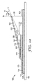
図1aは、本開示の一態様に従い、第1接着層105で後方基板150に取り付けられたコリメート光エンジン100の一実施形態の側面図を描く。図1aのコリメート光エンジン100は、他の箇所で説明するように、光エンジンの連続生産に適合させることができる。コリメート光エンジン100は、反射体100の第1表面に隣接して取り付けられた光源130及び回路145を含む。一実施形態では、反射体110はフィルムなどのフレキシブル反射体である。光源130及び回路145は、フレキシブル基板140に配置することができ、これは続いて第2接着層で反射体110に取り付けられる。
FIG. 1 a depicts a side view of one embodiment of a collimated
光源130は、放射光軸136が放射面135から垂直に延び、反射体110にほぼ平行になるように配置される。別の実施形態では、放射光軸136はバッフル120及び反射体110により形成される楔形を2等分する横断面にほぼ平行である。光源130は、例えばLEDなど、表面から光を放射する任意の光源であり得る。表面135からの光は、表面135から概して半球状に放射される。
The
コリメート光エンジンは、白色光を表面から半球状に放射できるように光を低変換する蛍光体を備えた青色又は紫外線放射LEDなどの表面放射LED、赤/緑/青(RGB)LEDの配列などの個々の有色LED、「Backlight and Display System Using Same」なる名称のPCT特許出願第US2008/064133号(代理人整理番号63274WO004)に記載されたその他のものなど、任意の好適な光源を含むことができる。開示する照明装置の光源として、別個のLED光源の代わりに、又はLED光源に追加して、線形の冷陰極蛍光ランプ(CCFL)又は熱陰極蛍光ランプ(HCFL)などの別の可視光発光体を使用してもよい。更に、例えば冷白色及び温白色を含む(CCFL/LED)、CCFL/HCFL、例えば異なるスペクトルを放射するものなどの複合システムを使用することができる。発光体の組み合わせは、幅広く異なってもよく、LEDとCCFL、及び例えば複数のCCFL、異なる色の複数のCCFL、及びLEDとCCFLなどの多数を含むことが可能である。 Collimated light engines include surface emitting LEDs such as blue or ultraviolet emitting LEDs with phosphors that convert light low so that white light can be emitted hemispherically from the surface, red / green / blue (RGB) LED arrays, etc. May include any suitable light source such as those described in PCT Patent Application No. US2008 / 064133 (Attorney Docket No. 63274WO004) named “Backlight and Display System Using Name” it can. Another visible light emitter, such as a linear cold cathode fluorescent lamp (CCFL) or a hot cathode fluorescent lamp (HCFL), as a light source for the disclosed lighting device, instead of or in addition to a separate LED light source May be used. In addition, complex systems such as CCFL / LED including cold white and warm white (CCFL / LED), eg those emitting different spectra can be used. The combinations of light emitters can vary widely and can include LEDs and CCFLs, and multiples such as, for example, multiple CCFLs, multiple CCFLs of different colors, and LEDs and CCFLs.
バッフル120は光源130の上に配置される。バッフル120は反射体110の一部の上に張り出し、図にある通り、上部からφ未満の角度で見た場合、光源130はバッフル120により見えない。一態様によれば、光源130は、50度未満、60度未満、70度未満、75度未満、あるいは85度未満の角度φからは見えない。バッフル120は、第3接着層125によりフレキシブル基板140に取り付けられる。バッフル120は、図に示されるように、第2接着層115により反射体110に取り付けることもできる。第1、第2、第3接着層105、115、125は、同じ接着剤であってもよいし、又は異なっていてもよい。任意の既知の接着剤を使用することができ、例えばPSA、熱溶解型、溶媒系、又は硬化性の接着剤を使用することができる。コリメート光エンジン100全体の厚さを小さく維持するために、接着剤の厚さは、バッフル120の厚さより小さくするなど、薄く維持することが好ましい場合がある。バッフル120は、通常、第2及び第3接着層115、125によって接着する部分において、反射体110及びフレキシブル基板140にぴったり一致する。ただし、光源130はフレキシブル基板140から突出し、縁部132がバッフル120に接触することで、バッフルは反射体110から離れ、出射孔128を形成する。図に示されるように、出射孔128は、バッフルの端部126を反射体110に投影することで画定されることができる。一実施形態では、出射孔128は、バッフルの端部126を支えるために、リブ又は支柱などの支持構造物(図に示されていない)を含むことができる。
The
他の箇所で述べたように、複数のコリメート光エンジン100が配列をなす場合、反射体110の一部の上に張り出している移送領域155により、出射孔128を通過した放射光の更なる混合が可能となる。移送領域155は、図に示した通り、バッフルの端部126が出射孔128に沿って反射体110に投影された部分を超える反射体110の部分である。図において移送領域155はバッフルの端部126の投影部を超えて張り出しているように示されているが、他の箇所で図4、図5を参照して説明されているように、移送領域は、隣接したコリメート光エンジンのバッフル間の分離を示すこともできると理解されるべきである。一部の実施形態では、移送領域は、角度を付けられたバッフル間で光エンジンからの光を混合する役割を果たす、光エンジンの任意の部分を含むことができる。
As noted elsewhere, when multiple collimated
反射体110及びバッフル120を含む材料は、同じであることも異なることも可能である。一実施形態では、反射体110及びバッフル120のうちの少なくとも1つが、金属フィルム又は金属化高分子フィルムなどの表面反射体を含む。別の実施形態では、反射体110及びバッフル120のうちの少なくとも1つは、米国特許第5,882,774号の実施例に説明されているような有機又は無機多層光学フィルムなどの干渉反射体を含む。更に別の実施形態では、反射体110及びバッフル120のうちの少なくとも1つは、例えば本願と同日付けに出願された同時係属中のPCT特許出願第US2008/064115号(代理人整理番号63032WO003)及びやはり同時係属中の「ILLUMINATION DEVICE WITH PROGRESSIVE INJECTION」なる名称の代理人整理番号63957US002などで説明されているような半鏡面反射体を含む。
The material comprising the
バッフル120は、第1面122が光源130に面し、第2面124が第1面122の反対側にある反射性バッフルであり得る。第1面及び第2面122、124の反射特性は、同じあっても異なっていてもよい。一実施形態では、第1面122及び第2面124のうちの少なくとも一方を、鏡面反射体、半鏡面反射体、及び拡散反射体から選択することができる。一実施形態では、バッフルはESRフィルムを含み、第1面122及び第2面124は共に同様の反射特性を有する。
The
コリメート光エンジンは、好適な任意の反射体及びバッフルを含むことができる。場合によっては、反射体及びバッフル(第1面及び第2面を含む)を高反射性コーティングを有する硬い金属基板又は支持基板に積層することのできる高反射性フィルムで作ることができる。好適な高反射性材料としては、3M社から入手可能なVikuiti(商標)強化鏡面反射体(Enhanced Specular Reflector)(ESR)多層高分子フィルム、硫酸バリウムを含有するポリエチレンテレフタレートフィルム(厚さ50.8マイクロメートル(2ミル))をVikuitii(商標)ESRフィルムに対して厚さ10.2マイクロメートル(0.4ミル)のイソオクチルアクリレートアクリル酸感圧接着剤を使用して積層したフィルムであって、この積層フィルムが本明細書では「EDR II」フィルムと呼ばれるもの、東レ株式会社から入手可能なE60シリーズルミラー(Lumirror)(商標)ポリエステルフィルム、W.L.Gore&Associates社から入手可能なものなどの多孔質ポリテトラフルオロエチレン(PTFE)フィルム、Labsphere社から入手可能なSpectralon(商標)反射材、Alanod Aluminum−Veredlung GmbH & Co.から入手可能なMiro(商標)陽極酸化アルミニウムフィルム(Miro(商標)2フィルムを含む)、古河電気工業株式会社のMCPET高反射性発泡シート、三井化学株式会社のWhite Refstar(商標)フィルム及びMTフィルム、並びにPCT特許出願第US2008/064096号に説明したものを含むその他のものが挙げられる。 The collimating light engine can include any suitable reflector and baffle. In some cases, the reflector and baffle (including the first and second surfaces) can be made of a highly reflective film that can be laminated to a hard metal substrate or support substrate having a highly reflective coating. Suitable highly reflective materials include Vikuiti ™ Enhanced Specular Reflector (ESR) multilayer polymer film available from 3M, polyethylene terephthalate film containing barium sulfate (thickness 50.8). A micrometer (2 mil)) laminated to a Vikuiti ™ ESR film using a 10.2 micrometer (0.4 mil) thick isooctyl acrylate acrylic acid pressure sensitive adhesive, This laminated film is referred to herein as an “EDR II” film, an E60 series Lumirror ™ polyester film available from Toray Industries, Inc. L. Porous polytetrafluoroethylene (PTFE) film, such as that available from Gore & Associates, Spectralon ™ reflector available from Labsphere, Alanod Aluminum-Veredlung GmbH & Co. Miro ™ anodized aluminum film (including Miro ™ 2 film) available from Furukawa Electric Co., Ltd., MCPET highly reflective foam sheet, Mitsui Chemicals Ltd. White Refstar ™ film and MT film , As well as others including those described in PCT Patent Application No. US2008 / 064096.
バッフル120は不均一な光学的又はその他の物理的な特性を有してもよい。一実施形態では、光源130の縁部132で支えられバッフルの端部126まで続く部分は、この部分の剛性を増すために高い曲げ弾性率を有するフィルムなどの材料を含むことができる。別の実施形態では、第1面122及び第2面124のうちの少なくとも一方の反射特性をバッフル全体にわたって変化させることができる。更に別の実施形態では、バッフル120においてバッフルの端部126に近い部分は、他の箇所で説明するように、鋸歯状、スリット、穿孔、エンボス加工、又は印刷されて、反射及び/又は透過特性を変更することができる。
The
図1bは、本開示の別の態様に従い、第1接着層105で後方基板150に取り付けられたコリメート光エンジン100の側面図を示している。図1bのコリメート光エンジン100は、他の箇所で説明するように、光エンジンの連続生産に適合させることができる。図1bで類似の数字を付けた要素は、図1aの類似の数字を付けた要素を指す。コリメート光エンジン100は、回路基板160に取り付けられた光源164を含む。光源164は、通常はレンズであるコリメート光学素子166を含み、これは光軸136から狭い範囲の角度以内で光を部分的にコリメートする。コリメートレンズは、片方又は両方の方向、すなわち反射体110と平行な横断面に対してほぼ平行又はほぼ垂直に光をコリメートすることができる。回路基板160は、反射体110から突出し、縁部162でバッフル120を支える。
FIG. 1 b shows a side view of a collimated
一実施形態では、光源164からの光は十分にコリメートされ、バッフル120の第1面122で光が反射せず、第1面122の反射率はコリメート光エンジン100の性能にあまり影響しない。一実施形態では、光源164からの光は十分にコリメートされ、コリメート光学素子166と出射孔128との間の領域において反射体110から光が反射せず、この領域の反射体110の反射率はコリメート光エンジン100の性能にあまり影響しない。
In one embodiment, the light from the
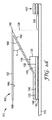
図1cは、本開示の別の態様に従い、第2接着層115で反射体110に取り付けられた第1コリメート光エンジン100を含む隣接した光エンジン101の側面図を示している。図1cの隣接した光エンジン101は、他の箇所で説明するように、光エンジンの連続生産に適合させることができる。他の箇所で説明するように、第1コリメート光エンジン100との位置関係を示すために、隣接した第2コリメート光エンジン100’の一部を示す。図1cで類似の数字を付けた要素は、図1aの類似の数字を付けた要素を指す。一実施形態では、成形加工されたバッフル170は、図に示すように放物線状の形を有し、反射体110に対して平行になるように光を部分的にコリメートするのに有用であり得る。成形加工されたバッフル170は、第1面172が光源130に向き、第2面174が第1面172の反対側にある反射性バッフルでもよい。第1面172及び第2面174の反射特性は、同じであっても異なっていてもよい。一実施形態では、第1面172及び第2面174のうちの少なくとも一方を、鏡面反射体、半鏡面反射体、及び拡散反射体から選択することができる。一実施形態では、バッフルはESRフィルムを含み、第1面172及び第2面174は共に同様の反射特性を有する。
FIG. 1 c shows a side view of an
成形加工されたバッフル170は、第3接着剤125でフレキシブル基板140に取り付けることができる。更に、成形加工されたバッフル170を取り付ける領域を広げるために、図1aに示すように第2接着層115がフレキシブル基板140を超えて張り出してもよい。移送領域155は、第1コリメート光エンジン100と第2コリメート光エンジン100’とを分離する。移送領域155の長さは、光源130からの光を反射体110の平面に平行な方向に混合するように選択することができる。一実施形態では、他の箇所で説明するように、コリメート光エンジン100及び100’を連続して反射体110上で作り、移送領域155で分離させることができる。コリメート光エンジンは、図1aに示すように、続いて第1接着層105で後方基板150に取り付けることができる。
The molded
図1dは、本開示の別の態様に従い、第2接着層115で反射体110に取り付けられた第1コリメート光エンジン100を含む隣接した光エンジン101の側面図を示している。図1dの隣接した光エンジン101は、他の箇所で説明するように、光エンジンの連続生産に適合させることができる。他の箇所で説明するように、第1コリメート光エンジン100との位置関係を示すために、隣接した第2コリメート光エンジン100’の一部を示す。図1dで類似の数字を付けた要素は、図1aの類似の数字を付けた要素を指す。一実施形態では、成形加工されたバッフル180は図1aのバッフル120に似ているが、端部186と188との間に更なる部材を有し、これにより光源130の縁部132で支えられている成形加工されたバッフル部材との間に角度θ1を形成する。成形加工されたバッフル180は、第1面182が光源130に面し、第2面184が第1面182の反対側にあり、第3面187が第1面182から切れ目なく連続し、第4面189が第2面184から切れ目なく連続する反射性バッフルであり得る。第1面から第4面182、184、187、189の反射特性は、同じであっても異なっていてもよい。一実施形態では、第1面から第4面182、184、187、189のうちの少なくとも1つを、鏡面反射体、半鏡面反射体、及び拡散反射体から選択することができる。一実施形態では、バッフルはESRフィルムを含み、第1面から第4面182、184、187、189は同様の反射特性を有する。
FIG. 1d shows a side view of an
成形加工されたバッフル180は、第3接着剤125でフレキシブル基板140に取り付けることができる。更に、第2接着層115は、成形加工されたバッフル180を取り付ける領域を広げるために、図1aに示すようにフレキシブル基板140を超えて張り出すことができる。移送領域155は、第1コリメート光エンジン100及び第2コリメート光エンジン100’を分離する。移送領域155の長さは、光源130からの光を反射体110の平面に平行な方向に混合するように選択することができる。一実施形態では、他の箇所で説明するように、コリメート光エンジン100及び100’を連続して反射体110上で作り、移送領域155で分離させることができる。コリメート光エンジンは、図1aに示すように、続いて第1接着層105で後方基板150に取り付けることができる。
The molded
図1eは、本開示の別の態様に従い、第2接着層115で反射体110に取り付けられた第1コリメート光エンジン100を含む隣接した光エンジン101の側面図を示している。図1eの隣接した光エンジン101は、他の箇所で説明するように、光エンジンの連続生産に適合させることができる。他の箇所で説明するように、第1コリメート光エンジン100との位置関係を示すために、隣接した第2コリメート光エンジン100’の一部を示す。図1eで類似の数字を付けた要素は、図1a及び図1dの類似の数字を付けた要素を指す。一実施形態では、図1dのコリメート光エンジンの、成形加工されたバッフル180の角度θ1を角度θ2に拡大し、端部186と188との間の追加部材の長さを短くしたものを、図1eに示す。一態様では、他の箇所で説明するように、成形加工されたバッフル180の端部186と188との間の追加部材は、反射体110に沿ってほぼ発光面135に向って進む光の向きを切り替えることができる。一実施形態では、他の箇所で説明するように、コリメート光エンジン100及び100’を連続して反射体110上で作り、移送領域155で分離させることができる。コリメート光エンジンは、図1aに示すように、続いて第1接着層105で後方基板150に取り付けることができる。
FIG. 1e shows a side view of an
図1fは、本開示の別の態様に従い、第2接着層115で反射体110に取り付けられたコリメート光エンジン100を含む光エンジン101の側面図を示している。第2コリメート光エンジン100’(図示せず)を、図1eと同様の方法でコリメート光エンジン100に隣接して配置することができる。図1fの光エンジン101は、他の箇所で説明するように、光エンジンの連続生産に適合させることができる。図1fで類似の数字を付けた要素は、図1a及び図1eの類似の数字を付けた要素を示す。一実施形態では、フレキシブル基板140の両端に光源130と130’及び回路145と145’を隣り合わせに取り付けたものを図1fに示す。フレキシブル基板140は、第2接着層115で反射体110に取り付けられている。光源130と130’の発光面135と135’は、反射体110に沿って逆方向に光を放射するように配置される。
FIG. 1 f shows a side view of a
一実施形態では、成形加工されたバッフル190は、例えばフィルムを折り畳む、又は硬い構造物を形成することにより作られた一体構造として形成できる。この実施形態では、第1面192は第3面197、第4面197’、第5面192’と切れ目なく連続し、第2面194は第6面199、第7面199’、第8面194’と切れ目なく連続する。成形加工されたバッフル190は、第1面192が光源130に面し、第2面194が第1面192の反対側にある反射性バッフルであり得る。第1面から第8面192、194、197、199、197’、199’、192’、194’の反射特性は、同じであっても異なっていてもよい。一実施形態では、第1面から第8面192、194、197、199、197’、199’、192’、194’のうちの少なくとも1つの面を鏡面反射体、半鏡面反射体、及び拡散反射体から選択することができる。一実施形態では、バッフルはESRフィルムを含み、第1面から第8面192、194、197、199、197’、199’、192’、194’は同様の反射特性を有する。一態様では、成形加工されたバッフル190の端部196、198、及び196’の間の追加部材は、所望の方向に光の向きを切り替えることができる。一実施形態では、反射体110に沿ってほぼ平行の方向に進んでいる第1光線161は、第2光線162によって示されるように、反射体110から概して離れる方向に向きを切り替えることができる。一実施形態では、他の箇所で説明するように、コリメート光エンジン100及び100’を連続して反射体110上で作り、移送領域155で分離させることができる。コリメート光エンジンは、図1aに示すように、続いて第1接着層105で後方基板150に取り付けることができる。
In one embodiment, the molded
図2は、本開示の別の態様に従い、コリメート光エンジン200の側面図を示す。図2のコリメート光エンジン200は、他の箇所で説明するように、光エンジンの連続生産に特に良好に適合させることができる。コリメート光エンジン200は、反射体210の第1面に隣接して取り付けられた光源230及び回路245を含む。光源230は、図1aの光源130を参照して説明されるように配置される。光源230はフレキシブル基板240から突出し、縁部232はバッフル220に接触し、このバッフルは反射体210から角度をなして離れて、出射孔228を形成する。
FIG. 2 illustrates a side view of a collimated
他の箇所で説明するように、複数のコリメート光エンジン200が配列をなす場合、反射体210の一部の上に張り出している移送領域155により、出射孔228を通過した放射光の更なる混合が可能となる。移送領域155は、図に示した通り、バッフルの端部226が出射孔228に沿って反射体210に投影された部分を超える反射体210の領域である。
As described elsewhere, when multiple collimated
コリメート光エンジン200は、例えばバックライト空洞内部などの他の表面にコリメート光エンジン200を取り付けやすくするために、反射体210に配置される第1接着層205を任意に含む。任意の接着層205は、含まれた場合、必要になるまで接着剤を保護する剥離ライナ(図示せず)を含むことができる。
The collimated
図2に示した一実施形態では、光源230及び回路245をフレキシブル基板240に配置することができ、続いてこの基板は第2接着層215で反射体210に取り付けられる。別の実施形態では、例えばめっき又は当該技術分野において既知の回路の被覆の方法で、回路245を直接反射体210に配置することができる。この実施形態では、フレキシブル基板240及び第2接着層215の代わりに、反射体に直接成形される回路の接着を改善することで知られる結合層を使用する。
In one embodiment shown in FIG. 2, the
バッフル220を光源230の上に配置する。バッフル220は、図1aの視覚φを参照して説明されているように、反射体210の一部の上に張り出している。一実施形態では、例えば反射体210を折り目217で折り畳んで、光源230の縁部232で支えられるバッフル220を形成するなど、バッフル220は反射体210と切れ目なく連続しており、同じ材料で形成される。別の実施形態では、バッフル220は、例えば熱、超音波、溶媒又は機械的な手段で、反射体210に折り目217で接合される。好ましい実施形態には、折り目217で折り畳むことにより形成される連続したバッフル220及び反射体210が含まれる。一実施形態(図示せず)では、第2光源は、第1光源に面して、移送領域に隣接して配置することができる。この実施形態では、第2光源の上に第2バッフルを配置することで、同一の反射体及び同一の移送領域を含み互いに面する、一対のコリメート光エンジンを得ることができる。
A
バッフル220は、第1面222が光源230に面し、第2面224が第1面222の反対側にある反射性バッフルであってよい。第1面222及び第2面224の反射特性は、同じであっても異なっていてもよい。一実施形態では、第1面222及び第2面224のうちの少なくとも1つの面を鏡面反射体、半鏡面反射体、及び拡散反射体から選択することができる。一実施形態では、バッフルはESRフィルムを含み、第1面222及び第2面224は共に同様の反射特性を有する。
The
バッフル220は、不均一な光学的又はその他の物理的な特性を有してもよい。一実施形態では、縁部232で支えられバッフルの端部226まで続く部分は、この部分の剛性を増すために高い曲げ弾性率を有するフィルムなどの材料を含むことができる。別の実施形態では、第1面222及び第2面224のうちの少なくとも一方の反射特性をバッフル全体にわたって変化させることができる。更に別の実施形態では、バッフル220においてバッフルの端部226に近い部分は、他の箇所で説明するように、鋸歯状、スリット、穿孔、エンボス加工、又は印刷されて、反射及び/又は透過特性を変更することができる。
The
図3a〜3gは、本開示の一態様に従い、コリメート光エンジンの生産プロセスの工程の一部を示している。図3a〜3gを参照して説明される一般的なプロセス工程は、連続して、又は段階的な方法で実施することができる。 Figures 3a-3g illustrate some of the steps of a production process for a collimated light engine according to one aspect of the present disclosure. The general process steps described with reference to FIGS. 3a-3g can be performed in a continuous or stepwise manner.
図3aは、発光面335を有する複数の光源330が光源配列336に並べられフレキシブル基板340上に配置されている様子を示している。任意の数の光源配列336に並べられた任意の数の光源330を、回路345と関連付けることができる。一実施形態では、フレキシブル基板340は、図に示した要素がロールの長さ方向に繰り返されるような、ロール状の材料などの連続基板でもよい。別の実施形態では、フレキシブル基板340は、図に示した要素がロールの幅の方向に繰り返されるような、ロール状の材料などの連続基板でもよい。
FIG. 3 a shows a state where a plurality of
回路345は、フレキシブル基板340に直接形成することができ、光源配列336に対処するように接続される。光源配列336は、同一の光源330を含むこともできるし、又は他の箇所で説明するように、異なる色のLED光源など、個々の光源330は異なっていてもよい。一実施形態では、個々の光源330を回路345で独立して制御することができる。一実施形態では、各光源配列336を回路345で独立して制御することができる。
The
図3bは、図3aの回路345、光源330及び縁部332、並びに発光面335を取り付けたフレキシブル基板340の側面図を示している。第3接着層315は、フレキシブル基板340の下面に適用される。図3bに示した物品は、続いて図3cに示したように、第3接着層315を反射体310の第1面と接触させることで反射体310に接着させることができる。第1接着層305は、反射体310の第2面に適用される。一実施形態では、第1接着層305は第3接着層315に接触する前に適用される。剥離ライナ(図示せず)は、第1接着層305の何も付いていない面を保護するのに使用できる。図3dは、反射体310及びフレキシブル基板340の一部の上を第2接着層325でコーティングした図3cの物品を示している。図3eでは、図3dの物品の上にバッフル320が配置され、図3fに示したように、ゴムローラー又はゴムシートなど適合する材料301を使用して、バッフル320を接着層325に押圧する。バッフル320は図3dの物品に接着し、バッフル320を光源330の縁部332と接触させて、端部326を上昇させることで出射孔328を形成する。
FIG. 3b shows a side view of the
図3gは、図1aに示したコリメート光エンジン100に類似したコリメート光エンジン300の完成品を示しており、類似の数字を付けた要素は対応している。一実施形態では、図3a〜3fに概略を示した手順をわずかに変えることで、図1a〜1fを参照して上述した任意のコリメート光エンジンを生産することができる。個々のコリメート光エンジンは、例えば移送領域155に隣接して切断することにより、連続したロールから分離させることができる。
FIG. 3g shows a finished product of a collimating
図2を参照して上述した実施形態に従ったコリメート光エンジンは、図3a〜fに類似した方法で、ただしより少ない工程で生産することができる。一実施形態では、図3a〜3bに示した工程に従い、図3bの物品が反射体310に接着される。反射体310は、続いて折り畳まれ、第1接着層305が図2に示すように適用される。別の実施形態では、図3aに示される工程を他の箇所で説明するように直接反射体310に施し、続いて反射体310を折り畳み第1接着層305を図2に示すように適用する。
The collimated light engine according to the embodiment described above with reference to FIG. 2 can be produced in a manner similar to FIGS. In one embodiment, the article of FIG. 3b is adhered to the
個々のコリメート光エンジンは、後方基板150に配列して接着することで、図4に示すと共に本願と同日付けに出願された同時係属中の「ILLUMINATION DEVICE WITH PROGRESSIVE INJECTION」なる名称の代理人整理番号63957US002で更に説明するように、任意の大きさ又は形状の照明素子を生産することができる。図4は、後方基板450に配置されたコリメート光エンジン400及び400’を含む照明素子401の斜視図を示している。コリメート光エンジン400は、後方基板450に取り付けられた反射体410、バッフル420、及び個々の光源430を含む光源配列436a〜dを含む。バッフルの端部426の反射体410に対する投影部が、隣接するコリメート光エンジン400と400’との間の移送領域455を画定する。移送領域455の大きさは、光エンジン間の光を所望の均一性にするために調整できる。コリメート光エンジン400’は、類似の構成要素(数字の隣にダッシュを入れている)を含み、図に示すように、照明素子の大きさを所望のように拡大するために更なる光エンジンを追加することができる。
The individual collimated light engines are arranged and bonded to the
図5は、中空の空洞502内の後方基板550に配置された一対のコリメート光エンジン500及び500’を有する中空のバックライト501内でのいくつかの代表的な光線の経路を示している。コリメート光エンジン500及び500’は、他の箇所で説明するように、それぞれバッフル520及び520’、バッフルの縁部526及び526’、出射孔528及び528’、第1面524及び524’、並びに第2面522及び522’を含む。光線AB、AC、AD、AE及びAFは、第1コリメート光エンジン500内に配置された光源530により、中空の空洞502に入射する。図5は、光源530がバッフル520と反射性基板510との間に配置され、中空の空洞502の長さにほぼ沿った方向に光を入射する様子を示している。一実施形態では、光源530は、反射性基板510により画定される平面の下に位置することができ、光を中空の空洞の長さに対してほぼ垂直に入射させて、バッフル520で反射させ、中空の空洞(図示せず)の長さに沿って方向転換させるように配置させることができる。
FIG. 5 illustrates some exemplary ray paths in a
光源530は、白色光を表面から半球状に放射できるように光を低変換する蛍光体を備えた青色又は紫外線放射LEDなどの表面放射LED、又は他の箇所で説明するように他のものにすることができる。表面放射LEDの場合、第1光線ABはバッフル520の第2面522で反射し、出射孔528を通過して透過性前方フィルム540に向って方向付けられる。第2光線ACは、出射孔528を通過し、反射することなく透過性前方フィルム540に向って方向付けられる。第3光線ADは、出射孔528を通過し、(第2コリメート光エンジン500’の)バッフル520’の第1面524’で反射し、透過性前方フィルム540に向って方向付けられる。第4光線AEは、第1コリメート光エンジン500内の反射性基板510で反射し、出射孔528を通過し、透過性前方フィルム540に向って方向付けられる。第5光線AFは、出射孔528を通過し、移送領域555内の背面反射体で反射し、(第2コリメート光エンジン500’の)バッフル520’の第1面524’で反射し、透過性前方フィルム540に向って方向付けられる。図5に示るように、AB、AC、AD、AE、AFの各光線は、出力面546を通して中空のバックライト501から出る前に、付加的な光学フィルム544を通過してもよい。バッフル520及び520’は、第1光源530からの光線が中空の空洞502内を横断面560に近い角度θの範囲内にとどまって進むように配置されている。横断面560は、中空のバックライト501の出力面546にほぼ平行であり、θは横断面560から平均偏差角度以内で0〜40度、又は0〜30度、又は0〜15度の範囲である。コリメート光エンジン500’の第2光源530’から放射される光線(図示せず)は、上述した経路と同様の経路を進むことができる。
The
図5は、光入射装置から入射された光が、透過性前方フィルム540に方向付けられる前に様々な反射を遂げる様子を示している。透過性前方フィルム540は、バックライトの出力面に適したフィルムであればどのようなものでもよく、これには部分的に透過性の前方反射体、拡散フィルム、半鏡面反射体、これらの組み合わせ、又は、本願と同日付けで出願された同時係属中の「ILLUMINATION DEVICE WITH PROGRESSIVE INJECTION」なる名称の代理人整理番号63957US002などで説明されているようなその他の好適なフィルムが挙げられる。中空の空洞502内での異なる表面との相互作用の組み合わせにより、光の均質化が行われ、その結果、不均一性が最小限に抑えられる。更に、移送領域555は、更なる混合を可能にし光源間の物理的な分離距離を広げるのを可能にする機能を果たす。中空の空洞内に設置されたバッフルは、LED光源を出力面546から「隠す」役目を果たし、他の箇所で説明するように光源の直視を妨げる。移送領域の長さが増すに従い、中空の空洞内の放射束が低下し、結果的に照明装置の輝度が低下する。少なくともこの理由により、追加の入射孔から累進的により多くの光を入射して放射束を増大させ、バックライトの使用可能な長さを伸ばすことが可能である。
FIG. 5 shows how the light incident from the light incident device undergoes various reflections before being directed to the transmissive
中空の空洞内の1カ所以上に光センサ599を配置して光の強度を監視することができ、光源の1つ又はいくつかを、例えば帰還回路で調整することができる。光の強度制御は、手動でも自動でもよく、照明装置の様々な領域の光出力を独立して制御するのに使用できる。
The
フィルム系コリメート光エンジン
各々高さ0.6mm、長さ1.3mmの一連の側面放射型の白色LED(日亜化学株式会社から入手可能なNichia NSSW006T型LED)を、発光面が幅11.7mmのフレックス回路の縁部と揃うように実装した。実装された一連のLEDは、図3aに示される構成に対応する(7つの直列のLEDの3つの並列バンク)。フレックス回路は、幅28.6mmのESRフィルムストリップ(3M社)に接着され、その結果、発光面はESRフィルムの前縁から10mm、フレックス回路の反対側の縁部はESRフィルムの後縁から約6.8mmであった。ESRフィルムの後縁から約13.7mmに接着剤を塗布し、フレックス回路の約6.8mmを覆い、ESRフィルムの第2のストリップを接着剤に押圧し、図3gに示されるものと同様のコリメート光エンジンを作製した。この図において、ESRフィルムの第1のストリップは反射体310に、ESRフィルムの第2のストリップはバッフル32に対応する。この結果生じたフィルム系コリメート光エンジンの出射孔は2.2mm、全長は約29mmであった。この結果生じた楔のアスペクト比(反射体310上での出射孔328の高さの、LED縁部332の高さに対する比率)は約2:1であった。
Film-based collimated light engine A series of side-emitting white LEDs (Nichia NSSW006T type LEDs available from Nichia Corporation) each 0.6 mm in height and 1.3 mm in length, with a light-emitting surface width of 11.7 mm It was mounted to align with the edge of the flex circuit. The implemented series of LEDs corresponds to the configuration shown in FIG. 3a (3 parallel banks of 7 series LEDs). The flex circuit is glued to a 28.6 mm wide ESR film strip (3M Company) so that the light emitting surface is 10 mm from the leading edge of the ESR film and the opposite edge of the flex circuit is approximately from the trailing edge of the ESR film. It was 6.8 mm. Apply approximately 13.7 mm of adhesive from the trailing edge of the ESR film, cover approximately 6.8 mm of the flex circuit, press the second strip of ESR film against the adhesive, and similar to that shown in FIG. A collimated light engine was produced. In this figure, the first strip of ESR film corresponds to the
LEDの発光面(図3gの面335)とESR(反射体110)の前縁との間の距離は、LEDのピッチ間隔に左右される。すべて白色LEDの場合、この距離はLEDのピッチより大きいか、又はこれに等しいべきである。LEDの等間隔ピッチのRGBGのカラークラスタの場合、この距離はLEDのピッチの4倍より大きいか、又はこれに等しいべきである。コリメート光エンジンは、前もって厚さ101.6マイクロメートル(0.004インチ)のステンレス鋼のシムストックに積層されたESRフィルムのバックプレーンに接着された。
The distance between the light emitting surface of the LED (
実施例1:フィルム系入射装置の全光束
フィルム系光入射装置の全光束(TLF)は、Optronic積分球を用いて、楔を形成する上部ESRフィルムを剥がしてLEDを完全に露出させ、LEDが障害物なしに積分球に放射できるようにした上で測定された。7つのNichia NSSW006T型LED(直列)から成る3つの並列バンクは、全電流30mA及び定常状態電圧19.8Vで駆動された。電力消費量は全体で0.59ワットであった。TLFの測定値は49.94ルーメンであり、このTLF値は、光エンジンからの100%の理想的な発光を示すものであった。上部のESRフィルムは次に、元の位置に戻され、ESRのバックプレーン上の最大高さは約2.2mmであり、LEDの位置から2:1で広がる楔を形成した。この構成で測定されたTLFは47.95ルーメンであり、エンジンの効率が96%であることが示された。
Example 1 Total Luminous Flux of Film-Based Incident Device The total luminous flux (TLF) of a film-based light incident device uses an Optronic integrating sphere to peel off the upper ESR film that forms the wedge so that the LED is completely exposed. Measured after allowing the integrating sphere to radiate without obstruction. Three parallel banks of seven Nichia NSSW006T LEDs (in series) were driven with a total current of 30 mA and a steady state voltage of 19.8V. The total power consumption was 0.59 watts. The measured TLF was 49.94 lumens, and this TLF value showed 100% ideal emission from the light engine. The top ESR film was then returned to its original position, and the maximum height on the ESR backplane was about 2.2 mm, forming a wedge that spread 2: 1 from the LED location. The TLF measured with this configuration was 47.95 lumens, indicating an engine efficiency of 96%.
指示がない限り、本明細書及び請求項で使用される特徴である大きさ、量、及び物理特性を示すすべての数字は、「約」と言う用語によって修飾されることを理解されたい。それ故に、別の指示がない限りは、本明細書及び添付の請求項に説明される数字のパラメータは近似値であり、本明細書に開示された教示を使用して当業者が獲得しようとする所望の特性に応じて変化し得る。 Unless otherwise indicated, it is to be understood that all numbers indicating the size, quantity, and physical characteristics that are features used in the specification and claims are modified by the term “about”. Therefore, unless otherwise indicated, the numerical parameters set forth in this specification and the appended claims are approximations, and will be obtained by one of ordinary skill in the art using the teachings disclosed herein. It can vary depending on the desired characteristics.
本願で引用したすべての参照文献及び刊行物は、本開示と完全には矛盾することのない程度まで、そのすべてが引用によって本開示に明白に組み込まれる。本明細書において特定の実施形態が例示及び説明されてきたが、多様な代替及び/又は同等の実施が、本開示の範囲から逸脱することなく、図示され説明された特定の実施形態と置き換えられ得ることは、当業者には理解されるであろう。本出願は、本明細書で説明された特定の実施形態のいかなる翻案又は変形をも包含すべく意図されている。したがって、本開示が特許請求の範囲及びその同等物によってのみ限定されることを、意図するものである。本発明の実施態様の一部を以下の項目1−37に列記する。
〔1〕
第1面を有する反射体と、
前記第1面に隣接して取り付けられた光源及び回路と、
前記光源が、前記反射体に対する法線から50度未満の角度からは見えないように、前記光源の上に配置され前記反射体の一部の上に張り出しているバッフルと、
を備える、コリメート光エンジン。
〔2〕
前記光源が、前記反射体の前記第1面にほぼ平行な放射光軸を有する、項目1に記載のコリメート光エンジン。
〔3〕
前記光源が、前記反射体に対する法線から60度未満の角度からは見えない、項目1に記載のコリメート光エンジン。
〔4〕
前記反射体が、鏡面反射体又は半鏡面反射体である、項目1に記載のコリメート光エンジン。
〔5〕
前記反射体が多層干渉反射体である、項目1に記載のコリメート光エンジン。
〔6〕
前記反射体及び前記バッフルのうちの少なくとも一方が光学干渉層を含む、項目1に記載のコリメート光エンジン。
〔7〕
前記反射体及び前記バッフルのうちの少なくとも一方が銀を含む、項目1に記載のコリメート光エンジン。
〔8〕
前記光源及び回路が回路化基板に配置され、前記回路化基板が前記反射体に取り付けられた、項目1に記載のコリメート光エンジン。
〔9〕
前記回路化基板が可撓性である、項目8に記載のコリメート光エンジン。
〔10〕
前記バッフルの第1面が前記光源に向き、第2面が前記第1面と反対側を向き、前記第1面及び第2面のうちの少なくとも一方が光を反射する、項目1に記載のコリメート光エンジン。
〔11〕
前記光源から放射された光が、前記反射体に平行な横断面の30度以内に部分的にコリメートされる、項目1に記載のコリメート光エンジン。
〔12〕
前記光源がLEDを含む、項目1に記載のコリメート光エンジン。
〔13〕
前記LEDがコリメートレンズを更に含む、項目12に記載のコリメート光エンジン。
〔14〕
前記LEDが、有色LED、白色LED、及びこれらの組み合わせから成る群から選択される、項目12に記載のコリメート光エンジン。
〔15〕
前記LEDが、前記反射体に対する法線を中心に360度未満の角度広がりで光を放射することができる、項目12に記載のコリメート光エンジン。
〔16〕
前記バッフル及び前記反射体が、一体型の折り畳まれたフィルムを含む、項目1に記載のコリメート光エンジン。
〔17〕
前記バッフルが、接着剤により前記光源の上に取り付けられている、項目1に記載のコリメート光エンジン。
〔18〕
前記反射体の前記第1面にほぼ平行な放射光軸を有するように、前記第1面に隣接して取り付けられており、第1光源の方向に向いている、第2光源及び回路と、
前記反射体に対する法線から50度未満の角度からは前記第2光源が見えないように、前記第2光源の上に配置され前記反射体の一部の上に張り出しているバッフルと、
を更に備える、項目1に記載のコリメート光エンジン。
〔19〕
前記第2光源が、前記反射体に対する法線から60度未満の角度からは見えない、項目18に記載のコリメート光エンジン。
〔20〕
項目1に記載のコリメート光エンジンを備える、バックライト。
〔21〕
複数のコリメート光エンジンが、硬い基板の上で前記放射光軸に平行な方向に沿って配置されている、項目20に記載のバックライト。
〔22〕
前記複数のコリメート光エンジンの各々が独立して制御可能な、項目21に記載のバックライト。
〔23〕
前記コリメート光エンジンと光通信する光センサを更に備える、項目20に記載のバックライト。
〔24〕
項目20に記載のバックライトを備える、照明装置。
〔25〕
項目1に記載のコリメート光エンジンを備える、照明器具。
〔26〕
項目1に記載のコリメート光エンジンを備える、タスクライト。
〔27〕
項目1に記載のコリメート光エンジンを備える、光源。
〔28〕
反射体を提供する工程と、
平面回路化基板に実装され、前記平面回路化基板にほぼ平行な放射光軸を有する光源を提供する工程と、
前記反射体を形成してバッフル及び背面反射体を提供する工程であって、前記バッフルが、前記背面反射体の一部の上に張り出している、工程と、
前記バッフルが、前記背面反射体に対する法線から50度未満の角度からは前記光源を見えなくするように、前記バッフルと前記背面反射体との間に前記平面回路化基板を取り付ける工程と、
を含む、コリメート光エンジンを作製する方法。
〔29〕
前記バッフルが、前記背面反射体に対する法線から60度未満の角度からは前記光源を見えなくする、項目28に記載の方法。
〔30〕
反射体を提供する工程と、
平面回路基板に実装され、前記平面回路化基板にほぼ平行な放射光軸を有する光源を提供する工程と、
前記反射体に前記平面回路基板を取り付ける工程と、
バッフルを提供する工程と、
前記光源の上に前記バッフルを取り付けて、前記反射体に対する法線から50度未満の角度からは前記光源を見えなくする、工程と、
を含み、前記バッフルが、前記反射体の一部の上に張り出している、コリメート光エンジンを作製する方法。
〔31〕
前記バッフルが、前記背面反射体に対する法線から60度未満の角度からは前記光源を見えなくする、項目30に記載の方法。
〔32〕
反射体を提供する工程と、
前記反射体上に回路を形成する工程と、
前記反射体に対してほぼ平行な放射光軸を有する光源を前記回路に取り付ける工程と、
前記反射体を形成してバッフル及び背面反射体を提供する工程であって、前記バッフルが、前記回路及び光源を含む前記背面反射体の一部の上に張り出している、工程と、
を含み、
前記バッフルが、前記背面反射体に対する法線から50度未満の角度からは前記光源を見えなくすることができる、
コリメート光エンジンを作製する方法。
〔33〕
前記バッフルが、前記背面反射体に対する法線から60度未満の角度からは前記光源を見えなくする、項目32に記載の方法。
〔34〕
前記平面回路化基板が可撓性である、項目28又は項目30に記載の方法。
〔35〕
前記反射体がロールで提供される、項目28、項目30又は項目32に記載の方法。
〔36〕
前記形成工程及び取り付け工程が連続して実施される、項目28、項目30又は項目32に記載の方法。
〔37〕
項目28、項目30又は項目32に記載の方法で生産されたコリメート光エンジンのロール。
All references and publications cited in this application are expressly incorporated by reference into this disclosure to the extent that they do not completely contradict the disclosure. While specific embodiments have been illustrated and described herein, various alternative and / or equivalent implementations can be substituted for the specific embodiments illustrated and described without departing from the scope of the present disclosure. It will be appreciated by those skilled in the art. This application is intended to cover any adaptations or variations of the specific embodiments described herein. Therefore, it is intended that this disclosure be limited only by the claims and the equivalents thereof. Some of the embodiments of the present invention are listed in the following item 1-37.
[1]
A reflector having a first surface;
A light source and circuit mounted adjacent to the first surface;
A baffle disposed over the light source and projecting over a portion of the reflector such that the light source is not visible from an angle less than 50 degrees from a normal to the reflector;
A collimated light engine.
[2]
Item 2. The collimated light engine of
[3]
Item 2. The collimated light engine of
[4]
Item 2. The collimated light engine according to
[5]
Item 2. The collimated light engine of
[6]
The collimated light engine of
[7]
The collimated light engine of
[8]
The collimated light engine according to
[9]
Item 9. The collimated light engine of item 8, wherein the circuitized substrate is flexible.
[10]
[11]
Item 2. The collimated light engine of
[12]
Item 2. The collimated light engine of
[13]
The collimating light engine of item 12, wherein the LED further comprises a collimating lens.
[14]
13. The collimated light engine of item 12, wherein the LED is selected from the group consisting of a colored LED, a white LED, and combinations thereof.
[15]
Item 13. The collimated light engine of item 12, wherein the LED is capable of emitting light with an angular spread of less than 360 degrees about a normal to the reflector.
[16]
The collimating light engine of
[17]
The collimating light engine of
[18]
A second light source and a circuit mounted adjacent to the first surface so as to have a radiation optical axis substantially parallel to the first surface of the reflector and facing the direction of the first light source;
A baffle disposed on the second light source and projecting over a portion of the reflector so that the second light source cannot be seen from an angle less than 50 degrees from the normal to the reflector;
The collimated light engine according to
[19]
Item 19. The collimated light engine of item 18, wherein the second light source is not visible from an angle less than 60 degrees from the normal to the reflector.
[20]
A backlight comprising the collimating light engine according to
[21]
Item 21. The backlight of item 20, wherein a plurality of collimated light engines are arranged on a rigid substrate along a direction parallel to the radiation optical axis.
[22]
Item 22. The backlight of item 21, wherein each of the plurality of collimated light engines is independently controllable.
[23]
Item 21. The backlight of item 20, further comprising an optical sensor in optical communication with the collimated light engine.
[24]
A lighting device comprising the backlight according to item 20.
[25]
A lighting fixture comprising the collimated light engine according to
[26]
A task light comprising the collimated light engine according to
[27]
A light source comprising the collimated light engine according to
[28]
Providing a reflector;
Providing a light source mounted on a planar circuit board and having a radiation optical axis substantially parallel to the planar circuit board;
Forming the reflector to provide a baffle and a back reflector, the baffle overhanging a portion of the back reflector;
Attaching the planar circuitized substrate between the baffle and the back reflector such that the baffle makes the light source invisible from an angle less than 50 degrees from a normal to the back reflector;
A method for making a collimated light engine.
[29]
29. A method according to item 28, wherein the baffle makes the light source invisible from an angle less than 60 degrees from a normal to the back reflector.
[30]
Providing a reflector;
Providing a light source mounted on a planar circuit board and having a radiation optical axis substantially parallel to the planar circuit board;
Attaching the planar circuit board to the reflector;
Providing a baffle;
Attaching the baffle over the light source to make the light source invisible from an angle less than 50 degrees from the normal to the reflector;
And the baffle overhangs over a portion of the reflector.
[31]
32. The method of item 30, wherein the baffle makes the light source invisible from an angle less than 60 degrees from a normal to the back reflector.
[32]
Providing a reflector;
Forming a circuit on the reflector;
Attaching a light source having a radiation axis substantially parallel to the reflector to the circuit;
Forming the reflector to provide a baffle and a back reflector, the baffle overhanging a portion of the back reflector including the circuit and a light source;
Including
The baffle can make the light source invisible from an angle less than 50 degrees from the normal to the back reflector;
A method of making a collimated light engine.
[33]
33. A method according to item 32, wherein the baffle makes the light source invisible from an angle less than 60 degrees from a normal to the back reflector.
[34]
31. A method according to item 28 or item 30, wherein the planar circuitized substrate is flexible.
[35]
33. A method according to item 28, item 30 or item 32, wherein the reflector is provided in a roll.
[36]
The method according to Item 28, Item 30, or Item 32, wherein the forming step and the attaching step are performed continuously.
[37]
A roll of collimated light engine produced by the method of item 28, item 30 or item 32.
Claims (4)
前記第1面に隣接して取り付けられた光源及び回路と、
前記光源が、前記反射体に対する法線から50度未満の角度からは見えないように、前記光源の上に前記光源と接触して配置され前記反射体の一部の上に張り出して中空の光コリメート楔を形成しているバッフルと、
を備え、前記反射体及び前記バッフルの少なくとも1つが半鏡面反射体を含む、コリメート光エンジン。 A reflector having a first surface;
A light source and circuit mounted adjacent to the first surface;
The light source is placed on the light source in contact with the light source so that the light source cannot be seen from an angle less than 50 degrees from the normal to the reflector, and projects over a part of the reflector to provide hollow light. A baffle forming a collimating wedge ;
A collimated light engine , wherein at least one of the reflector and the baffle comprises a semi-specular reflector .
Applications Claiming Priority (3)
| Application Number | Priority Date | Filing Date | Title |
|---|---|---|---|
| US6122508P | 2008-06-13 | 2008-06-13 | |
| US61/061,225 | 2008-06-13 | ||
| PCT/US2009/044102 WO2009151869A2 (en) | 2008-06-13 | 2009-05-15 | Collimating light engine |
Publications (3)
| Publication Number | Publication Date |
|---|---|
| JP2011523195A JP2011523195A (en) | 2011-08-04 |
| JP2011523195A5 JP2011523195A5 (en) | 2012-06-28 |
| JP5390604B2 true JP5390604B2 (en) | 2014-01-15 |
Family
ID=41417338
Family Applications (1)
| Application Number | Title | Priority Date | Filing Date |
|---|---|---|---|
| JP2011513531A Expired - Fee Related JP5390604B2 (en) | 2008-06-13 | 2009-05-15 | Collimated light engine |
Country Status (7)
| Country | Link |
|---|---|
| US (1) | US8608362B2 (en) |
| EP (1) | EP2300871B1 (en) |
| JP (1) | JP5390604B2 (en) |
| KR (1) | KR101571919B1 (en) |
| CN (1) | CN102089702B (en) |
| TW (1) | TWI453355B (en) |
| WO (1) | WO2009151869A2 (en) |
Families Citing this family (22)
| Publication number | Priority date | Publication date | Assignee | Title |
|---|---|---|---|---|
| US8469575B2 (en) * | 2007-05-20 | 2013-06-25 | 3M Innovative Properties Company | Backlight and display system using same |
| WO2008144650A1 (en) * | 2007-05-20 | 2008-11-27 | 3M Innovative Properties Company | Collimating light injectors for edge-lit backlights |
| CN101681053B (en) * | 2007-05-20 | 2012-03-21 | 3M创新有限公司 | Recycling backlights with semi-specular components |
| WO2008147753A2 (en) * | 2007-05-20 | 2008-12-04 | 3M Innovative Properties Company | White light backlights and the like with efficient utilization of colored led sources |
| US8523419B2 (en) * | 2007-05-20 | 2013-09-03 | 3M Innovative Properties Company | Thin hollow backlights with beneficial design characteristics |
| CN101939675A (en) | 2008-02-07 | 2011-01-05 | 3M创新有限公司 | Hollow backlight with structured film |
| CN101952646B (en) * | 2008-02-22 | 2014-01-29 | 3M创新有限公司 | Backlights having selected output light flux distributions and display systems using same |
| US8378661B1 (en) * | 2008-05-29 | 2013-02-19 | Alpha-Omega Power Technologies, Ltd.Co. | Solar simulator |
| EP2297607B1 (en) * | 2008-06-04 | 2014-04-23 | 3M Innovative Properties Company | Hollow backlight with tilted light source |
| CN102089703B (en) * | 2008-06-13 | 2013-10-16 | 3M创新有限公司 | Illumination device with progressive injection |
| KR20160105527A (en) | 2008-07-10 | 2016-09-06 | 쓰리엠 이노베이티브 프로퍼티즈 컴파니 | Viscoelastic lightguide |
| EP2321677A4 (en) * | 2008-08-08 | 2011-08-17 | 3M Innovative Properties Co | Lightguide having a viscoelastic layer for managing light |
| US9709242B2 (en) | 2010-09-23 | 2017-07-18 | Light Prescriptions Innovators, Llc | Shell integrator |
| WO2012063728A1 (en) * | 2010-11-10 | 2012-05-18 | シャープ株式会社 | Lighting device and display device |
| WO2013065116A1 (en) * | 2011-10-31 | 2013-05-10 | 日立コンシューマエレクトロニクス株式会社 | Backlight device and liquid crystal display device utilizing same |
| CN103133918B (en) | 2011-11-23 | 2015-11-11 | 财团法人工业技术研究院 | Surface light source and flexible surface light source |
| WO2013080344A1 (en) * | 2011-11-30 | 2013-06-06 | 日立コンシューマエレクトロニクス株式会社 | Backlight device and liquid-crystal display device using same |
| RU2660381C2 (en) | 2013-06-27 | 2018-07-06 | Филипс Лайтинг Холдинг Б.В. | Lighting device |
| CN106062475B (en) * | 2014-01-06 | 2019-06-21 | 光处方革新有限公司 | Shell integrator |
| US10161593B2 (en) | 2014-02-25 | 2018-12-25 | 3M Innovative Properties Company | Solid state lighting device with virtual filament(s) |
| US9046637B1 (en) | 2014-02-25 | 2015-06-02 | 3M Innovative Properties Company | Tubular lighting systems with inner and outer structured surfaces |
| EP3537037A1 (en) * | 2018-03-09 | 2019-09-11 | Teknoluks Endustriyel Metal Ve Plastik San. Tic. Ltd. Sti. | Lighting system based on sight blocking and multiple reflection for point and directional light sources |
Family Cites Families (46)
| Publication number | Priority date | Publication date | Assignee | Title |
|---|---|---|---|---|
| US5882774A (en) * | 1993-12-21 | 1999-03-16 | Minnesota Mining And Manufacturing Company | Optical film |
| US6080467A (en) * | 1995-06-26 | 2000-06-27 | 3M Innovative Properties Company | High efficiency optical devices |
| JPH09226043A (en) * | 1996-02-26 | 1997-09-02 | Mitsui Toatsu Chem Inc | Reflector |
| JP3442581B2 (en) * | 1996-08-06 | 2003-09-02 | 株式会社ヒューネット | Driving method of nematic liquid crystal |
| JP3472417B2 (en) | 1996-10-22 | 2003-12-02 | シャープ株式会社 | Side-emitting chip LED and liquid crystal display |
| US6007209A (en) * | 1997-03-19 | 1999-12-28 | Teledyne Industries, Inc. | Light source for backlighting |
| JP3229250B2 (en) * | 1997-09-12 | 2001-11-19 | インターナショナル・ビジネス・マシーンズ・コーポレーション | Image display method in liquid crystal display device and liquid crystal display device |
| US6870523B1 (en) * | 2000-06-07 | 2005-03-22 | Genoa Color Technologies | Device, system and method for electronic true color display |
| US6655810B2 (en) * | 2000-06-21 | 2003-12-02 | Fujitsu Display Technologies Corporation | Lighting unit |
| JP3481599B2 (en) * | 2000-07-14 | 2003-12-22 | 京都電機器株式会社 | Linear lighting device |
| US7268223B2 (en) * | 2000-09-22 | 2007-09-11 | Wyeth | Isolated nucleic acid molecules which encode a soluble IL-TIF receptor or binding protein which binds to IL-TIF/IL-22, and uses thereof |
| US7776615B2 (en) * | 2001-04-20 | 2010-08-17 | Gl Sciences, Inc. | Method for solid-phase micro extraction and apparatus therefor |
| JP3972680B2 (en) * | 2001-06-21 | 2007-09-05 | ソニー株式会社 | Lighting optical unit, liquid crystal projector |
| TWI231874B (en) * | 2002-01-15 | 2005-05-01 | Chi Mei Optoelectronics Corp | Liquid crystal display having high brightness and wide viewing angle |
| JP2004095390A (en) * | 2002-08-30 | 2004-03-25 | Fujitsu Display Technologies Corp | Lighting device and display device |
| TW589467B (en) * | 2002-09-27 | 2004-06-01 | Litek Opto Electronics Co Ltd | Light collimating system |
| US7182480B2 (en) * | 2003-03-05 | 2007-02-27 | Tir Systems Ltd. | System and method for manipulating illumination created by an array of light emitting devices |
| JP2005157059A (en) * | 2003-11-27 | 2005-06-16 | Seiko Epson Corp | Illuminating apparatus and projector |
| DE102004046696A1 (en) * | 2004-05-24 | 2005-12-29 | Osram Opto Semiconductors Gmbh | Method for assembling a surface luminous system and surface luminous system |
| KR20050121076A (en) * | 2004-06-21 | 2005-12-26 | 삼성전자주식회사 | Back light assembly and display device having the same |
| KR100576870B1 (en) * | 2004-08-11 | 2006-05-10 | 삼성전기주식회사 | Nitride semiconductor light emitting diode and method of producing the same |
| US7304425B2 (en) * | 2004-10-29 | 2007-12-04 | 3M Innovative Properties Company | High brightness LED package with compound optical element(s) |
| US20060187650A1 (en) * | 2005-02-24 | 2006-08-24 | 3M Innovative Properties Company | Direct lit backlight with light recycling and source polarizers |
| US7478919B2 (en) * | 2005-03-21 | 2009-01-20 | Gamasonic Ltd. | Lamp strip assembly |
| US7311431B2 (en) * | 2005-04-01 | 2007-12-25 | Avago Technologies Ecbu Ip Pte Ltd | Light-emitting apparatus having a plurality of adjacent, overlapping light-guide plates |
| US20060221610A1 (en) | 2005-04-01 | 2006-10-05 | Chew Tong F | Light-emitting apparatus having a plurality of overlapping panels forming recesses from which light is emitted |
| CN1851536A (en) * | 2005-04-22 | 2006-10-25 | 鸿富锦精密工业(深圳)有限公司 | Backlight module and its optical film shaping method |
| TWI258044B (en) * | 2005-06-01 | 2006-07-11 | Au Optronics Corp | Direct-type backlight unit structure |
| US7903194B2 (en) * | 2005-06-24 | 2011-03-08 | 3M Innovative Properties Company | Optical element for lateral light spreading in back-lit displays and system using same |
| KR100667817B1 (en) | 2005-09-26 | 2007-01-11 | 삼성전자주식회사 | Backlight unit of direct light type and color filterless liquid crystal display apparatus employing the same |
| KR100784090B1 (en) * | 2005-10-25 | 2007-12-10 | 엘지이노텍 주식회사 | light emitting module and backlight unit having the same |
| WO2007049373A1 (en) * | 2005-10-27 | 2007-05-03 | Sharp Kabushiki Kaisha | Light source, and display and television receiver both using the same |
| US20070139961A1 (en) * | 2005-12-19 | 2007-06-21 | Cheah Chun H | Method and apparatus employing a heat sink, a flexible printed circuit conformed to at least part of the heat sink, and a light source attached to the flexible printed circuit |
| US7525126B2 (en) * | 2006-05-02 | 2009-04-28 | 3M Innovative Properties Company | LED package with converging optical element |
| US7736044B2 (en) * | 2006-05-26 | 2010-06-15 | Avago Technologies General Ip (Singapore) Pte. Ltd. | Indirect lighting device for light guide illumination |
| JP4857945B2 (en) * | 2006-06-21 | 2012-01-18 | ソニー株式会社 | Planar light source device and liquid crystal display device assembly |
| US20080019114A1 (en) | 2006-07-19 | 2008-01-24 | Gert Stuyven | Light source having enhanced mixing |
| WO2008013072A1 (en) * | 2006-07-25 | 2008-01-31 | Showa Denko K.K. | Light emitting device and display device using same |
| JP2008034273A (en) * | 2006-07-31 | 2008-02-14 | E Image Technology Kk | Reflector for direct backlight |
| TWI336799B (en) * | 2006-08-23 | 2011-02-01 | Lite On Technology Corp | Light guide device and light guide plate using the same |
| US20080049445A1 (en) * | 2006-08-25 | 2008-02-28 | Philips Lumileds Lighting Company, Llc | Backlight Using High-Powered Corner LED |
| US7834424B2 (en) * | 2006-09-12 | 2010-11-16 | The Board Of Trustees Of The Leland Stanford Junior University | Extendable connector and network |
| WO2008032275A1 (en) * | 2006-09-15 | 2008-03-20 | Koninklijke Philips Electronics N.V. | Flat and thin led-based luminary |
| WO2008047284A2 (en) * | 2006-10-16 | 2008-04-24 | Koninklijke Philips Electronics N.V. | Flat and thin led-based luminary |
| KR101565934B1 (en) * | 2008-05-23 | 2015-11-06 | 삼성디스플레이 주식회사 | Back-light assembly and display apparatus having the back-light assembly |
| CN102089703B (en) * | 2008-06-13 | 2013-10-16 | 3M创新有限公司 | Illumination device with progressive injection |
-
2009
- 2009-05-15 CN CN200980126639.1A patent/CN102089702B/en not_active Expired - Fee Related
- 2009-05-15 JP JP2011513531A patent/JP5390604B2/en not_active Expired - Fee Related
- 2009-05-15 KR KR1020117000539A patent/KR101571919B1/en not_active IP Right Cessation
- 2009-05-15 WO PCT/US2009/044102 patent/WO2009151869A2/en active Application Filing
- 2009-05-15 EP EP09763160.0A patent/EP2300871B1/en not_active Not-in-force
- 2009-05-15 US US12/996,409 patent/US8608362B2/en not_active Expired - Fee Related
- 2009-06-01 TW TW098118071A patent/TWI453355B/en not_active IP Right Cessation
Also Published As
| Publication number | Publication date |
|---|---|
| US8608362B2 (en) | 2013-12-17 |
| KR101571919B1 (en) | 2015-11-25 |
| WO2009151869A3 (en) | 2010-03-04 |
| KR20110030549A (en) | 2011-03-23 |
| TW201002987A (en) | 2010-01-16 |
| CN102089702B (en) | 2014-05-14 |
| WO2009151869A2 (en) | 2009-12-17 |
| EP2300871A4 (en) | 2012-03-07 |
| EP2300871A2 (en) | 2011-03-30 |
| CN102089702A (en) | 2011-06-08 |
| WO2009151869A8 (en) | 2011-02-10 |
| US20110075398A1 (en) | 2011-03-31 |
| JP2011523195A (en) | 2011-08-04 |
| EP2300871B1 (en) | 2016-03-09 |
| TWI453355B (en) | 2014-09-21 |
Similar Documents
| Publication | Publication Date | Title |
|---|---|---|
| JP5390604B2 (en) | Collimated light engine | |
| JP5457440B2 (en) | Lighting device with gradual injection | |
| US7402940B2 (en) | Surface light emitting apparatus | |
| US7537374B2 (en) | Edge-lit backlight having light recycling cavity with concave transflector | |
| US7661862B2 (en) | LCD display backlight using elongated illuminators | |
| JP2006286638A (en) | Light emitting device having a plurality of light guide plates adjoining each other and overlapping | |
| JP2004206916A (en) | Planar light source | |
| JP2009506501A (en) | Direct type backlight with light source for bifunctional spectrometer | |
| JP4635863B2 (en) | Surface emitting device | |
| JPWO2020101038A1 (en) | Surface lighting device | |
| US20070025098A1 (en) | Backlight assembly and liquid crystal display having the same | |
| US20110032449A1 (en) | Perforated backlight | |
| TWI622732B (en) | Illumination unit and display apparatus using the same | |
| US10534219B2 (en) | Array of point light sources contained within segmented reflective partitions | |
| KR101797593B1 (en) | Backlight unit and display device including the same | |
| JP2009211915A (en) | Planar light source | |
| KR101700791B1 (en) | Display device | |
| CN111830745A (en) | Backlight module and display device | |
| KR20120017155A (en) | Backlight unit and display device including the same | |
| JP2010175641A (en) | Backlight unit and liquid crystal display device including the same |
Legal Events
| Date | Code | Title | Description |
|---|---|---|---|
| A521 | Written amendment |
Free format text: JAPANESE INTERMEDIATE CODE: A523 Effective date: 20120511 |
|
| A621 | Written request for application examination |
Free format text: JAPANESE INTERMEDIATE CODE: A621 Effective date: 20120511 |
|
| A977 | Report on retrieval |
Free format text: JAPANESE INTERMEDIATE CODE: A971007 Effective date: 20130516 |
|
| A131 | Notification of reasons for refusal |
Free format text: JAPANESE INTERMEDIATE CODE: A131 Effective date: 20130521 |
|
| A521 | Written amendment |
Free format text: JAPANESE INTERMEDIATE CODE: A523 Effective date: 20130820 |
|
| TRDD | Decision of grant or rejection written | ||
| A01 | Written decision to grant a patent or to grant a registration (utility model) |
Free format text: JAPANESE INTERMEDIATE CODE: A01 Effective date: 20130910 |
|
| A61 | First payment of annual fees (during grant procedure) |
Free format text: JAPANESE INTERMEDIATE CODE: A61 Effective date: 20131010 |
|
| R150 | Certificate of patent or registration of utility model |
Free format text: JAPANESE INTERMEDIATE CODE: R150 |
|
| R250 | Receipt of annual fees |
Free format text: JAPANESE INTERMEDIATE CODE: R250 |
|
| R250 | Receipt of annual fees |
Free format text: JAPANESE INTERMEDIATE CODE: R250 |
|
| LAPS | Cancellation because of no payment of annual fees |