JP5386544B2 - Electron beam exposure apparatus and electron beam exposure method - Google Patents
Electron beam exposure apparatus and electron beam exposure method Download PDFInfo
- Publication number
- JP5386544B2 JP5386544B2 JP2011127213A JP2011127213A JP5386544B2 JP 5386544 B2 JP5386544 B2 JP 5386544B2 JP 2011127213 A JP2011127213 A JP 2011127213A JP 2011127213 A JP2011127213 A JP 2011127213A JP 5386544 B2 JP5386544 B2 JP 5386544B2
- Authority
- JP
- Japan
- Prior art keywords
- electron beam
- main deflection
- sub
- deflection
- main
- Prior art date
- Legal status (The legal status is an assumption and is not a legal conclusion. Google has not performed a legal analysis and makes no representation as to the accuracy of the status listed.)
- Active
Links
Images


Classifications
-
- H—ELECTRICITY
- H01—ELECTRIC ELEMENTS
- H01J—ELECTRIC DISCHARGE TUBES OR DISCHARGE LAMPS
- H01J37/00—Discharge tubes with provision for introducing objects or material to be exposed to the discharge, e.g. for the purpose of examination or processing thereof
- H01J37/02—Details
- H01J37/04—Arrangements of electrodes and associated parts for generating or controlling the discharge, e.g. electron-optical arrangement, ion-optical arrangement
- H01J37/147—Arrangements for directing or deflecting the discharge along a desired path
-
- B—PERFORMING OPERATIONS; TRANSPORTING
- B82—NANOTECHNOLOGY
- B82Y—SPECIFIC USES OR APPLICATIONS OF NANOSTRUCTURES; MEASUREMENT OR ANALYSIS OF NANOSTRUCTURES; MANUFACTURE OR TREATMENT OF NANOSTRUCTURES
- B82Y10/00—Nanotechnology for information processing, storage or transmission, e.g. quantum computing or single electron logic
-
- B—PERFORMING OPERATIONS; TRANSPORTING
- B82—NANOTECHNOLOGY
- B82Y—SPECIFIC USES OR APPLICATIONS OF NANOSTRUCTURES; MEASUREMENT OR ANALYSIS OF NANOSTRUCTURES; MANUFACTURE OR TREATMENT OF NANOSTRUCTURES
- B82Y40/00—Manufacture or treatment of nanostructures
-
- H—ELECTRICITY
- H01—ELECTRIC ELEMENTS
- H01J—ELECTRIC DISCHARGE TUBES OR DISCHARGE LAMPS
- H01J37/00—Discharge tubes with provision for introducing objects or material to be exposed to the discharge, e.g. for the purpose of examination or processing thereof
- H01J37/30—Electron-beam or ion-beam tubes for localised treatment of objects
- H01J37/317—Electron-beam or ion-beam tubes for localised treatment of objects for changing properties of the objects or for applying thin layers thereon, e.g. for ion implantation
- H01J37/3174—Particle-beam lithography, e.g. electron beam lithography
- H01J37/3177—Multi-beam, e.g. fly's eye, comb probe
-
- H—ELECTRICITY
- H01—ELECTRIC ELEMENTS
- H01J—ELECTRIC DISCHARGE TUBES OR DISCHARGE LAMPS
- H01J2237/00—Discharge tubes exposing object to beam, e.g. for analysis treatment, etching, imaging
- H01J2237/04—Means for controlling the discharge
- H01J2237/043—Beam blanking
- H01J2237/0435—Multi-aperture
- H01J2237/0437—Semiconductor substrate
-
- H—ELECTRICITY
- H01—ELECTRIC ELEMENTS
- H01J—ELECTRIC DISCHARGE TUBES OR DISCHARGE LAMPS
- H01J2237/00—Discharge tubes exposing object to beam, e.g. for analysis treatment, etching, imaging
- H01J2237/30—Electron or ion beam tubes for processing objects
- H01J2237/317—Processing objects on a microscale
- H01J2237/3175—Lithography
- H01J2237/31752—Lithography using particular beams or near-field effects, e.g. STM-like techniques
- H01J2237/31754—Lithography using particular beams or near-field effects, e.g. STM-like techniques using electron beams
-
- H—ELECTRICITY
- H01—ELECTRIC ELEMENTS
- H01J—ELECTRIC DISCHARGE TUBES OR DISCHARGE LAMPS
- H01J2237/00—Discharge tubes exposing object to beam, e.g. for analysis treatment, etching, imaging
- H01J2237/30—Electron or ion beam tubes for processing objects
- H01J2237/317—Processing objects on a microscale
- H01J2237/3175—Lithography
- H01J2237/31774—Multi-beam
Description
本発明は、電子ビーム露光装置及び電子ビーム露光方法に関し、特に複数のコラムセルで露光処理を並列して行うマルチコラム型の電子ビーム露光装置及び電子ビーム露光方法に関する。 The present invention relates to an electron beam exposure apparatus and an electron beam exposure method, and more particularly to a multi-column electron beam exposure apparatus and an electron beam exposure method that perform exposure processing in parallel in a plurality of column cells.
近年、半導体ウェハ上のパターンの描画に、マスクが不要で微細なパターンを精度よく描画できる電子ビーム露光装置が用いられている。このような電子ビーム露光装置の一つとして、電子ビームを照射するコラムセルを複数設け、露光を並列して行うことで描画速度を向上させたマルチコラム型の電子ビーム露光装置がある。 In recent years, an electron beam exposure apparatus capable of accurately drawing a fine pattern without using a mask has been used for drawing a pattern on a semiconductor wafer. As one of such electron beam exposure apparatuses, there is a multi-column type electron beam exposure apparatus in which a plurality of column cells for irradiating an electron beam are provided and exposure speed is improved by performing exposure in parallel.
このマルチコラム型の電子ビーム露光装置は、制御部に各コラムセルを制御するためのデータ(個別露光データ)を生成するスケジューリングソフトが格納されている。このスケジューリングソフトにより、制御部は設計データに基づいてウェハ全体の露光データを生成し、その露光データを各コラムセルが担当する領域毎に切り分ける。そして、実際のコラムセルの位置に応じて、切り分けられた露光データを再編集して個別露光データを生成する。 In this multi-column type electron beam exposure apparatus, scheduling software for generating data (individual exposure data) for controlling each column cell is stored in the control unit. With this scheduling software, the control unit generates exposure data for the entire wafer based on the design data, and divides the exposure data for each area that each column cell is responsible for. Then, according to the actual position of the column cell, the divided exposure data is re-edited to generate individual exposure data.
しかし、従来の電子ビーム露光装置では露光データの再編集に時間がかかり、迅速に露光を行えないという問題がある。 However, the conventional electron beam exposure apparatus has a problem that it takes time to re-edit the exposure data, and the exposure cannot be performed quickly.
そこで、各コラムセルの露光データをより迅速に生成できる電子ビーム露光装置及び電子ビーム露光方法を提供することを目的とする。 Accordingly, an object of the present invention is to provide an electron beam exposure apparatus and an electron beam exposure method that can generate exposure data of each column cell more quickly.
一観点によれば、試料を一定方向に往復移動させるステージと、前記試料に電子ビームを照射する複数のコラムセルと、前記コラムセル内に設けられ、前記電子ビームを偏向させて主偏向領域内で前記電子ビームの照射位置を制御する主偏向器と、前記コラムセル内に設けられ、前記電子ビームを偏向させて前記主偏向領域よりも狭い副偏向領域内で前記電子ビームの照射位置を制御する副偏向器と、前記主偏向領域に含まれる前記各副偏向領域への電子ビームの照射の順序を定めた副偏向領域データを生成するスケジューリング部とを備えた電子ビーム露光装置であって、前記スケジューリング部は、コラムセルの位置が設計値通りであるものとして配置された前記主偏向領域に隣接する主偏向領域を結合して結合主偏向領域を生成するスタティック部と、前記コラムセルの実際の位置に基づいて前記主偏向領域の位置を修正した修正主偏向領域を求め、該修正主偏向領域と前記結合主偏向領域との重複部分に含まれる前記副偏向領域のデータを集めて副偏向領域データを生成するダイナミック部と、を有する電子ビーム露光装置が提供される。 According to one aspect, a stage that reciprocates the sample in a fixed direction, a plurality of column cells that irradiate the sample with an electron beam, and a column cell that is provided in the column cell and deflects the electron beam in the main deflection region. The main deflector for controlling the irradiation position of the electron beam and the column deflector provided in the column cell for deflecting the electron beam to control the irradiation position of the electron beam in a sub-deflection area narrower than the main deflection area. An electron beam exposure apparatus comprising: a sub-deflector that generates a sub-deflection area data that defines an irradiation order of the electron beam to each sub-deflection area included in the main deflection area; The scheduling unit generates a combined main deflection region by combining main deflection regions adjacent to the main deflection region arranged so that column cell positions are as designed. A corrected main deflection area in which the position of the main deflection area is corrected based on an actual position of the tick part and the column cell is obtained, and the sub-element included in the overlapping portion of the corrected main deflection area and the combined main deflection area An electron beam exposure apparatus having a dynamic unit that collects deflection area data and generates sub deflection area data is provided.
また、別の一観点によれば、試料を一定方向に往復移動させるステージと、前記試料に電子ビームを照射する複数のコラムセルと、前記コラムセル内に設けられ、前記電子ビームを偏向させて主偏向領域内で前記電子ビームの照射位置を制御する主偏向器と、前記コラムセル内に設けられ、前記電子ビームを偏向させて前記主偏向領域よりも狭い副偏向領域内で前記電子ビームの照射位置を制御する副偏向器と、前記主偏向領域に含まれる前記各副偏向領域への電子ビームの照射の順序を定めた副偏向領域データを生成するスケジューリング部とを備えた電子ビーム露光装置を用いる電子ビーム露光方法であって、各コラムセルの位置が設計通りの位置にあるものとして前記主偏向領域を配置する工程と、前記主偏向領域に隣接する他の主偏向領域と結合して結合主偏向領域を生成する工程と、前記コラムセルの実際の位置に基づいて前記主偏向領域の位置を修正した修正主偏向領域を求める工程と、前記結合主偏向領域と前記修正主偏向領域との重複部分に含まれる副偏向領域を集めて副偏向領域データを生成する工程と、を有する電子ビーム露光方法が提供される。 According to another aspect, a stage for reciprocating the sample in a fixed direction, a plurality of column cells for irradiating the sample with an electron beam, and a column cell provided in the column cell for deflecting the electron beam A main deflector for controlling the irradiation position of the electron beam in the main deflection region and a column deflector provided in the column cell for deflecting the electron beam in a sub-deflection region narrower than the main deflection region. An electron beam exposure apparatus comprising: a sub-deflector that controls the irradiation position; and a scheduling unit that generates sub-deflection area data that defines the order of irradiation of the electron beam to each sub-deflection area included in the main deflection area An electron beam exposure method using the step of disposing the main deflection region on the assumption that the position of each column cell is as designed, and another main bias adjacent to the main deflection region. Combining a region to generate a combined main deflection region; obtaining a corrected main deflection region in which the position of the main deflection region is corrected based on an actual position of the column cell; and An electron beam exposure method comprising: collecting sub-deflection areas included in an overlapping portion with the corrected main deflection area and generating sub-deflection area data.
上記観点の電子ビーム露光装置では、スケジューリング部において、コラムセルの位置が設計上の位置にあるものとして配置された主偏向領域に、隣接する主偏向領域を結合して結合主偏向領域を生成する。そして、ダイナミック部で、実際のコラムセルの位置に基づいて主偏向領域の位置を修正した修正主偏向領域を求め、その修正主偏向領域と重なる副偏向領域を、前記結合主偏向領域から所定の順番で検出する。これにより、修正主偏向領域内で連続するように副偏向領域が並んだ副偏向領域データが得られる。 In the electron beam exposure apparatus according to the above aspect, the scheduling unit generates a combined main deflection region by combining adjacent main deflection regions with a main deflection region arranged so that the column cell is located at a designed position. . Then, in the dynamic portion, a corrected main deflection area in which the position of the main deflection area is corrected based on the actual column cell position is obtained, and a sub deflection area overlapping with the corrected main deflection area is determined from the combined main deflection area by a predetermined amount. Detect in order. Thereby, sub deflection area data in which the sub deflection areas are arranged so as to be continuous in the corrected main deflection area is obtained.
そのため、副偏向領域データ内で、副偏向領域の順番が修正主偏向領域内で連続するように並べなおす必要がなくなり、各コラムセルの個別露光データをより迅速に生成できる。 Therefore, it is not necessary to rearrange the sub-deflection areas so that the order of the sub-deflection areas is continuous in the corrected main deflection area, and the individual exposure data of each column cell can be generated more quickly.
以下、本発明の実施形態の説明に先立って、本願発明者らがこれまでに行なってきた各コラムセルの露光データの生成方法について説明する。 Prior to the description of the embodiments of the present invention, a method for generating exposure data for each column cell, which has been performed so far by the present inventors, will be described.
図1は、電子ビーム露光装置のブロック図である。 FIG. 1 is a block diagram of an electron beam exposure apparatus.
図1のように、電子ビーム露光装置1は、複数のコラムセル11を備えた電子ビームコラム10と、電子ビームコラム10を制御する制御部20とに大別される。このうち、制御部20は、電子銃高圧電源21、レンズ電源22、バッファメモリ23、ステージ駆動コントローラ24及びステージ位置センサ25を有している。
As shown in FIG. 1, the electron
電子銃高圧電源21は、電子ビームコラム10内の各コラムセル11の電子銃を駆動させるための高電圧を発生させる。レンズ電源22は、電子ビームコラム10の各コラムセル11内の電磁レンズに駆動電流を供給する。バッファメモリ23は、コラムセル11の数に対応する分だけ用意されている。バッファメモリ23は、統合制御系26から送出された各コラムセル11の制御データである個別露光データを格納する。そして、この個別露光データの順序に従って、各ショットの露光条件を読みだしてコラムセル11に転送する。ステージ駆動コントローラ24は、ステージ位置センサ25からの位置情報に基づいて、ウェハ12を移動させる。
The electron gun high-
このような、制御部20の各部21〜24は、ワークステーション等よりなる統合制御系26によって制御される。また、統合制御系26は、入力された設計データを基に各コラムセル11の露光動作を制御する個別露光データを生成する。
一方、電子ビームコラム10は、同等なコラムセル11を複数、例えば8本備えている。そして、各コラムセル11の下には、ウェハ12を搭載するウェハステージ13が配置されている。
On the other hand, the
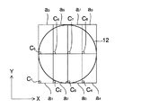
図2は、ウェハ12上で各コラムセル11が描画を行う領域を示す平面図である。図示のように、各コラムセル11は、符号C1〜C8の位置にそれぞれ配置され、それぞれが矩形状の領域a 1 〜a 8 の露光を行う。
FIG. 2 is a plan view showing an area where each
図3は、図1の電子ビーム露光装置1のコラムセル11のブロック図である。
FIG. 3 is a block diagram of the
図3のように、コラムセル11は露光部100と、露光部100を制御するコラムセル制御部31とに大別される。このうち、露光部100は電子ビーム生成部130と、マスク偏向部140と、基板偏向部150とを備えている。
As shown in FIG. 3, the
電子ビーム生成部130では、電子銃101から放出された電子を第1電磁レンズ102で収束させて、所定の電流密度の電子ビームEBとする。この電子ビームEBは、ビーム整形用マスク103の矩形アパーチャ103aを通過することで断面形状が矩形状に整形される。
In the electron
その後、電子ビームEBは、マスク偏向部140の第2電磁レンズ105の収束作用を受けた後、第1静電偏向器104及び第2静電偏向器106で偏向されて、露光マスク110の所定のパターンSiに結像される。露光マスク110の上下に配置された第3電磁レンズ108及び第4電磁レンズ111は、電子ビームEBをウェハ上で結像させる役割を果たす。
Thereafter, the electron beam EB is subjected to the convergence action of the second
電子ビームEBは、露光マスク110を通過することで断面形状がパターンSiの形状に整形される。なお、第1静電偏向器104及び第2静電偏向器106の偏向範囲(ビーム偏向範囲)を超える部分にあるパターンSiを使用する場合には、マスクステージ123で露光マスク110を移動させる。
Electron beam EB is a cross-sectional shape by passing through an
露光マスク110を通った電子ビームEBは、第3静電偏向器112及び第4静電偏向器113によって光軸Cに振り戻された後、第5電磁レンズ114によってそのサイズが縮小される。マスク偏向部140の静電偏向器104、106、112、113で発生する電子ビームEBの偏向収差は、第1補正コイル107及び第2補正コイル109によって補正される。
The electron beam EB that has passed through the
その後、電子ビームEBは、基板偏向部150の遮蔽板115の円形の開口部(アパーチャ)115aを通過し、第5静電偏向器(副偏向器)119及び電磁偏向器(主偏向器)120によってウェハ12上の所定の位置に偏向される。主偏向器120では、比較的広い範囲での電子ビームの偏向が行なわれ、副偏向器119では主偏向器120よりも狭い範囲内でより高速な電子ビームの偏向が行われる。これらの偏向器119、120で生じる電子ビームEBの偏向収差は、第3補正コイル117及び第4補正コイル118によって補正される。また、第1投影用電磁レンズ116及び第2投影用電磁レンズ121は、ウェハ12の表面に電子ビームEBを結像させる役割を果たす。
Thereafter, the electron beam EB passes through a circular opening (aperture) 115 a of the
一方、コラムセル制御部31は、電子銃制御部202と、電子光学系制御部203と、マスク偏向制御部204と、マスクステージ制御部205と、ブランキング制御部206と基板偏向制御部207とを有する。これらのうち、電子銃制御部202は電子銃101を制御して、電子ビームEBの加速電圧等のビーム放射条件を制御する。また、電子光学系制御部203は、電磁レンズ102、105、108、111、114、116及び121へ供給する電流量を制御して、電子光学系の倍率や焦点位置を調整する。マスク偏向制御部204は、第1静電偏向器104及び第2静電偏向器106に印加する電圧を制御して露光マスク110上の所望のパターンSiに電子ビームEBを導く。
On the other hand, the column
ブランキング制御部206は、ブランキング電極127へ印加する電圧を制御して、電子ビームEBを所定の露光時間(ショット時間)の間だけ、遮蔽板115のアパーチャ115aを通過させて、ウェハ12の表面に電子ビームEBを照射する時間を制御する。基板偏向制御部207は、第5静電偏向器(副偏向器)119に印加する電圧と、電磁偏向器(主偏向器)120に供給する電流量を制御して、ウェハ12の所望の位置に電子ビームEBを偏向させる。
The blanking
上記のコラムセル制御部31の各部202〜207は、統合制御系26から送出された個別露光データに基づいて動作する。
The
次に、上記の電子ビーム露光装置1の露光動作について説明する。ここに、図4は、電子ビーム露光装置1の露光動作を説明する図である。
Next, the exposure operation of the electron
電子ビーム露光装置1は、ステージ13で図4の矢印Aに示すようにY方向へ連続的に移動させながらウェハ12の露光を行う。各コラムセル11の主偏向器120は、矢印Bに示すように、電子ビームの偏向位置を行方向(X方向)及び列方向(Y方向)に順次移動させながら、副偏向領域42に電子ビームを照射してゆく。
The electron
主偏向器120の偏向位置が所定の副偏向領域42に位置する間に、副偏向器119による電子ビームEBの偏向が行われ、その副偏向領域42内の各ショットの露光が行われる。これにより、副偏向領域42内にパターン31が描画される。1つの副偏向領域42内の全ショットが完了すると、主偏向器120は電子ビームの偏向位置を次の副偏向領域へ移動させる。
While the deflection position of the
このようにして、各コラムセル11でステージ13の連続移動方向(往復移動方向)に延びる帯状の領域(フレーム)の露光を繰り返し行う。
In this way, the exposure of the band-like region (frame) extending in the continuous movement direction (reciprocating movement direction) of the
上記の露光動作は、下記の露光データに基づいて行われる。ここに、図5は、全てのコラムセルに対する露光データを含んだ全体露光データの構造を示す図である。 The above exposure operation is performed based on the following exposure data. FIG. 5 is a diagram showing the structure of overall exposure data including exposure data for all column cells.
図5のように、全体露光データは、チップ単位の露光データであるBEF(Block Exposure File)40と、これらのBEF40のウェハ12上での配置を規定するレイアウトデータとを含む。各BEF40には、部分拡大図に示すように複数の主偏向領域41が含まれ、それらの主偏向領域41の各々には複数の副偏向領域42が含まれている。なお、主偏向領域41は、主偏向器120で電子ビームEBを偏向可能な領域に対応し、副偏向領域42は副偏向器119で電子ビームEBを偏向可能な領域に対応している。
As shown in FIG. 5, the overall exposure data includes BEF (Block Exposure File) 40 that is exposure data in units of chips, and layout data that defines the arrangement of these BEFs 40 on the
さらに、各副偏向領域42のショットデータは図6に示される。図6のように、ショットデータは、ビームの偏向位置(x、y)、ビームサイズ(又はビームのパターン形状)及び露光時間といった各ショットの条件がショットの順番に並べられている。
Further, the shot data of each
次に、各コラムセル11の露光を制御する個別露光データの生成方法について説明する。
Next, a method for generating individual exposure data for controlling the exposure of each
図7は、統合制御系26に設けられたスケジューリング部27のブロック図である。
FIG. 7 is a block diagram of the
図7に示すように、スケジューリング部27は、入力された設計データ80に基づいて、BEF40及びその配置を示すレイアウトデータ39とを含む全体露光データ81を生成する。そして全体露光データ81を、スタティック部28及びダイナミック部29で個別露光データ82に変換する。
As shown in FIG. 7, the
以下、本願発明者らがこれまでに行っていた個別露光データの生成方法とその問題点について説明する。 Hereinafter, the method of generating individual exposure data and the problems that have been performed so far by the present inventors will be described.
(本願発明者らがこれまでに行っていた個別露光データの生成方法)
図8は、本願発明者らがこれまでに行っていた個別露光データの生成方法におけるスタティック部28の動作を説明するフローチャートである。
(Generation method of individual exposure data that the present inventors have performed so far)
FIG. 8 is a flowchart for explaining the operation of the
図8のステップS11において、スタティック部28は、入力されたBEF40とレイアウトデータとに基づいて、各コラムセル11が露光を行う領域にBEF40を配置する。ここでは、スタティック部28は各コラムセル11の位置が設計上の位置にあるものとしてBEF40の位置座標を決定する。
In step S11 of FIG. 8, the
次に、ステップS12で、スタティック部28は、複数のBEF40から、ステージ13の連続移動方向(Y方向)に並んだ複数の主偏向領域41を集めてフレームを生成する。1つのコラムセル11は、複数のフレームにわたって露光する。このようにして、全体露光データがフレームを基準にして各コラムセル11用の露光データに分割される。このステップS12により、例えば図9に示すようなフレーム44が生成される。
Next, in step S <b> 12, the
次に、ステップS13(図8参照)において、スタティック部28は各主偏向領域41に含まれる副偏向領域42のデータを集めた副偏向領域データを生成する。この副偏向領域データ内の副偏向領域42の順番は、各主偏向領域41内で主偏向器120が各副偏向領域42に電子ビームEBを偏向する順番を規定している。すなわち副偏向領域データは、主偏向器120の動作を制御する制御データとなっている。副偏向領域データは、各主偏向領域41に1つずつ作成される。
Next, in step S <b> 13 (see FIG. 8), the
次に、ステップS14において、副偏向領域データに含まれる副偏向領域42の順番を主偏向領域41内での位置が連続するように並べなおす。
Next, in step S14, the order of the
図10は、図8のステップS13、S14で生成された副偏向領域データの一例を示す図である。なお、図10の副偏向領域42に付された数字は、副偏向領域データの中での副偏向領域42の順番を表している。
FIG. 10 is a diagram illustrating an example of the sub deflection region data generated in steps S13 and S14 of FIG. The numbers given to the
図示のような並びとすることで、主偏向器120による電子ビームEBの照射位置の移動を効率良く行える。
By arranging as shown in the drawing, the irradiation position of the electron beam EB by the
その後、上記のステップS13及びS14(図8参照)を、各コラムセル11が露光を行う領域に含まれる全ての主偏向領域41に対して行なう(ループ1)。全ての主偏向領域41についてステップS13及びS14の処理が完了すると、ステップS15に移行する。
Thereafter, the above steps S13 and S14 (see FIG. 8) are performed on all the
次のステップS15において、スタティック部28は、各副偏向領域42で行われる各ショットのショット条件を集めてショットデータを生成し、スタティック部28による処理を終了する。
In the next step S <b> 15, the
上記のようにして、スタティック部28ではフレーム、副偏向領域データ、及びショットデータが生成される。
As described above, the
ただし、スタティック部28で生成された露光データは、各コラムセル11が設計上の位置にあるものと仮定して求めたものであり、そのまま利用することはできない。すなわち、電子ビーム露光装置1の筐体は、気圧や温度の変動によって変形し、各コラムセル11の位置は経時的に変化する。そのため、スタティック部28で生成された露光データをそのまま用いて各コラムセル11で露光を行うと、露光位置がずれてしまう。
However, the exposure data generated by the
そこで、スケジューリング部27のダイナミック部29により、実際のコラムセルの位置に合わせてスタティック部28で生成した露光データを再編集する。
Therefore, the
図11は、本願発明者らがこれまでに行っていた個別露光データの生成方法におけるダイナミック部29の動作を説明するフローチャートである。
FIG. 11 is a flowchart for explaining the operation of the
まず、図11のステップS21において、ダイナミック部29はスタティック部28で配置された全てのBEF40に含まれる主偏向領域41のテーブルTmaを生成する。
First, in step S <b> 21 of FIG. 11, the
次のステップS22において、ダイナミック部29はコラムセル11の実際の位置に基づいて位置を修正した修正主偏向領域51を配置し、その修正主偏向領域51のテーブルTmbを生成する。
In the next step S22, the
図12は、ダイナミック部29で配置された修正主偏向領域51とスタティック部28で配置された主偏向領域41とを示す図である。図示のように、修正主偏向領域51は、コラムセル11の位置C 2 の位置ずれ量Δuだけ、主偏向領域41からずれた位置に配置される。なお、図12では、修正主偏向領域51を1フレーム(フレーム54)分のみ示しているが、ステップS22では全ての主偏向領域41をカバーするように修正主偏向領域51を配置する。
FIG. 12 is a diagram showing a corrected
次に、ステップS23(図11参照)においてダイナミック部29は、テーブルTmaの中の主偏向領域41で、修正主偏向領域51と重複する主偏向領域41を検出し、検出した主偏向領域41を集めたリストLmbを生成する。
Next, in step S23 (see FIG. 11), the
図13は、修正主偏向領域51と重なる領域の抽出方法を説明する図である。図13の場合には、修正主偏向領域51と重なる主偏向領域41をテーブルTma(図12参照)の中から探索する。そして、修正主偏向領域51と重なる主偏向領域41a、41b、41c、41dからなるリストLmbが生成される。
FIG. 13 is a diagram for explaining a method for extracting an area overlapping with the corrected
次に、ステップS24(図12参照)に移行して、ダイナミック部29は、リストLmbに含まれる主偏向領域41の副偏向領域42が、修正主偏向領域51に入っているか否かを判断する。ステップS24において、副偏向領域42が修正主偏向領域51に入っていると判断した場合(Yes)には、ステップS25に移行して、リストLsmaに検出された副偏向領域42を追加する。一方、ステップS24で副偏向領域42が修正主偏向領域51に入っていないと判断した場合(No)には、リストLsmaにその副偏向領域42は追加しない。
Next, the process proceeds to step S24 (see FIG. 12), and the
その後、ステップS24、S25の処理を、主偏向領域41に含まれるすべての副偏向領域42に対して繰り返す(ループ3)。また、このループ3をリストLmbに含まれるすべての主偏向領域41に対して繰り返す(ループ2)。
Thereafter, the processes in steps S24 and S25 are repeated for all the
以上のループ3及びループ2により、図13の修正主偏向領域51に入っている副偏向領域42のデータを集めたリストLsma(副偏向領域データ)が完成する。
By the
図14(a)は、並び変えを行う前のリストLsmaに含まれる副偏向領域の順番を示している。図14(a)のように、リストLsmaの中では、ループ2、ループ3で検出した順番で副偏向領域42が並んでいる。そのため、リストLsmaを、そのまま修正主偏向領域51の副偏向領域データとして用いると、矢印に示すように主偏向器120による電子ビームEBの移動量(ジャンプベクトル)が大きくなり、偏向整定待ち時間が発生して電子ビームEBの移動を効率良く行えない。
FIG. 14A shows the order of the sub-deflection areas included in the list Lsma before rearrangement. As shown in FIG. 14A, in the list Lsma, the
そこで、ステップS26(図12参照)に移行して、ダイナミック部29はリストLsmaの中の副偏向領域42を、修正主偏向領域51の中で連続するように並べなおす。
Therefore, the process proceeds to step S26 (see FIG. 12), and the
図14(b)、(c)は、図14(a)のリストLsma内の副偏向領域42の順番の並べ直し方を説明する図である。並べ直す前のリストLsma内での副偏向領域42は、図14(b)の上段のように並ぶ。ステップS26において、リストLsmaの中の副偏向領域42の位置座標を検出してその位置座標に基づいて図14(b)の下段のように並べ直す。その結果、図14(c)のように、修正主偏向領域51の中で副偏向領域42が行方向に往復しつつ列方向に1行ずつ移動して連続するように並ぶ。これにより、修正主偏向領域51に対応する副偏向領域データが完成する。
14B and 14C are diagrams for explaining how to rearrange the order of the
その後、テーブルTmbに含まれるすべての修正主偏向領域51についてS23〜S26までの処理を繰り返して(ループ1)各修正主偏向領域51について副偏向領域データを生成し、ダイナミック部29の処理が完了する。
Thereafter, the processes from S23 to S26 are repeated for all the corrected
上記のようにして、実際のコラムセル11の位置に応じて設定された修正主偏向領域51及びその副偏向領域データを含む個別露光データが得られる。
As described above, the individual exposure data including the corrected
ところで、上記の説明では、理解を容易にするために1つのBEF(チップ)40がそれぞれ4つの主偏向領域を含むものを示したが、一般には、より多くの主偏向領域が含まれる。 By the way, in the above description, in order to facilitate understanding, one BEF (chip) 40 includes four main deflection areas, but generally includes more main deflection areas.
例えば、主偏向領域の大きさは約100μm角程度であるのに対し、1つのチップのサイズが33mm×26mmである場合には、1つのBEFに含まれる主偏向領域41の数は85800(=330×260)程度となる。この場合、1つのコラムセル11が5行×2列=10個のBEF40の露光を行うとすると、1つのコラムセルの個別露光データの生成のために、ダイナミック部29は、858000(=10×85800)個の修正主偏向領域51及びその副偏向領域データを生成する。そのため、図11のループ1の処理が858000回繰り返し行われる。
For example, when the size of the main deflection area is about 100 μm square, and the size of one chip is 33 mm × 26 mm, the number of
また、図示の例では簡単のために主偏向領域41に含まれる副偏向領域42の数を16個としたが、実際にはより多く、主偏向領域41には約100個の副偏向領域42が含まれる。そのため、図14(b)のようなダイナミック部29での副偏向領域42の並べ替えもより複雑となる。
In the illustrated example, the number of
さらに、上記の処理をコラムセル11の本数分である8本分行うと、本願発明者らがこれまでに行っていた個別露光データの生成方法では、個別露光データの生成に10時間程度の時間を要し、迅速に個別露光データを生成できないという問題があった。
Further, when the above process is performed for eight
上記の問題に鑑み、本願発明者らは、下記に説明する本発明の第1の実施形態に係る個別露光データの生成方法を着想した。 In view of the above problems, the present inventors have conceived a method for generating individual exposure data according to the first embodiment of the present invention described below.
(第1の実施形態)
図15は、第1の実施形態に係る個別露光データの生成方法におけるスタティック部28の動作を説明するフローチャートである。図16は、結合主偏向領域の生成方法を説明する図である。
(First embodiment)
FIG. 15 is a flowchart for explaining the operation of the
本実施形態では、まず図15のステップS31において、スタティック部28がレイアウトデータに基づいてBEF40を配置する。ここでは、各コラムセル11の位置が設計値通りであるものとしてBEF40の位置座標を決定する。
In the present embodiment, first, in step S31 of FIG. 15, the
次に、ステップS32に移行して、スタティック部28は、BEF40の中の各主偏向領域41a〜41dについて、隣接する主偏向領域41a〜41dを結合して結合主偏向領域61を生成する。例えば、コラムセル11の位置が設計上の位置に対して右方向にずれている場合には、図16のBEF40の左下の主偏向領域41aについては、その右側の主偏向領域41cと結合して結合主偏向領域61aを生成する。また、例えばBEF40の右下の主偏向領域41cのように、右隣に隣接する主偏向領域がない場合には、露光データを含まない空領域を作成して、その空領域を主偏向領域41cの右側から結合して結合主偏向領域61cを生成する。
Next, proceeding to step S <b> 32, the
一方、コラムセル11の位置が左方向にずれる場合には、左側に隣接する主偏向領域を結合すればよい。
On the other hand, when the position of the
このように、コラムセル11の位置ずれ方向に隣接する主偏向領域同士を結合することで、後のステップで実際のコラムセル11の位置に基づいて修正主偏向領域を設定した際に、修正主偏向領域が結合主偏向領域と重なり、副偏向領域42の抽出が容易になる。
In this way, the main deflection areas adjacent to each other in the direction of displacement of the
このステップS32の処理を、BEF40内の全ての主偏向領域41について繰り返す(ループ2)。これにより、図16のように、主偏向領域41a〜41dについて、それぞれ結合主偏向領域61a〜61dが生成される。
The process of step S32 is repeated for all the
その後、ループ2の処理(図15参照)を、全てのBEF40に含まれる主偏向領域に対して繰り返す(ループ1)。これにより、主偏向領域41a〜41dについて、それぞれ結合主偏向領域61a〜61dが生成される。
Thereafter, the processing of loop 2 (see FIG. 15) is repeated for the main deflection regions included in all the BEFs 40 (loop 1). Thereby, coupled
次に、ステップS33に移行して、スタティック部28は、結合主偏向領域61に含まれる副偏向領域42のデータを集めて結合副偏向領域データを生成する。
Next, the process proceeds to step S33, where the
次いで、ステップS34において、スタティック部28は、結合副偏向領域データ内の副偏向領域42の順番を、結合主偏向領域61a内で連続するように並べなおす。
Next, in step S34, the
図17は、第1の実施形態における結合副偏向領域データ内の副偏向領域42の並べなおし方を説明する図である。ステップS33で生成された結合副偏向領域データ内の副偏向領域42の並びは、図17(a)のように結合主偏向領域61内で不連続となっている。そこで、ステップS34で副偏向領域42を並べ直すことで、図17(b)のように、結合副偏向領域データの中の
副偏向領域42が結合主偏向領域61内で行方向に往復しつつ列方向に1行ずつ移動して連続するように並べなおす。
FIG. 17 is a diagram for explaining how to rearrange the
このステップS33及びS34を全ての結合主偏向領域に対して繰り返す(ループ3)ことにより、各結合主偏向領域について結合副偏向領域データを生成する。 By repeating steps S33 and S34 for all the coupled main deflection regions (loop 3), coupled sub deflection region data is generated for each coupled main deflection region.
その後、ステップS35に移行して、スタティック部28は、ステージ13の連続移動方向(Y方向)に並んだ複数の主偏向領域41を集めてフレーム44を生成する。
Thereafter, the process proceeds to step S <b> 35, and the
次いで、各副偏向領域42について、それぞれショット条件を集めたショットデータ46を生成し、スタティック部28の処理を終了する。
Next, for each
次に、ダイナミック部29による露光データの再編集を行う。ここに、図18は第1の実施形態に係る個別露光データ生成方法におけるダイナミック部29の動作を説明するフローチャートである。
Next, re-editing of exposure data by the
まず、ステップS41において、ダイナミック部29は、スタティック部28で設定した結合主偏向領域のデータを格納したテーブルTmaを生成する。続いて、ステップS42において、実際のコラムセル11の位置に基づいて修正主偏向領域を設定し、その修正主偏向領域のデータを格納したテーブルTmbを生成する。
First, in step S <b> 41, the
次に、ステップS43において、ダイナミック部29は、修正主偏向領域と重なる結合主偏向領域をリストアップするためのリストLmbと、修正主偏向領域と重なる副偏向領域42をリストアップするためのリストLsmaとを用意する。
Next, in step S43, the
次に、ステップS44において、テーブルTmaに含まれるいずれか1の修正主偏向領域を選び、この修正主偏向領域と重なる結合主偏向領域を検出して、検出された結合主偏向領域をリストLmbに格納する。このステップS44は、テーブルTmaに含まれる全ての主偏向領域に対して繰り返す(ループ1)。 Next, in step S44, any one of the corrected main deflection areas included in the table Tma is selected, a combined main deflection area overlapping with the corrected main deflection area is detected, and the detected combined main deflection area is displayed in the list Lmb. Store. This step S44 is repeated for all main deflection areas included in the table Tma (loop 1).
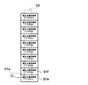
図19は、結合主偏向領域(実線枠)と修正主偏向領域51a(破線枠)とを示している。図19の一番下の修正主偏向領域51aに対して、結合主偏向領域61e、61fが重なる。したがって、ステップS44では、修正主偏向領域51aに対応するリストLmbに結合主偏向領域61e、61fを格納する。
FIG. 19 shows a combined main deflection area (solid line frame) and a corrected
次に、リストLmbに含まれる全ての結合主偏向領域に含まれる副偏向領域42について下記のステップS45及びS46の処理を繰り返すループ2及びループ3を行う。
Next,
ステップS45では、ダイナミック部29は、結合主偏向領域61e内の副偏向領域42が修正主偏向領域51aと重なるか否かを判断する。副偏向領域42が修正主偏向領域51aと重なるか否かの判断は、副偏向領域42及び修正主偏向領域51aの位置座標に基づいて行う。ステップS45で副偏向領域42が修正主偏向領域51aと重なっていると判断した場合(YES)には、ステップS46に移行して、その副偏向領域42をリストLsmaに格納する。また、副偏向領域42が修正主偏向領域51aと重ならない場合(NO)には、その副偏向領域42はリストLsmaに格納しない。
In step S45, the
図20は、上記のステップS45、S46の処理を説明する図である。まず、図20のように、結合主偏向領域61eの左下の副偏向領域42について、修正主偏向領域51aと重なるか否かの判断が行われる(ステップS45)。その副偏向領域42は修正主偏向領域51aとは重ならないため、ループ3により最初の副偏向領域42の右にある2番目の副偏向領域42について、ステップS45の処理が行われる。このループ3によって、結合主偏向領域61e内で、図20の矢印の順番で、修正主偏向領域51aと重なる副偏向領域42の検出(ステップS45、S46)が繰り返される。
FIG. 20 is a diagram for explaining the processing of steps S45 and S46. First, as shown in FIG. 20, it is determined whether or not the lower
その後、結合主偏向領域61e内の全ての副偏向領域42の処理が完了すると、ループ2により次の結合主偏向領域61fに移る。そして、結合主偏向領域61f内でもループ3を行うことで、図20の矢印の順番で修正主偏向領域51aと重なる副偏向領域42の検出(ステップS45、S46)が行われる。
Thereafter, when the processing of all the
以上のようにして、修正主偏向領域51aと重なる副偏向領域42のデータを集めたリストLsmb(副偏向領域データ)が得られる。この副偏向領域データの中の副偏向領域42の順番は、修正主偏向領域51a内での位置が行方向に往復移動しつつ列方向に1行ずつ移動して連続する。
As described above, a list Lsmb (sub-deflection area data) in which data of the
上記のように、本実施形態では、隣接する主偏向領域を結合することで、コラムセル11の設計上の位置からのズレ量よりも大きな結合主偏向領域を生成する。そして、結合主偏向領域内の各副偏向領域を、行方向に往復移動しつつ列方向に1行ずつ移動して連続する順番で各副偏向領域が修正主偏向領域と重なるか否かを判断する。
As described above, in the present embodiment, by combining adjacent main deflection regions, a combined main deflection region that is larger than the amount of deviation from the design position of the
このように、結合主偏向領域に含まれる副偏向領域の順番が、行方向に往復移動しつつ列方向に1行ずつ移動して連続する順番に揃っている。そのため、修正主偏向領域の位置がどこであっても、結合主偏向領域から修正主偏向領域に対応する部分のデータを抽出したときに、修正主偏向領域内での副偏向領域は、矢印のように連続している。 Thus, the order of the sub-deflection areas included in the combined main deflection area is arranged in a continuous order by moving one row at a time in the column direction while reciprocating in the row direction. Therefore, regardless of the position of the correction main deflection area, when data of a portion corresponding to the correction main deflection area is extracted from the combined main deflection area, the sub deflection area in the correction main deflection area is indicated by an arrow. It is continuous.
そのため、本実施形態によれば、副偏向領域データ内で副偏向領域42の順番を並び変える必要がなくなり、より迅速に個別露光データを生成できる。
Therefore, according to the present embodiment, it is not necessary to rearrange the order of the
本願発明者らは、チップサイズが33mm×26mmであり、主偏向領域41の大きさが約100μm角であり、各主偏向領域には100個の副偏向領域が含まれている例について、個別露光データの生成を行った。ここでは、コラムセル11は8本あるものとし、各コラムセル11が5行×2列=10個のチップ(BEF)を含む場合について、個別露光データの生成時間を測定した。
The inventors of the present application have individually described an example in which the chip size is 33 mm × 26 mm, the size of the
その結果、スタティック部28による処理が90秒程度であり、ダイナミック部29による処理が120秒程度であり、合計210秒で個別露光データを生成できた。これに対し、本願発明者らがこれまでに行っていた個別露光データ生成方法では、同じ個別露光データの生成に10時間以上要した。
As a result, the processing by the
この結果から、第1の実施形態によれば迅速に個別露光データを生成できることがわかる。 From this result, it can be seen that according to the first embodiment, the individual exposure data can be generated quickly.
(変形例1)
図21は、第1の実施形態の変形例1に係る結合主偏向領域の生成方法を示す図である。
(Modification 1)
FIG. 21 is a diagram illustrating a combined main deflection region generation method according to the first modification of the first embodiment.
第1の実施形態では、隣接する2つの主偏向領域同士を結合して結合主偏向領域を生成していたが、コラムセル11の位置ずれ量が十分に小さい場合には、図21のように、主偏向領域41aの右側に隣接する主偏向領域41cのうち、左側の1/2の領域を主偏向領域41aと結合して結合主偏向領域61aを生成してもよい。
In the first embodiment, two adjacent main deflection regions are combined to generate a combined main deflection region. However, when the amount of displacement of the
この場合には、結合主偏向領域61aのデータサイズが小さくなり、より迅速に個別露光データを生成できる。
In this case, the data size of the combined
(変形例2)
図22は、第1の実施形態の変形例2に係る結合主偏向領域61の生成方法を示す図である。
(Modification 2)
FIG. 22 is a diagram illustrating a method for generating the combined
変形例2では、図22のように、主偏向領域41aの右側と左側とに隣接する主偏向領域41c、41zを結合して結合主偏向領域61aを形成してもよい。
In
この場合には、コラムセル11が左側又は右側にずれた場合であっても、実際のコラムセル11の位置に基づいて配置した修正主偏向領域51zが結合主偏向領域61aの範囲に入る。これにより、コラムセル11の位置ずれに対する対応能力が高まる。
In this case, even when the
また、結合主偏向領域は、上記の例に限られず、例えばステージの連続移動方向(Y方向)に隣接する主偏向領域と、ステージの連続移動方向と直交する方向(X方向)に隣接する4つの主偏向領域を結合して結合主偏向領域を生成してもよい。 Further, the coupled main deflection area is not limited to the above example. For example, the main deflection area adjacent to the stage continuous movement direction (Y direction) and 4 adjacent to the direction orthogonal to the stage continuous movement direction (X direction) 4. Two main deflection regions may be combined to generate a combined main deflection region.
(第2の実施形態)
図23は、第2の実施形態で生成する結合フレームを示す図である。
(Second Embodiment)
FIG. 23 is a diagram illustrating a combined frame generated in the second embodiment.
第2の実施形態では、図23のように、ステージ13の連続移動方向に並んだ結合主偏向領域を集めて結合フレーム76(破線で囲まれた部分)を作成し、その結合フレーム76から修正主偏向領域と重なる副偏向領域を抽出する点で、結合主偏向領域毎に修正主偏向領域と重なる副偏向領域を抽出する第1の実施形態と相違する。
In the second embodiment, as shown in FIG. 23, the combined main deflection regions arranged in the direction of continuous movement of the
図中の枠内の数字は、結合フレーム76内の副偏向領域42の順番を表しており、この副偏向領域42の順番に従って、各副偏向領域42が修正主偏向領域に入るか否かを判断する。なお、結合フレーム76の生成は、スタティック部28によって行なう。
The numbers in the frames in the figure indicate the order of the
図24は、第2の実施形態における副偏向領域データ(リストLsma)の生成方法を示す図である。 FIG. 24 is a diagram illustrating a method of generating sub deflection area data (list Lsma) in the second embodiment.
図24のように、本実施形態では、結合フレーム76の副偏向領域42を図中の矢印の順番で調べて、修正主偏向領域51と重なる副偏向領域42のデータを集めることで副偏向領域データを生成する。
As shown in FIG. 24, in this embodiment, the
これにより、第1の実施形態と同様に、副偏向領域データ内の副偏向領域の順番が修正主偏向領域51内で連続する。これにより、本実施形態でも副偏向領域データ内で副偏向領域42の順番を並べ直す必要がない。
Thereby, as in the first embodiment, the order of the sub-deflection areas in the sub-deflection area data is continued in the corrected
また、本実施形態では、修正主偏向領域51が1つの結合フレーム76内に含まれるので、第1の実施形態のように複数の結合主偏向領域にわたって修正主偏向領域と重なる副偏向領域の探索を行う必要がない。そのため、結合主偏向領域の探索回数が減り、第1の実施形態よりも更に迅速に個別露光データを生成できる。
In the present embodiment, since the corrected
(個別露光データを露光中に転送する方法)
図25は、制御部20のバッファメモリ23のブロック図である。
(Method of transferring individual exposure data during exposure)
FIG. 25 is a block diagram of the
図25のように、バッファメモリ23に2つの記憶部23a、23bを設け、一方の記憶部23aが1フレーム分の露光データを順次読みだしてコラムセル11のコラムセル制御部31に転送している間に、他方の記憶部23bが統合制御系26から転送された次の1フレーム分の個別露光データの書き込みを並列して行うようにしてもよい。
As shown in FIG. 25, two
この様な動作を交互に行うことで、コラムセル11に途切れることなく個別露光データを転送ができ、各コラムセル11による露光動作を迅速化できる。
By alternately performing such operations, individual exposure data can be transferred to the
(並列処理による個別露光データの生成方法)
図26は、各コラムセル11にスケジューリング部27を設けた例を示す図である。
(Generation method of individual exposure data by parallel processing)
FIG. 26 is a diagram illustrating an example in which a
並列処理で個別露光データを生成する場合には、図26のように、各コラムセル11のコラムセル制御部31にスケジューリング部27を設ける。
When generating individual exposure data by parallel processing, a
統合制御系26は、設計データを各コラムセル11が露光を行う領域毎に分割し、分割した設計データをバッファメモリ23を介して各コラムセル11のコラムセル制御部31に転送する。そして、各コラムセル11に設けられたスケジューリング部27で個別露光データの生成を並列して行う。このように、コラムセル11毎に並列した処理で個別露光データを生成することで、より迅速に個別露光データを生成できる。
The
1…電子ビーム露光装置、10…電子ビームコラム、11…コラムセル、12…ウェハ、13…ウェハステージ、20、31…制御部、21…電子銃高圧系、22…レンズ電源、23…バッファメモリ、23a、23b…記憶部、24…ステージ駆動コントローラ、25…ステージ位置センサ、27…スケジューリング部、28…スタティック部、29…ダイナミック部、31…パターン、39…レイアウトデータ、40…BEF(ブロック露光データ)、41…主偏向領域、42…副偏向領域、44、54…フレーム、46…ショットデータ、51…修正主偏向領域、61…結合主偏向領域、64…結合フレーム、76…結合副偏向領域データ、80…設計データ、81…全体露光データ、82…個別露光データ、100…露光部、101…電子銃、102、105、108、111、114、116、121…電磁レンズ、103…ビーム整形用マスク、104、106、112、113…偏向器、107,109,117,118…補正コイル、115…遮蔽板、119…副偏向器(第5静電偏向器)、120…主偏向器(電磁偏向器)、111…露光用マスク、130…電子ビーム生成部、140…マスク偏向部、150…基板偏向部、202…電子銃制御部、203…電子光学系制御部、204…マスク偏向制御部、205…マスクステージ制御部、206…ブランキング制御部、207…基板偏向制御部。
DESCRIPTION OF
Claims (12)
前記試料に電子ビームを照射する複数のコラムセルと、
前記コラムセル内に設けられ、前記電子ビームを偏向させて主偏向領域内で前記電子ビームの照射位置を制御する主偏向器と、
前記コラムセル内に設けられ、前記電子ビームを偏向させて前記主偏向領域よりも狭い副偏向領域内で前記電子ビームの照射位置を制御する副偏向器と、
前記主偏向領域に含まれる前記各副偏向領域への電子ビームの照射の順序を定めた副偏向領域データを生成するスケジューリング部と
を備えた電子ビーム露光装置であって、
前記スケジューリング部は、コラムセルの位置が設計値通りであるものとして配置された前記主偏向領域に隣接する主偏向領域を結合して結合主偏向領域を生成するスタティック部と、
前記コラムセルの実際の位置に基づいて前記主偏向領域の位置を修正した修正主偏向領域を求め、該修正主偏向領域と前記結合主偏向領域との重複部分に含まれる前記副偏向領域のデータを集めて副偏向領域データを生成するダイナミック部と、
を有することを特徴とする電子ビーム露光装置。 A stage for reciprocating the sample in a certain direction;
A plurality of column cells for irradiating the sample with an electron beam;
A main deflector that is provided in the column cell and deflects the electron beam to control an irradiation position of the electron beam in a main deflection region;
A sub-deflector provided in the column cell for controlling the irradiation position of the electron beam in a sub-deflection region narrower than the main deflection region by deflecting the electron beam;
An electron beam exposure apparatus comprising: a scheduling unit that generates sub-deflection area data that defines the order of irradiation of the electron beam to each of the sub-deflection areas included in the main deflection area,
The scheduling unit includes a static unit that generates a combined main deflection region by combining main deflection regions adjacent to the main deflection region arranged so that the column cell position is as designed.
A corrected main deflection area obtained by correcting the position of the main deflection area based on the actual position of the column cell is obtained, and data of the sub deflection area included in an overlapping portion of the corrected main deflection area and the combined main deflection area A dynamic part that generates sub-deflection area data by collecting
An electron beam exposure apparatus comprising:
前記バッファメモリは、前記コラムセルに露光データを転送すると同時に次のフレームの露光データを記憶することを特徴とする請求項1乃至6の何れか1項に記載の電子ビーム露光装置。 Each column cell has a buffer memory for storing exposure data included in a frame composed of a plurality of main deflection regions arranged in the reciprocating direction of the stage,
7. The electron beam exposure apparatus according to claim 1, wherein the buffer memory stores the exposure data of the next frame simultaneously with transferring the exposure data to the column cell.
各コラムセルの位置が設計通りの位置にあるものとして前記主偏向領域を配置する工程と、
前記主偏向領域に隣接する他の主偏向領域と結合して結合主偏向領域を生成する工程と、
前記コラムセルの実際の位置に基づいて前記主偏向領域の位置を修正した修正主偏向領域を求める工程と、
前記結合主偏向領域と前記修正主偏向領域との重複部分に含まれる副偏向領域を集めて副偏向領域データを生成する工程と、
を有することを特徴とする電子ビーム露光方法。 A stage that reciprocates the sample in a certain direction, a plurality of column cells that irradiate the sample with an electron beam, and the electron beam that is provided in the column cell and deflects the electron beam in a main deflection region. A main deflector for controlling the position, and a sub-deflector provided in the column cell for deflecting the electron beam to control the irradiation position of the electron beam in a sub-deflection region narrower than the main deflection region, An electron beam exposure method using an electron beam exposure apparatus comprising: a scheduling unit that generates sub deflection region data that defines the order of irradiation of the electron beam to each sub deflection region included in the main deflection region,
Disposing the main deflection region assuming that the position of each column cell is at a designed position;
Combining with other main deflection regions adjacent to the main deflection region to generate a combined main deflection region;
Obtaining a corrected main deflection area in which the position of the main deflection area is corrected based on the actual position of the column cell;
Collecting sub-deflection areas included in overlapping portions of the combined main deflection area and the corrected main deflection area to generate sub-deflection area data;
An electron beam exposure method comprising:
Priority Applications (2)
| Application Number | Priority Date | Filing Date | Title |
|---|---|---|---|
| JP2011127213A JP5386544B2 (en) | 2011-06-07 | 2011-06-07 | Electron beam exposure apparatus and electron beam exposure method |
| US13/482,599 US20120312975A1 (en) | 2011-06-07 | 2012-05-29 | Electron beam exposure apparatus and electron beam exposure method |
Applications Claiming Priority (1)
| Application Number | Priority Date | Filing Date | Title |
|---|---|---|---|
| JP2011127213A JP5386544B2 (en) | 2011-06-07 | 2011-06-07 | Electron beam exposure apparatus and electron beam exposure method |
Publications (2)
| Publication Number | Publication Date |
|---|---|
| JP2012253305A JP2012253305A (en) | 2012-12-20 |
| JP5386544B2 true JP5386544B2 (en) | 2014-01-15 |
Family
ID=47292339
Family Applications (1)
| Application Number | Title | Priority Date | Filing Date |
|---|---|---|---|
| JP2011127213A Active JP5386544B2 (en) | 2011-06-07 | 2011-06-07 | Electron beam exposure apparatus and electron beam exposure method |
Country Status (2)
| Country | Link |
|---|---|
| US (1) | US20120312975A1 (en) |
| JP (1) | JP5386544B2 (en) |
Families Citing this family (1)
| Publication number | Priority date | Publication date | Assignee | Title |
|---|---|---|---|---|
| JP6316052B2 (en) * | 2014-03-26 | 2018-04-25 | 株式会社ニューフレアテクノロジー | Charged particle beam drawing apparatus and charged particle beam drawing method |
Family Cites Families (15)
| Publication number | Priority date | Publication date | Assignee | Title |
|---|---|---|---|---|
| US4430571A (en) * | 1981-04-16 | 1984-02-07 | Control Data Corporation | Method and apparatus for exposing multi-level registered patterns interchangeably between stations of a multi-station electron-beam array lithography (EBAL) system |
| JP2889285B2 (en) * | 1989-09-07 | 1999-05-10 | 富士通株式会社 | Exposure data transfer method and transfer device |
| US6005247A (en) * | 1997-10-01 | 1999-12-21 | Intevac, Inc. | Electron beam microscope using electron beam patterns |
| JP3462074B2 (en) * | 1998-03-19 | 2003-11-05 | 株式会社東芝 | Drawing data creation method |
| JPH11329322A (en) * | 1998-05-11 | 1999-11-30 | Advantest Corp | Exposure method and exposure device for electron beam |
| JP2003037045A (en) * | 2001-07-24 | 2003-02-07 | Hitachi Ltd | Method and apparatus for electron beam lithography |
| ATE453205T1 (en) * | 2001-10-10 | 2010-01-15 | Applied Materials Israel Ltd | METHOD AND DEVICE FOR AUTOMATIC IMAGE GENERATION SUITABLE FOR ALIGNMENT OF A CHARGED PARTICLE BEAM COLUMN |
| US7462848B2 (en) * | 2003-10-07 | 2008-12-09 | Multibeam Systems, Inc. | Optics for generation of high current density patterned charged particle beams |
| JP4520426B2 (en) * | 2005-07-04 | 2010-08-04 | 株式会社ニューフレアテクノロジー | Electron beam drift correction method and electron beam writing method |
| NL2001369C2 (en) * | 2007-03-29 | 2010-06-14 | Ims Nanofabrication Ag | METHOD FOR MASKLESS PARTICLE BEAMLIGHTING |
| US8384048B2 (en) * | 2007-06-25 | 2013-02-26 | Multibeam Corporation | Charged particle beam deflection method with separate stage tracking and stage positional error signals |
| WO2009136441A1 (en) * | 2008-05-09 | 2009-11-12 | 株式会社アドバンテスト | Electron beam lithography system and method for electron beam lithography |
| JP2010009294A (en) * | 2008-06-26 | 2010-01-14 | Sharp Corp | Electronic device and display method of electronic device |
| JP5484808B2 (en) * | 2008-09-19 | 2014-05-07 | 株式会社ニューフレアテクノロジー | Drawing apparatus and drawing method |
| EP2385542B1 (en) * | 2010-05-07 | 2013-01-02 | ICT Integrated Circuit Testing Gesellschaft für Halbleiterprüftechnik mbH | Electron beam device with dispersion compensation, and method of operating same |
-
2011
- 2011-06-07 JP JP2011127213A patent/JP5386544B2/en active Active
-
2012
- 2012-05-29 US US13/482,599 patent/US20120312975A1/en not_active Abandoned
Also Published As
| Publication number | Publication date |
|---|---|
| JP2012253305A (en) | 2012-12-20 |
| US20120312975A1 (en) | 2012-12-13 |
Similar Documents
| Publication | Publication Date | Title |
|---|---|---|
| KR102008669B1 (en) | Electron beam inspection apparatus and electron beam inspection method | |
| KR102217582B1 (en) | Multi electron-beam image acquiring apparatus and positioning method of multi electron-beam optical system | |
| JP5284442B2 (en) | Maskless particle beam exposure method | |
| US8492732B2 (en) | Multi charged particle beam writing apparatus and multi charged particle beam writing method | |
| JP6684179B2 (en) | Charged particle beam inspection apparatus and charged particle beam inspection method | |
| JP7198092B2 (en) | Multi-electron beam irradiation device, multi-electron beam inspection device and multi-electron beam irradiation method | |
| JP5053514B2 (en) | Electron beam exposure system | |
| KR20220054914A (en) | The apparatus for using multiple charged particle beams | |
| JP2013128032A (en) | Multiple charged particle beam lithography apparatus and multiple charged particle beam lithography method | |
| US7863586B2 (en) | Writing data creation method and charged particle beam writing apparatus | |
| US8188449B2 (en) | Charged particle beam drawing method and apparatus | |
| TWI721423B (en) | Multi-charged particle beam inspection device and multi-charged particle beam inspection method | |
| KR20200063982A (en) | Electron beam image acquiring apparatus and electron beam image acquiring method | |
| JP2013128031A (en) | Multiple charged particle beam lithography apparatus and multiple charged particle beam lithography method | |
| JP2006278492A (en) | Electron beam exposure device and method of exposing electron beam | |
| JP2017090063A (en) | Pattern inspection device | |
| JPH0437114A (en) | Forming method for exposure data, pattern exposure device and exposing method for pattern | |
| JP5386544B2 (en) | Electron beam exposure apparatus and electron beam exposure method | |
| US20130344443A1 (en) | Lithography apparatus, and method of manufacture of product | |
| US6352802B1 (en) | Mask for electron beam exposure and method of manufacturing semiconductor device using the same | |
| JP3913250B2 (en) | Electron beam exposure apparatus and exposure method therefor | |
| JP5709465B2 (en) | Drawing apparatus and article manufacturing method | |
| JP4251784B2 (en) | Electron beam exposure apparatus and irradiation position calculation method | |
| KR20220140818A (en) | Multi-electron beam image acquisition apparatus and multi-electron beam image acquisition method | |
| JP7234052B2 (en) | Multi-electron beam image acquisition device and multi-electron beam image acquisition method |
Legal Events
| Date | Code | Title | Description |
|---|---|---|---|
| A621 | Written request for application examination |
Free format text: JAPANESE INTERMEDIATE CODE: A621 Effective date: 20120910 |
|
| A977 | Report on retrieval |
Free format text: JAPANESE INTERMEDIATE CODE: A971007 Effective date: 20130605 |
|
| A131 | Notification of reasons for refusal |
Free format text: JAPANESE INTERMEDIATE CODE: A131 Effective date: 20130806 |
|
| A521 | Request for written amendment filed |
Free format text: JAPANESE INTERMEDIATE CODE: A523 Effective date: 20130830 |
|
| TRDD | Decision of grant or rejection written | ||
| A01 | Written decision to grant a patent or to grant a registration (utility model) |
Free format text: JAPANESE INTERMEDIATE CODE: A01 Effective date: 20131001 |
|
| A61 | First payment of annual fees (during grant procedure) |
Free format text: JAPANESE INTERMEDIATE CODE: A61 Effective date: 20131007 |
|
| R150 | Certificate of patent or registration of utility model |
Ref document number: 5386544 Country of ref document: JP Free format text: JAPANESE INTERMEDIATE CODE: R150 Free format text: JAPANESE INTERMEDIATE CODE: R150 |
|
| R250 | Receipt of annual fees |
Free format text: JAPANESE INTERMEDIATE CODE: R250 |
|
| R250 | Receipt of annual fees |
Free format text: JAPANESE INTERMEDIATE CODE: R250 |
|
| R250 | Receipt of annual fees |
Free format text: JAPANESE INTERMEDIATE CODE: R250 |
|
| R250 | Receipt of annual fees |
Free format text: JAPANESE INTERMEDIATE CODE: R250 |
|
| R250 | Receipt of annual fees |
Free format text: JAPANESE INTERMEDIATE CODE: R250 |
|
| R250 | Receipt of annual fees |
Free format text: JAPANESE INTERMEDIATE CODE: R250 |
|
| R250 | Receipt of annual fees |
Free format text: JAPANESE INTERMEDIATE CODE: R250 |
|
| R250 | Receipt of annual fees |
Free format text: JAPANESE INTERMEDIATE CODE: R250 |