JP5360204B2 - Phase shifter, wireless communication apparatus, and phase control method - Google Patents
Phase shifter, wireless communication apparatus, and phase control method Download PDFInfo
- Publication number
- JP5360204B2 JP5360204B2 JP2011513220A JP2011513220A JP5360204B2 JP 5360204 B2 JP5360204 B2 JP 5360204B2 JP 2011513220 A JP2011513220 A JP 2011513220A JP 2011513220 A JP2011513220 A JP 2011513220A JP 5360204 B2 JP5360204 B2 JP 5360204B2
- Authority
- JP
- Japan
- Prior art keywords
- signal
- phase
- phase shifter
- baseband
- constituting
- Prior art date
- Legal status (The legal status is an assumption and is not a legal conclusion. Google has not performed a legal analysis and makes no representation as to the accuracy of the status listed.)
- Active
Links
Images


Classifications
-
- H—ELECTRICITY
- H04—ELECTRIC COMMUNICATION TECHNIQUE
- H04B—TRANSMISSION
- H04B7/00—Radio transmission systems, i.e. using radiation field
- H04B7/02—Diversity systems; Multi-antenna system, i.e. transmission or reception using multiple antennas
- H04B7/04—Diversity systems; Multi-antenna system, i.e. transmission or reception using multiple antennas using two or more spaced independent antennas
- H04B7/06—Diversity systems; Multi-antenna system, i.e. transmission or reception using multiple antennas using two or more spaced independent antennas at the transmitting station
- H04B7/0613—Diversity systems; Multi-antenna system, i.e. transmission or reception using multiple antennas using two or more spaced independent antennas at the transmitting station using simultaneous transmission
- H04B7/0682—Diversity systems; Multi-antenna system, i.e. transmission or reception using multiple antennas using two or more spaced independent antennas at the transmitting station using simultaneous transmission using phase diversity (e.g. phase sweeping)
-
- H—ELECTRICITY
- H04—ELECTRIC COMMUNICATION TECHNIQUE
- H04B—TRANSMISSION
- H04B7/00—Radio transmission systems, i.e. using radiation field
- H04B7/02—Diversity systems; Multi-antenna system, i.e. transmission or reception using multiple antennas
- H04B7/04—Diversity systems; Multi-antenna system, i.e. transmission or reception using multiple antennas using two or more spaced independent antennas
- H04B7/06—Diversity systems; Multi-antenna system, i.e. transmission or reception using multiple antennas using two or more spaced independent antennas at the transmitting station
- H04B7/0613—Diversity systems; Multi-antenna system, i.e. transmission or reception using multiple antennas using two or more spaced independent antennas at the transmitting station using simultaneous transmission
- H04B7/0615—Diversity systems; Multi-antenna system, i.e. transmission or reception using multiple antennas using two or more spaced independent antennas at the transmitting station using simultaneous transmission of weighted versions of same signal
-
- Y—GENERAL TAGGING OF NEW TECHNOLOGICAL DEVELOPMENTS; GENERAL TAGGING OF CROSS-SECTIONAL TECHNOLOGIES SPANNING OVER SEVERAL SECTIONS OF THE IPC; TECHNICAL SUBJECTS COVERED BY FORMER USPC CROSS-REFERENCE ART COLLECTIONS [XRACs] AND DIGESTS
- Y02—TECHNOLOGIES OR APPLICATIONS FOR MITIGATION OR ADAPTATION AGAINST CLIMATE CHANGE
- Y02D—CLIMATE CHANGE MITIGATION TECHNOLOGIES IN INFORMATION AND COMMUNICATION TECHNOLOGIES [ICT], I.E. INFORMATION AND COMMUNICATION TECHNOLOGIES AIMING AT THE REDUCTION OF THEIR OWN ENERGY USE
- Y02D30/00—Reducing energy consumption in communication networks
- Y02D30/70—Reducing energy consumption in communication networks in wireless communication networks
Abstract
Description
本発明は移相器、無線通信装置及び位相制御方法に関し、特に複数の位相情報の付加が可能な移相器、無線通信装置及び位相制御方法に関する。 The present invention relates to a phase shifter, a wireless communication apparatus, and a phase control method, and more particularly to a phase shifter, a wireless communication apparatus, and a phase control method capable of adding a plurality of pieces of phase information.
近年の通信情報量の増大に伴い、大量の情報を高速に伝送できる高周波帯を利用した無線通信技術が注目を集めている。特に60GHz帯では、送信機1台当たり2.5GHzの帯域まで免許不要で利用できる。そのため、このような無線機を用いることによって1Gbps以上の速度で通信が可能となる。 With the recent increase in the amount of communication information, wireless communication technology using a high-frequency band capable of transmitting a large amount of information at high speed has attracted attention. In particular, in the 60 GHz band, up to 2.5 GHz band per transmitter can be used without a license. Therefore, communication can be performed at a speed of 1 Gbps or more by using such a wireless device.
しかしながら、高周波帯の電磁波は指向性が強いため、回折した電磁波を利用して通信ができない。このため、無線通信装置間に人などの遮蔽物が突然入りこむと、通信が途絶えるという問題が生じる。そこで、このような高周波帯の電磁波を利用する無線通信装置(無線送受信機)においては、通信が途絶えると無線通信装置のアンテナ放射パターンを制御して、ビルや住宅の壁などで反射してくる電磁波のうち最も強い電磁波を見つけ出し、この電磁波の伝播路であるパスを使って通信を行う必要がある。 However, since electromagnetic waves in the high frequency band are highly directional, communication using diffracted electromagnetic waves is not possible. For this reason, when a shielding object such as a person suddenly enters between wireless communication devices, there is a problem that communication is interrupted. Therefore, in such a wireless communication device (wireless transmitter / receiver) using electromagnetic waves in a high frequency band, when communication is interrupted, the antenna radiation pattern of the wireless communication device is controlled and reflected on the wall of a building or a house. It is necessary to find the strongest electromagnetic wave among the electromagnetic waves and perform communication using a path which is a propagation path of the electromagnetic wave.
無線通信装置の送信機から出力される電磁波の放射パターンを制御する方法の一つとして、所謂アレイアンテナを用いる方法が挙げられる。具体的には、各々のアンテナ素子から送出される信号の位相を制御することによって放射パターンを変化させる方法である。ここで、アレイアンテナとは、複数のアンテナ素子を整列配置したアンテナである。 One method for controlling the radiation pattern of electromagnetic waves output from a transmitter of a wireless communication device is to use a so-called array antenna. Specifically, this is a method of changing the radiation pattern by controlling the phase of a signal transmitted from each antenna element. Here, the array antenna is an antenna in which a plurality of antenna elements are arranged and arranged.
アンテナから送出される信号の位相を制御するため、例えば非特許文献1に開示されているように、ローカル発振器から出力されるローカル信号に対して、高周波帯の信号を処理する移相器を利用して位相情報を付加する方法がとられてきた。しかしながら、高周波帯の移相器は損失が大きく、それを補うために新たな増幅器が必要となる。その結果、回路サイズが大きくなってしまい、更には消費電力が増大するという問題が生じる。
In order to control the phase of a signal transmitted from an antenna, for example, as disclosed in
そこで、先願にあたる特許文献1において、本願出願人は、損失の大きい高周波帯の移相器は使用せず、ベースバンド信号帯域で移相器を構成し、アンテナから送出される信号の位相情報をベースバンド信号に付加する方法を提案した。
Therefore, in
図8は、特許文献1において提案された送信ベースバンド移相器101及び送信直交変調器102の構成を示す図である。まず、入力端子IN1〜IN4にベースバンド信号が入力される。次に、90°ステップ移相器103及び信号混合器104(所謂ギルバートセルミキサ)により、入力信号に位相情報が付加される。位相情報が付加された信号は、出力端子OUT1〜OUT4から出力されて、送信直交変調器102へ送られる。そして、送信直交変調器102において、位相情報が付加された信号は、分配器107で分配されたローカル信号と、ミキサ105−1〜105−4により混合される。混合された信号は、合成器106で合成され、送信直交変調器102から出力される。
FIG. 8 is a diagram illustrating a configuration of the transmission
しかしながら、ギルバートセルミキサは、低消費電力であるものの、電流駆動であるため、少なからず電流が流れる。そのため、アンテナ数が増加すると、移相器で消費される電力が無視できなくなるという問題が生じていた。 However, although the Gilbert cell mixer has low power consumption, it is current-driven, so that not a little current flows. Therefore, when the number of antennas increases, there is a problem that the power consumed by the phase shifter cannot be ignored.
本発明は、このような問題点を解決するためになされたものであり、消費電力を低減させた移相器、無線通信装置及び位相制御方法を提供することを目的とする。 The present invention has been made to solve such problems, and it is an object of the present invention to provide a phase shifter, a wireless communication device, and a phase control method with reduced power consumption.
本発明にかかる移相器は、直交変調器の出力信号の位相を制御するため、二つのベースバンド信号に位相情報を付加して前記直交変調器に出力する移相器であって、第一の制御信号に応じて、前記ベースバンド信号に、0°、90°、180°、270°のうち、いずれかの位相付加に寄与する90°ステップ移相器と、第二の制御信号に応じて、前記ベースバンド信号に、0°、45°のうち、いずれかの位相付加に寄与する45°移相器と、を備え、一方のベースバンド信号を構成する信号と他方のベースバンド信号を構成する信号との入れ替え及び前記構成信号の極性の反転を行うものである。 A phase shifter according to the present invention is a phase shifter that adds phase information to two baseband signals and outputs the phase information to the quadrature modulator in order to control the phase of the output signal of the quadrature modulator. In response to the control signal, a 90 ° step phase shifter that contributes to any phase addition of 0 °, 90 °, 180 °, and 270 ° to the baseband signal, and a second control signal A 45 ° phase shifter that contributes to phase addition of either 0 ° or 45 ° to the baseband signal, and a signal constituting one baseband signal and the other baseband signal are It replaces the constituent signals and inverts the polarities of the constituent signals.
また、本発明にかかる無線通信装置は、第一の制御信号に応じて、前記ベースバンド信号に、0°、90°、180°、270°のうち、いずれかの位相付加に寄与する90°ステップ移相器と、第二の制御信号に応じて、前記ベースバンド信号に、0°、45°のうち、いずれかの位相付加に寄与する45°移相器と、を備え、一方のベースバンド信号を構成する信号と他方のベースバンド信号を構成する信号との入れ替え及び前記構成信号の極性の反転を行う移相器と、アレイアンテナと、を備えるものである。 In addition, the wireless communication apparatus according to the present invention contributes to the phase addition of any one of 0 °, 90 °, 180 °, and 270 ° to the baseband signal according to the first control signal. A step phase shifter and a 45 ° phase shifter that contributes to phase addition of either 0 ° or 45 ° to the baseband signal according to a second control signal, and one base A phase shifter for exchanging a signal constituting the band signal and a signal constituting the other baseband signal and inverting the polarity of the constituent signal, and an array antenna are provided.
さらに、本発明にかかる位相制御方法は、直交変調器の出力信号の位相を制御するため、二つのベースバンド信号に位相情報を付加してローカル信号と混合する位相制御方法であって、前記ローカル信号と混合される二つのベースバンド信号に、0°、45°、90°、135°、180°、225°、270°、315°のうち、いずれの位相情報を付加するかに応じて、一方のベースバンド信号を構成する信号と他方のベースバンド信号を構成する信号との入れ替え及び前記構成信号の極性の反転を行い、直交変調を実行し、前記直交変調の実行は、前記位相情報が、0°、90°、180°、270°の場合には、一方のベースバンド信号を構成する信号と、相対位相が0°と180°であるローカル信号とをそれぞれ混合し、他方のベースバンド信号を構成する信号と、相対位相が90°と270°であるローカル信号とをそれぞれ混合し、前記位相情報が、45°、135°、225°、315°の場合には、一方のベースバンド信号を構成する信号と、相対位相が0°と90°であるローカル信号とをそれぞれ混合し、他方のベースバンド信号を構成する信号と、相対位相が180°と270°であるローカル信号とをそれぞれ混合するものである。 Furthermore, the phase control method according to the present invention is a phase control method in which phase information is added to two baseband signals and mixed with a local signal in order to control the phase of the output signal of the quadrature modulator. Depending on which phase information of 0 °, 45 °, 90 °, 135 °, 180 °, 225 °, 270 °, 315 ° is added to the two baseband signals mixed with the signal, The signal constituting one baseband signal and the signal constituting the other baseband signal are interchanged and the polarity of the component signal is inverted, and quadrature modulation is performed. , 0 °, 90 °, 180 °, and 270 °, a signal constituting one baseband signal and a local signal having relative phases of 0 ° and 180 ° are mixed, and the other baseband signal is mixed. When the phase information is 45 °, 135 °, 225 °, or 315 °, the signals constituting the signal signal and the local signal having relative phases of 90 ° and 270 ° are mixed, respectively, A signal constituting a band signal and a local signal having a relative phase of 0 ° and 90 ° are mixed, and a signal constituting the other baseband signal and a local signal having a relative phase of 180 ° and 270 ° Are mixed together.
本発明により、消費電力を低減させた移相器、無線通信装置及び位相制御方法を提供することができる。 According to the present invention, a phase shifter, a wireless communication device, and a phase control method with reduced power consumption can be provided.
以下、図面を参照して本発明にかかる移相器、無線通信装置及び位相制御方法の実施の形態について説明する。 Hereinafter, embodiments of a phase shifter, a wireless communication apparatus, and a phase control method according to the present invention will be described with reference to the drawings.
実施の形態1
はじめに、図1を用いて本発明の実施の形態1にかかる無線通信装置について説明する。図1に示した無線通信装置は、送信機1、受信機2、送信ベースバンド信号生成ユニット3、制御ユニット4、受信ベースバンド信号処理ユニット5、ローカル発振器6を備えている。
First, the wireless communication apparatus according to the first embodiment of the present invention will be described with reference to FIG. The wireless communication apparatus shown in FIG. 1 includes a
送信機1は、分配器7−1、7−2、送信ベースバンド移相器8−1〜8−n、送信直交変調器9−1〜9−n、送信増幅器10−1〜10−n、送信アンテナ11−1〜11−nを備える。一方、受信機2は、合成器12−1、12−2、受信ベースバンド移相器13−1〜13−m、受信直交復調器14−1〜14−m、受信増幅器15−1〜15−m、受信アンテナ16−1〜16−mを備える。
The
ここで、送信アンテナ11−1〜11−n及び受信アンテナ16−1〜16−mは、個々のアンテナ(アンテナ素子)が整列配置されたアレイアンテナを構成する。一方、ローカル発振器6から出力されるローカル信号は2分配されて送信機1と受信機2とに入力される。送信機1ではアレイアンテナ数nに対応してローカル信号はn分配される。受信機2においても同様に、入力されたローカル信号は、アレイアンテナ数mに対応してローカル信号はm分配される。
Here, the transmitting antennas 11-1 to 11-n and the receiving antennas 16-1 to 16-m constitute an array antenna in which individual antennas (antenna elements) are arranged and arranged. On the other hand, the local signal output from the local oscillator 6 is divided into two and input to the
まず、送信機1について説明する。送信ベースバンド信号生成ユニット3は、入力される送信データから所謂I(In-phase)信号とQ(Quadrature-phase)信号とを生成する。生成されたI信号とQ信号とは分配器7−1、7−2でそれぞれn分配され、送信ベースバンド移相器8−1〜8−nに入力される。一方、ローカル発振器6から出力されたローカル信号は、n分配され、送信直交変調器9−1〜9−nに入力される。
First, the
送信ベースバンド移相器8−1〜8−nは、制御ユニット4から出力される制御信号に従って、送信アンテナ11−1〜11−nに対応した位相情報(位相制御量)を、I信号とQ信号とに付加する。なお、送信ベースバンド移相器8−1〜8−nの動作及び構成については、後述する第1乃至第4の実施形態において詳細に説明する。
The transmission baseband phase shifters 8-1 to 8-n convert the phase information (phase control amount) corresponding to the transmission antennas 11-1 to 11-n into the I signal according to the control signal output from the
位相情報が付加されたI信号とQ信号とは、送信直交変調器9−1〜9−nに入力される。送信直交変調器9−1〜9−nは、入力されたローカル信号(n分配されたローカル信号)を、位相情報が付加されたI信号とQ信号とに応じて変調すると共に、変調した信号を、送信増幅器10−1〜10−nに出力する。 The I signal and the Q signal to which the phase information is added are input to the transmission quadrature modulators 9-1 to 9-n. The transmission quadrature modulators 9-1 to 9-n modulate the input local signals (n-distributed local signals) according to the I signal and Q signal to which the phase information is added, and the modulated signals. Are output to the transmission amplifiers 10-1 to 10-n.
そして、送信増幅器10−1〜10−nは、入力された信号を、所定の送信電力まで増幅すると共に、増幅した信号を、送信アンテナ11−1〜11−nから送出する。 Then, the transmission amplifiers 10-1 to 10-n amplify the input signal to a predetermined transmission power and transmit the amplified signal from the transmission antennas 11-1 to 11-n.
次に、受信機2について説明する。m分配されたローカル信号は、受信直交復調器14−1〜14−mに入力される。受信増幅器15−1〜15−mは、受信アンテナ16−1〜16−mで受信した信号を所定の電力まで増幅し、増幅した信号を受信直交復調器14−1〜14−mへ入力する。
Next, the
受信直交復調器14−1〜14−mは、受信増幅器15−1〜15−mから入力された受信信号をローカル信号で復調し、復調したI信号とQ信号とを受信ベースバンド移相器13−1〜13−mに出力する。 The reception quadrature demodulators 14-1 to 14-m demodulate the reception signals input from the reception amplifiers 15-1 to 15-m with local signals, and receive the demodulated I and Q signals as reception baseband phase shifters. Output to 13-1 to 13-m.
受信ベースバンド移相器13−1〜13−mは、制御ユニット4から入力される制御信号に従って、受信アンテナ16−1〜16−mに対応した位相情報を、受信直交復調器14−1〜14−mから入力されるI信号とQ信号とに付加する。位相情報が付加されたI信号とQ信号とは、合成器12−1、12−2でそれぞれ合成され、受信ベースバンド信号処理ユニット5へ入力されて受信データが生成される。
The reception baseband phase shifters 13-1 to 13-m convert the phase information corresponding to the reception antennas 16-1 to 16-m into reception quadrature demodulators 14-1 to 14-1 according to the control signal input from the
なお、図1に示す無線通信装置において、送信ベースバンド信号生成ユニット3および受信ベースバンド信号処理ユニット5、及び制御ユニット4は所謂DSP(Digital Signal Processor:デジタル・シグナル・プロセッサ)などのハードウェアによって実現してもよく、或いは、上述した機能をプロセッサ(CPU:Central Processing Unit)においてソフトウェア・プログラムを実行することによって実現してもよい。なお、これらのプログラムは、様々なタイプの非一時的なコンピュータ可読媒体(non-transitory computer readable medium)を用いて格納され、コンピュータに供給することができる。非一時的なコンピュータ可読媒体は、様々なタイプの実体のある記録媒体(tangible storage medium)を含む。非一時的なコンピュータ可読媒体の例は、磁気記録媒体(例えばフレキシブルディスク、磁気テープ、ハードディスクドライブ)、光磁気記録媒体(例えば光磁気ディスク)、CD−ROM(Read Only Memory)、CD−R、CD−R/W、半導体メモリ(例えば、マスクROM、PROM(Programmable ROM)、EPROM(Erasable PROM)、フラッシュROM、RAM)を含む。また、プログラムは、様々なタイプの一時的なコンピュータ可読媒体(transitory computer readable medium)によってコンピュータに供給されてもよい。一時的なコンピュータ可読媒体の例は、電気信号、光信号、及び電磁波を含む。一時的なコンピュータ可読媒体は、電線及び光ファイバ等の有線通信路、又は無線通信路を介して、プログラムをコンピュータに供給できる。
In the wireless communication apparatus shown in FIG. 1, the transmission baseband
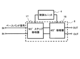
以下、図2を用いて、送信ベースバンド移相器8−1〜8−nに含まれる送信ベースバンド移相器8の構成例について説明する。
Hereinafter, a configuration example of the transmission
送信ベースバンド移相器8は、0°、90°、180°、270°の位相情報付加に寄与する90°ステップ移相器17と、0°、45°の位相付加に寄与する45°移相器18とを備える。
The transmission
そして、90°ステップ移相器17及び45°移相器18は、制御ユニット4からの制御信号に基づいて、制御信号に対応した位相情報をベースバンド信号に付加する。具体的には、90°ステップ移相器17及び45°移相器18は、一方のベースバンド信号を構成する信号と他方のベースバンド信号を構成する信号との入れ替え及び構成信号の極性の反転を行う。図2に示す構成例によれば、ギルバートセルミキサを用いていないので、移相器の消費電力を略ゼロに低減することが可能となる。
Then, the 90 °
次に、図3を用いて、送信ベースバンド移相器8の具体的な構成例について詳しく説明する。
Next, a specific configuration example of the transmission
90°ステップ移相器17は、少なくとも2つのインバータ19、20と、少なくとも16個のスイッチ(スイッチング素子)21−1〜21−8及び22−1〜22−8を備える。
The 90 °
スイッチ21−1〜21−8は、制御信号C1によって制御される。スイッチ22−1〜22−8は、制御信号C2によって制御される。係る制御信号C1、C2は制御ユニット4から供給される。
The switches 21-1 to 21-8 are controlled by a control signal C1. The switches 22-1 to 22-8 are controlled by a control signal C2. The control signals C1 and C2 are supplied from the
差動信号であるI信号は、送信ベースバンド移相器8が有する入力端子IN1と入力端子IN2とに入力される。Q信号も同様に入力端子IN3と入力端子IN4とに入力される。入力されたI信号とQ信号との経路は、制御信号C1と制御信号C2とによって切り替えられる。I信号及びQ信号は、その切り替え状態に応じて、出力端子M1、M2、M3、M4から出力される。このとき、出力端子M1と出力端子M2へ出力されるベースバンド信号は差動ペアである。また、出力端子M3と出力端子M4へ出力されるベースバンド信号も差動ペアとなる。
The I signal, which is a differential signal, is input to the input terminal IN1 and the input terminal IN2 of the transmission
45°移相器18は、少なくとも一つのインバータ23と、少なくとも4個のスイッチング素子24−1〜24−4を備える。スイッチ24−1〜24−4は、制御信号C3によって制御される。制御信号C3は制御信号C1、C2と同様に制御ユニット4から供給される。
The 45 °
具体的には、0°、90°、180°、270°の位相情報を付加する場合には、45°移相器18は、90°ステップ移相器17から出力されたI信号及びQ信号に対して何も操作を加えず、そのまま送信直交変調器へと出力する。
Specifically, when adding phase information of 0 °, 90 °, 180 °, and 270 °, the 45 °
一方、45°、135°、225°、315°の位相情報を付加する場合には、45°移相器18は、入力されるI信号またはQ信号のいずれかのベースバンド信号について、当該ベースバンド信号を構成する信号のうち、一方の極性の信号を2分岐して出力端子OUT1及び出力端子OUT3から出力する。また、45°移相器18は、当該ベースバンド信号を構成する信号のうち、他方の極性の信号を遮断する。一方、45°移相器18は、分岐及び遮断されなかったベースバンド信号を構成する信号を、出力端子OUT2及び出力端子OUT4から出力する。
On the other hand, in the case of adding 45 °, 135 °, 225 °, 315 ° phase information, the 45 °
経路切り替えは、付加すべき位相情報に応じて、表1の位相情報(θ)と出力信号の関係に従い実行される。表1は、本発明の第1の実施形態における位相情報と出力信号との関係を示すテーブルである。90°ステップ移相器17及び45°移相器18によって、表1に例示するように、+I、‐I、+Q、−Q信号の入れ替え及び極性の反転を行う。

送信ベースバンド移相器8の出力端子OUT1から出力されるベースバンド信号は、図8に示す送信ベースバンド移相器101と同様に、送信直交変調器102の、相対位相0°のローカル信号が入力されるミキサ105−1へ入力される。出力端子OUT2から出力されるベースバンド信号は、相対位相180°のローカル信号が入力されるミキサ105−2へ入力される。出力端子OUT3から出力されるベースバンド信号は、相対位相90°のローカル信号が入力されるミキサ105−3へ入力される。出力端子OUT4から出力されるベースバンド信号は、相対位相270°のローカル信号が入力されるミキサ105−4へ入力される。
The baseband signal output from the output terminal OUT1 of the transmission
表1では、制御信号C1、C2、C3の状態を示すために0、1を記述している。かかる記述は、制御信号(C1、C2、C3)の電圧の低(「0」論理レベル)、高(「1」論理レベル)を表しており、入出力の関係が同じであれば、制御信号の状態は表1の限りではない。また表1の関係を満たす回路であれば、インバータ及びスイッチの個数は図3に示す限りでない。 In Table 1, 0 and 1 are described to indicate the states of the control signals C1, C2, and C3. This description represents the low (“0” logic level) and high (“1” logic level) of the voltage of the control signal (C1, C2, C3), and if the input / output relationship is the same, the control signal The state is not limited to that shown in Table 1. If the circuit satisfies the relationship shown in Table 1, the number of inverters and switches is not limited to that shown in FIG.
本実施形態において、制御ユニット4は、例えば表1に示す情報をテーブル(ルックアップテーブル)等として、制御ユニット4の内部または外部から参照可能としてもよい。この場合、制御ユニット4は、必要な位相に応じて、出力すべき制御信号C1、C2、C3の組み合わせを決定する。
In the present embodiment, the
ここで、内部から参照可能とは、例えば、制御ユニット4内に設けられたレジスタに保存されたルックアップテーブルを参照することである。ルックアップテーブルは、電源ONと同時に外部記憶媒体(例えば、HDD(Hard Disk Drive)もしくはフラッシュメモリなど)に記憶されたルックアップテーブルを読み込んだものである。
Here, being able to be referred to from the inside means, for example, referring to a lookup table stored in a register provided in the
外部から参照可能とは、例えば、外部記憶媒体に記憶されたルックアップテーブルを直接参照し、位相制御信号を割り出すことである。 “To be referred to from the outside” refers to, for example, directly referring to a lookup table stored in an external storage medium to determine a phase control signal.
図3に示す構成例によれば、送信ベースバンド移相器8−1〜8−nとしての送信ベースバンド移相器8は、0°、45°、90°、135°、180°、225°、270°、315°の位相情報を付与する。これにより、消費電力を略ゼロにするのに加えて、付加する位相情報の分解能を45°とすることが可能である。
According to the configuration example shown in FIG. 3, the transmission
本実施形態において送信側で説明をしたが、受信側でも同様の動作を行う。 Although the transmission side has been described in the present embodiment, the same operation is performed on the reception side.
実施の形態2
以下、図4を用いて、本発明の第2の実施形態にかかる移相器の構成例について説明する。図4に示す送信ベースバンド移相器8は、図1に示す送信ベースバンド移相器8−1〜8−nを構成する。図4に示すベースバンド移相器8は、送信ベースバンド信号生成ユニット3から出力されるベースバンド信号に対して0°、45°、90°、135°、180°、225°、270°、315°なる位相情報を付与する。
Hereinafter, the configuration example of the phase shifter according to the second embodiment of the present invention will be described with reference to FIG. The transmission
具体的に、本実施形態において、ベースバンド移相器8は、90°ステップ位相変化に寄与する90°ステップ移相器17と、45°位相変化に寄与する45°移相器25から構成される。90°ステップ移相器17は、実施の形態1と同一であるため説明は省略する。
Specifically, in the present embodiment, the
45°移相器25は、制御信号を反転するインバータ26とベースバンド信号の極性を反転するインバータ27と、少なくとも4個のスイッチング素子28−1〜28−4を備える。スイッチ28−1〜28−4は、制御信号C3によって制御される。係る制御信号C3は制御信号C1、C2と同様に制御ユニット4から供給される。
The 45 °
経路切り替えは、実施の形態1と同様に、付加すべき位相情報に応じて表1の位相情報(θ)と出力信号の関係に従い実行される。 Similar to the first embodiment, the path switching is executed according to the relationship between the phase information (θ) and the output signal in Table 1 according to the phase information to be added.
具体的には、45°、135°、225°、315°の位相情報を付加する場合に、45°移相器25は、入力されるI信号またはQ信号のいずれかのベースバンド信号について、当該ベースバンド信号を構成する信号のうち、一方の極性の信号を出力端子OUT1から出力する。また、45°移相器25は、当該ベースバンド信号を構成する信号のうち、他方の極性の信号をインバータ27によって極性を反転して、出力端子OUT3から出力する。一方、45°移相器25は、分岐及び遮断をされなかったベースバンド信号を構成する信号を、出力端子OUT2及び出力端子OUT4から出力する。これにより、ベースバンド信号を構成する信号を分岐することなく表1に示した位相情報と出力信号との関係を実現できる。
Specifically, when adding 45 °, 135 °, 225 °, and 315 ° phase information, the 45 °
送信ベースバンド移相器8の出力端子OUT1、OUT2、OUT3、OUT4から出力されるベースバンド信号は、実施の形態1と同様に直交変調器へ入力される。
Baseband signals output from the output terminals OUT1, OUT2, OUT3, and OUT4 of the transmission
本実施形態において送信側で説明したが、受信側でも同様の動作を行う。 Although the transmission side has been described in the present embodiment, the same operation is performed on the reception side.
実施の形態3
以下、図5を用いて、本発明の第3の実施形態にかかる移相器の構成について説明する。図5に示す送信ベースバンド移相器8は、図1に示す送信ベースバンド移相器8−1〜8−nを構成する。図5に示す送信ベースバンド移相器8は、送信ベースバンド信号生成ユニット3から出力されるベースバンド信号に対して0°、45°、90°、135°、180°、225°、270°、315°なる位相情報を付与する。
Hereinafter, the configuration of the phase shifter according to the third embodiment of the present invention will be described with reference to FIG. The transmission
具体的に、本実施形態において、ベースバンド移相器8は、90°ステップ位相変化に寄与する90°ステップ移相器17と、45°位相変化に寄与する45°移相器29から構成される。90°ステップ移相器17は、実施の形態1と同一であるため説明は省略する。
Specifically, in the present embodiment, the
45°移相器29は、少なくとも一つのインバータ30と、8個のスイッチング素子31−1〜31−8とを備える。スイッチ31−1〜31−8は、制御信号C3によって制御される。係る制御信号C3は制御信号C1、C2と同様に制御ユニット4から供給される。
The 45 °
経路切り替えは、実施の形態1と同様に、付加すべき位相情報に応じて表1の位相情報(θ)と出力信号の関係に従い実行される。 Similar to the first embodiment, the path switching is executed according to the relationship between the phase information (θ) and the output signal in Table 1 according to the phase information to be added.
ここで、スイッチ31−1、31−4、31−5、31−6は図3に示したスイッチ24−1〜24−4と同じ位置に配されており、45°の位相変化に寄与する。残りのスイッチ31−2、31−3、31−7、31−8を備えることで、45°移相器29での経路切り替えに伴う遅延を補償することが実現できる。なお、スイッチ31は、図5において一番上のスイッチがスイッチ31−1で、一番下がスイッチ31−8とする。
Here, the switches 31-1, 31-4, 31-5, and 31-6 are arranged at the same positions as the switches 24-1 to 24-4 shown in FIG. 3, and contribute to a phase change of 45 °. . By providing the remaining switches 31-2, 31-3, 31-7, and 31-8, it is possible to realize a delay due to path switching in the 45 °
また送信ベースバンド移相器8の出力端子OUT1、OUT2、OUT3、OUT4から出力されるベースバンド信号は、実施の形態1と同様に直交変調器へ入力される。
The baseband signals output from the output terminals OUT1, OUT2, OUT3, and OUT4 of the transmission
本実施形態において送信側で説明したが、受信側でも同様の動作を行う。 Although the transmission side has been described in the present embodiment, the same operation is performed on the reception side.
実施の形態4
以下、図6を用いて、本発明の第4の実施形態にかかる移相器の構成について説明する。図6に示す送信ベースバンド移相器8は、図1に示す送信ベースバンド移相器8−1〜8−nを構成する。図5に示す送信ベースバンド移相器8は、送信ベースバンド信号生成ユニット3から出力されるベースバンド信号に対して0°、45°、90°、135°、180°、225°、270°、315°なる位相情報を付与する。
Hereinafter, the configuration of the phase shifter according to the fourth embodiment of the present invention will be described with reference to FIG. The transmission
具体的に、本実施形態において、ベースバンド移相器8は、90°ステップ位相変化に寄与する90°ステップ移相器17と、45°位相変化に寄与する45°移相器29から構成される。45°移相器29の出力には、利得可変増幅器32−1〜32−4が接続されている。90°ステップ移相器17及び45°移相器29は、第3の実施形態と同一であるため説明は省略する。
Specifically, in the present embodiment, the
利得可変増幅器32−1〜32−4は、45°移相器29から出力されるベースバンド信号の振幅を制御ユニット4からの制御信号C4により変更する。この際、利得可変増幅器32−1〜32−4の各々の利得は変更可能である。そのため、90°ステップ移相器17と45°移相器29で生じた振幅誤差が補正可能である。
The variable gain amplifiers 32-1 to 32-4 change the amplitude of the baseband signal output from the 45 °
また送信ベースバンド移相器8の出力端子OUT1、OUT2、OUT3、OUT4から出力されるベースバンド信号は、第1の実施形態と同様に直交変調器へ入力される。
The baseband signals output from the output terminals OUT1, OUT2, OUT3, and OUT4 of the transmission
本実施形態において送信側で説明したが、受信側でも同様の動作を行う。 Although the transmission side has been described in the present embodiment, the same operation is performed on the reception side.
実施の形態5
以下、図7を用いて、本発明の第5の実施形態にかかる位相制御方法について説明する。はじめに、制御ユニット4は、ベースバンド信号に付加する位相情報について、付加する位相情報が0°、90°、180°、270°であるか、または、45°、135°、225°、315°であるかを判断する(S71)。Embodiment 5
Hereinafter, the phase control method according to the fifth embodiment of the present invention will be described with reference to FIG. First, with respect to the phase information added to the baseband signal, the
次に、前記位相情報に基づいて、送信ベースバンド移相器8は、表1に例示する位相情報(θ)と出力信号の関係に従い、ベースバンド信号を構成する+I、‐I、+Q、−Q信号の入れ替え及び極性の反転を行う(S72、S73)。
Next, based on the phase information, the transmission
そして、前記位相情報が、0°、90°、180°、270°の場合には、送信直交変調器9は、I信号またはQ信号を構成する信号の差動ペアと、相対位相が0°と180°であるローカル信号とをそれぞれ混合する。また、他方のベースバンド信号を構成する信号の差動ペアと、相対位相が90°と270°であるローカル信号とをそれぞれ混合する(S74)。
When the phase information is 0 °, 90 °, 180 °, or 270 °, the
一方、前記位相情報が、45°、135°、225°、315°の場合には、送信直交変調器9は、I信号またはQ信号を構成する信号の差動ペアと、相対位相が0°と90°であるローカル信号とをそれぞれ混合する。また、他方のベースバンド信号を構成する信号の差動ペアと、相対位相が180°と270°であるローカル信号とをそれぞれ混合する(S75)。これによって、位相分解能が45°である位相制御が可能となる。
On the other hand, when the phase information is 45 °, 135 °, 225 °, 315 °, the
なお、本発明は上述した実施の形態のみに限定されるものではなく、既に述べた本発明の要旨を逸脱しない範囲において種々の変更が可能であることは勿論である。 It should be noted that the present invention is not limited to the above-described embodiment, and various modifications can be made without departing from the gist of the present invention already described.
この出願は、2009年5月14日に出願された日本出願特願2009−117221を基礎とする優先権を主張し、その開示の全てをここに取り込む。 This application claims the priority on the basis of Japanese application Japanese Patent Application No. 2009-117221 for which it applied on May 14, 2009, and takes in those the indications of all here.
1 送信機
2 受信機
3 送信ベースバンド信号生成ユニット
4 制御ユニット
5 受信ベースバンド信号処理ユニット
6 ローカル発振器
7−1、7−2 分配器
8−1〜8−n 送信ベースバンド移相器
9−1〜9−n 送信直交変調器
10−1〜10−n 送信増幅器
11−1〜11−n 送信アンテナ
12−1、12−2 合成器
13−1〜13−m 受信ベースバンド移相器
14−1〜14−m 受信直交復調器
15−1〜15−m 受信増幅器
16−1〜16−m 受信アンテナ
17 90°ステップ移相器
18 45°移相器
19 インバータ
20 インバータ
21−1〜21−8 スイッチ(スイッチ素子)
22−1〜22−8 スイッチ(スイッチ素子)
23 インバータ
24−1〜24−4 スイッチ(スイッチ素子)
25 45°移相器
26 インバータ
27 インバータ
28−1〜28−4 スイッチ(スイッチ素子)
29 45°移相器
30 インバータ
31−1〜31−8 スイッチ(スイッチ素子)
32−1〜32−4 利得可変増幅器
101 送信ベースバンド移相器
102 送信直交変調器
103 90°ステップ移相器
104 信号混合器
105−1〜105−4 ミキサ
106 合成器
107 分配器DESCRIPTION OF
22-1 to 22-8 Switch (switch element)
23 Inverters 24-1 to 24-4 Switches (switch elements)
25 45 °
29 45 °
32-1 to 32-4
Claims (13)
第一の制御信号に応じて、前記ベースバンド信号に、0°、90°、180°、270°のうち、いずれかの位相を付加することに寄与する90°ステップ移相器と、
第二の制御信号に応じて、前記90°ステップ位相器から出力されたベースバンド信号に、0°、45°のうち、いずれかの位相を付加することに寄与する45°移相器と、を備え、
一方のベースバンド信号を構成する信号と他方のベースバンド信号を構成する信号との入れ替えと、前記一方のベースバンド信号を構成する信号及び前記他方のベースバンド信号を構成する信号の極性の反転と、を行う移相器。 In order to control the phase of the output signal of the quadrature modulator, a phase shifter that adds phase information to two baseband signals and outputs the phase information to the quadrature modulator,
A 90 ° step phase shifter that contributes to adding any phase of 0 °, 90 °, 180 °, and 270 ° to the baseband signal in response to a first control signal;
A 45 ° phase shifter that contributes to adding one of 0 ° and 45 ° to the baseband signal output from the 90 ° step phaser according to a second control signal; With
And replacement of the signal constituting the signal and the other of the baseband signal constituting one of the baseband signal, and the polarity inversion signal constituting a baseband signal of the one and the signals constituting the other of the baseband signal , Do the phase shifter.
前記位相情報が、0°、90°、180°、270°の場合には、
前記移相器は、前記45°位相器から出力された一方のベースバンド信号を構成する信号を、前記直交変調器を構成するミキサのうち、相対位相が0°と180°であるローカル信号が入力されるミキサへそれぞれ入力し、前記45°位相器から出力された他方のベースバンド信号を構成する信号を、相対位相が90°と270°であるローカル信号が入力されるミキサへそれぞれ入力し、
前記位相情報が、45°、135°、225°、315°の場合には、
前記移相器は、前記45°位相器から出力された一方のベースバンド信号を構成する信号を、前記直交変調器を構成するミキサのうち、相対位相が0°と90°であるローカル信号が入力されるミキサへそれぞれ入力し、前記45°位相器から出力された他方のベースバンド信号を構成する信号を、相対位相が180°と270°であるローカル信号が入力されるミキサへそれぞれ入力する請求項1記載の移相器。 The phase information is one of 0 °, 45 °, 90 °, 135 °, 180 °, 225 °, 270 °, and 315 °,
When the phase information is 0 °, 90 °, 180 °, 270 °,
The phase shifter converts a signal constituting one baseband signal output from the 45 ° phase shifter into a local signal having a relative phase of 0 ° and 180 ° among the mixers constituting the quadrature modulator. The other baseband signal output from the 45 ° phase shifter is input to the input mixer and the local signal having a relative phase of 90 ° and 270 ° is input to the mixer. ,
When the phase information is 45 °, 135 °, 225 °, 315 °,
The phase shifter outputs a signal constituting one baseband signal output from the 45 ° phase shifter to a local signal having a relative phase of 0 ° and 90 ° among the mixers constituting the quadrature modulator. The signals constituting the other baseband signal output from the 45 ° phase shifter are respectively input to the mixers to which the local signals having relative phases of 180 ° and 270 ° are input. The phase shifter according to claim 1.
前記45°位相器は、前記90°ステップ位相器から出力されたベースバンド信号を構成する信号のうち、一方の極性の信号を2分岐して、前記0°と90°のローカル信号が入力されるミキサへ前記2分岐した信号を入力し、他方の極性の信号を遮断する請求項1または2記載の移相器。 When the phase information is 45 °, 135 °, 225 °, or 315 °, the signals constituting the one baseband signal output from the 45 ° phase shifter have relative phases of 0 ° and 90 °. A phase shifter that inputs to a mixer to which a local signal is input,
The 45 ° phase shifter divides the signal of one polarity out of the signals constituting the baseband signal output from the 90 ° step phase shifter, and the local signals of 0 ° and 90 ° are inputted. The phase shifter according to claim 1 or 2, wherein the two-branched signal is input to a mixer and the other polarity signal is cut off.
前記45°位相器は、前記90°ステップ位相器から出力されたベースバンド信号を構成する信号のうち、一方の極性の信号を相対位相0°のローカル信号が入力されるミキサへ入力し、他方の極性の信号は、極性を反転させ90°のローカル信号が入力されるミキサへ入力する請求項1または2記載の移相器。 When the phase information is 45 °, 135 °, 225 °, 315 °, the signals constituting one of the baseband signals output from the 45 ° phase shifter have a relative phase of 0 ° and 90 °. A phase shifter that inputs each to a mixer to which a local signal is input,
The 45 ° phase shifter inputs a signal of one polarity among the signals constituting the baseband signal output from the 90 ° step phase shifter to a mixer to which a local signal having a relative phase of 0 ° is input, and the other The phase shifter according to claim 1 or 2, wherein the polarity signal is input to a mixer that reverses the polarity and receives a 90 ° local signal.
前記ローカル信号と混合される二つのベースバンド信号に、0°、45°、90°、135°、180°、225°、270°、315°のうち、いずれの位相情報を付加するかに応じて、0°、90°、180°、270°のうち、いずれかの第1位相情報を付加し、当該第1位相情報が付加されたベースバンド信号に、0°、45°のうち、いずれかの第2位相情報を付加することにより、一方のベースバンド信号を構成する信号と他方のベースバンド信号を構成する信号との入れ替えと、前記一方のベースバンド信号を構成する信号及び前記他方のベースバンド信号を構成する信号の極性の反転と、を行い、
直交変調を実行し、
前記直交変調の実行は、
前記位相情報が、0°、90°、180°、270°の場合には、
前記第2位相情報が付加された一方のベースバンド信号を構成する信号と、相対位相が0°と180°であるローカル信号とをそれぞれ混合し、
前記第2位相情報が付加された他方のベースバンド信号を構成する信号と、相対位相が90°と270°であるローカル信号とをそれぞれ混合し、
前記位相情報が、45°、135°、225°、315°の場合には、
前記第2位相情報が付加された一方のベースバンド信号を構成する信号と、相対位相が0°と90°であるローカル信号とをそれぞれ混合し、
前記第2位相情報が付加された他方のベースバンド信号を構成する信号と、相対位相が180°と270°であるローカル信号とをそれぞれ混合する位相制御方法。 In order to control the phase of the output signal of the quadrature modulator, a phase control method for adding phase information to two baseband signals and mixing it with a local signal,
Depending on which phase information of 0 °, 45 °, 90 °, 135 °, 180 °, 225 °, 270 °, 315 ° is added to the two baseband signals mixed with the local signal Then , any one of 0 °, 90 °, 180 °, and 270 ° is added, and any of 0 ° and 45 ° is added to the baseband signal to which the first phase information is added. By adding the second phase information, the signal constituting one baseband signal and the signal constituting the other baseband signal are interchanged, and the signal constituting the one baseband signal and the other carried out, reversing the polarity of the signal constituting the base band signal,
Perform quadrature modulation,
The execution of the quadrature modulation is
When the phase information is 0 °, 90 °, 180 °, 270 °,
A signal constituting one baseband signal to which the second phase information is added and a local signal having a relative phase of 0 ° and 180 °, respectively,
A signal constituting the other baseband signal to which the second phase information is added and a local signal having relative phases of 90 ° and 270 °, respectively,
When the phase information is 45 °, 135 °, 225 °, 315 °,
A signal constituting one baseband signal to which the second phase information is added and a local signal having a relative phase of 0 ° and 90 °, respectively,
A phase control method for mixing a signal constituting the other baseband signal to which the second phase information is added and a local signal having relative phases of 180 ° and 270 °, respectively.
前記第1位相情報が付加された一方のベースバンド信号を構成する信号のうち、一方の極性の信号を2信号に分配し、
前記2信号を、相対位相が0°と90°であるローカル信号と混合し、他方の極性の信号を遮る請求項11記載の位相制御方法。 When the phase information is 45 °, 135 °, 225 °, 315 °,
Distributing a signal of one polarity among two signals constituting one baseband signal to which the first phase information is added , to two signals,
The phase control method according to claim 11, wherein the two signals are mixed with a local signal having relative phases of 0 ° and 90 °, and the signal of the other polarity is blocked.
前記第1位相情報が付加された一方のベースバンド信号を構成する信号のうち、一方の極性の信号を、相対位相0°のローカル信号と混合し、
他方の極性の信号は、極性を反転させ相対位相90°のローカル信号と混合する請求項11記載の位相制御方法。 When the phase information is 45 °, 135 °, 225 °, 315 °,
Of the signals constituting one baseband signal to which the first phase information is added , one polarity signal is mixed with a local signal having a relative phase of 0 °,
The phase control method according to claim 11, wherein the signal of the other polarity is inverted and mixed with a local signal having a relative phase of 90 °.
Priority Applications (1)
| Application Number | Priority Date | Filing Date | Title |
|---|---|---|---|
| JP2011513220A JP5360204B2 (en) | 2009-05-14 | 2010-03-26 | Phase shifter, wireless communication apparatus, and phase control method |
Applications Claiming Priority (4)
| Application Number | Priority Date | Filing Date | Title |
|---|---|---|---|
| JP2009117221 | 2009-05-14 | ||
| JP2009117221 | 2009-05-14 | ||
| JP2011513220A JP5360204B2 (en) | 2009-05-14 | 2010-03-26 | Phase shifter, wireless communication apparatus, and phase control method |
| PCT/JP2010/002221 WO2010131408A1 (en) | 2009-05-14 | 2010-03-26 | Phase shifter, wireless communication apparatus, and phase shift control method |
Publications (2)
| Publication Number | Publication Date |
|---|---|
| JPWO2010131408A1 JPWO2010131408A1 (en) | 2012-11-01 |
| JP5360204B2 true JP5360204B2 (en) | 2013-12-04 |
Family
ID=43084794
Family Applications (1)
| Application Number | Title | Priority Date | Filing Date |
|---|---|---|---|
| JP2011513220A Active JP5360204B2 (en) | 2009-05-14 | 2010-03-26 | Phase shifter, wireless communication apparatus, and phase control method |
Country Status (4)
| Country | Link |
|---|---|
| US (1) | US8665989B2 (en) |
| EP (1) | EP2432075B1 (en) |
| JP (1) | JP5360204B2 (en) |
| WO (1) | WO2010131408A1 (en) |
Cited By (1)
| Publication number | Priority date | Publication date | Assignee | Title |
|---|---|---|---|---|
| KR101624287B1 (en) | 2015-01-14 | 2016-05-25 | (주)엑스엠더블유 | Efficient digital phase shifter |
Families Citing this family (1)
| Publication number | Priority date | Publication date | Assignee | Title |
|---|---|---|---|---|
| US9584231B2 (en) * | 2014-10-30 | 2017-02-28 | Samsung Electronics Co., Ltd. | Integrated two dimensional active antenna array communication system |
Citations (4)
| Publication number | Priority date | Publication date | Assignee | Title |
|---|---|---|---|---|
| JPH11243351A (en) * | 1998-02-25 | 1999-09-07 | Icom Inc | Frequency synthesizer |
| WO2002017485A1 (en) * | 2000-08-21 | 2002-02-28 | Mitsubishi Denki Kabushiki Kaisha | π/2 PHASE SHIFTER |
| JP2005286569A (en) * | 2004-03-29 | 2005-10-13 | Mitsubishi Electric Corp | Phase shifter, local signal generating circuit, and modem |
| WO2006126462A1 (en) * | 2005-05-24 | 2006-11-30 | Matsushita Electric Industrial Co., Ltd. | Broadcasting system, radio receiver, electronic device, and radio broadcasting modulation/demodulation method |
Family Cites Families (15)
| Publication number | Priority date | Publication date | Assignee | Title |
|---|---|---|---|---|
| US5535244A (en) * | 1993-06-07 | 1996-07-09 | Matsushita Electric Industrial Co., Ltd. | Digital modulating/demodulating apparatus and a digital demodulating apparatus |
| US5748680A (en) * | 1994-12-16 | 1998-05-05 | Lucent Technologies Inc. | Coarse frequency burst detector for a wireline communications system |
| JP3252639B2 (en) * | 1995-03-03 | 2002-02-04 | 三菱電機株式会社 | Detector, receiving device, and transmitting device |
| JP3252820B2 (en) * | 1999-02-24 | 2002-02-04 | 日本電気株式会社 | Demodulation and modulation circuit and demodulation and modulation method |
| US6320480B1 (en) | 1999-10-26 | 2001-11-20 | Trw Inc. | Wideband low-loss variable delay line and phase shifter |
| US6748024B2 (en) * | 2001-03-28 | 2004-06-08 | Nokia Corporation | Non-zero complex weighted space-time code for multiple antenna transmission |
| US6983024B2 (en) * | 2003-03-18 | 2006-01-03 | Qualcomm Inc. | Quadra-polar modulator |
| JP2006086857A (en) * | 2004-09-16 | 2006-03-30 | Matsushita Electric Ind Co Ltd | Phase-shifting device |
| CN101160748B (en) * | 2005-03-28 | 2012-07-04 | 松下电器产业株式会社 | Transmission method and transmission system |
| US7545856B2 (en) * | 2005-09-08 | 2009-06-09 | Broadcom Corporation | Current mode phase shifter, mixer and amplifier |
| US20070160168A1 (en) * | 2006-01-11 | 2007-07-12 | Beukema Troy J | Apparatus and method for signal phase control in an integrated radio circuit |
| JP4172805B2 (en) * | 2006-07-12 | 2008-10-29 | 株式会社東芝 | Communication device, orthogonal error compensation setting value calculation method, and orthogonal error compensation program |
| US7904045B2 (en) * | 2006-08-04 | 2011-03-08 | Axiom Microdevices, Inc. | Phase detector comprising a switch configured to select a phase offset closest to a phase of an amplifier |
| EP1977743B1 (en) | 2007-03-20 | 2009-09-02 | Johnson & Johnson Consumer France SAS | Compositions containing retinoid and beta-aminoisobutyric acid derivates |
| JP2009117221A (en) | 2007-11-08 | 2009-05-28 | Toyota Motor Corp | Fuel cell having stack structure |
-
2010
- 2010-03-26 WO PCT/JP2010/002221 patent/WO2010131408A1/en active Application Filing
- 2010-03-26 US US13/264,046 patent/US8665989B2/en active Active
- 2010-03-26 JP JP2011513220A patent/JP5360204B2/en active Active
- 2010-03-26 EP EP10774668.7A patent/EP2432075B1/en active Active
Patent Citations (4)
| Publication number | Priority date | Publication date | Assignee | Title |
|---|---|---|---|---|
| JPH11243351A (en) * | 1998-02-25 | 1999-09-07 | Icom Inc | Frequency synthesizer |
| WO2002017485A1 (en) * | 2000-08-21 | 2002-02-28 | Mitsubishi Denki Kabushiki Kaisha | π/2 PHASE SHIFTER |
| JP2005286569A (en) * | 2004-03-29 | 2005-10-13 | Mitsubishi Electric Corp | Phase shifter, local signal generating circuit, and modem |
| WO2006126462A1 (en) * | 2005-05-24 | 2006-11-30 | Matsushita Electric Industrial Co., Ltd. | Broadcasting system, radio receiver, electronic device, and radio broadcasting modulation/demodulation method |
Cited By (1)
| Publication number | Priority date | Publication date | Assignee | Title |
|---|---|---|---|---|
| KR101624287B1 (en) | 2015-01-14 | 2016-05-25 | (주)엑스엠더블유 | Efficient digital phase shifter |
Also Published As
| Publication number | Publication date |
|---|---|
| JPWO2010131408A1 (en) | 2012-11-01 |
| US20120039370A1 (en) | 2012-02-16 |
| EP2432075A1 (en) | 2012-03-21 |
| US8665989B2 (en) | 2014-03-04 |
| EP2432075A4 (en) | 2017-04-26 |
| EP2432075B1 (en) | 2018-11-14 |
| WO2010131408A1 (en) | 2010-11-18 |
Similar Documents
| Publication | Publication Date | Title |
|---|---|---|
| US8891681B2 (en) | Transmitters and methods | |
| US8611959B2 (en) | Low cost, active antenna arrays | |
| KR102286423B1 (en) | Reconfiguration of single-band transmit and receive paths into multi-band transmit and receive paths in an integrated circuit | |
| US10122404B2 (en) | Wireless transceiver for transmitting circularly-polarized signals with modulated angular speed | |
| US9294178B2 (en) | Method and apparatus for transceiving for beam forming in wireless communication system | |
| US9287960B2 (en) | Radio communication apparatus, transmitter, and radio communication method | |
| US10700755B2 (en) | Antenna mapping and diversity | |
| US10784636B1 (en) | Asymmetrical quadrature hybrid coupler | |
| JPS5819038A (en) | Radio receiver for frequency transient modulation signal | |
| TW201249121A (en) | Phase-arrayed transceiver and transceiving element of phase-arrayed transceiver | |
| US11228290B2 (en) | Mixer having phase shift function and communications device including the same | |
| CN111066257B (en) | Communication node and method for generating a beamformed signal through backscatter | |
| CN114128167A (en) | Flexible beamforming architecture | |
| WO2009101993A1 (en) | Phase shifter and method for controlling same, and radio communication device with array antenna | |
| JP5360204B2 (en) | Phase shifter, wireless communication apparatus, and phase control method | |
| US6879220B2 (en) | Switchless combining of multi-carrier coherent and incoherent carriers | |
| TWI813371B (en) | Rf receiver and method for receiving rf input signal | |
| EP3272020B1 (en) | A beamforming receiver | |
| US20210376875A1 (en) | Wireless device | |
| EP3847747B1 (en) | Cascaded transmit and receive local oscillator distribution network | |
| US11923878B2 (en) | Wireless signal processing circuit and wireless device | |
| JP2007068089A (en) | Transponder | |
| EP1499010A2 (en) | Frequency translator, and method | |
| JP2021057648A (en) | Phased array antenna device and control method for the same | |
| JP2006238125A (en) | Radio transceiver |
Legal Events
| Date | Code | Title | Description |
|---|---|---|---|
| A131 | Notification of reasons for refusal |
Free format text: JAPANESE INTERMEDIATE CODE: A131 Effective date: 20130507 |
|
| A521 | Written amendment |
Free format text: JAPANESE INTERMEDIATE CODE: A523 Effective date: 20130703 |
|
| TRDD | Decision of grant or rejection written | ||
| A01 | Written decision to grant a patent or to grant a registration (utility model) |
Free format text: JAPANESE INTERMEDIATE CODE: A01 Effective date: 20130806 |
|
| A61 | First payment of annual fees (during grant procedure) |
Free format text: JAPANESE INTERMEDIATE CODE: A61 Effective date: 20130819 |
|
| R150 | Certificate of patent or registration of utility model |
Ref document number: 5360204 Country of ref document: JP Free format text: JAPANESE INTERMEDIATE CODE: R150 Free format text: JAPANESE INTERMEDIATE CODE: R150 |