JP5356786B2 - Information processing system - Google Patents

Information processing system Download PDF

Info

Publication number
JP5356786B2
JP5356786B2 JP2008298810A JP2008298810A JP5356786B2 JP 5356786 B2 JP5356786 B2 JP 5356786B2 JP 2008298810 A JP2008298810 A JP 2008298810A JP 2008298810 A JP2008298810 A JP 2008298810A JP 5356786 B2 JP5356786 B2 JP 5356786B2
Authority
JP
Japan
Prior art keywords
operation device
light emitting
emitting unit
light
light emission
Prior art date
Legal status (The legal status is an assumption and is not a legal conclusion. Google has not performed a legal analysis and makes no representation as to the accuracy of the status listed.)
Active
Application number
JP2008298810A
Other languages
Japanese (ja)
Other versions
JP2010123087A (en
JP2010123087A5 (en
Inventor
豊 須見
良雄 宮崎
善数 大貫
幸治 濱田
和義 榎本
Current Assignee (The listed assignees may be inaccurate. Google has not performed a legal analysis and makes no representation or warranty as to the accuracy of the list.)
Sony Interactive Entertainment Inc
Original Assignee
Sony Interactive Entertainment Inc
Sony Computer Entertainment Inc
Priority date (The priority date is an assumption and is not a legal conclusion. Google has not performed a legal analysis and makes no representation as to the accuracy of the date listed.)
Filing date
Publication date
Priority to JP2008298810A priority Critical patent/JP5356786B2/en
Application filed by Sony Interactive Entertainment Inc, Sony Computer Entertainment Inc filed Critical Sony Interactive Entertainment Inc
Priority to PCT/JP2009/067174 priority patent/WO2010055737A1/en
Priority to CN2009801544397A priority patent/CN102282528A/en
Priority to US13/128,926 priority patent/US8747224B2/en
Priority to EP09825990.6A priority patent/EP2354896B1/en
Publication of JP2010123087A publication Critical patent/JP2010123087A/en
Publication of JP2010123087A5 publication Critical patent/JP2010123087A5/ja
Application granted granted Critical
Publication of JP5356786B2 publication Critical patent/JP5356786B2/en
Priority to US14/263,303 priority patent/US9028326B2/en
Active legal-status Critical Current
Anticipated expiration legal-status Critical

Links

Images

Abstract

<P>PROBLEM TO BE SOLVED: To provide an information processing system allowing a user to easily determine the state of an operating device. <P>SOLUTION: The information processing system includes an operating device 20 having a light emitting section and an information processing device 10. The information processing device 10 detects light emitted from the light emitting section, and specifies the position of the operating device according to the position of the detected light. The operating device 20 changes the light emitting state of the light emitting section according to the state of the operating device. <P>COPYRIGHT: (C)2010,JPO&amp;INPIT

Description

本発明は、発光部を備えた操作デバイスと、当該発光部から発せられる光を用いて操作デバイスの位置を特定する情報処理装置と、を含んだ情報処理システム、当該情報処理システムを構成する操作デバイス及び情報処理装置、情報処理装置の制御方法、プログラム、並びに情報記憶媒体に関する。   The present invention relates to an information processing system including an operation device including a light emitting unit, and an information processing device that identifies the position of the operation device using light emitted from the light emitting unit, and an operation constituting the information processing system The present invention relates to a device, an information processing apparatus, a control method for the information processing apparatus, a program, and an information storage medium.

情報処理装置を操作するための各種の操作デバイスの中には、発光部を備えたものがある。情報処理装置は、この発光部から発せられる光を検出することによって、操作デバイスの位置を特定する。このような操作デバイスによれば、ユーザは保持している操作デバイス自体を動かすことによって、情報処理装置に対する各種の操作入力を行うことができる(例えば特許文献1参照)。
米国特許出願公開第2007/0117625号明細書
Some types of operation devices for operating the information processing apparatus include a light emitting unit. The information processing apparatus identifies the position of the operation device by detecting light emitted from the light emitting unit. According to such an operation device, the user can perform various operation inputs to the information processing apparatus by moving the operation device held by the user (see, for example, Patent Document 1).
US Patent Application Publication No. 2007/0117625

上述した例において、操作デバイスのユーザは、例えば操作デバイスに内蔵された充電池の充電状態など、各種の機器状態を必要に応じて確認したいという要望がある。しかしながら、このような機器状態を表示するインジケータ等を操作デバイスに設けることとすると、インジケータ等の表示が、発光部からの光によって操作デバイスの位置を検出する際に誤検出の原因となるおそれがある。   In the above-described example, there is a request that the user of the operation device wants to check various device states as necessary, such as a charge state of a rechargeable battery built in the operation device. However, if the operation device is provided with an indicator or the like for displaying such a device status, the display of the indicator or the like may cause a false detection when the position of the operation device is detected by light from the light emitting unit. is there.

本発明は上記実情を考慮してなされたものであって、その目的の一つは、操作デバイスの機器状態をユーザが容易に把握できる情報処理システム、操作デバイス、情報処理装置、その制御方法、プログラム、及び情報記憶媒体を提供することにある。   The present invention has been made in consideration of the above circumstances, and one of its purposes is an information processing system, an operation device, an information processing apparatus, a control method thereof, and an information processing system in which a user can easily grasp the device state of the operation device. It is to provide a program and an information storage medium.

本発明に係る情報処理システムは、発光部を備えた操作デバイスと、情報処理装置と、を含む情報処理システムであって、前記情報処理装置は、前記発光部から発せられる光を検出する検出手段と、前記検出された光の位置に応じて、前記操作デバイスの位置を特定する位置特定手段と、を備え、前記操作デバイスは、当該操作デバイスの機器状態に応じて、前記発光部の発光態様を変化させることを特徴とする。   An information processing system according to the present invention is an information processing system including an operation device including a light emitting unit, and an information processing apparatus, wherein the information processing apparatus detects light emitted from the light emitting unit. And position specifying means for specifying the position of the operation device according to the detected position of the light, the operation device according to the device state of the operation device It is characterized by changing.

上記情報処理システムにおいて、前記操作デバイスは、当該操作デバイスに内蔵された充電池の充電状態に応じて、前記発光部の発光態様を変化させることとしてもよい。   The said information processing system WHEREIN: The said operation device is good also as changing the light emission mode of the said light emission part according to the charge condition of the rechargeable battery incorporated in the said operation device.

さらに、前記操作デバイスは、前記充電池の充電残量が所定の閾値を下回った場合に、前記発光部の発光色を変化させることとしてもよい。   Furthermore, the operation device may change a light emission color of the light emitting unit when a remaining charge amount of the rechargeable battery falls below a predetermined threshold.

また、上記情報処理システムにおいて、前記操作デバイスは、ユーザの指示に応じて、前記充電池の充電状態に応じた態様で前記発光部を発光させることとしてもよい。   In the information processing system, the operation device may cause the light emitting unit to emit light in a mode according to a state of charge of the rechargeable battery in accordance with a user instruction.

また、本発明に係る操作デバイスは、発光部を備える操作デバイスであって、前記発光部から発せられる光が情報処理装置による当該操作デバイスの位置の特定に用いられ、当該操作デバイスの機器状態に応じて、前記発光部の発光態様を変化させることを特徴とする。   The operating device according to the present invention is an operating device including a light emitting unit, and light emitted from the light emitting unit is used for specifying a position of the operating device by an information processing apparatus, and the device state of the operating device is set. Accordingly, the light emission mode of the light emitting unit is changed.

また、本発明に係る情報処理装置は、発光部を備えた操作デバイスと通信接続される情報処理装置であって、前記発光部から発せられる光を検出する検出手段と、前記検出された光の位置に応じて、前記操作デバイスの位置を特定する位置特定手段と、前記操作デバイスの機器状態を取得する手段と、前記取得した操作デバイスの機器状態に応じて、前記発光部の発光態様を変化させる発光制御手段と、を含むことを特徴とする。   Further, an information processing apparatus according to the present invention is an information processing apparatus that is connected to an operation device including a light emitting unit, and includes a detection unit that detects light emitted from the light emitting unit, and a detector that detects the detected light. According to the position, the position specifying means for specifying the position of the operation device, the means for acquiring the device state of the operation device, and the light emission mode of the light emitting unit is changed according to the acquired device state of the operation device. Light emission control means.

また、本発明に係る情報処理装置の制御方法は、発光部を備えた操作デバイスと通信接続される情報処理装置の制御方法であって、前記発光部から発せられる光を検出するステップと、前記検出された光の位置に応じて、前記操作デバイスの位置を特定するステップと、前記操作デバイスの機器状態を取得するステップと、前記取得した操作デバイスの機器状態に応じて、前記発光部の発光態様を変化させるステップと、を含むことを特徴とする。   Further, the control method of the information processing apparatus according to the present invention is a control method of the information processing apparatus that is communicatively connected to an operation device including a light emitting unit, the step of detecting light emitted from the light emitting unit, The step of identifying the position of the operation device according to the detected light position, the step of acquiring the device state of the operation device, and the light emission of the light emitting unit according to the acquired device state of the operation device And a step of changing the aspect.

また、本発明に係るプログラムは、発光部を備えた操作デバイスと通信接続され、前記発光部から発せられる光を検出する検出手段を備える情報処理装置を、前記検出された光の位置に応じて、前記操作デバイスの位置を特定する位置特定手段、前記操作デバイスの機器状態を取得する手段、及び前記取得した操作デバイスの機器状態に応じて、前記発光部の発光態様を変化させる発光制御手段、として機能させるためのプログラムである。このプログラムは、コンピュータ読み取り可能な情報記憶媒体に記憶されてよい。   According to another aspect of the present invention, there is provided a program according to the present invention, wherein an information processing apparatus that is connected to an operation device including a light emitting unit and includes a detecting unit that detects light emitted from the light emitting unit is provided according to the detected light position. Position specifying means for specifying the position of the operation device, means for acquiring the device state of the operation device, and light emission control means for changing the light emission mode of the light emitting unit according to the acquired device state of the operation device, It is a program to make it function as. This program may be stored in a computer-readable information storage medium.

以下、本発明の実施の形態について、図面に基づき詳細に説明する。   Hereinafter, embodiments of the present invention will be described in detail with reference to the drawings.

図1は、本発明の一実施形態に係る情報処理システム1の概要図である。同図に示されるように、情報処理システム1は、撮像部14を備え、表示装置15と接続される情報処理装置10と、それぞれ発光部を備える複数の操作デバイス20と、を含んで構成される。また、各操作デバイス20は、無線通信インタフェースを介して情報処理装置10と通信接続可能になっている。情報処理システム1のユーザは、操作デバイス20を保持して、操作デバイス20に設けられたボタン等を手で操作する。これに応じて、ユーザの操作内容が無線通信インタフェースを介して情報処理装置10に対して送信される。また、情報処理装置10は、各操作デバイス20の発光部から発せられる光を撮像部14によって撮像し、当該撮像された画像を用いて各操作デバイス20の実空間上の位置を特定する。これにより、各ユーザは操作デバイス20に設けられたボタン等を操作するだけでなく、操作デバイス20自体を動かすことによって、情報処理装置10に対する操作入力を行うことができる。   FIG. 1 is a schematic diagram of an information processing system 1 according to an embodiment of the present invention. As illustrated in FIG. 1, the information processing system 1 includes an imaging unit 14 and includes an information processing device 10 connected to a display device 15 and a plurality of operation devices 20 each including a light emitting unit. The Each operation device 20 can be connected to the information processing apparatus 10 via a wireless communication interface. A user of the information processing system 1 holds the operation device 20 and operates a button or the like provided on the operation device 20 by hand. In response to this, the user's operation content is transmitted to the information processing apparatus 10 via the wireless communication interface. Further, the information processing apparatus 10 captures the light emitted from the light emitting unit of each operation device 20 by the imaging unit 14 and specifies the position of each operation device 20 in the real space using the captured image. Thereby, each user can perform operation input to the information processing apparatus 10 not only by operating a button or the like provided on the operation device 20 but also by moving the operation device 20 itself.

以下、本実施形態における情報処理装置10及び操作デバイス20のハードウェア構成について説明する。   Hereinafter, the hardware configuration of the information processing apparatus 10 and the operation device 20 in the present embodiment will be described.

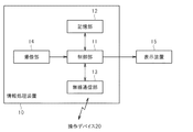
情報処理装置10は、例えば家庭用ゲーム機やパーソナルコンピュータ等であって、図2に示されるように、制御部11と、記憶部12と、無線通信部13と、撮像部14と、を含んで構成される。また、情報処理装置10は、表示装置15と接続されている。   The information processing apparatus 10 is, for example, a home game machine or a personal computer, and includes a control unit 11, a storage unit 12, a wireless communication unit 13, and an imaging unit 14, as shown in FIG. Consists of. The information processing device 10 is connected to the display device 15.

制御部11は、例えばマイクロプロセッサ等であって、記憶部12に記憶されるプログラムに従って、各種の情報処理を実行する。本実施形態において制御部11が実行する処理の具体例については、後述する。   The control unit 11 is a microprocessor, for example, and executes various types of information processing according to programs stored in the storage unit 12. A specific example of processing executed by the control unit 11 in the present embodiment will be described later.

記憶部12は、例えばRAMやROM等のメモリ素子を含んで構成され、制御部11が実行するプログラムや、各種のデータを記憶する。また、制御部11のワークメモリとしても動作する。   The storage unit 12 includes a memory element such as a RAM or a ROM, and stores programs executed by the control unit 11 and various data. It also operates as a work memory for the control unit 11.

無線通信部13は、無線通信インタフェースであって、伝送線を介さずに無線通信によって操作デバイス20との間で情報の送受信を行う。無線通信部13は、例えばbluetooth(登録商標)規格に基づく無線通信インタフェースであってよい。本実施形態において、無線通信部13は、複数の操作デバイス20との間でデータの送受信を実行可能になっている。すなわち、無線通信部13は、各操作デバイス20との間で通信接続を確立し、時分割多重通信を行ったり、互いに異なる周波数帯域で通信を行ったりするなどの方法で、各操作デバイス20との間で通信を行う。なお、同時期に複数の操作デバイス20が情報処理装置10に接続される場合、情報処理装置10は、各操作デバイス20に対して、当該操作デバイス20を識別するための論理番号を割り当てる。情報処理装置10は、この論理番号によって各操作デバイス20を識別して、データ交換を行う。   The wireless communication unit 13 is a wireless communication interface, and transmits and receives information to and from the operation device 20 by wireless communication without using a transmission line. The wireless communication unit 13 may be a wireless communication interface based on, for example, the Bluetooth (registered trademark) standard. In the present embodiment, the wireless communication unit 13 can execute data transmission / reception with a plurality of operation devices 20. That is, the wireless communication unit 13 establishes a communication connection with each operation device 20 and performs a time division multiplex communication or a communication with a frequency band different from each other. Communicate between the two. When a plurality of operation devices 20 are connected to the information processing apparatus 10 at the same time, the information processing apparatus 10 assigns a logical number for identifying the operation device 20 to each operation device 20. The information processing apparatus 10 identifies each operation device 20 by this logical number and exchanges data.

撮像部14は、カメラデバイスであって、周辺画像を撮像する。具体的に、例えば撮像部14は、表示装置15の上部など、表示装置15の画面を閲覧するユーザを撮像可能な位置に設置されて、カラー画像を撮像する。本実施形態では、この撮像部14が操作デバイス20の発光部から発せられる光を検出する検出手段として機能する。すなわち、撮像部14がユーザの保持する操作デバイス20を撮像することによって、情報処理装置10は操作デバイス20の発光部から発せられる光を検出する。   The imaging unit 14 is a camera device and captures a peripheral image. Specifically, for example, the imaging unit 14 is installed at a position where a user who views the screen of the display device 15 can capture an image, such as an upper part of the display device 15, and captures a color image. In the present embodiment, the imaging unit 14 functions as a detection unit that detects light emitted from the light emitting unit of the operation device 20. That is, when the imaging unit 14 images the operation device 20 held by the user, the information processing apparatus 10 detects light emitted from the light emitting unit of the operation device 20.

表示装置15は、例えば家庭用テレビ受像機等であって、情報処理装置10から出力される映像信号に従って、ユーザに対して提示すべき各種の情報を画面上に表示する。   The display device 15 is a home television receiver or the like, for example, and displays various information to be presented to the user on the screen according to the video signal output from the information processing device 10.

図3A及び図3Bは、操作デバイス20の外観の一例を示す図であって、図3Aは操作デバイス20の正面図、図3Bは底面図である。これらの図に示されるように、操作デバイス20は、円柱状の本体部21の一端に球状の発光部22が取り付けられた形状になっており、本体部21の表面には、複数のボタン23が設けられている。ユーザは、本体部21を把持して、各ボタン23を指で押下する操作入力を行う。また、図3A及び図3Bに示すように、本体部21の底面にはUSB(Universal Serial Bus)規格に対応したUSBコネクタ24が設けられている。なお、操作デバイス20には、USBコネクタ24以外にも、各種の機器を接続可能な拡張コネクタが設けられてもよい。   3A and 3B are diagrams illustrating an example of the appearance of the operation device 20, in which FIG. 3A is a front view of the operation device 20, and FIG. 3B is a bottom view. As shown in these drawings, the operation device 20 has a shape in which a spherical light emitting unit 22 is attached to one end of a cylindrical main body 21, and a plurality of buttons 23 are provided on the surface of the main body 21. Is provided. The user holds the main body 21 and performs an operation input for pressing each button 23 with a finger. As shown in FIGS. 3A and 3B, a USB connector 24 corresponding to the USB (Universal Serial Bus) standard is provided on the bottom surface of the main body 21. In addition to the USB connector 24, the operation device 20 may be provided with an extension connector to which various devices can be connected.

図4は、操作デバイス20の内部構成例を示す構成ブロック図である。同図に示されるように、本体部21は、その内部に、制御部31、記憶部32、無線通信部33、加速度センサ34、ジャイロセンサ35、地磁気センサ36、振動モータ37及び充電池38を含んで構成されている。また、発光部22には複数のLED40が内蔵されている。   FIG. 4 is a configuration block diagram illustrating an internal configuration example of the operation device 20. As shown in the figure, the main body 21 includes a control unit 31, a storage unit 32, a wireless communication unit 33, an acceleration sensor 34, a gyro sensor 35, a geomagnetic sensor 36, a vibration motor 37, and a rechargeable battery 38 therein. It is configured to include. The light emitting unit 22 includes a plurality of LEDs 40.

制御部31は、マイクロプロセッサ等であり、ボタン23に対するユーザの操作入力の内容を示す信号や、後述する各センサの検知結果を示す信号などを取得し、当該取得した信号を無線通信部33に対して出力する。また、無線通信部33を介して定期的に情報処理装置10から到来する制御信号に従って、各LED40の発光制御や振動モータ37の駆動制御を行う。   The control unit 31 is a microprocessor or the like, acquires a signal indicating the content of the user's operation input to the button 23, a signal indicating a detection result of each sensor described later, and the like, and sends the acquired signal to the wireless communication unit 33. Output. Further, light emission control of each LED 40 and drive control of the vibration motor 37 are performed according to a control signal periodically received from the information processing apparatus 10 via the wireless communication unit 33.

記憶部32は、RAMやROM等のメモリ素子を含んで構成され、制御部31の制御処理に必要なプログラムやデータを格納している。また、無線通信部33は、情報処理装置10の無線通信部13と同種規格の無線通信インタフェースであって、無線通信部13との間で無線通信による情報の送受信を行う。具体的に、無線通信部33は、情報処理装置10からの問い合わせに応じて、定期的(例えば11.25msごと)に情報処理装置10との間でデータの送受信を行う。   The storage unit 32 includes a memory element such as a RAM or a ROM, and stores programs and data necessary for the control process of the control unit 31. The wireless communication unit 33 is a wireless communication interface of the same type as the wireless communication unit 13 of the information processing apparatus 10, and transmits and receives information to and from the wireless communication unit 13 by wireless communication. Specifically, the wireless communication unit 33 transmits and receives data to and from the information processing apparatus 10 periodically (for example, every 11.25 ms) in response to an inquiry from the information processing apparatus 10.

加速度センサ34、ジャイロセンサ35、及び地磁気センサ36は、操作デバイス20の向き(姿勢)や動きなどを検知する検知手段として機能する。具体的に、本実施形態では、操作デバイス20に対して互いに直交する3つの基準軸が設定されているものとする。加速度センサ34は、この3つの基準軸それぞれの方向に生じる加速度を検知する。加速度センサ34が操作デバイス20に生じる重力加速度の向きを検知することで、操作デバイス20の鉛直方向に対する傾きが特定できる。また、操作デバイス20の移動によって生じる加速度によって、操作デバイス20が移動する際の移動方向及び移動速度が特定できる。   The acceleration sensor 34, the gyro sensor 35, and the geomagnetic sensor 36 function as detection means that detects the direction (posture), movement, and the like of the operation device 20. Specifically, in the present embodiment, it is assumed that three reference axes that are orthogonal to the operation device 20 are set. The acceleration sensor 34 detects acceleration generated in the directions of the three reference axes. By detecting the direction of gravity acceleration generated in the operation device 20 by the acceleration sensor 34, the inclination of the operation device 20 with respect to the vertical direction can be specified. Further, the moving direction and moving speed when the operating device 20 moves can be specified by the acceleration generated by the movement of the operating device 20.

ジャイロセンサ35は、加速度センサ34と同様の3つの基準軸のそれぞれを中心とした回転の角速度を検出する。このジャイロセンサ35が単位時間ごとに検出した各速度を積分することによって、各基準軸を回転中心とした操作デバイス20の回転量を算出することができる。地磁気センサ36は、3つの基準軸それぞれの方向に沿った磁場の大きさを検出する。この地磁気センサ36が地磁気を検知することによって、操作デバイス20がどの方位を向いているかを特定することができる。   The gyro sensor 35 detects the angular velocity of rotation about each of the three reference axes similar to the acceleration sensor 34. By integrating each speed detected by the gyro sensor 35 per unit time, the rotation amount of the operation device 20 with each reference axis as the rotation center can be calculated. The geomagnetic sensor 36 detects the magnitude of the magnetic field along the direction of each of the three reference axes. By detecting the geomagnetism with this geomagnetic sensor 36, it is possible to specify which direction the operation device 20 is directed.

振動モータ37は、制御部31からの制御信号に応じて駆動することで、操作デバイス20を振動させる。これによって、操作デバイス20を把持するユーザの手に振動を伝え、ゲームなどにおける臨場感を高める演出を行うことができる。なお、操作デバイス20内部には複数の振動モータ37が配置されてもよい。   The vibration motor 37 is driven according to a control signal from the control unit 31 to vibrate the operation device 20. As a result, vibration can be transmitted to the user's hand holding the operation device 20 to enhance the presence in a game or the like. A plurality of vibration motors 37 may be arranged inside the operation device 20.

充電池38は、例えばリチウムイオン電池などの二次電池であって、外部から供給される電力を蓄積し、蓄積した電力を操作デバイス20内の各部に対して供給する。すなわち、操作デバイス20の各部は、充電池38から供給される電力によって動作する。充電池38に充電された電力の残量が残り少なくなると、例えば無線通信部33を動作させるために十分な電力が確保できなくなり、無線通信部33を介した情報処理装置10との間の通信が継続できなくなる場合もあり得る。   The rechargeable battery 38 is a secondary battery such as a lithium ion battery, for example, accumulates electric power supplied from the outside, and supplies the accumulated electric power to each unit in the operation device 20. That is, each part of the operation device 20 operates with the power supplied from the rechargeable battery 38. When the remaining amount of power charged in the rechargeable battery 38 is reduced, for example, sufficient power for operating the wireless communication unit 33 cannot be secured, and communication with the information processing apparatus 10 via the wireless communication unit 33 is not possible. It may not be possible to continue.

具体的に、充電池38は、USBコネクタ24を介して操作デバイス20が外部のUSBホスト機器と接続された際に、当該USBホスト機器からUSBバス経由で供給される電力によって、充電される。なお、このUSBホスト機器は、USBインタフェースを備えた情報処理装置10であってもよい。また、ここではUSBバス経由で操作デバイス20の充電を行うこととしたが、これに限らず、充電池38は例えば家庭用交流電源などからの電力供給によって充電されてもよい。   Specifically, when the operation device 20 is connected to an external USB host device via the USB connector 24, the rechargeable battery 38 is charged with power supplied from the USB host device via the USB bus. The USB host device may be the information processing apparatus 10 having a USB interface. Although the operation device 20 is charged via the USB bus here, the present invention is not limited to this, and the rechargeable battery 38 may be charged by supplying power from, for example, a household AC power source.

複数のLED40は、それぞれ制御部31の制御によって発光する。本実施形態では、赤色に発光するLED40R、緑色に発光するLED40G、及び青色に発光するLED40Bの3個のLED40が発光部22内部に並んで配置されており、これらLED40のそれぞれが制御部31からの制御信号に応じた光の強度で発光することとする。具体的に、例えば各LED40は16ビットの階調で明度を変更可能になっており、LED40R、LED40G及びLED40Bのそれぞれが制御部31から指定される明度値に応じた明度で発光することとする。この3色の明度の割合に応じて、発光部22は多様な色で発光することができる。   The plurality of LEDs 40 each emit light under the control of the control unit 31. In the present embodiment, three LEDs 40, an LED 40 </ b> R that emits red light, an LED 40 </ b> G that emits green light, and an LED 40 </ b> B that emits blue light, are arranged side by side inside the light emitting unit 22. The light is emitted with the intensity of light corresponding to the control signal. Specifically, for example, each LED 40 can change the brightness with a gradation of 16 bits, and each of the LED 40R, LED 40G, and LED 40B emits light with a brightness according to the brightness value designated by the control unit 31. . The light emitting unit 22 can emit light in various colors according to the lightness ratio of the three colors.

以下、以上説明したハードウェア構成を備える情報処理システム1によって実現される機能について、説明する。本実施形態において、情報処理装置10は、機能的に、図5に示すように、アプリケーション実行部51と、デバイス状態管理部52と、発光制御部53と、デバイス位置特定部54と、を含んで構成される。これらの機能は、制御部11が記憶部12に格納されたプログラムを実行することによって実現できる。このプログラムは、光ディスク等のコンピュータ読み取り可能な各種の情報記憶媒体に格納されて提供されてもよいし、インターネット等の通信ネットワークを介して提供されてもよい。   Hereinafter, functions realized by the information processing system 1 having the hardware configuration described above will be described. In the present embodiment, the information processing apparatus 10 functionally includes an application execution unit 51, a device state management unit 52, a light emission control unit 53, and a device position specifying unit 54 as shown in FIG. Consists of. These functions can be realized by the control unit 11 executing a program stored in the storage unit 12. This program may be provided by being stored in various computer-readable information storage media such as an optical disk, or may be provided via a communication network such as the Internet.

アプリケーション実行部51は、例えばゲームアプリケーションなどのアプリケーションプログラムによって規定される各種の処理を実行する。具体的に、アプリケーション実行部51は、操作デバイス20から入力されるユーザの指示操作に応じた各種の処理を実行し、その実行結果を、表示装置15の画面に表示するなどの方法で出力する。   The application execution unit 51 executes various processes defined by an application program such as a game application. Specifically, the application execution unit 51 executes various processes according to user instruction operations input from the operation device 20 and outputs the execution results on a screen of the display device 15 or the like. .

ここで、アプリケーション実行部51は、操作デバイス20に設けられたボタン23に対するユーザの操作だけでなく、操作デバイス20の実空間上における位置や向きに応じた処理を実行してもよい。そのためにアプリケーション実行部51は、後述するデバイス位置特定部54から、操作デバイス20の位置や向きを示す情報を取得する。これによって、アプリケーション実行部51は、例えばユーザが操作デバイス20の位置を移動させたり、振ったり、回転させたりする各種の動きに応じた処理を実行できる。また、アプリケーション実行部51は、処理の内容に応じて操作デバイス20に内蔵された振動モータ37を振動させる振動指示を出力してもよい。当該振動指示は、無線通信部13を介して操作デバイス20に送信され、操作デバイス20内部の振動モータ37を振動させる。   Here, the application execution unit 51 may execute not only a user operation on the button 23 provided on the operation device 20 but also a process according to the position and orientation of the operation device 20 in the real space. Therefore, the application execution unit 51 acquires information indicating the position and orientation of the operation device 20 from the device position specifying unit 54 described later. Thereby, the application execution part 51 can perform the process according to the various motions which a user moves the position of the operation device 20, a shake, or rotates, for example. In addition, the application execution unit 51 may output a vibration instruction for vibrating the vibration motor 37 built in the operation device 20 according to the content of the process. The vibration instruction is transmitted to the operation device 20 via the wireless communication unit 13 and vibrates the vibration motor 37 inside the operation device 20.

デバイス状態管理部52は、情報処理装置10に接続される操作デバイス20の状態を管理する。具体的に、デバイス状態管理部52は、無線通信部13を介して操作デバイス20の接続要求があると、当該接続要求を行った操作デバイス20に対して、論理番号(ポート番号)を割り当てる。ここで、情報処理装置10は、接続要求が行われた順に、各操作デバイス20に対して互いに異なる論理番号を割り当てる。すなわち、接続要求を行った操作デバイス20を無線通信ネットワーク上で特定する情報(例えばネットワークアドレス)と、未割り当てのポート番号と、の関連づけを行う。このポート番号の割り当て(ポートアサイン)が実行されることによって、以後、情報処理装置10は、同時期に接続される複数の操作デバイス20のそれぞれをポート番号によって識別することができる。例えばアプリケーション実行部51は、複数の操作デバイス20のうちのどの操作デバイス20から操作入力が行われたか、またどの操作デバイス20に対して各種の制御信号を送信するかを、このポート番号によって特定する。   The device state management unit 52 manages the state of the operation device 20 connected to the information processing apparatus 10. Specifically, when there is a connection request for the operation device 20 via the wireless communication unit 13, the device state management unit 52 assigns a logical number (port number) to the operation device 20 that has made the connection request. Here, the information processing apparatus 10 assigns different logical numbers to the respective operation devices 20 in the order in which the connection requests are made. That is, the information (for example, network address) for specifying the operation device 20 that has requested connection on the wireless communication network is associated with an unassigned port number. By executing this port number assignment (port assignment), thereafter, the information processing apparatus 10 can identify each of the plurality of operation devices 20 connected at the same time by the port number. For example, the application execution unit 51 specifies from which operation device 20 of the plurality of operation devices 20 an operation input is performed and to which operation device 20 various control signals are transmitted by this port number. To do.

また、デバイス状態管理部52は、接続中の操作デバイス20それぞれの状態に関する情報を取得し、当該取得した情報に応じて、操作デバイス20の状態をユーザに提示するなどの処理を実行する。このような処理の具体例については、後述する。   In addition, the device state management unit 52 acquires information regarding the state of each connected operation device 20 and performs processing such as presenting the state of the operation device 20 to the user according to the acquired information. A specific example of such processing will be described later.

発光制御部53は、アプリケーション実行部51からの指示や、デバイス状態管理部52が取得した操作デバイス20の機器状態に関する情報を用いて、接続された各操作デバイス20における発光部22の発光を制御する。具体的に、発光制御部53は、複数の操作デバイス20が無線通信部13を介して通信接続されている場合に、この複数の操作デバイス20それぞれの発光部22が互いに異なる発光色で発光するように、発光色の制御を行う。また、通信接続されている操作デバイス20の機器状態に応じて、発光部22の発光態様を変化させる。さらに、発光制御部53は、アプリケーション実行部51による処理の実行状況など、各種の条件に応じて、発光部22の発光色を変化させてもよい。発光制御部53による発光部22の発光制御の具体例については、後述する。   The light emission control unit 53 controls the light emission of the light emitting unit 22 in each connected operation device 20 using an instruction from the application execution unit 51 and information on the device state of the operation device 20 acquired by the device state management unit 52. To do. Specifically, when the plurality of operation devices 20 are connected for communication via the wireless communication unit 13, the light emission control unit 53 emits light from the light emission units 22 of the plurality of operation devices 20 in different emission colors. Thus, the emission color is controlled. In addition, the light emission mode of the light emitting unit 22 is changed according to the device state of the operation device 20 connected for communication. Furthermore, the light emission control unit 53 may change the light emission color of the light emitting unit 22 in accordance with various conditions such as the execution status of the processing by the application execution unit 51. A specific example of the light emission control of the light emitting unit 22 by the light emission control unit 53 will be described later.

デバイス位置特定部54は、撮像部14によって撮像された画像を用いて、各操作デバイス20の位置を特定する。具体的に、デバイス位置特定部54は、所定時間ごとに撮像部14によって撮像された撮像画像のデータを取得する。そして、取得された撮像画像に対してパターンマッチング処理などの画像処理を実行して、当該撮像画像の中から、発光部22から発せられた光の画像を抽出する。さらに、デバイス位置特定部54は、当該抽出された光の画像の撮像画像内における位置によって、撮像部14の視野範囲内における操作デバイス20の位置を特定する。また、抽出された光の画像の撮像画像内における大きさによって、撮像部14から操作デバイス20までの距離を特定する。これによって、操作デバイス20の実空間内における撮像部14に対する位置が特定される。   The device position specifying unit 54 specifies the position of each operation device 20 using the image captured by the imaging unit 14. Specifically, the device position specifying unit 54 acquires captured image data captured by the imaging unit 14 every predetermined time. Then, image processing such as pattern matching processing is performed on the acquired captured image, and an image of light emitted from the light emitting unit 22 is extracted from the captured image. Furthermore, the device position specifying unit 54 specifies the position of the operation device 20 within the visual field range of the imaging unit 14 based on the position of the extracted light image in the captured image. Further, the distance from the imaging unit 14 to the operation device 20 is specified by the size of the extracted light image in the captured image. As a result, the position of the operation device 20 with respect to the imaging unit 14 in the real space is specified.

ただし、ユーザの操作の仕方によっては、操作デバイス20が撮像部14の視野範囲外まで移動したり、発光部22が撮像部14とは反対側に向けられたり、障害物やユーザの手などによって発光部22からの光が遮られたりして、一時的に発光部22が検出できなくなることもあり得る。そこで本実施形態では、デバイス位置特定部54は、撮像部14の撮像画像だけでなく、各操作デバイス20から送信されるセンサの検出結果を示す信号も用いて、操作デバイス20の位置を特定する。これにより、より精度よく操作デバイス20の位置を特定するとともに、操作デバイス20の傾きも特定し、かつ、発光部22の光の画像が撮像画像から検出できない間も、操作デバイス20の位置を追跡することができる。   However, depending on how the user operates, the operation device 20 moves out of the field of view of the imaging unit 14, the light emitting unit 22 is directed to the opposite side of the imaging unit 14, or an obstacle, a user's hand, etc. The light from the light emitting unit 22 may be blocked, and the light emitting unit 22 may not be detected temporarily. Therefore, in the present embodiment, the device position specifying unit 54 specifies the position of the operation device 20 using not only the captured image of the imaging unit 14 but also a signal indicating the detection result of the sensor transmitted from each operation device 20. . Accordingly, the position of the operation device 20 is specified with higher accuracy, the inclination of the operation device 20 is also specified, and the position of the operation device 20 is tracked even while the light image of the light emitting unit 22 cannot be detected from the captured image. can do.

具体的に、デバイス位置特定部54は、所定の基準位置から開始して、定期的に発光部22の光を用いた操作デバイス20の位置特定処理を繰り返し、操作デバイス20の位置を追跡していく。それと並行して、操作デバイス20に内蔵された各種センサの出力値を用いて、基準位置に対する操作デバイス20の移動方向及び移動距離を算出することによる操作デバイス20の位置の追跡も行う。このとき、センサの出力値から操作デバイス20の移動方向及び移動距離を算出するために、デバイス位置特定部54はセンサの出力値に対して所定の係数を用いた演算を行う。そして、デバイス位置特定部54は、発光部22の光によって特定された操作デバイス20の位置と、センサの出力値によって特定された位置と、の差が最小化するように、この所定の係数の補正を行う。発光部22からの光の検出に失敗したときには、この補正された係数を用いてセンサ出力値に対する演算を行い、操作デバイス20の位置を特定する。このように、発光部22からの光を検出できる間に得られた操作デバイス20の位置の情報を利用した補正を行うことで、光の検出ができない間も、センサ出力値を用いて比較的精度よく操作デバイス20の位置特定を継続できる。   Specifically, the device position specifying unit 54 starts from a predetermined reference position, periodically repeats the position specifying process of the operation device 20 using the light of the light emitting unit 22, and tracks the position of the operation device 20. Go. At the same time, the position of the operation device 20 is also tracked by calculating the movement direction and movement distance of the operation device 20 with respect to the reference position using the output values of various sensors built in the operation device 20. At this time, in order to calculate the moving direction and moving distance of the operation device 20 from the output value of the sensor, the device position specifying unit 54 performs an operation using a predetermined coefficient for the output value of the sensor. The device position specifying unit 54 then sets the predetermined coefficient so that the difference between the position of the operation device 20 specified by the light of the light emitting unit 22 and the position specified by the output value of the sensor is minimized. Make corrections. When the detection of the light from the light emitting unit 22 fails, the sensor output value is calculated using the corrected coefficient, and the position of the operation device 20 is specified. As described above, by performing correction using the position information of the operation device 20 obtained while the light from the light emitting unit 22 can be detected, the sensor output value is relatively used even while the light cannot be detected. The position specification of the operation device 20 can be continued with high accuracy.

なお、後に詳しく説明するように、情報処理装置10に複数の操作デバイス20が接続されている場合、発光制御部53によって、各操作デバイス20の発光色は互いに異なるように制御される。そこで、撮像部14による撮像画像の中に発光部22の光の画像が複数存在する場合、各光の色によって撮像画像の中から検出された光の画像がいずれの操作デバイス20に対応するかを特定できる。   As will be described in detail later, when a plurality of operation devices 20 are connected to the information processing apparatus 10, the light emission control unit 53 controls the light emission colors of the operation devices 20 to be different from each other. Therefore, when there are a plurality of light images of the light emitting unit 22 in the image captured by the image capturing unit 14, which operation device 20 corresponds to the light image detected from the captured image by the color of each light. Can be identified.

以下、発光制御部53が各操作デバイス20の発光色を制御する方法の具体例について、説明する。本実施形態において、操作デバイス20の記憶部32には、色管理テーブルが記憶されている。この色管理テーブルは、色番号と、当該色番号に対応する色で発光部22を発光させるための各LED40の明度の情報と、が関連づけられたテーブルである。図6は、色管理テーブルの一例を示している。この図の例では、0から15まで計16個の色番号のそれぞれに対して、所定の色で発光部22を発光させるためのLED40R,40G及び40Bそれぞれの明度を表す明度値Rn、Gn及びBn(n=0,1,・・・,15)が関連づけられている。ここで、各明度値Rn、Gn及びBnは、例えば16ビット長の数値である。   Hereinafter, a specific example of a method in which the light emission control unit 53 controls the light emission color of each operation device 20 will be described. In the present embodiment, a color management table is stored in the storage unit 32 of the operation device 20. This color management table is a table in which a color number is associated with brightness information of each LED 40 for causing the light emitting unit 22 to emit light with a color corresponding to the color number. FIG. 6 shows an example of the color management table. In the example of this figure, for each of a total of 16 color numbers from 0 to 15, lightness values Rn, Gn representing the lightness of the LEDs 40R, 40G and 40B for causing the light emitting unit 22 to emit light with a predetermined color, Bn (n = 0, 1,..., 15) is associated. Here, each lightness value Rn, Gn, and Bn is, for example, a 16-bit numeric value.

情報処理装置10の発光制御部53が、後述する各種の条件に応じて発光部22の発光色を変化させようとする場合、色番号を指定する情報とともに発光色の変更指示を操作デバイス20に対して送信する。前述したように、情報処理装置10は所定時間おきに操作デバイス20との間で無線通信によりデータの送受信を行っているので、この所定時間ごとのタイミングで発光制御部53は操作デバイス20の発光色を変化させる指示を送信できる。この変更指示を受信すると、操作デバイス20の制御部31は、指定された色番号に関連づけられた各LED40の明度値を色管理テーブルから読み出す。そして、この読み出された明度値に応じて制御部31が各LED40の明度を制御することによって、指定された色番号に対応する色で発光部22を発光させる。これによって、発光制御部53は、予め0〜15の色番号に関連づけられた青、赤、マゼンタ、緑、・・・といった16パターンの色のうち、いずれかの色で、操作デバイス20の発光部22を発光させることができる。   When the light emission control unit 53 of the information processing apparatus 10 tries to change the light emission color of the light emission unit 22 according to various conditions described later, an instruction to change the light emission color is given to the operation device 20 together with information specifying the color number. Send to. As described above, since the information processing apparatus 10 transmits and receives data to and from the operation device 20 by wireless communication every predetermined time, the light emission control unit 53 emits light from the operation device 20 at a timing for each predetermined time. Send instructions to change color. When receiving the change instruction, the control unit 31 of the operation device 20 reads the brightness value of each LED 40 associated with the designated color number from the color management table. Then, the control unit 31 controls the lightness of each LED 40 according to the read lightness value, thereby causing the light emitting unit 22 to emit light with a color corresponding to the designated color number. As a result, the light emission control unit 53 emits light from the operation device 20 in any one of 16 colors such as blue, red, magenta, green,... Previously associated with 0 to 15 color numbers. The part 22 can emit light.

なお、操作デバイス20は色管理テーブルを複数記憶してもよい。例えばROM内には操作デバイス20の工場出荷時に書き込まれた固定色管理テーブルT1を記憶し、RAM内には操作デバイス20の動作中にユーザの選択やアプリケーション実行部51の指示によって書き換え可能な可変色管理テーブルT2を備えてもよい。この場合、可変色管理テーブルT2は、操作デバイス20の初期状態においては固定色管理テーブルT1と同様の内容でRAM内に読み込まれる。そして、発光制御部53は、例えばユーザの指示操作に応じて、固定色管理テーブルT1には含まれない新たな色を選択し、当該色で発光部22を発光させるための各LEDの明度値の情報を色番号の指定とともに操作デバイス20に対して送信する。操作デバイス20の制御部31は、この情報処理装置10から送信される情報に応じて、指定された可変色管理テーブルT2の色番号に関連づけられる明度値を更新する。これによって、ROMに記憶された固定色管理テーブルT1には存在しない色であっても、発光制御部53は各操作デバイス20の発光色として指定できるようになる。   The operation device 20 may store a plurality of color management tables. For example, a fixed color management table T1 written at the time of shipment of the operation device 20 from the factory is stored in the ROM, and a variable that can be rewritten by the user's selection or an instruction from the application execution unit 51 while the operation device 20 is operating in the RAM. A color management table T2 may be provided. In this case, the variable color management table T2 is read into the RAM with the same contents as the fixed color management table T1 in the initial state of the operation device 20. Then, the light emission control unit 53 selects, for example, a new color not included in the fixed color management table T1 in accordance with a user's instruction operation, and the lightness value of each LED for causing the light emitting unit 22 to emit light with that color. Is transmitted to the operation device 20 together with the designation of the color number. The control unit 31 of the operation device 20 updates the brightness value associated with the color number of the designated variable color management table T2 according to the information transmitted from the information processing apparatus 10. As a result, even if the color does not exist in the fixed color management table T1 stored in the ROM, the light emission control unit 53 can be designated as the light emission color of each operation device 20.

あるいは発光制御部53は、アプリケーション実行部51の要求に応じてRAM内の可変色管理テーブルT2を更新する指示を操作デバイス20に送信してもよい。これにより、情報処理装置10は、固定色管理テーブルT1に記憶されている色に関わりなく、アプリケーション実行部51が処理の実行に伴って発光させたい色の情報を、予め操作デバイス20に記憶させておくことができ、アプリケーション実行部51の処理の進行に連動して発光色を変化させるなど、アプリケーション実行部51の処理内容に応じた発光制御を実現できるようになる。   Alternatively, the light emission control unit 53 may transmit an instruction to update the variable color management table T2 in the RAM to the operation device 20 in response to a request from the application execution unit 51. As a result, the information processing apparatus 10 causes the operation device 20 to store in advance the information on the color that the application execution unit 51 wants to emit when the process is executed regardless of the color stored in the fixed color management table T1. It is possible to realize light emission control according to the processing content of the application execution unit 51, such as changing the emission color in conjunction with the progress of the processing of the application execution unit 51.

このように操作デバイス20内に複数の色管理テーブルが記憶される場合、発光制御部53は、操作デバイス20の発光色を変更する際には、色管理テーブルを特定する情報(ここでは固定色管理テーブルT1及び可変色管理テーブルT2のいずれかを指定する情報)、及び当該特定された色管理テーブル内の色番号を指定する情報とともに、発光色の変更指示を操作デバイス20に送信する。   When a plurality of color management tables are stored in the operation device 20 as described above, the light emission control unit 53 determines information for specifying the color management table (here, fixed color) when changing the light emission color of the operation device 20. A light emission color change instruction is transmitted to the operation device 20 together with information specifying the management table T1 and the variable color management table T2) and information specifying the color number in the specified color management table.

さらに、発光制御部53は、色番号の指定に変えて、直接各LED40の明度値を指定することによって、発光色の変更指示を行ってもよい。例えば発光制御部53は、アプリケーション実行部51の指示に応じて、LED40R,40G及び40Bそれぞれの明度を表す明度値の情報とともに、発光色の変更指示を操作デバイス20に送信する。これによって、情報処理装置10は、アプリケーション実行部51が実行する処理内容などに合わせて、操作デバイス20内の色管理テーブルには含まれない色で操作デバイス20の発光部22を発光させることができる。   Furthermore, the light emission control unit 53 may instruct to change the light emission color by directly specifying the brightness value of each LED 40 instead of specifying the color number. For example, the light emission control unit 53 transmits a light emission color change instruction to the operation device 20 together with information on lightness values representing the lightness of the LEDs 40R, 40G, and 40B in response to an instruction from the application execution unit 51. Accordingly, the information processing apparatus 10 can cause the light emitting unit 22 of the operation device 20 to emit light in a color that is not included in the color management table in the operation device 20 in accordance with the processing content executed by the application execution unit 51. it can.

次に、各種の条件に応じた発光制御部53による発光部22の発光制御のいくつかの具体例について、説明する。なお、以下に説明する複数の発光制御の条件の例については、互いに組み合わせて用いられることとしてもよい。   Next, some specific examples of the light emission control of the light emitting unit 22 by the light emission control unit 53 according to various conditions will be described. Note that examples of a plurality of light emission control conditions described below may be used in combination with each other.

まず第1の例として、複数の操作デバイス20が通信接続される場合に、各操作デバイス20の発光色が互いに異なるように発光部22を発光させる制御について、説明する。   First, as a first example, when a plurality of operation devices 20 are connected for communication, control for causing the light emitting unit 22 to emit light so that the emission colors of the operation devices 20 are different from each other will be described.

本実施形態では、ユーザが操作デバイス20の使用を開始しようとする場合、所定のボタン23(電源ボタンなど)を操作することとする。当該操作に応じて、操作デバイス20は所定パターンで発光色を発光させる制御を開始する。具体的には、ROM内の固定色管理テーブルT1から予め定められた色番号の明度値を読み出し、当該読み出した明度値により各LEDを発光させる。これにより、情報処理装置10との無線通信接続が確立されるまでの間は、特定の色で発光部22が発光することになり、ユーザは発光部22の発光色で無線通信接続の確立が完了していないことを知ることができる。また、操作デバイス20は、所定の色で発光部22を点滅させたり、あるいは複数の色(例えば7色)を順に変化させながら発光部22を発光させたりしてもよい。こうすれば、より明確にユーザに接続確立中であることを示すことができる。   In the present embodiment, when the user intends to start using the operation device 20, a predetermined button 23 (power button or the like) is operated. In response to the operation, the operation device 20 starts control to emit light emission in a predetermined pattern. Specifically, a lightness value of a predetermined color number is read from the fixed color management table T1 in the ROM, and each LED is caused to emit light according to the read lightness value. Thus, until the wireless communication connection with the information processing apparatus 10 is established, the light emitting unit 22 emits light with a specific color, and the user establishes the wireless communication connection with the light emission color of the light emitting unit 22. You can know that it has not been completed. The operation device 20 may cause the light emitting unit 22 to blink with a predetermined color, or cause the light emitting unit 22 to emit light while sequentially changing a plurality of colors (for example, seven colors). In this way, it is possible to show the user that the connection is being established more clearly.

一方、操作デバイス20はユーザの使用開始の指示に応じて、接続要求を情報処理装置10に対して送信する。これに応じてデバイス状態管理部52は、前述したように当該操作デバイス20に対するポート番号の割り当てを行う。そして、デバイス状態管理部52から新たな操作デバイス20に対してポート番号の割り当てが行われた旨の通知を受けた発光制御部53は、当該新たに接続された操作デバイス20の発光色を決定する。例えば発光制御部53は、割り当てられたポート番号と同じ数字の色番号(すなわち、1番ポートに割り当てられた操作デバイス20については、色番号1)の色を、当該操作デバイス20の発光色として決定する。そして、この操作デバイス20に対して、決定した色番号を指定した発光色の変更指示を行う。この変更指示に応じて操作デバイス20の発光色が変更されることにより、ユーザは無線通信接続の確立が完了したことを知ることができる。なお、この色の変更は、シームレスに実行されてもよい。すなわち、無線通信接続の確立が完了したタイミングにおける発光色から、変更を指示された色まで、各LED40の明度値を徐々に変化させることで、発光部22の発光色を変更してもよい。   On the other hand, the operation device 20 transmits a connection request to the information processing apparatus 10 in response to an instruction to start using the user. In response to this, the device state management unit 52 assigns a port number to the operation device 20 as described above. The light emission control unit 53 that has received notification from the device state management unit 52 that the port number has been assigned to the new operation device 20 determines the emission color of the newly connected operation device 20. To do. For example, the light emission control unit 53 uses the color of the same color number as the assigned port number (that is, color number 1 for the operation device 20 assigned to the first port) as the emission color of the operation device 20. decide. Then, the operation device 20 is instructed to change the emission color specifying the determined color number. By changing the emission color of the operation device 20 in accordance with this change instruction, the user can know that the establishment of the wireless communication connection has been completed. Note that this color change may be executed seamlessly. That is, the light emission color of the light emitting unit 22 may be changed by gradually changing the lightness value of each LED 40 from the light emission color at the timing when establishment of the wireless communication connection is completed to the color instructed to be changed.

ここで、発光制御部53は、各操作デバイス20に割り当てたポート番号ごとに互いに異なる色を発光色として決定することとする。例えば発光制御部53は、1番ポートに割り当てられる操作デバイス20に対しては青(色番号1)、2番ポートについては赤(色番号2)、3番ポートについてはマゼンタ(色番号3)、4番ポートについては緑(色番号4)、というように、ポート番号ごとに予め互いに異なる色を割り当てておく。これにより、同時期に複数の操作デバイス20が情報処理装置10に接続される場合に、この複数の操作デバイス20それぞれの発光部22が互いに異なる色で発光することになり、ユーザは発光色で各操作デバイス20を識別することができるようになる。これにより、操作デバイス20は、接続されているポート番号を表示するインジケータ等を別に備える必要がなくなる。   Here, the light emission control unit 53 determines different colors as light emission colors for each port number assigned to each operation device 20. For example, the light emission control unit 53 is blue (color number 1) for the operation device 20 assigned to the first port, red (color number 2) for the second port, and magenta (color number 3) for the third port. Different colors are assigned in advance for each port number, such as green (color number 4) for the fourth port. Thereby, when a plurality of operation devices 20 are connected to the information processing apparatus 10 at the same time, the light emitting units 22 of the plurality of operation devices 20 emit light in different colors, and the user emits light in the emission color. Each operation device 20 can be identified. Thereby, the operation device 20 does not need to be separately provided with an indicator or the like for displaying the connected port number.

さらに発光制御部53は、ポート番号に応じて決定された色を、ユーザの指示に応じて変更してもよい。この場合、例えばユーザは操作デバイス20を操作して、メニュー画面から、発光色の変更を指示する。これに応じて、発光制御部53は、表示装置15の画面に発光色の候補を提示する。このとき、提示される発光色の候補は、例えば指示したユーザが所持している操作デバイス20に格納された可変色管理テーブルT2に格納された色であってよい。   Further, the light emission control unit 53 may change the color determined according to the port number according to the user's instruction. In this case, for example, the user operates the operation device 20 and gives an instruction to change the emission color from the menu screen. In response to this, the light emission control unit 53 presents light emission color candidates on the screen of the display device 15. At this time, the presented light emission color candidates may be, for example, colors stored in the variable color management table T2 stored in the operation device 20 possessed by the instructing user.

また、発光制御部53は、提示する色の中から、すでに他の操作デバイス20の発光色として選択済みの色は除外してもよい。具体的に、本実施形態において、情報処理装置10は、通信接続中の各操作デバイス20に対して発光を指示した色を記憶しておくこととする。図7は、このような各操作デバイス20のポート番号と当該操作デバイス20の発光色との対応関係を管理するデバイス発光色対応テーブルの一例を示している。前述したように通信接続が確立した際には、まずポート番号ごとに予め定められた色で操作デバイス20に対する発光指示が行われる。発光制御部53は、この指示した色をデバイス発光色対応テーブルにポート番号と関連づけて記憶する。図7の例では、1番ポートに接続された操作デバイス20は青、2番ポートに接続された操作デバイス20は赤で発光するよう指示がなされているものとする。   The light emission control unit 53 may exclude colors that have already been selected as the light emission colors of the other operation devices 20 from the colors to be presented. Specifically, in the present embodiment, the information processing apparatus 10 stores the color instructed to emit light to each operation device 20 that is in communication connection. FIG. 7 shows an example of a device emission color correspondence table for managing the correspondence between the port number of each operation device 20 and the emission color of the operation device 20. As described above, when a communication connection is established, first, a light emission instruction is given to the operation device 20 in a predetermined color for each port number. The light emission control unit 53 stores the instructed color in the device light emission color correspondence table in association with the port number. In the example of FIG. 7, it is assumed that the operation device 20 connected to the first port is instructed to emit light in blue for the operation device 20 connected to the second port.

この状態で、1番ポートに接続された操作デバイス20を所持するユーザが発光色の変更を指示した場合、発光制御部53は、当該操作デバイス20内の可変色管理テーブルT2に格納された各色の情報を取得する。そして、取得した各色の中に、他の操作デバイス20の発光色として指示した色がないかを確認し、このような色を除外した残りの色を発光色の選択候補としてユーザに提示する。ここではすでに2番ポートの操作デバイス20に指示済みの赤色が除外されることとなる。図8は、このような発光色の選択候補の提示画面の一例を示している。ユーザが提示された発光色候補の中から任意の色を選択すると、発光制御部53は、選択された色の色番号を指定して、当該操作デバイス20に対する発光色の変更指示を行う。このような構成によれば、ユーザは自分が所持する操作デバイス20が割り当てられたポート番号に関わらず、自分の好みの色に発光部22の発光色を変更することができる。一方で、他の操作デバイス20の発光色は選択候補として提示されないため、各ユーザが自由に自分の操作デバイス20の発光色を変更しても、無線通信接続されている各操作デバイス20の発光色は互いに異なる色となるよう制御できる。そのため、デバイス位置特定部54は、複数の操作デバイス20それぞれの発光部22からの光によって各操作デバイス20の位置を特定する際に、複数の操作デバイス20それぞれを互いに区別して位置特定処理を実行できる。   In this state, when the user who has the operation device 20 connected to the first port instructs to change the emission color, the emission control unit 53 stores each color stored in the variable color management table T2 in the operation device 20. Get information about. Then, it is confirmed whether there is any color designated as the emission color of the other operation device 20 among the acquired colors, and the remaining colors excluding such colors are presented to the user as selection candidates for the emission color. In this case, the red color already instructed to the operation device 20 of the second port is excluded. FIG. 8 shows an example of a display screen for such a selection candidate of the luminescent color. When the user selects an arbitrary color from the presented light emission color candidates, the light emission control unit 53 designates the color number of the selected color and instructs the operation device 20 to change the light emission color. According to such a configuration, the user can change the light emission color of the light emitting unit 22 to his or her favorite color regardless of the port number to which the operation device 20 possessed by the user is assigned. On the other hand, since the light emission colors of the other operation devices 20 are not presented as selection candidates, even if each user freely changes the light emission color of his operation device 20, the light emission of each operation device 20 connected by wireless communication is possible. The colors can be controlled to be different from each other. Therefore, when specifying the position of each operation device 20 by the light from the light emitting unit 22 of each of the plurality of operation devices 20, the device position specification unit 54 performs a position specification process by distinguishing each of the plurality of operation devices 20 from each other. it can.

なお、発光色の選択候補の提示は、表示装置15の画面に表示する以外の方法で実現されてもよい。例えば発光制御部53は、ユーザが色の切り替えを指示するボタン23を操作するごとに、複数の発光色の選択候補を順に切り替えて発光部22を発光させることとしてもよい。こうすれば、ユーザは、自分の希望する色で発光部22が発光するまでボタン23の操作を繰り返すことで、発光色を変更することができる。この場合にも、発光制御部53は、他の操作デバイス20の発光色をスキップして発光色の切り替えを行うことで、ユーザに提示する発光色の選択候補から既に他の操作デバイス20で使用済みの色を除外することができる。なお、発光制御部53は、他の操作デバイス20で使用済みの色と同一の色だけでなく、当該使用済みの色と近い色(例えば色相値の差が所定の閾値未満の色)も、ユーザに提示する選択候補から除外してもよい。   In addition, presentation of the selection candidate of luminescent color may be implement | achieved by methods other than displaying on the screen of the display apparatus 15. FIG. For example, the light emission control unit 53 may cause the light emission unit 22 to emit light by sequentially switching a plurality of light emission color selection candidates each time the user operates the button 23 that instructs color switching. In this way, the user can change the emission color by repeating the operation of the button 23 until the light emitting unit 22 emits light in the color desired by the user. Also in this case, the light emission controller 53 skips the light emission colors of the other operation devices 20 and switches the light emission colors, so that the light emission color selection candidates presented to the user are already used by the other operation devices 20. Spent colors can be excluded. Note that the light emission control unit 53 not only uses the same color as the color used in the other operation device 20, but also a color close to the used color (for example, a color whose difference in hue value is less than a predetermined threshold). You may exclude from the selection candidate shown to a user.

また、操作デバイス20の使用中に、当該操作デバイス20に割り当てられたポート番号の変更がユーザによって要求される場合がある。この場合、発光制御部53は、変更前のポート番号に予め対応づけられた色で当該操作デバイス20の発光部22を発光させていたのでれば、変更後のポート番号に対応づけられた色に発光部22の発光色を変更してもよい。あるいは、ポート番号の変更前にユーザの選択指示に応じて発光色の変更が行われていた場合、発光制御部53は当該操作デバイス20の発光色を変更させずに、ユーザの選択した発光色を維持することとしてもよい。この場合には、図7に例示したデバイス発光色対応テーブルにおいて、これまで当該操作デバイス20が割り当てられていたポート番号及び新たに割り当てられたポート番号に対応する発光色の変更だけが行われることとなる。   In addition, while the operation device 20 is in use, the user may be required to change the port number assigned to the operation device 20. In this case, if the light emission control unit 53 causes the light emitting unit 22 of the operation device 20 to emit light in a color previously associated with the port number before the change, the color associated with the port number after the change. Alternatively, the emission color of the light emitting unit 22 may be changed. Alternatively, if the emission color is changed according to the user's selection instruction before the port number is changed, the emission control unit 53 does not change the emission color of the operation device 20 and the emission color selected by the user. It is good also as maintaining. In this case, in the device emission color correspondence table illustrated in FIG. 7, only the port number to which the operation device 20 has been assigned and the emission color corresponding to the newly assigned port number are changed. It becomes.

また、操作デバイス20の使用中にネットワークトラブル等によって情報処理装置10との間の通信接続が切断された場合、操作デバイス20の制御部31は、発光部22の発光色を通信接続が確立されていない状態を示す所定の色に変化させる制御を実行してもよい。この場合の所定の色がポート番号に応じて決まる発光色と異なる色であれば、ユーザは発光部22の発光によって通信接続の切断を知ることができる。   Further, when the communication connection with the information processing apparatus 10 is disconnected due to a network trouble or the like while the operation device 20 is in use, the control unit 31 of the operation device 20 establishes the communication connection with the light emission color of the light emitting unit 22. Control for changing to a predetermined color indicating a state of not being performed may be executed. If the predetermined color in this case is a color different from the light emission color determined according to the port number, the user can know the disconnection of the communication connection by the light emission of the light emitting unit 22.

また、以上説明した割り当てるポート番号に対応した色で操作デバイス20の発光部22を発光させる制御とは逆に、情報処理装置10は、操作デバイス20側が要求する発光色に対応したポート番号を操作デバイス20に割り当てることとしてもよい。具体例として、操作デバイス20から発光色を指定した接続要求を受け付けた場合に、デバイス状態管理部52は、当該接続要求を行った操作デバイス20に対して、指定された発光色に予め対応づけられたポート番号を割り当てることとする。この場合、操作デバイス20は、例えば色を選択するための選択スイッチをその表面に備え、ユーザが選択スイッチを操作して選択した色を指定して情報処理装置10に対する接続要求を行う。あるいは、操作デバイス20は、前回の動作時における発光色を指定して接続要求を行ってもよい。また、操作デバイス20は、USBコネクタ24やその他の拡張コネクタ等を介して、発光色を特定する情報(色番号等)が格納された拡張機器(メモリカードなど)を接続可能に構成され、当該拡張機器に格納された情報により特定される色を指定して接続要求を行ってもよい。こうすれば、ユーザは、接続時に割り当てられたポート番号に応じて決まる色を後から変更するのではなく、接続当初から自分の好みの色やいつも自分が利用している色で自分が所持する操作デバイス20の発光部22を発光させることができる。なお、この例においても、指定された色が発光制御部53に通知され、発光制御部53は接続される各操作デバイス20の発光色を管理することとする。これにより、新たに接続要求を行った操作デバイス20によって指定された色が既に他の操作デバイス20の発光色として割り当て済みの場合、情報処理装置10は、当該操作デバイス20の接続要求を拒否したり、あるいはエラーメッセージを表示し、前述した図8の例と同様の方法によりユーザに他の色を選択させたりするなどの制御を実行して、複数の操作デバイス20それぞれの発光色が互いに異なるようにすることができる。   Contrary to the control for causing the light emitting unit 22 of the operation device 20 to emit light with the color corresponding to the assigned port number as described above, the information processing apparatus 10 operates the port number corresponding to the emission color requested by the operation device 20 side. It may be assigned to the device 20. As a specific example, when a connection request specifying a light emission color is received from the operation device 20, the device state management unit 52 associates the operation device 20 that has made the connection request with the specified light emission color in advance. Assigned port number. In this case, the operation device 20 includes, for example, a selection switch for selecting a color on the surface thereof, and designates the color selected by the user by operating the selection switch to make a connection request to the information processing apparatus 10. Alternatively, the operation device 20 may make a connection request by designating the emission color at the previous operation. The operation device 20 is configured to be able to connect an expansion device (memory card or the like) storing information (color number or the like) for specifying the emission color via the USB connector 24 or other expansion connector. The connection request may be made by designating a color specified by information stored in the extension device. In this way, the user does not change the color determined according to the port number assigned at the time of connection, but instead owns the user's favorite color or the color he / she always uses from the beginning of the connection. The light emitting unit 22 of the operation device 20 can emit light. Also in this example, the designated color is notified to the light emission control unit 53, and the light emission control unit 53 manages the light emission color of each operation device 20 to be connected. As a result, when the color specified by the operation device 20 that has newly requested a connection has already been assigned as the emission color of another operation device 20, the information processing apparatus 10 rejects the connection request for the operation device 20. Or display an error message and control the user to select another color by the same method as in the example of FIG. 8 described above, and the light emission colors of the plurality of operation devices 20 are different from each other. Can be.

次に、発光制御部53による発光制御の第2の例として、接続された操作デバイス20の機器状態に応じて、発光部22の発光態様を変化させる制御の例について、説明する。   Next, as a second example of light emission control by the light emission control unit 53, an example of control in which the light emission mode of the light emitting unit 22 is changed according to the device state of the connected operation device 20 will be described.

この例では、発光制御部53は、デバイス状態管理部52が取得する操作デバイス20の機器状態に関する情報を用いて、発光部22の発光制御を行う。具体的に、例えば発光制御部53は、操作デバイス20に内蔵された充電池38の充電状態に応じて、発光部22の発光態様を変化させてもよい。この場合、デバイス状態管理部52は、定期的に操作デバイス20から充電池38の充電残量を示す数値情報を取得する。そして、この数値情報が所定の閾値を下回り、充電池38の充電残量が少なくなったと判定される場合、デバイス状態管理部52は、その判定結果を発光制御部53に通知する。発光制御部53は、これに応じて、充電残量が少なくなったことを示す所定の色で発光部22を発光させるよう、操作デバイス20に対して指示する。これにより、操作デバイス20に充電池38の充電状態を示すインジケータ等がなくとも、ユーザは操作デバイス20の充電状態を知ることができる。   In this example, the light emission control unit 53 performs light emission control of the light emitting unit 22 using information regarding the device state of the operation device 20 acquired by the device state management unit 52. Specifically, for example, the light emission control unit 53 may change the light emission mode of the light emitting unit 22 according to the state of charge of the rechargeable battery 38 built in the operation device 20. In this case, the device state management unit 52 periodically acquires numerical information indicating the remaining charge amount of the rechargeable battery 38 from the operation device 20. When it is determined that the numerical information falls below a predetermined threshold and the remaining charge of the rechargeable battery 38 has decreased, the device state management unit 52 notifies the light emission control unit 53 of the determination result. In response to this, the light emission control unit 53 instructs the operation device 20 to cause the light emitting unit 22 to emit light in a predetermined color indicating that the remaining charge amount is low. Thereby, even if the operation device 20 does not have an indicator or the like indicating the charge state of the rechargeable battery 38, the user can know the charge state of the operation device 20.

また、発光制御部53は、操作デバイス20の充電残量が少なくなった場合、前述したように割り当てたポート番号やユーザの選択に応じて指示した発光色と、充電残量を警告する発光色と、を交互に切り替えて点滅表示させる制御を実行してもよい。   In addition, when the remaining charge amount of the operation device 20 decreases, the light emission control unit 53 emits a light color that is instructed according to the assigned port number or the user's selection as described above, and a light emission color that warns the remaining charge amount. And may be executed by alternately switching between and.

また、発光制御部53は、充電残量が少なくなった場合に常にその状態を警告する発光制御を行うのではなく、所定のタイミングで充電残量を示す発光色で発光部22を発光させてもよい。例えば発光制御部53は、ユーザが充電残量を表示させる所定のボタン23の操作を実行した場合に、その時点の充電残量に応じた色(満充電に近い状態であれば緑色、半分以下になったら黄色、空に近い状態であれば赤色など)で発光部22を発光させる。また、発光制御部53は、充電残量を表示させるユーザの指示があった場合に、発光色は変化させずに、満充電状態であれば点灯、半分以下になったら点滅、空に近い状態であれば消灯などと発光態様を変化させてもよい。こうすれば、ユーザは、通常時は接続されたポート番号や自分自身が選んだ色で発光部22を発光させつつ、必要に応じて発光部22の発光態様を変化させて充電状態を確認することができる。また、発光制御部53は、発光色の色相は変えずに、充電残量に応じて発光色の明度を変化させることによって、充電状態をユーザに提示してもよい。   In addition, the light emission control unit 53 does not always perform light emission control to warn of the state when the remaining charge level is low, but causes the light emission unit 22 to emit light with a light emission color indicating the remaining charge level at a predetermined timing. Also good. For example, when the user performs an operation of a predetermined button 23 for displaying the remaining charge, the color corresponding to the remaining charge at that time (green if the state is close to full charge, less than half) The light emitting unit 22 is caused to emit light in yellow when it becomes, or red if it is close to the sky. In addition, the light emission control unit 53 turns on when the user is instructed to display the remaining charge amount, does not change the light emission color, lights up when fully charged, flashes when less than half, and is nearly empty If so, the light emission mode may be changed such as turning off. In this way, the user normally checks the state of charge by changing the light emission mode of the light emitting unit 22 as necessary while causing the light emitting unit 22 to emit light with the connected port number or the color selected by the user. be able to. Moreover, the light emission control part 53 may show a charging condition to a user by changing the lightness of a light emission color according to a charge remaining amount, without changing the hue of light emission color.

なお、操作デバイス20は、場合によっては、発光制御部53の制御によらずに、独自に以上説明したような方法で充電状態に応じて発光部22の発光態様を変化させてもよい。前述したように、充電残量が少なくなると、無線通信部33を介した無線通信接続が維持できなくなって、発光制御部53からの指示を受けられなくなる可能性もある。このような場合も、操作デバイス20が独自に発光部22の発光態様を充電残量に応じて変化させることで、ユーザは充電残量を知ることができる。また、情報処理装置10との間の無線通信接続の確立を実行中にも、充電残量に応じた発光態様の制御が可能となる。   In some cases, the operation device 20 may change the light emission mode of the light emitting unit 22 according to the state of charge by the method described above independently without depending on the control of the light emission control unit 53. As described above, if the remaining charge amount is low, the wireless communication connection via the wireless communication unit 33 cannot be maintained, and there is a possibility that the instruction from the light emission control unit 53 cannot be received. Also in such a case, the user can know the remaining charge amount by the operation device 20 changing the light emission mode of the light emitting unit 22 according to the remaining charge amount. In addition, even during establishment of a wireless communication connection with the information processing apparatus 10, it is possible to control the light emission mode according to the remaining charge.

また、発光制御部53は、充電状態以外の各種の操作デバイス20の機器状態に応じて、操作デバイス20の発光制御を実行してもよい。例えば操作デバイス20は、振動モータ37の駆動によって生じる振動の態様を加速度センサ34などの各センサの出力によって検知することとし、発光制御部53は、この振動の態様に応じて、発光部22の発光色を変化させてもよい。具体例として、同じ振動モータ37が駆動する場合でも、操作デバイス20が卓上などに置かれている、ユーザが手で本体部21を軽く握っている、あるいは強く握っているなど、操作デバイス20の状態によって、振動の態様が変化する。このことを利用して、発光制御部53は、例えば振動モータ37の駆動中にユーザが手で本体部21を強く握ると発光色が所定の色に変化するなどの制御を実行することができる。また、発光制御部53は、ユーザによるボタン23に対する操作状況に応じて発光色を変化させてもよい。また、操作デバイス20は、これまで説明した以外にも、例えばユーザが本体部21を把持しているか否かを検知する感圧センサなどを備え、発光制御部53は、このようなセンサなどの検知結果に応じて発光色を変化させてもよい。   Moreover, the light emission control part 53 may perform the light emission control of the operation device 20 according to the apparatus state of various operation devices 20 other than a charging state. For example, the operation device 20 detects the vibration mode generated by the driving of the vibration motor 37 based on the output of each sensor such as the acceleration sensor 34, and the light emission control unit 53 determines whether the light emission unit 22 is in accordance with the vibration mode. The emission color may be changed. As a specific example, even when the same vibration motor 37 is driven, the operation device 20 is placed on a table or the like, the user is lightly grasping the main body 21 by hand, or is strongly grasped. The mode of vibration changes depending on the state. By utilizing this, the light emission control unit 53 can execute control such that, for example, the light emission color changes to a predetermined color when the user grips the main body 21 with his / her hand while driving the vibration motor 37. . Moreover, the light emission control part 53 may change the light emission color according to the operation condition with respect to the button 23 by a user. The operation device 20 includes, for example, a pressure-sensitive sensor that detects whether or not the user is holding the main body 21, and the light emission control unit 53 includes, for example, such a sensor. The emission color may be changed according to the detection result.

このような構成により、例えばユーザが操作デバイス20を把持しているか否か、どんなボタン操作を行っているか、等の様々な条件に応じて、発光制御部53は発光部22の発光態様を変化させることができる。アプリケーション実行部51が実行する処理内容によっては、特定のボタン23を押下している間だけ発光部22の発光色を特定の色に変化させるなどの制御を行うことで、ユーザに操作タイミングなどを分かり易く提示することができる。例えば、特定のボタン23を押下しながら操作デバイス20を振ったり傾けたりすることで各種の操作入力を行うような場合、特定のボタン23の押下に応じて発光部22の発光色を変化させることによって、当該操作デバイス20を所持してボタン23の操作を行っているユーザ以外の他のユーザにも、当該操作デバイス20を所持しているユーザがどのようなボタン操作を行っているか分かり易く伝えることができる。   With this configuration, for example, the light emission control unit 53 changes the light emission mode of the light emitting unit 22 according to various conditions such as whether the user is holding the operation device 20 and what button operation is being performed. Can be made. Depending on the processing contents executed by the application execution unit 51, the control unit can control the operation timing and the like by controlling the light emission unit 22 to change the emission color to a specific color only while the specific button 23 is pressed. It can be presented in an easy-to-understand manner. For example, when various operation inputs are performed by swinging or tilting the operation device 20 while pressing the specific button 23, the light emission color of the light emitting unit 22 is changed according to the specific button 23 being pressed. Thus, to other users other than the user who holds the operation device 20 and operates the button 23, it is easily communicated what button operation the user who owns the operation device 20 is performing. be able to.

また、発光制御部53は、操作デバイス20に接続された拡張機器などに応じて、発光色を変更してもよい。例えば操作デバイス20は、USBコネクタ24やその他の拡張コネクタ等を介して、ユーザを識別する識別情報が格納された拡張機器(メモリカードなど)を接続可能であってもよい。この場合、拡張機器に格納されたユーザの識別情報が操作デバイス20から情報処理装置10に送信され、発光制御部53は、送信されたユーザの識別情報に関連づけて予め記憶されている色で発光部22を発光させる指示を行う。こうすれば、ユーザは、複数の操作デバイス20のいずれを使用する場合であっても、使用する操作デバイス20に自分自身の識別情報が書き込まれた拡張機器を接続することで、常に自分の好みに応じて予め設定された色で操作デバイス20を発光させることができる。   In addition, the light emission control unit 53 may change the light emission color according to an extension device connected to the operation device 20. For example, the operation device 20 may be connected to an expansion device (such as a memory card) in which identification information for identifying the user is stored via the USB connector 24 or other expansion connector. In this case, the user identification information stored in the expansion device is transmitted from the operation device 20 to the information processing apparatus 10, and the light emission control unit 53 emits light in a color stored in advance in association with the transmitted user identification information. The unit 22 is instructed to emit light. In this way, regardless of which of the plurality of operation devices 20 is used, the user always connects his / her favorite device by connecting the expansion device in which his / her identification information is written to the operation device 20 to be used. Accordingly, the operation device 20 can be made to emit light in a color set in advance.

発光制御部53による発光制御の別の例として、アプリケーション実行部51の指示するタイミングで、発光部22の発光色をアプリケーション実行部51の指示する色に変化させる制御が実行されてもよい。具体例として、これまでの説明では、複数のユーザがそれぞれ操作デバイス20を所持して操作入力を行うこととしたが、ここでは複数のユーザが一つの操作デバイス20を共用する例について説明する。また、この例では、アプリケーション実行部51は複数ユーザが順番に指示操作を行うことでゲームが進行していく複数ユーザ参加型のゲームアプリケーションを実行するものとする。この場合、各ユーザは、それぞれ交代で操作デバイス20を所持して指示操作を行うことになる。このとき、発光制御部53は、各ユーザの指示操作が終わってアプリケーション実行部51がゲーム処理を進行させるごとに、次のユーザに対応づけられた色で発光部22を発光させる制御を行う。このような制御を実現するため、各ユーザは、ゲーム開始前に自分自身に対応する色を複数の選択候補の中から選んでおくこととする。具体的に、例えば発光制御部53は図8に例示したような発光色の選択画面を各ユーザに順に提示して、予め各ユーザに発光色を選択させる。例えばプレイヤー1及びプレイヤー2の2名がゲームに参加し、それぞれ赤色、及び青色を事前に選んでおいたとすると、プレイヤー1が指示操作を行うべきタイミングになると、発光制御部53は、アプリケーション実行部51からの指示に応じて発光部22を赤色で発光させる指示を操作デバイス20に対して行う。これによって発光部22が赤色に発光すると、プレイヤー1は自分が操作デバイス20の操作をすべきことが分かる。プレイヤー1の操作が終われば、発光制御部53は青色で発光部22を発光させる。これにより、次はプレイヤー2が操作をすべきことが分かる。   As another example of the light emission control by the light emission control unit 53, control for changing the light emission color of the light emission unit 22 to the color specified by the application execution unit 51 may be executed at a timing indicated by the application execution unit 51. As a specific example, in the description so far, a plurality of users each have the operation device 20 to perform an operation input, but here, an example in which a plurality of users share one operation device 20 will be described. In this example, it is assumed that the application execution unit 51 executes a multi-user participation type game application in which a game progresses by a plurality of users performing an instruction operation in order. In this case, each user carries out the instruction operation by holding the operation device 20 alternately. At this time, the light emission control unit 53 performs control to cause the light emitting unit 22 to emit light in a color associated with the next user every time the user's instruction operation is finished and the application execution unit 51 advances the game process. In order to realize such control, each user selects a color corresponding to himself / herself from a plurality of selection candidates before starting the game. Specifically, for example, the light emission control unit 53 presents each user with a light emission color selection screen illustrated in FIG. 8 in order, and causes each user to select a light emission color in advance. For example, if two players, Player 1 and Player 2, have participated in the game and red and blue have been selected in advance, respectively, when it is time for Player 1 to perform an instruction operation, the light emission control unit 53 executes the application. In response to an instruction from the unit 51, an instruction to cause the light emitting unit 22 to emit red light is given to the operation device 20. Thus, when the light emitting unit 22 emits red light, the player 1 knows that he should operate the operation device 20. When the operation of the player 1 is finished, the light emission control unit 53 causes the light emitting unit 22 to emit light in blue. As a result, it is understood that the player 2 should perform an operation next time.

発光制御部53による発光制御のさらに別の例として、情報処理装置10の周辺環境に応じて、発光部22の発光色を変化させる制御が実行されてもよい。例えば情報処理装置10の設置された部屋が暗いときと明るいときでは、撮像部14による発光部22の発光色の検出精度に差が生じる。そこで、発光制御部53は、撮像部14の撮像画像によって特定される情報処理装置10の周辺環境に応じて、発光部22の発光輝度を変化させることとする。すなわち、撮像画像全体の明度が低い(部屋が暗い)ときには発光部22の発光輝度を下げることとする。これにより、撮像画像における発光部22の検出精度を下げることなく、発光部22の発光による消費電力を抑えることができる。逆に撮像画像全体の明度が高い(部屋が明るい)ときには発光部22の発光輝度を上げることにより、発光部22の検出精度を高めることができる。   As yet another example of the light emission control by the light emission control unit 53, control for changing the light emission color of the light emission unit 22 may be executed in accordance with the surrounding environment of the information processing apparatus 10. For example, when the room in which the information processing apparatus 10 is installed is dark and bright, there is a difference in the detection accuracy of the emission color of the light emitting unit 22 by the imaging unit 14. Therefore, the light emission control unit 53 changes the light emission luminance of the light emitting unit 22 according to the surrounding environment of the information processing apparatus 10 specified by the captured image of the imaging unit 14. That is, when the brightness of the entire captured image is low (the room is dark), the light emission luminance of the light emitting unit 22 is reduced. Thereby, the power consumption by light emission of the light emission part 22 can be suppressed, without reducing the detection accuracy of the light emission part 22 in a captured image. Conversely, when the brightness of the entire captured image is high (the room is bright), the detection accuracy of the light emitting unit 22 can be increased by increasing the light emission luminance of the light emitting unit 22.

また、発光制御部53は、撮像部14によって得られる撮像画像の色相に応じて、発光部22の発光色を変更してもよい。例えば発光制御部53は、ユーザが着ている服の色など、撮像画像の中に含まれる背景色の色分布を解析し、その解析結果を用いて、撮像画像の背景色と区別して検出しやすい色(補色など)に発光部22の発光色を変更する。これによって、発光部22の検出精度を向上できる。なお、以上の説明では撮像部14によって得られる撮像画像を用いて発光部22の発光色を変化させることとしたが、これに限らず、情報処理装置10や操作デバイス20に備えられた外光センサなどによって発光部22の発光色を調整してもよい。   The light emission control unit 53 may change the light emission color of the light emitting unit 22 according to the hue of the captured image obtained by the imaging unit 14. For example, the light emission control unit 53 analyzes the color distribution of the background color included in the captured image, such as the color of the clothes worn by the user, and uses the analysis result to distinguish it from the background color of the captured image. The light emission color of the light emitting unit 22 is changed to an easy color (such as a complementary color). Thereby, the detection accuracy of the light emitting unit 22 can be improved. In the above description, the emission color of the light emitting unit 22 is changed using the captured image obtained by the imaging unit 14, but the present invention is not limited to this, and external light provided in the information processing apparatus 10 and the operation device 20. The emission color of the light emitting unit 22 may be adjusted by a sensor or the like.

以上説明したように、各種の条件に基づいて発光部22の発光態様を変化させる場合、発光制御部53は、当該発光態様を変化させる指示を操作デバイス20に対して送信したことを、デバイス位置特定部54に通知することとする。こうすれば、デバイス位置特定部54は、発光部22の発光色の変化に合わせて発光部22の光の画像の検出条件を変化させることで、撮像画像内において発光部22の発光色が変化しても、同じ操作デバイス20の位置の特定を継続することができる。逆に、発光制御部53は、デバイス位置特定部54がアプリケーション実行部51からの要求などによって操作デバイス20の位置特定処理を実行している間は、充電状態をユーザに通知するための発光部22による光の点滅など、デバイス位置特定部54による発光部22からの光の検知を妨げるおそれがあるような発光を中断する制御を実行することとしてもよい。   As described above, when the light emission mode of the light emitting unit 22 is changed based on various conditions, the light emission control unit 53 indicates that the instruction to change the light emission mode is transmitted to the operation device 20 based on the device position. The specific unit 54 is notified. In this way, the device position specifying unit 54 changes the light emission color of the light emitting unit 22 in the captured image by changing the detection condition of the light image of the light emitting unit 22 in accordance with the change in the light emission color of the light emitting unit 22. Even then, it is possible to continue specifying the position of the same operation device 20. On the contrary, the light emission control unit 53 is a light emitting unit for notifying the user of the charging state while the device position specifying unit 54 is executing the position specifying process of the operation device 20 by a request from the application executing unit 51 or the like. Control for interrupting light emission that may interfere with detection of light from the light emitting unit 22 by the device position specifying unit 54, such as blinking of light by 22, may be performed.

なお、本発明の実施の形態は、以上説明したものに限られない。例えば操作デバイス20の本体部21及び発光部22の形状やボタン23の配置は、以上説明したものと異なっていても構わない。   The embodiment of the present invention is not limited to the above-described embodiment. For example, the shapes of the main body 21 and the light emitting unit 22 of the operation device 20 and the arrangement of the buttons 23 may be different from those described above.

また、以上の説明において、発光制御部53が実行することとした処理の一部は、操作デバイス20側で実行されることとしてもよい。例えば操作デバイス20の制御部31は、充電池38の充電残量、ボタン23の操作に関する情報、各センサの出力などによって特定される自分自身の機器状態に応じて、予め定められた条件によって発光部22の発光色を変化させる。この場合には、操作デバイス20が発光部22の発光色の変化を情報処理装置10に通知することによって、情報処理装置10のデバイス位置特定部54は、発光部22の発光色の変化に追従しながら操作デバイス20の位置特定処理を継続できる。   Moreover, in the above description, a part of the processing that the light emission control unit 53 executes may be executed on the operation device 20 side. For example, the control unit 31 of the operation device 20 emits light according to a predetermined condition according to its own device state specified by the remaining charge of the rechargeable battery 38, information on the operation of the button 23, the output of each sensor, and the like. The emission color of the unit 22 is changed. In this case, when the operation device 20 notifies the information processing device 10 of the change in the emission color of the light emitting unit 22, the device position specifying unit 54 of the information processing device 10 follows the change in the emission color of the light emitting unit 22. However, the position specifying process of the operation device 20 can be continued.

本発明の実施の形態に係る情報処理システムの概要図である。1 is a schematic diagram of an information processing system according to an embodiment of the present invention. 本発明の実施の形態に係る情報処理装置の構成例を示す構成ブロック図である。It is a block diagram showing a configuration example of an information processing apparatus according to an embodiment of the present invention. 操作デバイスの正面図である。It is a front view of an operation device. 操作デバイスの底面図である。It is a bottom view of an operation device. 操作デバイスの内部構成例を示す構成ブロック図である。It is a block diagram showing an internal configuration example of an operation device. 情報処理装置の機能例を示す機能ブロック図である。It is a functional block diagram which shows the function example of information processing apparatus. 発光色管理テーブルの一例を示す図である。It is a figure which shows an example of the luminescent color management table. デバイス発光色対応テーブルの一例を示す図である。It is a figure which shows an example of a device light emission color corresponding | compatible table. 発光色の選択候補の提示画面の一例を示す図である。It is a figure which shows an example of the presentation screen of the selection candidate of luminescent color.

符号の説明Explanation of symbols

1 情報処理システム、10 情報処理装置、11,31 制御部、12,32 記憶部、13,33 無線通信部、14 撮像部、15 表示装置、20 操作デバイス、21 本体部、22 発光部、23 ボタン、24 USBコネクタ、34 加速度センサ、35 ジャイロセンサ、36 地磁気センサ、37 振動モータ、38 充電池、40 LED、51 アプリケーション実行部、52 デバイス状態管理部、53 発光制御部、54 デバイス位置特定部。   DESCRIPTION OF SYMBOLS 1 Information processing system, 10 Information processing apparatus, 11, 31 Control part, 12, 32 Storage part, 13, 33 Wireless communication part, 14 Imaging part, 15 Display apparatus, 20 Operation device, 21 Main body part, 22 Light emission part, 23 Button, 24 USB connector, 34 Acceleration sensor, 35 Gyro sensor, 36 Geomagnetic sensor, 37 Vibration motor, 38 Rechargeable battery, 40 LED, 51 Application execution unit, 52 Device status management unit, 53 Light emission control unit, 54 Device position specifying unit .

Claims (8)

発光部を備えた操作デバイスと、情報処理装置と、を含む情報処理システムであって、
前記情報処理装置は、
前記発光部から発せられる光を検出する検出手段と、
前記検出された光の位置に応じて、前記操作デバイスの位置を特定する位置特定手段と、
前記操作デバイスに内蔵された充電池の充電状態を取得する手段と、
前記取得した充電池の充電状態に応じて、前記発光部の発光態様を変化させる指示を前記操作デバイスに送信する発光制御手段と、
を備え、
前記操作デバイスは、前記指示に応じて、前記発光部の発光態様を変化させることにより、前記充電池の充電状態の変化をユーザに報知し、
前記検出手段は、前記発光制御手段が前記指示を送信する際に、当該指示による前記発光部の発光態様の変化に応じて、前記発光部から発せられる光の検出条件を変化させる
ことを特徴とする情報処理システム。
An information processing system including an operation device including a light emitting unit and an information processing apparatus,
The information processing apparatus includes:
Detecting means for detecting light emitted from the light emitting unit;
Position specifying means for specifying the position of the operation device according to the position of the detected light;
Means for acquiring a charge state of a rechargeable battery incorporated in the operation device;
Light emission control means for transmitting an instruction to change the light emission mode of the light emitting unit to the operation device according to the obtained charging state of the rechargeable battery;
With
The operation device notifies the user of a change in the state of charge of the rechargeable battery by changing the light emission mode of the light emitting unit according to the instruction ,
When the light emission control unit transmits the instruction, the detection unit changes a detection condition of light emitted from the light emitting unit according to a change in a light emission mode of the light emitting unit according to the instruction. Information processing system.
請求項1記載の情報処理システムにおいて、
前記操作デバイスは、前記充電池の充電残量が所定の閾値を下回った場合に、前記発光部の発光色を変化させる
ことを特徴とする情報処理システム。
The information processing system according to claim 1,
The information processing system, wherein the operation device changes a light emission color of the light emitting unit when a remaining charge amount of the rechargeable battery falls below a predetermined threshold.
請求項1又は2記載の情報処理システムにおいて、
前記操作デバイスは、ユーザの指示に応じて、前記充電池の充電状態に応じた態様で前記発光部を発光させる
ことを特徴とする情報処理システム。
The information processing system according to claim 1 or 2,
The information processing system, wherein the operation device causes the light emitting unit to emit light in a mode according to a charge state of the rechargeable battery in accordance with a user instruction.
発光部を備える操作デバイスであって、
前記発光部から発せられる光が情報処理装置による当該操作デバイスの位置の特定に用いられ、
当該操作デバイスに内蔵された充電池の充電状態に関する状態情報を前記情報処理装置に送信する手段と、
前記送信される状態情報に応じて前記情報処理装置が送信する、前記発光部の発光態様を変化させる指示を受信する手段と、
前記受信した指示に応じて、前記発光部の発光態様を変化させることにより、前記充電池の充電状態の変化をユーザに報知する手段と、
を含み、
前記発光部から発せられる光は、前記指示の内容に応じて変化する検出条件に基づいて前記情報処理装置により検出される
ことを特徴とする操作デバイス。
An operation device including a light emitting unit,
The light emitted from the light emitting unit is used for specifying the position of the operation device by the information processing apparatus,
Means for transmitting to the information processing apparatus status information relating to the state of charge of the rechargeable battery incorporated in the operation device ;
Means for receiving an instruction to change a light emission mode of the light emitting unit, which is transmitted by the information processing apparatus in accordance with the transmitted state information;
Means for informing the user of a change in the state of charge of the rechargeable battery by changing the light emission mode of the light emitting unit according to the received instruction ;
Including
The operation device , wherein the light emitted from the light emitting unit is detected by the information processing apparatus based on a detection condition that changes according to the content of the instruction .
発光部を備えた操作デバイスと通信接続される情報処理装置であって、
前記発光部から発せられる光を検出する検出手段と、
前記検出された光の位置に応じて、前記操作デバイスの位置を特定する位置特定手段と、
前記操作デバイスに内蔵された充電池の充電状態を取得する手段と、
前記取得した充電池の充電状態に応じて、当該充電状態の変化をユーザに報知するために、前記発光部の発光態様を変化させる指示を前記操作デバイスに送信する発光制御手段と、
を含み、
前記検出手段は、前記発光制御手段が前記指示を送信する際に、当該指示による前記発光部の発光態様の変化に応じて、前記発光部から発せられる光の検出条件を変化させる
ことを特徴とする情報処理装置。
An information processing apparatus that is communicatively connected to an operation device including a light emitting unit,
Detecting means for detecting light emitted from the light emitting unit;
Position specifying means for specifying the position of the operation device according to the position of the detected light;
Means for acquiring a charge state of a rechargeable battery incorporated in the operation device;
In order to notify the user of a change in the state of charge in accordance with the acquired state of charge of the rechargeable battery, light emission control means for transmitting an instruction to change the light emission mode of the light emitting unit to the operation device ;
Only including,
When the light emission control unit transmits the instruction, the detection unit changes a detection condition of light emitted from the light emitting unit according to a change in a light emission mode of the light emitting unit according to the instruction. Information processing apparatus.
発光部を備えた操作デバイスと通信接続される情報処理装置の制御方法であって、
前記発光部から発せられる光を検出するステップと、
前記検出された光の位置に応じて、前記操作デバイスの位置を特定するステップと、
前記操作デバイスに内蔵された充電池の充電状態を取得するステップと、
前記取得した充電池の充電状態に応じて、当該充電状態の変化をユーザに報知するために、前記発光部の発光態様を変化させる指示を前記操作デバイスに送信するステップと、
前記指示を送信する際に、当該指示による前記発光部の発光態様の変化に応じて、前記発光部から発せられる光の検出条件を変化させるステップと、
を含むことを特徴とする情報処理装置の制御方法。
A method for controlling an information processing apparatus that is connected to an operation device including a light emitting unit,
Detecting light emitted from the light emitting unit;
Identifying the position of the operating device according to the detected position of the light;
Obtaining a charge state of a rechargeable battery built in the operation device;
Transmitting an instruction to change the light emission mode of the light emitting unit to the operation device in order to notify the user of the change in the charged state according to the obtained charged state of the rechargeable battery ;
When transmitting the instruction, changing a detection condition of light emitted from the light emitting unit according to a change in a light emission mode of the light emitting unit according to the instruction;
A method for controlling an information processing apparatus, comprising:
発光部を備えた操作デバイスと通信接続され、前記発光部から発せられる光を検出する検出手段を備える情報処理装置を、
前記検出された光の位置に応じて、前記操作デバイスの位置を特定する位置特定手段、
前記操作デバイスに内蔵された充電池の充電状態を取得する手段、及び
前記取得した充電池の充電状態に応じて、当該充電状態の変化をユーザに報知するために、前記発光部の発光態様を変化させる指示を前記操作デバイスに送信する発光制御手段、
として機能させるためのプログラムであって、
前記検出手段は、前記発光制御手段が前記指示を送信する際に、当該指示による前記発光部の発光態様の変化に応じて、前記発光部から発せられる光の検出条件を変化させる
ことを特徴とするプログラム
An information processing apparatus including a detection unit that is connected to an operation device including a light emitting unit and is connected to detect light emitted from the light emitting unit.
Position specifying means for specifying the position of the operation device according to the detected position of the light;
In order to notify the user of a change in the state of charge according to the state of charge of the rechargeable battery built in the operation device and the state of charge of the rechargeable battery acquired, the light emission mode of the light emitting unit Light emission control means for transmitting an instruction to change to the operation device ;
A program for functioning as,
When the light emission control unit transmits the instruction, the detection unit changes a detection condition of light emitted from the light emitting unit according to a change in a light emission mode of the light emitting unit according to the instruction.
A program characterized by that .
請求項7記載のプログラムを記憶したコンピュータ読み取り可能な情報記憶媒体。   A computer-readable information storage medium storing the program according to claim 7.
JP2008298810A 2008-11-14 2008-11-21 Information processing system Active JP5356786B2 (en)

Priority Applications (6)

Application Number Priority Date Filing Date Title
JP2008298810A JP5356786B2 (en) 2008-11-21 2008-11-21 Information processing system
CN2009801544397A CN102282528A (en) 2008-11-14 2009-10-01 Operating device
US13/128,926 US8747224B2 (en) 2008-11-14 2009-10-01 Operating device
EP09825990.6A EP2354896B1 (en) 2008-11-14 2009-10-01 Operating device and information processing apparatus
PCT/JP2009/067174 WO2010055737A1 (en) 2008-11-14 2009-10-01 Operating device
US14/263,303 US9028326B2 (en) 2008-11-14 2014-04-28 Operating device

Applications Claiming Priority (1)

Application Number Priority Date Filing Date Title
JP2008298810A JP5356786B2 (en) 2008-11-21 2008-11-21 Information processing system

Publications (3)

Publication Number Publication Date
JP2010123087A JP2010123087A (en) 2010-06-03
JP2010123087A5 JP2010123087A5 (en) 2012-01-12
JP5356786B2 true JP5356786B2 (en) 2013-12-04

Family

ID=42324347

Family Applications (1)

Application Number Title Priority Date Filing Date
JP2008298810A Active JP5356786B2 (en) 2008-11-14 2008-11-21 Information processing system

Country Status (1)

Country Link
JP (1) JP5356786B2 (en)

Families Citing this family (6)

* Cited by examiner, † Cited by third party
Publication number Priority date Publication date Assignee Title
EP2395418A3 (en) 2010-06-14 2015-10-28 Sony Computer Entertainment Inc. Information processor, device, and information processing system
JP5670387B2 (en) * 2012-06-26 2015-02-18 株式会社ソニー・コンピュータエンタテインメント Emission color determination device and emission color determination method
JP2014068115A (en) * 2012-09-25 2014-04-17 Ricoh Co Ltd Communication apparatus
JP2015148837A (en) * 2014-02-04 2015-08-20 株式会社リコー Coordinate input system, coordinate input method, information processing apparatus, and program
WO2020116345A1 (en) 2018-12-07 2020-06-11 株式会社ソニー・インタラクティブエンタテインメント Entertainment device, emission control device, operating device, emission control method, and program
JP6905578B1 (en) * 2019-12-26 2021-07-21 株式会社スクウェア・エニックス Luminous system, program, and luminous method

Family Cites Families (5)

* Cited by examiner, † Cited by third party
Publication number Priority date Publication date Assignee Title
JPH07244557A (en) * 1994-03-04 1995-09-19 Matsushita Electric Ind Co Ltd Input device
JPH09230304A (en) * 1996-02-23 1997-09-05 Nec Corp Liquid crystal back light drive circuit
JP3082740B2 (en) * 1998-03-30 2000-08-28 日本電気株式会社 Portable information terminal with infrared communication function
JP2000089335A (en) * 1998-09-09 2000-03-31 Asahi Optical Co Ltd In-finder display device for camera having multipoint ranging function
EP2126675B1 (en) * 2007-03-29 2010-10-13 Cam-Trax Technologies Ltd System and method for tracking an electronic device

Also Published As

Publication number Publication date
JP2010123087A (en) 2010-06-03

Similar Documents

Publication Publication Date Title
WO2010055737A1 (en) Operating device
JP6712668B2 (en) Information processing system, information processing device, operating device, and auxiliary equipment
JP5356786B2 (en) Information processing system
JP5580980B2 (en) Information processing system
US9566507B2 (en) Game controller using a plurality of light-emitting elements
US20170193813A1 (en) Smart home control using modular sensing device
JP5051822B2 (en) Game device with general-purpose remote control function
EP2668984B1 (en) Information and telecommunications system, information processing unit, and operation terminal
US8897567B2 (en) Information processor, device, and information processing system
KR20140113137A (en) Display apparatus and control method thereof
EP1475133A1 (en) Game system and game program
JP5010822B2 (en) Information communication system, information processing apparatus, information processing program, storage medium storing information processing program, and display control method
GB2522008A (en) Videogame controller, system and entertainment device
JP5670387B2 (en) Emission color determination device and emission color determination method
JP5031070B2 (en) Information processing apparatus and information processing system
JP5237990B2 (en) Information processing apparatus, device, and information processing system
JP5241789B2 (en) Program, object control method, and game apparatus
JPH09218736A (en) Remote operation transmission controller

Legal Events

Date Code Title Description
A711 Notification of change in applicant

Free format text: JAPANESE INTERMEDIATE CODE: A712

Effective date: 20101124

RD02 Notification of acceptance of power of attorney

Free format text: JAPANESE INTERMEDIATE CODE: A7422

Effective date: 20101203

A521 Request for written amendment filed

Free format text: JAPANESE INTERMEDIATE CODE: A523

Effective date: 20111114

A621 Written request for application examination

Free format text: JAPANESE INTERMEDIATE CODE: A621

Effective date: 20111114

A131 Notification of reasons for refusal

Free format text: JAPANESE INTERMEDIATE CODE: A131

Effective date: 20130528

A521 Request for written amendment filed

Free format text: JAPANESE INTERMEDIATE CODE: A523

Effective date: 20130724

TRDD Decision of grant or rejection written
A01 Written decision to grant a patent or to grant a registration (utility model)

Free format text: JAPANESE INTERMEDIATE CODE: A01

Effective date: 20130813

A61 First payment of annual fees (during grant procedure)

Free format text: JAPANESE INTERMEDIATE CODE: A61

Effective date: 20130829

R150 Certificate of patent or registration of utility model

Ref document number: 5356786

Country of ref document: JP

Free format text: JAPANESE INTERMEDIATE CODE: R150

Free format text: JAPANESE INTERMEDIATE CODE: R150

R250 Receipt of annual fees

Free format text: JAPANESE INTERMEDIATE CODE: R250

R250 Receipt of annual fees

Free format text: JAPANESE INTERMEDIATE CODE: R250

R250 Receipt of annual fees

Free format text: JAPANESE INTERMEDIATE CODE: R250

R250 Receipt of annual fees

Free format text: JAPANESE INTERMEDIATE CODE: R250

R250 Receipt of annual fees

Free format text: JAPANESE INTERMEDIATE CODE: R250

R250 Receipt of annual fees

Free format text: JAPANESE INTERMEDIATE CODE: R250