JP5349755B2 - Surface mount light emitting chip package - Google Patents
Surface mount light emitting chip package Download PDFInfo
- Publication number
- JP5349755B2 JP5349755B2 JP2006544014A JP2006544014A JP5349755B2 JP 5349755 B2 JP5349755 B2 JP 5349755B2 JP 2006544014 A JP2006544014 A JP 2006544014A JP 2006544014 A JP2006544014 A JP 2006544014A JP 5349755 B2 JP5349755 B2 JP 5349755B2
- Authority
- JP
- Japan
- Prior art keywords
- light emitting
- chip
- lead frame
- chip carrier
- area
- Prior art date
- Legal status (The legal status is an assumption and is not a legal conclusion. Google has not performed a legal analysis and makes no representation as to the accuracy of the status listed.)
- Expired - Fee Related
Links
Images


Classifications
-
- H—ELECTRICITY
- H01—ELECTRIC ELEMENTS
- H01L—SEMICONDUCTOR DEVICES NOT COVERED BY CLASS H10
- H01L33/00—Semiconductor devices with at least one potential-jump barrier or surface barrier specially adapted for light emission; Processes or apparatus specially adapted for the manufacture or treatment thereof or of parts thereof; Details thereof
- H01L33/48—Semiconductor devices with at least one potential-jump barrier or surface barrier specially adapted for light emission; Processes or apparatus specially adapted for the manufacture or treatment thereof or of parts thereof; Details thereof characterised by the semiconductor body packages
- H01L33/64—Heat extraction or cooling elements
-
- H—ELECTRICITY
- H01—ELECTRIC ELEMENTS
- H01L—SEMICONDUCTOR DEVICES NOT COVERED BY CLASS H10
- H01L33/00—Semiconductor devices with at least one potential-jump barrier or surface barrier specially adapted for light emission; Processes or apparatus specially adapted for the manufacture or treatment thereof or of parts thereof; Details thereof
- H01L33/48—Semiconductor devices with at least one potential-jump barrier or surface barrier specially adapted for light emission; Processes or apparatus specially adapted for the manufacture or treatment thereof or of parts thereof; Details thereof characterised by the semiconductor body packages
- H01L33/62—Arrangements for conducting electric current to or from the semiconductor body, e.g. lead-frames, wire-bonds or solder balls
-
- H—ELECTRICITY
- H01—ELECTRIC ELEMENTS
- H01L—SEMICONDUCTOR DEVICES NOT COVERED BY CLASS H10
- H01L2224/00—Indexing scheme for arrangements for connecting or disconnecting semiconductor or solid-state bodies and methods related thereto as covered by H01L24/00
- H01L2224/01—Means for bonding being attached to, or being formed on, the surface to be connected, e.g. chip-to-package, die-attach, "first-level" interconnects; Manufacturing methods related thereto
- H01L2224/42—Wire connectors; Manufacturing methods related thereto
- H01L2224/47—Structure, shape, material or disposition of the wire connectors after the connecting process
- H01L2224/48—Structure, shape, material or disposition of the wire connectors after the connecting process of an individual wire connector
- H01L2224/4805—Shape
- H01L2224/4809—Loop shape
- H01L2224/48091—Arched
-
- H—ELECTRICITY
- H01—ELECTRIC ELEMENTS
- H01L—SEMICONDUCTOR DEVICES NOT COVERED BY CLASS H10
- H01L25/00—Assemblies consisting of a plurality of individual semiconductor or other solid state devices ; Multistep manufacturing processes thereof
- H01L25/03—Assemblies consisting of a plurality of individual semiconductor or other solid state devices ; Multistep manufacturing processes thereof all the devices being of a type provided for in the same subgroup of groups H01L27/00 - H01L33/00, or in a single subclass of H10K, H10N, e.g. assemblies of rectifier diodes
- H01L25/04—Assemblies consisting of a plurality of individual semiconductor or other solid state devices ; Multistep manufacturing processes thereof all the devices being of a type provided for in the same subgroup of groups H01L27/00 - H01L33/00, or in a single subclass of H10K, H10N, e.g. assemblies of rectifier diodes the devices not having separate containers
- H01L25/075—Assemblies consisting of a plurality of individual semiconductor or other solid state devices ; Multistep manufacturing processes thereof all the devices being of a type provided for in the same subgroup of groups H01L27/00 - H01L33/00, or in a single subclass of H10K, H10N, e.g. assemblies of rectifier diodes the devices not having separate containers the devices being of a type provided for in group H01L33/00
- H01L25/0753—Assemblies consisting of a plurality of individual semiconductor or other solid state devices ; Multistep manufacturing processes thereof all the devices being of a type provided for in the same subgroup of groups H01L27/00 - H01L33/00, or in a single subclass of H10K, H10N, e.g. assemblies of rectifier diodes the devices not having separate containers the devices being of a type provided for in group H01L33/00 the devices being arranged next to each other
-
- H—ELECTRICITY
- H01—ELECTRIC ELEMENTS
- H01L—SEMICONDUCTOR DEVICES NOT COVERED BY CLASS H10
- H01L2924/00—Indexing scheme for arrangements or methods for connecting or disconnecting semiconductor or solid-state bodies as covered by H01L24/00
- H01L2924/10—Details of semiconductor or other solid state devices to be connected
- H01L2924/102—Material of the semiconductor or solid state bodies
- H01L2924/1025—Semiconducting materials
- H01L2924/10251—Elemental semiconductors, i.e. Group IV
- H01L2924/10253—Silicon [Si]
-
- H—ELECTRICITY
- H01—ELECTRIC ELEMENTS
- H01L—SEMICONDUCTOR DEVICES NOT COVERED BY CLASS H10
- H01L2924/00—Indexing scheme for arrangements or methods for connecting or disconnecting semiconductor or solid-state bodies as covered by H01L24/00
- H01L2924/10—Details of semiconductor or other solid state devices to be connected
- H01L2924/11—Device type
- H01L2924/12—Passive devices, e.g. 2 terminal devices
- H01L2924/1204—Optical Diode
- H01L2924/12041—LED
Description
本出願は、2003年12月9日に出願された米国仮出願シリアル番号60/527,969号の恩恵を主張する。 This application claims the benefit of US Provisional Application Serial No. 60 / 527,969, filed December 9, 2003.
以下は発光技術に関する。特にこれは、表示灯、照明用途、及び同様のもの向けの表面実装発光ダイオードに関し、これを具体的に参照しながら説明する。しかしながら以下のものはまた、表面実装可能な発光デバイスを有利に利用することができる他の分野での用途も見出される。 The following relates to light emitting technology. In particular, this relates to surface mount light emitting diodes for indicator lights, lighting applications, and the like, and will be described with specific reference thereto. However, the following also find applications in other fields where surface mountable light emitting devices can be used to advantage.
表面実装発光パッケージは通常、発光ダイオードチップ、垂直キャビティ面発光レーザ、又は同様のもの等の発光チップを利用している。幾つかの構成では、チップは熱伝導性サブマウントに接合されており、このサブマウントは更にリードフレームに接合される。サブマウントは、電気相互接続部の製造の改善、熱接触及び熱伝導の改善、及び同様のもの等の様々な恩恵をもたらす。リードフレームは、プリント基板又は他の支持体にハンダ付けによって表面実装されるように適合されている。 Surface mounted light emitting packages typically utilize light emitting chips such as light emitting diode chips, vertical cavity surface emitting lasers, or the like. In some configurations, the chip is bonded to a thermally conductive submount that is further bonded to a lead frame. Submounts provide various benefits such as improved manufacturing of electrical interconnects, improved thermal contact and conduction, and the like. The lead frame is adapted to be surface mounted by soldering to a printed circuit board or other support.
このような構成は幾つかの欠点を有する。熱伝達経路は、2つの介在要素、すなわちサブマウントとリードフレームとを含む。更にリードフレームへの電気接続は通常、場合によっては傷つき易いワイヤボンディングを含む。サブマウントとリードフレームとの間の機械的接続は通常、エポキシ又は他の種類のカプセル化オーバーモールド材料によってある程度達成される。このような材料は比較的高い熱膨張係数を有する可能性があり、これらはワイヤボンディング又は機械的接続に応力を加える可能性がある。 Such an arrangement has several drawbacks. The heat transfer path includes two intervening elements: a submount and a lead frame. In addition, the electrical connection to the lead frame typically includes wire bonding, which is sometimes fragile. The mechanical connection between the submount and the lead frame is usually achieved to some extent by epoxy or other types of encapsulated overmold material. Such materials can have a relatively high coefficient of thermal expansion, which can stress wire bonding or mechanical connections.
本発明は、上述の制約及びその他を克服する装置及び方法の改善を企図するものである。 The present invention contemplates improvements in apparatus and methods that overcome the aforementioned limitations and others.
1つの態様に従って発光パッケージが開示される。チップキャリアは、上部及び下部の主表面を含む。少なくとも1つの発光チップは、チップキャリアの上部主表面に取付けられる。リードフレームは、チップキャリアの上部主表面に取付けられる。 In accordance with one aspect, a light emitting package is disclosed. The chip carrier includes upper and lower main surfaces. At least one light emitting chip is attached to the upper major surface of the chip carrier. The lead frame is attached to the upper main surface of the chip carrier.
別の態様に従って発光素子が開示される。チップキャリアは、上部及び下部の主表面を有する。少なくとも1つの発光チップは、チップキャリアの上部主表面に取付けられる。リードフレームは、少なくとも1つの発光チップの電極と電気的に接触する。プリント回路を含む支持体が設けられる。リードフレームは、プリント回路と電気的に接触する。チップキャリアは、リードフレームが間に介在することなく支持体に固定される。 In accordance with another aspect, a light emitting device is disclosed. The chip carrier has upper and lower main surfaces. At least one light emitting chip is attached to the upper major surface of the chip carrier. The lead frame is in electrical contact with the electrodes of at least one light emitting chip. A support including a printed circuit is provided. The lead frame is in electrical contact with the printed circuit. The chip carrier is fixed to the support without interposing a lead frame.
更に別の態様によれば、発光パッケージは、チップキャリア及び該チップキャリアに取付けられた発光チップを含む。 According to yet another aspect, a light emitting package includes a chip carrier and a light emitting chip attached to the chip carrier.
更に別の態様によれば、発光パッケージは、発光チップ及び該発光チップの電極に電気的に接続されているリードフレームを含む。 According to yet another aspect, the light emitting package includes a light emitting chip and a lead frame electrically connected to an electrode of the light emitting chip.
本発明の多くの利点及び利益は、本明細書を読み理解することによって当業者には明らかになるであろう。 Many advantages and benefits of the present invention will become apparent to those skilled in the art upon reading and understanding this specification.
本発明は、様々な構成要素及び構成要素の構成、並びに様々な処理操作及び処理操作の構成において具体化することができる。図面は好ましい実施形態を例示する目的のものに過ぎず、本発明を制限するものと解釈されるべきものではない。発光パッケージの図面は縮尺通りではない。 The present invention can be embodied in various components and component configurations, as well as various processing operations and processing operation configurations. The drawings are only for purposes of illustrating the preferred embodiments and are not to be construed as limiting the invention. The drawings of the light emitting package are not to scale.
図1を参照すると、表面実装発光パッケージ10は、電気絶縁チップキャリア14に接合された、発光ダイオード、共振キャビティ発光ダイオード、垂直キャビティ面発光レーザ、又は同様のもの等の発光チップ12を含む。図1ではフリップチップ接合の構成が示されており、ここでは発光チップ12の表側電極は、チップキャリア14の上部主表面26上に配置された導電層20、22に接合されている。絶縁ギャップ28は、エアギャップとすることができ、或いはエポキシ又は他の誘電体等の電気絶縁材料で充填してもよい。導電層20、22は、反対の電気極性の第1及び第2の端子を形成する。フリップチップ電極接合32、34は、熱超音波接合、導電エポキシ接合、ハンダ接合、又は同様のものとすることができる。
Referring to FIG. 1, a surface mount
チップキャリア14は、好ましくは実質的に熱伝導性を有する。チップキャリア14の少なくとも上部主表面26は、実質的に電気絶縁性を有する。チップキャリア14は、半絶縁性シリコン、セラミック、又は熱伝導性で電気絶縁性のプラスチック等の電気絶縁材料で形成することができる。或いはチップキャリア14は、少なくとも上部主表面26に絶縁層又は絶縁被覆が施工されている導電性材料で形成することができる。例えば、チップキャリア14は、上部主表面26上に二酸化シリコンが配置された導電性シリコンで形成することができ、或いはチップキャリア14は、上部主表面26上に絶縁体が配置された金属で形成することができる、などである。
The
導電層20、22は、発光チップ12がフリップチップ接合されているダイ取付領域から離れて延びている。リードフレーム要素40、42は、導電性を有し且つ互いに電気的に絶縁されており、ダイ取付領域から遠位にある導電層20、22の一部に固定され、これと電気的に接触している。リードフレーム40、42は、チップキャリア14の上部主表面26に取付けられている。リードフレーム要素40は、チップキャリア14から遠位にある電気リード部46と、該リード部46がチップキャリア14の下部主表面50とほぼ同一平面上にあるようにする曲げ部48とを含む。同様にリードフレーム要素42は、チップキャリア14から遠位にある電気リード部52と、該リード部52がチップキャリア14の下部主表面50とほぼ同一平面上にあるようにする曲げ部54とを含む。リードフレーム要素40、42のチップキャリア14の上部主表面26への電気的及び物理的接合は、ハンダ接合54、56によって適切に行われる。リードフレーム40、42は、銅又は別の高導電性材料から適切に形成される。
The
オーバーモールド又はカプセル化材料60は、発光チップ12及びチップキャリア14の上部主表面26上に配置され、チップキャリア14に近隣するリードフレーム要素40、42の一部も同様にカプセル化する。リードフレーム40、42のリード部46、52並びにチップキャリア14の下部主表面50は、カプセル化材料60の外側に延びている。任意選択的に、波長変換蛍光体層62は、カプセル化材料60を被覆し、発光チップ12が放出する光を別の波長又は波長範囲或いは複数の波長に蛍光的又は燐光的に変換する。
An overmold or encapsulating
チップキャリア14、チップキャリア14の上部主表面26に接合された発光チップ12とリードフレーム40、42、並びに任意選択のカプセル化材料60及び蛍光体層62は、プリント基板70上に表面実装される表面実装可能ユニットを集合的に形成する。図1の例示的な実施形態では、プリント基板70は、銅又はアルミニウム板等の金属板72を含み、金属板72の上に絶縁被覆74が配置された。プリントトレースは、絶縁被覆74上に配置され、電気端子、接合バンプ、又は接合パッド80、82を含む、選択された1つ又は複数の電気回路を形成する。リードフレーム要素40のリード部46は、プリント回路の電気端子80にハンダ付けされ、リードフレーム要素42のリード部52は、プリント回路の電気端子82にハンダ付けされている。プリントトレースはまた、任意選択的に電気回路に接続されていない熱端子84を含む。好ましくは、チップキャリア14の下部主表面50は、熱端子84にハンダ付け又は他の方法で接合されて、これらの間に実質的に熱伝導性経路を形成し、発光チップ12内で発生した熱が、実質的に熱伝導性のチップキャリア14を通って熱端子84に、更にそこからプリント基板70に伝導することができるようになる。任意選択的であるが、チップキャリア14の下部主表面50は、熱接触及び熱伝達を促進するために基板又は他の被覆へのハンダ取付のための金属層を含む。
The
1つの実施形態では、リード部46、52を端子80、82に接合する取付部と、チップキャリア14の下部主表面50を熱端子84に接合する取付部とは同一である。例えば、これらの取付部は、単一の接合プロセスでハンダ接合によって全て形成することができる。或いは、リード部46、52を端子80、82に接合するのに用いられる取付部の種類と比べて、チップキャリア14を下部主表面50の熱端子84に接合するのに異なる種類の取付部が用いられる。この方法では、チップキャリア14の熱的取付部、及びリード部46、52の電気的取付部は、熱伝導及び電気伝導それぞれについて別個に最適化することができる。
In one embodiment, the attachment portion that joins the
図2A及び2Bは、発光パッケージ110の平面図と側面図を示している。パッケージ110は、図1のパッケージ10と同様のものである。パッケージ10の要素に対応する発光パッケージ110の要素は、100だけオフセットした参照符号で表記されている。パッケージ110は、チップキャリア114の上部主表面126上に配置された導電層120、122にフリップチップ接合された発光チップ112を含む。ギャップ128は、導電層120、122を電気的に絶縁する。リードフレーム要素140、142は、チップキャリア114の上部主表面126上に配置された導電層120、122とハンダ付けされ、或いは電気的に接触し機械的に接合される。リードフレーム要素140、142は各々、チップキャリア114から遠位にある電気リード部146、152がチップキャリア114の下部主表面150とほぼ同一平面上にあるようにする曲げ部148、154を含む。
2A and 2B show a plan view and a side view of the
パッケージ10において見られるように、チップキャリア114の少なくとも上部主表面126は電気絶縁性であるが、チップキャリア114は電気絶縁性であるか、又は導電性であり、且つ絶縁層が電気絶縁性の上部主表面126をもたらすものとすることができる。チップキャリア114はまた、好ましくは実質的に熱伝導性である。リードフレーム140、142は導電性であり、銅又は別の金属で適切に形成される。図示のようにパッケージ110は、カプセル化材料又は蛍光体を含まないが、これらの構成要素は任意選択的に追加される。カプセル化材料が追加される場合には、チップキャリア114の下部主表面150及びリードのリード部146、152は、カプセル化材料の外側に延びる必要がある。
As seen in the
有利には、発光パッケージ110はワイヤボンディングを含まない。より正確に言えば、リードフレーム140、142と発光チップ112との間の電気接続は、導電層120、122を介するものである。図2Aで最も良く分かるように、導電層120、122は広域の層であり、導電層120、122の厚さが限定されている場合でも良好な導電性を与える。更に、導電層120、122は、反射による光取出しを高める反射層とすることができる。発光パッケージ110は、プリント基板又は他の基板上への表面実装に適している。表面実装を行うために、リード部146、152は、プリント回路の接合バンプ、接合パッド、又は他の電気端子にハンダ付け或いは電気的に接合され、他方、チップキャリア114の下部主表面150は、プリント基板又は他の基板に好ましくはハンダ付けされ、或いは熱的に接合される。
Advantageously, the
図3を参照すると、発光パッケージ210が記載されている。パッケージ210は、図1のパッケージ10と同様である。パッケージ10の要素に対応する発光パッケージ210の要素は、200だけオフセットした参照符号によって表記されている。パッケージ210は、チップキャリア214の上部主表面上に配置された導電層220に接合されている発光チップ212を含む。しかしながらパッケージ10とは異なり、パッケージ210では発光チップ212はフリップチップ接合されていない。より正確に言えば、発光チップ212は、非反転構成で接合され、熱超音波接合、導電性エポキシ、ハンダ又は同様のものを用いて導電層220に電気的に接合されている電極として機能する導電性裏面を含む。発光チップ212の表側電極は、ギャップ228によって導電層220と隔てられた別の導電層222にワイヤボンディングされている。ワイヤボンディング290は、発光チップ212の表側電極292を導電層222と電気接続するために、ギャップ228を跨いで延びている。
Referring to FIG. 3, a
リードフレーム要素240、242は、チップキャリア214の上部主表面上に配置された導電層220、222とハンダ付けされ、或いは電気的に接触し機械的に接合される。パッケージ10、110の対応するリードフレーム要素と同様に、リードフレーム要素240、242は各々、電気リード部246、252がチップキャリア214の下部主表面とほぼ同一平面上になるようにする曲げ部248、254を含む。パッケージ10と同様に、カプセル化材料260は、発光チップ212、ワイヤボンディング290、チップキャリア214の上部主表面、及びリードフレーム要素240、242の一部をカプセル化しているのに対し、リード部246、252及びチップキャリア214の下部主表面は、カプセル化材料260の外側に延びている。更に発光パッケージ210は、蛍光体被覆262を含む。
The
蛍光体被覆のカプセル化材料が図1及び図3に示されているが、蛍光体を伴わないカプセル化を代わりに利用することができ、又はカプセル化材料に蛍光体を分散させてもよく、或いは蛍光体を発光チップによって生成された光と相互作用するように配置することができることは理解されるであろう。更に、カプセル化材料の無い蛍光体層を含むこと、或いは図2に示すようにカプセル化材料も蛍光体もどちらも含まないことも企図される。 A phosphor-coated encapsulant is shown in FIGS. 1 and 3, but encapsulation without a phosphor can be used instead, or the phosphor can be dispersed in the encapsulant, Alternatively, it will be appreciated that the phosphor can be arranged to interact with the light generated by the light emitting chip. It is further contemplated to include a phosphor layer without encapsulating material, or to include neither encapsulating material nor phosphor as shown in FIG.
図4A、4B、及び4Cを参照すると、発光パッケージ310が記載されている。パッケージ310は、図1のパッケージ10と同様である。パッケージ10の要素に対応する発光パッケージ310の要素は、300だけオフセットした参照符号によって表記されている。パッケージ310は、チップキャリア314の上部主表面上に配置された導電層320、322、324にフリップチップ接合されている4つの発光チップ312A、312B、312C、312Dを含む。導電層320、322、324は、層324が層320、322の間に配置されて直列相互接続端子として機能するように構成されている。導電層320、324はギャップ328によって隔てられ、他方、導電層322、324はギャップ330によって隔てられている。発光チップ312A、312Bは、ギャップ328を跨いでフリップチップ接合されて電極を導電層320、324に接合し、他方、発光チップ312C、312Dは、ギャップ330を跨いでフリップチップ接合されて電極を導電層322、324に接合している。すなわち、発光チップ312A、312Bは、互いに電気的に並列接続され、同様に発光チップ312C、312Dは、互いに電気的に並列接続されている。チップ312A、312Bの並列組合せは、直列相互接続端子導電層324を介してチップ312C、312Dの並列組合せに電気的に直列接続されている。
With reference to FIGS. 4A, 4B, and 4C, a
リードフレーム要素340、342は、チップキャリア314の上部主表面上に配置された導電層320、322とハンダ付けされ、或いは電気的に接触し機械的に接合される。パッケージ10、110の対応するリードフレーム要素と同様に、リードフレーム要素340、342は各々、電気リード部346、352がチップキャリア314の下部主表面とほぼ同一平面上にあるようにする曲げ部348、354を含み、その結果、発光チップパッケージ310が、リードフレーム要素340、342のリード部346、352をプリント基板又は他の支持体にハンダ付け又は接続することで表面実装可能となる。好ましくは、表面実装はまた、チップキャリア314の下部主表面とプリント基板又は他の支持体との間にハンダ接合部又は他の熱接触部を形成する段階を含む。発光パッケージ310にはカプセル化材料又は蛍光体は含まれていないが、カプセル化材料、蛍光体、光学構成要素、又は同様のものが任意選択的に含まれることは理解されるであろう。
The
別の実施形態では、発光チップ312B、312Dは、ギャップ328、330をそれぞれ跨いで接続されるツェナーダイオードで置換えられる。ツェナーダイオードは、発光チップ312A、312Cに静電放電保護を可能にする。更に、他の電子構成要素を、チップキャリア314の上部主表面上の導電区域で形成される相互接続回路と共に同様に追加できることは明らかであろう。このような他の電子構成要素は、例えば入力電圧調整、電流制限、又は同様のことを行うことによって発光チップの動作を調節することができる。
In another embodiment, the
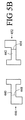
図5A、5B、及び5Cを参照すると、発光パッケージ410が記載されている。パッケージ410は、図4A、4B、及び4Cのパッケージ310と同様である。パッケージ310の要素に対応する発光パッケージ410の要素は、100だけオフセットした参照符号によって表記されている。パッケージ410は、チップキャリア414の上部主表面上に配置された導電層420、422、424に電気的に接続されている4つの発光チップ412A、412B、412C、412Dを含む。導電層420、422、424は、層424が層420、422の間に配置されて直列相互接続端子として機能するように構成されている。導電層420、424は、ギャップ428によって隔てられ、他方、導電層422、424はギャップ430によって隔てられている。発光チップ412A、412Bは非反転方向で構成され、各チップの導電性裏面は、導電層420に接合される電極としての役割を果たす。発光チップ412C、412Dは同様に非反転方向で構成され、各チップの導電性裏面は、導電層424に接合される電極としての役割を果たす。発光チップ412Aの表側電極は、ワイヤボンディング490Aによってギャップ428を跨いで導電層424にワイヤボンディングされる。同様に発光チップ412Bの表側電極は、ワイヤボンディング490Bによってギャップ428を跨いで導電層424にワイヤボンディングされる。発光チップ412Cの表側電極は、ワイヤボンディング490Cによってギャップ430を跨いで導電層422にワイヤボンディングされる。発光チップ412Dの表側電極は、ワイヤボンディング490Dによってギャップ430を跨いで導電層422にワイヤボンディングされる。このように、発光チップ412A、412Bは互いに電気的に並列接続され、同様に発光チップ412C、412Dは互いに電気的に並列接続されている。チップ412A、412Bの並列組合せは、直列相互接続端子導電層424を介してチップ412C、412Dの並列組合せに電気的に直列接続されている。
With reference to FIGS. 5A, 5B, and 5C, a
リードフレーム要素440、442は、チップキャリア414の上部主表面上に配置された導電層420、422とハンダ付けされ、或いは電気的に接触し接合される。パッケージ10、110の対応するリードフレーム要素と同様に、リードフレーム要素440、442は各々、電気リード部446、452がチップキャリア414の下部主表面とほぼ同一平面上にあるようにする曲げ部448、454を含み、その結果、発光チップパッケージ410が、リード部446、452をプリント基板又は他の支持体にハンダ付け又は接続することで表面実装可能となる。好ましくは表面実装はまた、チップキャリア414の下部主表面とプリント基板又は他の支持体との間にハンダ接合部又は他の熱接触部を形成する段階を含む。カプセル化材料又は蛍光体は発光パッケージ410に含まれていないが、カプセル化材料、蛍光体、光学構成要素、又は同様のものが任意選択的に含まれることは理解されるであろう。
The
図3及び図5において、各チップの表側電極を電気接続するために単一のワイヤボンディングが用いられ、各チップの第2の電極は、チップの導電性裏面に対応する。しかしながら、絶縁性裏面と、チップキャリアの表側主表面上に配置された導電フィルムの1つに各々ワイヤボンディングされている2つの表側コンタクトとを利用することも企図される。 3 and 5, a single wire bond is used to electrically connect the front side electrodes of each chip, and the second electrode of each chip corresponds to the conductive back side of the chip. However, it is also contemplated to utilize an insulating back surface and two front contacts each wire bonded to one of the conductive films disposed on the front major surface of the chip carrier.
本明細書で説明される発光パッケージは、電子パッケージ化処理を用いて適切に組立てられる。1つの例示的なプロセスは以下の通りである。プロセスは、好ましくは多数の発光パッケージを生成するためにダイスされることになるチップキャリアウェーハで始まり、これらの発光パッケージは、各々がチップキャリアウェーハからダイスされたチップキャリアを含む。チップキャリアが導電性である場合には、少なくとも上部主表面上に電気絶縁層を形成するように被覆、酸化、或いは他の方法で処理されるのが好ましい。導電層間に電気隔離ギャップを形成するリソグラフィ技術に関連する金属蒸着、電気メッキ、又は同様のものを用いてチップキャリアの上部主表面上に2つ又はそれ以上のパターン化導電層が形成される。これらのパターン化導電層は、図1のパッケージの層20、22のように電気端子導電層である。任意選択的にチップキャリアの下部主表面もまた金属被覆され、下部主表面を通って熱伝導性を改善するためハンダ取付を可能にする。発光チップは、フリップチップ接合、ワイヤボンディング、又は同様のものによってチップキャリアに機械的及び電気的に取付けられる。次いで、チップキャリアウェーハはダイスされ、取付けられた発光チップを有する複数のチップキャリアを生成する。
The light emitting package described herein is suitably assembled using an electronic packaging process. One exemplary process is as follows. The process preferably begins with a chip carrier wafer that will be diced to produce a number of light emitting packages, which light emitting packages each include a chip carrier diced from the chip carrier wafer. If the chip carrier is conductive, it is preferably coated, oxidized or otherwise treated to form an electrically insulating layer at least on the upper major surface. Two or more patterned conductive layers are formed on the upper major surface of the chip carrier using metal deposition, electroplating, or the like associated with lithographic techniques to form an electrical isolation gap between the conductive layers. These patterned conductive layers are electrical terminal conductive layers, such as the
ダイシングによって生成された各チップキャリアは、以下のような例示的なプロセスで処理される。チップキャリアの上部主表面は、リードフレームにハンダ付けされる。好ましくは、2つのリードフレーム要素はこのハンダ付け中にタブ又は他の固定具によって共に固定され、1つの実施形態では、幾つかのこのようなリードフレームが自動的処理を容易にするために線形又は二次元アレイで共に固定される。発光チップ、チップキャリアの上部主表面、及びリードフレームの一部を覆ってカプセル化材料を形成するためにトランスファー成形プロセスが用いられる。成形ダイは、リード部及びチップキャリアの下部主表面が、成形されたカプセル化材料の外側に延びるように設計される。次いで、リードフレームのタブがカット又はトリミングされ、リードフレーム要素を電気的に隔て、ハンダ付け又は同様のものによる表面実装に好適な最終の発光パッケージが生成される。 Each chip carrier generated by dicing is processed by the following exemplary process. The upper main surface of the chip carrier is soldered to the lead frame. Preferably, the two leadframe elements are secured together by a tab or other fixture during this soldering, and in one embodiment, several such leadframes are linear to facilitate automatic processing. Or they are fixed together in a two-dimensional array. A transfer molding process is used to form an encapsulating material over the light emitting chip, the top major surface of the chip carrier, and a portion of the lead frame. The molding die is designed such that the lead and the lower major surface of the chip carrier extend outside the molded encapsulant material. The leadframe tabs are then cut or trimmed to electrically separate the leadframe elements to produce a final light emitting package suitable for surface mounting by soldering or the like.
本発明を好ましい実施形態を参照しながら説明してきた。明らかなこととして、前述の詳細な説明を読み理解すると、当業者には修正及び変更が想起されることになる。このような修正及び変更が添付の請求項又はその均等物の範囲内にある限り、本発明は全てのこのような修正及び変更を含むものと解釈すべきであるものとする。 The invention has been described with reference to the preferred embodiments. Obviously, modifications and alterations will occur to those of ordinary skill in the art upon reading and understanding the foregoing detailed description. To the extent that such modifications and changes fall within the scope of the appended claims or their equivalents, the present invention should be construed as including all such modifications and changes.
10 表面実装発光パッケージ
12 発光チップ
14 チップキャリア
40、42 リードフレーム要素
60 カプセル化材料
70 プリント基板
DESCRIPTION OF
Claims (4)
前記熱伝導性チップキャリアの上部主表面に取付けられた少なくとも2つの発光チップと、
前記チップキャリアの上部主表面に取付けられたリードフレームであって、前記チップキャリアの前記上部主表面から延びる第1リードフレーム要素と、前記チップキャリアの前記上部主表面から延びる第2リードフレーム要素とから成り、前記チップキャリアの下部主表面に接触していないリードフレームと、
前記チップキャリアの上部主表面上に配置された、導電性材料の複数の区域と、
を備え、
前記複数の区域が、第1の電気端子を形成する導電性材料の第1の区域と、前記第1の区域から電気的に絶縁され、前記第1の電気端子と反対の電気極性の第2の電気端子を形成する導電性材料の第2の区域と、導電性材料の前記第1の区域及び前記第2の区域から電気的に絶縁されており、直列相互接続端子を定めている導電性材料の第3の区域と:を含み、
前記リードフレームの前記第1のリードフレーム要素が、前記導電性材料の第1の区域と電気的に接触して、前記上部主表面へ取り付けられており、前記リードフレームが前記第1の電気端子に取り付けられており、
前記リードフレームの前記第2のリードフレーム要素が、前記導電性材料の第2の区域と電気的に接触して、前記上部主表面へ取り付けられており、前記リードフレームが前記第2の電気端子に取り付けられており、
前記少なくとも2つの発光チップの内の第1の発光チップの電極が、前記第1の電気端子及び前記直列相互接続端子と電気的に接続されており、
前記少なくとも2つの発光チップの内の第2の発光チップの電極が、前記第2の電気端子及び前記直列相互接続端子と電気的に接続されており、
前記第1の発光チップが、前記第1の区域と前記第3の区域の間のギャップを跨いでフリップチップ接合されており、前記第1の発光チップの電極が、ワイヤボンディング無しに、前記第1の区域及び前記第3の区域の前記導電性材料に接合されており、前記第2の発光チップが、前記第3の区域と前記第2の区域の間のギャップを跨いでフリップチップ接合されており、前記第2の発光チップの電極が、ワイヤボンディング無しに、前記第3の区域及び前記第2の区域の前記導電性材料に接合されている、ことを特徴とする発光パッケージ。 A chip carrier having upper and lower main surfaces;
At least two light emitting chips attached to the top major surface of the thermally conductive chip carrier;
A lead frame attached to an upper main surface of the chip carrier, the first lead frame element extending from the upper main surface of the chip carrier, and the second lead frame element extending from the upper main surface of the chip carrier. A lead frame not in contact with the lower main surface of the chip carrier,
A plurality of areas of conductive material disposed on an upper major surface of the chip carrier;
With
The plurality of areas are a first area of conductive material forming a first electrical terminal, and a second area of electrical polarity that is electrically isolated from the first area and opposite the first electrical terminal. A second region of conductive material forming a plurality of electrical terminals; and a conductive material that is electrically isolated from the first region and the second region of conductive material to define a series interconnect terminal A third area of material and comprising:
The first lead frame element of the lead frame is attached to the upper major surface in electrical contact with the first area of the conductive material, the lead frame being the first electrical terminal. Attached to the
The second lead frame element of the lead frame is attached to the upper major surface in electrical contact with the second area of the conductive material, the lead frame being the second electrical terminal. Attached to the
Of the at least two light emitting chips, the electrode of the first light emitting chip is electrically connected to the first electrical terminal and the series interconnection terminal,
Of the at least two light emitting chips, an electrode of a second light emitting chip is electrically connected to the second electrical terminal and the series interconnection terminal,
The first light emitting chip is flip-chip bonded across the gap between the first area and the third area, and the electrode of the first light emitting chip is connected to the first light emitting chip without wire bonding. The second light emitting chip is flip-chip bonded across the gap between the third area and the second area. The electrode of the second light emitting chip is bonded to the conductive material in the third area and the second area without wire bonding.
Applications Claiming Priority (3)
| Application Number | Priority Date | Filing Date | Title |
|---|---|---|---|
| US52796903P | 2003-12-09 | 2003-12-09 | |
| US60/527,969 | 2003-12-09 | ||
| PCT/US2004/041392 WO2005057672A2 (en) | 2003-12-09 | 2004-12-09 | Surface mount light emitting chip package |
Publications (3)
| Publication Number | Publication Date |
|---|---|
| JP2007514320A JP2007514320A (en) | 2007-05-31 |
| JP2007514320A5 JP2007514320A5 (en) | 2008-02-07 |
| JP5349755B2 true JP5349755B2 (en) | 2013-11-20 |
Family
ID=34676803
Family Applications (1)
| Application Number | Title | Priority Date | Filing Date |
|---|---|---|---|
| JP2006544014A Expired - Fee Related JP5349755B2 (en) | 2003-12-09 | 2004-12-09 | Surface mount light emitting chip package |
Country Status (6)
| Country | Link |
|---|---|
| US (1) | US20080035947A1 (en) |
| EP (1) | EP1700350A2 (en) |
| JP (1) | JP5349755B2 (en) |
| KR (1) | KR101311635B1 (en) |
| CN (1) | CN1961431A (en) |
| WO (1) | WO2005057672A2 (en) |
Families Citing this family (34)
| Publication number | Priority date | Publication date | Assignee | Title |
|---|---|---|---|---|
| US10340424B2 (en) | 2002-08-30 | 2019-07-02 | GE Lighting Solutions, LLC | Light emitting diode component |
| KR100623024B1 (en) * | 2004-06-10 | 2006-09-19 | 엘지전자 주식회사 | High Power LED Package |
| KR101232505B1 (en) * | 2005-06-30 | 2013-02-12 | 엘지디스플레이 주식회사 | Method of fabrication light emission diode package and backlight unit and liquid crystal display device |
| DE102006000476A1 (en) * | 2005-09-22 | 2007-05-24 | Lexedis Lighting Gesmbh | Light emitting device |
| JP5080758B2 (en) * | 2005-10-07 | 2012-11-21 | 日立マクセル株式会社 | Semiconductor device |
| JP4483771B2 (en) * | 2005-11-21 | 2010-06-16 | パナソニック電工株式会社 | Light emitting device and manufacturing method thereof |
| JP4483772B2 (en) * | 2005-11-21 | 2010-06-16 | パナソニック電工株式会社 | Light emitting device and manufacturing method thereof |
| JP2007201420A (en) * | 2005-12-27 | 2007-08-09 | Sharp Corp | Semiconductor light-emitting device, semiconductor light-emitting element, and method of manufacturing semiconductor light-emitting device |
| JP2007180234A (en) * | 2005-12-27 | 2007-07-12 | Matsushita Electric Ind Co Ltd | Light-emitting source, and luminaire |
| US7842960B2 (en) | 2006-09-06 | 2010-11-30 | Lumination Llc | Light emitting packages and methods of making same |
| KR100826982B1 (en) * | 2006-12-29 | 2008-05-02 | 주식회사 하이닉스반도체 | Memory module |
| US9041042B2 (en) * | 2010-09-20 | 2015-05-26 | Cree, Inc. | High density multi-chip LED devices |
| US9640737B2 (en) | 2011-01-31 | 2017-05-02 | Cree, Inc. | Horizontal light emitting diodes including phosphor particles |
| US9754926B2 (en) | 2011-01-31 | 2017-09-05 | Cree, Inc. | Light emitting diode (LED) arrays including direct die attach and related assemblies |
| GB2458972B (en) * | 2008-08-05 | 2010-09-01 | Photonstar Led Ltd | Thermally optimised led chip-on-board module |
| JP2010177375A (en) * | 2009-01-28 | 2010-08-12 | Citizen Electronics Co Ltd | Light-emitting device and manufacturing method of the same |
| US8593040B2 (en) | 2009-10-02 | 2013-11-26 | Ge Lighting Solutions Llc | LED lamp with surface area enhancing fins |
| TWI390703B (en) * | 2010-01-28 | 2013-03-21 | Advanced Optoelectronic Tech | Top view type of light emitting diode package structure and fabrication thereof |
| US8506105B2 (en) | 2010-08-25 | 2013-08-13 | Generla Electric Company | Thermal management systems for solid state lighting and other electronic systems |
| US9053958B2 (en) * | 2011-01-31 | 2015-06-09 | Cree, Inc. | Light emitting diode (LED) arrays including direct die attach and related assemblies |
| US9831220B2 (en) | 2011-01-31 | 2017-11-28 | Cree, Inc. | Light emitting diode (LED) arrays including direct die attach and related assemblies |
| DE102011079708B4 (en) | 2011-07-25 | 2022-08-11 | Osram Gmbh | SUPPORT DEVICE, ELECTRICAL DEVICE WITH SUPPORT DEVICE, AND METHOD FOR MANUFACTURING SAME |
| US9500355B2 (en) | 2012-05-04 | 2016-11-22 | GE Lighting Solutions, LLC | Lamp with light emitting elements surrounding active cooling device |
| US10439112B2 (en) * | 2012-05-31 | 2019-10-08 | Cree, Inc. | Light emitter packages, systems, and methods having improved performance |
| US9349929B2 (en) | 2012-05-31 | 2016-05-24 | Cree, Inc. | Light emitter packages, systems, and methods |
| USD749051S1 (en) | 2012-05-31 | 2016-02-09 | Cree, Inc. | Light emitting diode (LED) package |
| CN103307483A (en) * | 2013-06-03 | 2013-09-18 | 杭州杭科光电股份有限公司 | LED light source module based on printed circuit board |
| US10663142B2 (en) | 2014-03-31 | 2020-05-26 | Bridgelux Inc. | Light-emitting device with reflective ceramic substrate |
| KR102189129B1 (en) * | 2014-06-02 | 2020-12-09 | 엘지이노텍 주식회사 | Light emitting device module |
| JP2014225022A (en) * | 2014-06-18 | 2014-12-04 | 株式会社東芝 | Illumination device, imaging device, and portable terminal |
| DE102016100320A1 (en) | 2016-01-11 | 2017-07-13 | Osram Opto Semiconductors Gmbh | Optoelectronic component, optoelectronic module and method for producing an optoelectronic component |
| JP6704175B2 (en) * | 2016-01-27 | 2020-06-03 | パナソニックIpマネジメント株式会社 | LED module and lighting fixture using the same |
| KR102608419B1 (en) * | 2016-07-12 | 2023-12-01 | 삼성디스플레이 주식회사 | Display Apparatus and Method for manufacturing the same |
| US11576262B2 (en) | 2020-04-27 | 2023-02-07 | Apple Inc. | Fabric-mounted components |
Family Cites Families (33)
| Publication number | Priority date | Publication date | Assignee | Title |
|---|---|---|---|---|
| JPS63107483U (en) * | 1986-12-29 | 1988-07-11 | ||
| JPH06302757A (en) * | 1993-04-15 | 1994-10-28 | Ibiden Co Ltd | Electronic component mounting device and packaging method thereof |
| JPH073141U (en) * | 1993-06-04 | 1995-01-17 | 沖電気工業株式会社 | High-speed / high-frequency IC component board structure |
| US5369529A (en) * | 1993-07-19 | 1994-11-29 | Motorola, Inc. | Reflective optoelectronic interface device and method of making |
| US5428704A (en) * | 1993-07-19 | 1995-06-27 | Motorola, Inc. | Optoelectronic interface and method of making |
| US5384873A (en) * | 1993-10-04 | 1995-01-24 | Motorola, Inc. | Optical interface unit and method of making |
| JP2646988B2 (en) * | 1993-12-24 | 1997-08-27 | 日本電気株式会社 | Resin-sealed semiconductor device |
| JPH088355A (en) * | 1994-06-21 | 1996-01-12 | Fujitsu Ltd | Semiconductor device |
| JP2546195B2 (en) * | 1994-10-06 | 1996-10-23 | 日本電気株式会社 | Resin-sealed semiconductor device |
| KR100214463B1 (en) * | 1995-12-06 | 1999-08-02 | 구본준 | Lead frame of clip type and method manufacture of the package |
| JPH09270537A (en) * | 1996-04-01 | 1997-10-14 | Nichia Chem Ind Ltd | Photoelectric conversion device |
| WO1998020718A1 (en) * | 1996-11-06 | 1998-05-14 | Siliconix Incorporated | Heat sink-lead frame structure |
| US6093940A (en) * | 1997-04-14 | 2000-07-25 | Rohm Co., Ltd. | Light-emitting diode chip component and a light-emitting device |
| JP3741512B2 (en) * | 1997-04-14 | 2006-02-01 | ローム株式会社 | LED chip parts |
| EP1004145B1 (en) * | 1997-07-29 | 2005-06-01 | Osram Opto Semiconductors GmbH | Optoelectronic component |
| US6005262A (en) * | 1997-08-20 | 1999-12-21 | Lucent Technologies Inc. | Flip-chip bonded VCSEL CMOS circuit with silicon monitor detector |
| JPH11168235A (en) * | 1997-12-05 | 1999-06-22 | Toyoda Gosei Co Ltd | Light emitting diode |
| US6184544B1 (en) * | 1998-01-29 | 2001-02-06 | Rohm Co., Ltd. | Semiconductor light emitting device with light reflective current diffusion layer |
| JP3893735B2 (en) * | 1998-04-24 | 2007-03-14 | 松下電器産業株式会社 | Light emitting device |
| US5914501A (en) * | 1998-08-27 | 1999-06-22 | Hewlett-Packard Company | Light emitting diode assembly having integrated electrostatic discharge protection |
| US6392778B1 (en) * | 1999-03-17 | 2002-05-21 | Koninklijke Philips Electronics N.V. | Opto-electronic element |
| JP3964590B2 (en) * | 1999-12-27 | 2007-08-22 | 東芝電子エンジニアリング株式会社 | Optical semiconductor package |
| JP2001223388A (en) * | 2000-02-09 | 2001-08-17 | Nippon Leiz Co Ltd | Light source device |
| WO2001059851A1 (en) * | 2000-02-09 | 2001-08-16 | Nippon Leiz Corporation | Light source |
| US6384473B1 (en) * | 2000-05-16 | 2002-05-07 | Sandia Corporation | Microelectronic device package with an integral window |
| JP4386552B2 (en) * | 2000-08-03 | 2009-12-16 | ローム株式会社 | Structure of light emitting / receiving semiconductor device |
| JP5110744B2 (en) * | 2000-12-21 | 2012-12-26 | フィリップス ルミレッズ ライティング カンパニー リミテッド ライアビリティ カンパニー | Light emitting device and manufacturing method thereof |
| DE10196351D2 (en) * | 2001-04-18 | 2004-04-15 | Infineon Technologies Ag | Transmitter module for optical signal transmission |
| JP2003008071A (en) * | 2001-06-22 | 2003-01-10 | Stanley Electric Co Ltd | Led lamp using led substrate assembly |
| US6498355B1 (en) * | 2001-10-09 | 2002-12-24 | Lumileds Lighting, U.S., Llc | High flux LED array |
| JP4211359B2 (en) * | 2002-03-06 | 2009-01-21 | 日亜化学工業株式会社 | Manufacturing method of semiconductor device |
| JP3088472U (en) * | 2002-03-08 | 2002-09-13 | 東貝光電科技股▲ふん▼有限公司 | Light emitting diode |
| JP3877642B2 (en) * | 2002-05-21 | 2007-02-07 | ローム株式会社 | Semiconductor device using semiconductor chip |
-
2004
- 2004-12-09 JP JP2006544014A patent/JP5349755B2/en not_active Expired - Fee Related
- 2004-12-09 KR KR1020067013794A patent/KR101311635B1/en active IP Right Grant
- 2004-12-09 CN CNA2004800409569A patent/CN1961431A/en active Pending
- 2004-12-09 EP EP04813682A patent/EP1700350A2/en not_active Withdrawn
- 2004-12-09 WO PCT/US2004/041392 patent/WO2005057672A2/en active Application Filing
- 2004-12-09 US US10/582,377 patent/US20080035947A1/en not_active Abandoned
Also Published As
| Publication number | Publication date |
|---|---|
| JP2007514320A (en) | 2007-05-31 |
| KR101311635B1 (en) | 2013-09-26 |
| KR20060134969A (en) | 2006-12-28 |
| WO2005057672A2 (en) | 2005-06-23 |
| US20080035947A1 (en) | 2008-02-14 |
| CN1961431A (en) | 2007-05-09 |
| EP1700350A2 (en) | 2006-09-13 |
| WO2005057672A3 (en) | 2006-04-06 |
Similar Documents
| Publication | Publication Date | Title |
|---|---|---|
| JP5349755B2 (en) | Surface mount light emitting chip package | |
| JP5746076B2 (en) | Semiconductor light emitting device package submount and semiconductor light emitting device package including the submount | |
| US7244965B2 (en) | Power surface mount light emitting die package | |
| US8044423B2 (en) | Light emitting device package | |
| KR100863612B1 (en) | Light emitting device | |
| US8860069B2 (en) | Light-emitting device package having a molding member with a low profile, and method of manufacturing the same | |
| JP2013153195A (en) | Light emitting element package | |
| US8901580B2 (en) | Package for mounting electronic components, electronic apparatus, and method for manufacturing the package | |
| TWM379163U (en) | Packaging apparatus for high power and high orientation matrix semiconductor light-emitting devices | |
| KR101555300B1 (en) | Semiconductor power module package having external boding area | |
| US20130307014A1 (en) | Semiconductor light emitting device | |
| WO2010050067A1 (en) | Substrate for light emitting element package, and light emitting element package | |
| US20120217657A1 (en) | Multi-chip module package | |
| KR20110035190A (en) | Light emitting apparatus | |
| KR100447413B1 (en) | Semiconductor light emitting device | |
| KR20110035189A (en) | Light emitting apparatus | |
| US8482019B2 (en) | Electronic light emitting device and method for fabricating the same | |
| US11935806B2 (en) | Semiconductor device and method for manufacturing semiconductor device | |
| KR20130015482A (en) | Lighting emitting diode package and method for manufacturing the same | |
| KR20110034123A (en) | Light emitting device package | |
| KR100481926B1 (en) | General chip type semiconductor package and flip chip type semiconductor package and manufacturing method | |
| KR20080087405A (en) | Light emitting diode package and method for fabricating the same diode |
Legal Events
| Date | Code | Title | Description |
|---|---|---|---|
| A521 | Request for written amendment filed |
Free format text: JAPANESE INTERMEDIATE CODE: A523 Effective date: 20071207 |
|
| A621 | Written request for application examination |
Free format text: JAPANESE INTERMEDIATE CODE: A621 Effective date: 20071207 |
|
| A131 | Notification of reasons for refusal |
Free format text: JAPANESE INTERMEDIATE CODE: A131 Effective date: 20100802 |
|
| A601 | Written request for extension of time |
Free format text: JAPANESE INTERMEDIATE CODE: A601 Effective date: 20101102 |
|
| A602 | Written permission of extension of time |
Free format text: JAPANESE INTERMEDIATE CODE: A602 Effective date: 20101110 |
|
| A521 | Request for written amendment filed |
Free format text: JAPANESE INTERMEDIATE CODE: A523 Effective date: 20110201 |
|
| A131 | Notification of reasons for refusal |
Free format text: JAPANESE INTERMEDIATE CODE: A131 Effective date: 20111226 |
|
| A601 | Written request for extension of time |
Free format text: JAPANESE INTERMEDIATE CODE: A601 Effective date: 20120326 |
|
| A602 | Written permission of extension of time |
Free format text: JAPANESE INTERMEDIATE CODE: A602 Effective date: 20120402 |
|
| A521 | Request for written amendment filed |
Free format text: JAPANESE INTERMEDIATE CODE: A523 Effective date: 20120419 |
|
| A131 | Notification of reasons for refusal |
Free format text: JAPANESE INTERMEDIATE CODE: A131 Effective date: 20121009 |
|
| A601 | Written request for extension of time |
Free format text: JAPANESE INTERMEDIATE CODE: A601 Effective date: 20130109 |
|
| A602 | Written permission of extension of time |
Free format text: JAPANESE INTERMEDIATE CODE: A602 Effective date: 20130117 |
|
| A521 | Request for written amendment filed |
Free format text: JAPANESE INTERMEDIATE CODE: A523 Effective date: 20130313 |
|
| A131 | Notification of reasons for refusal |
Free format text: JAPANESE INTERMEDIATE CODE: A131 Effective date: 20130401 |
|
| A521 | Request for written amendment filed |
Free format text: JAPANESE INTERMEDIATE CODE: A523 Effective date: 20130628 |
|
| TRDD | Decision of grant or rejection written | ||
| A01 | Written decision to grant a patent or to grant a registration (utility model) |
Free format text: JAPANESE INTERMEDIATE CODE: A01 Effective date: 20130722 |
|
| A61 | First payment of annual fees (during grant procedure) |
Free format text: JAPANESE INTERMEDIATE CODE: A61 Effective date: 20130821 |
|
| R150 | Certificate of patent or registration of utility model |
Ref document number: 5349755 Country of ref document: JP Free format text: JAPANESE INTERMEDIATE CODE: R150 Free format text: JAPANESE INTERMEDIATE CODE: R150 |
|
| R250 | Receipt of annual fees |
Free format text: JAPANESE INTERMEDIATE CODE: R250 |
|
| R250 | Receipt of annual fees |
Free format text: JAPANESE INTERMEDIATE CODE: R250 |
|
| R250 | Receipt of annual fees |
Free format text: JAPANESE INTERMEDIATE CODE: R250 |
|
| R250 | Receipt of annual fees |
Free format text: JAPANESE INTERMEDIATE CODE: R250 |
|
| R250 | Receipt of annual fees |
Free format text: JAPANESE INTERMEDIATE CODE: R250 |
|
| S531 | Written request for registration of change of domicile |
Free format text: JAPANESE INTERMEDIATE CODE: R313531 |
|
| S533 | Written request for registration of change of name |
Free format text: JAPANESE INTERMEDIATE CODE: R313533 |
|
| R350 | Written notification of registration of transfer |
Free format text: JAPANESE INTERMEDIATE CODE: R350 |
|
| R250 | Receipt of annual fees |
Free format text: JAPANESE INTERMEDIATE CODE: R250 |
|
| LAPS | Cancellation because of no payment of annual fees |