JP5347363B2 - WDM optical transmission system and control method thereof - Google Patents
WDM optical transmission system and control method thereof Download PDFInfo
- Publication number
- JP5347363B2 JP5347363B2 JP2008197392A JP2008197392A JP5347363B2 JP 5347363 B2 JP5347363 B2 JP 5347363B2 JP 2008197392 A JP2008197392 A JP 2008197392A JP 2008197392 A JP2008197392 A JP 2008197392A JP 5347363 B2 JP5347363 B2 JP 5347363B2
- Authority
- JP
- Japan
- Prior art keywords
- wdm
- node
- light intensity
- light
- optical
- Prior art date
- Legal status (The legal status is an assumption and is not a legal conclusion. Google has not performed a legal analysis and makes no representation as to the accuracy of the status listed.)
- Expired - Fee Related
Links
Images


Classifications
-
- H—ELECTRICITY
- H04—ELECTRIC COMMUNICATION TECHNIQUE
- H04J—MULTIPLEX COMMUNICATION
- H04J14/00—Optical multiplex systems
- H04J14/02—Wavelength-division multiplex systems
- H04J14/0221—Power control, e.g. to keep the total optical power constant
-
- H—ELECTRICITY
- H04—ELECTRIC COMMUNICATION TECHNIQUE
- H04B—TRANSMISSION
- H04B10/00—Transmission systems employing electromagnetic waves other than radio-waves, e.g. infrared, visible or ultraviolet light, or employing corpuscular radiation, e.g. quantum communication
- H04B10/07—Arrangements for monitoring or testing transmission systems; Arrangements for fault measurement of transmission systems
- H04B10/075—Arrangements for monitoring or testing transmission systems; Arrangements for fault measurement of transmission systems using an in-service signal
- H04B10/079—Arrangements for monitoring or testing transmission systems; Arrangements for fault measurement of transmission systems using an in-service signal using measurements of the data signal
- H04B10/0795—Performance monitoring; Measurement of transmission parameters
- H04B10/07955—Monitoring or measuring power
-
- H—ELECTRICITY
- H04—ELECTRIC COMMUNICATION TECHNIQUE
- H04B—TRANSMISSION
- H04B10/00—Transmission systems employing electromagnetic waves other than radio-waves, e.g. infrared, visible or ultraviolet light, or employing corpuscular radiation, e.g. quantum communication
- H04B10/29—Repeaters
- H04B10/291—Repeaters in which processing or amplification is carried out without conversion of the main signal from optical form
- H04B10/293—Signal power control
- H04B10/2933—Signal power control considering the whole optical path
- H04B10/2939—Network aspects
-
- H—ELECTRICITY
- H04—ELECTRIC COMMUNICATION TECHNIQUE
- H04J—MULTIPLEX COMMUNICATION
- H04J14/00—Optical multiplex systems
- H04J14/02—Wavelength-division multiplex systems
- H04J14/0201—Add-and-drop multiplexing
- H04J14/0202—Arrangements therefor
- H04J14/0204—Broadcast and select arrangements, e.g. with an optical splitter at the input before adding or dropping
-
- H—ELECTRICITY
- H04—ELECTRIC COMMUNICATION TECHNIQUE
- H04J—MULTIPLEX COMMUNICATION
- H04J14/00—Optical multiplex systems
- H04J14/02—Wavelength-division multiplex systems
- H04J14/0201—Add-and-drop multiplexing
- H04J14/0202—Arrangements therefor
- H04J14/0206—Express channels arrangements
-
- H—ELECTRICITY
- H04—ELECTRIC COMMUNICATION TECHNIQUE
- H04J—MULTIPLEX COMMUNICATION
- H04J14/00—Optical multiplex systems
- H04J14/02—Wavelength-division multiplex systems
- H04J14/0201—Add-and-drop multiplexing
- H04J14/0202—Arrangements therefor
- H04J14/021—Reconfigurable arrangements, e.g. reconfigurable optical add/drop multiplexers [ROADM] or tunable optical add/drop multiplexers [TOADM]
- H04J14/0212—Reconfigurable arrangements, e.g. reconfigurable optical add/drop multiplexers [ROADM] or tunable optical add/drop multiplexers [TOADM] using optical switches or wavelength selective switches [WSS]
-
- H—ELECTRICITY
- H04—ELECTRIC COMMUNICATION TECHNIQUE
- H04J—MULTIPLEX COMMUNICATION
- H04J14/00—Optical multiplex systems
- H04J14/02—Wavelength-division multiplex systems
- H04J14/0201—Add-and-drop multiplexing
- H04J14/0202—Arrangements therefor
- H04J14/0213—Groups of channels or wave bands arrangements
-
- H—ELECTRICITY
- H04—ELECTRIC COMMUNICATION TECHNIQUE
- H04J—MULTIPLEX COMMUNICATION
- H04J14/00—Optical multiplex systems
- H04J14/02—Wavelength-division multiplex systems
- H04J14/0201—Add-and-drop multiplexing
- H04J14/0202—Arrangements therefor
- H04J14/0209—Multi-stage arrangements, e.g. by cascading multiplexers or demultiplexers
Description
本発明は、波長の異なる複数の光信号を含んだ波長多重(WDM:Wavelength Division Multiplexing)光を中継伝送するWDM光伝送システムおよびその制御方法に関する。さらに、本発明は、WDM光を各波長の光信号に分波して所定の処理を行うノードを伝送路上に備えたWDM光伝送システムおよびその制御方法を含む。 The present invention relates to a WDM optical transmission system that relays and transmits wavelength division multiplexing (WDM) light including a plurality of optical signals having different wavelengths, and a control method thereof. Furthermore, the present invention includes a WDM optical transmission system provided with a node on a transmission line for performing predetermined processing by demultiplexing WDM light into optical signals of respective wavelengths, and a control method therefor.
伝送路上に配置された光中継器でWDM光を増幅しながら中継伝送するWDM光伝送システムにおいて、光中継器で増幅されたWDM光が該光中継器の出力側に接続する伝送路ファイバに入力される強度(以下、ファイバ入力光強度とする)は、システムの特性を決める重要なパラメータの1つである。このファイバ入力光強度が低くなり過ぎると、光信号対雑音比(OSNR:Optical Signal to Noise Ratio)が悪くなる。一方、ファイバ入力光強度が高くなり過ぎると、光ファイバ内の非線形効果により伝送品質の劣化が生じる。このため、一般に光中継器では、光増幅器を用いて増幅したWDM光の強度をモニタし、そのモニタ結果に応じてWDM光の1チャネル当たりの光強度が一定となるように、前記光増幅器の制御が行われる。なお、前記チャネルは、WDM光に含まれる各波長の光信号を意味する。 In a WDM optical transmission system that repeats and transmits WDM light while amplifying WDM light using an optical repeater arranged on the transmission line, the WDM light amplified by the optical repeater is input to a transmission line fiber connected to the output side of the optical repeater. The intensity to be applied (hereinafter referred to as fiber input light intensity) is one of important parameters that determine the characteristics of the system. If the fiber input light intensity becomes too low, the optical signal to noise ratio (OSNR) deteriorates. On the other hand, if the fiber input light intensity becomes too high, the transmission quality deteriorates due to the nonlinear effect in the optical fiber. Therefore, in general, in an optical repeater, the intensity of WDM light amplified using an optical amplifier is monitored, and the light intensity per channel of the WDM light is constant according to the monitoring result. Control is performed. The channel means an optical signal of each wavelength included in the WDM light.
しかしながら、例えば図14の上段に示すように、送信局101および受信局102の間の伝送路103上に複数の光中継器104が配置され、各光中継器104でWDM光を順次増幅して伝送するシステムでは、各光中継器104内の光増幅器で発生する光雑音が累積されるようになる。このため、各光中継器104において1チャネル当たりの光強度を一定にする制御が行われていても、図14の下段に示すように、各チャネルに含まれる信号成分および雑音成分のうちの信号成分の割合が、中継数の増加に伴って徐々に減少してしまう。
However, for example, as shown in the upper part of FIG. 14, a plurality of
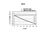
図15は、各中継区間(スパン)の伝送路に入力されるWDM光について、信号成分の光強度と雑音成分の光強度の割合の変化をスパン数に応じて示した一例である。また、図16は、1チャネルにおける信号光強度の変化をスパン数に応じて示した一例である。各図の例のように、WDM光の各チャネルは、信号成分および雑音成分を合わせた光強度(以下、トータル光強度とする)が一定に制御されていても、スパン数の増加と伴に雑音光強度は増大し、信号光強度は減少する。このため、トータル光強度の一定制御下で各チャネルの受信処理を正常に行うことのできる所要の信号光強度(図16の丸印)よりも実際の信号光強度(図16の四角印)が小さくなり、その差はスパン数の増加に応じて拡大して行く。 FIG. 15 is an example showing a change in the ratio of the light intensity of the signal component and the light intensity of the noise component according to the number of spans for the WDM light input to the transmission path of each relay section (span). FIG. 16 is an example showing a change in signal light intensity in one channel according to the number of spans. As in the examples in each figure, each channel of WDM light has an increased number of spans even if the light intensity of the signal component and noise component (hereinafter referred to as total light intensity) is controlled to be constant. The noise light intensity increases and the signal light intensity decreases. For this reason, the actual signal light intensity (square mark in FIG. 16) is higher than the required signal light intensity (circle mark in FIG. 16) that allows normal reception processing of each channel under constant control of the total light intensity. The difference becomes smaller, and the difference increases as the number of spans increases.
上記のようなOSNRの劣化を低減するための従来技術としては、例えば図17に示すように、各光中継器における光増幅器の制御について、スパン数の増加による雑音光強度の増大分に対応させて、1チャネル当たりのトータル光強度の制御目標値を補正する手法が提案されている(例えば、特許文献1参照)。この従来技術によれば、図18に示すように、スパン数の増加により雑音光強度が大きくなっても信号光強度は一定のレベルに保たれるため、スパン数に関係なく所要の信号光強度を実現することができる。
しかしながら、上記のようなトータル光強度の制御目標値の補正を行ってOSNRの劣化を抑えるようにした従来のWDM光伝送システムについては、伝送路上に、WDM光の一括増幅を行う光中継ノードだけでなく、OADM(Optical Add Drop Multiplexing)ノードなどのようにWDM光を一旦チャネル毎に分波して所要の処理を行った後に各チャネルを再び合波して伝送路に送る機能を持ったノードが含まれている場合に、非線形効果による伝送品質の劣化が生じる可能性があるという問題点がある。 However, in the conventional WDM optical transmission system in which the OSNR degradation is suppressed by correcting the control target value of the total light intensity as described above, only the optical repeater node that performs collective amplification of WDM light on the transmission path. Rather than a node such as an OADM (Optical Add Drop Multiplexing) node, it has a function of once demultiplexing WDM light for each channel, performing the required processing, and then combining the channels again and sending them to the transmission line Is included, there is a problem that transmission quality may deteriorate due to a non-linear effect.
具体的に説明すると、例えば図19の上段に示すような伝送路103上に複数のOADMノード105が配置されたWDM光伝送システムの場合、各OADMノード105では、伝送路103を伝搬したWDM光が入力側の光増幅器で所要のレベルまで増幅された後にOADMユニットに与えられる。OADMユニットでは、分波器によりWDM光がチャネル毎に分波され、各チャネルに対するアド・ドロップ処理が行われ、各々のチャネルが合波器により再び合波される。そして、OADMユニットで処理されたWDM光は、出力側の光増幅器で所要のレベルまで増幅されて伝送路103に送出される。
More specifically, for example, in the case of a WDM optical transmission system in which a plurality of
このようなOADMノード105では、OADMユニット内の分波器でWDM光がチャネル毎に分波される際に、各々のチャネルの中間の波長領域に分布する雑音成分がフィルタリングされて取り除かれる。このため、OADMノード105で処理されたWDM光に含まれる雑音光は、図19の下段に示すように各チャネルの波長幅に対応した成分だけが残るようになる。よって、OADMノード105から伝送路103に送出されるWDM光は、光増幅器を含むがOADMを含まない光中継ノード(以下、インラインアンプ(ILA:In-Line Amplifier)と呼ぶこともある)104から伝送路103に送出されるWDM光(図17の下段参照)と比べて、雑音成分が減少する。
In such an
上記のような雑音成分のフィルタリングが行われるOADMノード105に対して、前述した従来技術により光中継ノード104の場合と同様なトータル光強度の制御目標値の補正を行った場合、雑音成分の増大分が実際よりも多く見積もられるようになるため、トータル光強度の制御目標値が過剰に補正されてしまう。このように補正されたトータル光強度の制御目標値に従って、OADMノード105における出力光強度の一定制御が行われると、OADMノード105の出力側の伝送路103に入力されるWDM光の各チャネルは、信号光強度が所要のレベルよりも高くなってしまい、非線形効果による伝送品質の劣化が生じる可能性がある。
When the
図20は、伝送路上にOADMノードを多段に配置した場合における各中継区間の伝送路に入力されるWDM光について、信号成分の光強度と雑音成分の光強度の割合の変化をスパン数に応じて示した一例である。また、図21は、1チャネルにおける信号光強度の変化をスパン数に応じて示した一例である。このように、WDM光の各チャネルは、スパン数の増加と伴に雑音光強度に対する信号光強度の割合が増大し、所要の信号光強度(図21の丸印)よりも実際の信号光強度(図21の四角印)が大きくなり、その差はスパン数の増加に応じて拡大して行く。したがって、伝送路上に多数のOADMノードを含んだシステムでは非線形効果による伝送品質の劣化が発生しやすくなる。 FIG. 20 shows the change in the ratio of the light intensity of the signal component and the light intensity of the noise component according to the number of spans for the WDM light input to the transmission path of each relay section when OADM nodes are arranged in multiple stages on the transmission path. It is an example shown. FIG. 21 is an example showing changes in signal light intensity in one channel according to the number of spans. As described above, in each channel of WDM light, the ratio of the signal light intensity to the noise light intensity increases as the number of spans increases, and the actual signal light intensity is higher than the required signal light intensity (circled in FIG. 21). (Square mark in FIG. 21) increases, and the difference increases as the number of spans increases. Therefore, in a system including a large number of OADM nodes on the transmission path, transmission quality is likely to deteriorate due to nonlinear effects.
本発明は上記の問題点に着目してなされたもので、伝送路上の複数のノードに、WDM光を個々のチャネルに分波して所定の処理を行うノードが含まれていても、各ノードから出力される信号光強度を高い精度で一定に制御して、良好な伝送品質を得ることのできるWDM光伝送システムおよびその制御方法を提供することを目的とする。 The present invention has been made paying attention to the above-described problems. Even if a plurality of nodes on the transmission path include nodes that demultiplex WDM light into individual channels and perform predetermined processing, each node It is an object of the present invention to provide a WDM optical transmission system and a control method therefor that can obtain a good transmission quality by controlling the signal light intensity output from the optical signal constant with high accuracy.
上記の目的を達成するため、本WDM光伝送システムの一態様は、波長の異なる複数のチャネルを含んだWDM光が伝送される伝送路と、前記伝送路上に配置され、前記伝送路から入力されるWDM光を個々のチャネルに分波した後、該分波された各チャネルに対して波長分散の補償を行い、該波長分散補償された各チャネルを合波したWDM光を光増幅器で増幅して前記伝送路に出力する少なくとも1つの第1ノードと、前記伝送路上に配置され、前記伝送路から入力されるWDM光を個々のチャネルに分波することなく光増幅器で増幅して前記伝送路に出力する少なくとも1つの第2ノードと、を備える。また、前記第1ノードおよび前記第2ノードは、それぞれ、自ノード内の前記光増幅器で増幅されたWDM光の強度をモニタする光強度モニタと、該光強度モニタのモニタ結果に応じて、自ノードから前記伝送路に出力するWDM光の1チャネル当たりの信号成分および雑音成分を合わせたトータル光強度が予め設定した制御目標値で一定になるように前記光増幅器の利得を制御する利得制御部と、前記光強度モニタのモニタ結果を基に、WDM光の1チャネルの信号光強度および雑音光強度の割合を求め、1チャネルの信号光強度が全てのノードで一定となるように、前記利得制御部で用いるトータル光強度の制御目標値を補正する補正値算出部と、前記伝送路上の各ノードに対してノードの種別に関する情報を含むシステム管理情報を伝達することにより、各々のノードの動作状態を集中して管理するシステム管理部と、を有する。さらに、前記補正値算出部は、前記システム管理部から伝達されるノードの種別に関する情報を基に、自ノードが前記第1ノードおよび前記第2ノードのいずれに該当しているかを判別し、第1ノードに該当しているとき、WDM光を個々のチャネルに分波する際のフィルタリング特性に応じて定めたノイズカット比率を用いた計算式に従って、前記トータル光強度の制御目標値の補正を行う。 In order to achieve the above object, one aspect of the present WDM optical transmission system includes a transmission path through which WDM light including a plurality of channels having different wavelengths is transmitted, and is arranged on the transmission path and input from the transmission path. WDM light is demultiplexed into individual channels, chromatic dispersion is compensated for each demultiplexed channel, and the WDM light obtained by combining the chromatic dispersion compensated channels is amplified by an optical amplifier. At least one first node to be output to the transmission line, and the transmission line is amplified by an optical amplifier without demultiplexing the WDM light input from the transmission line into individual channels. And at least one second node that outputs to. In addition, the first node and the second node are respectively configured to monitor the intensity of the WDM light amplified by the optical amplifier in the own node and the monitoring result of the optical intensity monitor. A gain control unit for controlling the gain of the optical amplifier so that the total optical intensity of the signal component and noise component per channel of the WDM light output from the node to the transmission path is constant at a preset control target value Then, based on the monitoring result of the light intensity monitor, the ratio of the signal light intensity of one channel of WDM light and the noise light intensity is obtained, and the gain of the signal light intensity of one channel is constant at all nodes. a correction value calculating unit for correcting the control target value of the total light intensity used in the control unit, transfer the system management information including information related to the type of the node for each node of the transmission path By having and a system management section for managing concentrating the operating state of each node. Further, the correction value calculation unit determines whether the own node corresponds to the first node or the second node based on information on the type of node transmitted from the system management unit , When it corresponds to one node, the control target value of the total light intensity is corrected according to a calculation formula using a noise cut ratio determined according to a filtering characteristic when demultiplexing WDM light into individual channels. .
上記のようなWDM光伝送システムでは、伝送路上の各ノードにおいてWDM光の1チャネル当たりのトータル光強度の制御目標値の補正が行われるとき、各々のノードの補正値算出部でシステム管理部から伝達されるノードの種別に関する情報を基に自ノードの種別が判別され、チャネル毎に波長分散の補償が行われる第1ノード(分散補償ノード)に該当している場合には、ノイズカット比率を用いた計算式に従ってトータル光強度の制御目標値の補正処理が行われる。このノイズカット比率は、WDM光を個々のチャネルに分波する際のフィルタリング特性に応じて定められており、当該フィルタリングにより各チャネルの中間の波長領域に分布する雑音成分が取り除かれることによる影響が、トータル光強度の制御目標値の補正処理に反映されるようになり、従来のような過剰な補正が回避される。 In the WDM optical transmission system as described above, when correction of the control target value of the total light intensity per channel of WDM light is performed at each node on the transmission path, the correction value calculation unit of each node performs the correction from the system management unit. When the node type is determined based on the information on the node type to be transmitted and corresponds to the first node (dispersion compensation node) in which chromatic dispersion compensation is performed for each channel, the noise cut ratio is set. According to the calculation formula used, correction processing of the control target value of the total light intensity is performed. This noise cut ratio is determined according to the filtering characteristics when the WDM light is demultiplexed into individual channels, and is affected by the removal of noise components distributed in the intermediate wavelength region of each channel by the filtering. Thus, it is reflected in the correction processing of the control target value of the total light intensity, and excessive correction as in the conventional case is avoided.
したがって、本WDM光伝送システムによれば、伝送路上に第1ノードと第2ノードが混在していても、各々のノードから出力されるWDM光の各チャネルの信号光強度を高い精度で一定に制御することができるため、良好な伝送品質を実現することが可能である。 Therefore, according to the present WDM optical transmission system, even if the first node and the second node are mixed on the transmission line, the signal light intensity of each channel of the WDM light output from each node is made constant with high accuracy. Since it can be controlled, it is possible to achieve good transmission quality.
以下、本発明を実施するための最良の形態について添付図面を参照しながら説明する。
図1は、本発明によるWDM光伝送システムの一実施形態における構成を示すブロック図である。
図1において、本実施形態のWDM光伝送システムは、伝送路1上に配置される第1および第2ノードとしてのOADMノード2Aおよび光中継ノード2Bを備えると共に、これら各ノードの動作状態を集中して管理するシステム管理部3および該システム管理部3に接続された記憶部4を有する。
The best mode for carrying out the present invention will be described below with reference to the accompanying drawings.
FIG. 1 is a block diagram showing a configuration in an embodiment of a WDM optical transmission system according to the present invention.
In FIG. 1, the WDM optical transmission system of the present embodiment includes an
伝送路1は、システム上の各ノードの間を一般的な光ファイバを用いて互いに接続する。この伝送路1は、前述の図14に示した場合と同様に、その両端に送信局および受信局が接続されていてもよく、また、リング状やメッシュ状の接続形態であっても構わない。
The
OADMノード2Aは、伝送路1を伝送されるWDM光に対して各チャネルのアド・ドロップを行う機能を備えている。このOADMノード2Aの具体的な構成例が、図1の下段に拡大して示してある。この構成例では、OADMノード2Aの入力ポート11および出力ポート12の間の光路上に、入力側の光増幅器13、OADMユニット14および出力側の光増幅器15が順に配置されている。また、出力側の光増幅器15および出力ポート12の間には光分岐器16が設けられており、出力側の光増幅器15から出力ポート12に出力されるWDM光の一部が光分岐器16により取り出される。この光分岐器16の分岐ポートには光強度モニタ17、補正値算出部18および利得制御部19が順に接続されており、後で詳しく説明するように出力側の光増幅器15の利得が利得制御部19によりフィードバック制御される。
The
上記OADMノード2Aの入力側および出力側の光増幅器13,15は、入力されるWDM光の各チャネルを一括して増幅可能な公知の光増幅器である。
OADMユニット14は、入力側の光増幅器13で増幅されたWDM光を各波長の光信号(チャネル)に分波し、該各チャネルについて、当該ノードの設定でドロップ波長に割り当てられたチャネルを外部に取り出す処理、および、アド波長に割り当てられたチャネルに対して外部から与えられるアド光を挿入する処理を行い、さらに、アド・ドロップ処理された各々のチャネルを再び合波して、出力側の光増幅器15に出力する。
The
The
図2〜図5は、上記OADMユニット14の具体的な構成例を示している。図2および図3は、複数の入出力ポート間での光の経路の切り替えを分光素子および可動ミラー等を組み合わせて行う公知の波長選択スイッチ(WSS:Wavelength Selective Switch)を利用した構成例である。また、図4および図5は、一般的なアレイ導波路回折格子(AWG:Arrayed Waveguide Grating)を利用した構成例である。
2 to 5 show specific configuration examples of the
図2の構成例では、OADMユニット14に入力されるWDM光が光分岐器14Aで2つに分岐されて各WSS14B,WSS14Eに送られる。WSS14Bでは、光分岐器14Aからの分岐光に含まれる各チャネルのうちで当該ノードのドロップ波長に該当しているチャネルが複数のグループに分けて取り出された後、該各グループの光が各々に対応したWSS14Cで個々のチャネルに分離されてドロップ光として外部に出力される。一方、外部から当該ノードに与えられるアド光は、複数のグループ毎にWSS14Dで合波された後にWSS14Eに与えられる。WSS14Eでは、光分岐器14Aからの分岐光に含まれる各チャネルのうちで当該ノードのスルー波長に該当しているチャネルと、各WSS14Dからの出力光とが合波されて、出力側の光増幅器15に出力される。このOADMユニット14の構成例では、各WSS14B〜14EにおいてWDM光が合分波される際に、各々のWSSのフィルタリング特性により、各チャネルの中間の波長領域に分布する雑音成分が取り除かれる。
In the configuration example of FIG. 2, the WDM light input to the
また、上記図2のOADMユニット14に関する変形例として、図3には、ドロップ側の複数のWSS14B,14Cに代えて1つのAWG14Fを用いると共に、アド側の複数のWSS14Dに代えて1つのAWG14Gを用いた構成例が示してある。
As a modification of the
さらに、図4の構成例では、OADMユニット14に入力されるWDM光がAWG14Hに与えられることで個々のチャネルに分波され、各チャネルのうちで当該ノードのドロップ波長に該当しているチャネルがドロップ光として外部に出力されると共に、スルー波長に該当しているチャネルがAWG14Iに送られる。AWG14Iには、外部から当該ノードに与えられるアド光も入力され、AWG14Hからのスルー光とアド光が合波されて、出力側の光増幅器15に出力される。このOADMユニット14の構成例では、入力側のAWG14HでWDM光が個々のチャネルに分波される際に、該AWG14Hのフィルタリング特性により、各チャネルの中間の波長領域に分布する雑音成分が取り除かれる。
Further, in the configuration example of FIG. 4, the WDM light input to the
また、上記図4のOADMユニット14に関する変形例として、図5には、AWG14Hで分波された各チャネルを光分岐器14Jでそれぞれ2分岐し、一方の分岐光をドロップ光とすると共に、他方の分岐光をスルー光として2×1光スイッチ14Kに与え、該光スイッチ14Kでスルー光とアド光のいずれかを選択して出力側のAWG14Iに与えるようにした構成例が示してある。この図5の構成例では、各光スイッチ14Kの切替えにより、当該ノードでのスルー波長およびアド波長の設定を適宜変更することができる。
Further, as a modification of the
光分岐器16(図1の下段)は、出力側の光増幅器15で増幅されWDM光が入力され、該WDM光を所要の比率で2分岐し、一方の分岐光を出力ポート12から伝送路1に出力すると共に、他方の分岐光を光強度モニタ17に出力する。光強度モニタ17は、光分岐器16で分岐されたWDM光の強度をモニタし、そのモニタ結果を補正値算出部18に伝える。補正値算出部18は、光強度モニタ17のモニタ結果に基づいて、当該ノードから出力され伝送路1に入力されるWDM光についての1チャネル当たりのトータル光強度、OSNRおよび該チャネルの信号光強度を算出し、その計算結果を用いてトータル光強度の制御目標値の補正を行う。
The optical branching device 16 (lower stage in FIG. 1) is amplified by the
図6は、上記光強度モニタ17の具体例とそれに対応した周辺回路の構成を示す図である。図6(A)では光強度モニタ17としてフォトディテクタ17Aが使用され、図6(B)では光強度モニタ17として光パワーメータ17Bが使用されている。いずれの具体例においても、光強度モニタ17では、WDM光に含まれる全てのチャネルの光強度の総和(以下、WDM光の全光強度とする)がモニタされることになる。この場合、補正値算出部18では、光強度モニタ17から伝えられるWDM光の全光強度のモニタ値と、システム管理部3(図1)から伝えられる当該WDM光のチャネル数に関する情報とを用いて、1チャネル当たりのトータル光強度(信号成分+雑音成分)が算出される。また、各チャネルのOSNRについては、システム管理部3から伝えられる当該ノードのOSNRに関する情報が利用される。そして、該トータル光強度およびOSNRを用い、後述する計算式に従って1チャネルの信号光強度が算出され、取得されたトータル光強度および信号光強度、またはOSNRの値を使用してトータル光強度の制御目標値の補正が行われる。
FIG. 6 is a diagram showing a specific example of the light intensity monitor 17 and a configuration of a peripheral circuit corresponding thereto. 6A, a
なお、上記図6の例では、光強度モニタ17でWDM光の全光強度がモニタされる場合を示したが、例えば図7(A)に示すように光強度モニタ17として光スペクトルアナライザ17Cを使用するか、または、図7(B)に示すように光強度モニタ17としてチャネルモニタ17Cを使用するなどして、WDM光の1チャネル当たりのトータル光強度、信号光強度およびOSNRの各値を光強度モニタ17でモニタするようにしてもよい。この場合、補正値算出部18では、光強度モニタ17から伝えられる各モニタ値を使用して、トータル光強度の制御目標値の補正が行われる。
In the example of FIG. 6, the case where the total light intensity of the WDM light is monitored by the light intensity monitor 17 is shown. For example, as shown in FIG. 7A, an optical spectrum analyzer 17C is used as the
利得制御部19は、補正値算出部18で補正されたトータル光強度の制御目標値に従って、出力ポート12に接続された伝送路1に入力されるWDM光の1チャネル当たりのトータル光強度が制御目標値で一定となるように、出力側の光増幅器15での利得をフィードバック制御する。
The
上記のような構成のOADMノード2Aに対して、光中継ノード2Bは、例えば図8に示すように、OADMノード2AのOADMユニット14を省略した構成となっている。なお、OADMノード2Aと同様の構成要素には同じ符号を付すようにして、その説明を省略する。この光中継ノード2Bは、伝送路1から入力されるWDM光を個々のチャネルに分波する機能は有してはおらず、WDM光に含まれる全チャネルを光増幅器13,15で一括増幅して伝送路1に出力するインラインアンプ(ILA)としての機能を有している。
In contrast to the
システム管理部3は、伝送路上の各ノードに対してシステム管理情報を伝達することにより、各々のノードの動作状態を集中して管理するものである。システム管理部3から各ノードに伝達されるシステム管理情報は、少なくともノードの種別に関する情報を含むものとし、前述したように光強度モニタ17でWDM光の全光強度のみがモニタされる場合には、WDM光のチャネル数およびOSNRに関する情報も付加される。このシステム管理情報は、ノードごとにデータベース化されて記憶部4に予め格納されている。なお、上記のシステム管理部3は、一般的なWDM光伝送システムに備えられているネットワークマネージメントシステム(NMS:Network Management System)により実現することが可能である。
The
次に、本実施形態のWDM光伝送システムの動作について、各ノードから伝送路に出力されるWDM光強度の制御を中心に詳しく説明する。
上記のような構成のWDM光伝送システムでは、システム管理部3から伝達されるシステム管理情報に従って、伝送路1上の各ノード2A,2Bに設けられた補正値算出部18が自ノードの種別、ここではOADMノードおよび光中継ノードのいずれであるかを判別し、該ノード種別に対応したトータル光強度の制御目標値の補正を実施する。
Next, the operation of the WDM optical transmission system according to the present embodiment will be described in detail focusing on the control of the WDM optical intensity output from each node to the transmission path.
In the WDM optical transmission system configured as described above, according to the system management information transmitted from the
光中継ノードに対応したトータル光強度の制御目標値の補正は、上述の図17および図18に示したような光増幅器で発生する光雑音の累積を考慮した従来の補正と同様の処理となる。これに対してOADMノードに対応したトータル光強度の制御目標値の補正は、光増幅器で発生する光雑音の累積だけでなく、OADMユニット14で個々のチャネルを分波する際のフィルタリングにより取り除かれる雑音成分の影響までを考慮した処理となる。
The correction of the control target value of the total light intensity corresponding to the optical repeater node is the same processing as the conventional correction considering the accumulation of optical noise generated in the optical amplifier as shown in FIGS. . On the other hand, the correction of the control target value of the total light intensity corresponding to the OADM node is removed not only by the accumulation of optical noise generated by the optical amplifier but also by filtering when demultiplexing each channel by the
具体的に、OADMノードに対応したトータル光強度の補正処理は、OADMユニット14における各チャネルのフィルタリング特性に応じてノイズカット比率NCRというパラメータを定め、このノイズカット比率NCRを用いた計算式に従って補正を行うことにより、OADMユニット14で取り除かれる雑音成分の影響を排除する。上記のノイズカット比率NCRは、OADMユニット14でフィルタリングを行う前のWDM光の1チャネル当たりの雑音成分に対する、OADMユニット14でフィルタリングを行った後の1チャネルに含まれる雑音成分の割合を表すパラメータとして定義される。
Specifically, the correction processing of the total light intensity corresponding to the OADM node is performed by determining a parameter called a noise cut ratio NCR according to the filtering characteristics of each channel in the
図9は、OADMユニット14のフィルタリング特性とノイズカット比率NCRとの関係を説明するための概念図である。OADMユニット14のフィルタリング特性は、入力されるWDM光の各チャネルの中心波長λn(n=1,2,3,…)にそれぞれ対応した透過帯(図9の斜線部分)を有しており、各々の透過帯の幅(フィルタ帯域幅)Wfilは、隣り合うチャネルの波長間隔(チャネル間隔)Sよりも狭くなるように設定されていて、WDM光を個々のチャネルに分波可能にしている。このようなフィルタリング特性に対して、ノイズカット比率NCRは、1つのチャネル(例えば、中心波長λnのチャネル)に注目し、フィルタリング前のWDM光における波長λnを中心とするチャネル間隔Sの範囲に存在する雑音成分に対する、フィルタリング後の透過雑音に相当するフィルタ帯域幅Wfilの範囲に存在する雑音成分の割合を表している。このようなノイズカット比率NCRは、簡易的には、チャネル間隔Sに対するフィルタ帯域幅Wfilの割合(NCR=Wfil/S)として定義することも可能である。
FIG. 9 is a conceptual diagram for explaining the relationship between the filtering characteristics of the
上記のようにしてOADMユニット14についてのノイズカット比率NCRを定義した上で、OADMノードに対応したトータル光強度の補正処理は、次に示すような関係式に従って実行される。まず、WDM光のあるチャネルのOSNRは、該チャネルの信号光強度をSIG[mW]とすると共に、該チャネルの帯域幅を0.1nmとしたときの雑音光強度をASE0.1[mW]として、次の(1)式で表される。
OSNR=SIG/ASE0.1 …(1)
After defining the noise cut ratio NCR for the
OSNR = SIG / ASE 0.1 (1)
また、WDM光の1チャネルについてのフィルタリング前の雑音光強度、つまり、該チャネルの帯域幅を前述したチャネル間隔S[nm]と考えた場合の雑音光強度をASETOTAL[mW]とすると、このASETOTALは、ノイズカット比率NCRおよび上記(1)式の関係を用いて、次の(2)式で表される。
ASETOTAL=(S/0.1)・NCR・ASE0.1
=(S/0.1)・NCR・(SIG/OSNR) …(2)
Further, if the noise light intensity before filtering for one channel of the WDM light, that is, the noise light intensity when the bandwidth of the channel is considered as the above-described channel interval S [nm] is ASE TOTAL [mW], The ASE TOTAL is expressed by the following equation (2) using the relationship between the noise cut ratio NCR and the above equation (1).
ASE TOTAL = (S / 0.1) · NCR · ASE 0.1
= (S / 0.1) · NCR · (SIG / OSNR) (2)
さらに、1チャネルの帯域幅をチャネル間隔Sと考えた場合のトータル光強度をTOTAL[mW]とすると、このTOTALは、信号光強度SIGと雑音光強度ASETOTALの和となり、上記(2)式の関係を用いると、次の(3)式で表すことができる。
TOTAL=SIG+ASETOTAL
=SIG+(S/0.1)・NCR・(SIG/OSNR)
=SIG・{1+(S/0.1)・NCR/OSNR} …(3)
Further, assuming that the total light intensity when the bandwidth of one channel is considered as the channel interval S is TOTAL [mW], this TOTAL is the sum of the signal light intensity SIG and the noise light intensity ASE TOTAL , and the above equation (2) Can be expressed by the following equation (3).
TOTAL = SIG + ASE TOTAL
= SIG + (S / 0.1) · NCR · (SIG / OSNR)
= SIG · {1+ (S / 0.1) · NCR / OSNR} (3)
上記(3)式より、信号光強度SIGは、トータル光強度TOTALおよびOSNRをパラメータ(モニタ値)として、次の(4)式で表される。
SIG=TOTAL/{1+(S/0.1)・NCR/OSNR} …(4)
From the above equation (3), the signal light intensity SIG is expressed by the following equation (4) using the total light intensity TOTAL and OSNR as parameters (monitor values).
SIG = TOTAL / {1+ (S / 0.1) · NCR / OSNR} (4)
そして、1チャネルのトータル光強度の制御目標値をTOTALTARGETとし、このTOTALTARGETの雑音光を考慮した補正値をTOTALCOMPとすると、このTOTALCOMPは、次の(5)式によって表される。
TOTALCOMP=TOTALTARGET・(TOTAL/SIG)
=TOTALTARGET・TOTAL/[TOTAL/{1+(S/0.1)・NCR/OSNR}]
=TOTALTARGET・{1+(S/0.1)・NCR/OSNR} …(5)
したがって、1チャネルのトータル光強度の制御目標値の補正は、上記(5)式の関係に従う計算処理によって実施される。
Then, assuming that the control target value of the total light intensity of one channel is TOTAL TARGET and the correction value considering the noise light of this TOTAL TARGET is TOTAL COMP , the TOTAL COMP is expressed by the following equation (5).
TOTAL COMP = TOTAL TARGET (TOTAL / SIG)
= TOTAL TARGET / TOTAL / [TOTAL / {1+ (S / 0.1) .NCR / OSNR}]
= TOTAL TARGET. {1+ (S / 0.1) .NCR / OSNR} (5)
Therefore, the correction of the control target value of the total light intensity of one channel is performed by calculation processing according to the relationship of the above equation (5).
上記のようなOADMノードに対応したトータル光強度の補正処理に対して、光中継ノードに対応したトータル光強度の補正処理(従来の補正処理)は、上記(2)式〜(5)式においてノイズカット比率NCRを導入していない点で異なっている。つまり、光中継ノードに対応したトータル光強度の補正値をTOTALCOMP’とすると、このTOTALCOMP’は次の(6)式の関係に従って計算される。
TOTALCOMP’=TOTALTARGET・(TOTAL/SIG)
=TOTALTARGET・TOTAL/[TOTAL/{1+(S/0.1)/OSNR}]
=TOTALTARGET・{1+(S/0.1)/OSNR} …(6)
In contrast to the total light intensity correction process corresponding to the OADM node as described above, the total light intensity correction process (conventional correction process) corresponding to the optical relay node is expressed by the above formulas (2) to (5). The difference is that the noise cut ratio NCR is not introduced. That is, assuming that the total light intensity correction value corresponding to the optical repeater node is TOTAL COMP ′, this TOTAL COMP ′ is calculated according to the relationship of the following equation (6).
TOTAL COMP '= TOTAL TARGET (TOTAL / SIG)
= TOTAL TARGET / TOTAL / [TOTAL / {1+ (S / 0.1) / OSNR}]
= TOTAL TARGET. {1+ (S / 0.1) / OSNR} (6)
ここで、各ノードにおける出力光強度の制御手順の一例について、図10のフローチャートを参照しながら説明する。
本実施形態のWDM光伝送システムでは、システム管理部3による管理の下で、伝送路上の各ノードにおけるトータル光強度の制御目標値の補正処理が順次実施される。ここでは、例えば、各ノードに固有に設定されているノード番号の小さい順に補正処理が行われるものとする。ただし、各ノードで補正処理を行う順番はこの一例に限定されない。
Here, an example of the control procedure of the output light intensity in each node will be described with reference to the flowchart of FIG.
In the WDM optical transmission system of the present embodiment, under the management by the
具体的に、図10において、伝送路上の各ノードにおけるトータル光強度の制御目標値の補正処理が開始されると、まず、システム管理部3から1番目のノードに対して、補正処理の実施を指示する信号が送られる(S11)。該信号を受信した1番目のノードでは、自ノードから伝送路1に出力されるWDM光の強度等が光強度モニタ17でモニタされる(S12)。そのモニタ結果が補正値算出部18に伝えられ、WDM光の1チャネル当たりのトータル光強度TOTAL、信号光強度SIGおよびOSNRの各値が取得される(S13)。
Specifically, in FIG. 10, when the correction processing of the control target value of the total light intensity at each node on the transmission path is started, first, the correction processing is performed on the first node from the
そして、補正値算出部18では、システム管理部3から伝達されるノード種別の情報により、自ノードがOADMノードであるか光中継ノードであるかの判別が行われる(S14)。OADMノードの場合には、前述した(5)式の関係に従ってトータル光強度の制御目標値が補正され(S15)、光中継ノードの場合には、前述した(6)式の関係に従ってトータル光強度の制御目標値が補正される(S16)。その補正結果が補正値算出部18から利得制御部19に伝えられると、補正後のトータル光強度の制御目標値に従って、光増幅器15の利得がフィードバック制御される(S17)。該光増幅器15のフィードバック制御が終了すると、伝送路上の全てのノードについてトータル光強度の制御目標値の補正処理が行われたかどうかが判別され(S18)、未処理のノードが残っている場合には、ステップS11に戻って上記の各処理が繰り替えされる。
Then, the correction
上記のような一連の処理によって、伝送路上のOADMノード2Aでは、図11に示すように、OADMユニット14のフィルタリング特性によって各チャネルの中間の波長領域に分布する雑音成分が取り除かれても、ノイズカット比率NCRというパラメータを導入した補正処理が行われるので、従来のように雑音成分が実際よりも多く見積もられることで補正が過剰になるようなことは回避される。一方、伝送路上の光中継ノード2Bでは、従来と同様な雑音光の累積を考慮した補正処理が行われるのでOSNRの劣化が抑えられる。
As a result of the above-described series of processing, the
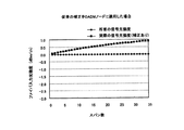
図12は、伝送路上にOADMノードを多段に配置した場合に、ノイズカット比率NCRを導入した補正処理を実施して光強度制御を行ったときの信号光強度と雑音光強度の割合の変化をスパン数に応じて示した一例である。また、図13は、スパン数の増加に対する1チャネルの信号光強度の変化を本発明と従来技術とで比較した一例である。これらの図より、スパン数が増加してもOADMノードから出力されるWDM光の各チャネルの信号光強度は高い精度で一定に制御されることが分かる。したがって、本WDM光伝送システムによれば、伝送路上にOADMノード2Aと光中継ノード2Bが混在していても、各々のノードから出力されるWDM光の各チャネルの信号光強度を高い精度で一定に制御することができ、良好な伝送品質を実現することが可能である。
FIG. 12 shows the change in the ratio between the signal light intensity and the noise light intensity when the light intensity control is performed by performing the correction process introducing the noise cut ratio NCR when the OADM nodes are arranged in multiple stages on the transmission line. It is an example shown according to the number of spans. FIG. 13 is an example in which the change of the signal light intensity of one channel with respect to the increase in the number of spans is compared between the present invention and the prior art. From these figures, it can be seen that even if the number of spans increases, the signal light intensity of each channel of WDM light output from the OADM node is controlled to be constant with high accuracy. Therefore, according to the present WDM optical transmission system, even if the
なお、上述した実施形態では、伝送路上にOADMノードと光中継ノードが混在する一例について説明したが、本発明における伝送路上のノードの種別は上記の一例に限定されるものではない。例えば、WDM光を個々のチャネルに分波した後にチャネル毎に波長分散補償を行い再度各チャネルを合波して伝送路に出力する分散補償ノードが伝送路上に含まれている場合にも本発明は有効である。この場合、分散補償ノードにおけるトータル光強度の制御目標値の補正処理は、上述したOADMノードの場合と同様の処理が実施されることになる。 In the above-described embodiment, an example in which the OADM node and the optical relay node are mixed on the transmission line has been described. However, the type of the node on the transmission line in the present invention is not limited to the above example. For example, the present invention also includes a case where a dispersion compensation node that demultiplexes WDM light into individual channels, performs chromatic dispersion compensation for each channel, multiplexes the channels again, and outputs the resultant to the transmission line is included in the transmission line. Is valid. In this case, the correction processing of the control target value of the total light intensity in the dispersion compensation node is performed in the same manner as in the case of the OADM node described above.
また、上述した実施形態では、ノードの種別に関する情報がシステム管理部から各ノードに伝達される場合を説明したが、各々のノードの補正値算出部に自ノードの種別を予め設定しておくようにしてもよい。ただし、ノード種別がシステム管理部から伝達されるようにしておくことで、システムの立ち上げ後におけるノード機能の追加、変更等に容易に対応することが可能である。 Further, in the above-described embodiment, a case has been described in which information regarding the node type is transmitted from the system management unit to each node, but the type of the own node is set in advance in the correction value calculation unit of each node. It may be. However, by making the node type transmitted from the system management unit, it is possible to easily cope with addition and change of node functions after the system is started up.
以上の各実施形態に関して、さらに以下の付記を開示する。
(付記1) 波長の異なる複数のチャネルを含んだ波長多重(WDM)光が伝送される伝送路と、
前記伝送路上に配置され、前記伝送路から入力されるWDM光を個々のチャネルに分波した後、各チャネルに対して所定の処理を行い、該処理された各チャネルを合波したWDM光を光増幅器で増幅して前記伝送路に出力する少なくとも1つの第1ノードと、
前記伝送路上に配置され、前記伝送路から入力されるWDM光を個々のチャネルに分波することなく光増幅器で増幅して前記伝送路に出力する少なくとも1つの第2ノードと、
を備えたWDM光伝送システムであって、
前記第1ノードおよび前記第2ノードは、それぞれ、自ノード内の前記光増幅器で増幅されたWDM光の強度をモニタする光強度モニタと、該光強度モニタのモニタ結果に応じて、自ノードから前記伝送路に出力するWDM光の1チャネル当たりの信号成分および雑音成分を合わせたトータル光強度が予め設定した制御目標値で一定になるように前記光増幅器の利得を制御する利得制御部と、前記光強度モニタのモニタ結果を基に、WDM光の1チャネルの信号光強度および雑音光強度の割合を求め、1チャネルの信号光強度が全てのノードで一定となるように、前記利得制御部で用いるトータル光強度の制御目標値を補正する補正値算出部と、を有し、さらに、
前記補正値算出部は、自ノードが前記第1ノードおよび前記第2ノードのいずれに該当しているかを判別し、第1ノードに該当しているとき、WDM光を個々のチャネルに分波する際のフィルタリング特性に応じて定めたノイズカット比率を用いた計算式に従って、前記トータル光強度の制御目標値の補正を行うことを特徴とするWDM光伝送システム。
Regarding the above embodiments, the following additional notes are further disclosed.
(Supplementary note 1) A transmission path through which wavelength division multiplexed (WDM) light including a plurality of channels having different wavelengths is transmitted;
WDM light arranged on the transmission path and demultiplexed into WDM light input from the transmission path, each channel is subjected to predetermined processing, and the processed WDM light is multiplexed. At least one first node amplified by an optical amplifier and output to the transmission line;
At least one second node disposed on the transmission line, amplifying the WDM light input from the transmission line by an optical amplifier without demultiplexing the WDM light into individual channels, and outputting the amplified WDM light to the transmission line;
A WDM optical transmission system comprising:
Each of the first node and the second node is an optical intensity monitor that monitors the intensity of the WDM light amplified by the optical amplifier in the own node, and from the own node according to the monitoring result of the optical intensity monitor. A gain controller for controlling the gain of the optical amplifier so that the total light intensity of the signal component and noise component per channel of the WDM light output to the transmission line is constant at a preset control target value; Based on the monitoring result of the light intensity monitor, the ratio of the signal light intensity and noise light intensity of one channel of WDM light is obtained, and the gain control unit is configured so that the signal light intensity of one channel is constant at all nodes. A correction value calculation unit for correcting the control target value of the total light intensity used in
The correction value calculation unit determines whether the own node corresponds to the first node or the second node, and demultiplexes the WDM light into individual channels when corresponding to the first node. A WDM optical transmission system characterized in that the control target value of the total light intensity is corrected according to a calculation formula using a noise cut ratio determined according to the filtering characteristics.
(付記2) 付記1に記載のWDM光伝送システムであって、
前記ノイズカット比率は、個々のチャネルに分波される前のWDM光における1チャネル当たりの雑音成分に対する、個々のチャネルに分波された後の1チャネルに含まれる雑音成分の割合としたことを特徴とするWDM光伝送システム。
(Supplementary note 2) The WDM optical transmission system according to
The noise cut ratio is a ratio of a noise component included in one channel after being demultiplexed into individual channels to a noise component per channel in the WDM light before being demultiplexed into individual channels. A featured WDM optical transmission system.
(付記3) 付記2に記載のWDM光伝送システムであって、
前記ノイズカット比率は、WDM光の隣り合うチャネルの波長間隔に対する、前記フィルタリング特性における各チャネルに対応した透過帯の幅の割合としたことを特徴とするWDM光伝送システム。
(Supplementary note 3) The WDM optical transmission system according to supplementary note 2,
The WDM optical transmission system, wherein the noise cut ratio is a ratio of a width of a transmission band corresponding to each channel in the filtering characteristics to a wavelength interval between adjacent channels of WDM light.
(付記4) 付記1〜3のいずれか1つに記載のWDM光伝送システムであって、
前記第1ノードは、分波した各チャネルに対してアド・ドロップの処理を行うOADMノードであることを特徴とするWDM光伝送システム。
(Supplementary note 4) The WDM optical transmission system according to any one of
The WDM optical transmission system, wherein the first node is an OADM node that performs add / drop processing on each demultiplexed channel.
(付記5) 付記4に記載のWDM光伝送システムであって、
前記OADMノードは、前記伝送路から入力されるWDM光を増幅する入力側の光増幅器と、該入力側の光増幅器で増幅されたWDM光を個々のチャネルに分波してアド・ドロップの処理を行い、該処理された各チャネルを合波して出力するOADMユニットと、該OADMユニットから出力されるWDM光を増幅する第2の光増幅器と、を有し、該第2の光増幅器で増幅されたWDM光の強度が前記光強度モニタでモニタされ、前記利得制御部により前記第2の光増幅器の利得がフィードバック制御されることを特徴とするWDM光伝送システム。
(Additional remark 5) It is a WDM optical transmission system of Additional remark 4, Comprising:
The OADM node includes an optical amplifier on the input side for amplifying the WDM light input from the transmission line, and an add / drop process by demultiplexing the WDM light amplified by the optical amplifier on the input side into individual channels. And an OADM unit that combines and outputs the processed channels, and a second optical amplifier that amplifies the WDM light output from the OADM unit, and the second optical amplifier The intensity of the amplified WDM light is monitored by the optical intensity monitor, and the gain of the second optical amplifier is feedback controlled by the gain control unit.
(付記6) 付記5に記載のWDM光伝送システムであって、
前記OADMユニットは、波長選択スイッチ(WSS)を含むことを特徴とするWDM光伝送システム。
(Supplementary note 6) The WDM optical transmission system according to
The WDM optical transmission system, wherein the OADM unit includes a wavelength selective switch (WSS).
(付記7) 付記5に記載のWDM光伝送システムであって、
前記OADMユニットは、アレイ導波路回折格子(AWG)を含むことを特徴とするWDM光伝送システム。
(Supplementary note 7) The WDM optical transmission system according to
The WDM optical transmission system, wherein the OADM unit includes an arrayed waveguide diffraction grating (AWG).
(付記8) 付記1〜3のいずれか1つに記載のWDM光伝送システムであって、
前記第1ノードは、分波した各チャネルに対して波長分散の補償を行う分散補償ノードであることを特徴とするWDM光伝送システム。
(Supplementary note 8) The WDM optical transmission system according to any one of
The WDM optical transmission system, wherein the first node is a dispersion compensation node that performs chromatic dispersion compensation for each demultiplexed channel.
(付記9) 付記1〜8のいずれか1つに記載のWDM光伝送システムであって、
前記第2ノードは、前記伝送路から入力されるWDM光の各チャネルをインラインアンプにより一括して増幅する光中継ノードであることを特徴とするWDM光伝送システム。
(Supplementary note 9) The WDM optical transmission system according to any one of
The WDM optical transmission system, wherein the second node is an optical repeater node that amplifies each channel of WDM light input from the transmission path in a batch by an in-line amplifier.
(付記10) 付記1〜9のいずれか1つに記載のWDM光伝送システムであって、
前記伝送路上の各ノードに対してシステム管理情報を伝達することにより、各々のノードの動作状態を集中して管理するシステム管理部を備え、
前記補正値算出部は、前記システム管理部から伝達されるノードの種別に関する情報を基に、自ノードが前記第1ノードおよび前記第2ノードのいずれに該当しているかを判別することを特徴とするWDM光伝送システム。
(Supplementary note 10) The WDM optical transmission system according to any one of
By transmitting system management information to each node on the transmission path, the system management unit that centrally manages the operation state of each node,
The correction value calculating unit determines whether the own node corresponds to the first node or the second node based on information on a node type transmitted from the system management unit. WDM optical transmission system.
(付記11) 付記10に記載のWDM光伝送システムであって、
前記光強度モニタは、前記光増幅器で増幅されたWDM光に含まれる全てのチャネルの光強度の総和をモニタし、
前記補正値算出部は、前記光強度モニタのモニタ結果および前記システム管理部から伝達されるWDM光のチャネル数に関する情報を用いて、1チャネル当たりのトータル光強度を算出すると共に、該トータル光強度および前記システム管理部から伝達される光信号対雑音比(OSNR)を用いて、WDM光の1チャネルの信号光強度を算出し、該算出されたトータル光強度および信号光強度、または、OSNRの値を使用して、前記トータル光強度の制御目標値の補正を行うことを特徴とするWDM光伝送システム。
(Supplementary note 11) The WDM optical transmission system according to
The light intensity monitor monitors the total light intensity of all channels included in the WDM light amplified by the optical amplifier,
The correction value calculation unit calculates the total light intensity per channel using the monitoring result of the light intensity monitor and information on the number of channels of WDM light transmitted from the system management unit, and the total light intensity And the signal light intensity of one channel of the WDM light is calculated using the optical signal-to-noise ratio (OSNR) transmitted from the system management unit, and the calculated total light intensity and signal light intensity, or OSNR A WDM optical transmission system, wherein the control target value of the total light intensity is corrected using a value.
(付記12) 付記10に記載のWDM光伝送システムであって、
前記光強度モニタは、前記光増幅器で増幅されたWDM光の1チャネル当たりのトータル光強度、信号光強度および光信号対雑音比(OSNR)をモニタし、
前記補正値算出部は、前記光強度モニタの各モニタ値を使用して、前記トータル光強度の制御目標値の補正を行うことを特徴とするWDM光伝送システム。
(Supplementary note 12) The WDM optical transmission system according to
The light intensity monitor monitors the total light intensity, signal light intensity and optical signal-to-noise ratio (OSNR) per channel of the WDM light amplified by the optical amplifier,
The WDM optical transmission system, wherein the correction value calculation unit corrects the control target value of the total light intensity using each monitor value of the light intensity monitor.
(付記13) 波長の異なる複数のチャネルを含んだ波長多重(WDM)光が伝送される伝送路と、前記伝送路上に配置され、前記伝送路から入力されるWDM光を個々のチャネルに分波した後、各チャネルに対して所定の処理を行い、該処理された各チャネルを合波したWDM光を光増幅器で増幅して前記伝送路に出力する第1ノードと、前記伝送路上に配置され、前記伝送路から入力されるWDM光を個々のチャネルに分波することなく光増幅器で増幅して前記伝送路に出力する第2ノードと、を備えたWDM光伝送システムについて、前記第1および第2の各ノードから前記伝送路に出力されるWDM光の1チャネル当たりの信号成分および雑音成分を合わせたトータル光強度が予め設定した制御目標値で一定になるように、各ノード内の光増幅器の利得を制御する方法であって、
前記第1ノードおよび前記第2ノードにおいて、自ノード内の前記光増幅器で増幅されたWDM光の強度をモニタする過程と、
前記モニタしたWDM光の強度を基に、WDM光の1チャネルの信号光強度および雑音光強度の割合を求め、1チャネルの信号光強度が全てのノードで一定となるように、前記トータル光強度の制御目標値を補正する過程と、
前記モニタしたWDM光の強度に応じて、自ノードから前記伝送路に出力するWDM光の1チャネル当たりのトータル光強度が、前記補正したトータル光強度の制御目標値で一定となるように、自ノード内の前記光増幅器の利得を制御する過程と、を含み、さらに、
前記トータル光強度の制御目標値を補正する過程は、自ノードが前記第1ノードおよび前記第2ノードのいずれに該当しているかを判別し、前記第1ノードに該当しているとき、WDM光を個々のチャネルに分波する際のフィルタリング特性に応じて定めたノイズカット比率を用いた計算式に従って、前記トータル光強度の制御目標値の補正を行うことを特徴とする制御方法。
(Supplementary note 13) A transmission path through which wavelength division multiplexed (WDM) light including a plurality of channels having different wavelengths is transmitted, and a WDM light that is arranged on the transmission path and input from the transmission path is divided into individual channels. Then, a predetermined process is performed on each channel, a WDM light obtained by combining the processed channels is amplified by an optical amplifier and output to the transmission path, and the first node is disposed on the transmission path. A WDM optical transmission system comprising: a second node that amplifies the WDM light input from the transmission path without demultiplexing into individual channels with an optical amplifier and outputs the second node to the transmission path. In each node, the total light intensity including the signal component and noise component per channel of WDM light output from each second node to the transmission path is constant at a preset control target value. A method for controlling the gain of an optical amplifier comprising:
Monitoring the intensity of the WDM light amplified by the optical amplifier in its own node at the first node and the second node;
Based on the intensity of the monitored WDM light, the ratio of the signal light intensity of one channel and the noise light intensity of the WDM light is obtained, and the total light intensity is set so that the signal light intensity of one channel is constant at all nodes. The process of correcting the control target value of
Depending on the intensity of the monitored WDM light, the total light intensity per channel of the WDM light output from the own node to the transmission path is constant at the corrected control target value of the total light intensity. Controlling the gain of the optical amplifier in a node, and
In the process of correcting the control target value of the total light intensity, it is determined whether the own node corresponds to the first node or the second node. The control method is characterized in that the control target value of the total light intensity is corrected according to a calculation formula using a noise cut ratio determined according to a filtering characteristic when demultiplexing into individual channels.
1 伝送路
2A OADMノード
2B 光中継ノード
3 システム管理部
4 記憶部
11 入力ポート
12 出力ポート
13,15 光増幅器
14 OADMユニット
14A,14J,16 光分岐器
14B,14C,14D,14E 波長選択スイッチ(WSS)
14F,14G,14H,14I アレイ導波路回折格子(AWG)
14K 2×1光スイッチ
17 光強度モニタ
17A フォトディテクタ
17B 光パワーメータ
17C 光スペクトルアナライザ
17D チャネルモニタ
18 補正値算出部
19 利得制御部
S チャネル間隔
Wfil フィルタ帯域幅
DESCRIPTION OF
14F, 14G, 14H, 14I Arrayed waveguide diffraction grating (AWG)
14K 2 × 1
Claims (7)
前記伝送路上に配置され、前記伝送路から入力されるWDM光を個々のチャネルに分波した後、該分波された各チャネルに対して波長分散の補償を行い、該波長分散補償された各チャネルを合波したWDM光を光増幅器で増幅して前記伝送路に出力する少なくとも1つの第1ノードと、
前記伝送路上に配置され、前記伝送路から入力されるWDM光を個々のチャネルに分波することなく光増幅器で増幅して前記伝送路に出力する少なくとも1つの第2ノードと、
を備えたWDM光伝送システムであって、
前記第1ノードおよび前記第2ノードは、それぞれ、自ノード内の前記光増幅器で増幅されたWDM光の強度をモニタする光強度モニタと、該光強度モニタのモニタ結果に応じて、自ノードから前記伝送路に出力するWDM光の1チャネル当たりの信号成分および雑音成分を合わせたトータル光強度が予め設定した制御目標値で一定になるように前記光増幅器の利得を制御する利得制御部と、前記光強度モニタのモニタ結果を基に、WDM光の1チャネルの信号光強度および雑音光強度の割合を求め、1チャネルの信号光強度が全てのノードで一定となるように、前記利得制御部で用いるトータル光強度の制御目標値を補正する補正値算出部と、前記伝送路上の各ノードに対してノードの種別に関する情報を含むシステム管理情報を伝達することにより、各々のノードの動作状態を集中して管理するシステム管理部と、を有し、さらに、
前記補正値算出部は、前記システム管理部から伝達されるノードの種別に関する情報を基に、自ノードが前記第1ノードおよび前記第2ノードのいずれに該当しているかを判別し、第1ノードに該当しているとき、WDM光を個々のチャネルに分波する際のフィルタリング特性に応じて定めたノイズカット比率を用いた計算式に従って、前記トータル光強度の制御目標値の補正を行うことを特徴とするWDM光伝送システム。 A transmission line through which wavelength division multiplexed (WDM) light including a plurality of channels having different wavelengths is transmitted;
After demultiplexing the WDM light that is arranged on the transmission path and input from the transmission path into individual channels, chromatic dispersion is compensated for each demultiplexed channel, and each chromatic dispersion compensated At least one first node that amplifies the WDM light combined with the channel by an optical amplifier and outputs the amplified WDM light to the transmission line;
At least one second node disposed on the transmission line, amplifying the WDM light input from the transmission line by an optical amplifier without demultiplexing the WDM light into individual channels, and outputting the amplified WDM light to the transmission line;
A WDM optical transmission system comprising:
Each of the first node and the second node is an optical intensity monitor that monitors the intensity of the WDM light amplified by the optical amplifier in the own node, and from the own node according to the monitoring result of the optical intensity monitor. A gain controller for controlling the gain of the optical amplifier so that the total light intensity of the signal component and noise component per channel of the WDM light output to the transmission line is constant at a preset control target value; Based on the monitoring result of the light intensity monitor, the ratio of the signal light intensity and noise light intensity of one channel of WDM light is obtained, and the gain control unit is configured so that the signal light intensity of one channel is constant at all nodes. transmitting a correction value calculating unit for correcting the control target value of the total light intensity, the system management information including information related to the type of the node for each node of the transmission path to be used in And by having a system management section for managing concentrating the operating state of each node, and further,
The correction value calculation unit determines whether the own node corresponds to the first node or the second node based on the information regarding the type of node transmitted from the system management unit. The control target value of the total light intensity is corrected according to a calculation formula using a noise cut ratio determined according to a filtering characteristic when demultiplexing WDM light into individual channels. A featured WDM optical transmission system.
前記ノイズカット比率は、個々のチャネルに分波される前のWDM光における1チャネル当たりの雑音成分に対する、個々のチャネルに分波された後の1チャネルに含まれる雑音成分の割合としたことを特徴とするWDM光伝送システム。 The WDM optical transmission system according to claim 1,
The noise cut ratio is a ratio of a noise component included in one channel after being demultiplexed into individual channels to a noise component per channel in the WDM light before being demultiplexed into individual channels. A featured WDM optical transmission system.
前記ノイズカット比率は、WDM光の隣り合うチャネルの波長間隔に対する、前記フィルタリング特性における各チャネルに対応した透過帯の幅の割合としたことを特徴とするWDM光伝送システム。 The WDM optical transmission system according to claim 2,
The WDM optical transmission system, wherein the noise cut ratio is a ratio of a width of a transmission band corresponding to each channel in the filtering characteristics to a wavelength interval between adjacent channels of WDM light.
前記第2ノードは、前記伝送路から入力されるWDM光の各チャネルをインラインアンプにより一括して増幅する光中継ノードであることを特徴とするWDM光伝送システム。 The WDM optical transmission system according to any one of claims 1 to 3,
The WDM optical transmission system, wherein the second node is an optical repeater node that amplifies each channel of WDM light input from the transmission path in a batch by an in-line amplifier .
前記光強度モニタは、前記光増幅器で増幅されたWDM光に含まれる全てのチャネルの光強度の総和をモニタし、
前記補正値算出部は、前記光強度モニタのモニタ結果および前記システム管理部から伝達されるWDM光のチャネル数に関する情報を用いて、1チャネル当たりのトータル光強度を算出すると共に、該トータル光強度および前記システム管理部から伝達される光信号対雑音比(OSNR)を用いて、WDM光の1チャネルの信号光強度を算出し、該算出されたトータル光強度および信号光強度、または、OSNRの値を使用して、前記トータル光強度の制御目標値の補正を行うことを特徴とするWDM光伝送システム。 The WDM optical transmission system according to any one of claims 1 to 4 ,
The light intensity monitor monitors the total light intensity of all channels included in the WDM light amplified by the optical amplifier,
The correction value calculation unit calculates the total light intensity per channel using the monitoring result of the light intensity monitor and information on the number of channels of WDM light transmitted from the system management unit, and the total light intensity And the signal light intensity of one channel of the WDM light is calculated using the optical signal-to-noise ratio (OSNR) transmitted from the system management unit, and the calculated total light intensity and signal light intensity, or OSNR A WDM optical transmission system, wherein the control target value of the total light intensity is corrected using a value.
前記光強度モニタは、前記光増幅器で増幅されたWDM光の1チャネル当たりのトータル光強度、信号光強度および光信号対雑音比(OSNR)をモニタし、
前記補正値算出部は、前記光強度モニタの各モニタ値を使用して、前記トータル光強度の制御目標値の補正を行うことを特徴とするWDM光伝送システム。 The WDM optical transmission system according to any one of claims 1 to 4 ,
The light intensity monitor monitors the total light intensity, signal light intensity and optical signal-to-noise ratio (OSNR) per channel of the WDM light amplified by the optical amplifier,
The WDM optical transmission system, wherein the correction value calculation unit corrects the control target value of the total light intensity using each monitor value of the light intensity monitor.
前記第1ノードおよび前記第2ノードにおいて、自ノード内の前記光増幅器で増幅されたWDM光の強度をモニタする過程と、
前記モニタしたWDM光の強度を基に、WDM光の1チャネルの信号光強度および雑音光強度の割合を求め、1チャネルの信号光強度が全てのノードで一定となるように、前記トータル光強度の制御目標値を補正する過程と、
前記モニタしたWDM光の強度に応じて、自ノードから前記伝送路に出力するWDM光の1チャネル当たりのトータル光強度が、前記補正したトータル光強度の制御目標値で一定となるように、自ノード内の前記光増幅器の利得を制御する過程と、
前記伝送路上の各ノードに対してノードの種別に関する情報を含むシステム管理情報をを伝達する過程と、を含み、さらに、
前記トータル光強度の制御目標値を補正する過程は、前記伝達されるノードの種別に関する情報を基に、自ノードが前記第1ノードおよび前記第2ノードのいずれに該当しているかを判別し、前記第1ノードに該当しているとき、WDM光を個々のチャネルに分波する際のフィルタリング特性に応じて定めたノイズカット比率を用いた計算式に従って、前記トータル光強度の制御目標値の補正を行うことを特徴とする制御方法。 A transmission path through which wavelength division multiplexed (WDM) light including a plurality of channels having different wavelengths is transmitted; and after demultiplexing the WDM light input from the transmission path into individual channels, A first node that compensates chromatic dispersion for each demultiplexed channel, amplifies the WDM light obtained by multiplexing the chromatic dispersion compensated channels with an optical amplifier, and outputs the amplified WDM light to the transmission line; and A WDM optical transmission system comprising: a second node arranged on a path and amplifying the WDM light input from the transmission path by an optical amplifier without being demultiplexed into individual channels and outputting the amplified signal to the transmission path. The total light intensity including the signal component and noise component per channel of the WDM light output from the first and second nodes to the transmission path is constant at a preset control target value. A method for controlling the gain of the optical amplifier in each node,
Monitoring the intensity of the WDM light amplified by the optical amplifier in its own node at the first node and the second node;
Based on the intensity of the monitored WDM light, the ratio of the signal light intensity of one channel and the noise light intensity of the WDM light is obtained, and the total light intensity is set so that the signal light intensity of one channel is constant at all nodes. The process of correcting the control target value of
Depending on the intensity of the monitored WDM light, the total light intensity per channel of the WDM light output from the own node to the transmission path is constant at the corrected control target value of the total light intensity. Controlling the gain of the optical amplifier in a node;
Transmitting system management information including information related to the type of node to each node on the transmission path , and
In the process of correcting the control target value of the total light intensity, it is determined whether the own node corresponds to the first node or the second node based on the information on the type of the transmitted node . When corresponding to the first node, the control target value of the total light intensity is corrected according to a calculation formula using a noise cut ratio determined according to a filtering characteristic when demultiplexing WDM light into individual channels. The control method characterized by performing.
Priority Applications (2)
| Application Number | Priority Date | Filing Date | Title |
|---|---|---|---|
| JP2008197392A JP5347363B2 (en) | 2008-07-31 | 2008-07-31 | WDM optical transmission system and control method thereof |
| US12/453,063 US8086106B2 (en) | 2008-07-31 | 2009-04-28 | WDM optical transmission system and controlling method thereof |
Applications Claiming Priority (1)
| Application Number | Priority Date | Filing Date | Title |
|---|---|---|---|
| JP2008197392A JP5347363B2 (en) | 2008-07-31 | 2008-07-31 | WDM optical transmission system and control method thereof |
Publications (2)
| Publication Number | Publication Date |
|---|---|
| JP2010035089A JP2010035089A (en) | 2010-02-12 |
| JP5347363B2 true JP5347363B2 (en) | 2013-11-20 |
Family
ID=41608482
Family Applications (1)
| Application Number | Title | Priority Date | Filing Date |
|---|---|---|---|
| JP2008197392A Expired - Fee Related JP5347363B2 (en) | 2008-07-31 | 2008-07-31 | WDM optical transmission system and control method thereof |
Country Status (2)
| Country | Link |
|---|---|
| US (1) | US8086106B2 (en) |
| JP (1) | JP5347363B2 (en) |
Families Citing this family (9)
| Publication number | Priority date | Publication date | Assignee | Title |
|---|---|---|---|---|
| JP5525041B2 (en) * | 2009-05-14 | 2014-06-18 | タイコ エレクトロニクス サブシー コミュニケーションズ エルエルシー | Branch arrangement including a separate branch unit and a predetermined wavelength filter unit, and system and method including the same |
| JP5633266B2 (en) * | 2010-09-15 | 2014-12-03 | 富士通株式会社 | WDM optical transmission system and control method thereof |
| JP5772107B2 (en) * | 2011-03-17 | 2015-09-02 | 富士通株式会社 | Wavelength selective switch and optical transmission device |
| JP5899849B2 (en) * | 2011-11-16 | 2016-04-06 | 富士通株式会社 | Optical transmission system, optical transmission apparatus, signal adjustment program, and signal adjustment method |
| US8989197B2 (en) * | 2012-04-02 | 2015-03-24 | Nec Laboratories America, Inc. | Reconfigurable branching unit for submarine optical communication networks |
| CN108269886B (en) * | 2016-12-30 | 2019-12-10 | Tcl集团股份有限公司 | Quantum dot material, preparation method and semiconductor device |
| CN108264900A (en) * | 2016-12-30 | 2018-07-10 | Tcl集团股份有限公司 | A kind of quantum dot composite material, preparation method and semiconductor devices |
| US10182357B1 (en) * | 2017-09-20 | 2019-01-15 | Echelon Corporation | System and method for bottom-up invocation of control signal repeaters in a mesh lighting network |
| US10419953B2 (en) * | 2017-12-05 | 2019-09-17 | Echelon Corporation | Self-healing lighting network |
Family Cites Families (18)
| Publication number | Priority date | Publication date | Assignee | Title |
|---|---|---|---|---|
| JP3396270B2 (en) * | 1993-08-10 | 2003-04-14 | 富士通株式会社 | Optical dispersion compensation method |
| JPH10276172A (en) * | 1997-03-28 | 1998-10-13 | Kokusai Denshin Denwa Co Ltd <Kdd> | Wavelength division optical processor and optical communication transmission line using the same |
| JP4498509B2 (en) * | 1999-11-16 | 2010-07-07 | 富士通株式会社 | Control device and control method of wavelength division multiplexing optical amplifier |
| JP3576440B2 (en) * | 2000-01-05 | 2004-10-13 | 日本電信電話株式会社 | Optical amplifier, node device, and optical communication network system |
| JP4689015B2 (en) * | 2000-08-14 | 2011-05-25 | 富士通株式会社 | Optical amplification device, optical amplification method, and optical communication system |
| JP4565794B2 (en) | 2000-09-07 | 2010-10-20 | 富士通株式会社 | Optical amplification device and optical communication system |
| JP4588234B2 (en) * | 2001-03-15 | 2010-11-24 | 富士通株式会社 | Optical device and wavelength division multiplexing communication system using the same |
| US6600596B2 (en) * | 2001-05-09 | 2003-07-29 | Ciena Corporation | Method and system for controlling amplifier power in an optical communications network having add/drop capability |
| JP4000251B2 (en) * | 2001-10-31 | 2007-10-31 | 富士通株式会社 | Optical signal switching device and control method thereof |
| JP4769443B2 (en) * | 2004-09-16 | 2011-09-07 | 富士通株式会社 | Control device and control method for optical amplification device |
| JP4929664B2 (en) * | 2005-03-14 | 2012-05-09 | 富士通株式会社 | Optical amplifier control device, optical amplifier control method, optical transmission device, optical amplifier, optical amplifier using band-unit gain equalizer, and wavelength division multiplexing transmission system using band-unit gain equalizer |
| JP4727485B2 (en) * | 2006-03-31 | 2011-07-20 | 富士通株式会社 | Optical transmission equipment |
| JP4822931B2 (en) * | 2006-05-19 | 2011-11-24 | 富士通株式会社 | Wavelength division multiplexing optical transmission system and management method thereof |
| JP4940861B2 (en) * | 2006-09-28 | 2012-05-30 | 富士通株式会社 | WDM optical transmission system |
| JP5135849B2 (en) * | 2007-03-30 | 2013-02-06 | 富士通株式会社 | Gain control device, optical transmission device, and gain control method for optical amplifier |
| US7969647B2 (en) * | 2007-10-08 | 2011-06-28 | Jds Uniphase Corporation | Apparatus and method for flattening gain profile of an optical amplifier |
| JP5428278B2 (en) * | 2008-10-14 | 2014-02-26 | 富士通株式会社 | Optical amplifier control device |
| JP5321041B2 (en) * | 2008-12-24 | 2013-10-23 | 富士通株式会社 | Optical add / drop multiplexer and WDM transmission method |
-
2008
- 2008-07-31 JP JP2008197392A patent/JP5347363B2/en not_active Expired - Fee Related
-
2009
- 2009-04-28 US US12/453,063 patent/US8086106B2/en not_active Expired - Fee Related
Also Published As
| Publication number | Publication date |
|---|---|
| US20100028003A1 (en) | 2010-02-04 |
| US8086106B2 (en) | 2011-12-27 |
| JP2010035089A (en) | 2010-02-12 |
Similar Documents
| Publication | Publication Date | Title |
|---|---|---|
| JP5347363B2 (en) | WDM optical transmission system and control method thereof | |
| JP3995781B2 (en) | Optical branching / inserting device and optical branching device using wavelength selective filter | |
| JP5633266B2 (en) | WDM optical transmission system and control method thereof | |
| JP4941349B2 (en) | Optical transmission device used in PON system | |
| EP1622297B1 (en) | Optical add/drop multiplexer | |
| US10608775B2 (en) | Optical transmission apparatus, optical transmission method, and optical transmission system | |
| EP2355388A2 (en) | Optical network and control method therefor | |
| US20030058497A1 (en) | All-optical switching sites for an agile optical network | |
| JP2010154104A (en) | Wdm transmission apparatus, optical add-drop multiplexer, and wdm transmission method | |
| JPH11331127A (en) | Wavelength division multiplex system and terminal station thereof | |
| JP2001144692A (en) | Device and method for controlling wavelength multiplex optical amplifier | |
| JP2012169870A (en) | Optical transmission device and optical filter circuit | |
| JP2008503886A (en) | Wavelength division multiplexing (WDM) optical demultiplexer | |
| JP2019075654A (en) | Transmission system and transmission method | |
| JP2001024262A (en) | Wavelength gain characteristics shift filter, optical transmitter and optical transmission method | |
| JP4915449B2 (en) | Optical transmission equipment | |
| US7130542B2 (en) | Modular multiplexing/demultiplexing units in optical transmission systems | |
| EP3767843A1 (en) | Variable equalizer and method for controlling variable equalizer | |
| JP3482962B2 (en) | Optical amplifier and optical transmission system using the same | |
| JP2002208893A (en) | Optical filter and wavelength multiplex optical transmission system using the same | |
| JP2000004061A (en) | Optical gain equalization device | |
| KR100312375B1 (en) | Wavelength Division Branch Multiplexer | |
| US11184102B2 (en) | Apparatus and adding and dropping method | |
| JP5994855B2 (en) | Wavelength division multiplexing optical transmission equipment | |
| JP2000165353A (en) | Wavelength multiplex optical transmitter and wavelength multiplex optical transmission equipment provided with the same |
Legal Events
| Date | Code | Title | Description |
|---|---|---|---|
| A621 | Written request for application examination |
Free format text: JAPANESE INTERMEDIATE CODE: A621 Effective date: 20110418 |
|
| A977 | Report on retrieval |
Free format text: JAPANESE INTERMEDIATE CODE: A971007 Effective date: 20120911 |
|
| A131 | Notification of reasons for refusal |
Free format text: JAPANESE INTERMEDIATE CODE: A131 Effective date: 20120918 |
|
| A521 | Request for written amendment filed |
Free format text: JAPANESE INTERMEDIATE CODE: A523 Effective date: 20121112 |
|
| RD02 | Notification of acceptance of power of attorney |
Free format text: JAPANESE INTERMEDIATE CODE: A7422 Effective date: 20121129 |
|
| RD04 | Notification of resignation of power of attorney |
Free format text: JAPANESE INTERMEDIATE CODE: A7424 Effective date: 20121130 |
|
| A131 | Notification of reasons for refusal |
Free format text: JAPANESE INTERMEDIATE CODE: A131 Effective date: 20130226 |
|
| A521 | Request for written amendment filed |
Free format text: JAPANESE INTERMEDIATE CODE: A523 Effective date: 20130422 |
|
| TRDD | Decision of grant or rejection written | ||
| A01 | Written decision to grant a patent or to grant a registration (utility model) |
Free format text: JAPANESE INTERMEDIATE CODE: A01 Effective date: 20130723 |
|
| A61 | First payment of annual fees (during grant procedure) |
Free format text: JAPANESE INTERMEDIATE CODE: A61 Effective date: 20130805 |
|
| R150 | Certificate of patent or registration of utility model |
Free format text: JAPANESE INTERMEDIATE CODE: R150 |
|
| LAPS | Cancellation because of no payment of annual fees |