JP5341180B2 - Transmit power control for wireless charging system - Google Patents
Transmit power control for wireless charging system Download PDFInfo
- Publication number
- JP5341180B2 JP5341180B2 JP2011509596A JP2011509596A JP5341180B2 JP 5341180 B2 JP5341180 B2 JP 5341180B2 JP 2011509596 A JP2011509596 A JP 2011509596A JP 2011509596 A JP2011509596 A JP 2011509596A JP 5341180 B2 JP5341180 B2 JP 5341180B2
- Authority
- JP
- Japan
- Prior art keywords
- power
- receiver
- antenna
- control signal
- electromagnetic field
- Prior art date
- Legal status (The legal status is an assumption and is not a legal conclusion. Google has not performed a legal analysis and makes no representation as to the accuracy of the status listed.)
- Expired - Fee Related
Links
- 238000012546 transfer Methods 0.000 claims abstract description 28
- 230000004044 response Effects 0.000 claims description 51
- 230000005540 biological transmission Effects 0.000 claims description 49
- 230000005672 electromagnetic field Effects 0.000 claims description 36
- 238000004891 communication Methods 0.000 claims description 29
- 238000000034 method Methods 0.000 claims description 18
- 230000008859 change Effects 0.000 claims description 8
- 230000007423 decrease Effects 0.000 claims description 2
- 230000005855 radiation Effects 0.000 abstract description 8
- 230000001105 regulatory effect Effects 0.000 abstract 2
- 230000008878 coupling Effects 0.000 description 50
- 238000010168 coupling process Methods 0.000 description 50
- 238000005859 coupling reaction Methods 0.000 description 50
- 238000010586 diagram Methods 0.000 description 30
- 230000002441 reversible effect Effects 0.000 description 28
- 230000011664 signaling Effects 0.000 description 24
- 239000003990 capacitor Substances 0.000 description 15
- 238000004088 simulation Methods 0.000 description 9
- 230000000670 limiting effect Effects 0.000 description 8
- 238000013459 approach Methods 0.000 description 5
- 238000006243 chemical reaction Methods 0.000 description 5
- 238000005516 engineering process Methods 0.000 description 4
- 238000001514 detection method Methods 0.000 description 3
- 230000006870 function Effects 0.000 description 3
- 230000007246 mechanism Effects 0.000 description 3
- 230000003287 optical effect Effects 0.000 description 3
- 230000010355 oscillation Effects 0.000 description 3
- 230000003044 adaptive effect Effects 0.000 description 2
- 230000003247 decreasing effect Effects 0.000 description 2
- 239000000835 fiber Substances 0.000 description 2
- 230000008569 process Effects 0.000 description 2
- 230000002829 reductive effect Effects 0.000 description 2
- 238000004804 winding Methods 0.000 description 2
- 230000003321 amplification Effects 0.000 description 1
- 230000001413 cellular effect Effects 0.000 description 1
- 238000004590 computer program Methods 0.000 description 1
- 239000004020 conductor Substances 0.000 description 1
- 125000004122 cyclic group Chemical group 0.000 description 1
- 238000013461 design Methods 0.000 description 1
- 230000005684 electric field Effects 0.000 description 1
- 238000001914 filtration Methods 0.000 description 1
- 230000001939 inductive effect Effects 0.000 description 1
- 239000006249 magnetic particle Substances 0.000 description 1
- 239000002184 metal Substances 0.000 description 1
- 238000012986 modification Methods 0.000 description 1
- 230000004048 modification Effects 0.000 description 1
- 230000005404 monopole Effects 0.000 description 1
- 238000003199 nucleic acid amplification method Methods 0.000 description 1
- 230000036961 partial effect Effects 0.000 description 1
- 239000002245 particle Substances 0.000 description 1
- 230000002093 peripheral effect Effects 0.000 description 1
- 230000000644 propagated effect Effects 0.000 description 1
- 230000001902 propagating effect Effects 0.000 description 1
- 229910000859 α-Fe Inorganic materials 0.000 description 1
Images


Classifications
-
- G—PHYSICS
- G06—COMPUTING; CALCULATING OR COUNTING
- G06K—GRAPHICAL DATA READING; PRESENTATION OF DATA; RECORD CARRIERS; HANDLING RECORD CARRIERS
- G06K7/00—Methods or arrangements for sensing record carriers, e.g. for reading patterns
- G06K7/0008—General problems related to the reading of electronic memory record carriers, independent of its reading method, e.g. power transfer
-
- G—PHYSICS
- G06—COMPUTING; CALCULATING OR COUNTING
- G06K—GRAPHICAL DATA READING; PRESENTATION OF DATA; RECORD CARRIERS; HANDLING RECORD CARRIERS
- G06K19/00—Record carriers for use with machines and with at least a part designed to carry digital markings
- G06K19/06—Record carriers for use with machines and with at least a part designed to carry digital markings characterised by the kind of the digital marking, e.g. shape, nature, code
- G06K19/067—Record carriers with conductive marks, printed circuits or semiconductor circuit elements, e.g. credit or identity cards also with resonating or responding marks without active components
- G06K19/07—Record carriers with conductive marks, printed circuits or semiconductor circuit elements, e.g. credit or identity cards also with resonating or responding marks without active components with integrated circuit chips
- G06K19/0701—Record carriers with conductive marks, printed circuits or semiconductor circuit elements, e.g. credit or identity cards also with resonating or responding marks without active components with integrated circuit chips at least one of the integrated circuit chips comprising an arrangement for power management
- G06K19/0715—Record carriers with conductive marks, printed circuits or semiconductor circuit elements, e.g. credit or identity cards also with resonating or responding marks without active components with integrated circuit chips at least one of the integrated circuit chips comprising an arrangement for power management the arrangement including means to regulate power transfer to the integrated circuit
-
- G—PHYSICS
- G06—COMPUTING; CALCULATING OR COUNTING
- G06K—GRAPHICAL DATA READING; PRESENTATION OF DATA; RECORD CARRIERS; HANDLING RECORD CARRIERS
- G06K19/00—Record carriers for use with machines and with at least a part designed to carry digital markings
- G06K19/06—Record carriers for use with machines and with at least a part designed to carry digital markings characterised by the kind of the digital marking, e.g. shape, nature, code
- G06K19/067—Record carriers with conductive marks, printed circuits or semiconductor circuit elements, e.g. credit or identity cards also with resonating or responding marks without active components
- G06K19/07—Record carriers with conductive marks, printed circuits or semiconductor circuit elements, e.g. credit or identity cards also with resonating or responding marks without active components with integrated circuit chips
- G06K19/0723—Record carriers with conductive marks, printed circuits or semiconductor circuit elements, e.g. credit or identity cards also with resonating or responding marks without active components with integrated circuit chips the record carrier comprising an arrangement for non-contact communication, e.g. wireless communication circuits on transponder cards, non-contact smart cards or RFIDs
-
- G—PHYSICS
- G06—COMPUTING; CALCULATING OR COUNTING
- G06K—GRAPHICAL DATA READING; PRESENTATION OF DATA; RECORD CARRIERS; HANDLING RECORD CARRIERS
- G06K7/00—Methods or arrangements for sensing record carriers, e.g. for reading patterns
- G06K7/10—Methods or arrangements for sensing record carriers, e.g. for reading patterns by electromagnetic radiation, e.g. optical sensing; by corpuscular radiation
- G06K7/10009—Methods or arrangements for sensing record carriers, e.g. for reading patterns by electromagnetic radiation, e.g. optical sensing; by corpuscular radiation sensing by radiation using wavelengths larger than 0.1 mm, e.g. radio-waves or microwaves
- G06K7/10158—Methods or arrangements for sensing record carriers, e.g. for reading patterns by electromagnetic radiation, e.g. optical sensing; by corpuscular radiation sensing by radiation using wavelengths larger than 0.1 mm, e.g. radio-waves or microwaves methods and means used by the interrogation device for reliably powering the wireless record carriers using an electromagnetic interrogation field
- G06K7/10178—Methods or arrangements for sensing record carriers, e.g. for reading patterns by electromagnetic radiation, e.g. optical sensing; by corpuscular radiation sensing by radiation using wavelengths larger than 0.1 mm, e.g. radio-waves or microwaves methods and means used by the interrogation device for reliably powering the wireless record carriers using an electromagnetic interrogation field including auxiliary means for focusing, repeating or boosting the electromagnetic interrogation field
-
- H—ELECTRICITY
- H01—ELECTRIC ELEMENTS
- H01F—MAGNETS; INDUCTANCES; TRANSFORMERS; SELECTION OF MATERIALS FOR THEIR MAGNETIC PROPERTIES
- H01F38/00—Adaptations of transformers or inductances for specific applications or functions
- H01F38/14—Inductive couplings
-
- H—ELECTRICITY
- H01—ELECTRIC ELEMENTS
- H01Q—ANTENNAS, i.e. RADIO AERIALS
- H01Q1/00—Details of, or arrangements associated with, antennas
- H01Q1/12—Supports; Mounting means
- H01Q1/22—Supports; Mounting means by structural association with other equipment or articles
- H01Q1/2208—Supports; Mounting means by structural association with other equipment or articles associated with components used in interrogation type services, i.e. in systems for information exchange between an interrogator/reader and a tag/transponder, e.g. in Radio Frequency Identification [RFID] systems
- H01Q1/2225—Supports; Mounting means by structural association with other equipment or articles associated with components used in interrogation type services, i.e. in systems for information exchange between an interrogator/reader and a tag/transponder, e.g. in Radio Frequency Identification [RFID] systems used in active tags, i.e. provided with its own power source or in passive tags, i.e. deriving power from RF signal
-
- H—ELECTRICITY
- H01—ELECTRIC ELEMENTS
- H01Q—ANTENNAS, i.e. RADIO AERIALS
- H01Q1/00—Details of, or arrangements associated with, antennas
- H01Q1/36—Structural form of radiating elements, e.g. cone, spiral, umbrella; Particular materials used therewith
- H01Q1/38—Structural form of radiating elements, e.g. cone, spiral, umbrella; Particular materials used therewith formed by a conductive layer on an insulating support
-
- H—ELECTRICITY
- H01—ELECTRIC ELEMENTS
- H01Q—ANTENNAS, i.e. RADIO AERIALS
- H01Q7/00—Loop antennas with a substantially uniform current distribution around the loop and having a directional radiation pattern in a plane perpendicular to the plane of the loop
-
- H02J5/005—
-
- H—ELECTRICITY
- H02—GENERATION; CONVERSION OR DISTRIBUTION OF ELECTRIC POWER
- H02J—CIRCUIT ARRANGEMENTS OR SYSTEMS FOR SUPPLYING OR DISTRIBUTING ELECTRIC POWER; SYSTEMS FOR STORING ELECTRIC ENERGY
- H02J50/00—Circuit arrangements or systems for wireless supply or distribution of electric power
- H02J50/005—Mechanical details of housing or structure aiming to accommodate the power transfer means, e.g. mechanical integration of coils, antennas or transducers into emitting or receiving devices
-
- H—ELECTRICITY
- H02—GENERATION; CONVERSION OR DISTRIBUTION OF ELECTRIC POWER
- H02J—CIRCUIT ARRANGEMENTS OR SYSTEMS FOR SUPPLYING OR DISTRIBUTING ELECTRIC POWER; SYSTEMS FOR STORING ELECTRIC ENERGY
- H02J50/00—Circuit arrangements or systems for wireless supply or distribution of electric power
- H02J50/10—Circuit arrangements or systems for wireless supply or distribution of electric power using inductive coupling
- H02J50/12—Circuit arrangements or systems for wireless supply or distribution of electric power using inductive coupling of the resonant type
-
- H—ELECTRICITY
- H02—GENERATION; CONVERSION OR DISTRIBUTION OF ELECTRIC POWER
- H02J—CIRCUIT ARRANGEMENTS OR SYSTEMS FOR SUPPLYING OR DISTRIBUTING ELECTRIC POWER; SYSTEMS FOR STORING ELECTRIC ENERGY
- H02J50/00—Circuit arrangements or systems for wireless supply or distribution of electric power
- H02J50/20—Circuit arrangements or systems for wireless supply or distribution of electric power using microwaves or radio frequency waves
-
- H—ELECTRICITY
- H02—GENERATION; CONVERSION OR DISTRIBUTION OF ELECTRIC POWER
- H02J—CIRCUIT ARRANGEMENTS OR SYSTEMS FOR SUPPLYING OR DISTRIBUTING ELECTRIC POWER; SYSTEMS FOR STORING ELECTRIC ENERGY
- H02J50/00—Circuit arrangements or systems for wireless supply or distribution of electric power
- H02J50/40—Circuit arrangements or systems for wireless supply or distribution of electric power using two or more transmitting or receiving devices
-
- H—ELECTRICITY
- H02—GENERATION; CONVERSION OR DISTRIBUTION OF ELECTRIC POWER
- H02J—CIRCUIT ARRANGEMENTS OR SYSTEMS FOR SUPPLYING OR DISTRIBUTING ELECTRIC POWER; SYSTEMS FOR STORING ELECTRIC ENERGY
- H02J50/00—Circuit arrangements or systems for wireless supply or distribution of electric power
- H02J50/50—Circuit arrangements or systems for wireless supply or distribution of electric power using additional energy repeaters between transmitting devices and receiving devices
-
- H—ELECTRICITY
- H02—GENERATION; CONVERSION OR DISTRIBUTION OF ELECTRIC POWER
- H02J—CIRCUIT ARRANGEMENTS OR SYSTEMS FOR SUPPLYING OR DISTRIBUTING ELECTRIC POWER; SYSTEMS FOR STORING ELECTRIC ENERGY
- H02J50/00—Circuit arrangements or systems for wireless supply or distribution of electric power
- H02J50/80—Circuit arrangements or systems for wireless supply or distribution of electric power involving the exchange of data, concerning supply or distribution of electric power, between transmitting devices and receiving devices
-
- H—ELECTRICITY
- H02—GENERATION; CONVERSION OR DISTRIBUTION OF ELECTRIC POWER
- H02J—CIRCUIT ARRANGEMENTS OR SYSTEMS FOR SUPPLYING OR DISTRIBUTING ELECTRIC POWER; SYSTEMS FOR STORING ELECTRIC ENERGY
- H02J50/00—Circuit arrangements or systems for wireless supply or distribution of electric power
- H02J50/90—Circuit arrangements or systems for wireless supply or distribution of electric power involving detection or optimisation of position, e.g. alignment
-
- H02J7/025—
-
- H04B5/48—
-
- H04B5/72—
-
- H04B5/79—
-
- H—ELECTRICITY
- H02—GENERATION; CONVERSION OR DISTRIBUTION OF ELECTRIC POWER
- H02J—CIRCUIT ARRANGEMENTS OR SYSTEMS FOR SUPPLYING OR DISTRIBUTING ELECTRIC POWER; SYSTEMS FOR STORING ELECTRIC ENERGY
- H02J50/00—Circuit arrangements or systems for wireless supply or distribution of electric power
- H02J50/50—Circuit arrangements or systems for wireless supply or distribution of electric power using additional energy repeaters between transmitting devices and receiving devices
- H02J50/502—Circuit arrangements or systems for wireless supply or distribution of electric power using additional energy repeaters between transmitting devices and receiving devices the energy repeater being integrated together with the emitter or the receiver
-
- H—ELECTRICITY
- H02—GENERATION; CONVERSION OR DISTRIBUTION OF ELECTRIC POWER
- H02J—CIRCUIT ARRANGEMENTS OR SYSTEMS FOR SUPPLYING OR DISTRIBUTING ELECTRIC POWER; SYSTEMS FOR STORING ELECTRIC ENERGY
- H02J50/00—Circuit arrangements or systems for wireless supply or distribution of electric power
- H02J50/60—Circuit arrangements or systems for wireless supply or distribution of electric power responsive to the presence of foreign objects, e.g. detection of living beings
-
- H—ELECTRICITY
- H02—GENERATION; CONVERSION OR DISTRIBUTION OF ELECTRIC POWER
- H02J—CIRCUIT ARRANGEMENTS OR SYSTEMS FOR SUPPLYING OR DISTRIBUTING ELECTRIC POWER; SYSTEMS FOR STORING ELECTRIC ENERGY
- H02J7/00—Circuit arrangements for charging or depolarising batteries or for supplying loads from batteries
- H02J7/00032—Circuit arrangements for charging or depolarising batteries or for supplying loads from batteries characterised by data exchange
- H02J7/00034—Charger exchanging data with an electronic device, i.e. telephone, whose internal battery is under charge
Abstract
Description
米国特許法第119条に基づく優先権の主張
本出願は、
2008年6月11日に出願された「REVERSE LINK SIGNALING VIA RECEIVE ANTENNA IMPEDANCE MODULATION」と題する米国仮特許出願番号第61/060,735号と、
2008年6月11日に出願された「SIGNALING CHARGING IN WIRELESS POWER ENVIRONMENT」と題する米国仮特許出願番号第61/060,738号と、
2008年5月13日に出願された「ADAPTIVE TUNING MECHANISM FOR WIRELESS POWER TRANSFER」と題する米国仮特許出願番号第61/053,008号と、
2008年5月13日に出願された「EFFICIENT POWER MANAGEMENT SCHEME FOR WIRELESS POWER CHARGING SYSTEMS」と題する米国仮特許出願番号第61/053,010号と、
2008年6月11日に出願された「TRANSMIT POWER CONTROL FOR A WIRELESS CHARGING SYSTEM」と題する米国仮特許出願番号第61/060,741号と、
2008年5月13日に出願された「REPEATERS FOR ENHANCEMENT OF WIRELESS POWER TRANSFER」と題する米国仮特許出願番号第61/053,000号と、
2008年5月13日に出願された「WIRELESS POWER TRANSFER FOR APPLIANCES AND EQUIPMENTS」と題する米国仮特許出願番号第61/053,004号と、
2008年7月16日に出願された「WIRELESS POWER TRANSFER USING NEGATIVE RESISTANCE」と題する米国仮特許出願番号第61/081,332号と、
2008年5月13日に出願された「EMBEDDED RECEIVE ANTENNA FOR WIRELESS POWER TRANSFER」と題する米国仮特許出願番号第61/053,012号と、
2008年5月13日に出願された「PLANAR LARGE AREA WIRELESS CHARGING SYSTEM」と題する米国仮特許出願番号第61/053,015号と
の、米国特許法第119条(e)項に基づく優先権を主張する。
Priority claim under 35 USC 119
US Provisional Patent Application No. 61 / 060,735 entitled “REVERSE LINK SIGNALING VIA RECEIVE ANTENNA IMPEDANCE MODULATION” filed on June 11, 2008;
US Provisional Patent Application No. 61 / 060,738 entitled “SIGNALING CHARGING IN WIRELESS POWER ENVIRONMENT” filed on June 11, 2008;
US Provisional Patent Application No. 61 / 053,008 entitled “ADAPTIVE TUNING MECHANISM FOR WIRELESS POWER TRANSFER” filed on May 13, 2008;
US Provisional Patent Application No. 61 / 053,010 entitled “EFFICIENT POWER MANAGEMENT SCHEME FOR WIRELESS POWER CHARGING SYSTEMS” filed on May 13, 2008;
US Provisional Patent Application No. 61 / 060,741, entitled “TRANSMIT POWER CONTROL FOR A WIRELESS CHARGING SYSTEM” filed on June 11, 2008;
US Provisional Patent Application No. 61 / 053,000 entitled “REPEATERS FOR ENHANCEMENT OF WIRELESS POWER TRANSFER” filed on May 13, 2008;
US Provisional Patent Application No. 61 / 053,004 entitled “WIRELESS POWER TRANSFER FOR APPLIANCES AND EQUIPMENTS” filed on May 13, 2008;
US Provisional Patent Application No. 61 / 081,332 entitled “WIRELESS POWER TRANSFER USING NEGATIVE RESISTANCE” filed on July 16, 2008;
US Provisional Patent Application No. 61 / 053,012, entitled “EMBEDDED RECEIVE ANTENNA FOR WIRELESS POWER TRANSFER” filed on May 13, 2008;
US Provisional Patent Application No. 61 / 053,015 entitled “PLANAR LARGE AREA WIRELESS CHARGING SYSTEM” filed on May 13, 2008, under US Patent Law Section 119 (e) Insist.
一般に、セルフォンなどのワイヤレス通信デバイスなどの各バッテリ電源式デバイスは、通常AC電源出力であるそれ自体の充電器および電源を必要とする。多くのデバイスが充電を必要とするとき、これは扱いにくくなる。 In general, each battery powered device, such as a wireless communication device such as a cell phone, requires its own charger and power supply, which is typically an AC power output. This becomes cumbersome when many devices require charging.
送信機と充電すべきデバイスとの間で無線電力伝送を使用する手法が開発されている。これらは一般に2つのカテゴリに入る。1つは、充電すべきデバイス上の送信アンテナと受信アンテナとの間の平面波放射(遠距離場放射とも呼ばれる)の結合に基づくものであり、受信アンテナは、バッテリを充電するために放射電力を収集し、それを整流する。アンテナは一般に、結合効率を改善するために共振長である。この手法は、電力結合がアンテナ間の距離とともに急速に低下することから損害を被る。したがって、妥当な距離(たとえば、>1〜2m)にわたる充電が困難になる。さらに、システムは平面波を放射するので、フィルタ処理によって適切に制御されない場合、偶発的な放射が他のシステムを妨害することがある。 Techniques have been developed that use wireless power transfer between the transmitter and the device to be charged. These generally fall into two categories. One is based on the coupling of plane wave radiation (also called far field radiation) between the transmit and receive antennas on the device to be charged, which receives the radiated power to charge the battery. Collect and rectify it. The antenna is generally resonant length to improve coupling efficiency. This approach suffers from power coupling rapidly decreasing with the distance between the antennas. Therefore, charging over a reasonable distance (eg> 1 to 2 m) becomes difficult. Furthermore, because the system emits plane waves, accidental radiation can interfere with other systems if not properly controlled by filtering.
他の手法は、たとえば、「充電」マットまたは表面中に埋め込まれた送信アンテナと、充電すべきホストデバイス中に埋め込まれた受信アンテナおよび整流回路との間の誘導結合に基づく。この手法には、送信アンテナと受信アンテナとの間の間隔が極めて近接している(たとえば、数mm)必要があるという欠点がある。この手法は、同じエリア中の複数のデバイスを同時に充電する機能を有するが、このエリアは一般に小さく、したがって、ユーザがデバイスを特定のエリアに配置しなければならない。したがって、送信アンテナと受信アンテナとの柔軟な配置および配向に適応するワイヤレス充電構成を提供する必要がある。 Other approaches are based, for example, on inductive coupling between a transmit antenna embedded in a “charging” mat or surface and a receive antenna and rectifier circuit embedded in a host device to be charged. This approach has the disadvantage that the distance between the transmit and receive antennas must be very close (eg, a few mm). This approach has the ability to charge multiple devices in the same area at the same time, but this area is generally small and therefore the user must place the device in a specific area. Therefore, there is a need to provide a wireless charging configuration that accommodates flexible placement and orientation of transmit and receive antennas.
ワイヤレス電力伝達システムでは、電力のワイヤレス伝送の最中に損失が発生するために、効率が重要である。ワイヤレス電力伝送はしばしばワイヤード伝達よりも効率的ではないので、ワイヤレス電力伝達環境では、効率は一層大きい問題である。したがって、1つまたは複数の充電デバイスに電力を供給しようと試みるとき、受信機の電力要件を判断するために送信機と受信機との間で通信するための方法および装置が必要である。 In wireless power transfer systems, efficiency is important because losses occur during wireless transmission of power. Efficiency is a greater problem in a wireless power transfer environment because wireless power transfer is often less efficient than wired transfer. Accordingly, there is a need for a method and apparatus for communicating between a transmitter and a receiver to determine the power requirements of the receiver when attempting to power one or more charging devices.
「例示的」という単語は、本明細書では「例、事例、または例示の働きをすること」を意味するために使用する。本明細書に「例示的」と記載されたいかなる実施形態も、必ずしも他の実施形態よりも好ましいまたは有利なものと解釈すべきではない。 The word “exemplary” is used herein to mean “serving as an example, instance, or illustration”. Any embodiment described herein as "exemplary" is not necessarily to be construed as preferred or advantageous over other embodiments.
添付の図面とともに以下に示す詳細な説明は、本発明の例示的な実施形態を説明するものであり、本発明を実施できる唯一の実施形態を表すものではない。この説明全体にわたって使用する「例示的」という用語は、「例、事例、または例示の働きをすること」を意味し、必ずしも他の例示的な実施形態よりも好ましいまたは有利であると解釈すべきではない。詳細な説明は、本発明の例示的な実施形態の完全な理解を与える目的で具体的な詳細を含む。本発明の例示的な実施形態はこれらの具体的な詳細なしに実施できることが当業者には明らかであろう。いくつかの例では、本明細書で提示する例示的な実施形態の新規性を不明瞭にしないように、よく知られている構造およびデバイスをブロック図の形式で示す。 The detailed description set forth below in connection with the appended drawings is intended as a description of exemplary embodiments of the invention and is not intended to represent the only embodiments in which the invention may be practiced. The term "exemplary" as used throughout this description means "serving as an example, instance, or illustration" and should not necessarily be construed as preferred or advantageous over other exemplary embodiments. is not. The detailed description includes specific details for the purpose of providing a thorough understanding of the exemplary embodiments of the invention. It will be apparent to those skilled in the art that the exemplary embodiments of the invention may be practiced without these specific details. In some instances, well-known structures and devices are shown in block diagram form in order to avoid obscuring the novelty of the exemplary embodiments presented herein.
「ワイヤレス電力」という単語は、本明細書では、電界、磁界、電磁界に関連する任意の形態のエネルギー、あるいは物理電磁導体を使用せずに送信機から受信機に送信される任意の形態のエネルギーを意味するために使用する。 The term “wireless power” is used herein to refer to any form of electric field, magnetic field, any form of energy associated with an electromagnetic field, or any form transmitted from a transmitter to a receiver without the use of physical electromagnetic conductors. Used to mean energy.
図1に、本発明の様々な例示的な実施形態による、ワイヤレス送信または充電システム100を示す。エネルギー伝達を行うための放射界106を発生させるために入力電力102を送信機104に供給する。受信機108は、放射界106に結合し、出力電力110に結合されたデバイス(図示せず)が蓄積または消費するための出力電力110を発生する。送信機104と受信機108の両方は距離112だけ分離されている。1つの例示的な実施形態では、送信機104および受信機108は相互共振関係に従って構成され、受信機108の共振周波数と送信機104の共振周波数とがまったく同じである場合、受信機108が放射界106の「近距離場」に位置するとき、送信機104と受信機108との間の伝送損失は最小になる。
FIG. 1 illustrates a wireless transmission or charging
送信機104は、エネルギー送信のための手段を与えるための送信アンテナ114をさらに含み、受信機108は、エネルギー受信のための手段を与えるための受信アンテナ118をさらに含む。送信アンテナおよび受信アンテナは、それに関連する適用例およびデバイスに従ってサイズ決定される。上述のように、エネルギーの大部分を電磁波で遠距離場に伝搬するのではなく、送信アンテナの近距離場におけるエネルギーの大部分を受信アンテナに結合することによって効率的なエネルギー伝達が行われる。近距離場にある場合、送信アンテナ114と受信アンテナ118との間に結合モードが生じる。この近距離結合が行われるアンテナ114および118の周りのエリアを、本明細書では結合モード領域と呼ぶ。
The
図2に、ワイヤレス電力伝達システムの簡略化された概略図を示す。送信機104は、発振器122と、電力増幅器124と、フィルタおよび整合回路126とを含む。発振器は、調整信号123に応答して調整される所望の周波数で発生するように構成される。発振器信号は、制御信号125に応答する増幅量で電力増幅器124によって増幅できる。フィルタおよび整合回路126は、高調波または他の不要な周波数をフィルタ除去し、送信機104のインピーダンスを送信アンテナ114に整合させるために含めることができる。
FIG. 2 shows a simplified schematic diagram of a wireless power transfer system. The
受信機は、図2に示すようにバッテリ136を充電するため、または受信機(図示せず)に結合されたデバイスに電力供給するために、整合回路132と、DC電力出力を発生するための整流器およびスイッチング回路とを含むことができる。整合回路132は、受信機108のインピーダンスを受信アンテナ118に整合させるために含めることができる。
The receiver generates a
図3に示すように、例示的な実施形態において使用されるアンテナは、本明細書では「磁気」アンテナとも呼ぶ「ループ」アンテナ150として構成できる。ループアンテナは、空芯またはフェライトコアなどの物理コアを含むように構成できる。空芯ループアンテナは、コアの近傍に配置された外来物理デバイスに対してより耐性がある。さらに、空芯ループアンテナでは、コアエリア内に他の構成要素を配置することができる。さらに、空芯ループは、送信アンテナ114(図2)の結合モード領域がより強力である送信アンテナ114(図2)の平面内での受信アンテナ118(図2)の配置をより容易に可能にすることができる。
As shown in FIG. 3, the antenna used in the exemplary embodiment can be configured as a “loop”
上述のように、送信機104と受信機108との間のエネルギーの効率的な伝達は、送信機104と受信機108との間の整合されたまたはほぼ整合された共振中に行われる。しかしながら、送信機104と受信機108との間の共振が整合されていないときでも、エネルギーをより低い効率で伝達することができる。エネルギーの伝達は、送信アンテナからのエネルギーを自由空間に伝搬するのではなく、送信アンテナの近距離場からのエネルギーを、この近距離場が確立される近傍に常駐する受信アンテナに結合することによって行われる。
As described above, efficient transfer of energy between the
ループまたは磁気アンテナの共振周波数はインダクタンスおよびキャパシタンスに基づく。ループアンテナにおけるインダクタンスは、一般に、単にループによって生成されるインダクタンスであり、キャパシタンスは、一般に、所望の共振周波数で共振構造を生成するためにループアンテナのインダクタンスに追加される。非限定的な例として、共振信号156を発生する共振回路を生成するために、キャパシタ152およびキャパシタ154をアンテナに追加することができる。したがって、直径がより大きいループアンテナでは、ループの直径またはインダクタンスが増加するにつれて、共振を誘起するために必要なキャパシタンスの大きさは減少する。さらに、ループまたは磁気アンテナの直径が増加するにつれて、近距離場の効率的なエネルギー伝達エリアは増加する。もちろん、他の共振回路も可能である。別の非限定的な例として、ループアンテナの2つの終端間にキャパシタを並列に配置することができる。さらに、当業者なら、送信アンテナの場合、共振信号156をループアンテナ150への入力とすることができることを認識されよう。
The resonant frequency of the loop or magnetic antenna is based on inductance and capacitance. The inductance in a loop antenna is generally simply the inductance generated by the loop, and the capacitance is generally added to the inductance of the loop antenna to create a resonant structure at the desired resonant frequency. As a non-limiting example,
本発明の例示的な実施形態は、互いの近距離場にある2つのアンテナ間の電力を結合することを含む。上述のように、近距離場は、電磁界が存在するが、アンテナから離れて伝搬または放射しないアンテナの周りのエリアである。それらは、一般に、アンテナの物理体積に近い体積に限定される。本発明の例示的な実施形態では、電気タイプアンテナ(たとえば、小さいダイポール)の電気近距離場に比較して磁気タイプアンテナの磁気近距離場振幅のほうが大きくなる傾向があるので、単巻きおよび多巻きループアンテナなどの磁気タイプアンテナを送信(Tx)アンテナシステムと受信(Rx)アンテナシステムの両方に使用する。これによりペア間の結合を潜在的により強くすることができる。さらに、「電気」アンテナ(たとえば、ダイポールおよびモノポール)または磁気アンテナと電気アンテナとの組合せをも企図する。 An exemplary embodiment of the present invention includes coupling power between two antennas in the near field of each other. As mentioned above, the near field is the area around the antenna where an electromagnetic field exists but does not propagate or radiate away from the antenna. They are generally limited to volumes that are close to the physical volume of the antenna. In an exemplary embodiment of the invention, the magnetic near field amplitude of a magnetic type antenna tends to be larger than the electrical near field of an electric type antenna (eg, a small dipole), so Magnetic type antennas such as wound loop antennas are used for both transmit (Tx) antenna systems and receive (Rx) antenna systems. This can potentially make the bond between the pair stronger. Further contemplated are “electric” antennas (eg, dipoles and monopoles) or a combination of magnetic and electrical antennas.
Txアンテナは、上述した遠距離場および誘導手法によって可能になる距離よりもかなり大きい距離で小さいRxアンテナへの良好な結合(たとえば、>−4dB)を達成するのに十分に低い周波数および十分大きいアンテナサイズで動作できる。Txアンテナが正しくサイズ決定された場合、ホストデバイス上のRxアンテナが励振Txループアンテナの結合モード領域(すなわち、近距離場)内に配置されたとき、高い結合レベル(たとえば、−2〜−4dB)を達成することができる。 The Tx antenna is sufficiently low in frequency and large enough to achieve good coupling (eg,> -4 dB) to a small Rx antenna at a distance significantly greater than that allowed by the far field and guidance techniques described above Can operate with antenna size. If the Tx antenna is correctly sized, a high coupling level (eg, −2 to −4 dB) when the Rx antenna on the host device is placed in the coupling mode region (ie, near field) of the excited Tx loop antenna. ) Can be achieved.
図4に、送信アンテナと受信アンテナとの間の結合強度を示すシミュレーション結果を示す。曲線170および172は、それぞれ送信アンテナおよび受信アンテナによる電力の受容の測度を示す。言い換えれば、大きい負数では、極めて近接したインピーダンス整合があり、電力の大部分は受容され、その結果、送信アンテナによって放射される。逆に、小さい負数は、所与の周波数で近接したインピーダンス整合がないので、電力の大部分がアンテナから反射されることを示す。図4では、送信アンテナと受信アンテナは、約13.56MHzの共振周波数を有するように同調させられる。
FIG. 4 shows a simulation result indicating the coupling strength between the transmission antenna and the reception antenna.
曲線170は、様々な周波数において送信アンテナから送信される電力の量を示す。したがって、約13.528MHzおよび13.593MHzに対応する点1aおよび点3aでは、電力の大部分は反射され、送信アンテナから送信されない。しかしながら、約13.56MHzに対応する点2aでは、大量の電力が受容され、アンテナから送信されることがわかる。
同様に、曲線172は、様々な周波数において受信アンテナによって受信される電力の量を示す。したがって、約13.528MHzおよび13.593MHzに対応する点1bおよび点3bでは、電力の大部分は反射され、受信アンテナを通して受信機に搬送されない。しかしながら、約13.56MHzに対応する点2bでは、大量の電力が受信アンテナによって受容され、受信機に搬送されることがわかる。
Similarly,
曲線174は、送信機から送信アンテナを通して送信され、受信アンテナを通して受信され、受信機に搬送された後、受信機において受信される電力の量を示す。したがって、約13.528MHzおよび13.593MHzに対応する点1cおよび点3cでは、(1)送信アンテナが送信機からそれに送信された電力の大部分を拒絶し、(2)周波数が共振周波数から離れるにつれて、送信アンテナと受信アンテナとの間の結合が効率的でなくなるので、送信機から送信された電力の大部分は受信機において利用できない。しかしながら、約13.56MHzに対応する点2cでは、送信機から送信された大量の電力が受信機において利用可能であり、送信アンテナと受信アンテナとの間の高度の結合を示すことがわかる。
図5Aおよび図5Bに、本発明の例示的な実施形態による送信アンテナと受信アンテナとのためのループアンテナのレイアウトを示す。ループアンテナは、多種多様なサイズの単巻きループまたは多巻きループを用いて、いくつかの異なる方法で構成できる。さらに、ループは、例にすぎないが、円形、楕円形、方形、および長方形など、いくつかの異なる形状とすることができる。図5Aは、大きい方形ループ送信アンテナ114Sと、送信アンテナ114Sと同じ平面内にあって送信アンテナ114Sの中心の近くに配置された小さい方形ループ受信アンテナ118とを示す。図5Bは、大きい円形ループ送信アンテナ114Cと、送信アンテナ114Cと同じ平面内にあって送信アンテナ114Cの中心の近くに配置された小さい方形ループ受信アンテナ118’とを示す。方形ループ送信アンテナ114Sの辺の長さは「a」であり、円形ループ送信アンテナ114Cの直径は「Φ」である。方形ループの場合、その直径がΦeq=4a/πとして定義される等価円形ループがあることを示すことができる。
5A and 5B show loop antenna layouts for transmit and receive antennas according to an exemplary embodiment of the present invention. Loop antennas can be configured in several different ways, using a wide variety of sizes of single or multi-turn loops. Further, the loop can be several different shapes, such as, but not limited to, circular, oval, square, and rectangular. FIG. 5A shows a large square loop transmit antenna 114S and a small square loop receive
図6に、図5Aおよび図5Bに示す方形および円形送信アンテナの様々な周囲に対する送信アンテナと受信アンテナとの間の結合強度を示すシミュレーション結果を示す。したがって、曲線180は、円形ループ送信アンテナ114Cと、円形ループ送信アンテナ114Cの様々な周囲サイズにおける受信アンテナ118との間の結合強度を示す。同様に、曲線182は、方形ループ送信アンテナ114Sと、送信ループ送信アンテナ114Sの様々な等価周囲サイズにおける受信アンテナ118’との間の結合強度を示す。
FIG. 6 shows simulation results showing the coupling strength between the transmit and receive antennas for various perimeters of the square and circular transmit antennas shown in FIGS. 5A and 5B. Accordingly,
図7に、図5Aおよび図5Bに示す方形および円形送信アンテナの様々な表面積に対する送信アンテナと受信アンテナとの間の結合強度を示すシミュレーション結果を示す。したがって、曲線190は、円形ループ送信アンテナ114Cと、円形ループ送信アンテナ114Cの様々な表面積における受信アンテナ118との間の結合強度を示す。同様に、曲線192は、方形ループ送信アンテナ114Sと、送信ループ送信アンテナ114Sの様々な表面積における受信アンテナ118’との間の結合強度を示す。
FIG. 7 shows simulation results showing the coupling strength between the transmit and receive antennas for various surface areas of the square and circular transmit antennas shown in FIGS. 5A and 5B. Accordingly,
図8に、共面および同軸配置における結合強度を示すための、送信アンテナに対する受信アンテナの様々な配置点を示す。本明細書で使用する「共面」は、送信アンテナと受信アンテナとが実質的に整合された平面(すなわち、実質的に同じ方向を指す表面法線)を有し、送信アンテナの平面と受信アンテナの平面との間の距離がない(または小さい)ことを意味する。本明細書で使用する「同軸」は、送信アンテナと受信アンテナとが実質的に整合された平面(すなわち、実質的に同じ方向を指す表面法線)を有し、2つの平面間の距離がわずかではなく、さらに、送信アンテナと受信アンテナとの表面法線が実質的に同じベクトルに沿っているか、または2つの法線がエシェロン状であることを意味する。 FIG. 8 shows various placement points of the receive antenna relative to the transmit antenna to show the coupling strength in coplanar and coaxial placement. As used herein, “coplanar” has a plane in which the transmit and receive antennas are substantially aligned (ie, a surface normal pointing in substantially the same direction), and the plane of the transmit antenna and the receive It means that there is no (or small) distance from the antenna plane. As used herein, “coaxial” has a plane in which the transmit and receive antennas are substantially aligned (ie, a surface normal pointing in substantially the same direction) and the distance between the two planes is Not only slightly, it also means that the surface normals of the transmit and receive antennas are substantially along the same vector, or that the two normals are echelon-like.
例として、点p1、点p2、点p3、および点p7は、すべて送信アンテナに対する受信アンテナの共面配置点である。別の例として、点p5および点p6は、送信アンテナに対する受信アンテナの同軸配置点である。下記の表に、図8に示す様々な配置点(p1〜p7)における結合強度(S21)と(送信アンテナから送信され、受信アンテナに達した電力の割合として表される)結合効率とを示す。

わかるように、共面配置点p1、p2、およびp3は、すべて比較的高い結合効率を示す。配置点p7も共面配置点であるが、送信ループアンテナの外部にある。配置点p7は高い結合効率を有しないが、若干の結合があり、結合モード領域は送信ループアンテナの周囲を越えて広がっていることが明らかである。 As can be seen, the coplanar constellation points p1, p2, and p3 all exhibit a relatively high coupling efficiency. Arrangement point p7 is also a coplanar arrangement point but is outside the transmission loop antenna. The placement point p7 does not have high coupling efficiency, but there is some coupling and it is clear that the coupling mode region extends beyond the periphery of the transmission loop antenna.
配置点p5は、送信アンテナと同軸であり、かなりの結合効率を示す。配置点p5の結合効率は共面配置点の結合効率ほど高くない。しかしながら、配置点p5の結合効率は、同軸配置において送信アンテナと受信アンテナとの間でかなりの電力を搬送することができるほど十分に高い。 Arrangement point p5 is coaxial with the transmit antenna and exhibits significant coupling efficiency. The coupling efficiency of the arrangement point p5 is not as high as the coupling efficiency of the coplanar arrangement point. However, the coupling efficiency at placement point p5 is high enough to carry significant power between the transmit and receive antennas in a coaxial placement.
配置点p4は、送信アンテナの周囲内にあるが、送信アンテナの平面の上方のわずかな距離にあって、オフセット同軸配置(すなわち、表面法線が実質的に同じ方向であるが、異なるロケーションにある)またはオフセット共面(すなわち、表面法線が実質的に同じ方向であるが、平面が互いにオフセットされる)と呼ばれる位置にある。表から、オフセット距離が2.5cmの場合、配置点p4は、依然として比較的良好な結合効率を有することがわかる。 Placement point p4 is within the perimeter of the transmit antenna, but at a small distance above the plane of the transmit antenna and is in an offset coaxial configuration (ie, the surface normal is substantially in the same direction but at a different location). ) Or offset coplanar (ie, the surface normals are in substantially the same direction, but the planes are offset from each other). From the table, it can be seen that the placement point p4 still has a relatively good coupling efficiency when the offset distance is 2.5 cm.
配置点p6は、送信アンテナの周囲の外部にあり、送信アンテナの平面の上方のかなりの距離にある配置点を示す。表からわかるように、配置点p6は、送信アンテナと受信アンテナとの間の結合効率をほとんど示さない。 The placement point p6 is outside the periphery of the transmission antenna and indicates a placement point that is a considerable distance above the plane of the transmission antenna. As can be seen from the table, the arrangement point p6 shows little coupling efficiency between the transmitting antenna and the receiving antenna.
図9に、送信アンテナと受信アンテナとの間の様々な距離における同軸配置のための結合強度を示すシミュレーション結果を示す。図9のシミュレーションは、どちらも一辺が約1.2メートルであり、送信周波数が10MHzである、同軸配置の方形送信アンテナおよび受信アンテナに関する。結合強度は、約0.5メートル未満の距離において非常に高く、一様なままであることがわかる。 FIG. 9 shows simulation results showing the coupling strength for coaxial arrangement at various distances between the transmitting antenna and the receiving antenna. The simulation of FIG. 9 relates to a coaxially arranged rectangular transmit and receive antenna, both of which are about 1.2 meters on a side and the transmission frequency is 10 MHz. It can be seen that the bond strength is very high and remains uniform at distances less than about 0.5 meters.
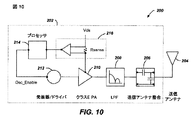
図10は、本発明の例示的な実施形態による送信機の簡略ブロック図である。送信機200は、送信回路202と送信アンテナ204とを含む。一般に、送信回路202は、発振信号を供給することによって送信アンテナ204にRF電力を供給し、その結果、送信アンテナ204の周りに近距離場エネルギーが発生する。例として、送信機200は、13.56MHz ISMバンドにおいて動作することができる。
FIG. 10 is a simplified block diagram of a transmitter according to an exemplary embodiment of the present invention. The
例示的な送信回路202は、送信回路202のインピーダンス(たとえば、50オーム)を送信アンテナ204に整合させるための固定のインピーダンス整合回路206と、受信機108(図1)に結合されたデバイスの自己ジャミングを防ぐレベルまで高調波放出を低減するように構成された低域フィルタ(LPF)208とを含む。他の実施形態は、限定はしないが、他の周波数をパスしながら特定の周波数を減衰させるノッチフィルタを含む様々なフィルタトポロジを含むことができ、また、アンテナへの出力電力または電力増幅器によるDC電流ドローなど、測定可能な送信メトリクスに基づいて変化できる適応型インピーダンス整合を含むことができる。送信回路202は、発振器212によって判断されたRF信号を駆動するように構成された電力増幅器210をさらに含む。送信回路は、ディスクリートデバイスまたは回路からなるか、あるいは代わりに、一体型アセンブリからなることができる。送信アンテナ204からの例示的なRF電力出力は2.5ワットのオーダーである。
The
送信回路202は、特定の受信機に対する送信位相(またはデューティサイクル)中に発振器212を使用可能にし、発振器の周波数を調整し、それらの取り付けられた受信機を通して隣接デバイスと対話するための通信プロトコルを実装するために出力電力レベルを調整するためのプロセッサ214をさらに含む。
The transmit
送信回路202は、送信アンテナ204によって発生された近距離場の近傍におけるアクティブ受信機の存在または不在を検出するための負荷感知回路216をさらに含むことができる。例として、負荷感知回路216は、送信アンテナ204によって発生された近距離場の近傍におけるアクティブ受信機の存在または不在によって影響を及ぼされる、電力増幅器210に流れる電流を監視する。電力増幅器210に対する負荷の変化の検出は、アクティブ受信機と通信するためのエネルギーを送信するために発振器212を使用可能にすべきかどうかを判断する際に使用するために、プロセッサ214によって監視される。
Transmit
送信アンテナ204は、抵抗損を低く保つように選択された厚さ、幅および金属タイプをもつアンテナストリップとして実装できる。従来の実装形態では、送信アンテナ204は、一般に、テーブル、マット、ランプまたは他のより可搬性が低い構成など、より大きい構造物との関連付けのために構成できる。したがって、送信アンテナ204は、一般に、実際的な寸法にするための「巻き」を必要としない。送信アンテナ204の例示的な実装形態は、「電気的に小形」(すなわち、波長の分数)とし、共振周波数を定義するためにキャパシタを使用することによって、より低い使用可能な周波数で共振するように同調させることができる。送信アンテナ204の直径が、または方形ループの場合は、辺の長さが、受信アンテナに対してより大きい(たとえば、0.50メートル)例示的な適用例では、送信アンテナ204は、妥当なキャパシタンスを得るために必ずしも多数の巻きを必要としない。
The transmit
図11は、本発明の一実施形態による受信機のブロック図である。受信機300は、受信回路302と受信アンテナ304とを含む。受信機300は、さらに、それに受信電力を与えるためにデバイス350に結合する。受信機300は、デバイス350の外部にあるものとして示されているが、デバイス350に一体化できることに留意されたい。一般に、エネルギーは、受信アンテナ304にワイヤレスに伝搬され、次いで、受信回路302を通してデバイス350に結合される。
FIG. 11 is a block diagram of a receiver according to an embodiment of the present invention.
受信アンテナ304は、送信アンテナ204(図10)と同じ周波数、または同じ周波数の近くで共振するように同調させられる。受信アンテナ304は、送信アンテナ204と同様に寸法決定でき、または関連するデバイス350の寸法に基づいて別様にサイズ決定できる。例として、デバイス350は、送信アンテナ204の直径または長さよりも小さい直径寸法または長さ寸法を有するポータブル電子デバイスとすることができる。そのような例では、受信アンテナ304は、同調キャパシタ(図示せず)のキャパシタンス値を低減し、受信アンテナのインピーダンスを増加するために、多巻きアンテナとして実装できる。例として、受信アンテナ304は、アンテナ直径を最大にし、受信アンテナのループ巻き(すなわち、巻線)の数および巻線間キャパシタンスを低減するために、デバイス350の実質的な周囲の周りに配置できる。
Receive
受信回路302は、受信アンテナ304に対するインピーダンス整合を行う。受信回路302は、受信したRFエネルギー源を、デバイス350が使用するための充電電力に変換するための電力変換回路306を含む。電力変換回路306は、RF−DC変換器308を含み、DC−DC変換器310をも含むことができる。RF−DC変換器308は、受信アンテナ304において受信されたRFエネルギー信号を非交流電力に整流し、DC−DC変換器310は、整流されたRFエネルギー信号を、デバイス350に適合するエネルギーポテンシャル(たとえば、電圧)に変換する。部分および完全整流器、調整器、ブリッジ、ダブラー、ならびに線形およびスイッチング変換器を含む、様々なRF−DC変換器が企図される。
The
受信回路302は、受信アンテナ304を電力変換回路306に接続するため、または代替的に電力変換回路306を切断するためのスイッチング回路312をさらに含むことができる。電力変換回路306から受信アンテナ304を切断することは、デバイス350の充電を中断するだけでなく、以下でより十分に説明するように、送信機200(図2)から「見た」「負荷」を変化させる。上記で開示したように、送信機200は、送信機電力増幅器210に供給されたバイアス電流の変動を検出する負荷感知回路216を含む。したがって、送信機200は、受信機が送信機の近距離場に存在するときを判断するための機構を有する。
The receiving
複数の受信機300が送信機の近距離場に存在するとき、他の受信機がより効率的に送信機に結合することができるように、1つまたは複数の受信機の装荷および除荷を時間多重化することが望ましいことがある。受信機はまた、他の近くの受信機への結合を解消するため、または近くの送信機に対する装荷を低減するためにクローキングできる。受信機のこの「除荷」を、本明細書では「クローキング」とも呼ぶ。さらに、受信機300によって制御され、送信機200によって検出される除荷と装荷との間のこのスイッチングは、以下でより十分に説明するように受信機300から送信機200への通信機構を与える。さらに、受信機300から送信機200へのメッセージの送信を可能にするプロトコルをスイッチングに関連付けることができる。例として、スイッチング速度は100μ秒のオーダーとすることができる。
When
受信回路302は、送信機から受信機への情報シグナリングに対応する、受信したエネルギー変動を識別するために使用される、シグナリング検出器およびビーコン回路314をさらに含むことができる。さらに、シグナリングおよびビーコン回路314はまた、低減されたRF信号エネルギー(すなわち、ビーコン信号)の送信を検出し、ワイヤレス充電のための受信回路302を構成するために、低減されたRF信号エネルギーを整流して、受信回路302内の無電力供給回路または電力消耗回路のいずれかをアウェイクさせるための公称電力にするために使用できる。
The receiving
受信回路302は、本明細書で説明するスイッチング回路312の制御を含む、本明細書で説明する受信機300のプロセスを調整するためのプロセッサ316をさらに含む。受信機300のクローキングは、デバイス350に充電電力を供給する外部ワイヤード充電ソース(たとえば、ウォール/USB電力)の検出を含む他のイベントの発生時にも行われることがある。プロセッサ316は、受信機のクローキングを制御することに加えて、ビーコン状態を判断し、送信機から送信されたメッセージを抽出するためにビーコン回路314を監視することもできる。プロセッサ316はまた、パフォーマンスの改善ためにDC−DC変換器310を調整することができる。
The
図12に、送信機と受信機との間のメッセージングを実施するための送信回路の一部分の簡略化された概略図を示す。本発明のいくつかの例示的な実施形態では、送信機と受信機との間で通信のための手段を使用可能にすることができる。図12では、電力増幅器210は、送信アンテナ204を励振して放射界を発生させる。電力増幅器は、送信アンテナ204に対して所望の周波数で発振しているキャリア信号220によって駆動される。電力増幅器210の出力を制御するために送信変調信号224が使用される。
FIG. 12 shows a simplified schematic diagram of a portion of a transmission circuit for performing messaging between a transmitter and a receiver. In some exemplary embodiments of the invention, means for communication between the transmitter and the receiver may be enabled. In FIG. 12, the
送信回路は、電力増幅器210に対してオン/オフキーイングプロセスを使用することによって受信機に信号を送信することができる。言い換えれば、送信変調信号224がアサートされたとき、電力増幅器210は、送信アンテナ204に対してキャリア信号220の周波数を励振する。送信変調信号224がネゲートされたとき、電力増幅器は送信アンテナ204に対して周波数を励振しない。
The transmitter circuit can transmit a signal to the receiver by using an on / off keying process for the
図12の送信回路はまた、電力増幅器210に電力を供給し、受信信号235出力を発生する負荷感知回路216を含む。負荷感知回路216では、信号の電力226と電力増幅器210への電力供給228との間で、抵抗Rsの両端間の電圧降下が生じる。電力増幅器210によって消費される電力の変化は、差動増幅器230によって増幅される電圧降下の変化を引き起こす。送信アンテナが受信機中の受信アンテナ(図12に図示せず)との結合モードにあるとき、電力増幅器210によって引き出される電流の量が変化する。言い換えれば、送信アンテナ210の結合モード共振が存在しない場合、放射界を励振するために必要とされる電力が最初の量である。結合モード共振が存在する場合、電力の大部分が受信アンテナに結合されているので、電力増幅器210によって消費される電力の量は上昇する。したがって、受信信号235は、以下で説明するように、送信アンテナ235に結合された受信アンテナの存在を示すことができ、受信アンテナから送信された信号を検出することもできる。さらに、以下で説明するように、受信機電流ドローの変化は、送信機の電力増幅器電流ドローにおいて観測可能であり、この変化を使用して、受信アンテナからの信号を検出することができる。
The transmission circuit of FIG. 12 also includes a
図13A〜図13Cに、受信機と送信機との間のメッセージングを示すための様々な状態における受信回路の一部分の簡略化された概略図を示す。図13A〜図13Cのすべては、様々なスイッチの状態が異なる、同じ回路要素を示す。受信アンテナ304は、ノード350を駆動する特性インダクタンスL1を含む。ノード350は、スイッチS1Aを通して接地に選択的に結合される。ノード350はまた、スイッチS1Bを通してダイオードD1および整流器318に選択的に結合される。整流器318は、受信デバイス(図示せず)への電力供給、バッテリの充電、またはそれらの組合せのために、受信デバイスにDC電力信号322を供給する。ダイオードD1は、高調波および不要な周波数を除去するためにキャパシタC3および抵抗R1を用いてフィルタ処理される送信信号320に結合される。したがって、D1、C3、およびR1の組合せは、送信信号320に対して、図12の送信機を参照しながら上述した送信変調信号224によって発生された送信変調を模する信号を発生させることができる。
13A-13C show simplified schematic diagrams of portions of a receiver circuit in various states to illustrate messaging between a receiver and a transmitter. FIGS. 13A-13C all show the same circuit elements with different switch states. Receiving
本発明の例示的な実施形態は、受信デバイスの電流ドローの変調と、逆方向リンクシグナリングを達成するための受信アンテナのインピーダンスの変調とを含む。図13Aおよび図12を参照すると、受信デバイスの電力ドローが変化すると、負荷感知回路216は、送信アンテナの得られた電力変化を検出し、これらの変化から受信信号235を発生させることができる。
Exemplary embodiments of the present invention include modulation of the current draw of the receiving device and modulation of the impedance of the receiving antenna to achieve reverse link signaling. Referring to FIGS. 13A and 12, when the power draw of the receiving device changes, the
図13A〜図13Cの実施形態では、スイッチS1AおよびS2Aの状態を修正することによって、送信機を通る電流ドローを変化させることができる。図13Aでは、スイッチS1AおよびスイッチS2Aは、どちらも開いており、「DC開状態」を生成し、送信アンテナ204からの負荷を本質的に除去する。これにより、送信機が受ける電流が低減される。
In the embodiment of FIGS. 13A-13C, the current draw through the transmitter can be varied by modifying the state of switches S1A and S2A. In FIG. 13A, switch S1A and switch S2A are both open, creating a “DC open state” and essentially removing the load from transmit
図13Bでは、スイッチS1Aは閉じており、スイッチS2Aは開いており、受信アンテナ304の「DCショート状態」を生成する。したがって、図13Bの状態を使用して、送信機が受ける電流を増加させることができる。
In FIG. 13B, switch S1A is closed and switch S2A is open, generating a “DC short state” for receive
図13Cでは、スイッチS1Aは開いており、スイッチS2Aは閉じており、DCout信号322によって電力を供給することができ、送信信号320を検出することができる通常受信モード(本明細書では「DC動作状態」とも呼ぶ)を生成する。図13Cに示す状態では、受信機は、通常の量の電力を受信し、したがってDC開状態またはDCショート状態よりも多いまたは少ない送信アンテナからの電力を消費する。
In FIG. 13C, switch S1A is open, switch S2A is closed, can be powered by
DC動作状態(図13C)とDCショート状態(図13B)との間のスイッチングによって逆方向リンクシグナリングが達成できる。逆方向リンクシグナリングは、DC動作状態(図13C)とDC開状態(図13A)との間のスイッチングによっても達成できる。 Reverse link signaling can be achieved by switching between the DC operating state (FIG. 13C) and the DC short state (FIG. 13B). Reverse link signaling can also be achieved by switching between a DC operating state (FIG. 13C) and a DC open state (FIG. 13A).
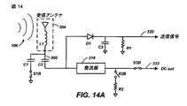
図14A〜図14Cに、受信機と送信機との間のメッセージングを示すための様々な状態における代替受信回路の一部分の簡略化された概略図を示す。 14A-14C show a simplified schematic diagram of a portion of an alternative receiver circuit in various states to illustrate messaging between a receiver and a transmitter.
図14A〜図14Cのすべては、様々なスイッチの状態が異なる、同じ回路要素を示す。受信アンテナ304は、ノード350を駆動する特性インダクタンスL1を含む。ノード350は、キャパシタC1およびスイッチS1Bを通して接地に選択的に結合される。ノード350はまた、キャパシタC2を通してダイオードD1および整流器318にAC結合される。ダイオードD1は、高調波および不要な周波数を除去するためにキャパシタC3および抵抗R1を用いてフィルタ処理される送信信号320に結合される。したがって、D1、C3、およびR1の組合せは、送信信号320に対して、図12の送信機を参照しながら上述した送信変調信号224によって発生された送信変調を模する信号を発生させることができる。
14A-14C all show the same circuit elements with different switch states. Receiving
整流器318は、抵抗R2および接地と直列に接続されたスイッチS2Bに接続される。整流器318はスイッチS3Bにも接続される。スイッチS3Bの反対側は、受信デバイス(図示せず)への電力供給、バッテリの充電、またはそれらの組合せのために、受信デバイスにDC電力信号322を供給する。
図13A〜図13Cでは、受信アンテナ304のDCインピーダンスは、スイッチS1Bを通して受信アンテナを接地に選択的に結合することによって変化させられる。対照的に、図14A〜図14Cの実施形態では、受信アンテナ304のACインピーダンスが変化するようにスイッチS1B、S2B、およびS3Bの状態を修正することによって、アンテナのインピーダンスを修正して逆方向リンクシグナリングを発生させることができる。図14A〜図14Cでは、受信アンテナ304の共振周波数は、キャパシタC2を用いて同調させることができる。したがって、スイッチS1Bを使用してキャパシタC1を通して受信アンテナ304を選択的に結合することによって受信アンテナ304のACインピーダンスを変更し、共振回路を、送信アンテナと最適に結合する範囲の外側にある異なる周波数に本質的に変更することができる。受信アンテナ304の共振周波数がほぼ送信アンテナの共振周波数であり、受信アンテナ304が送信アンテナの近距離場にある場合、受信機が放射界106からかなりの電力を引き出すことができる結合モードが生じる。
In FIGS. 13A-13C, the DC impedance of receive
図14Aでは、スイッチS1Bは閉じており、受信アンテナが送信アンテナの周波数で共振しないので、アンテナを離調し、送信アンテナ204による検出から受信アンテナ304を本質的に「クローキングする」「ACクローキング状態」を生成する。受信アンテナが結合モードにないので、スイッチS2BおよびS3Bの状態は、本議論には特に重要ではない。
In FIG. 14A, switch S1B is closed and the receiving antenna does not resonate at the frequency of the transmitting antenna, thus detuning the antenna and essentially “cloaking” the receiving
図14Bでは、スイッチS1Bは開いており、スイッチS2Bは閉じており、スイッチS3Bは開いており、受信アンテナ304の「同調ダミー負荷状態」を生成する。スイッチS1Bが開いているので、キャパシタC1は共振回路に寄与せず、キャパシタC2と組み合わせた受信アンテナ304は、送信アンテナの共振周波数と整合することができる共振周波数にある。開いたスイッチS3Bと閉じたスイッチS2Bとの組合せは、整流器に対する比較的高い電流ダミー負荷を生成し、受信アンテナ304を通して、送信アンテナによって感知できるより多くの電力を引き出す。さらに、受信アンテナが送信アンテナから電力を受信する状態にあるので、送信信号320を検出することができる。
In FIG. 14B, switch S1B is open, switch S2B is closed, and switch S3B is open, generating a “tuned dummy load state” for receive
図14Cでは、スイッチS1Bは開いており、スイッチS2Bは開いており、スイッチS3Bは閉じており、受信アンテナ304の「同調動作状態」を生成する。スイッチS1Bが開いているので、キャパシタC1は共振回路に寄与せず、キャパシタC2と組み合わせた受信アンテナ304は、送信アンテナの共振周波数と整合することができる共振周波数にある。開いたスイッチS2Bと閉じたスイッチS3Bとの組合せは、DCout322によって電力を供給することができ、送信信号320を検出することができる通常動作状態を生成する。
In FIG. 14C, switch S1B is open, switch S2B is open, and switch S3B is closed, generating a “tuned operating state” of receive
同調動作状態(図14C)とACクローキング状態(図14A)との間のスイッチングによって逆方向リンクシグナリングが達成できる。逆方向リンクシグナリングは、同調ダミー負荷状態(図14B)とACクローキング状態(図14A)との間のスイッチングによっても達成できる。受信機によって消費される電力の量に、送信機中の負荷感知回路によって検出できる差があるので、逆方向リンクシグナリングは、同調動作状態(図14C)と同調ダミー負荷状態(図14B)との間のスイッチングによっても達成できる。 Reverse link signaling can be achieved by switching between the tuned operating state (FIG. 14C) and the AC cloaking state (FIG. 14A). Reverse link signaling can also be achieved by switching between a tuned dummy load state (FIG. 14B) and an AC cloaking state (FIG. 14A). Since there is a difference in the amount of power consumed by the receiver that can be detected by a load sensing circuit in the transmitter, the reverse link signaling is between the tuned operating state (FIG. 14C) and the tuned dummy load state (FIG. 14B). It can also be achieved by switching between them.
もちろん、当業者なら、スイッチS1B、S2B、およびS3Bの他の組合せを使用して、クローキングを生成し、逆方向リンクシグナリングを発生させ、受信デバイスに電力を供給することができることを認識されよう。さらに、クローキング、逆方向リンクシグナリング、および受信デバイスへの電力供給のための他の可能な組合せを生成するために、スイッチS1AおよびS1Bを図14A〜図14Cの回路に追加することができる。 Of course, those skilled in the art will recognize that other combinations of switches S1B, S2B, and S3B can be used to generate cloaking, generate reverse link signaling, and provide power to the receiving device. In addition, switches S1A and S1B can be added to the circuits of FIGS. 14A-14C to generate other possible combinations for cloaking, reverse link signaling, and powering the receiving device.
したがって、図12を参照しながら上述したように、結合モードにあるとき、送信機から受信機に信号を送信することができる。さらに、図13A〜図13Cおよび図14A〜図14Cを参照しながら上述したように、結合モードにあるとき、受信機から送信機に信号を送信することができる。 Thus, as described above with reference to FIG. 12, when in the combined mode, a signal can be transmitted from the transmitter to the receiver. Further, as described above with reference to FIGS. 13A-13C and 14A-14C, a signal can be transmitted from the receiver to the transmitter when in the combined mode.
図15A〜図15Cは、上述のシグナリング技法を使用する、送信機と受信機との間の通信のためのメッセージングプロトコルを示すタイミング図である。1つの例示的な手法では、送信機から受信機への信号を本明細書では「順方向リンク」と呼び、通常発振と発振なしとの間の単純なAM変調を使用する。他の変調技法も企図される。非限定的な例として、信号存在を1と解釈し、信号不在を0と解釈することができる。 15A-15C are timing diagrams illustrating a messaging protocol for communication between a transmitter and a receiver using the signaling techniques described above. In one exemplary approach, the signal from the transmitter to the receiver is referred to herein as the “forward link” and uses simple AM modulation between normal oscillation and no oscillation. Other modulation techniques are also contemplated. As a non-limiting example, signal presence can be interpreted as 1 and signal absence can be interpreted as 0.
逆方向リンクシグナリングは、送信機中の負荷感知回路によって検出できる、受信デバイスによって引き出された電力の変調によって行われる。非限定的な例として、高電力状態を1と解釈し、低電力状態を0と解釈することができる。受信機が逆方向リンクシグナリングを実行することができるように、送信機がオンでなければならないことに留意されたい。さらに、受信機は、順方向リンクシグナリング中に逆方向リンクシグナリングを実行してはならない。さらに、2つの受信デバイスが同時に逆方向リンクシグナリングを実行しようと試みた場合、衝突が起こることがあり、それにより送信機が適切な逆方向リンク信号を復号することが、不可能でないとしても困難になる。 Reverse link signaling is performed by modulation of the power drawn by the receiving device, which can be detected by a load sensing circuit in the transmitter. As a non-limiting example, a high power state can be interpreted as 1 and a low power state can be interpreted as 0. Note that the transmitter must be on so that the receiver can perform reverse link signaling. In addition, the receiver must not perform reverse link signaling during forward link signaling. In addition, if two receiving devices attempt to perform reverse link signaling at the same time, a collision may occur, which makes it difficult, if not impossible, for the transmitter to decode the proper reverse link signal. become.
本明細書で説明する例示的な実施形態では、シグナリングは、スタートビットと、データバイトと、パリティービットと、ストップビットとをもつUniversal Asynchronous Receive Transmit(UART)シリアル通信プロトコルと同様である。もちろん、どんなシリアル通信プロトコルも、本明細書で説明する本発明の例示的な実施形態を実施するのに好適である。限定としてではなく、説明を簡単にするために、各バイト送信を通信するための期間が約10mSであるものとして、メッセージングプロトコルについて説明する。 In the exemplary embodiment described herein, the signaling is similar to the Universal Asynchronous Receive Transmit (UART) serial communication protocol having a start bit, a data byte, a parity bit, and a stop bit. Of course, any serial communication protocol is suitable for implementing the exemplary embodiments of the invention described herein. For ease of explanation, but not as a limitation, the messaging protocol will be described assuming that the duration for communicating each byte transmission is about 10 ms.
図15Aは、メッセージングプロトコルの最も単純で、最も低電力の形態を示す。同期パルス420は循環期間410(例示的な実施形態では約1秒)ごとに反復される。非限定的な例として、同期パルスオン時間は約40mSとすることができる。少なくとも同期パルス420をもつ循環期間410は、送信機がオンの間、無期限に反復できる。同期パルス350は、「白」パルス420’によって示されるパルス周期の間、一定の周波数とすることができるので、「同期パルス」はいくぶん誤称であることに留意されたい。同期パルス420はまた、「ハッチ」パルス420によって示される、上述したオン/オフキーイングを用いた共振周波数におけるシグナリングを含むことができる。図15Aは、同期パルス420中に共振周波数における電力が供給され、電力期間450中に送信アンテナがオフである、最小電力状態を示す。すべての受信デバイスは、同期パルス420中に電力を受信することが可能である。
FIG. 15A shows the simplest and lowest power form of the messaging protocol. The
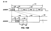
図15Bは、同期パルス420と、逆方向リンク期間430と、電力期間450’とをもつ循環期間410を示し、送信アンテナはオンであり、共振周波数において発振することによって全電力を供給しており、シグナリングは実行していない。上側のタイミング図は循環期間410全体を示し、下側のタイミング図は同期パルス420および逆方向リンク期間430の分解図を示す。電力期間450’は、以下で説明するように、複数の受信デバイスのための異なる期間にセグメント化できる。図15Bは、3つの異なる受信デバイスのための3つの電力セグメントPd1、Pd2、およびPdnを示す。
FIG. 15B shows a
順方向リンクシグナリングが行われるとき、同期パルス420は、ウォームアップ期間422と、順方向リンク期間424と、リスニング期間426とを含むことができる。リスニング期間426は、ハンドオーバ期間427と逆方向リンク開始期間428とを含むことができる。同期パルス420の間、送信機は、(「ハッチ」セクションによって示される)順方向リンク期間400中に順方向リンクメッセージを送出し、リスニング期間426中に受信機からの応答を待つ。図15Bでは、受信機は応答せず、これはリスニング期間426中の「白」セクションによって示されている。
When forward link signaling occurs, the
図15Cは、受信機が、「クロスハッチ」セクションによって示される逆方向リンク開始期間428および逆方向リンク期間430中に応答することを除いて図15Bと同様である。図15では、同期パルス420の間、送信機は、順方向リンク期間400中に順方向リンクメッセージを送出し、リスニング期間426中に受信機からの応答を待つ。応答しようとしている受信機は、ハンドオーバ期間427の終了の前、逆方向リンク開始期間428中、場合によっては逆方向リンク期間430中にそれらの応答を開始する。
FIG. 15C is similar to FIG. 15B except that the receiver responds during the reverse
非限定的な例として、表2に、送信機および受信機によって送信されるいくつかの可能なメッセージを示す。
ただし、
ヌル=送信コマンドなし
DD=デバイス番号
TT=デバイスタイプ
PP=要求される電力
rr=乱数
cc=チェックサム
NN=タイムスロットの開始、および
MM=タイムスロットの終了
表2の説明において、ヌルコマンドは、送信機が順方向リンク期間424中にメッセージングを送信しないことを意味する。行2において、送信機は新デバイス照会(NDQ)を送信する。受信デバイスが応答する場合、受信デバイスは、デバイス番号(デバイス番号が送信機によって割り当てられるまで、新しいデバイスでは0であるはずである)、電力要求、乱数、および受信応答中のすべてのデータビットのチェックサムとともに新デバイス応答(NDR)で応答する。
However,
Null = no send command DD = device number TT = device type PP = required power rr = random number cc = checksum NN = start of time slot and MM = end of time slot In the description of Table 2, the null command is This means that the transmitter does not send messaging during the
行3において、送信機は、デバイス照会(DQ)をデバイス番号とともに送信する。DQ応答によって指定された受信デバイスは、デバイス番号、デバイスタイプ、要求される電力の量、受信応答中のすべてのデータビットのチェックサムとともに、デバイスステータス(DS)で応答する。
In
行4において、送信機は、確認応答(ACK)を、前のDQに応答した受信機に送出する。受信機はACKには応答しない。 In line 4, the transmitter sends an acknowledgment (ACK) to the receiver that responded to the previous DQ. The receiver does not respond to ACK.
行5において、送信機は、デバイス番号、電力期間450’内の開始時間、電力期間450’内の終了時間、および受信応答中のすべてのデータビットのチェックサムとともにスロット割当て(SA)を送出する。受信機はSAには応答しない。
In
行6において、送信機は、すべての受信機が、それらの割り当てられたタイムスロットの使用を停止しなければならないことを示すリセット(RES)を送出する。受信機はRESには応答しない。
In
もちろん、当業者なら、コマンドおよび応答は例示的なものであり、本発明の範囲内で企図される様々な実施形態では、これらのコマンドおよび応答の変形体を使用することができ、本発明の範囲内で追加のコマンドおよび応答が考案できることを認識されよう。 Of course, those skilled in the art will appreciate that the commands and responses are exemplary, and that various variations of these commands and responses can be used in various embodiments contemplated within the scope of the present invention. It will be appreciated that additional commands and responses can be devised within the scope.
通信がどのように行われるかをさらに示すために、5つの異なるシナリオについて論じる。第1のシナリオでは、最初に送信機の結合モード領域内に受信デバイスはなく、1つの受信デバイスが結合モード領域に入る。結合モード領域中にデバイスが存在しないとき、送信機は、図15Aに示すように低電力状態のままであり、循環期間410ごとに同期パルス420を反復する。同期パルス420は順方向リンク期間424中にNDQを含み、送信機はリスニング期間426中に応答をリッスンする。応答が受信されない場合、送信機は、次の循環期間410の同期パルス420のための時間まで停止する。
To further illustrate how communication takes place, five different scenarios are discussed. In the first scenario, there is initially no receiving device in the combined mode area of the transmitter and one receiving device enters the combined mode area. When there are no devices in the combined mode region, the transmitter remains in a low power state as shown in FIG. 15A and repeats the
新しい受信デバイスが結合モード領域に導入されたとき、受信デバイスは、最初にオンになり、同期パルス420をリッスンする。新しい受信デバイスは、電力のために同期パルス420を使用することができるが、電力期間450’中にクローキングまたは非電力受信モードに進まなければならない(本明細書では「バスから降りる」と呼ぶ)。さらに、新しい受信デバイスは、送信コマンドをリッスンし、NDQを除いてすべての送信コマンドを無視する。新しい受信デバイスは、NDQを受信すると、ハンドオーバ期間427、逆方向リンク開始期間428、場合によっては逆方向リンク期間430の間、オンのままになる。順方向リンク期間424後、ハンドオーバ期間427の終了の前に、受信デバイスは、デバイスID0(新しいデバイスIDは送信機によって割り当てられる)、電力量要求、乱数およびチェックサムとともにNDRで応答する。新しい受信デバイスは、次いで、電力期間450’中にバスから降りる。
When a new receiving device is introduced into the combined mode region, the receiving device is first turned on and listens for a
送信機がNDRを正しく受信した場合、送信機は、次の同期パルス420上で新しい受信デバイスのためのスロット割当て(SA)で応答する。SAは、新しい受信デバイスのデバイスIDと、開始時間と、終了時間と、チェックサムとを含む。このSAの開始時間および終了時間は0であり、新しい受信デバイスが電力期間450’中のどの時間期間にもバスに乗ってはならないことを示す。新しい受信デバイスは、それがバスに乗ることができるとき、特定の電力セグメントPdnを割り当てる実際の開始時間および終了時間とともに後続のSAを受信する。新しい受信デバイスが適切なチェックサムを受信しない場合、新しい受信デバイスは新デバイスモードのままになり、再びNDQに応答する。
If the transmitter receives the NDR correctly, the transmitter responds with a slot assignment (SA) for the new receiving device on the
第2のシナリオでは、送信機の結合モード領域内に受信デバイスはなく、2つ以上の受信デバイスが結合モード領域に入る。このモードでは、2つの新しい受信デバイスが結合モード領域に導入されたとき、それらは最初にずっとバスに乗っている。新しい受信デバイスは、同期パルス420を受信すると、電力のために同期パルス420を使用することができるが、電力期間450’中にバスから降りなければならない。さらに、新しい受信デバイスは、送信コマンドをリッスンし、NDQを除いてすべての送信コマンドを無視する。新しい受信デバイスは、NDQを受信すると、ハンドオーバ期間427、逆方向リンク開始期間428、場合によっては逆方向リンク期間430の間、オンのままになる。順方向リンク期間424後、ハンドオーバ期間427の終了の前に、受信デバイスは、デバイスID0(新しいデバイスIDは送信機によって割り当てられる)、電力量要求、乱数およびチェックサムとともにNDRで応答する。
In the second scenario, there are no receiving devices in the combined mode region of the transmitter, and two or more receiving devices enter the combined mode region. In this mode, when two new receiving devices are introduced into the combined mode area, they are initially on the bus all the time. When a new receiving device receives the
しかしながら、2つ以上の受信デバイスが同時に応答しており、異なる乱数およびチェックサムを有する可能性があるので、送信機によって受信されたメッセージは歪曲され、送信機におけるチェックサムは不正確になる。したがって、送信機は、後続の同期パルス420上でSAを送出しない。
However, since two or more receiving devices are responding simultaneously and may have different random numbers and checksums, messages received by the transmitter are distorted and the checksum at the transmitter is inaccurate. Thus, the transmitter does not send SA on
NDR後に即時のSAが利用できない場合、受信デバイスの各々は、NDRで応答する前にランダムな数の後続のNDQを待つ。たとえば、2つのデバイスが両方とも第1のNDQに応答すると、後続のSAは生じない。デバイス1は、別のNDQに応答する前に4つのNDQを待つことを決定する。デバイス2は、別のNDQに応答する前に2つのNDQを待つことを決定する。したがって、送信機によって送出される次のNDQに対して、どちらのデバイスもNDRで応答しない。送信機によって送出される次のNDQに対して、デバイス2のみがNDRで応答し、送信機は、NDRをうまく受信し、デバイス2のためのSAを送出する。次のNDQに対して、デバイス2は、それがもはや新しいデバイスではないので応答せず、デバイス1は、そのランダムな待機期間が経過していないので応答しない。送信機によって送出される次のNDQに対して、デバイス1のみがNDRで応答し、送信機は、NDRをうまく受信し、デバイス1のためのSAを送出する。
If no immediate SA is available after NDR, each of the receiving devices waits for a random number of subsequent NDQs before responding with NDR. For example, if both devices respond to the first NDQ, no subsequent SA occurs.
第3のシナリオでは、少なくとも1つの受信デバイスが結合モード領域中にあり、新しい受信デバイスが結合モード領域に入る。このモードでは、新しい受信デバイスが結合モード領域に導入され、最初にずっとバスに乗っている。新しい受信デバイスは、同期パルス420を受信すると、電力のために同期パルス420を使用することができるが、電力期間450’中にバスから降りなければならない。さらに、新しい受信デバイスは、送信コマンドをリッスンし、NDQを除いてすべての送信コマンドを無視する。周期的に、送信機は、新しいデバイスが結合モード領域に入ったかどうかを確かめるためにNDQを発行する。新しいデバイスは、次いでNDRで応答する。後続の同期パルス420上で、送信機は、割り当てられた電力スロットなしの、新しいデバイスのためのSAを発行する。送信機は、次いで、結合モード領域中のすべてのデバイスのための電力割振りを再計算し、重複電力セグメントPdnがないように、各デバイスのための新しいSAを発生する。各デバイスは、その新しいSAを受信した後、その新しいPdn中にのみバスに乗ることを開始する。
In the third scenario, at least one receiving device is in the combined mode region and a new receiving device enters the combined mode region. In this mode, a new receiving device is introduced into the combined mode area and is initially on the bus all the time. When a new receiving device receives the
第4のシナリオでは、受信デバイスが結合モード領域に出入りすることなしに通常の電力供給動作が続く。このシナリオの間、送信機は、各デバイスをデバイス照会(DQ)で周期的にピングする。照会されたデバイスはデバイスステータス(DS)で応答する。DSが異なる電力要求を示した場合、送信機は、結合モード領域中のデバイスの各々に対する電力割振りを再割振りすることができる。送信機はまた、第3のシナリオに関して上記で説明したように、NDQを周期的に発行する。 In the fourth scenario, the normal power supply operation continues without the receiving device entering or exiting the combined mode region. During this scenario, the transmitter periodically pings each device with a device inquiry (DQ). The queried device responds with a device status (DS). If the DS indicates a different power requirement, the transmitter can reallocate the power allocation for each of the devices in the combined mode region. The transmitter also periodically issues NDQ as described above for the third scenario.
第5のシナリオでは、デバイスは結合モード領域から除去される。この「除去された」状態は、デバイスが結合モード領域から物理的に除去されること、デバイスが遮断されること、または、おそらくデバイスがそれ以上の電力を必要としないので、自体をクローキングすることとすることができる。上述のように、送信機は、結合モード領域中のすべてのデバイスに対して周期的にDQを送出する。特定のデバイスへの2つの連続するDQが有効なDSを戻さない場合、送信機は、割り振られたデバイスのそのリストからそのデバイスを除去し、電力期間450’を残りのデバイスに再割振りする。送信機はまた、消失したデバイスがまだ受信しているが送信することができない場合、消失したデバイスに0時間の電力割振りを割り当てる。デバイスが間違って電力割振りから除去された場合、デバイスは、適切なNDRでNDQに応答することによって電力割振りを回復することができる。 In the fifth scenario, the device is removed from the combined mode region. This “removed” state means that the device is physically removed from the coupled mode region, the device is shut down, or perhaps cloaking itself because it does not require any more power. It can be. As described above, the transmitter periodically sends DQs to all devices in the combined mode region. If two consecutive DQs to a particular device do not return a valid DS, the transmitter removes that device from its list of allocated devices and reallocates the power period 450 'to the remaining devices. The transmitter also allocates a zero hour power allocation to the lost device if the lost device is still receiving but unable to transmit. If a device is accidentally removed from the power allocation, the device can recover the power allocation by responding to NDQ with the appropriate NDR.
表3に、通信プロトコルがどのように動作するかを示すために、コマンドおよび応答の非限定的なシーケンスを示す。
新しいデバイスのための最初のスロット割当てはタイムスロットを割り振らないことに留意されたい。各既存デバイスに新しい非重複タイムスロットが割り振られ、次いで、新しいデバイスに、電力を受信するためのタイムスロットが最後に割り振られる。 Note that the initial slot assignment for a new device does not allocate a time slot. Each existing device is assigned a new non-overlapping time slot, and then the new device is finally assigned a time slot for receiving power.
例示的な一実施形態では、ワイヤレス充電デバイスは、たとえば、デバイスがうまく充電領域に入り、自体をローカル送信機に登録したことを示すライトなどの可視信号をユーザに対して表示することができる。これは、デバイスが実際に充電する準備ができているという肯定のフィードバックをユーザに与える。 In one exemplary embodiment, the wireless charging device may display a visible signal to the user, such as a light indicating that the device has successfully entered the charging area and registered itself with the local transmitter, for example. This gives the user positive feedback that the device is actually ready to charge.
本発明の他の例示的な実施形態では、受信機と送信機は、図2に示すように別個の通信チャネル119(たとえば、Bluetooth(登録商標)、ZigBee、セルラーなど)上で通信することができる。別個の通信チャネルの場合、循環期間は通信期間を含む必要がなく、時間全体を電力期間450’に充てることができる。送信機は依然として(別個の通信チャネルを介して通信される)各受信デバイスにタイムスロットを割り振ることができ、各受信デバイスはその割り当てられた電力セグメントPdnの間にバスに乗るだけである。 In other exemplary embodiments of the invention, the receiver and transmitter may communicate on separate communication channels 119 (eg, Bluetooth®, ZigBee, cellular, etc.) as shown in FIG. it can. In the case of a separate communication channel, the circulation period need not include the communication period, and the entire time can be devoted to the power period 450 '. The transmitter can still allocate a time slot to each receiving device (communicated via a separate communication channel), and each receiving device only gets on the bus during its assigned power segment Pdn.
上述の時分割多重化電力割振りは、送信機の結合モード領域内の複数の受信デバイスに電力を供給するための最も効率的な方法であることがある。しかしながら、他の電力割振りシナリオを本発明の他の実施形態とともに採用することができる。 The time division multiplexed power allocation described above may be the most efficient way to supply power to multiple receiving devices in the combined mode region of the transmitter. However, other power allocation scenarios can be employed with other embodiments of the present invention.
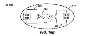
図16A〜図16Dは、送信機と1つまたは複数の受信機との間で電力を送信するためのビーコン電力モードを示す簡略ブロック図である。図16Aは、受信デバイスがビーコン結合モード領域510にないときの低電力「ビーコン」信号525を有する送信機520を示す。ビーコン信号525は、非限定的な例として、約10〜約20mW RFの範囲内などにあるとすることができる。この信号は、充電すべきデバイスが結合モード領域中に配置されたとき、デバイスに初期電力を供給するのに十分である。
16A-16D are simplified block diagrams illustrating beacon power modes for transmitting power between a transmitter and one or more receivers. FIG. 16A shows a
図16Bは、ビーコン信号525を送信している送信機520のビーコン結合モード領域510内に配置された受信デバイス530を示す。受信デバイス530がオンであり、送信機との結合を生じる場合、受信デバイス530は、まさに受信機がビーコン信号525から電力を受容する逆方向リンク結合535を発生する。この追加の電力は、送信機の負荷感知回路216(図12)によって感知できる。したがって、送信機は高電力モードに進むことができる。
FIG. 16B shows a receiving
図16Cは、高電力信号525’を発生し、高電力結合モード領域510’を生じている送信機520を示す。受信デバイス530が電力を受容しており、その結果、逆方向リンク結合535を発生している限り、送信機は高電力状態のままである。ただ1つの受信デバイス530が示されているが、複数の受信デバイス530が結合モード領域510中に存在することができる。複数の受信デバイス530がある場合、それらは、各受信デバイス530がどのくらい良好に結合されるかに基づいて、送信機によって送信される電力の量を共有する。たとえば、結合効率は、図8および図9を参照しながら上記で説明したように、デバイスが結合モード領域510内のどこに配置されるかに応じて、受信デバイス530ごとに異なることがある。
FIG. 16C shows a
図16Dは、受信デバイス530がビーコン結合モード領域510中にあるときでも、ビーコン信号525を発生している送信機520を示す。受信デバイス530が遮断されたとき、またはおそらく受信デバイス530がそれ以上の電力を必要としないので、デバイスが自体をクローキングするとき、この状態が起こることがある。
FIG. 16D shows
時間多重化モードの場合と同様に、受信機と送信機は、別個の通信チャネル(たとえば、Bluetooth、ZigBeeなど)上で通信することができる。別個の通信チャネルの場合、送信機は、結合モード領域510中の受信デバイスの数とそれらのそれぞれの電力要件とに基づいて、ビーコンモードと高電力モードとの間でいつ切り替えるべきかを判断し、または複数の電力レベルを生成することができる。
As in the time multiplexed mode, the receiver and transmitter can communicate on separate communication channels (eg, Bluetooth, ZigBee, etc.). For separate communication channels, the transmitter determines when to switch between beacon mode and high power mode based on the number of receiving devices in combined
情報および信号は様々な異なる技術および技法のいずれかを使用して表すことができることを、当業者は理解されよう。たとえば、上記の説明全体にわたって言及されるデータ、命令、コマンド、情報、信号、ビット、シンボル、およびチップは、電圧、電流、電磁波、磁界または磁性粒子、光場または光学粒子、あるいはそれらの任意の組合せによって表すことができる。 Those of skill in the art will understand that information and signals may be represented using any of a variety of different technologies and techniques. For example, data, instructions, commands, information, signals, bits, symbols, and chips referred to throughout the above description may be voltages, currents, electromagnetic waves, magnetic fields or magnetic particles, light fields or optical particles, or any of them Can be represented by a combination.
さらに、本明細書で開示した実施形態に関して説明した様々な例示的な論理ブロック、モジュール、回路、およびアルゴリズムステップは、電子ハードウェア、コンピュータソフトウェア、または両方の組合せとして実装できることを当業者なら諒解されよう。ハードウェアとソフトウェアのこの互換性を明確に示すために、様々な例示的な構成要素、ブロック、モジュール、回路、およびステップを、上記では概してそれらの機能に関して説明した。そのような機能をハードウェアとして実装するか、ソフトウェアとして実装するかは、特定の適用例および全体的なシステムに課される設計制約に依存する。当業者は、説明した機能を特定の適用例ごとに様々な方法で実装することができるが、そのような実装の決定は、本発明の範囲からの逸脱を生じるものと解釈すべきではない。 Further, those skilled in the art will appreciate that the various exemplary logic blocks, modules, circuits, and algorithm steps described with respect to the embodiments disclosed herein can be implemented as electronic hardware, computer software, or a combination of both. Like. To clearly illustrate this interchangeability of hardware and software, various illustrative components, blocks, modules, circuits, and steps have been described above generally in terms of their functionality. Whether such functionality is implemented as hardware or software depends upon the particular application and design constraints imposed on the overall system. Those skilled in the art can implement the described functionality in a variety of ways for each particular application, but such implementation decisions should not be construed as departing from the scope of the invention.
本明細書で開示した実施形態に関連して説明した様々な例示的な論理ブロック、モジュール、および回路は、汎用プロセッサ、デジタル信号プロセッサ(DSP)、特定用途向け集積回路(ASIC)、フィールドプログラマブルゲートアレイ(FPGA)または他のプログラマブル論理デバイス、個別ゲートまたはトランジスタロジック、個別ハードウェア構成要素、あるいは本明細書に記載の機能を実行するように設計されたそれらの任意の組合せを用いて実装または実行できる。汎用プロセッサはマイクロプロセッサとすることができるが、代替として、プロセッサは、任意の従来のプロセッサ、コントローラ、マイクロコントローラ、または状態機械とすることができる。プロセッサは、コンピューティングデバイスの組合せ、たとえば、DSPとマイクロプロセッサとの組合せ、複数のマイクロプロセッサ、DSPコアと連携する1つまたは複数のマイクロプロセッサ、あるいは任意の他のそのような構成として実装することもできる。 Various exemplary logic blocks, modules, and circuits described in connection with the embodiments disclosed herein include general purpose processors, digital signal processors (DSPs), application specific integrated circuits (ASICs), field programmable gates. Implemented or implemented using an array (FPGA) or other programmable logic device, individual gate or transistor logic, individual hardware components, or any combination thereof designed to perform the functions described herein it can. A general purpose processor may be a microprocessor, but in the alternative, the processor may be any conventional processor, controller, microcontroller, or state machine. A processor may be implemented as a combination of computing devices, eg, a combination of a DSP and a microprocessor, a plurality of microprocessors, one or more microprocessors associated with a DSP core, or any other such configuration. You can also.
本明細書で開示する実施形態に関して説明する方法またはアルゴリズムのステップは、直接ハードウェアで実施するか、プロセッサによって実行されるソフトウェアモジュールで実施するか、またはその2つの組合せで実施することができる。ソフトウェアモジュールは、ランダムアクセスメモリ(RAM)、フラッシュメモリ、読取り専用メモリ(ROM)、電気的プログラマブルROM(EPROM)、電気的消去可能プログラマブルROM(EEPROM)、レジスタ、ハードディスク、リムーバブルディスク、CD−ROM、または当技術分野で知られている任意の他の形態の記憶媒体中に常駐することができる。例示的な記憶媒体は、プロセッサが記憶媒体から情報を読み取り、記憶媒体に情報を書き込むことができるように、プロセッサに結合される。代替として、記憶媒体はプロセッサに一体化することができる。プロセッサおよび記憶媒体はASIC中に常駐することができる。ASICはユーザ端末中に常駐することができる。代替として、プロセッサおよび記憶媒体は、ユーザ端末中に個別構成要素として常駐することができる。 The method or algorithm steps described in connection with the embodiments disclosed herein may be implemented directly in hardware, implemented in software modules executed by a processor, or a combination of the two. Software modules include random access memory (RAM), flash memory, read only memory (ROM), electrically programmable ROM (EPROM), electrically erasable programmable ROM (EEPROM), registers, hard disk, removable disk, CD-ROM, Or it can reside in any other form of storage medium known in the art. An exemplary storage medium is coupled to the processor such that the processor can read information from, and write information to, the storage medium. In the alternative, the storage medium may be integral to the processor. The processor and the storage medium can reside in the ASIC. The ASIC can reside in the user terminal. In the alternative, the processor and the storage medium may reside as discrete components in a user terminal.
1つまたは複数の例示的な実施形態では、説明した機能はハードウェア、ソフトウェア、ファームウェア、またはその任意の組合せで実装できる。ソフトウェアで実装する場合、機能は、1つまたは複数の命令またはコードとしてコンピュータ可読媒体上に記憶するか、あるいはコンピュータ可読媒体を介して送信することができる。コンピュータ可読媒体は、ある場所から別の場所へのコンピュータプログラムの転送を可能にする任意の媒体を含む、コンピュータ記憶媒体と通信媒体の両方を含む。記憶媒体は、コンピュータによってアクセスできる任意の利用可能な媒体でよい。限定ではなく例として、そのようなコンピュータ可読媒体は、RAM、ROM、EEPROM、CD−ROMもしくは他の光ディスク記憶装置、磁気ディスク記憶装置もしくは他の磁気記憶デバイス、または命令もしくはデータ構造の形態の所望のプログラムコードを担持または記憶するために使用でき、コンピュータによってアクセスできる任意の他の媒体を備えることができる。また、いかなる接続もコンピュータ可読媒体と適切に呼ばれる。たとえば、ソフトウェアが、同軸ケーブル、光ファイバケーブル、ツイストペア、デジタル加入者回線(DSL)、または赤外線、無線、およびマイクロ波などのワイヤレス技術を使用して、ウェブサイト、サーバ、または他のリモートソースから送信される場合、同軸ケーブル、光ファイバケーブル、ツイストペア、DSL、または赤外線、無線、およびマイクロ波などのワイヤレス技術は、媒体の定義に含まれる。本明細書で使用するディスク(disk)およびディスク(disc)は、コンパクトディスク(disc)(CD)、レーザディスク(disc)、光ディスク(disc)、デジタル多用途ディスク(disc)(DVD)、フロッピー(登録商標)ディスク(disk)およびブルーレイディスク(disc)を含み、ディスク(disk)は、通常、データを磁気的に再生し、ディスク(disc)は、データをレーザで光学的に再生する。上記の組合せもコンピュータ可読媒体の範囲内に含めるべきである。 In one or more exemplary embodiments, the functions described can be implemented in hardware, software, firmware, or any combination thereof. If implemented in software, the functions may be stored on or transmitted over as one or more instructions or code on a computer-readable medium. Computer-readable media includes both computer storage media and communication media including any medium that enables transfer of a computer program from one place to another. A storage media may be any available media that can be accessed by a computer. By way of example, and not limitation, such computer-readable media may be RAM, ROM, EEPROM, CD-ROM or other optical disk storage device, magnetic disk storage device or other magnetic storage device, or desired in the form of instructions or data structures. Any other medium that can be used to carry or store the program code and that can be accessed by a computer can be provided. Any connection is also properly termed a computer-readable medium. For example, the software can use a coaxial cable, fiber optic cable, twisted pair, digital subscriber line (DSL), or wireless technology such as infrared, wireless, and microwave, from a website, server, or other remote source When transmitted, coaxial technologies, fiber optic cables, twisted pair, DSL, or wireless technologies such as infrared, radio, and microwave are included in the media definition. Discs and discs used in this specification are compact discs (CD), laser discs, optical discs, digital versatile discs (DVDs), floppy discs (discs). Including a registered trademark disk and a Blu-ray disc, the disk normally reproducing data magnetically, and the disk optically reproducing data with a laser. Combinations of the above should also be included within the scope of computer-readable media.
開示した例示的な実施形態の前述の説明は、当業者が本発明を実施または使用できるようにするために提供されるものである。これらの例示的な実施形態への様々な修正は当業者には容易に明らかであり、本明細書で定義した一般原理は、本発明の趣旨または範囲から逸脱することなく他の実施形態に適用できる。したがって、本発明は、本明細書で示した実施形態に限定されるものではなく、本明細書で開示した原理および新規の特徴に合致する最も広い範囲を与えられるべきである。
以下に、本願出願の当初の特許請求の範囲に記載された発明を付記する。
[C1] 送信アンテナの近距離場内で低電力ビーコンモードにおいて結合モード領域を生成するために前記送信アンテナの共振周波数において電磁界を発生させることと、前記結合モード領域中で実質的に前記共振周波数の近くで動作する受信アンテナを用いて前記電磁界からの電力を消費することを備える、受信機応答で前記低電力ビーコンモードに応答することと、前記受信機応答の前に対する、受信機応答中に前記電磁界に供給される電力の差を検出することによって、前記低電力ビーコンモードへの前記受信機応答を検出することと、前記受信機応答に応答して高電力充電モードにおいて前記電磁界を発生させることとを備えるワイヤレス電力伝達の方法。
[C2] 前記結合モード領域中で実質的に前記共振周波数の近くで動作する少なくとも1つの追加の受信アンテナを用いて前記電磁界からの電力を消費することをさらに備え、前記電磁界中の前記電力の少なくとも一部が前記受信アンテナによって消費され、前記電磁界中の前記電力の少なくとも一部が前記少なくとも1つの追加の受信アンテナによって消費される、[C1]に記載の方法。
[C3] 前記受信アンテナによって消費される前記電磁界からの電力の量を実質的に減少させることによって前記受信機応答を修正することと、前記受信機応答に対する、前記修正された受信機応答中に前記電磁界に供給される電力の差を検出することによって、前記修正された受信機応答を検出することと、前記修正された受信機応答に応答して前記電磁界を前記低電力ビーコンモードに戻すこととをさらに備える、[C1]に記載の方法。
[C4] 前記受信機応答を修正することが、前記受信アンテナから電力を除去することと、前記結合モード領域から前記受信アンテナを除去することと、前記受信アンテナの前記共振周波数を修正することによって前記受信アンテナをクローキングすることとからなる群から選択される動作を備える、[C3]に記載の方法。
[C5] 前記結合モード領域中で実質的に前記共振周波数の近くで動作する前記受信アンテナの存在を通信することをさらに備え、前記通信することが、前記受信アンテナに動作可能に結合された受信機と、前記送信アンテナのワイヤレスチャネルとは異なるワイヤレスチャネルによって前記送信アンテナに動作可能に結合された送信機との間で行われる、[C1]に記載の方法。
[C6] 送信アンテナの近距離場内で低電力ビーコンモードにおいて結合モード領域を生成するために前記送信アンテナの共振周波数において電磁界を発生させるための手段と、前記結合モード領域中で実質的に前記共振周波数の近くで動作する受信アンテナを用いて前記電磁界からの電力を消費することを備える、受信機応答で前記低電力ビーコンモードに応答するための手段と、前記受信機応答の前に対する、受信機応答中に前記電磁界に供給される電力の差を検出することによって、前記低電力ビーコンモードへの前記受信機応答を検出するための手段と、前記受信機応答に応答して高電力充電モードにおいて前記電磁界を発生させるための手段とを備えるワイヤレス電力伝達のためのシステム。
[C7] 前記結合モード領域中で実質的に前記共振周波数の近くで動作する少なくとも1つの追加の受信アンテナを用いて、前記電磁界からの電力を消費するための手段をさらに備え、前記電磁界中の前記電力の少なくとも一部が前記受信アンテナによって消費され、前記電磁界中の前記電力の少なくとも一部が前記少なくとも1つの追加の受信アンテナによって消費される、[C6]に記載のシステム。
[C8] 前記受信アンテナによって消費される前記電磁界からの電力の量を実質的に減少させることによって前記受信機応答を修正するための手段と、前記受信機応答に対する、前記修正された受信機応答中に前記電磁界に供給される電力の差を検出することによって、前記修正された受信機応答を検出するための手段と、前記修正された受信機応答に応答して前記電磁界を前記低電力ビーコンモードに戻すための手段とをさらに備える、[C6]に記載のシステム。
[C9] 前記受信機応答を修正するための前記手段が、前記受信アンテナから電力を除去するための手段と、前記結合モード領域から前記受信アンテナを除去するための手段と、前記受信アンテナの前記共振周波数を修正することによって前記受信アンテナをクローキングするための手段とからなる群から選択される手段を備える、[C8]に記載のシステム。
[C10] 前記受信アンテナに動作可能に結合された受信機中にあり、前記結合モード領域中で実質的に前記共振周波数の近くで動作する前記受信アンテナの存在を通信するための手段と、前記送信アンテナに動作可能に結合された送信機中にあり、前記通信を受信するための手段とをさらに備え、前記通信が、前記送信アンテナのワイヤレスチャネルとは異なるワイヤレスチャネル上で行われる、[C6]に記載のシステム。
[C11] 受信アンテナに結合するための結合モード領域内で近距離場放射を発生させるための送信アンテナと、前記送信アンテナにRF信号を印加するための増幅器と、前記送信アンテナと前記増幅器とに動作可能に結合された送信コントローラであって、前記増幅器への電力を調整することによって、少なくとも低電力ビーコンモードと高電力充電モードとの間で前記近距離場放射の電力を調整することができる送信コントローラとを備えるワイヤレス電力送信機。
[C12] 前記増幅器と前記送信コントローラとに動作可能に結合された負荷感知回路であって、前記増幅器によって電力消費量の変化を検出するための負荷感知回路をさらに備える、[C11]に記載のワイヤレス電力送信機。
[C13] 前記送信コントローラが、電力消費量の前記検出された変化に応答して前記増幅器への前記電力を調整することができる、[C12]に記載のワイヤレス電力送信機。
[C14] 前記送信コントローラが、前記電力消費量が前記低電力ビーコンモード中に増加したときに前記ワイヤレス電力送信機を前記高電力充電モードに調整し、電力消費量が前記高電力充電モード中に減少したときに前記ワイヤレス電力送信機を前記低電力ビーコンモードに調整する、[C13]に記載のワイヤレス電力送信機。
[C15] 前記送信コントローラに動作可能に結合されたワイヤレスコミュニケータであって、前記送信アンテナのワイヤレスチャネルとは異なるワイヤレスチャネルを介して少なくとも1つの受信デバイスと通信するためのワイヤレスコミュニケータをさらに備える、[C11]に記載のワイヤレス電力送信機。
[C16] RF信号を発生するために、送信アンテナによって発生した結合モード領域を介して共振周波数において動作する前記送信アンテナと結合するように構成された受信アンテナと、前記受信アンテナに動作可能に結合されたスイッチング回路であって、実質的に前記共振周波数の近くで前記受信アンテナを動作させることによって前記ワイヤレス電力受信機を電力受信状態で動作させるか、または前記共振周波数とは実質的に異なる周波数で前記受信アンテナを動作させることによって前記ワイヤレス電力受信機をクローキング状態で動作させるように構成されたスイッチング回路と
を備えるワイヤレス電力受信機。
[C17] 前記スイッチング回路に動作可能に結合されたコントローラと、前記受信アンテナに動作可能に結合された整流器であって、前記RF信号を、受信デバイスに電力を供給するためのDC信号に変換するための整流器とをさらに備え、前記コントローラが、前記DC信号が前記電力受信状態中に電力を供給することを可能にし、前記DC信号が前記クローキング状態中に電力を供給することを不可能にするように、前記スイッチング回路を動作させる、[C16]に記載のワイヤレス電力受信機。
[C18] 前記スイッチング回路に動作可能に結合されたコントローラと、前記コントローラに動作可能に結合され、前記結合モード領域中の前記ワイヤレス電力受信機の存在を送信機に通信するためのワイヤレスコミュニケータであって、前記通信することが、前記送信アンテナのワイヤレスチャネルとは異なるワイヤレスチャネル上である、ワイヤレスコミュニケータとをさらに備え、前記ワイヤレス電力受信機が前記結合モード領域中にあるとき、前記コントローラが前記ワイヤレスコミュニケータを動作させる、[C16]に記載のワイヤレス電力受信機。
The previous description of the disclosed exemplary embodiments is provided to enable any person skilled in the art to make or use the present invention. Various modifications to these exemplary embodiments will be readily apparent to those skilled in the art, and the generic principles defined herein may be applied to other embodiments without departing from the spirit or scope of the invention. it can. Accordingly, the present invention is not limited to the embodiments shown herein but is to be accorded the widest scope consistent with the principles and novel features disclosed herein.
Hereinafter, the invention described in the scope of claims of the present application will be appended.
[C1] generating an electromagnetic field at a resonant frequency of the transmitting antenna to generate a coupled mode region in a low-power beacon mode within a near field of the transmitting antenna; and substantially resonating the resonant frequency in the coupled mode region Responding to the low power beacon mode with a receiver response comprising consuming power from the electromagnetic field with a receive antenna operating near the receiver and during the receiver response to before the receiver response Detecting the receiver response to the low power beacon mode by detecting a difference in power supplied to the electromagnetic field in the high power charging mode in response to the receiver response. Generating a wireless power transfer.
[C2] further comprising consuming power from the electromagnetic field with at least one additional receive antenna operating in the coupled mode region substantially near the resonant frequency, wherein The method of [C1], wherein at least a portion of power is consumed by the receive antenna and at least a portion of the power in the electromagnetic field is consumed by the at least one additional receive antenna.
[C3] modifying the receiver response by substantially reducing the amount of power from the electromagnetic field consumed by the receiving antenna; and during the modified receiver response to the receiver response Detecting the modified receiver response by detecting a difference in power supplied to the electromagnetic field, and in response to the modified receiver response, the electromagnetic field in the low power beacon mode The method according to [C1], further comprising:
[C4] Modifying the receiver response includes removing power from the receive antenna, removing the receive antenna from the coupled mode region, and modifying the resonant frequency of the receive antenna. The method of [C3], comprising an operation selected from the group consisting of cloaking the receive antenna.
[C5] further comprising communicating the presence of the receive antenna operating in the coupled mode region substantially near the resonant frequency, wherein the communicating is operatively coupled to the receive antenna. And the transmitter operatively coupled to the transmit antenna by a wireless channel that is different from the wireless channel of the transmit antenna.
[C6] means for generating an electromagnetic field at a resonant frequency of the transmit antenna to generate a coupled mode region in a low power beacon mode within a near field of the transmit antenna; and substantially in the coupled mode region Means for responding to the low power beacon mode with a receiver response comprising consuming power from the electromagnetic field using a receiving antenna operating near a resonant frequency, and prior to the receiver response; Means for detecting the receiver response to the low power beacon mode by detecting a difference in power supplied to the electromagnetic field during a receiver response; and high power in response to the receiver response A system for wireless power transfer comprising means for generating the electromagnetic field in a charging mode.
[C7] further comprising means for consuming power from the electromagnetic field with at least one additional receiving antenna operating substantially near the resonant frequency in the coupled mode region; The system of [C6], wherein at least a portion of the power in is consumed by the receive antenna and at least a portion of the power in the electromagnetic field is consumed by the at least one additional receive antenna.
[C8] means for modifying the receiver response by substantially reducing the amount of power from the electromagnetic field consumed by the receive antenna, and the modified receiver for the receiver response. Means for detecting the modified receiver response by detecting a difference in power supplied to the electromagnetic field during response; and the electromagnetic field in response to the modified receiver response The system of [C6], further comprising means for returning to a low power beacon mode.
[C9] The means for modifying the receiver response includes means for removing power from the receive antenna, means for removing the receive antenna from the combined mode region, and the means of the receive antenna. The system of [C8], comprising means selected from the group consisting of means for cloaking the receive antenna by modifying a resonant frequency.
[C10] means for communicating the presence of the receive antenna in a receiver operably coupled to the receive antenna and operating in the coupled mode region substantially near the resonant frequency; [C6] in a transmitter operably coupled to a transmit antenna and means for receiving the communication, wherein the communication is on a wireless channel different from the wireless channel of the transmit antenna. ] The system described in.
[C11] A transmitting antenna for generating near-field radiation in a coupling mode region for coupling to a receiving antenna, an amplifier for applying an RF signal to the transmitting antenna, and the transmitting antenna and the amplifier An operably coupled transmit controller that can adjust the power of the near field radiation at least between a low power beacon mode and a high power charging mode by adjusting power to the amplifier. A wireless power transmitter comprising a transmission controller.
[C12] The load sensing circuit operably coupled to the amplifier and the transmission controller, further comprising a load sensing circuit for detecting a change in power consumption by the amplifier. Wireless power transmitter.
[C13] The wireless power transmitter of [C12], wherein the transmission controller can adjust the power to the amplifier in response to the detected change in power consumption.
[C14] The transmission controller adjusts the wireless power transmitter to the high power charging mode when the power consumption increases during the low power beacon mode, and the power consumption is during the high power charging mode. The wireless power transmitter of [C13], which adjusts the wireless power transmitter to the low power beacon mode when decreased.
[C15] A wireless communicator operably coupled to the transmission controller, further comprising a wireless communicator for communicating with at least one receiving device via a wireless channel different from the wireless channel of the transmit antenna. , [C11].
[C16] a receive antenna configured to couple with the transmit antenna operating at a resonant frequency via a coupled mode region generated by the transmit antenna to generate an RF signal, and operatively coupled to the receive antenna A switching circuit configured to operate the wireless power receiver in a power receiving state by operating the receiving antenna substantially near the resonant frequency, or a frequency substantially different from the resonant frequency. A switching circuit configured to operate the wireless power receiver in a cloaking state by operating the receiving antenna at
With wireless power receiver.
[C17] a controller operably coupled to the switching circuit and a rectifier operably coupled to the receiving antenna, the RF signal being converted into a DC signal for supplying power to the receiving device. A rectifier for allowing the DC signal to supply power during the power receiving state and disabling the DC signal to supply power during the cloaking state. The wireless power receiver according to [C16], wherein the switching circuit is operated as described above.
[C18] a controller operably coupled to the switching circuit, and a wireless communicator operably coupled to the controller for communicating the presence of the wireless power receiver in the coupled mode region to a transmitter And wherein the communicating further comprises a wireless communicator that is on a wireless channel that is different from a wireless channel of the transmit antenna, wherein the controller is in the combined mode region when the wireless power receiver is in the combined mode region. The wireless power receiver according to [C16], which operates the wireless communicator.
Claims (21)
前記第1の電力モード中に前記受信機から生じる制御信号を前記送信アンテナで前記電磁界を介して受信して前記第1の結合モード領域で前記受信機を検出し、前記制御信号が通信プロトコルに準拠していて、前記制御信号が前記通信プロトコルにしたがって前記制御信号内に符号化されている受信機ペイロード情報を含んでいて、前記制御信号が受信機アンテナのインピーダンスの変調に基づいていることと、
前記受信機が検出されると第2の電力モードに対応している第2の結合モード領域を発生させ、前記第2の結合モード領域に対応している電力レベルが前記第1の結合モード領域に対応している電力レベルよりも大きいこととを備えているワイヤレス電力伝達の方法。 Generating an electromagnetic field at a resonant frequency of the transmitting antenna to generate a first coupled mode region in a first power mode in the field of the transmitting antenna, and supplying the electric power for the electromagnetic field to charge the receiver ;
A control signal generated from the receiver during the first power mode is received by the transmitting antenna via the electromagnetic field to detect the receiver in the first coupled mode region, and the control signal is a communication protocol. The control signal includes receiver payload information encoded in the control signal according to the communication protocol, and the control signal is based on modulation of the impedance of the receiver antenna. When,
When the receiver is detected, a second combined mode region corresponding to a second power mode is generated, and a power level corresponding to the second combined mode region is the first combined mode region. A method of wireless power transfer comprising having a power level that is greater than the corresponding power level .
前記第1の電力モード中に前記受信機から生じる制御信号を前記送信アンテナで前記電磁界を介して受信して前記第1の結合モード領域で前記受信機を検出し、前記制御信号が通信プロトコルに準拠していて、前記制御信号が前記通信プロトコルにしたがって前記制御信号内に符号化されている受信機ペイロード情報を含んでいて、前記制御信号が受信機アンテナのインピーダンスの変調に基づいている手段と、
前記受信機が検出されると第2の電力モードに対応している第2の結合モード領域を発生させ、前記第2の結合モード領域に対応している電力レベルが前記第1の結合モード領域に対応している電力レベルよりも大きい手段と
を備えるワイヤレス電力伝達のためのシステム。 Means for generating an electromagnetic field for supplying power for charging the receiver at a resonant frequency of the transmitting antenna to generate a first coupled mode region in the first antenna in the field of the transmitting antenna ;
A control signal generated from the receiver during the first power mode is received by the transmitting antenna via the electromagnetic field to detect the receiver in the first coupled mode region, and the control signal is a communication protocol. And the control signal includes receiver payload information encoded in the control signal according to the communication protocol, and the control signal is based on modulation of the impedance of the receiver antenna When,
When the receiver is detected, a second combined mode region corresponding to a second power mode is generated, and a power level corresponding to the second combined mode region is the first combined mode region. And a system for wireless power transfer comprising means greater than a power level corresponding to .
前記受信機応答に応じて前記電磁界を前記第1の電力モードに戻すことと Returning the electromagnetic field to the first power mode in response to the receiver response;
をさらに備えている請求項6の前記システム The system of claim 6 further comprising:
前記受信機応答に応じて前記電磁界を第1の電力モードに戻す手段と Means for returning the electromagnetic field to a first power mode in response to the receiver response;
をさらに備えている請求項10の前記システム。 The system of claim 10, further comprising:
前記送信アンテナおよび前記増幅器に動作可能に結合されていて少なくとも第1の電力モードと第2の電力モードとの間で前記電磁界の電力を調整するように構成されている送信コントローラとを備えていて、第1の電力モードに対応している前記電磁界が前記受信機を充電する電力を供給し、前記第2の電力モードに対応している電力レベルが前記第1の電力モードに対応している電力レベルよりも大きく、前記送信コントローラが前記第1の電力モード中に受信機から生じた制御信号を前記送信アンテナにより前記電磁界を介して受信して前記受信機を検出するようにさらに構成されていて、前記制御信号が通信プロトコルに準拠していて、前記制御信号が前記通信プロトコルにしたがって前記制御信号内に符号化されている受信機ペイロード情報を含んでいて、前記制御信号が受信機アンテナのインピーダンスの変調に基づいていて、前記送信コントローラは前記受信機応答が検出されると前記第2の電力モードに切り替えたるようにさらに構成されている無線電力転送装置。 A transmission controller operably coupled to the transmit antenna and the amplifier and configured to adjust power of the electromagnetic field between at least a first power mode and a second power mode. The electromagnetic field corresponding to the first power mode supplies power for charging the receiver, and the power level corresponding to the second power mode corresponds to the first power mode. A control signal generated from a receiver during the first power mode, the control signal being received by the transmitting antenna via the electromagnetic field to detect the receiver. A receiver payload configured, wherein the control signal conforms to a communication protocol, and wherein the control signal is encoded in the control signal according to the communication protocol. And the control signal is based on modulation of the impedance of the receiver antenna, and the transmission controller is further configured to switch to the second power mode when the receiver response is detected. Wireless power transfer device.
前記第1の電力モード中に前記電力消費の増大があると前記ワイヤレス電力送信機を前記第2の電力モードに調整するように構成されていて、 Configured to adjust the wireless power transmitter to the second power mode when there is an increase in the power consumption during the first power mode;
前記第2の電力モード中に電力消費の減少があると前記ワイヤレス電力送信機を前記第1の電力モードに調整するようにさらに構成されている請求項14の前記装置。 15. The apparatus of claim 14, further configured to adjust the wireless power transmitter to the first power mode upon a decrease in power consumption during the second power mode.
前記受信アンテナに動作可能に結合されていて、前記電磁界に供給される第1の電力ビーコンに応答して受信機に動力を供給するように構成されているスイッチング回路とを備えていて、前記スイッチング回路が複数個のスイッチを備えていて、前記受信機が前記電磁界を介して制御信号を前記送信アンテナに送信することにより前記第1の電力ビーコンに応答するように構成されていて、前記制御信号が通信プロトコルに準拠していて、前記制御信号が前記通信プロトコルにしたがって前記制御信号の中に符号化されている受信機ペイロード情報を備えていて、前記制御信号が前記受信機アンテナのインピーダンスの変調に基づいていて、前記制御信号が第1の電力ビーコンに対応している電力レベルよりも大きい第2の電力モードで前記送信機に送信させるように構成されているワイヤレス電力伝達装置。 A switching circuit operably coupled to the receiving antenna and configured to power a receiver in response to a first power beacon supplied to the electromagnetic field, A switching circuit comprising a plurality of switches, wherein the receiver is configured to respond to the first power beacon by transmitting a control signal to the transmitting antenna via the electromagnetic field; The control signal is compliant with a communication protocol, the control signal comprises receiver payload information encoded in the control signal according to the communication protocol, and the control signal is an impedance of the receiver antenna In a second power mode, wherein the control signal is greater than a power level corresponding to a first power beacon. Wireless power transmission device that is configured to transmit the signal unit.
Applications Claiming Priority (23)
| Application Number | Priority Date | Filing Date | Title |
|---|---|---|---|
| US5300408P | 2008-05-13 | 2008-05-13 | |
| US5300808P | 2008-05-13 | 2008-05-13 | |
| US5301208P | 2008-05-13 | 2008-05-13 | |
| US5301508P | 2008-05-13 | 2008-05-13 | |
| US5301008P | 2008-05-13 | 2008-05-13 | |
| US5300008P | 2008-05-13 | 2008-05-13 | |
| US61/053,008 | 2008-05-13 | ||
| US61/053,000 | 2008-05-13 | ||
| US61/053,004 | 2008-05-13 | ||
| US61/053,010 | 2008-05-13 | ||
| US61/053,012 | 2008-05-13 | ||
| US61/053,015 | 2008-05-13 | ||
| US6074108P | 2008-06-11 | 2008-06-11 | |
| US6073808P | 2008-06-11 | 2008-06-11 | |
| US6073508P | 2008-06-11 | 2008-06-11 | |
| US61/060,735 | 2008-06-11 | ||
| US61/060,738 | 2008-06-11 | ||
| US61/060,741 | 2008-06-11 | ||
| US8133208P | 2008-07-16 | 2008-07-16 | |
| US61/081,332 | 2008-07-16 | ||
| US12/249,861 | 2008-10-10 | ||
| US12/249,861 US20090284369A1 (en) | 2008-05-13 | 2008-10-10 | Transmit power control for a wireless charging system |
| PCT/US2009/043510 WO2009140217A2 (en) | 2008-05-13 | 2009-05-11 | Transmit power control for a wireless charging system |
Related Child Applications (1)
| Application Number | Title | Priority Date | Filing Date |
|---|---|---|---|
| JP2013164593A Division JP5738940B2 (en) | 2008-05-13 | 2013-08-07 | Transmit power control for wireless charging system |
Publications (2)
| Publication Number | Publication Date |
|---|---|
| JP2011525788A JP2011525788A (en) | 2011-09-22 |
| JP5341180B2 true JP5341180B2 (en) | 2013-11-13 |
Family
ID=41315494
Family Applications (18)
| Application Number | Title | Priority Date | Filing Date |
|---|---|---|---|
| JP2011509602A Pending JP2011524729A (en) | 2008-05-13 | 2009-05-11 | Repeater for wireless power transfer enhancement |
| JP2011509601A Expired - Fee Related JP5379221B2 (en) | 2008-05-13 | 2009-05-11 | Wireless power transfer for appliances and equipment |
| JP2011509595A Active JP5813501B2 (en) | 2008-05-13 | 2009-05-11 | Signaling charging in a wireless power environment |
| JP2011509597A Expired - Fee Related JP5474939B2 (en) | 2008-05-13 | 2009-05-11 | Method and apparatus using negative resistance in wireless power transfer |
| JP2011509600A Active JP5543433B2 (en) | 2008-05-13 | 2009-05-11 | Method and apparatus for adaptive tuning of wireless power transfer |
| JP2011509596A Expired - Fee Related JP5341180B2 (en) | 2008-05-13 | 2009-05-11 | Transmit power control for wireless charging system |
| JP2011509599A Active JP5420643B2 (en) | 2008-05-13 | 2009-05-11 | Receive antenna for wireless power transfer |
| JP2011509598A Pending JP2011523532A (en) | 2008-05-13 | 2009-05-11 | Method and apparatus for extended wireless charging area |
| JP2011509603A Expired - Fee Related JP5507547B2 (en) | 2008-05-13 | 2009-05-11 | Reverse link signaling via receive antenna impedance modulation |
| JP2012176050A Expired - Fee Related JP5792130B2 (en) | 2008-05-13 | 2012-08-08 | Reverse link signaling via receive antenna impedance modulation |
| JP2013164593A Active JP5738940B2 (en) | 2008-05-13 | 2013-08-07 | Transmit power control for wireless charging system |
| JP2013200650A Withdrawn JP2014030349A (en) | 2008-05-13 | 2013-09-26 | Wireless power transfer for appliances and equipment |
| JP2013229852A Active JP6046023B2 (en) | 2008-05-13 | 2013-11-05 | Method and apparatus for extended wireless charging area |
| JP2013243364A Pending JP2014090429A (en) | 2008-05-13 | 2013-11-25 | Method and apparatus with negative resistance in wireless power transfers |
| JP2013272663A Active JP5882293B2 (en) | 2008-05-13 | 2013-12-27 | Signaling charging in a wireless power environment |
| JP2014110421A Withdrawn JP2014209842A (en) | 2008-05-13 | 2014-05-28 | Repeaters for enhancement of wireless power transfer |
| JP2015196943A Withdrawn JP2016021866A (en) | 2008-05-13 | 2015-10-02 | Wireless power transfer for appliances and equipment |
| JP2017043955A Active JP6695819B2 (en) | 2008-05-13 | 2017-03-08 | Repeater for emphasis on wireless power transfer |
Family Applications Before (5)
| Application Number | Title | Priority Date | Filing Date |
|---|---|---|---|
| JP2011509602A Pending JP2011524729A (en) | 2008-05-13 | 2009-05-11 | Repeater for wireless power transfer enhancement |
| JP2011509601A Expired - Fee Related JP5379221B2 (en) | 2008-05-13 | 2009-05-11 | Wireless power transfer for appliances and equipment |
| JP2011509595A Active JP5813501B2 (en) | 2008-05-13 | 2009-05-11 | Signaling charging in a wireless power environment |
| JP2011509597A Expired - Fee Related JP5474939B2 (en) | 2008-05-13 | 2009-05-11 | Method and apparatus using negative resistance in wireless power transfer |
| JP2011509600A Active JP5543433B2 (en) | 2008-05-13 | 2009-05-11 | Method and apparatus for adaptive tuning of wireless power transfer |
Family Applications After (12)
| Application Number | Title | Priority Date | Filing Date |
|---|---|---|---|
| JP2011509599A Active JP5420643B2 (en) | 2008-05-13 | 2009-05-11 | Receive antenna for wireless power transfer |
| JP2011509598A Pending JP2011523532A (en) | 2008-05-13 | 2009-05-11 | Method and apparatus for extended wireless charging area |
| JP2011509603A Expired - Fee Related JP5507547B2 (en) | 2008-05-13 | 2009-05-11 | Reverse link signaling via receive antenna impedance modulation |
| JP2012176050A Expired - Fee Related JP5792130B2 (en) | 2008-05-13 | 2012-08-08 | Reverse link signaling via receive antenna impedance modulation |
| JP2013164593A Active JP5738940B2 (en) | 2008-05-13 | 2013-08-07 | Transmit power control for wireless charging system |
| JP2013200650A Withdrawn JP2014030349A (en) | 2008-05-13 | 2013-09-26 | Wireless power transfer for appliances and equipment |
| JP2013229852A Active JP6046023B2 (en) | 2008-05-13 | 2013-11-05 | Method and apparatus for extended wireless charging area |
| JP2013243364A Pending JP2014090429A (en) | 2008-05-13 | 2013-11-25 | Method and apparatus with negative resistance in wireless power transfers |
| JP2013272663A Active JP5882293B2 (en) | 2008-05-13 | 2013-12-27 | Signaling charging in a wireless power environment |
| JP2014110421A Withdrawn JP2014209842A (en) | 2008-05-13 | 2014-05-28 | Repeaters for enhancement of wireless power transfer |
| JP2015196943A Withdrawn JP2016021866A (en) | 2008-05-13 | 2015-10-02 | Wireless power transfer for appliances and equipment |
| JP2017043955A Active JP6695819B2 (en) | 2008-05-13 | 2017-03-08 | Repeater for emphasis on wireless power transfer |
Country Status (7)
| Country | Link |
|---|---|
| US (14) | US8965461B2 (en) |
| EP (9) | EP2294710B1 (en) |
| JP (18) | JP2011524729A (en) |
| KR (15) | KR20110009228A (en) |
| CN (14) | CN105049088B (en) |
| TW (9) | TW201001869A (en) |
| WO (9) | WO2009140221A2 (en) |
Families Citing this family (1058)
| Publication number | Priority date | Publication date | Assignee | Title |
|---|---|---|---|---|
| US7355470B2 (en) | 2006-04-24 | 2008-04-08 | Parkervision, Inc. | Systems and methods of RF power transmission, modulation, and amplification, including embodiments for amplifier class transitioning |
| US7327803B2 (en) | 2004-10-22 | 2008-02-05 | Parkervision, Inc. | Systems and methods for vector power amplification |
| EP2306615B1 (en) | 2005-07-12 | 2020-05-27 | Massachusetts Institute of Technology (MIT) | Wireless non-radiative energy transfer |
| US7825543B2 (en) | 2005-07-12 | 2010-11-02 | Massachusetts Institute Of Technology | Wireless energy transfer |
| US8334722B2 (en) | 2007-06-28 | 2012-12-18 | Parkervision, Inc. | Systems and methods of RF power transmission, modulation and amplification |
| US9106316B2 (en) | 2005-10-24 | 2015-08-11 | Parkervision, Inc. | Systems and methods of RF power transmission, modulation, and amplification |
| US7911272B2 (en) | 2007-06-19 | 2011-03-22 | Parkervision, Inc. | Systems and methods of RF power transmission, modulation, and amplification, including blended control embodiments |
| US8169185B2 (en) | 2006-01-31 | 2012-05-01 | Mojo Mobility, Inc. | System and method for inductive charging of portable devices |
| US11201500B2 (en) | 2006-01-31 | 2021-12-14 | Mojo Mobility, Inc. | Efficiencies and flexibilities in inductive (wireless) charging |
| US7952322B2 (en) | 2006-01-31 | 2011-05-31 | Mojo Mobility, Inc. | Inductive power source and charging system |
| US8031804B2 (en) | 2006-04-24 | 2011-10-04 | Parkervision, Inc. | Systems and methods of RF tower transmission, modulation, and amplification, including embodiments for compensating for waveform distortion |
| US9064198B2 (en) | 2006-04-26 | 2015-06-23 | Murata Manufacturing Co., Ltd. | Electromagnetic-coupling-module-attached article |
| US11329511B2 (en) | 2006-06-01 | 2022-05-10 | Mojo Mobility Inc. | Power source, charging system, and inductive receiver for mobile devices |
| US7948208B2 (en) | 2006-06-01 | 2011-05-24 | Mojo Mobility, Inc. | Power source, charging system, and inductive receiver for mobile devices |
| US8315336B2 (en) | 2007-05-18 | 2012-11-20 | Parkervision, Inc. | Systems and methods of RF power transmission, modulation, and amplification, including a switching stage embodiment |
| US9143009B2 (en) * | 2007-02-01 | 2015-09-22 | The Chamberlain Group, Inc. | Method and apparatus to facilitate providing power to remote peripheral devices for use with a movable barrier operator system |
| US8235299B2 (en) | 2007-07-04 | 2012-08-07 | Murata Manufacturing Co., Ltd. | Wireless IC device and component for wireless IC device |
| US8805530B2 (en) | 2007-06-01 | 2014-08-12 | Witricity Corporation | Power generation for implantable devices |
| US9421388B2 (en) | 2007-06-01 | 2016-08-23 | Witricity Corporation | Power generation for implantable devices |
| US8159364B2 (en) | 2007-06-14 | 2012-04-17 | Omnilectric, Inc. | Wireless power transmission system |
| US11264841B2 (en) | 2007-06-14 | 2022-03-01 | Ossia Inc. | Wireless power transmission system |
| US8446248B2 (en) * | 2007-06-14 | 2013-05-21 | Omnilectric, Inc. | Wireless power transmission system |
| WO2008156800A1 (en) | 2007-06-19 | 2008-12-24 | Parkervision, Inc. | Combiner-less multiple input single output (miso) amplification with blended control |
| EP2568419B1 (en) | 2007-07-18 | 2015-02-25 | Murata Manufacturing Co., Ltd. | Apparatus comprising an RFID device |
| KR20100065187A (en) * | 2007-09-13 | 2010-06-15 | 퀄컴 인코포레이티드 | Antennas for wireless power applications |
| FI120853B (en) * | 2007-09-18 | 2010-03-31 | Powerkiss Oy | Energy transfer device and method |
| US8614526B2 (en) * | 2007-09-19 | 2013-12-24 | Qualcomm Incorporated | System and method for magnetic power transfer |
| CA2698566A1 (en) * | 2007-09-28 | 2009-04-09 | Access Business Group International Llc | Multiphase inductive power supply system |
| AU2009219346B2 (en) | 2008-02-25 | 2012-04-19 | Tivo Solutions Inc. | Stackable communications system |
| US8344552B2 (en) | 2008-02-27 | 2013-01-01 | Qualcomm Incorporated | Antennas and their coupling characteristics for wireless power transfer via magnetic coupling |
| JP5267463B2 (en) * | 2008-03-03 | 2013-08-21 | 株式会社村田製作所 | Wireless IC device and wireless communication system |
| US8855554B2 (en) | 2008-03-05 | 2014-10-07 | Qualcomm Incorporated | Packaging and details of a wireless power device |
| US8421267B2 (en) * | 2008-03-10 | 2013-04-16 | Qualcomm, Incorporated | Packaging and details of a wireless power device |
| JP4572949B2 (en) * | 2008-04-08 | 2010-11-04 | ソニー株式会社 | Wireless communication apparatus, wireless communication system, wireless communication method, and program |
| KR101247384B1 (en) * | 2008-04-21 | 2013-03-25 | 퀄컴 인코포레이티드 | Short range efficient wireless power transfer |
| JP4544338B2 (en) * | 2008-04-28 | 2010-09-15 | ソニー株式会社 | Power transmission device, power reception device, power transmission method, program, and power transmission system |
| US20110050164A1 (en) | 2008-05-07 | 2011-03-03 | Afshin Partovi | System and methods for inductive charging, and improvements and uses thereof |
| US8878393B2 (en) | 2008-05-13 | 2014-11-04 | Qualcomm Incorporated | Wireless power transfer for vehicles |
| US8965461B2 (en) * | 2008-05-13 | 2015-02-24 | Qualcomm Incorporated | Reverse link signaling via receive antenna impedance modulation |
| EP2281322B1 (en) | 2008-05-14 | 2016-03-23 | Massachusetts Institute of Technology | Wireless energy transfer, including interference enhancement |
| EP2840648B1 (en) | 2008-05-21 | 2016-03-23 | Murata Manufacturing Co., Ltd. | Wireless IC device |
| CN104077622B (en) | 2008-05-26 | 2016-07-06 | 株式会社村田制作所 | The authenticating method of wireless IC device system and Wireless IC device |
| NZ590978A (en) * | 2008-07-07 | 2014-01-31 | Powerbyproxi Ltd | A contactless power receiver and method of operation |
| US20100034238A1 (en) * | 2008-08-05 | 2010-02-11 | Broadcom Corporation | Spread spectrum wireless resonant power delivery |
| US8111042B2 (en) * | 2008-08-05 | 2012-02-07 | Broadcom Corporation | Integrated wireless resonant power charging and communication channel |
| US9473209B2 (en) * | 2008-08-20 | 2016-10-18 | Intel Corporation | Wireless power transfer apparatus and method thereof |
| EP2329585B1 (en) * | 2008-09-11 | 2021-04-21 | Auckland UniServices Limited | Inductively coupled ac power transfer |
| US8421274B2 (en) * | 2008-09-12 | 2013-04-16 | University Of Pittsburgh-Of The Commonwealth System Of Higher Education | Wireless energy transfer system |
| US8232793B2 (en) * | 2008-09-12 | 2012-07-31 | University Of Florida Research Foundation, Inc. | Method and apparatus of load detection for a planar wireless power system |
| US7808277B2 (en) * | 2008-09-18 | 2010-10-05 | Hewlett-Packard Development Company, L.P. | Bidirectional signal separation module for a bus converter |
| WO2010035256A2 (en) * | 2008-09-23 | 2010-04-01 | Powermat Ltd. | Combined antenna and inductive power receiver |
| US9106203B2 (en) | 2008-09-27 | 2015-08-11 | Witricity Corporation | Secure wireless energy transfer in medical applications |
| US8471410B2 (en) | 2008-09-27 | 2013-06-25 | Witricity Corporation | Wireless energy transfer over distance using field shaping to improve the coupling factor |
| US8901779B2 (en) | 2008-09-27 | 2014-12-02 | Witricity Corporation | Wireless energy transfer with resonator arrays for medical applications |
| US8912687B2 (en) | 2008-09-27 | 2014-12-16 | Witricity Corporation | Secure wireless energy transfer for vehicle applications |
| US9515494B2 (en) | 2008-09-27 | 2016-12-06 | Witricity Corporation | Wireless power system including impedance matching network |
| EP3544196B1 (en) | 2008-09-27 | 2023-09-13 | WiTricity Corporation | Wireless energy transfer systems |
| US8497601B2 (en) | 2008-09-27 | 2013-07-30 | Witricity Corporation | Wireless energy transfer converters |
| US8947186B2 (en) | 2008-09-27 | 2015-02-03 | Witricity Corporation | Wireless energy transfer resonator thermal management |
| US8922066B2 (en) | 2008-09-27 | 2014-12-30 | Witricity Corporation | Wireless energy transfer with multi resonator arrays for vehicle applications |
| US8461722B2 (en) | 2008-09-27 | 2013-06-11 | Witricity Corporation | Wireless energy transfer using conducting surfaces to shape field and improve K |
| US9105959B2 (en) | 2008-09-27 | 2015-08-11 | Witricity Corporation | Resonator enclosure |
| US8461720B2 (en) | 2008-09-27 | 2013-06-11 | Witricity Corporation | Wireless energy transfer using conducting surfaces to shape fields and reduce loss |
| US8946938B2 (en) | 2008-09-27 | 2015-02-03 | Witricity Corporation | Safety systems for wireless energy transfer in vehicle applications |
| US8324759B2 (en) | 2008-09-27 | 2012-12-04 | Witricity Corporation | Wireless energy transfer using magnetic materials to shape field and reduce loss |
| US8686598B2 (en) | 2008-09-27 | 2014-04-01 | Witricity Corporation | Wireless energy transfer for supplying power and heat to a device |
| US9744858B2 (en) | 2008-09-27 | 2017-08-29 | Witricity Corporation | System for wireless energy distribution in a vehicle |
| US8569914B2 (en) | 2008-09-27 | 2013-10-29 | Witricity Corporation | Wireless energy transfer using object positioning for improved k |
| US9093853B2 (en) | 2008-09-27 | 2015-07-28 | Witricity Corporation | Flexible resonator attachment |
| US8441154B2 (en) | 2008-09-27 | 2013-05-14 | Witricity Corporation | Multi-resonator wireless energy transfer for exterior lighting |
| US8669676B2 (en) | 2008-09-27 | 2014-03-11 | Witricity Corporation | Wireless energy transfer across variable distances using field shaping with magnetic materials to improve the coupling factor |
| US8907531B2 (en) | 2008-09-27 | 2014-12-09 | Witricity Corporation | Wireless energy transfer with variable size resonators for medical applications |
| US8692410B2 (en) | 2008-09-27 | 2014-04-08 | Witricity Corporation | Wireless energy transfer with frequency hopping |
| US8643326B2 (en) | 2008-09-27 | 2014-02-04 | Witricity Corporation | Tunable wireless energy transfer systems |
| US8482158B2 (en) | 2008-09-27 | 2013-07-09 | Witricity Corporation | Wireless energy transfer using variable size resonators and system monitoring |
| US8552592B2 (en) | 2008-09-27 | 2013-10-08 | Witricity Corporation | Wireless energy transfer with feedback control for lighting applications |
| US8487480B1 (en) | 2008-09-27 | 2013-07-16 | Witricity Corporation | Wireless energy transfer resonator kit |
| US8304935B2 (en) | 2008-09-27 | 2012-11-06 | Witricity Corporation | Wireless energy transfer using field shaping to reduce loss |
| US8629578B2 (en) | 2008-09-27 | 2014-01-14 | Witricity Corporation | Wireless energy transfer systems |
| US9396867B2 (en) | 2008-09-27 | 2016-07-19 | Witricity Corporation | Integrated resonator-shield structures |
| US9246336B2 (en) | 2008-09-27 | 2016-01-26 | Witricity Corporation | Resonator optimizations for wireless energy transfer |
| US8400017B2 (en) | 2008-09-27 | 2013-03-19 | Witricity Corporation | Wireless energy transfer for computer peripheral applications |
| US20120112538A1 (en) * | 2008-09-27 | 2012-05-10 | Kesler Morris P | Wireless energy transfer for vehicle applications |
| US9035499B2 (en) | 2008-09-27 | 2015-05-19 | Witricity Corporation | Wireless energy transfer for photovoltaic panels |
| US8587153B2 (en) | 2008-09-27 | 2013-11-19 | Witricity Corporation | Wireless energy transfer using high Q resonators for lighting applications |
| US8928276B2 (en) | 2008-09-27 | 2015-01-06 | Witricity Corporation | Integrated repeaters for cell phone applications |
| US8933594B2 (en) | 2008-09-27 | 2015-01-13 | Witricity Corporation | Wireless energy transfer for vehicles |
| US8692412B2 (en) | 2008-09-27 | 2014-04-08 | Witricity Corporation | Temperature compensation in a wireless transfer system |
| US9601266B2 (en) | 2008-09-27 | 2017-03-21 | Witricity Corporation | Multiple connected resonators with a single electronic circuit |
| US9601270B2 (en) | 2008-09-27 | 2017-03-21 | Witricity Corporation | Low AC resistance conductor designs |
| US9065423B2 (en) | 2008-09-27 | 2015-06-23 | Witricity Corporation | Wireless energy distribution system |
| US8587155B2 (en) | 2008-09-27 | 2013-11-19 | Witricity Corporation | Wireless energy transfer using repeater resonators |
| US20120235566A1 (en) * | 2008-09-27 | 2012-09-20 | Aristeidis Karalis | Tunable wireless energy transfer for lighting applications |
| US20120091794A1 (en) * | 2008-09-27 | 2012-04-19 | Campanella Andrew J | Wirelessly powered laptop and desktop environment |
| US9184595B2 (en) | 2008-09-27 | 2015-11-10 | Witricity Corporation | Wireless energy transfer in lossy environments |
| US8723366B2 (en) | 2008-09-27 | 2014-05-13 | Witricity Corporation | Wireless energy transfer resonator enclosures |
| US8957549B2 (en) | 2008-09-27 | 2015-02-17 | Witricity Corporation | Tunable wireless energy transfer for in-vehicle applications |
| US8598743B2 (en) | 2008-09-27 | 2013-12-03 | Witricity Corporation | Resonator arrays for wireless energy transfer |
| US9318922B2 (en) | 2008-09-27 | 2016-04-19 | Witricity Corporation | Mechanically removable wireless power vehicle seat assembly |
| US8963488B2 (en) | 2008-09-27 | 2015-02-24 | Witricity Corporation | Position insensitive wireless charging |
| US8476788B2 (en) | 2008-09-27 | 2013-07-02 | Witricity Corporation | Wireless energy transfer with high-Q resonators using field shaping to improve K |
| US8901778B2 (en) | 2008-09-27 | 2014-12-02 | Witricity Corporation | Wireless energy transfer with variable size resonators for implanted medical devices |
| US8410636B2 (en) | 2008-09-27 | 2013-04-02 | Witricity Corporation | Low AC resistance conductor designs |
| US8461721B2 (en) | 2008-09-27 | 2013-06-11 | Witricity Corporation | Wireless energy transfer using object positioning for low loss |
| US9544683B2 (en) | 2008-09-27 | 2017-01-10 | Witricity Corporation | Wirelessly powered audio devices |
| US8772973B2 (en) | 2008-09-27 | 2014-07-08 | Witricity Corporation | Integrated resonator-shield structures |
| US8466583B2 (en) | 2008-09-27 | 2013-06-18 | Witricity Corporation | Tunable wireless energy transfer for outdoor lighting applications |
| US9577436B2 (en) | 2008-09-27 | 2017-02-21 | Witricity Corporation | Wireless energy transfer for implantable devices |
| US9601261B2 (en) | 2008-09-27 | 2017-03-21 | Witricity Corporation | Wireless energy transfer using repeater resonators |
| US9160203B2 (en) | 2008-09-27 | 2015-10-13 | Witricity Corporation | Wireless powered television |
| US8937408B2 (en) | 2008-09-27 | 2015-01-20 | Witricity Corporation | Wireless energy transfer for medical applications |
| EP2345100B1 (en) | 2008-10-01 | 2018-12-05 | Massachusetts Institute of Technology | Efficient near-field wireless energy transfer using adiabatic system variations |
| EP3487028B1 (en) | 2008-10-03 | 2022-08-03 | Philips IP Ventures B.V. | Power system |
| CN102177637B (en) | 2008-10-09 | 2013-11-13 | 丰田自动车株式会社 | Noncontact receiving device, and vehicle having the device |
| US20100093412A1 (en) * | 2008-10-09 | 2010-04-15 | Inside Contactless | Protective envelope for a handheld electronic device |
| US9172134B2 (en) | 2008-11-06 | 2015-10-27 | Antenna79, Inc. | Protective cover for a wireless device |
| US8214003B2 (en) * | 2009-03-13 | 2012-07-03 | Pong Research Corporation | RF radiation redirection away from portable communication device user |
| CN104752812A (en) | 2008-11-06 | 2015-07-01 | 庞研究有限公司 | Antenna Embedded Into Battery, Wireless Device And Intelligent Outer Shell Of Wireless Device |
| CN102187518B (en) | 2008-11-17 | 2014-12-10 | 株式会社村田制作所 | Antenna and wireless ic device |
| US8810194B2 (en) * | 2008-11-20 | 2014-08-19 | Qualcomm Incorporated | Retrofitting wireless power and near-field communication in electronic devices |
| JP5244578B2 (en) * | 2008-12-24 | 2013-07-24 | 株式会社日立製作所 | Non-contact power transmission system |
| CA2748369A1 (en) * | 2009-01-06 | 2010-07-15 | Access Business Group International Llc | Wireless charging system with device power compliance |
| CN102273012B (en) | 2009-01-09 | 2013-11-20 | 株式会社村田制作所 | Wireless IC device, wireless IC module and wireless IC module manufacturing method |
| US9136914B2 (en) * | 2009-01-22 | 2015-09-15 | Qualcomm Incorporated | Impedance change detection in wireless power transmission |
| US9257865B2 (en) * | 2009-01-22 | 2016-02-09 | Techtronic Power Tools Technology Limited | Wireless power distribution system and method |
| US8497658B2 (en) * | 2009-01-22 | 2013-07-30 | Qualcomm Incorporated | Adaptive power control for wireless charging of devices |
| WO2010087429A1 (en) | 2009-01-30 | 2010-08-05 | 株式会社村田製作所 | Antenna and wireless ic device |
| US20100201310A1 (en) * | 2009-02-06 | 2010-08-12 | Broadcom Corporation | Wireless power transfer system |
| US8427100B2 (en) * | 2009-02-06 | 2013-04-23 | Broadcom Corporation | Increasing efficiency of wireless power transfer |
| US8427330B2 (en) * | 2009-02-06 | 2013-04-23 | Broadcom Corporation | Efficiency indicator for increasing efficiency of wireless power transfer |
| US20100201311A1 (en) * | 2009-02-10 | 2010-08-12 | Qualcomm Incorporated | Wireless charging with separate process |
| US20100201312A1 (en) | 2009-02-10 | 2010-08-12 | Qualcomm Incorporated | Wireless power transfer for portable enclosures |
| US8854224B2 (en) * | 2009-02-10 | 2014-10-07 | Qualcomm Incorporated | Conveying device information relating to wireless charging |
| US20100201201A1 (en) * | 2009-02-10 | 2010-08-12 | Qualcomm Incorporated | Wireless power transfer in public places |
| US9312924B2 (en) | 2009-02-10 | 2016-04-12 | Qualcomm Incorporated | Systems and methods relating to multi-dimensional wireless charging |
| WO2010093942A1 (en) * | 2009-02-12 | 2010-08-19 | Gigle Networks Inc. | External ac-dc coupling for communication interfaces |
| US9407327B2 (en) * | 2009-02-13 | 2016-08-02 | Qualcomm Incorporated | Wireless power for chargeable and charging devices |
| KR101701712B1 (en) * | 2009-02-27 | 2017-02-03 | 코닌클리케 필립스 엔.브이. | Methods, transmission devices and transmission control system for transmitting power wirelessly |
| JP5365276B2 (en) * | 2009-03-17 | 2013-12-11 | ソニー株式会社 | Power transmission system and power output device |
| US8803474B2 (en) * | 2009-03-25 | 2014-08-12 | Qualcomm Incorporated | Optimization of wireless power devices |
| US8686684B2 (en) * | 2009-03-27 | 2014-04-01 | Microsoft Corporation | Magnetic inductive charging with low far fields |
| US20170331333A1 (en) | 2009-03-31 | 2017-11-16 | Brendan Edward Clark | Wireless Energy Sharing Management |
| US8536736B2 (en) * | 2009-04-03 | 2013-09-17 | International Business Machines Corporation | Wireless power infrastructure |
| US8970180B2 (en) * | 2009-04-07 | 2015-03-03 | Qualcomm Incorporated | Wireless power transmission scheduling |
| TWI615337B (en) | 2009-04-10 | 2018-02-21 | 辛波提克有限責任公司 | Automated case unit storage system and method for handling case units that are configured for being arrayed into a palletized load of case units for shipping to or from a storage facility |
| JP5510450B2 (en) | 2009-04-14 | 2014-06-04 | 株式会社村田製作所 | Wireless IC device |
| CN102405556B (en) | 2009-04-21 | 2013-04-10 | 株式会社村田制作所 | Antenna apparatus and resonant frequency setting method of same |
| JP5340017B2 (en) * | 2009-04-28 | 2013-11-13 | 三洋電機株式会社 | Built-in battery and charging stand |
| US20100280568A1 (en) * | 2009-04-30 | 2010-11-04 | Cherik Bulkes | Implantable High Efficiency Energy Transfer Module With Near-Field Inductive Coupling |
| WO2010132578A1 (en) | 2009-05-12 | 2010-11-18 | Kimball International, Inc. | Furniture with wireless power |
| US9124308B2 (en) | 2009-05-12 | 2015-09-01 | Kimball International, Inc. | Furniture with wireless power |
| US8232925B2 (en) * | 2009-05-29 | 2012-07-31 | Intel Mobile Communications GmbH | Impedance tuning of transmitting and receiving antennas |
| JP5435029B2 (en) * | 2009-06-04 | 2014-03-05 | 日本電気株式会社 | Semiconductor device and signal transmission method |
| US8508422B2 (en) * | 2009-06-09 | 2013-08-13 | Broadcom Corporation | Method and system for converting RF power to DC power utilizing a leaky wave antenna |
| US8320856B2 (en) * | 2009-06-09 | 2012-11-27 | Broadcom Corporation | Method and system for a leaky wave antenna as a load on a power amplifier |
| US8588686B2 (en) | 2009-06-09 | 2013-11-19 | Broadcom Corporation | Method and system for remote power distribution and networking for passive devices |
| US8660500B2 (en) * | 2009-06-09 | 2014-02-25 | Broadcom Corporation | Method and system for a voltage-controlled oscillator with a leaky wave antenna |
| JP2011030404A (en) * | 2009-06-22 | 2011-02-10 | Felica Networks Inc | Information processing apparatus, program, and information processing system |
| US8655272B2 (en) * | 2009-07-07 | 2014-02-18 | Nokia Corporation | Wireless charging coil filtering |
| JP5499534B2 (en) * | 2009-07-07 | 2014-05-21 | ソニー株式会社 | Non-contact power receiving apparatus, power receiving method in non-contact power receiving apparatus, and non-contact power feeding system |
| KR102033306B1 (en) * | 2009-07-13 | 2019-10-17 | 코닌클리케 필립스 엔.브이. | Inductive power transfer |
| US9318897B2 (en) * | 2009-07-21 | 2016-04-19 | Texas Instruments Incorporated | Reducing corruption of communication in a wireless power transmission system |
| JP5434330B2 (en) * | 2009-07-22 | 2014-03-05 | ソニー株式会社 | Power receiving device, power transmission system, charging device, and power transmission method |
| US8922329B2 (en) * | 2009-07-23 | 2014-12-30 | Qualcomm Incorporated | Battery charging to extend battery life and improve efficiency |
| US9312728B2 (en) * | 2009-08-24 | 2016-04-12 | Access Business Group International Llc | Physical and virtual identification in a wireless power network |
| US8374545B2 (en) * | 2009-09-02 | 2013-02-12 | Qualcomm Incorporated | De-tuning in wireless power reception |
| US20110057606A1 (en) * | 2009-09-04 | 2011-03-10 | Nokia Corpation | Safety feature for wireless charger |
| GB2473257B (en) * | 2009-09-07 | 2016-11-02 | Broadcom Innovision Ltd | NFC communicators and NFC communications enabled devices |
| US20110062790A1 (en) * | 2009-09-11 | 2011-03-17 | Ammak Kouki | System for wirelessly powering three-dimension glasses and wirelessly powered 3d glasses |
| US8823219B2 (en) * | 2009-09-14 | 2014-09-02 | Qualcomm Incorporated | Headset for receiving wireless power |
| JP5551174B2 (en) * | 2009-09-24 | 2014-07-16 | 株式会社東芝 | Wireless power transmission system |
| US20150255994A1 (en) * | 2009-09-25 | 2015-09-10 | Witricity Corporation | Safety systems for wireless energy transfer in vehicle applications |
| JP5201270B2 (en) | 2009-09-30 | 2013-06-05 | 株式会社村田製作所 | Circuit board and manufacturing method thereof |
| JP5304580B2 (en) | 2009-10-02 | 2013-10-02 | 株式会社村田製作所 | Wireless IC device |
| KR101059657B1 (en) * | 2009-10-07 | 2011-08-25 | 삼성전기주식회사 | Wireless power transceiver and method |
| WO2011042974A1 (en) * | 2009-10-08 | 2011-04-14 | 株式会社日立製作所 | Wireless power transmission system and wireless power transmission apparatus |
| WO2011055703A1 (en) | 2009-11-04 | 2011-05-12 | 株式会社村田製作所 | Communication terminal and information processing system |
| JP5459058B2 (en) * | 2009-11-09 | 2014-04-02 | 株式会社豊田自動織機 | Resonant contactless power transmission device |
| US9086864B2 (en) * | 2009-11-17 | 2015-07-21 | Apple Inc. | Wireless power utilization in a local computing environment |
| US8427101B2 (en) * | 2009-11-18 | 2013-04-23 | Nokia Corporation | Wireless energy repeater |
| US8559873B2 (en) | 2009-11-20 | 2013-10-15 | Qualcomm Incorporated | Forward link signaling within a wireless power system |
| WO2011062238A1 (en) | 2009-11-20 | 2011-05-26 | 株式会社村田製作所 | Antenna device and mobile communication terminal |
| US8525370B2 (en) * | 2009-11-30 | 2013-09-03 | Broadcom Corporation | Wireless power circuit board and assembly |
| KR101730824B1 (en) * | 2009-11-30 | 2017-04-27 | 삼성전자주식회사 | Wireless Power Transceiver and Wireless Power System |
| JP5515701B2 (en) * | 2009-12-04 | 2014-06-11 | ソニー株式会社 | Power transmission device, power reception device, and power transmission control method |
| KR20110067612A (en) * | 2009-12-14 | 2011-06-22 | 삼성전자주식회사 | Resonance power generator |
| US20130271813A1 (en) | 2012-04-17 | 2013-10-17 | View, Inc. | Controller for optically-switchable windows |
| US11732527B2 (en) | 2009-12-22 | 2023-08-22 | View, Inc. | Wirelessly powered and powering electrochromic windows |
| US11630366B2 (en) | 2009-12-22 | 2023-04-18 | View, Inc. | Window antennas for emitting radio frequency signals |
| KR101702914B1 (en) * | 2009-12-29 | 2017-02-06 | 삼성전자주식회사 | Reflection power management apparatus |
| US7944279B1 (en) * | 2009-12-31 | 2011-05-17 | Nxp B.V. | Charge pump stage of radio-frequency identification transponder |
| CN102934315B (en) * | 2010-01-07 | 2015-08-12 | 沃克斯国际有限公司 | For the method and apparatus of collecting energy |
| JP2011142748A (en) * | 2010-01-07 | 2011-07-21 | Sony Corp | Wireless power supply system |
| US9153995B2 (en) * | 2010-01-26 | 2015-10-06 | Broadcom Corporation | Smart power delivery system and related method |
| US9178363B2 (en) * | 2010-01-26 | 2015-11-03 | Broadcom Corporation | Smart powering and pairing system and related method |
| JP5463932B2 (en) * | 2010-01-26 | 2014-04-09 | ソニー株式会社 | Information processing apparatus, information processing method, and information processing system |
| TW201126859A (en) * | 2010-01-27 | 2011-08-01 | U Way Corp | Non-resonance wireless powering system and multipoint wireless powering method |
| JP5727146B2 (en) * | 2010-02-05 | 2015-06-03 | 日本無線株式会社 | Radar antenna device, radar antenna drive unit, and ship radar antenna power supply device |
| JP5526833B2 (en) | 2010-02-05 | 2014-06-18 | ソニー株式会社 | Wireless power transmission device |
| TWI636634B (en) * | 2010-02-08 | 2018-09-21 | 荷蘭商飛利浦智財投資公司 | Input parasitic metal detection and mathod for same |
| JP5211088B2 (en) * | 2010-02-12 | 2013-06-12 | トヨタ自動車株式会社 | Power feeding device and vehicle power feeding system |
| US20110198937A1 (en) * | 2010-02-15 | 2011-08-18 | Qualcomm Incorporated | Impedance neutral wireless power receivers |
| KR101104513B1 (en) * | 2010-02-16 | 2012-01-12 | 서울대학교산학협력단 | Method and system for multiple wireless power transmission using time division scheme |
| US8878394B2 (en) * | 2010-02-25 | 2014-11-04 | Qualcomm Incorporated | Wireless power receiver |
| TWM386699U (en) * | 2010-03-02 | 2010-08-11 | Fu Da Tong Technology Co Ltd | Actuation structure of wireless control device |
| CN102792520B (en) | 2010-03-03 | 2017-08-25 | 株式会社村田制作所 | Wireless communication module and Wireless Telecom Equipment |
| US20110217926A1 (en) * | 2010-03-03 | 2011-09-08 | Qualcomm Incorporated | Reverse link signaling via impedance modulation |
| US9107684B2 (en) | 2010-03-05 | 2015-08-18 | Covidien Lp | System and method for transferring power to intrabody instruments |
| KR20110102758A (en) * | 2010-03-11 | 2011-09-19 | 삼성전자주식회사 | 3-dimension glasses, rechargeable cradle, 3-dimension display apparatus and system for charging 3-dimension glasses |
| CN102576940B (en) | 2010-03-12 | 2016-05-04 | 株式会社村田制作所 | Wireless communication devices and metal article processed |
| GB2491447B (en) | 2010-03-24 | 2014-10-22 | Murata Manufacturing Co | RFID system |
| JP5630499B2 (en) | 2010-03-31 | 2014-11-26 | 株式会社村田製作所 | Antenna apparatus and wireless communication device |
| KR101688875B1 (en) | 2010-03-31 | 2016-12-26 | 삼성전자주식회사 | Wireless recharging set |
| KR20110110525A (en) | 2010-04-01 | 2011-10-07 | 삼성전자주식회사 | Wireless power transmission apparatus and wireless power transmission mehod |
| US20110244817A1 (en) * | 2010-04-06 | 2011-10-06 | Qualcomm Incorporated | Forward link signaling |
| US8797146B2 (en) * | 2010-04-27 | 2014-08-05 | Apple Inc. | Autonomous battery-free microwave frequency communication system |
| JP5548514B2 (en) * | 2010-04-27 | 2014-07-16 | キヤノン株式会社 | Charging system |
| KR101718715B1 (en) | 2010-04-28 | 2017-03-22 | 삼성전자주식회사 | Method and Apparatus of Controlling of Resonance Bandwidth in Wireless Power Transform System |
| EP2568571B1 (en) * | 2010-05-03 | 2019-07-17 | Panasonic Intellectual Property Management Co., Ltd. | Power generating apparatus, power generating system, and wireless power transmitting apparatus |
| KR101744162B1 (en) | 2010-05-03 | 2017-06-07 | 삼성전자주식회사 | Apparatus and Method of control of matching of source-target structure |
| US9479225B2 (en) * | 2010-05-13 | 2016-10-25 | Qualcomm Incorporated | Resonance detection and control within a wireless power system |
| TWI406471B (en) * | 2010-05-14 | 2013-08-21 | 崇越科技股份有限公司 | Charging system and charging method thereof |
| US8934857B2 (en) | 2010-05-14 | 2015-01-13 | Qualcomm Incorporated | Controlling field distribution of a wireless power transmitter |
| US8884581B2 (en) | 2010-05-19 | 2014-11-11 | Qualcomm Incorporated | Adaptive wireless energy transfer system |
| DE102010022122B4 (en) | 2010-05-20 | 2021-08-05 | Sew-Eurodrive Gmbh & Co Kg | Arrangement and method for operating an arrangement for inductive energy transmission to an electrical consumer |
| DE102010022143B4 (en) | 2010-05-20 | 2021-08-05 | Sew-Eurodrive Gmbh & Co Kg | Arrangement and method for operating an arrangement for inductive energy transmission to an electrical consumer |
| JP5146488B2 (en) * | 2010-05-26 | 2013-02-20 | トヨタ自動車株式会社 | Power feeding system and vehicle |
| US8725330B2 (en) | 2010-06-02 | 2014-05-13 | Bryan Marc Failing | Increasing vehicle security |
| EP2577835A4 (en) * | 2010-06-03 | 2016-01-06 | Powerkiss Oy | An arrangement for a charger |
| EP2580844A4 (en) * | 2010-06-11 | 2016-05-25 | Mojo Mobility Inc | System for wireless power transfer that supports interoperability, and multi-pole magnets for use therewith |
| US20120106103A1 (en) * | 2010-06-23 | 2012-05-03 | Tanios Nohra | Radio frequency energy harvesting enclosure for radio frequency connected devices |
| JP5569182B2 (en) * | 2010-06-28 | 2014-08-13 | 株式会社エクォス・リサーチ | Non-contact power transmission system, non-contact power transmission device, and impedance adjustment method |
| US8866495B2 (en) * | 2010-06-30 | 2014-10-21 | Access Business Group International Llc | Spatial tracking system and method |
| CN101917070A (en) * | 2010-07-02 | 2010-12-15 | 罗倩倩 | Embedded medical power supply circuit |
| US8692505B2 (en) * | 2010-07-09 | 2014-04-08 | Industrial Technology Research Institute | Charge apparatus |
| US10211664B2 (en) | 2010-07-09 | 2019-02-19 | Industrial Technology Research Institute | Apparatus for transmission of wireless energy |
| US9438063B2 (en) | 2010-07-09 | 2016-09-06 | Industrial Technology Research Institute | Charge apparatus |
| US20120013296A1 (en) * | 2010-07-15 | 2012-01-19 | Soudeh Heydari | Method and system for harvesting rf signals and wirelessly charging a device |
| FR2963197B1 (en) * | 2010-07-20 | 2016-01-22 | Alcatel Lucent | VERY SHORT INTERCONNECTION DEVICE BETWEEN A COMMUNICATION EQUIPMENT AND A COMMUNICATION NETWORK |
| GB2537773A (en) | 2010-07-28 | 2016-10-26 | Murata Manufacturing Co | Antenna apparatus and communication terminal instrument |
| JP5423897B2 (en) | 2010-08-10 | 2014-02-19 | 株式会社村田製作所 | Printed wiring board and wireless communication system |
| JP5177187B2 (en) * | 2010-08-10 | 2013-04-03 | 株式会社村田製作所 | Power transmission system |
| KR101184503B1 (en) * | 2010-08-13 | 2012-09-20 | 삼성전기주식회사 | Wireless power transmission apparatus and transmission method thereof |
| KR101753607B1 (en) * | 2010-08-24 | 2017-07-04 | 삼성전자주식회사 | Apparatus for radiational wireless power transmission and wireless power reception |
| KR101726195B1 (en) * | 2010-08-25 | 2017-04-13 | 삼성전자주식회사 | Method and apparatus of tracking of resonance impedance in resonance power transfer system |
| KR101718826B1 (en) * | 2010-08-26 | 2017-03-23 | 삼성전자주식회사 | Wireless power transmission apparatus and method that transmit resonance power by multi-band |
| KR101782354B1 (en) | 2010-08-30 | 2017-09-27 | 삼성전자주식회사 | Apparatus and method for resonant power transmission and resonant power reception |
| US9602168B2 (en) | 2010-08-31 | 2017-03-21 | Witricity Corporation | Communication in wireless energy transfer systems |
| KR101739283B1 (en) * | 2010-08-31 | 2017-05-25 | 삼성전자주식회사 | Apparatus for adaptive resonant power transmission |
| CN102823146A (en) * | 2010-09-06 | 2012-12-12 | 株式会社村田制作所 | RFID module and RFID device |
| US9391476B2 (en) * | 2010-09-09 | 2016-07-12 | Semiconductor Energy Laboratory Co., Ltd. | Power feeding device, wireless power feeding system using the same and wireless power feeding method |
| DE102010040866A1 (en) * | 2010-09-16 | 2012-03-22 | Endress + Hauser Gmbh + Co. Kg | Field device for determining and / or monitoring a chemical or physical process variable in automation technology |
| US9866065B2 (en) * | 2010-09-30 | 2018-01-09 | Lg Innotek Co., Ltd. | Energy transmission apparatus and method |
| JP5630506B2 (en) | 2010-09-30 | 2014-11-26 | 株式会社村田製作所 | Wireless IC device |
| JP5674013B2 (en) * | 2010-10-08 | 2015-02-18 | ソニー株式会社 | Power supply device and power supply system |
| US9160408B2 (en) * | 2010-10-11 | 2015-10-13 | Sunpower Corporation | System and method for establishing communication with an array of inverters |
| CN105226382B (en) | 2010-10-12 | 2019-06-11 | 株式会社村田制作所 | Antenna assembly and terminal installation |
| GB2501385B (en) | 2010-10-21 | 2015-05-27 | Murata Manufacturing Co | Communication terminal device |
| US20120104997A1 (en) * | 2010-11-01 | 2012-05-03 | Qualcomm Incorporated | Wireless charging device |
| KR101735558B1 (en) * | 2010-11-10 | 2017-05-16 | 삼성전자주식회사 | Resonance Power Transmission System and Method to Control Resonance Power Transmitting and Receiving |
| KR101753032B1 (en) * | 2010-11-16 | 2017-06-30 | 엘지전자 주식회사 | Wireless power transmission method, wireless power receiving method, wireless power transmission apparatus and wireless power receiving apparatus |
| NZ607488A (en) | 2010-11-16 | 2014-08-29 | Powerbyproxi Ltd | A wirelessly rechargeable battery and power transmitter |
| US9124105B2 (en) * | 2010-12-07 | 2015-09-01 | Bryce Robert Gunderman | Wireless charging shelf |
| KR101222749B1 (en) * | 2010-12-14 | 2013-01-16 | 삼성전기주식회사 | Wireless power transmission apparatus and transmission method thereof |
| US8998554B2 (en) | 2010-12-15 | 2015-04-07 | Symbotic Llc | Multilevel vertical conveyor platform guides |
| US9475649B2 (en) | 2010-12-15 | 2016-10-25 | Symbolic, LLC | Pickface builder for storage and retrieval systems |
| US20120191517A1 (en) | 2010-12-15 | 2012-07-26 | Daffin Jr Mack Paul | Prepaid virtual card |
| US9008884B2 (en) | 2010-12-15 | 2015-04-14 | Symbotic Llc | Bot position sensing |
| US10822168B2 (en) | 2010-12-15 | 2020-11-03 | Symbotic Llc | Warehousing scalable storage structure |
| KR101813029B1 (en) * | 2010-12-17 | 2017-12-28 | 엘지전자 주식회사 | Wireless power transmission method, wireless power receiving method, wireless power transmission apparatus and wireless power receiving apparatus |
| KR102050038B1 (en) * | 2010-12-17 | 2019-11-28 | 더 리전츠 오브 더 유니버시티 오브 캘리포니아 | Periodic near field directors (PNFD) for short-range milli-meter-wave-wireless-interconnect (M2W2-interconnect) |
| US9899882B2 (en) * | 2010-12-20 | 2018-02-20 | Qualcomm Incorporated | Wireless power peer to peer communication |
| US20120153739A1 (en) * | 2010-12-21 | 2012-06-21 | Cooper Emily B | Range adaptation mechanism for wireless power transfer |
| JP5670869B2 (en) | 2010-12-22 | 2015-02-18 | パナソニックIpマネジメント株式会社 | Wireless power transmission system |
| KR101739293B1 (en) * | 2010-12-23 | 2017-05-24 | 삼성전자주식회사 | System for wireless power transmission and reception using in-band communication |
| US8664803B2 (en) * | 2010-12-28 | 2014-03-04 | Tdk Corporation | Wireless power feeder, wireless power receiver, and wireless power transmission system |
| WO2012092383A1 (en) * | 2010-12-30 | 2012-07-05 | Mohawk Carpet Corporation | Floor systems and methods of making and using same |
| KR101171938B1 (en) * | 2010-12-30 | 2012-08-07 | 전자부품연구원 | Multi-node wireless power transmission system and charging method therof using magnetic resonance induction |
| KR101221049B1 (en) * | 2010-12-30 | 2013-01-21 | 전자부품연구원 | Charging method of multi-node wireless charging system using magnetic field communication |
| JP5510560B2 (en) | 2011-01-05 | 2014-06-04 | 株式会社村田製作所 | Wireless communication device |
| JP2012147632A (en) * | 2011-01-14 | 2012-08-02 | Fujitsu Ltd | Power transmission device and power transmission method |
| WO2012096365A1 (en) | 2011-01-14 | 2012-07-19 | 株式会社村田製作所 | Rfid chip package and rfid tag |
| US9356659B2 (en) | 2011-01-18 | 2016-05-31 | Mojo Mobility, Inc. | Chargers and methods for wireless power transfer |
| US10115520B2 (en) | 2011-01-18 | 2018-10-30 | Mojo Mobility, Inc. | Systems and method for wireless power transfer |
| US11342777B2 (en) | 2011-01-18 | 2022-05-24 | Mojo Mobility, Inc. | Powering and/or charging with more than one protocol |
| US9496732B2 (en) | 2011-01-18 | 2016-11-15 | Mojo Mobility, Inc. | Systems and methods for wireless power transfer |
| US9178369B2 (en) | 2011-01-18 | 2015-11-03 | Mojo Mobility, Inc. | Systems and methods for providing positioning freedom, and support of different voltages, protocols, and power levels in a wireless power system |
| KR101225089B1 (en) * | 2011-01-24 | 2013-01-22 | 전자부품연구원 | Multi-node wireless charging base station hardware platform using magnetic resonance induction and energy transmission unit thereof |
| WO2012101729A1 (en) | 2011-01-26 | 2012-08-02 | パナソニック株式会社 | Non-contact charging module and non-contact charging instrument |
| KR101364992B1 (en) | 2011-01-28 | 2014-02-20 | 삼성전자주식회사 | Apparatus and method for wireless power transmission |
| US10312748B2 (en) | 2011-02-01 | 2019-06-04 | Fu Da Tong Techology Co., Ltd. | Signal analysis method and circuit |
| US10630113B2 (en) | 2011-02-01 | 2020-04-21 | Fu Da Tong Technology Co., Ltd | Power supply device of induction type power supply system and RF magnetic card identification method of the same |
| US10289142B2 (en) | 2011-02-01 | 2019-05-14 | Fu Da Tong Technology Co., Ltd. | Induction type power supply system and intruding metal detection method thereof |
| TWI568125B (en) | 2015-01-14 | 2017-01-21 | 富達通科技股份有限公司 | Supplying-end module of induction type power supply system and voltage measurement method thereof |
| TWI570427B (en) | 2015-10-28 | 2017-02-11 | 富達通科技股份有限公司 | Induction type power supply system and intruding metal detection method thereof |
| US10056944B2 (en) | 2011-02-01 | 2018-08-21 | Fu Da Tong Technology Co., Ltd. | Data determination method for supplying-end module of induction type power supply system and related supplying-end module |
| US10615645B2 (en) | 2011-02-01 | 2020-04-07 | Fu Da Tong Technology Co., Ltd | Power supply device of induction type power supply system and NFC device identification method of the same |
| US10574095B2 (en) | 2011-02-01 | 2020-02-25 | Fu Da Tong Technology Co., Ltd. | Decoding method for signal processing circuit and signal processing circuit using the same |
| US10038338B2 (en) | 2011-02-01 | 2018-07-31 | Fu Da Tong Technology Co., Ltd. | Signal modulation method and signal rectification and modulation device |
| US11128180B2 (en) | 2011-02-01 | 2021-09-21 | Fu Da Tong Technology Co., Ltd. | Method and supplying-end module for detecting receiving-end module |
| US9671444B2 (en) | 2011-02-01 | 2017-06-06 | Fu Da Tong Technology Co., Ltd. | Current signal sensing method for supplying-end module of induction type power supply system |
| US10951063B2 (en) * | 2011-02-01 | 2021-03-16 | Fu Da Tong Technology Co., Ltd. | Supplying-end module of induction type power supply system and signal detection method thereof |
| US9831687B2 (en) | 2011-02-01 | 2017-11-28 | Fu Da Tong Technology Co., Ltd. | Supplying-end module for induction-type power supply system and signal analysis circuit therein |
| US9600021B2 (en) * | 2011-02-01 | 2017-03-21 | Fu Da Tong Technology Co., Ltd. | Operating clock synchronization adjusting method for induction type power supply system |
| US9628147B2 (en) | 2011-02-01 | 2017-04-18 | Fu Da Tong Technology Co., Ltd. | Method of automatically adjusting determination voltage and voltage adjusting device thereof |
| KR101779344B1 (en) * | 2011-02-07 | 2017-09-19 | 삼성전자주식회사 | Method and Apparatus for controlling wireless power transmission and reception, and wireless power transmission system |
| KR101373769B1 (en) * | 2011-02-15 | 2014-03-14 | 성균관대학교산학협력단 | Apparatus and method for high efficiency variable power transmission |
| US20120217816A1 (en) * | 2011-02-28 | 2012-08-30 | Bingnan Wang | Wireless Energy Transfer Using Arrays of Resonant Objects |
| WO2012117843A1 (en) | 2011-02-28 | 2012-09-07 | 株式会社村田製作所 | Wireless communication device |
| US9306634B2 (en) * | 2011-03-01 | 2016-04-05 | Qualcomm Incorporated | Waking up a wireless power transmitter from beacon mode |
| US9356449B2 (en) | 2011-03-01 | 2016-05-31 | Tdk Corporation | Wireless power receiver, wireless power transmission system, and power controller |
| US20140054961A1 (en) * | 2011-03-03 | 2014-02-27 | Kimball International, Inc. | Wirelessly powered furniture |
| US8941268B2 (en) * | 2011-03-04 | 2015-01-27 | Sony Corporation | Non-contact power transmission apparatus |
| US9018901B2 (en) * | 2011-03-08 | 2015-04-28 | Panasonic Intellectual Property Management Co., Ltd. | Electrical power receiving apparatus and electrical power receiving method |
| WO2012121185A1 (en) | 2011-03-08 | 2012-09-13 | 株式会社村田製作所 | Antenna device and communication terminal apparatus |
| US8749195B2 (en) * | 2011-03-09 | 2014-06-10 | Panasonic Corporation | Contactless charging module, contactless charging device, and method of manufacturing contactless charging module |
| JP5602069B2 (en) * | 2011-03-15 | 2014-10-08 | 長野日本無線株式会社 | Power receiving device and contactless power transmission device |
| WO2015134789A1 (en) | 2014-03-05 | 2015-09-11 | View, Inc. | Monitoring sites containing switchable optical devices and controllers |
| KR101317226B1 (en) | 2011-04-05 | 2013-10-15 | 가부시키가이샤 무라타 세이사쿠쇼 | Wireless communication device |
| EP2695294A1 (en) | 2011-04-08 | 2014-02-12 | Parkervision, Inc. | Systems and methods of rf power transmission, modulation, and amplification |
| JP5482964B2 (en) | 2011-04-13 | 2014-05-07 | 株式会社村田製作所 | Wireless IC device and wireless communication terminal |
| KR20120116802A (en) * | 2011-04-13 | 2012-10-23 | 엘지이노텍 주식회사 | A wireless power transmission system and a wireless power receiver using a relay device |
| FR2974259B1 (en) * | 2011-04-18 | 2013-06-07 | Commissariat Energie Atomique | RECEIVER POWERED BY AN INDUCTIVE TYPE WIRELESS INTERFACE |
| US9094055B2 (en) | 2011-04-19 | 2015-07-28 | Qualcomm Incorporated | Wireless power transmitter tuning |
| KR101813129B1 (en) | 2011-05-04 | 2017-12-28 | 삼성전자주식회사 | Wireless power transmission and reception system |
| US9391671B2 (en) | 2011-05-06 | 2016-07-12 | Samsung Electronics Co., Ltd. | Wireless power transmission and charging system and method thereof |
| JP2014519798A (en) * | 2011-05-13 | 2014-08-14 | サムスン エレクトロニクス カンパニー リミテッド | Transmitter and receiver in wireless power transmission system, and wireless power transmission / reception method of said devices |
| WO2012157596A1 (en) | 2011-05-16 | 2012-11-22 | 株式会社村田製作所 | Wireless ic device |
| KR101962651B1 (en) * | 2011-05-17 | 2019-03-28 | 삼성전자주식회사 | Power transmitting device and method for detecting non-power receiving target |
| KR101322843B1 (en) | 2011-05-17 | 2013-10-28 | 삼성전자주식회사 | Method and apparatus for rx system for wireless power transmission using rx system |
| WO2012156783A1 (en) * | 2011-05-18 | 2012-11-22 | Sony Ericsson Mobile Communications Ab | Wireless keyboard for mobile device |
| US9124122B2 (en) | 2011-05-18 | 2015-09-01 | Samsung Electronics Co., Ltd. | Wireless power transmission and charging system, and impedance control method thereof |
| KR102022350B1 (en) | 2011-05-31 | 2019-11-04 | 삼성전자주식회사 | Apparatus and method for communication using wireless power |
| US9391461B2 (en) | 2011-05-31 | 2016-07-12 | Samsung Electronics Co., Ltd. | Wireless power transmission and charging system, and power control method of wireless power transmission and charging system |
| AU2011369392B2 (en) | 2011-05-31 | 2015-02-26 | Apple Inc. | Combining power from multiple resonance magnetic receivers in resonance magnetic power system |
| KR102012688B1 (en) | 2011-05-31 | 2019-08-26 | 삼성전자주식회사 | Apparatus and method for data communication using wireless power |
| US9199545B2 (en) | 2011-06-01 | 2015-12-01 | Samsung Electronics Co., Ltd. | Method and apparatus for controlling wireless power transmission |
| US9350193B2 (en) | 2011-06-01 | 2016-05-24 | Samsung Electronics Co., Ltd. | Method and apparatus for detecting load fluctuation of wireless power transmission |
| US20120309306A1 (en) * | 2011-06-01 | 2012-12-06 | Samsung Electronics Co., Ltd. | Apparatus and method to perform communication in wireless power transmission system |
| KR101971998B1 (en) | 2011-06-02 | 2019-04-24 | 삼성전자주식회사 | Apparatus and method for wireless power transmission |
| EP2715867A4 (en) * | 2011-06-02 | 2014-12-17 | Parkervision Inc | Antenna control |
| KR101950309B1 (en) * | 2011-06-07 | 2019-02-21 | 삼성전자주식회사 | Method for controlling wireless power of receiver in wireless power transmitting/receiving system and the receiver |
| CN103748765B (en) | 2011-06-14 | 2016-11-09 | 松下电器产业株式会社 | Communicator |
| JP5790189B2 (en) * | 2011-06-16 | 2015-10-07 | 株式会社Ihi | Non-contact power feeding device |
| US8594572B1 (en) * | 2011-06-16 | 2013-11-26 | The United States Of America As Represented By The Secretary Of The Navy | Wireless electric power transmission through wall |
| KR101832331B1 (en) * | 2011-06-29 | 2018-02-26 | 엘지전자 주식회사 | Wireless power transmission and communication between devices |
| WO2013002437A1 (en) * | 2011-06-29 | 2013-01-03 | 엘지전자 주식회사 | Method for avoiding a signal collision in a one-way communication in a wireless power transmission |
| KR101262641B1 (en) * | 2011-06-29 | 2013-05-08 | 엘지이노텍 주식회사 | A wireless power relay apparatus and method thereof |
| US20130002403A1 (en) * | 2011-06-30 | 2013-01-03 | Qualcomm Incorporated | Rfid system with improved coverage and increased reading distance |
| JP5071574B1 (en) | 2011-07-05 | 2012-11-14 | ソニー株式会社 | Sensing device, power receiving device, non-contact power transmission system, and sensing method |
| NZ593946A (en) * | 2011-07-07 | 2014-05-30 | Powerbyproxi Ltd | An inductively coupled power transfer receiver |
| US9948145B2 (en) | 2011-07-08 | 2018-04-17 | Witricity Corporation | Wireless power transfer for a seat-vest-helmet system |
| WO2013008874A1 (en) | 2011-07-14 | 2013-01-17 | 株式会社村田製作所 | Wireless communication device |
| CN103370886B (en) | 2011-07-15 | 2015-05-20 | 株式会社村田制作所 | Wireless communication device |
| CN203850432U (en) | 2011-07-19 | 2014-09-24 | 株式会社村田制作所 | Antenna apparatus and communication terminal apparatus |
| EP2736206B1 (en) * | 2011-07-20 | 2020-09-02 | LG Electronics Inc. | Two-way communication using wireless power signal |
| JP5840886B2 (en) * | 2011-07-25 | 2016-01-06 | ソニー株式会社 | Detection device, power reception device, power transmission device, non-contact power transmission system, and detection method |
| JP5857251B2 (en) * | 2011-08-01 | 2016-02-10 | パナソニックIpマネジメント株式会社 | Non-contact power feeding device control method and non-contact power feeding device |
| JP5883266B2 (en) * | 2011-08-02 | 2016-03-09 | 長野日本無線株式会社 | Power transmission device and contactless power transmission system |
| CA2844062C (en) | 2011-08-04 | 2017-03-28 | Witricity Corporation | Tunable wireless power architectures |
| KR101813264B1 (en) | 2011-08-05 | 2017-12-29 | 삼성전자주식회사 | Wireless power transmission system, method and apparatus for power control in power transmission system |
| EP2740223A4 (en) * | 2011-08-05 | 2015-05-27 | Samsung Electronics Co Ltd | Wireless power transmission system, and method and apparatus for allocating communication channel and transmitting power in wireless power transmission system |
| KR101874641B1 (en) | 2011-08-08 | 2018-07-05 | 삼성전자주식회사 | Portable terminal with wireless charging coil and antenna element in same plane |
| TWI425738B (en) | 2011-08-12 | 2014-02-01 | 富達通科技股份有限公司 | Induction charging method |
| EP2745421B1 (en) | 2011-08-16 | 2019-10-09 | Signify Holding B.V. | A conductive layer of a large surface for distribution of power using capacitive power transfer |
| KR102020869B1 (en) * | 2011-08-24 | 2019-09-11 | 삼성전자주식회사 | Communication system using wireless power |
| KR101843436B1 (en) | 2011-08-25 | 2018-03-29 | 삼성전자주식회사 | Apparatus and method for reducing power consumption in wireless communication system |
| JP5963007B2 (en) * | 2011-08-31 | 2016-08-03 | 日本電気株式会社 | Charging system, electronic device, charging control method and program |
| US20130058379A1 (en) * | 2011-09-05 | 2013-03-07 | Samsung Electronics Co., Ltd. | Communication apparatus and communication method in wireless power transmission system |
| KR101847813B1 (en) * | 2011-09-05 | 2018-04-12 | 삼성전자주식회사 | Communication apparatus and communication method in wireless power transfer system |
| CN106972641A (en) * | 2011-09-07 | 2017-07-21 | 索雷斯能源公司 | Transmitter, tunes the method and radio field power transmission system of transmitter |
| KR101957259B1 (en) * | 2011-09-07 | 2019-03-14 | 삼성전자주식회사 | Apparatus and method for controlling wireless power transmission |
| AU2012305097B2 (en) * | 2011-09-08 | 2016-10-20 | Samsung Electronics Co., Ltd. | Wireless power receiver and control method thereof |
| KR20130028446A (en) * | 2011-09-09 | 2013-03-19 | 엘지이노텍 주식회사 | A wireless power transmission apparatus and method thereof |
| TWI622540B (en) | 2011-09-09 | 2018-05-01 | 辛波提克有限責任公司 | Automated storage and retrieval system |
| WO2013035821A1 (en) | 2011-09-09 | 2013-03-14 | 株式会社村田製作所 | Antenna device and wireless device |
| KR101305579B1 (en) * | 2011-09-09 | 2013-09-09 | 엘지이노텍 주식회사 | Wireless power relay apparatus and wireless power transmission system |
| EP2998153B1 (en) | 2011-09-09 | 2023-11-01 | WiTricity Corporation | Foreign object detection in wireless energy transfer systems |
| US9252846B2 (en) * | 2011-09-09 | 2016-02-02 | Qualcomm Incorporated | Systems and methods for detecting and identifying a wireless power device |
| US20130062966A1 (en) | 2011-09-12 | 2013-03-14 | Witricity Corporation | Reconfigurable control architectures and algorithms for electric vehicle wireless energy transfer systems |
| US9177717B2 (en) | 2011-09-15 | 2015-11-03 | Intel Corporation | Coil techniques |
| WO2013042291A1 (en) * | 2011-09-21 | 2013-03-28 | 日本電気株式会社 | Wireless power feeding system and wireless power feeding method |
| KR101241481B1 (en) * | 2011-09-27 | 2013-03-11 | 엘지이노텍 주식회사 | A wireless power transmission apparatus and method thereof |
| KR20130033837A (en) | 2011-09-27 | 2013-04-04 | 엘지이노텍 주식회사 | A wireless power transmission apparatus and method thereof |
| KR101920471B1 (en) | 2011-09-27 | 2018-11-22 | 삼성전자주식회사 | Communication system using wireless power |
| US9570420B2 (en) | 2011-09-29 | 2017-02-14 | Broadcom Corporation | Wireless communicating among vertically arranged integrated circuits (ICs) in a semiconductor package |
| KR20130035905A (en) * | 2011-09-30 | 2013-04-09 | 삼성전자주식회사 | Method for wireless charging and apparatus for the same |
| US9948126B2 (en) | 2011-09-30 | 2018-04-17 | Samsung Electronics Co., Ltd. | Portable terminal having wireless charging module |
| CN103858357B (en) * | 2011-09-30 | 2016-10-05 | 皇家飞利浦有限公司 | Wireless induction type power transmission |
| TWI464957B (en) * | 2011-10-07 | 2014-12-11 | Wistron Corp | Adjustment module, electronic device with the adjustment module, and antenna performance adjusting method thereof |
| KR101294465B1 (en) | 2011-10-11 | 2013-08-07 | 엘지이노텍 주식회사 | Wireless power relay apparatus, wireless power repeater, wireless power transmitting system and method for transmitting wireless power |
| KR20130039031A (en) * | 2011-10-11 | 2013-04-19 | 한국전자통신연구원 | Wireless power transfer device, wireless power recieve device and wireless power transfer and recieve device |
| KR101956873B1 (en) * | 2011-10-12 | 2019-06-19 | 마벨 월드 트레이드 리미티드 | Antenna interface for radio frequency identification circuit |
| KR101262556B1 (en) * | 2011-10-14 | 2013-05-08 | 엘지이노텍 주식회사 | Wireless power transmission apparatus |
| US9318257B2 (en) | 2011-10-18 | 2016-04-19 | Witricity Corporation | Wireless energy transfer for packaging |
| KR101985815B1 (en) * | 2011-10-24 | 2019-06-05 | 삼성전자주식회사 | Wireless power receiving apparatus, method and apparatus for control wireless power reception in wireless power receiving apparatus |
| US9145110B2 (en) * | 2011-10-27 | 2015-09-29 | Ford Global Technologies, Llc | Vehicle wireless charger safety system |
| US20130106346A1 (en) * | 2011-10-27 | 2013-05-02 | Ford Global Technologies, Llc | Wireless charging system having sense shutdown and method therefor |
| JP5988146B2 (en) * | 2011-11-15 | 2016-09-07 | パナソニックIpマネジメント株式会社 | Transmission coil and portable radio terminal |
| US10204734B2 (en) | 2011-11-02 | 2019-02-12 | Panasonic Corporation | Electronic device including non-contact charging module and near field communication antenna |
| US9607757B2 (en) | 2011-11-02 | 2017-03-28 | Panasonic Corporation | Non-contact wireless communication coil, transmission coil, and portable wireless terminal |
| US9838060B2 (en) | 2011-11-02 | 2017-12-05 | Antenna79, Inc. | Protective cover for a wireless device |
| KR20130048982A (en) * | 2011-11-03 | 2013-05-13 | 삼성전기주식회사 | Wired or wireless charging apparatus and display system therewith |
| US20140252866A1 (en) * | 2011-11-03 | 2014-09-11 | Jim Walsh | Presence and range detection of wireless power receiving devices and method thereof |
| KR20140085591A (en) | 2011-11-04 | 2014-07-07 | 위트리시티 코포레이션 | Wireless energy transfer modeling tool |
| KR101327081B1 (en) | 2011-11-04 | 2013-11-07 | 엘지이노텍 주식회사 | Apparatus for receiving wireless power and method for controlling thereof |
| KR101338732B1 (en) * | 2011-11-10 | 2013-12-06 | 엘지이노텍 주식회사 | Apparatus for transmmiting wireless power and apparatus for receiving wireless power and method for transmitting wireless power, method for receiving wireless power, method for transmitting information and method for receiving information |
| US8738944B2 (en) * | 2011-11-16 | 2014-05-27 | Cisco Technology, Inc. | Energy-based feedback for transmission reception in a communication network |
| KR101802441B1 (en) | 2011-11-17 | 2017-11-29 | 삼성전자주식회사 | Wireless energy receiving device, wireless energy transmitting device, wireless energy transmitting system including the same, and wireless energy transmitting method |
| US9079043B2 (en) | 2011-11-21 | 2015-07-14 | Thoratec Corporation | Transcutaneous power transmission utilizing non-planar resonators |
| DE102012213415A1 (en) * | 2011-11-22 | 2013-05-23 | Robert Bosch Gmbh | Hand tool case holding device |
| EP2775616B1 (en) * | 2011-11-25 | 2019-08-28 | Oticon A/s | RF transmitter for electrically short antenna |
| JP6141862B2 (en) * | 2011-11-28 | 2017-06-07 | アクセス ビジネス グループ インターナショナル リミテッド ライアビリティ カンパニー | Multibridge topology |
| KR101829257B1 (en) | 2011-11-29 | 2018-03-30 | 삼성전자주식회사 | Wireless power transmission system based on cell division |
| JP5344108B1 (en) | 2011-12-01 | 2013-11-20 | 株式会社村田製作所 | Wireless IC device and manufacturing method thereof |
| US9806537B2 (en) | 2011-12-15 | 2017-10-31 | Samsung Electronics Co., Ltd | Apparatus and method for determining whether a power receiver is removed from the apparatus |
| JP2013126326A (en) * | 2011-12-15 | 2013-06-24 | Toyota Motor Corp | Non-contact power reception device and vehicle mounting the same, non-contact power transmission device, and non-contact power supply system |
| KR101951358B1 (en) | 2011-12-15 | 2019-02-22 | 삼성전자주식회사 | Wireless power transmitter, wireless power receiver and method for controlling each thereof |
| KR101462990B1 (en) * | 2011-12-16 | 2014-11-18 | 전자부품연구원 | Wireless power transmission apparatus and method minimizing effect on human body |
| JP6045150B2 (en) * | 2011-12-27 | 2016-12-14 | Necトーキン株式会社 | Electronic devices, modules and systems |
| JP5242767B2 (en) * | 2011-12-27 | 2013-07-24 | 株式会社東芝 | Power transmission device, power reception device, and power transmission system |
| EP2611041A1 (en) * | 2011-12-29 | 2013-07-03 | Koninklijke Philips Electronics N.V. | Element with wireless power transmitter unit and use of a lighting arrangement for marking out by light a wireless power transmitter area on such element |
| JP5919823B2 (en) * | 2011-12-29 | 2016-05-18 | 株式会社豊田中央研究所 | Magnetic flux distribution control device |
| KR20130083660A (en) * | 2012-01-13 | 2013-07-23 | 삼성전기주식회사 | Appratus and method for transmitting wireless power |
| JP2015508987A (en) | 2012-01-26 | 2015-03-23 | ワイトリシティ コーポレーションWitricity Corporation | Wireless energy transmission with reduced field |
| US8994224B2 (en) | 2012-01-27 | 2015-03-31 | Building Materials Investment Corporation | Solar roof shingles and underlayment with wireless power transfer |
| JP5354137B1 (en) | 2012-01-30 | 2013-11-27 | 株式会社村田製作所 | Wireless IC device |
| JP2013179560A (en) * | 2012-02-01 | 2013-09-09 | Sumida Corporation | Wireless communication system and portable compact device, portable compact device housing case and portable compact device communication device used in wireless communication system |
| PL2624470T3 (en) * | 2012-02-02 | 2017-08-31 | Avance Pay Ag | Electronic system as passive RFID near field transformer |
| EP2810356A1 (en) * | 2012-02-05 | 2014-12-10 | Humavox Ltd. | Remote charging system |
| US8933589B2 (en) | 2012-02-07 | 2015-01-13 | The Gillette Company | Wireless power transfer using separately tunable resonators |
| EP2625985B1 (en) * | 2012-02-07 | 2017-06-21 | KIH-utveckling AB | Power distribution control of a furniture arrangment |
| CN104254958B (en) * | 2012-02-09 | 2018-06-08 | 胡玛沃克斯公司 | Energy collecting system |
| US9018898B2 (en) * | 2012-02-10 | 2015-04-28 | Sandisk Technologies Inc. | Regulation of wirelessly charging multiple devices from the same source |
| JP5147999B1 (en) * | 2012-02-13 | 2013-02-20 | パナソニック株式会社 | Power feeding device, power receiving device, charging system, and obstacle detection method |
| JP2013169122A (en) | 2012-02-17 | 2013-08-29 | Panasonic Corp | Non-contact charge module and portable terminal having the same |
| KR101902795B1 (en) * | 2012-02-21 | 2018-11-14 | 삼성전자주식회사 | Method for wireless charging and apparatus for the same |
| WO2013125610A1 (en) | 2012-02-24 | 2013-08-29 | 株式会社村田製作所 | Antenna device and wireless communication device |
| US8407759B1 (en) | 2012-02-24 | 2013-03-26 | Monolith Innovations, LLC | Device, method, and system for secure mobile data storage |
| FR2987475B1 (en) * | 2012-02-24 | 2016-07-08 | Stmicroelectronics Rousset | RECHARGING AN NFC DEVICE |
| US20130221911A1 (en) * | 2012-02-28 | 2013-08-29 | Qualcomm Incorporated | Systems and methods for sensing reverse link signaling |
| JP2013188972A (en) * | 2012-03-14 | 2013-09-26 | Ricoh Co Ltd | System and electronic apparatus |
| US9722447B2 (en) | 2012-03-21 | 2017-08-01 | Mojo Mobility, Inc. | System and method for charging or powering devices, such as robots, electric vehicles, or other mobile devices or equipment |
| CN103326406A (en) * | 2012-03-21 | 2013-09-25 | 东莞万士达液晶显示器有限公司 | Portable electronic device |
| WO2013145143A1 (en) * | 2012-03-28 | 2013-10-03 | 富士通株式会社 | Power transmitting apparatus |
| CN104247205B (en) * | 2012-03-30 | 2017-03-22 | 富士通株式会社 | Power transmission device and power transmission-reception system |
| KR101953913B1 (en) * | 2012-04-02 | 2019-03-04 | 엘에스전선 주식회사 | Device and System for Wireless Power Transmission using Transmission Coil Array |
| KR101925405B1 (en) * | 2012-04-12 | 2018-12-05 | 삼성전자주식회사 | Apparatus and method for wireless energy reception and apparatus wireless energy transmission |
| US11300848B2 (en) | 2015-10-06 | 2022-04-12 | View, Inc. | Controllers for optically-switchable devices |
| CN104487985B (en) | 2012-04-13 | 2020-06-26 | 株式会社村田制作所 | Method and device for inspecting RFID tag |
| KR101309097B1 (en) * | 2012-04-16 | 2013-09-25 | (주)엠투랩 | Resonator for transferring wireless power |
| KR101844422B1 (en) | 2012-04-19 | 2018-04-03 | 삼성전자주식회사 | Apparatus and method for wireless energy transmission and apparatus wireless energy reception |
| EP2850733B1 (en) | 2012-05-13 | 2017-11-29 | Amir Khandani | Full duplex wireless transmission with self-interference cancellation |
| US9997830B2 (en) | 2012-05-13 | 2018-06-12 | Amir Keyvan Khandani | Antenna system and method for full duplex wireless transmission with channel phase-based encryption |
| JP2013240246A (en) * | 2012-05-17 | 2013-11-28 | Toshiba Corp | Wireless power supply relay device |
| TWI580147B (en) * | 2012-05-20 | 2017-04-21 | 通路實業集團國際公司 | System and method for communication in wireless power supply systems |
| US9325187B2 (en) * | 2012-05-21 | 2016-04-26 | Lg Electronics Inc. | Structure of transmission and reception unit in wireless charging system |
| KR101938650B1 (en) * | 2012-05-31 | 2019-01-15 | 삼성전자주식회사 | Near-Field Wireless Transceiver Circuit and Mobile Terminal |
| KR101863968B1 (en) * | 2012-06-01 | 2018-06-04 | 한국전자통신연구원 | Apparatus and method for transmitting/receiving wireless energy in energy transmission system |
| CN102723789A (en) * | 2012-06-08 | 2012-10-10 | 杨彤 | Medium-high power wireless power supply device |
| US9490649B2 (en) * | 2012-06-13 | 2016-11-08 | Toyota Motor Engineering & Manufacturing North America, Inc. | System and method for wireless charging |
| US9343922B2 (en) | 2012-06-27 | 2016-05-17 | Witricity Corporation | Wireless energy transfer for rechargeable batteries |
| WO2014002634A1 (en) * | 2012-06-27 | 2014-01-03 | ソニー株式会社 | Power supply/reception system, electric mobile body, and power supply/reception method |
| JP6008237B2 (en) | 2012-06-28 | 2016-10-19 | パナソニックIpマネジメント株式会社 | Mobile device |
| JP6112383B2 (en) | 2012-06-28 | 2017-04-12 | パナソニックIpマネジメント株式会社 | Mobile device |
| US9166438B2 (en) * | 2012-06-29 | 2015-10-20 | Dell Products, Lp | System and method for providing wireless power in a removable wireless charging module |
| JP5504307B2 (en) | 2012-07-04 | 2014-05-28 | 本田技研工業株式会社 | Vehicle power transmission device |
| US10230266B1 (en) | 2014-02-06 | 2019-03-12 | Energous Corporation | Wireless power receivers that communicate status data indicating wireless power transmission effectiveness with a transmitter using a built-in communications component of a mobile device, and methods of use thereof |
| US9882427B2 (en) | 2013-05-10 | 2018-01-30 | Energous Corporation | Wireless power delivery using a base station to control operations of a plurality of wireless power transmitters |
| US10063106B2 (en) | 2014-05-23 | 2018-08-28 | Energous Corporation | System and method for a self-system analysis in a wireless power transmission network |
| JP6137791B2 (en) * | 2012-07-06 | 2017-05-31 | キヤノン株式会社 | Power feeding control device, power receiving device, power feeding device control method, power receiving device control method and program. |
| US9871398B1 (en) | 2013-07-01 | 2018-01-16 | Energous Corporation | Hybrid charging method for wireless power transmission based on pocket-forming |
| US10263432B1 (en) | 2013-06-25 | 2019-04-16 | Energous Corporation | Multi-mode transmitter with an antenna array for delivering wireless power and providing Wi-Fi access |
| US10224982B1 (en) | 2013-07-11 | 2019-03-05 | Energous Corporation | Wireless power transmitters for transmitting wireless power and tracking whether wireless power receivers are within authorized locations |
| US10075008B1 (en) | 2014-07-14 | 2018-09-11 | Energous Corporation | Systems and methods for manually adjusting when receiving electronic devices are scheduled to receive wirelessly delivered power from a wireless power transmitter in a wireless power network |
| US10205239B1 (en) | 2014-05-07 | 2019-02-12 | Energous Corporation | Compact PIFA antenna |
| US9906065B2 (en) | 2012-07-06 | 2018-02-27 | Energous Corporation | Systems and methods of transmitting power transmission waves based on signals received at first and second subsets of a transmitter's antenna array |
| US10211680B2 (en) | 2013-07-19 | 2019-02-19 | Energous Corporation | Method for 3 dimensional pocket-forming |
| US9899861B1 (en) | 2013-10-10 | 2018-02-20 | Energous Corporation | Wireless charging methods and systems for game controllers, based on pocket-forming |
| US9825674B1 (en) | 2014-05-23 | 2017-11-21 | Energous Corporation | Enhanced transmitter that selects configurations of antenna elements for performing wireless power transmission and receiving functions |
| US9143000B2 (en) | 2012-07-06 | 2015-09-22 | Energous Corporation | Portable wireless charging pad |
| US9843213B2 (en) | 2013-08-06 | 2017-12-12 | Energous Corporation | Social power sharing for mobile devices based on pocket-forming |
| US10243414B1 (en) | 2014-05-07 | 2019-03-26 | Energous Corporation | Wearable device with wireless power and payload receiver |
| US9793758B2 (en) | 2014-05-23 | 2017-10-17 | Energous Corporation | Enhanced transmitter using frequency control for wireless power transmission |
| US9876394B1 (en) | 2014-05-07 | 2018-01-23 | Energous Corporation | Boost-charger-boost system for enhanced power delivery |
| US9891669B2 (en) | 2014-08-21 | 2018-02-13 | Energous Corporation | Systems and methods for a configuration web service to provide configuration of a wireless power transmitter within a wireless power transmission system |
| US20150326070A1 (en) | 2014-05-07 | 2015-11-12 | Energous Corporation | Methods and Systems for Maximum Power Point Transfer in Receivers |
| US9824815B2 (en) | 2013-05-10 | 2017-11-21 | Energous Corporation | Wireless charging and powering of healthcare gadgets and sensors |
| US10199835B2 (en) | 2015-12-29 | 2019-02-05 | Energous Corporation | Radar motion detection using stepped frequency in wireless power transmission system |
| US9853458B1 (en) * | 2014-05-07 | 2017-12-26 | Energous Corporation | Systems and methods for device and power receiver pairing |
| US9438045B1 (en) | 2013-05-10 | 2016-09-06 | Energous Corporation | Methods and systems for maximum power point transfer in receivers |
| US10291066B1 (en) | 2014-05-07 | 2019-05-14 | Energous Corporation | Power transmission control systems and methods |
| US9847679B2 (en) | 2014-05-07 | 2017-12-19 | Energous Corporation | System and method for controlling communication between wireless power transmitter managers |
| US9876648B2 (en) | 2014-08-21 | 2018-01-23 | Energous Corporation | System and method to control a wireless power transmission system by configuration of wireless power transmission control parameters |
| US10141791B2 (en) | 2014-05-07 | 2018-11-27 | Energous Corporation | Systems and methods for controlling communications during wireless transmission of power using application programming interfaces |
| US9882430B1 (en) * | 2014-05-07 | 2018-01-30 | Energous Corporation | Cluster management of transmitters in a wireless power transmission system |
| US9787103B1 (en) | 2013-08-06 | 2017-10-10 | Energous Corporation | Systems and methods for wirelessly delivering power to electronic devices that are unable to communicate with a transmitter |
| US10312715B2 (en) | 2015-09-16 | 2019-06-04 | Energous Corporation | Systems and methods for wireless power charging |
| US10128693B2 (en) | 2014-07-14 | 2018-11-13 | Energous Corporation | System and method for providing health safety in a wireless power transmission system |
| US10050462B1 (en) | 2013-08-06 | 2018-08-14 | Energous Corporation | Social power sharing for mobile devices based on pocket-forming |
| US9893554B2 (en) | 2014-07-14 | 2018-02-13 | Energous Corporation | System and method for providing health safety in a wireless power transmission system |
| US9876379B1 (en) | 2013-07-11 | 2018-01-23 | Energous Corporation | Wireless charging and powering of electronic devices in a vehicle |
| US9853692B1 (en) | 2014-05-23 | 2017-12-26 | Energous Corporation | Systems and methods for wireless power transmission |
| US10141768B2 (en) | 2013-06-03 | 2018-11-27 | Energous Corporation | Systems and methods for maximizing wireless power transfer efficiency by instructing a user to change a receiver device's position |
| US9887584B1 (en) | 2014-08-21 | 2018-02-06 | Energous Corporation | Systems and methods for a configuration web service to provide configuration of a wireless power transmitter within a wireless power transmission system |
| US9867062B1 (en) | 2014-07-21 | 2018-01-09 | Energous Corporation | System and methods for using a remote server to authorize a receiving device that has requested wireless power and to determine whether another receiving device should request wireless power in a wireless power transmission system |
| US9991741B1 (en) | 2014-07-14 | 2018-06-05 | Energous Corporation | System for tracking and reporting status and usage information in a wireless power management system |
| US9973021B2 (en) | 2012-07-06 | 2018-05-15 | Energous Corporation | Receivers for wireless power transmission |
| US9806564B2 (en) | 2014-05-07 | 2017-10-31 | Energous Corporation | Integrated rectifier and boost converter for wireless power transmission |
| US9812890B1 (en) | 2013-07-11 | 2017-11-07 | Energous Corporation | Portable wireless charging pad |
| US9838083B2 (en) | 2014-07-21 | 2017-12-05 | Energous Corporation | Systems and methods for communication with remote management systems |
| US9923386B1 (en) | 2012-07-06 | 2018-03-20 | Energous Corporation | Systems and methods for wireless power transmission by modifying a number of antenna elements used to transmit power waves to a receiver |
| US20140008993A1 (en) | 2012-07-06 | 2014-01-09 | DvineWave Inc. | Methodology for pocket-forming |
| US10211682B2 (en) | 2014-05-07 | 2019-02-19 | Energous Corporation | Systems and methods for controlling operation of a transmitter of a wireless power network based on user instructions received from an authenticated computing device powered or charged by a receiver of the wireless power network |
| US9899873B2 (en) | 2014-05-23 | 2018-02-20 | Energous Corporation | System and method for generating a power receiver identifier in a wireless power network |
| US9941747B2 (en) | 2014-07-14 | 2018-04-10 | Energous Corporation | System and method for manually selecting and deselecting devices to charge in a wireless power network |
| US10223717B1 (en) | 2014-05-23 | 2019-03-05 | Energous Corporation | Systems and methods for payment-based authorization of wireless power transmission service |
| US10965164B2 (en) | 2012-07-06 | 2021-03-30 | Energous Corporation | Systems and methods of wirelessly delivering power to a receiver device |
| US10381880B2 (en) | 2014-07-21 | 2019-08-13 | Energous Corporation | Integrated antenna structure arrays for wireless power transmission |
| US10063105B2 (en) | 2013-07-11 | 2018-08-28 | Energous Corporation | Proximity transmitters for wireless power charging systems |
| US9893555B1 (en) | 2013-10-10 | 2018-02-13 | Energous Corporation | Wireless charging of tools using a toolbox transmitter |
| US10211674B1 (en) | 2013-06-12 | 2019-02-19 | Energous Corporation | Wireless charging using selected reflectors |
| US9252628B2 (en) | 2013-05-10 | 2016-02-02 | Energous Corporation | Laptop computer as a transmitter for wireless charging |
| US10008889B2 (en) | 2014-08-21 | 2018-06-26 | Energous Corporation | Method for automatically testing the operational status of a wireless power receiver in a wireless power transmission system |
| US9124125B2 (en) | 2013-05-10 | 2015-09-01 | Energous Corporation | Wireless power transmission with selective range |
| US10199849B1 (en) | 2014-08-21 | 2019-02-05 | Energous Corporation | Method for automatically testing the operational status of a wireless power receiver in a wireless power transmission system |
| US10992187B2 (en) | 2012-07-06 | 2021-04-27 | Energous Corporation | System and methods of using electromagnetic waves to wirelessly deliver power to electronic devices |
| US9900057B2 (en) | 2012-07-06 | 2018-02-20 | Energous Corporation | Systems and methods for assigning groups of antenas of a wireless power transmitter to different wireless power receivers, and determining effective phases to use for wirelessly transmitting power using the assigned groups of antennas |
| US10218227B2 (en) | 2014-05-07 | 2019-02-26 | Energous Corporation | Compact PIFA antenna |
| US11502551B2 (en) | 2012-07-06 | 2022-11-15 | Energous Corporation | Wirelessly charging multiple wireless-power receivers using different subsets of an antenna array to focus energy at different locations |
| US10193396B1 (en) | 2014-05-07 | 2019-01-29 | Energous Corporation | Cluster management of transmitters in a wireless power transmission system |
| US9368020B1 (en) | 2013-05-10 | 2016-06-14 | Energous Corporation | Off-premises alert system and method for wireless power receivers in a wireless power network |
| US9912199B2 (en) | 2012-07-06 | 2018-03-06 | Energous Corporation | Receivers for wireless power transmission |
| US10439448B2 (en) | 2014-08-21 | 2019-10-08 | Energous Corporation | Systems and methods for automatically testing the communication between wireless power transmitter and wireless power receiver |
| US9893768B2 (en) | 2012-07-06 | 2018-02-13 | Energous Corporation | Methodology for multiple pocket-forming |
| US9831718B2 (en) | 2013-07-25 | 2017-11-28 | Energous Corporation | TV with integrated wireless power transmitter |
| US10124754B1 (en) | 2013-07-19 | 2018-11-13 | Energous Corporation | Wireless charging and powering of electronic sensors in a vehicle |
| US10291055B1 (en) | 2014-12-29 | 2019-05-14 | Energous Corporation | Systems and methods for controlling far-field wireless power transmission based on battery power levels of a receiving device |
| US9859797B1 (en) | 2014-05-07 | 2018-01-02 | Energous Corporation | Synchronous rectifier design for wireless power receiver |
| US9939864B1 (en) | 2014-08-21 | 2018-04-10 | Energous Corporation | System and method to control a wireless power transmission system by configuration of wireless power transmission control parameters |
| US9887739B2 (en) | 2012-07-06 | 2018-02-06 | Energous Corporation | Systems and methods for wireless power transmission by comparing voltage levels associated with power waves transmitted by antennas of a plurality of antennas of a transmitter to determine appropriate phase adjustments for the power waves |
| US10186913B2 (en) | 2012-07-06 | 2019-01-22 | Energous Corporation | System and methods for pocket-forming based on constructive and destructive interferences to power one or more wireless power receivers using a wireless power transmitter including a plurality of antennas |
| US9941707B1 (en) | 2013-07-19 | 2018-04-10 | Energous Corporation | Home base station for multiple room coverage with multiple transmitters |
| US9859756B2 (en) | 2012-07-06 | 2018-01-02 | Energous Corporation | Transmittersand methods for adjusting wireless power transmission based on information from receivers |
| US9847677B1 (en) | 2013-10-10 | 2017-12-19 | Energous Corporation | Wireless charging and powering of healthcare gadgets and sensors |
| US10224758B2 (en) | 2013-05-10 | 2019-03-05 | Energous Corporation | Wireless powering of electronic devices with selective delivery range |
| US10148097B1 (en) | 2013-11-08 | 2018-12-04 | Energous Corporation | Systems and methods for using a predetermined number of communication channels of a wireless power transmitter to communicate with different wireless power receivers |
| US9948135B2 (en) | 2015-09-22 | 2018-04-17 | Energous Corporation | Systems and methods for identifying sensitive objects in a wireless charging transmission field |
| US10038337B1 (en) | 2013-09-16 | 2018-07-31 | Energous Corporation | Wireless power supply for rescue devices |
| US10063064B1 (en) | 2014-05-23 | 2018-08-28 | Energous Corporation | System and method for generating a power receiver identifier in a wireless power network |
| US9966765B1 (en) | 2013-06-25 | 2018-05-08 | Energous Corporation | Multi-mode transmitter |
| US20150222126A1 (en) * | 2013-05-10 | 2015-08-06 | Energous | External or internal receiver for smart mobile devices |
| US9843201B1 (en) | 2012-07-06 | 2017-12-12 | Energous Corporation | Wireless power transmitter that selects antenna sets for transmitting wireless power to a receiver based on location of the receiver, and methods of use thereof |
| US10103582B2 (en) | 2012-07-06 | 2018-10-16 | Energous Corporation | Transmitters for wireless power transmission |
| US10090699B1 (en) | 2013-11-01 | 2018-10-02 | Energous Corporation | Wireless powered house |
| US9859757B1 (en) | 2013-07-25 | 2018-01-02 | Energous Corporation | Antenna tile arrangements in electronic device enclosures |
| US9941754B2 (en) | 2012-07-06 | 2018-04-10 | Energous Corporation | Wireless power transmission with selective range |
| US9954374B1 (en) | 2014-05-23 | 2018-04-24 | Energous Corporation | System and method for self-system analysis for detecting a fault in a wireless power transmission Network |
| US10270261B2 (en) | 2015-09-16 | 2019-04-23 | Energous Corporation | Systems and methods of object detection in wireless power charging systems |
| US10128699B2 (en) | 2014-07-14 | 2018-11-13 | Energous Corporation | Systems and methods of providing wireless power using receiver device sensor inputs |
| US10256657B2 (en) | 2015-12-24 | 2019-04-09 | Energous Corporation | Antenna having coaxial structure for near field wireless power charging |
| US10206185B2 (en) | 2013-05-10 | 2019-02-12 | Energous Corporation | System and methods for wireless power transmission to an electronic device in accordance with user-defined restrictions |
| US10992185B2 (en) | 2012-07-06 | 2021-04-27 | Energous Corporation | Systems and methods of using electromagnetic waves to wirelessly deliver power to game controllers |
| US10090886B1 (en) | 2014-07-14 | 2018-10-02 | Energous Corporation | System and method for enabling automatic charging schedules in a wireless power network to one or more devices |
| KR101950688B1 (en) * | 2012-07-09 | 2019-02-21 | 삼성전자주식회사 | Wireless power transmitter and method for controlling thereof |
| KR101933461B1 (en) * | 2012-07-10 | 2018-12-31 | 삼성전자주식회사 | Wireless power transmitter and method for controlling thereof and method for compensating load of wireless power transmitter for temperature |
| KR20140008020A (en) | 2012-07-10 | 2014-01-21 | 삼성전자주식회사 | Wireless power transmission apparatus and wireless power relay apparatus and wireless power reception apparatus |
| KR101931256B1 (en) * | 2012-07-25 | 2018-12-20 | 삼성전자주식회사 | Wireless power reception apparatus and method |
| CN104488169B (en) * | 2012-07-25 | 2016-06-01 | 富士胶片株式会社 | The method for managing power supply of electronics, power management routines, electronics, power supply device |
| US9287040B2 (en) | 2012-07-27 | 2016-03-15 | Thoratec Corporation | Self-tuning resonant power transfer systems |
| WO2014018969A2 (en) | 2012-07-27 | 2014-01-30 | Thoratec Corporation | Resonant power transfer system and method of estimating system state |
| WO2014018972A1 (en) | 2012-07-27 | 2014-01-30 | Thoratec Corporation | Computer modeling for resonant power transfer systems |
| WO2014018971A1 (en) | 2012-07-27 | 2014-01-30 | Thoratec Corporation | Resonant power transfer systems with protective algorithm |
| EP4257174A3 (en) | 2012-07-27 | 2023-12-27 | Tc1 Llc | Thermal management for implantable wireless power transfer systems |
| EP2878062A4 (en) | 2012-07-27 | 2016-04-20 | Thoratec Corp | Resonant power transmission coils and systems |
| US10383990B2 (en) | 2012-07-27 | 2019-08-20 | Tc1 Llc | Variable capacitor for resonant power transfer systems |
| US9805863B2 (en) | 2012-07-27 | 2017-10-31 | Thoratec Corporation | Magnetic power transmission utilizing phased transmitter coil arrays and phased receiver coil arrays |
| US9287607B2 (en) | 2012-07-31 | 2016-03-15 | Witricity Corporation | Resonator fine tuning |
| WO2014021636A1 (en) | 2012-07-31 | 2014-02-06 | 인텔렉추얼디스커버리 주식회사 | Wireless power transmission network and wireless power transmission method |
| US9859744B2 (en) | 2012-08-03 | 2018-01-02 | Mediatek Singapore Pte. Ltd. | Dual-mode wireless power receiver |
| US9735701B2 (en) * | 2012-08-03 | 2017-08-15 | Mediatek Singapore Ptd. Ltd. | Circuit and method for measuring available power in a wireless power system |
| US10658869B2 (en) | 2012-08-03 | 2020-05-19 | Mediatek Inc. | Multi-mode, multi-standard wireless power transmitter coil assembly |
| US9912197B2 (en) | 2012-08-03 | 2018-03-06 | Mediatek Singapore Pte. Ltd. | Dual-mode wireless power receiver |
| JP6315483B2 (en) | 2012-08-06 | 2018-04-25 | ジーイー・ハイブリッド・テクノロジーズ・エルエルシー | Apparatus and method for providing compatibility in wireless power transmission system |
| US9154189B2 (en) * | 2012-08-17 | 2015-10-06 | Qualcomm Incorporated | Wireless power system with capacitive proximity sensing |
| CN104584372B (en) * | 2012-08-31 | 2017-07-04 | 西门子公司 | For battery charging system and method to battery wireless charging |
| JP5841668B2 (en) | 2012-09-05 | 2016-01-13 | ルネサスエレクトロニクス株式会社 | Non-contact charging apparatus and non-contact power supply system using the same |
| US9391442B2 (en) * | 2012-09-07 | 2016-07-12 | Qualcomm Incorporated | Protection device and method for power transmitter |
| KR101985820B1 (en) | 2012-09-07 | 2019-06-04 | 삼성전자주식회사 | Method and apparatus for transmitting and receiving wireless power |
| US9276440B2 (en) * | 2012-09-07 | 2016-03-01 | WIPQTUS Inc. | Multi-mode multi-coupling multi-protocol ubiquitous wireless power transmitter |
| US9722448B2 (en) | 2012-09-07 | 2017-08-01 | Qualcomm Incorporated | Protection device and method for power transmitter |
| KR101408149B1 (en) * | 2012-09-10 | 2014-06-17 | 재단법인 포항산업과학연구원 | Exterior case of mobile phone for wireless charging using electromagnetic coupled resonance method |
| JP5958217B2 (en) | 2012-09-14 | 2016-07-27 | 株式会社デンソー | Wireless power supply system |
| US20140080409A1 (en) * | 2012-09-17 | 2014-03-20 | Qualcomm Incorporated | Static tuning of wireless transmitters |
| US9595378B2 (en) | 2012-09-19 | 2017-03-14 | Witricity Corporation | Resonator enclosure |
| US10404075B2 (en) * | 2012-09-28 | 2019-09-03 | Avago Technologies International Sales Pte. Limited | Power receiving device having device discovery and power transfer capabilities |
| US9601930B2 (en) * | 2012-09-28 | 2017-03-21 | Broadcom Corporation | Power transmitting device having device discovery and power transfer capabilities |
| US20140091636A1 (en) * | 2012-10-02 | 2014-04-03 | Witricity Corporation | Wireless power transfer |
| US9438062B2 (en) | 2012-10-12 | 2016-09-06 | Samsung Electronics Co., Ltd | Wireless electric power receiver for wirelessly regulating electric power using switch |
| EP2909912B1 (en) | 2012-10-19 | 2022-08-10 | WiTricity Corporation | Foreign object detection in wireless energy transfer systems |
| KR101844409B1 (en) * | 2012-10-23 | 2018-04-03 | 삼성전자주식회사 | Wireless energy transmission apparatus and method thereof, wireless energy transmission system |
| US9583948B2 (en) * | 2012-10-26 | 2017-02-28 | Analog Devices, Inc. | Isolated digital transmission with improved EMI immunity |
| JP5924496B2 (en) * | 2012-10-31 | 2016-05-25 | 株式会社エクォス・リサーチ | Power transmission system |
| US9768643B2 (en) | 2012-11-02 | 2017-09-19 | Panasonic Intellectual Property Management Co., Ltd. | Wireless power transmission system capable of continuing power transmission while suppressing heatup of foreign objects |
| US20140125139A1 (en) * | 2012-11-05 | 2014-05-08 | O2Micro Inc. | Method and apparatus for wireless power transmission |
| US9449757B2 (en) | 2012-11-16 | 2016-09-20 | Witricity Corporation | Systems and methods for wireless power system with improved performance and/or ease of use |
| JP2014107971A (en) * | 2012-11-28 | 2014-06-09 | Renesas Electronics Corp | Semiconductor integrated circuit and operation method of the same |
| CN103023114A (en) * | 2012-12-08 | 2013-04-03 | 河南师范大学 | Integrated rechargeable battery device |
| EP2747195B1 (en) * | 2012-12-21 | 2017-02-08 | Stichting IMEC Nederland | Antenna arrangement for wireless powering |
| KR102028059B1 (en) * | 2012-12-27 | 2019-10-04 | 삼성전자주식회사 | Method and apparatus for resonating in wireless power transfer system |
| KR102004541B1 (en) * | 2012-12-31 | 2019-07-26 | 지이 하이브리드 테크놀로지스, 엘엘씨 | Method for controlling wireless power transmission in resonat wireless power transmission system, wireless power transmitting apparatus using the same, and wireless power receiving apparatus using the same |
| KR102028112B1 (en) | 2013-01-14 | 2019-10-04 | 삼성전자주식회사 | Apparatus for power and data transmission and data reception using mutual resonance, apparatus for power and data reception and data transmission using mutual resonance, method thereof |
| KR101809295B1 (en) | 2013-01-15 | 2018-01-18 | 삼성전자주식회사 | Wireless power transmitter and wireless power receiver and method for controlling each thereof |
| US10790701B2 (en) | 2013-01-15 | 2020-09-29 | Samsung Electronics Co., Ltd. | Wireless power transmitter, wireless power receiver, and control methods thereof |
| US9543790B2 (en) * | 2013-01-24 | 2017-01-10 | Electronics And Telecommunications Research Institute | Apparatus for transmitting magnetic resonance wireless power using higher order mode resonance, receiving terminal, and method for transmitting and receiving wireless power using the same |
| KR102042103B1 (en) * | 2013-01-24 | 2019-11-07 | 한국전자통신연구원 | Apparatus of magnetic resonance using wireless power transmission using higher order mode resonance and receiving terminal thereof, method for transmitting and receiving wireless power by using the same |
| CN103090298A (en) * | 2013-01-29 | 2013-05-08 | 河南鑫特光电科技有限公司 | Multifunctional light-emitting diode (LED) desk lamp capable of cycling power generation |
| US9093741B1 (en) | 2013-01-30 | 2015-07-28 | University Of South Florida | Compact repeaters for wireless sensing |
| US9553473B2 (en) | 2013-02-04 | 2017-01-24 | Ossia Inc. | Systems and methods for optimally delivering pulsed wireless power |
| US9876535B2 (en) | 2013-02-21 | 2018-01-23 | Qualcomm Incorporated | Modular inductive power transfer power supply and method of operation |
| JP6200167B2 (en) * | 2013-02-27 | 2017-09-20 | デクセリアルズ株式会社 | Power receiving device, received power adjusting method, received power adjusting program, and semiconductor device |
| US20150380978A1 (en) * | 2013-02-27 | 2015-12-31 | Nokia Corporation Oy | Wireless charger |
| BR112015019165B1 (en) * | 2013-03-12 | 2023-03-07 | Intel Corporation | WIRELESS COMMUNICATION METHOD AND DEVICE |
| US11565598B2 (en) | 2013-03-15 | 2023-01-31 | Symbotic Llc | Rover charging system with one or more charging stations configured to control an output of the charging station independent of a charging station status |
| FR3003411B1 (en) * | 2013-03-14 | 2016-11-11 | Continental Automotive France | INDUCTIVE LOADING METHOD OF A PORTABLE DEVICE AND ASSOCIATED LOAD DEVICE ONBOARD IN A VEHICLE |
| US9362778B2 (en) * | 2013-03-14 | 2016-06-07 | Robert Bosch Gmbh | Short distance wireless device charging system having a shared antenna |
| TWI594933B (en) | 2013-03-15 | 2017-08-11 | 辛波提克有限責任公司 | Automated storage and retrieval system |
| US9680310B2 (en) | 2013-03-15 | 2017-06-13 | Thoratec Corporation | Integrated implantable TETS housing including fins and coil loops |
| JP2016518801A (en) * | 2013-03-15 | 2016-06-23 | ワイトリシティ コーポレーションWitricity Corporation | Wireless power transmission in vehicles |
| EP3490102B1 (en) | 2013-03-15 | 2020-08-05 | Tc1 Llc | Malleable tets coil with improved anatomical fit |
| US9481517B2 (en) | 2013-03-15 | 2016-11-01 | Symbotic, LLC | Multiposition lift |
| KR102028455B1 (en) * | 2013-03-21 | 2019-10-07 | 삼성전자주식회사 | Wireless power transmitter, wireless power receiver and method for controlling each thereof |
| EP3282546B1 (en) | 2013-03-21 | 2019-09-04 | Samsung Electronics Co., Ltd. | Wireless power transmitting unit, wireless power receiving unit, and control methods thereof |
| US9236663B2 (en) | 2013-03-22 | 2016-01-12 | Apple Inc. | Electronic device having adaptive filter circuitry for blocking interference between wireless transceivers |
| TWI489761B (en) * | 2013-03-22 | 2015-06-21 | Univ Nat Taiwan | Rectifying module, electrical apparatus thereof, and rectifying method thereof |
| JP2014204469A (en) * | 2013-04-01 | 2014-10-27 | 日東電工株式会社 | Wireless power transmitter, supply power control method of wireless power transmitter, and method of manufacturing wireless power transmitter |
| US9444925B2 (en) * | 2013-04-05 | 2016-09-13 | Microsoft Technology Licensing, Llc | Smartphone proximity card emulation |
| US9837846B2 (en) | 2013-04-12 | 2017-12-05 | Mojo Mobility, Inc. | System and method for powering or charging receivers or devices having small surface areas or volumes |
| KR20140124705A (en) * | 2013-04-17 | 2014-10-27 | 인텔렉추얼디스커버리 주식회사 | Apparatus and method for receiving wireless power |
| KR102142558B1 (en) | 2013-04-17 | 2020-08-07 | 인텔렉추얼디스커버리 주식회사 | Apparatus and method for transmitting wireless power |
| WO2014171774A1 (en) * | 2013-04-17 | 2014-10-23 | 인텔렉추얼 디스커버리 주식회사 | Wireless power transmission apparatus and method therefor |
| CN103236567B (en) * | 2013-04-18 | 2016-05-04 | 东莞宇龙通信科技有限公司 | The method of wireless charging, Apparatus and system |
| CN104124770B (en) * | 2013-04-28 | 2018-09-25 | 海尔集团技术研发中心 | Multi-load control method based on radio energy transmission system and system |
| KR101787796B1 (en) * | 2013-05-03 | 2017-10-18 | 삼성전자주식회사 | Wireless power transmitter, wireless power receiver and method for controlling each thereof |
| US9419443B2 (en) | 2013-05-10 | 2016-08-16 | Energous Corporation | Transducer sound arrangement for pocket-forming |
| US9537357B2 (en) | 2013-05-10 | 2017-01-03 | Energous Corporation | Wireless sound charging methods and systems for game controllers, based on pocket-forming |
| US9538382B2 (en) | 2013-05-10 | 2017-01-03 | Energous Corporation | System and method for smart registration of wireless power receivers in a wireless power network |
| US9819230B2 (en) | 2014-05-07 | 2017-11-14 | Energous Corporation | Enhanced receiver for wireless power transmission |
| US9843763B2 (en) | 2013-05-10 | 2017-12-12 | Energous Corporation | TV system with wireless power transmitter |
| US9866279B2 (en) | 2013-05-10 | 2018-01-09 | Energous Corporation | Systems and methods for selecting which power transmitter should deliver wireless power to a receiving device in a wireless power delivery network |
| US10177896B2 (en) | 2013-05-13 | 2019-01-08 | Amir Keyvan Khandani | Methods for training of full-duplex wireless systems |
| CN104158299A (en) * | 2013-05-14 | 2014-11-19 | 广州杰赛科技股份有限公司 | Household electrical appliance power supply system based on wireless power transmission |
| DE102014208991A1 (en) * | 2013-05-15 | 2014-11-20 | Ford Global Technologies, Llc | Security system for wireless vehicle charging device |
| KR102040717B1 (en) * | 2013-05-16 | 2019-11-27 | 삼성전자주식회사 | Apparatus and method for wireless power transmission |
| JP6116361B2 (en) * | 2013-05-16 | 2017-04-19 | キヤノン株式会社 | Power transmission system, power receiving apparatus, control method, and program |
| US20140347007A1 (en) * | 2013-05-23 | 2014-11-27 | Broadcom Corporation | Wireless Power Transfer (WPT) for a Mobile Communication Device |
| US10103552B1 (en) | 2013-06-03 | 2018-10-16 | Energous Corporation | Protocols for authenticated wireless power transmission |
| MX349952B (en) * | 2013-06-04 | 2017-08-22 | Koninklijke Philips Nv | Wireless inductive power transfer. |
| CN107968493B (en) * | 2013-06-05 | 2021-07-23 | 三星电子株式会社 | Wireless power receiver, wireless power transmitter, and control method thereof |
| WO2014204158A1 (en) * | 2013-06-16 | 2014-12-24 | Lg Electronics Inc. | Wireless power transfer method, apparatus and system |
| KR101604310B1 (en) | 2013-06-16 | 2016-03-17 | 엘지전자 주식회사 | Wireless power transfer method, apparatus and system |
| US10003211B1 (en) | 2013-06-17 | 2018-06-19 | Energous Corporation | Battery life of portable electronic devices |
| JP6092017B2 (en) | 2013-06-25 | 2017-03-08 | ルネサスエレクトロニクス株式会社 | Power transmission device, non-contact power feeding system, and control method |
| US9590455B2 (en) * | 2013-06-26 | 2017-03-07 | Robert Bosch Gmbh | Wireless charging system |
| US10021523B2 (en) | 2013-07-11 | 2018-07-10 | Energous Corporation | Proximity transmitters for wireless power charging systems |
| KR102110824B1 (en) * | 2013-07-17 | 2020-05-14 | 삼성전자주식회사 | Method and apparatus for network communication in wireless power transfer system |
| CN104348236B (en) | 2013-07-24 | 2019-01-25 | 中兴通讯股份有限公司 | Wireless charging device and method |
| US9979440B1 (en) | 2013-07-25 | 2018-05-22 | Energous Corporation | Antenna tile arrangements configured to operate as one functional unit |
| KR101949127B1 (en) | 2013-08-01 | 2019-02-18 | 삼성전자주식회사 | Method and apparatus for wireless energy transmission with hybrid synchronization scheme |
| US9493087B2 (en) * | 2013-08-07 | 2016-11-15 | Powerhydrant Llc | Method and system for automatic charging of electric vehicles |
| EP3039770B1 (en) | 2013-08-14 | 2020-01-22 | WiTricity Corporation | Impedance tuning |
| US20160197510A1 (en) | 2013-08-15 | 2016-07-07 | Teknologain tutkimuskeskus VTT Oy | Wireless near field communication device and power transmitter and a method for wirelessly transmitting operating power to another device |
| US9438064B2 (en) * | 2013-08-30 | 2016-09-06 | Qualcomm Incorporated | System and method for alignment and compatibility detection for a wireless power transfer system |
| US9847666B2 (en) | 2013-09-03 | 2017-12-19 | Apple Inc. | Power management for inductive charging systems |
| CN105705441B (en) | 2013-09-13 | 2018-04-10 | 西姆伯蒂克有限责任公司 | Autonomous transport car, the method for storing and fetching system and selection face being transmitted in the system |
| US9302591B2 (en) * | 2013-09-13 | 2016-04-05 | Qualcomm Incorporated | Systems and methods for bi-state impedance conversion in wireless power transfer |
| TWI509937B (en) | 2013-09-16 | 2015-11-21 | 萬國商業機器公司 | Method for a first device to wirelessly charge a second device, charging device, and charging system |
| CN106415435B (en) | 2013-09-17 | 2020-08-11 | 帕克维辛股份有限公司 | Method, apparatus and system for presenting information bearing time function |
| US9419470B2 (en) * | 2013-09-23 | 2016-08-16 | Qualcomm Incorporated | Low power detection of wireless power devices |
| CA2865739C (en) | 2013-09-30 | 2018-12-04 | Norman R. Byrne | Wireless power for portable articles |
| CA2865457C (en) | 2013-09-30 | 2019-01-22 | Norman R. Byrne | Articles with electrical charging surfaces |
| US20150091508A1 (en) * | 2013-10-01 | 2015-04-02 | Blackberry Limited | Bi-directional communication with a device under charge |
| US20150091523A1 (en) * | 2013-10-02 | 2015-04-02 | Mediatek Singapore Pte. Ltd. | Wireless charger system that has variable power / adaptive load modulation |
| FR3011696B1 (en) * | 2013-10-09 | 2015-12-11 | Schneider Electric Ind Sas | ENERGY CONVERSION SYSTEM, INDUCTION RECHARGING ASSEMBLY AND METHODS OF TRANSMITTING AND RECEIVING ASSOCIATED DATA |
| US9837866B2 (en) | 2013-10-09 | 2017-12-05 | Apple Inc. | Reducing power dissipation in inductive energy transfer systems |
| KR102140268B1 (en) * | 2013-10-21 | 2020-07-31 | 삼성전자주식회사 | Method and apparatus for impedance matching using resonator isolation in wireless power transmission system |
| US20190089183A9 (en) * | 2013-10-23 | 2019-03-21 | Apple Inc. | Transmitter and receiver communication for inductive power transfer systems |
| US20150118956A1 (en) * | 2013-10-24 | 2015-04-30 | Broadcom Corporation | Collaborative Coexistence of Near-Field Wireless Systems in a Communication Device |
| US10695476B2 (en) | 2013-11-11 | 2020-06-30 | Tc1 Llc | Resonant power transfer systems with communications |
| US9769869B2 (en) | 2013-11-11 | 2017-09-19 | Samsung Electro-Mechanics Co., Ltd. | Non-contact type power supply apparatus and non-contact type power supply method |
| US10615642B2 (en) | 2013-11-11 | 2020-04-07 | Tc1 Llc | Resonant power transfer systems with communications |
| JP6516765B2 (en) | 2013-11-11 | 2019-05-22 | ティーシー1 エルエルシー | Resonant power transmission coil with hinge |
| KR20150057951A (en) * | 2013-11-20 | 2015-05-28 | 삼성전기주식회사 | Non-contact type power supplying apparatus and non-contact type power supplying method |
| EP2884622A1 (en) | 2013-11-20 | 2015-06-17 | Samsung Electro-Mechanics Co., Ltd. | Non-contact power supply device and non-contact power supply method |
| US10170933B2 (en) * | 2013-11-20 | 2019-01-01 | Samsung Electro-Mechanics Co., Ltd. | Non-contact type power supplying apparatus and non-contact type power supplying method |
| US9673784B2 (en) | 2013-11-21 | 2017-06-06 | Apple Inc. | Using pulsed biases to represent DC bias for charging |
| EP2876770B1 (en) * | 2013-11-22 | 2016-08-17 | TOSHIBA Electronics Europe GmbH | Method for the cableless transmission of power |
| CN103618843B (en) | 2013-11-29 | 2017-11-28 | 华为技术有限公司 | Modem and its communication means, wireless charging method and equipment |
| US9413516B2 (en) | 2013-11-30 | 2016-08-09 | Amir Keyvan Khandani | Wireless full-duplex system and method with self-interference sampling |
| US9236996B2 (en) | 2013-11-30 | 2016-01-12 | Amir Keyvan Khandani | Wireless full-duplex system and method using sideband test signals |
| TWI506915B (en) * | 2013-12-17 | 2015-11-01 | Nat Univ Chung Hsing | Contactless bidirectional power charging system between a fixed building and a movable vehicle |
| US9419469B2 (en) * | 2013-12-23 | 2016-08-16 | Automotive Research & Testing Center | High efficiency wireless charging system and its control method |
| FR3016707A1 (en) * | 2014-01-23 | 2015-07-24 | St Microelectronics Tours Sas | CONTROL CIRCUIT FOR A POLARIZABLE ADJUSTABLE CAPACITOR CAPACITOR |
| US10361585B2 (en) | 2014-01-27 | 2019-07-23 | Ivani, LLC | Systems and methods to allow for a smart device |
| US9820311B2 (en) | 2014-01-30 | 2017-11-14 | Amir Keyvan Khandani | Adapter and associated method for full-duplex wireless communication |
| US9780573B2 (en) | 2014-02-03 | 2017-10-03 | Witricity Corporation | Wirelessly charged battery system |
| US9935482B1 (en) | 2014-02-06 | 2018-04-03 | Energous Corporation | Wireless power transmitters that transmit at determined times based on power availability and consumption at a receiving mobile device |
| US10075017B2 (en) | 2014-02-06 | 2018-09-11 | Energous Corporation | External or internal wireless power receiver with spaced-apart antenna elements for charging or powering mobile devices using wirelessly delivered power |
| WO2015123614A2 (en) | 2014-02-14 | 2015-08-20 | Witricity Corporation | Object detection for wireless energy transfer systems |
| DE102014202865A1 (en) * | 2014-02-17 | 2015-08-20 | Fraunhofer-Gesellschaft zur Förderung der angewandten Forschung e.V. | Antenna device and method of operating the same |
| KR102147550B1 (en) * | 2014-02-17 | 2020-08-24 | 엘에스전선 주식회사 | Wireless power transmission apparatus, wireless power reception apparatus, wireless power transmission apparatus system, and wireless power transmission method |
| US20150249343A1 (en) | 2014-03-03 | 2015-09-03 | The Wiremold Company | Wireless power stations |
| US10610692B2 (en) | 2014-03-06 | 2020-04-07 | Tc1 Llc | Electrical connectors for implantable devices |
| KR102099705B1 (en) * | 2014-03-14 | 2020-04-10 | 삼성전자주식회사 | Near field communication devices and electronic systems having the same |
| US9939539B2 (en) * | 2014-04-04 | 2018-04-10 | Texas Instruments Incorporated | Wireless power receiver and/or foreign object detection by a wireless power transmitter |
| WO2015157087A1 (en) | 2014-04-07 | 2015-10-15 | Cavendish Kinetics, Inc | Head-hand capacitance compensation with digital variable capacitor |
| KR20150142419A (en) | 2014-06-12 | 2015-12-22 | 에스케이플래닛 주식회사 | Wireless charging equipment, terminal, wireless charging system comprising the same, control method thereof and computer readable medium having computer program recorded therefor |
| US9842687B2 (en) | 2014-04-17 | 2017-12-12 | Witricity Corporation | Wireless power transfer systems with shaped magnetic components |
| US9892849B2 (en) | 2014-04-17 | 2018-02-13 | Witricity Corporation | Wireless power transfer systems with shield openings |
| US10312731B2 (en) | 2014-04-24 | 2019-06-04 | Westrock Shared Services, Llc | Powered shelf system for inductively powering electrical components of consumer product packages |
| US9966784B2 (en) | 2014-06-03 | 2018-05-08 | Energous Corporation | Systems and methods for extending battery life of portable electronic devices charged by sound |
| US10158257B2 (en) | 2014-05-01 | 2018-12-18 | Energous Corporation | System and methods for using sound waves to wirelessly deliver power to electronic devices |
| US9735585B2 (en) * | 2014-05-05 | 2017-08-15 | Google Inc. | Foreign object detection method for wireless charging systems |
| US9837860B2 (en) | 2014-05-05 | 2017-12-05 | Witricity Corporation | Wireless power transmission systems for elevators |
| US20150326059A1 (en) * | 2014-05-06 | 2015-11-12 | The Board Of Trustees Of The University Of Alabama | System and method for transmitting rf energy |
| US10153645B1 (en) | 2014-05-07 | 2018-12-11 | Energous Corporation | Systems and methods for designating a master power transmitter in a cluster of wireless power transmitters |
| US10153653B1 (en) | 2014-05-07 | 2018-12-11 | Energous Corporation | Systems and methods for using application programming interfaces to control communications between a transmitter and a receiver |
| US9973008B1 (en) | 2014-05-07 | 2018-05-15 | Energous Corporation | Wireless power receiver with boost converters directly coupled to a storage element |
| US9800172B1 (en) | 2014-05-07 | 2017-10-24 | Energous Corporation | Integrated rectifier and boost converter for boosting voltage received from wireless power transmission waves |
| JP2017518018A (en) | 2014-05-07 | 2017-06-29 | ワイトリシティ コーポレーションWitricity Corporation | Foreign object detection in wireless energy transmission systems |
| US10170917B1 (en) | 2014-05-07 | 2019-01-01 | Energous Corporation | Systems and methods for managing and controlling a wireless power network by establishing time intervals during which receivers communicate with a transmitter |
| CN108418643B (en) * | 2014-05-23 | 2021-06-18 | 安华高科技股份有限公司 | Device, method and system for detecting short beacon signal |
| US9876536B1 (en) | 2014-05-23 | 2018-01-23 | Energous Corporation | Systems and methods for assigning groups of antennas to transmit wireless power to different wireless power receivers |
| KR101750345B1 (en) * | 2014-06-05 | 2017-07-03 | 엘지전자 주식회사 | Wireless power transfer method, apparatus and system |
| US10135305B2 (en) * | 2014-06-10 | 2018-11-20 | Mediatek Singapore Pte. Ltd. | Multi-mode wireless power transmitter |
| US9369203B1 (en) | 2014-06-11 | 2016-06-14 | Google Inc. | Wirelessly powered passive optical power meter |
| KR101731923B1 (en) * | 2014-06-13 | 2017-05-02 | 엘지전자 주식회사 | Ireless power transfer method, apparatus and system |
| US10084343B2 (en) | 2014-06-13 | 2018-09-25 | Empire Technology Development Llc | Frequency changing encoded resonant power transfer |
| WO2015196123A2 (en) | 2014-06-20 | 2015-12-23 | Witricity Corporation | Wireless power transfer systems for surfaces |
| JP6296917B2 (en) | 2014-06-26 | 2018-03-20 | キヤノン株式会社 | Power transmission device, power transmission device control method, and program |
| CN106716778A (en) | 2014-06-26 | 2017-05-24 | 索雷斯能源公司 | Wireless electric field power transmission system, transmitter and receiver therefor and method of wirelessly transferring power |
| US9692250B2 (en) * | 2014-06-27 | 2017-06-27 | Intel Corporation | Systems and methods for smart wireless charging |
| KR101886422B1 (en) * | 2014-06-30 | 2018-08-09 | 엘지이노텍 주식회사 | Apparatus for receiving wireless power and method for controlling thereof |
| JP6518316B2 (en) | 2014-07-08 | 2019-05-22 | ワイトリシティ コーポレーションWitricity Corporation | Resonator Balancing in Wireless Power Transfer Systems |
| US10574091B2 (en) | 2014-07-08 | 2020-02-25 | Witricity Corporation | Enclosures for high power wireless power transfer systems |
| KR20170031128A (en) * | 2014-07-09 | 2017-03-20 | 오클랜드 유니서비시즈 리미티드 | Inductive power system suitable for electric vehicles |
| US10566843B2 (en) * | 2014-07-15 | 2020-02-18 | Qorvo Us, Inc. | Wireless charging circuit |
| US9871301B2 (en) | 2014-07-21 | 2018-01-16 | Energous Corporation | Integrated miniature PIFA with artificial magnetic conductor metamaterials |
| US10068703B1 (en) | 2014-07-21 | 2018-09-04 | Energous Corporation | Integrated miniature PIFA with artificial magnetic conductor metamaterials |
| US10116143B1 (en) | 2014-07-21 | 2018-10-30 | Energous Corporation | Integrated antenna arrays for wireless power transmission |
| US10447092B2 (en) | 2014-07-31 | 2019-10-15 | Ossia Inc. | Techniques for determining distance between radiating objects in multipath wireless power delivery environments |
| US9522604B2 (en) | 2014-08-04 | 2016-12-20 | Ford Global Technologies, Llc | Inductive wireless power transfer system having a coupler assembly comprising moveable permeable panels |
| CN104539063B (en) * | 2014-08-15 | 2017-02-22 | 中国科学院重庆绿色智能技术研究院 | Micro implanted electrical stimulation radio frequency power supply device |
| US9965009B1 (en) | 2014-08-21 | 2018-05-08 | Energous Corporation | Systems and methods for assigning a power receiver to individual power transmitters based on location of the power receiver |
| US9917477B1 (en) | 2014-08-21 | 2018-03-13 | Energous Corporation | Systems and methods for automatically testing the communication between power transmitter and wireless receiver |
| KR101994739B1 (en) | 2014-09-01 | 2019-07-01 | 삼성전기주식회사 | Wireless power transmitting apparatus and wireless power transmitting methid |
| US10002269B2 (en) * | 2014-09-04 | 2018-06-19 | Haldor Advanced Technologies Ltd | Mobile handheld antenna for reading tags |
| WO2016033697A1 (en) | 2014-09-05 | 2016-03-10 | Solace Power Inc. | Wireless electric field power transfer system, method, transmitter and receiver therefor |
| US10069324B2 (en) | 2014-09-08 | 2018-09-04 | Empire Technology Development Llc | Systems and methods for coupling power to devices |
| US10320228B2 (en) | 2014-09-08 | 2019-06-11 | Empire Technology Development Llc | Power coupling device |
| DE102014217965A1 (en) * | 2014-09-09 | 2016-03-10 | Robert Bosch Gmbh | Storage system |
| KR20160030672A (en) * | 2014-09-11 | 2016-03-21 | 삼성전기주식회사 | Wireless power receiving apparatus and wireless power transmitting and receiving system |
| US10559970B2 (en) | 2014-09-16 | 2020-02-11 | Qorvo Us, Inc. | Method for wireless charging power control |
| CN104198080B (en) * | 2014-09-18 | 2016-11-02 | 中国电子科技集团公司第二十六研究所 | Oscillatory type temperature sensor with RF radiofrequency signal as energy |
| EP4213298A1 (en) | 2014-09-22 | 2023-07-19 | Tc1 Llc | Antenna designs for communication between a wirelessly powered implant to an external device outside the body |
| US10811908B2 (en) | 2014-09-25 | 2020-10-20 | Supply, Inc. | System and method for wireless power reception |
| US10090707B2 (en) | 2014-09-25 | 2018-10-02 | Supply, Inc. | Wireless power transmission |
| US9583874B2 (en) | 2014-10-06 | 2017-02-28 | Thoratec Corporation | Multiaxial connector for implantable devices |
| KR101673155B1 (en) * | 2014-10-22 | 2016-11-07 | 서울과학기술대학교 산학협력단 | Rearranged indirect-fed method of wireless power transfer system applicable in the restricted space |
| US10128663B2 (en) | 2014-10-30 | 2018-11-13 | Qualcomm Incorporated | Wireless power transfer using stacked resonators |
| CN111106426B (en) * | 2014-11-25 | 2021-12-03 | 唯景公司 | Window antenna |
| US11114742B2 (en) | 2014-11-25 | 2021-09-07 | View, Inc. | Window antennas |
| US10122415B2 (en) | 2014-12-27 | 2018-11-06 | Energous Corporation | Systems and methods for assigning a set of antennas of a wireless power transmitter to a wireless power receiver based on a location of the wireless power receiver |
| JP6912380B2 (en) * | 2014-12-29 | 2021-08-04 | エナージャス コーポレイション | Systems and methods for wireless power transfer |
| US9843217B2 (en) | 2015-01-05 | 2017-12-12 | Witricity Corporation | Wireless energy transfer for wearables |
| US10153665B2 (en) | 2015-01-14 | 2018-12-11 | Fu Da Tong Technology Co., Ltd. | Method for adjusting output power for induction type power supply system and related supplying-end module |
| US20160211064A1 (en) * | 2015-01-19 | 2016-07-21 | Industry-Academic Cooperation Foundation Chosun University | Wireless power charging apparatus using superconducting coil |
| US9893535B2 (en) | 2015-02-13 | 2018-02-13 | Energous Corporation | Systems and methods for determining optimal charging positions to maximize efficiency of power received from wirelessly delivered sound wave energy |
| GB2535464A (en) * | 2015-02-16 | 2016-08-24 | Bombardier Transp Gmbh | Winding structure of a system for inductive power transfer, method of operating a winding structure and system of inductive power transfer |
| US10181735B2 (en) | 2015-03-11 | 2019-01-15 | Norman R. Byrne | Portable electrical power unit |
| KR102391190B1 (en) | 2015-03-13 | 2022-04-28 | 삼성전자주식회사 | Method for generating a load of wireless power receiving unit in wireless charge system and the wireless power receiving unit |
| KR102271437B1 (en) * | 2015-03-25 | 2021-07-01 | 엘지전자 주식회사 | Reradiation antenna and wireless charger |
| CN104810930A (en) * | 2015-03-25 | 2015-07-29 | 武汉大学 | Multi-antenna magnetic-resonance super-narrowband wireless energy and signal co-frequency transmission system |
| DE102015205714A1 (en) * | 2015-03-30 | 2016-10-06 | Siemens Aktiengesellschaft | A transmission amplifier for amplifying a signal in a wireless transmission system |
| US9620996B2 (en) | 2015-04-10 | 2017-04-11 | Ossia Inc. | Wireless charging with multiple power receiving facilities on a wireless device |
| US9632554B2 (en) | 2015-04-10 | 2017-04-25 | Ossia Inc. | Calculating power consumption in wireless power delivery systems |
| KR102340996B1 (en) | 2015-04-23 | 2021-12-20 | 주식회사 위츠 | Apparatus and method for power transmitting wirelessly |
| JP6505247B2 (en) | 2015-04-29 | 2019-04-24 | コーニンクレッカ フィリップス エヌ ヴェKoninklijke Philips N.V. | Inductive wireless power transfer with time slot communication |
| US9965411B2 (en) * | 2015-05-07 | 2018-05-08 | Avago Technologies General Ip (Singapore) Pte. Ltd. | Near field communication (NFC) enabled peripheral device |
| KR101762012B1 (en) * | 2015-05-26 | 2017-07-26 | 삼성전기주식회사 | Apparatus and method for transmiting power wirelessly |
| US9705569B2 (en) * | 2015-05-26 | 2017-07-11 | Samsung Electro-Mechanics Co., Ltd. | Wireless power transmitter and method for controlling the same |
| CN106300572A (en) * | 2015-06-02 | 2017-01-04 | 介面光电股份有限公司 | The flexible wireless charging device of suspension type |
| US10340722B2 (en) | 2015-06-05 | 2019-07-02 | Pass & Seymour, Inc. | Electrical wiring assembly |
| US10122221B2 (en) | 2015-06-08 | 2018-11-06 | Ossia Inc. | Techniques for selectively powering devices in wireless power delivery environments |
| US10084321B2 (en) | 2015-07-02 | 2018-09-25 | Qualcomm Incorporated | Controlling field distribution of a wireless power transmitter |
| CN105024439B (en) * | 2015-07-16 | 2017-04-05 | 上海肖克利信息科技股份有限公司 | A kind of wireless energy storage platform |
| JP6519386B2 (en) * | 2015-07-30 | 2019-05-29 | アイシン精機株式会社 | Antenna drive device |
| US10243412B1 (en) | 2015-08-27 | 2019-03-26 | The United States Of America As Represented By The Administrator Of The National Aeronautics And Space Administration | Beamforming rectennas, systems and methods for wireless power transfer |
| US10148126B2 (en) | 2015-08-31 | 2018-12-04 | Tc1 Llc | Wireless energy transfer system and wearables |
| US9923584B2 (en) * | 2015-09-03 | 2018-03-20 | Qualcomm Incorporated | Rectifiers for wireless power transfer with impedance inverting filters for reduced electromagnetic interference |
| KR102469570B1 (en) * | 2015-09-08 | 2022-11-22 | 삼성전자주식회사 | Electronic apparatus and operating method thereof |
| US10523033B2 (en) | 2015-09-15 | 2019-12-31 | Energous Corporation | Receiver devices configured to determine location within a transmission field |
| US9474042B1 (en) | 2015-09-16 | 2016-10-18 | Ivani, LLC | Detecting location within a network |
| US9906275B2 (en) | 2015-09-15 | 2018-02-27 | Energous Corporation | Identifying receivers in a wireless charging transmission field |
| US10186893B2 (en) | 2015-09-16 | 2019-01-22 | Energous Corporation | Systems and methods for real time or near real time wireless communications between a wireless power transmitter and a wireless power receiver |
| US10008875B1 (en) | 2015-09-16 | 2018-06-26 | Energous Corporation | Wireless power transmitter configured to transmit power waves to a predicted location of a moving wireless power receiver |
| US10321270B2 (en) | 2015-09-16 | 2019-06-11 | Ivani, LLC | Reverse-beacon indoor positioning system using existing detection fields |
| US9941752B2 (en) | 2015-09-16 | 2018-04-10 | Energous Corporation | Systems and methods of object detection in wireless power charging systems |
| US10199850B2 (en) | 2015-09-16 | 2019-02-05 | Energous Corporation | Systems and methods for wirelessly transmitting power from a transmitter to a receiver by determining refined locations of the receiver in a segmented transmission field associated with the transmitter |
| US9871387B1 (en) | 2015-09-16 | 2018-01-16 | Energous Corporation | Systems and methods of object detection using one or more video cameras in wireless power charging systems |
| US10158259B1 (en) | 2015-09-16 | 2018-12-18 | Energous Corporation | Systems and methods for identifying receivers in a transmission field by transmitting exploratory power waves towards different segments of a transmission field |
| US11350238B2 (en) | 2015-09-16 | 2022-05-31 | Ivani, LLC | Systems and methods for detecting the presence of a user at a computer |
| US9893538B1 (en) | 2015-09-16 | 2018-02-13 | Energous Corporation | Systems and methods of object detection in wireless power charging systems |
| US10778041B2 (en) | 2015-09-16 | 2020-09-15 | Energous Corporation | Systems and methods for generating power waves in a wireless power transmission system |
| US10211685B2 (en) | 2015-09-16 | 2019-02-19 | Energous Corporation | Systems and methods for real or near real time wireless communications between a wireless power transmitter and a wireless power receiver |
| US10382893B1 (en) | 2015-09-16 | 2019-08-13 | Ivani, LLC | Building system control utilizing building occupancy |
| US11710321B2 (en) | 2015-09-16 | 2023-07-25 | Energous Corporation | Systems and methods of object detection in wireless power charging systems |
| US10135294B1 (en) | 2015-09-22 | 2018-11-20 | Energous Corporation | Systems and methods for preconfiguring transmission devices for power wave transmissions based on location data of one or more receivers |
| US10153660B1 (en) | 2015-09-22 | 2018-12-11 | Energous Corporation | Systems and methods for preconfiguring sensor data for wireless charging systems |
| US10033222B1 (en) | 2015-09-22 | 2018-07-24 | Energous Corporation | Systems and methods for determining and generating a waveform for wireless power transmission waves |
| US10027168B2 (en) | 2015-09-22 | 2018-07-17 | Energous Corporation | Systems and methods for generating and transmitting wireless power transmission waves using antennas having a spacing that is selected by the transmitter |
| US10020678B1 (en) | 2015-09-22 | 2018-07-10 | Energous Corporation | Systems and methods for selecting antennas to generate and transmit power transmission waves |
| US10050470B1 (en) | 2015-09-22 | 2018-08-14 | Energous Corporation | Wireless power transmission device having antennas oriented in three dimensions |
| US10128686B1 (en) | 2015-09-22 | 2018-11-13 | Energous Corporation | Systems and methods for identifying receiver locations using sensor technologies |
| US10135295B2 (en) | 2015-09-22 | 2018-11-20 | Energous Corporation | Systems and methods for nullifying energy levels for wireless power transmission waves |
| US20170093168A1 (en) * | 2015-09-24 | 2017-03-30 | Qualcomm Incorporated | Wireless power transfer receiver having closed loop voltage control |
| US9985442B2 (en) * | 2015-09-24 | 2018-05-29 | Qualcomm Incorporated | Wireless power transfer receiver having closed loop voltage control |
| US10420175B2 (en) | 2015-09-25 | 2019-09-17 | Intel Corporation | Wireless warmers |
| US10122217B2 (en) | 2015-09-28 | 2018-11-06 | Apple Inc. | In-band signaling within wireless power transfer systems |
| JP6267808B2 (en) * | 2015-09-30 | 2018-01-24 | 株式会社日立製作所 | Wireless power feeding system, power feeding side device, and power receiving side device |
| WO2017062647A1 (en) | 2015-10-06 | 2017-04-13 | Witricity Corporation | Rfid tag and transponder detection in wireless energy transfer systems |
| US10177604B2 (en) | 2015-10-07 | 2019-01-08 | Tc1 Llc | Resonant power transfer systems having efficiency optimization based on receiver impedance |
| US10734717B2 (en) | 2015-10-13 | 2020-08-04 | Energous Corporation | 3D ceramic mold antenna |
| US10333332B1 (en) | 2015-10-13 | 2019-06-25 | Energous Corporation | Cross-polarized dipole antenna |
| US9929721B2 (en) | 2015-10-14 | 2018-03-27 | Witricity Corporation | Phase and amplitude detection in wireless energy transfer systems |
| WO2017070227A1 (en) | 2015-10-19 | 2017-04-27 | Witricity Corporation | Foreign object detection in wireless energy transfer systems |
| DE112015007051T5 (en) | 2015-10-21 | 2018-06-28 | Mitsubishi Electric Corporation | WIRELESS INFORMATION DISTRIBUTION DEVICE, CONTROL METHOD FOR A WIRELESS INFORMATION DISTRIBUTION DEVICE AND CONTROL PROGRAM |
| WO2017070009A1 (en) | 2015-10-22 | 2017-04-27 | Witricity Corporation | Dynamic tuning in wireless energy transfer systems |
| JP6643041B2 (en) * | 2015-10-23 | 2020-02-12 | キヤノン株式会社 | Power transmission equipment |
| US9899744B1 (en) | 2015-10-28 | 2018-02-20 | Energous Corporation | Antenna for wireless charging systems |
| US9853485B2 (en) | 2015-10-28 | 2017-12-26 | Energous Corporation | Antenna for wireless charging systems |
| US10135112B1 (en) | 2015-11-02 | 2018-11-20 | Energous Corporation | 3D antenna mount |
| US10486538B2 (en) * | 2015-11-02 | 2019-11-26 | Hyundai America Technical Center, Inc. | Electromagnetic field controlling system and method for vehicle wireless charging system |
| US10027180B1 (en) | 2015-11-02 | 2018-07-17 | Energous Corporation | 3D triple linear antenna that acts as heat sink |
| US10063108B1 (en) | 2015-11-02 | 2018-08-28 | Energous Corporation | Stamped three-dimensional antenna |
| CN105389612A (en) * | 2015-11-09 | 2016-03-09 | 中国人民解放军国防科学技术大学 | Circuit and method for realizing reverse link frequency in electronic tag chip |
| CN105515218B (en) * | 2015-11-17 | 2020-01-10 | 西安电子科技大学 | Primary and secondary side alignment detection control method for electromagnetic coupling wireless charging device |
| US10075019B2 (en) | 2015-11-20 | 2018-09-11 | Witricity Corporation | Voltage source isolation in wireless power transfer systems |
| KR102522301B1 (en) | 2015-11-20 | 2023-04-17 | 삼성전자주식회사 | Resonator and method thereof |
| US10277054B2 (en) | 2015-12-24 | 2019-04-30 | Energous Corporation | Near-field charging pad for wireless power charging of a receiver device that is temporarily unable to communicate |
| US10038332B1 (en) | 2015-12-24 | 2018-07-31 | Energous Corporation | Systems and methods of wireless power charging through multiple receiving devices |
| US10027159B2 (en) | 2015-12-24 | 2018-07-17 | Energous Corporation | Antenna for transmitting wireless power signals |
| US11863001B2 (en) | 2015-12-24 | 2024-01-02 | Energous Corporation | Near-field antenna for wireless power transmission with antenna elements that follow meandering patterns |
| US10079515B2 (en) | 2016-12-12 | 2018-09-18 | Energous Corporation | Near-field RF charging pad with multi-band antenna element with adaptive loading to efficiently charge an electronic device at any position on the pad |
| US10256677B2 (en) | 2016-12-12 | 2019-04-09 | Energous Corporation | Near-field RF charging pad with adaptive loading to efficiently charge an electronic device at any position on the pad |
| US10320446B2 (en) | 2015-12-24 | 2019-06-11 | Energous Corporation | Miniaturized highly-efficient designs for near-field power transfer system |
| US10008886B2 (en) | 2015-12-29 | 2018-06-26 | Energous Corporation | Modular antennas with heat sinks in wireless power transmission systems |
| CN105527050A (en) * | 2015-12-29 | 2016-04-27 | 广东工业大学 | Wireless rechargeable ZigBee network air pressure sensor |
| WO2017119732A1 (en) | 2016-01-08 | 2017-07-13 | Samsung Electronics Co., Ltd. | Electronic device and operating method thereof |
| KR102595793B1 (en) * | 2016-01-08 | 2023-10-31 | 삼성전자주식회사 | Electronic apparatus and operating method thereof |
| JP6876363B2 (en) | 2016-01-29 | 2021-05-26 | アクソニクス モジュレーション テクノロジーズ インコーポレイテッド | Methods and systems for frequency adjustment that optimize the charging of implantable neurostimulators |
| KR20180101618A (en) | 2016-02-02 | 2018-09-12 | 위트리시티 코포레이션 | Control of wireless power transmission system |
| WO2017139406A1 (en) | 2016-02-08 | 2017-08-17 | Witricity Corporation | Pwm capacitor control |
| US9899879B2 (en) | 2016-02-15 | 2018-02-20 | Motorola Solutions, Inc. | Systems and methods for controlling wireless power transfer |
| US10230271B2 (en) | 2016-03-03 | 2019-03-12 | uBeam Inc. | Beamforming for wireless power transfer |
| US10148137B2 (en) | 2016-03-03 | 2018-12-04 | uBeam Inc. | Beamforming for wireless power transfer |
| MX2017003091A (en) | 2016-03-11 | 2018-08-15 | Norman R Byrne | Furniture-mounted charging station. |
| CN107342631B (en) * | 2016-04-29 | 2020-07-24 | 吴俊颖 | Power supply device, wireless power transmission system and method thereof |
| US10778295B2 (en) | 2016-05-02 | 2020-09-15 | Amir Keyvan Khandani | Instantaneous beamforming exploiting user physical signatures |
| KR102588613B1 (en) | 2016-05-13 | 2023-10-11 | 엘지이노텍 주식회사 | Wireless Charging Method and Apparatus and System therefor |
| CN106026317B (en) * | 2016-05-17 | 2018-05-08 | 南京航空航天大学 | Wireless energy transfer system and its control method in enclosure space |
| CA2969439C (en) | 2016-06-03 | 2022-11-01 | Norman R. Byrne | Surface-mounted resonators for wireless power |
| CN108886271B (en) * | 2016-06-06 | 2022-04-01 | 株式会社村田制作所 | Wireless power supply system, wireless power transmission device, and wireless power receiving device |
| KR101804683B1 (en) * | 2016-06-20 | 2017-12-05 | 울산과학기술원 | Wireless Power Transmission System and Communication System |
| US9975634B2 (en) * | 2016-07-06 | 2018-05-22 | Qualcomm Incorporated | Magnetic field navigation of unmanned autonomous vehicles |
| CN106301480A (en) * | 2016-08-01 | 2017-01-04 | 武汉工程大学 | The sending method of a kind of data and system |
| CN106452510A (en) * | 2016-08-01 | 2017-02-22 | 武汉工程大学 | Method and system for transmitting data |
| US10763698B2 (en) * | 2016-08-23 | 2020-09-01 | The Penn State Research Foundation | Self-regulated reconfigurable resonant voltage/current-mode method and device for extended-range inductive power transmission |
| TWI623169B (en) * | 2016-08-24 | 2018-05-01 | 東莞寶德電子有限公司 | Wireless charging circuit and charging board thereof |
| CN106299708A (en) * | 2016-09-20 | 2017-01-04 | 北京工业大学 | low-field nuclear magnetic resonance antenna |
| US10898292B2 (en) | 2016-09-21 | 2021-01-26 | Tc1 Llc | Systems and methods for locating implanted wireless power transmission devices |
| US10601250B1 (en) | 2016-09-22 | 2020-03-24 | Apple Inc. | Asymmetric duty control of a half bridge power converter |
| EP3542475B1 (en) * | 2016-10-12 | 2020-03-04 | NOK9 ip AB | A testing system for use in testing of wireless power transfer, and an associated testing device and method |
| US9685826B1 (en) * | 2016-10-12 | 2017-06-20 | AbdurRahman Bhatti | Wireless power system with position detection |
| US20180109148A1 (en) * | 2016-10-18 | 2018-04-19 | Powersphyr Inc. | Multi-mode wirelessly rechargeable battery system |
| US10923954B2 (en) | 2016-11-03 | 2021-02-16 | Energous Corporation | Wireless power receiver with a synchronous rectifier |
| DE102016222217A1 (en) * | 2016-11-11 | 2018-05-17 | Volkswagen Aktiengesellschaft | Inductive charging station and method for controlling an inductive charging station |
| CN106532824B (en) * | 2016-11-15 | 2019-11-05 | 努比亚技术有限公司 | Mobile terminal and charging method for handover control |
| KR20180057069A (en) * | 2016-11-21 | 2018-05-30 | 엘지이노텍 주식회사 | Wireless Charging Method and Apparatus and System therefor |
| US20180152050A1 (en) * | 2016-11-29 | 2018-05-31 | Samsung Electro-Mechanics Co., Ltd. | Apparatus for transmitting power wirelessly |
| KR102226403B1 (en) | 2016-12-12 | 2021-03-12 | 에너저스 코포레이션 | Methods of selectively activating antenna zones of a near-field charging pad to maximize wireless power delivered |
| CN108235222B (en) * | 2016-12-12 | 2019-09-17 | 电信科学技术研究院 | A kind of method and apparatus sending data |
| CN107040051A (en) * | 2016-12-14 | 2017-08-11 | 南京航空航天大学 | A kind of radio energy output device of high-output power |
| US10903756B2 (en) | 2016-12-14 | 2021-01-26 | The University Of Hong Kong | Single-stage single-inductor multiple-output (SIMO) inverter topology with precise and independent amplitude control for each AC output |
| US10790703B2 (en) * | 2016-12-19 | 2020-09-29 | Koji Yoden | Smart wireless power transfer between devices |
| JP6986712B2 (en) * | 2016-12-22 | 2021-12-22 | パナソニックIpマネジメント株式会社 | Mobile and wireless power transfer systems |
| CN108242826A (en) * | 2016-12-27 | 2018-07-03 | 全亿大科技(佛山)有限公司 | Wireless charging transmitter and wireless charging method |
| US10389161B2 (en) | 2017-03-15 | 2019-08-20 | Energous Corporation | Surface mount dielectric antennas for wireless power transmitters |
| US10439442B2 (en) | 2017-01-24 | 2019-10-08 | Energous Corporation | Microstrip antennas for wireless power transmitters |
| US10680319B2 (en) | 2017-01-06 | 2020-06-09 | Energous Corporation | Devices and methods for reducing mutual coupling effects in wireless power transmission systems |
| US11197990B2 (en) | 2017-01-18 | 2021-12-14 | Tc1 Llc | Systems and methods for transcutaneous power transfer using microneedles |
| CN108317206B (en) * | 2017-01-18 | 2019-12-10 | 香港理工大学 | electromagnetic shunt damper system with variable mechanical behavior |
| US10742071B2 (en) * | 2017-01-19 | 2020-08-11 | Qualcomm Incorporated | Wireless power transfer for stationary applications |
| NO346232B1 (en) | 2017-01-25 | 2022-05-02 | Norbit Its | Transponder Stabilization |
| US10978899B2 (en) | 2017-02-02 | 2021-04-13 | Apple Inc. | Wireless charging system with duty cycle control |
| US10511197B2 (en) * | 2017-02-02 | 2019-12-17 | Apple Inc. | Wireless charging system with object detection |
| US10055613B1 (en) * | 2017-02-06 | 2018-08-21 | Nxp B.V. | NFC reader with auto tuner |
| US10931146B2 (en) | 2017-02-22 | 2021-02-23 | The Board Of Trustees Of The Leland Stanford Junior University | Methods and apparatuses for wireless transfer of power |
| EP3590819B1 (en) * | 2017-03-02 | 2023-08-16 | Korea Maritime University Industry-Academic Cooperation Foundation | Automatically detaching danger marking buoy |
| US10411525B2 (en) | 2017-03-07 | 2019-09-10 | Witricity Corporation | System and method for frequency prediction |
| US10530177B2 (en) * | 2017-03-09 | 2020-01-07 | Cochlear Limited | Multi-loop implant charger |
| CN106877526B (en) * | 2017-03-21 | 2018-08-24 | 南京航空航天大学 | The restructural focusing system of microwave wireless energy in enclosure space |
| US10108825B2 (en) | 2017-03-22 | 2018-10-23 | Nxp B.V. | NFC reader with remote antenna |
| WO2018183892A1 (en) | 2017-03-30 | 2018-10-04 | Energous Corporation | Flat antennas having two or more resonant frequencies for use in wireless power transmission systems |
| WO2018190579A1 (en) | 2017-04-12 | 2018-10-18 | Samsung Electronics Co., Ltd. | Wireless power transmitting device, electronic device for wirelessly receiving power and operation method thereof |
| US10700766B2 (en) | 2017-04-19 | 2020-06-30 | Amir Keyvan Khandani | Noise cancelling amplify-and-forward (in-band) relay with self-interference cancellation |
| GB201706794D0 (en) | 2017-04-28 | 2017-06-14 | Sureflap Ltd | Pet monitoring devices |
| KR20180121135A (en) * | 2017-04-28 | 2018-11-07 | 엘지이노텍 주식회사 | Wireless Charging Method and Apparatus and System therefor |
| US11264836B2 (en) * | 2017-05-02 | 2022-03-01 | Rabia AHMAD MUGHAL | Wireless kinetic charger |
| US10511097B2 (en) * | 2017-05-12 | 2019-12-17 | Energous Corporation | Near-field antennas for accumulating energy at a near-field distance with minimal far-field gain |
| US11462949B2 (en) | 2017-05-16 | 2022-10-04 | Wireless electrical Grid LAN, WiGL Inc | Wireless charging method and system |
| TWI612749B (en) * | 2017-05-22 | 2018-01-21 | 富達通科技股份有限公司 | Circuit board module for induction type power supply system |
| US10686336B2 (en) | 2017-05-30 | 2020-06-16 | Wireless Advanced Vehicle Electrification, Inc. | Single feed multi-pad wireless charging |
| US10798665B2 (en) | 2017-06-06 | 2020-10-06 | Supply, Inc. | Method and system for wireless power delivery |
| US10778044B2 (en) | 2018-11-30 | 2020-09-15 | Supply, Inc. | Methods and systems for multi-objective optimization and/or wireless power delivery |
| WO2018226871A1 (en) | 2017-06-06 | 2018-12-13 | Supply, Inc. | Method and system for wireless power delivery |
| US11178625B2 (en) | 2017-06-06 | 2021-11-16 | Supply, Inc. | Method and system for wireless power delivery |
| CN109120075B (en) | 2017-06-22 | 2023-11-28 | 恩智浦美国有限公司 | Method and device for detecting object in charging area of wireless charging transmitter |
| US10283952B2 (en) | 2017-06-22 | 2019-05-07 | Bretford Manufacturing, Inc. | Rapidly deployable floor power system |
| US10848853B2 (en) | 2017-06-23 | 2020-11-24 | Energous Corporation | Systems, methods, and devices for utilizing a wire of a sound-producing device as an antenna for receipt of wirelessly delivered power |
| EP3646434A1 (en) | 2017-06-29 | 2020-05-06 | Witricity Corporation | Protection and control of wireless power systems |
| CN107294219B (en) * | 2017-07-07 | 2019-07-16 | 青岛众海汇智能源科技有限责任公司 | Wireless electrical appliance system and Wireless electrical appliance system work area domain indicating means |
| EP3429060A1 (en) * | 2017-07-13 | 2019-01-16 | Koninklijke Philips N.V. | Wireless power transfer |
| US10680392B2 (en) | 2017-07-24 | 2020-06-09 | Norman R. Byrne | Furniture-mounted electrical charging station |
| US11140692B2 (en) * | 2017-07-31 | 2021-10-05 | Lg Electronics Inc. | Signal transmission and reception method on basis of LTE and NR in wireless communication system and device therefor |
| US11228209B1 (en) * | 2017-08-02 | 2022-01-18 | Apple Inc. | Wireless power transfer system and method |
| CN107801368B (en) * | 2017-08-08 | 2019-01-15 | 朗丝窗饰有限公司 | The system for avoiding Radiation On Human body physical and mental health from damaging |
| TWI679823B (en) * | 2017-08-28 | 2019-12-11 | 美商高效電源轉換公司 | Multi-coil large area wireless power system, amplifier circuit and synchronization circuit |
| CN109494889B (en) * | 2017-09-12 | 2022-12-20 | 泰达电子股份有限公司 | Electric energy generation method and wireless electric energy transmission device suitable for same |
| JP6939301B2 (en) * | 2017-09-14 | 2021-09-22 | オムロン株式会社 | RF tag circuit |
| US11146395B2 (en) | 2017-10-04 | 2021-10-12 | Amir Keyvan Khandani | Methods for secure authentication |
| US10122219B1 (en) | 2017-10-10 | 2018-11-06 | Energous Corporation | Systems, methods, and devices for using a battery as a antenna for receiving wirelessly delivered power from radio frequency power waves |
| CN107733096A (en) * | 2017-10-10 | 2018-02-23 | 华南理工大学 | Tandem type radio energy transmission system in parallel based on negative resistance |
| CN107681790A (en) * | 2017-10-10 | 2018-02-09 | 华南理工大学 | Series connection tandem type radio energy transmission system based on negative resistance |
| CN107681789A (en) * | 2017-10-10 | 2018-02-09 | 华南理工大学 | Series and parallel type radio energy transmission system based on negative resistance |
| US11342798B2 (en) | 2017-10-30 | 2022-05-24 | Energous Corporation | Systems and methods for managing coexistence of wireless-power signals and data signals operating in a same frequency band |
| KR102092252B1 (en) * | 2017-11-02 | 2020-03-23 | 지앨에스 주식회사 | Usb connector-free device and method |
| KR102469310B1 (en) * | 2017-11-23 | 2022-11-22 | 삼성전자주식회사 | Wireless power transmitting device, electronic device for wirelessly receiving power and method of operating thereof |
| US11159048B2 (en) * | 2017-12-11 | 2021-10-26 | Panasonic Intellectual Property Management Co., Ltd. | Wireless power transmission system, power transmitting device, and power receiving device with circuit to apply a trigger signal |
| CN109921524A (en) | 2017-12-12 | 2019-06-21 | 恩智浦美国有限公司 | Wireless charging system with the level of power counting circuit for foreign bodies detection |
| US11596794B2 (en) | 2017-12-14 | 2023-03-07 | NeuSpera Medical Inc. | Enhanced wireless communication and power transfer between external and implanted devices |
| EP3735733B1 (en) | 2018-01-04 | 2024-01-17 | Tc1 Llc | Systems and methods for elastic wireless power transmission devices |
| US11894699B2 (en) * | 2018-01-12 | 2024-02-06 | NejiLaw inc. | Power receiving-type information transmission device and information transmission system |
| US11012144B2 (en) | 2018-01-16 | 2021-05-18 | Amir Keyvan Khandani | System and methods for in-band relaying |
| US11462943B2 (en) | 2018-01-30 | 2022-10-04 | Wireless Advanced Vehicle Electrification, Llc | DC link charging of capacitor in a wireless power transfer pad |
| US10615647B2 (en) | 2018-02-02 | 2020-04-07 | Energous Corporation | Systems and methods for detecting wireless power receivers and other objects at a near-field charging pad |
| CN112219337A (en) * | 2018-02-04 | 2021-01-12 | 鲍尔马特技术有限公司 | Passive multi-coil repeater for wireless power charging |
| ES2826433T3 (en) | 2018-02-19 | 2021-05-18 | Naptilus Tech Lab S L | Tuner and Rectifier Apparatus for Wireless Power Transfer Receiver |
| US10897114B2 (en) | 2018-02-22 | 2021-01-19 | Light Corp Inc. | Configurable low voltage power panel |
| CN111869045A (en) | 2018-03-08 | 2020-10-30 | 供应公司 | Method and system for wireless power transfer |
| US11159057B2 (en) | 2018-03-14 | 2021-10-26 | Energous Corporation | Loop antennas with selectively-activated feeds to control propagation patterns of wireless power signals |
| US10680680B2 (en) * | 2018-03-30 | 2020-06-09 | Nxp B.V. | Reader-mode performance enhancement for inductively coupled communication systems |
| AU2019252904B2 (en) * | 2018-04-12 | 2022-05-26 | NeuSpera Medical Inc. | Midfield power source for wireless implanted devices |
| CN109950696B (en) * | 2018-04-25 | 2021-01-29 | 京东方科技集团股份有限公司 | Rectifying antenna |
| CN110556925B (en) | 2018-05-31 | 2022-12-27 | 华为技术有限公司 | Wireless charger and control method |
| TW202002460A (en) * | 2018-06-13 | 2020-01-01 | 金碳洁股份有限公司 | Micro wave charge management circuit and the method thereof |
| TWI665842B (en) * | 2018-06-13 | 2019-07-11 | 金碳洁股份有限公司 | Electricity management system of wireless charging and method thereof |
| MX2020013360A (en) * | 2018-06-14 | 2021-04-28 | Groguru Inc | Systems and methods for an improved wireless underground communication system. |
| US11515732B2 (en) | 2018-06-25 | 2022-11-29 | Energous Corporation | Power wave transmission techniques to focus wirelessly delivered power at a receiving device |
| US11088562B2 (en) | 2018-06-27 | 2021-08-10 | International Business Machines Corporation | Vehicle implemented wireless charging |
| US10122262B1 (en) | 2018-07-05 | 2018-11-06 | Nxp Usa, Inc. | Power factor correction circuit |
| CN109038836B (en) * | 2018-07-10 | 2022-04-19 | 南京航空航天大学 | Wireless energy transmission system |
| WO2020015746A1 (en) * | 2018-07-19 | 2020-01-23 | Mediatek Singapore Pte. Ltd. | Detecting foreign objects in wireless power transfer systems |
| JP7113317B2 (en) * | 2018-07-31 | 2022-08-05 | パナソニックIpマネジメント株式会社 | Power transmitting device, power receiving device, wireless power transmission system, and method for driving power transmitting device |
| US20200044468A1 (en) * | 2018-07-31 | 2020-02-06 | Ling Yung LIN | Mobile power supply module with light source |
| US10812216B2 (en) | 2018-11-05 | 2020-10-20 | XCOM Labs, Inc. | Cooperative multiple-input multiple-output downlink scheduling |
| US10756860B2 (en) | 2018-11-05 | 2020-08-25 | XCOM Labs, Inc. | Distributed multiple-input multiple-output downlink configuration |
| US10659112B1 (en) | 2018-11-05 | 2020-05-19 | XCOM Labs, Inc. | User equipment assisted multiple-input multiple-output downlink configuration |
| US10432272B1 (en) | 2018-11-05 | 2019-10-01 | XCOM Labs, Inc. | Variable multiple-input multiple-output downlink user equipment |
| US11437735B2 (en) | 2018-11-14 | 2022-09-06 | Energous Corporation | Systems for receiving electromagnetic energy using antennas that are minimally affected by the presence of the human body |
| JP2020086861A (en) * | 2018-11-22 | 2020-06-04 | アズビル株式会社 | Wireless sensor |
| WO2020113096A1 (en) | 2018-11-28 | 2020-06-04 | Supply, Inc. | System and method for wireless power delivery |
| WO2020116965A1 (en) * | 2018-12-07 | 2020-06-11 | Samsung Electronics Co., Ltd. | Device for transferring and receiving wireless power and method for adjusting power thereof |
| KR102121744B1 (en) * | 2018-12-10 | 2020-06-12 | 전자부품연구원 | Energy Harvesting Apparatus, System, and Method for Estimating Ambient Energy Intensity |
| US11277019B2 (en) | 2018-12-10 | 2022-03-15 | Korea Electronics Technology Institute | Energy harvesting apparatus, system, and method for estimating ambient energy intensity |
| CN111313569A (en) | 2018-12-11 | 2020-06-19 | 恩智浦美国有限公司 | Q factor determination for foreign object detection circuit in wireless charging system |
| US11063645B2 (en) | 2018-12-18 | 2021-07-13 | XCOM Labs, Inc. | Methods of wirelessly communicating with a group of devices |
| US10756795B2 (en) | 2018-12-18 | 2020-08-25 | XCOM Labs, Inc. | User equipment with cellular link and peer-to-peer link |
| US10637444B1 (en) * | 2018-12-21 | 2020-04-28 | Northrop Gruman Systems Corporation | Near field RFID probe with tunning |
| CN111371189A (en) | 2018-12-26 | 2020-07-03 | 恩智浦美国有限公司 | Determining Q factor in wireless charging systems with complex resonant circuits |
| US11330649B2 (en) | 2019-01-25 | 2022-05-10 | XCOM Labs, Inc. | Methods and systems of multi-link peer-to-peer communications |
| JP2022523022A (en) | 2019-01-28 | 2022-04-21 | エナージャス コーポレイション | Systems and methods for small antennas for wireless power transfer |
| US10756767B1 (en) | 2019-02-05 | 2020-08-25 | XCOM Labs, Inc. | User equipment for wirelessly communicating cellular signal with another user equipment |
| US11444485B2 (en) | 2019-02-05 | 2022-09-13 | Mojo Mobility, Inc. | Inductive charging system with charging electronics physically separated from charging coil |
| KR20210123329A (en) | 2019-02-06 | 2021-10-13 | 에너저스 코포레이션 | System and method for estimating optimal phase for use with individual antennas in an antenna array |
| US11642537B2 (en) | 2019-03-11 | 2023-05-09 | Axonics, Inc. | Charging device with off-center coil |
| US11095153B2 (en) | 2019-03-15 | 2021-08-17 | Ossia Inc. | Wireless power system technology implemented in lighting infrastructure |
| US11456536B2 (en) | 2019-03-29 | 2022-09-27 | Honeywell International Inc. | Resonant loop or antenna for wireless power transfer and secure communication |
| US11949254B2 (en) * | 2019-04-05 | 2024-04-02 | Lg Electronics Inc. | In-band and out-band communication method and device in wireless power transmission system |
| CN112003388B (en) * | 2019-05-27 | 2022-10-28 | 深圳先进技术研究院 | Multi-relay wireless power transmission method and system and electronic equipment |
| US11329518B2 (en) * | 2019-06-24 | 2022-05-10 | Powermat Technologies Ltd. | Long-range wireless charging |
| US10939767B2 (en) * | 2019-06-27 | 2021-03-09 | Sam Allen | Locker with inductive charger |
| KR102137037B1 (en) * | 2019-07-16 | 2020-07-23 | 엘지전자 주식회사 | Apparatus for wireless charging using multi-coil and repeater |
| CN114365380A (en) * | 2019-09-04 | 2022-04-15 | 通用电气混合动力技术有限责任公司 | Wireless power transfer device with multiple controllers and adjacent coil shielding |
| JP7321849B2 (en) * | 2019-09-06 | 2023-08-07 | 株式会社東芝 | Electronic device and method |
| IL269198B (en) * | 2019-09-09 | 2022-01-01 | Goodtechcom Ltd | System and method for translocating and buffering cellular radiation source |
| WO2021055899A1 (en) | 2019-09-20 | 2021-03-25 | Energous Corporation | Systems and methods of protecting wireless power receivers using multiple rectifiers and establishing in-band communications using multiple rectifiers |
| WO2021055900A1 (en) | 2019-09-20 | 2021-03-25 | Energous Corporation | Classifying and detecting foreign objects using a power amplifier controller integrated circuit in wireless power transmission systems |
| WO2021055898A1 (en) | 2019-09-20 | 2021-03-25 | Energous Corporation | Systems and methods for machine learning based foreign object detection for wireless power transmission |
| US11381118B2 (en) | 2019-09-20 | 2022-07-05 | Energous Corporation | Systems and methods for machine learning based foreign object detection for wireless power transmission |
| EP3806284A1 (en) * | 2019-10-10 | 2021-04-14 | Vestel Elektronik Sanayi ve Ticaret A.S. | Apparatus and method for wirelessly charging mobile devices, and mobile device |
| KR102245225B1 (en) | 2019-10-23 | 2021-04-28 | 성균관대학교산학협력단 | Reconfigurable heterogeneous energy harvester for swipt receiver and method of energy harvester reconfiguration |
| WO2021100936A1 (en) | 2019-11-22 | 2021-05-27 | LEE, Aquila Hwan | Power factor adjustment method and apparatus in a waveguide circuit and a transmission line circuit, and power generating transmission line system using the same |
| EP3829026A1 (en) * | 2019-11-26 | 2021-06-02 | STMicroelectronics (Rousset) SAS | Method of monitoring and controlling a level of power transmitted by an antenna of a contactless communication device |
| KR102109940B1 (en) * | 2019-12-04 | 2020-05-12 | 주식회사 썬에이치에스티 | Industrial wireless charging system using magnetic resonance manner |
| IT201900022950A1 (en) * | 2019-12-04 | 2021-06-04 | St Microelectronics Srl | ENERGY COLLECTION CIRCUIT, SYSTEM AND CORRESPONDING OPERATING PROCEDURE |
| US11355966B2 (en) | 2019-12-13 | 2022-06-07 | Energous Corporation | Charging pad with guiding contours to align an electronic device on the charging pad and efficiently transfer near-field radio-frequency energy to the electronic device |
| CN113036946A (en) * | 2019-12-25 | 2021-06-25 | 圣邦微电子(北京)股份有限公司 | Wireless charging device and demodulation module thereof |
| US10985617B1 (en) | 2019-12-31 | 2021-04-20 | Energous Corporation | System for wirelessly transmitting energy at a near-field distance without using beam-forming control |
| US11437867B2 (en) * | 2020-01-03 | 2022-09-06 | Nucurrent, Inc. | Systems and methods for wireless power and data transfer utilizing multiple antenna receivers |
| US10892800B1 (en) | 2020-01-06 | 2021-01-12 | Nucurrent, Inc. | Systems and methods for wireless power transfer including pulse width encoded data communications |
| CN113131621A (en) * | 2020-01-14 | 2021-07-16 | 北京小米移动软件有限公司 | Wireless charging method and device, terminal equipment, charging system and storage medium |
| US11240903B2 (en) | 2020-02-27 | 2022-02-01 | Light Corp Inc. | Ceiling panel system with wireless control of connected lighting modules |
| KR20210110009A (en) | 2020-02-28 | 2021-09-07 | 한국전력공사 | WIRELESS POWER CHARGING APPARATUS FOR CHARGING IoT DEVICE |
| WO2021178821A1 (en) * | 2020-03-05 | 2021-09-10 | Yank Technologies, Inc. | Automotive car seat wireless charging system |
| TW202206925A (en) | 2020-03-26 | 2022-02-16 | 美商視野公司 | Access and messaging in a multi client network |
| US11799324B2 (en) | 2020-04-13 | 2023-10-24 | Energous Corporation | Wireless-power transmitting device for creating a uniform near-field charging area |
| US11736767B2 (en) | 2020-05-13 | 2023-08-22 | Roku, Inc. | Providing energy-efficient features using human presence detection |
| US11202121B2 (en) | 2020-05-13 | 2021-12-14 | Roku, Inc. | Providing customized entertainment experience using human presence detection |
| US11395232B2 (en) * | 2020-05-13 | 2022-07-19 | Roku, Inc. | Providing safety and environmental features using human presence detection |
| KR20230014678A (en) * | 2020-05-25 | 2023-01-30 | 엘지전자 주식회사 | Reradiating antenna and wireless charging device |
| US11631493B2 (en) | 2020-05-27 | 2023-04-18 | View Operating Corporation | Systems and methods for managing building wellness |
| CN113726028B (en) * | 2020-06-05 | 2023-02-03 | 华为技术有限公司 | Electronic equipment and control method thereof |
| TWI790451B (en) * | 2020-06-22 | 2023-01-21 | 財團法人工業技術研究院 | Wireless charging method and wireless charging system, wireless charging station, and autonomous mobile robot using the same |
| US11843265B2 (en) | 2020-07-02 | 2023-12-12 | Apple Inc. | Wireless power mode switching |
| US11095170B1 (en) | 2020-07-16 | 2021-08-17 | Stmicroelectronics (Shenzhen) R&D Co. Ltd. | Wireless charging |
| US11303165B2 (en) | 2020-07-24 | 2022-04-12 | Nucurrent, Inc. | Low cost communications demodulation for wireless power receiver system |
| US11303164B2 (en) | 2020-07-24 | 2022-04-12 | Nucurrent, Inc. | Low cost communications demodulation for wireless power transmission system |
| CN111865355B (en) * | 2020-07-29 | 2021-09-03 | 西北工业大学 | Wireless power and information transmission system based on second harmonic |
| US11855463B2 (en) * | 2020-12-04 | 2023-12-26 | Spark Connected LLC | Wireless power transmission to a mobile device |
| US20220212018A1 (en) * | 2021-01-04 | 2022-07-07 | Medtronic, Inc. | Temperature sensing of implanted wireless recharge coil |
| US11811244B2 (en) | 2021-02-01 | 2023-11-07 | Nucurrent, Inc. | Automatic gain control for communications demodulation in wireless power transmitters |
| US11277034B1 (en) | 2021-02-01 | 2022-03-15 | Nucurrent, Inc. | Systems and methods for receiver beaconing in wireless power systems |
| US11277031B1 (en) | 2021-02-01 | 2022-03-15 | Nucurrent, Inc. | Automatic gain control for communications demodulation in wireless power transmitters |
| US11431204B2 (en) | 2021-02-01 | 2022-08-30 | Nucurrent, Inc. | Automatic gain control for communications demodulation in wireless power transfer systems |
| US11431205B2 (en) | 2021-02-01 | 2022-08-30 | Nucurrent, Inc. | Systems and methods for receiver beaconing in wireless power systems |
| US11277035B1 (en) | 2021-02-01 | 2022-03-15 | Nucurrent, Inc. | Automatic gain control for communications demodulation in wireless power transmitters |
| US11569694B2 (en) | 2021-02-01 | 2023-01-31 | Nucurrent, Inc. | Automatic gain control for communications demodulation in wireless power receivers |
| WO2022178823A1 (en) * | 2021-02-26 | 2022-09-01 | 华为技术有限公司 | Antenna apparatus and communication method |
| US11485246B1 (en) * | 2021-04-05 | 2022-11-01 | Arnold Chase | Individualized vehicular charging mat |
| WO2022221435A1 (en) | 2021-04-14 | 2022-10-20 | Supply, Inc. | System and method for wireless power networking |
| US11942799B2 (en) * | 2021-04-30 | 2024-03-26 | Nucurrent, Inc. | False notification suppression in wireless power transfer system |
| BR102021009151A2 (en) * | 2021-05-11 | 2022-11-16 | Ibbx Inovação Em Sistemas De Software E Hardware Ltda | SYSTEM AND METHOD FOR TRANSMISSION AND RECEPTION OF ELECTROMAGNETIC WAVE ENERGY IN NEAR-FIELD |
| US11916407B2 (en) * | 2021-08-04 | 2024-02-27 | Ossia Inc. | Controlled wireless charging in an electromagnetically shielded environment |
| US11682930B2 (en) * | 2021-10-07 | 2023-06-20 | Nucurrent, Inc. | Repeater compatibility verifier for wireless power transmission system |
| US11595085B1 (en) * | 2021-10-27 | 2023-02-28 | Dell Products, Lp | System and method for reducing co-locate wireless charging coil and WWAN or WLAN antennas radio frequency exposure to end user |
| CN114298277B (en) * | 2021-12-28 | 2023-09-12 | 四川大学 | Distributed deep learning training method and system based on layer sparsification |
| US11916398B2 (en) | 2021-12-29 | 2024-02-27 | Energous Corporation | Small form-factor devices with integrated and modular harvesting receivers, and shelving-mounted wireless-power transmitters for use therewith |
Family Cites Families (417)
| Publication number | Priority date | Publication date | Assignee | Title |
|---|---|---|---|---|
| US520066A (en) * | 1894-05-22 | Method of | ||
| US696462A (en) * | 1900-12-29 | 1902-04-01 | Charles L Markstrom | Kitchen-table. |
| DE1283307B (en) | 1967-10-21 | 1968-11-21 | August Schwer Soehne Gmbh | Antenna amplifier |
| JPS5931054Y2 (en) * | 1979-02-07 | 1984-09-04 | ヤマハ株式会社 | equivalent inductance circuit |
| US4556837A (en) | 1982-03-24 | 1985-12-03 | Terumo Kabushiki Kaisha | Electronic clinical thermometer |
| JPS5931054U (en) | 1982-08-23 | 1984-02-27 | 日本電子機器株式会社 | oxygen sensor |
| JPS61278222A (en) | 1985-06-03 | 1986-12-09 | Nippon Denzai Kogyo Kenkyusho:Kk | Transmission controlling device |
| JPS62203526A (en) | 1986-02-28 | 1987-09-08 | トヨタ自動車株式会社 | Radio power transmitter |
| JPS6369335A (en) | 1986-09-11 | 1988-03-29 | Nippon Denzai Kogyo Kenkyusho:Kk | Contactless transmission equipment |
| US4775913A (en) * | 1987-09-02 | 1988-10-04 | Ekblad Carl A | Safety shutoff device for a stove |
| US4802080A (en) * | 1988-03-18 | 1989-01-31 | American Telephone And Telegraph Company, At&T Information Systems | Power transfer circuit including a sympathetic resonator |
| US5161255A (en) | 1990-01-26 | 1992-11-03 | Pioneer Electronic Corporation | Motor vehicle-mounted radio wave receiving gps apparatus requiring no drill holes for mounting |
| DE4004196C1 (en) | 1990-02-12 | 1991-04-11 | Texas Instruments Deutschland Gmbh, 8050 Freising, De | Transponder transferring stored measurement data to interrogator - operates without battery using capacitor charged by rectified HF pulses |
| KR920011068B1 (en) * | 1990-07-25 | 1992-12-26 | 현대전자산업 주식회사 | Secret number changing method in cordlessphone |
| US5311198A (en) | 1990-08-23 | 1994-05-10 | The United States Of America As Represented By The Administrator Of The National Aeronautics And Space Administration | Active antenna |
| JPH04317527A (en) | 1991-04-15 | 1992-11-09 | Matsushita Electric Works Ltd | Noncontact charger for rechargeable electric appliance |
| US5296866A (en) * | 1991-07-29 | 1994-03-22 | The United States Of America As Represented By The Adminsitrator Of The National Aeronautics And Space Administration | Active antenna |
| JP3036224B2 (en) | 1992-04-13 | 2000-04-24 | オムロン株式会社 | Non-contact transmission device and its medium |
| US5384530A (en) * | 1992-08-06 | 1995-01-24 | Massachusetts Institute Of Technology | Bootstrap voltage reference circuit utilizing an N-type negative resistance device |
| JPH06112720A (en) * | 1992-09-30 | 1994-04-22 | Casio Comput Co Ltd | Radio receiver |
| JP3344593B2 (en) | 1992-10-13 | 2002-11-11 | 株式会社ソニー木原研究所 | Wireless power supply |
| IT1272028B (en) * | 1993-03-15 | 1997-06-10 | Whirlpool Italia | DEVICE TO DETECT THE PRESENCE OF A FOOD CONTAINER, SUCH AS A POT, A BAKER OR SIMILAR, ON A GLASS-CERAMIC HOB. |
| US5287112A (en) | 1993-04-14 | 1994-02-15 | Texas Instruments Incorporated | High speed read/write AVI system |
| US5790946A (en) | 1993-07-15 | 1998-08-04 | Rotzoll; Robert R. | Wake up device for a communications system |
| JPH0739077A (en) | 1993-07-22 | 1995-02-07 | Sony Corp | Cordless power station |
| JPH0771769A (en) | 1993-08-31 | 1995-03-17 | Sanyo Electric Co Ltd | Heating cooker |
| US5539394A (en) * | 1994-03-16 | 1996-07-23 | International Business Machines Corporation | Time division multiplexed batch mode item identification system |
| CN1144584A (en) | 1994-04-04 | 1997-03-05 | 摩托罗拉公司 | Method and apparatus for detecting and handling collisions in radio communication system |
| US5520892A (en) * | 1994-04-11 | 1996-05-28 | Bowen; John G. | Sterilization unit for dental handpieces and other instruments |
| US5489827A (en) * | 1994-05-06 | 1996-02-06 | Philips Electronics North America Corporation | Light controller with occupancy sensor |
| JPH087059A (en) | 1994-06-21 | 1996-01-12 | Sony Chem Corp | Noncontact information card |
| ZA957858B (en) * | 1994-09-30 | 1996-04-22 | Qualcomm Inc | Multipath search processor for a spread spectrum multiple access communication system |
| US5790080A (en) | 1995-02-17 | 1998-08-04 | Lockheed Sanders, Inc. | Meander line loaded antenna |
| DE19519450C2 (en) | 1995-05-26 | 1997-06-12 | Oliver Simons | Control system |
| JPH09103037A (en) | 1995-10-05 | 1997-04-15 | Nippon Ido Tsushin Kk | Power supply unit, unit to be supplied with power and power supply system |
| JP3761001B2 (en) | 1995-11-20 | 2006-03-29 | ソニー株式会社 | Contactless information card and IC |
| SE506626C2 (en) | 1995-11-27 | 1998-01-19 | Ericsson Telefon Ab L M | impedance |
| JPH09172743A (en) | 1995-12-20 | 1997-06-30 | Toyota Autom Loom Works Ltd | Coupler coupling device of charger |
| US5708498A (en) * | 1996-03-04 | 1998-01-13 | National Research Council Of Canada | Three dimensional color imaging |
| US5956626A (en) | 1996-06-03 | 1999-09-21 | Motorola, Inc. | Wireless communication device having an electromagnetic wave proximity sensor |
| GB9616610D0 (en) * | 1996-08-08 | 1996-09-25 | Marconi Gec Ltd | Interrogator circuit arrangement |
| SG54559A1 (en) | 1996-09-13 | 1998-11-16 | Hitachi Ltd | Power transmission system ic card and information communication system using ic card |
| JP3392016B2 (en) | 1996-09-13 | 2003-03-31 | 株式会社日立製作所 | Power transmission system and power transmission and information communication system |
| JPH1090405A (en) | 1996-09-19 | 1998-04-10 | Toshiba Corp | Information processor |
| KR19980024391U (en) | 1996-10-31 | 1998-07-25 | 양재신 | Automotive shift lever |
| FI106759B (en) * | 1996-11-13 | 2001-03-30 | Nokia Mobile Phones Ltd | Mobile transmit power limiting system |
| CN1242092A (en) | 1996-12-27 | 2000-01-19 | 罗姆股份有限公司 | Responder, integrated circuit chip. noncontact IC card, and self power needless type device in noncontact IC card communication system, and automatic adjustment method for self power needless device |
| JPH10187916A (en) | 1996-12-27 | 1998-07-21 | Rohm Co Ltd | Responder for contactless ic card communication system |
| US5805067A (en) | 1996-12-30 | 1998-09-08 | At&T Corp | Communication terminal having detector method and apparatus for safe wireless communication |
| JPH10210751A (en) | 1997-01-22 | 1998-08-07 | Hitachi Ltd | Rectifying circuit and semiconductor integrated circuit and ic card |
| JPH10225020A (en) | 1997-02-03 | 1998-08-21 | Sony Corp | Non-contact electric power supply device |
| US5933421A (en) * | 1997-02-06 | 1999-08-03 | At&T Wireless Services Inc. | Method for frequency division duplex communications |
| DE29710675U1 (en) | 1997-06-16 | 1997-08-14 | Tegethoff Marius | Display system for vehicles |
| JPH10240880A (en) | 1997-02-26 | 1998-09-11 | Rohm Co Ltd | Ic card system and carriage system using the same |
| US7107103B2 (en) * | 1997-02-26 | 2006-09-12 | Alfred E. Mann Foundation For Scientific Research | Full-body charger for battery-powered patient implantable device |
| JPH10295043A (en) | 1997-04-16 | 1998-11-04 | Fujiden Enji Kk | Power supply for portable electronic apparatus |
| US6164532A (en) | 1997-05-15 | 2000-12-26 | Hitachi, Ltd. | Power transmission system, power transmission/communication system and reader and/or writer |
| US5963144A (en) | 1997-05-30 | 1999-10-05 | Single Chip Systems Corp. | Cloaking circuit for use in a radiofrequency identification and method of cloaking RFID tags to increase interrogation reliability |
| DE69838364T2 (en) | 1997-06-20 | 2008-05-29 | Hitachi Kokusai Electric Inc. | Read / write device, power supply system and communication system |
| US6151500A (en) | 1997-06-20 | 2000-11-21 | Bellsouth Corporation | Method and apparatus for directing a wireless communication to a wireline unit |
| JPH1125238A (en) | 1997-07-04 | 1999-01-29 | Kokusai Electric Co Ltd | Ic card |
| US6025780A (en) | 1997-07-25 | 2000-02-15 | Checkpoint Systems, Inc. | RFID tags which are virtually activated and/or deactivated and apparatus and methods of using same in an electronic security system |
| JPH1169640A (en) * | 1997-08-26 | 1999-03-09 | Matsushita Electric Works Ltd | Non-contact charging device |
| JPH1198706A (en) | 1997-09-18 | 1999-04-09 | Tokin Corp | Non-contact charger |
| JPH11122832A (en) | 1997-10-07 | 1999-04-30 | Casio Comput Co Ltd | Charger |
| JP4009688B2 (en) | 1997-10-31 | 2007-11-21 | 竹中エンジニアリング株式会社 | Object detector with wireless power supply |
| JP3840765B2 (en) | 1997-11-21 | 2006-11-01 | 神鋼電機株式会社 | Primary power supply side power supply device for contactless power transfer system |
| JPH11188113A (en) | 1997-12-26 | 1999-07-13 | Nec Corp | Power transmission system, power transmission method and electric stimulation device provided with the power transmission system |
| ES2166114T3 (en) | 1998-03-03 | 2002-04-01 | Infineon Technologies Ag | DATA SUPPORT FOR THE NON-CONTACT RECEPTION OF SIGNALS MODULATED IN THE ENVIRONMENT. |
| JP3881770B2 (en) | 1998-03-10 | 2007-02-14 | 松下電器産業株式会社 | Mobile station apparatus and communication method |
| DE19812728A1 (en) | 1998-03-24 | 1999-09-30 | Philips Patentverwaltung | Arrangement for an antenna resonant circuit for contactless transmission systems |
| US6570541B2 (en) * | 1998-05-18 | 2003-05-27 | Db Tag, Inc. | Systems and methods for wirelessly projecting power using multiple in-phase current loops |
| US6388628B1 (en) | 1998-05-18 | 2002-05-14 | Db Tag, Inc. | Systems and methods for wirelessly projecting power using in-phase current loops |
| JP3884565B2 (en) | 1998-05-21 | 2007-02-21 | 株式会社日立国際電気 | Non-contact IC card reader / writer device |
| JPH11341711A (en) | 1998-05-21 | 1999-12-10 | Sony Corp | Noncontact power supply circuit |
| JP3264266B2 (en) | 1998-06-04 | 2002-03-11 | 三菱マテリアル株式会社 | Anti-theft tag and method of using the same |
| US6047214A (en) * | 1998-06-09 | 2000-04-04 | North Carolina State University | System and method for powering, controlling, and communicating with multiple inductively-powered devices |
| JP2000037046A (en) | 1998-07-15 | 2000-02-02 | Nippon Telegr & Teleph Corp <Ntt> | Power supply unit and loading device used for non- contact power supply, and detecting method for loading device |
| TW412896B (en) | 1998-07-28 | 2000-11-21 | Koninkl Philips Electronics Nv | Communication apparatus, mobile radio equipment, base station and power control method |
| JP4099807B2 (en) | 1998-08-03 | 2008-06-11 | 詩朗 杉村 | IC card power supply device |
| JP2000067195A (en) | 1998-08-26 | 2000-03-03 | Sony Corp | Information card |
| JP2000076008A (en) | 1998-09-03 | 2000-03-14 | Kokusai Electric Co Ltd | Information processing system |
| JP2000113127A (en) | 1998-09-30 | 2000-04-21 | Toshiba Corp | Wireless tag system |
| JP2000138621A (en) | 1998-10-30 | 2000-05-16 | Hitachi Maxell Ltd | Communication system utilizing noncontact information medium and communication auxiliary device to be used for it |
| US6072383A (en) | 1998-11-04 | 2000-06-06 | Checkpoint Systems, Inc. | RFID tag having parallel resonant circuit for magnetically decoupling tag from its environment |
| JP2000172795A (en) | 1998-12-07 | 2000-06-23 | Kokusai Electric Co Ltd | Reader/writer |
| DE19858299A1 (en) | 1998-12-17 | 2000-06-29 | Daimler Chrysler Ag | Antenna system for a data communication device in a vehicle |
| US6666875B1 (en) * | 1999-03-05 | 2003-12-23 | Olympus Optical Co., Ltd. | Surgical apparatus permitting recharge of battery-driven surgical instrument in noncontact state |
| US6294994B1 (en) * | 1999-03-15 | 2001-09-25 | Wendy Hoellerich | Appliance attendance monitoring apparatus |
| GB2350461B (en) | 1999-03-22 | 2003-12-31 | Burall Infosys Ltd | Contactless smart card reader |
| US6150948A (en) * | 1999-04-24 | 2000-11-21 | Soundcraft, Inc. | Low-power radio frequency identification reader |
| FR2793360A1 (en) | 1999-05-04 | 2000-11-10 | Cie Des Signaux | RADIUS POWER CONTROL OF AN INTEGRATED PROXIMITY CIRCUIT CARD READER |
| EP1190543A4 (en) | 1999-06-01 | 2003-05-28 | Peter Monsen | Multiple access system and method for multibeam digital radio systems |
| US7522878B2 (en) | 1999-06-21 | 2009-04-21 | Access Business Group International Llc | Adaptive inductive power supply with communication |
| US7212414B2 (en) * | 1999-06-21 | 2007-05-01 | Access Business Group International, Llc | Adaptive inductive power supply |
| US7005985B1 (en) | 1999-07-20 | 2006-02-28 | Axcess, Inc. | Radio frequency identification system and method |
| DE19958265A1 (en) | 1999-12-05 | 2001-06-21 | Iq Mobil Electronics Gmbh | Wireless energy transmission system with increased output voltage |
| US7478108B2 (en) * | 1999-12-06 | 2009-01-13 | Micro Strain, Inc. | Data collection using sensing units and separate control units with all power derived from the control units |
| JP2001185939A (en) * | 1999-12-24 | 2001-07-06 | Mitsubishi Electric Corp | Antenna coil and electromagnetic induction type contactless data carrier system |
| JP3488166B2 (en) | 2000-02-24 | 2004-01-19 | 日本電信電話株式会社 | Contactless IC card system, its reader / writer and contactless IC card |
| US20020154705A1 (en) | 2000-03-22 | 2002-10-24 | Walton Jay R. | High efficiency high performance communications system employing multi-carrier modulation |
| JP4522532B2 (en) | 2000-04-07 | 2010-08-11 | 日本信号株式会社 | Non-contact IC card |
| JP4240748B2 (en) | 2000-04-25 | 2009-03-18 | パナソニック電工株式会社 | Contactless power supply device |
| JP2001339327A (en) | 2000-05-29 | 2001-12-07 | Sony Corp | Information sending/receiving device and information sending/receiving method oand informaiton carrying device and information carrying method |
| US7248841B2 (en) | 2000-06-13 | 2007-07-24 | Agee Brian G | Method and apparatus for optimization of wireless multipoint electromagnetic communication networks |
| JP3631112B2 (en) | 2000-07-14 | 2005-03-23 | 三洋電機株式会社 | Non-contact charging device and mobile phone |
| JP2002050534A (en) | 2000-08-04 | 2002-02-15 | Taiyo Yuden Co Ltd | Electronic component |
| US6392544B1 (en) | 2000-09-25 | 2002-05-21 | Motorola, Inc. | Method and apparatus for selectively activating radio frequency identification tags that are in close proximity |
| KR100355270B1 (en) * | 2000-10-11 | 2002-10-11 | 한국전자통신연구원 | Finger using Time Division Method and RAKE Receiver having Finger |
| KR100566220B1 (en) | 2001-01-05 | 2006-03-29 | 삼성전자주식회사 | Contactless battery charger |
| US6690264B2 (en) | 2001-01-23 | 2004-02-10 | Single Chip Systems Corporation | Selective cloaking circuit for use in a radiofrequency identification and method of cloaking RFID tags |
| JP4784794B2 (en) | 2001-01-26 | 2011-10-05 | ソニー株式会社 | Electronic equipment |
| DE10104019C1 (en) | 2001-01-31 | 2002-01-31 | Bosch Gmbh Robert | Motor cycle protective suit with airbag(s) has connection arrangement to trigger device on motor cycle formed by coil(s) for acquiring energy and data transmission radio terminal(s) |
| US20020113062A1 (en) * | 2001-02-20 | 2002-08-22 | Cranford Michael D. | Timer controlled stove/oven |
| US7142811B2 (en) | 2001-03-16 | 2006-11-28 | Aura Communications Technology, Inc. | Wireless communication over a transducer device |
| US6600931B2 (en) * | 2001-03-30 | 2003-07-29 | Nokia Corporation | Antenna switch assembly, and associated method, for a radio communication station |
| JP2003011734A (en) | 2001-04-26 | 2003-01-15 | Denso Corp | Mounting structure of electrical apparatus for vehicle |
| JP3905418B2 (en) | 2001-05-18 | 2007-04-18 | セイコーインスツル株式会社 | Power supply device and electronic device |
| US6970142B1 (en) | 2001-08-16 | 2005-11-29 | Raytheon Company | Antenna configurations for reduced radar complexity |
| TW535341B (en) * | 2001-09-07 | 2003-06-01 | Primax Electronics Ltd | Wireless peripherals charged by electromagnetic induction |
| US6489745B1 (en) | 2001-09-13 | 2002-12-03 | The Boeing Company | Contactless power supply |
| US7039435B2 (en) | 2001-09-28 | 2006-05-02 | Agere Systems Inc. | Proximity regulation system for use with a portable cell phone and a method of operation thereof |
| US7146139B2 (en) | 2001-09-28 | 2006-12-05 | Siemens Communications, Inc. | System and method for reducing SAR values |
| WO2003044970A2 (en) * | 2001-11-20 | 2003-05-30 | Qualcomm Incorporated | Reverse link power controlled repeater |
| CN1220339C (en) | 2001-12-12 | 2005-09-21 | 天瀚科技股份有限公司 | Radio electromagnetic pressure induction system |
| US7304972B2 (en) | 2002-01-10 | 2007-12-04 | Harris Corporation | Method and device for establishing communication links and handling unbalanced traffic loads in a communication system |
| US6954449B2 (en) | 2002-01-10 | 2005-10-11 | Harris Corporation | Method and device for establishing communication links and providing reliable confirm messages in a communication system |
| ES2311703T3 (en) * | 2002-01-17 | 2009-02-16 | Takeda Pharmaceutical Company Limited | PEPTIDES AND PEPTIDOMIMETICS THAT HAVE ANTI-PROLIFERATIVE ACTIVITY AND / OR THAT INCREASE AGENTS OR TREATMENTS THAT DAMAGE NUCLEIC ACIDS. |
| JP3932906B2 (en) * | 2002-01-23 | 2007-06-20 | 日本電気株式会社 | Base station apparatus and mobile communication system using the same |
| JP2003224937A (en) | 2002-01-25 | 2003-08-08 | Sony Corp | Method and apparatus for power supply, method and apparatus for receiving power supply, power supply system, recording medium, and program |
| US6777829B2 (en) | 2002-03-13 | 2004-08-17 | Celis Semiconductor Corporation | Rectifier utilizing a grounded antenna |
| US7187288B2 (en) | 2002-03-18 | 2007-03-06 | Paratek Microwave, Inc. | RFID tag reading system and method |
| US7565108B2 (en) | 2002-03-26 | 2009-07-21 | Nokia Corporation | Radio frequency identification (RF-ID) based discovery for short range radio communication with reader device having transponder functionality |
| JP3719510B2 (en) | 2002-04-08 | 2005-11-24 | アルプス電気株式会社 | Storage room with contactless charger |
| WO2003096512A2 (en) | 2002-05-13 | 2003-11-20 | Splashpower Limited | Contact-less power transfer |
| US7239110B2 (en) | 2002-05-13 | 2007-07-03 | Splashpower Limited | Primary units, methods and systems for contact-less power transfer |
| GB2388716B (en) * | 2002-05-13 | 2004-10-20 | Splashpower Ltd | Improvements relating to contact-less power transfer |
| US6906495B2 (en) * | 2002-05-13 | 2005-06-14 | Splashpower Limited | Contact-less power transfer |
| EP1547222B1 (en) | 2002-06-10 | 2018-10-03 | City University of Hong Kong | Planar inductive battery charger |
| US20040002835A1 (en) * | 2002-06-26 | 2004-01-01 | Nelson Matthew A. | Wireless, battery-less, asset sensor and communication system: apparatus and method |
| US7428438B2 (en) | 2002-06-28 | 2008-09-23 | Boston Scientific Neuromodulation Corporation | Systems and methods for providing power to a battery in an implantable stimulator |
| US6993297B2 (en) * | 2002-07-12 | 2006-01-31 | Sony Ericsson Mobile Communications Ab | Apparatus and methods for tuning antenna impedance using transmitter and receiver parameters |
| US7069086B2 (en) * | 2002-08-08 | 2006-06-27 | Cardiac Pacemakers, Inc. | Method and system for improved spectral efficiency of far field telemetry in a medical device |
| WO2004015885A1 (en) * | 2002-08-12 | 2004-02-19 | Mobilewise, Inc. | Wireless power supply system for small devices |
| JP2004096589A (en) * | 2002-09-03 | 2004-03-25 | General Res Of Electronics Inc | Tuning circuit |
| JP2004096023A (en) * | 2002-09-04 | 2004-03-25 | Renesas Technology Corp | Object cleaning method |
| WO2004025805A1 (en) | 2002-09-12 | 2004-03-25 | Mitsubishi Denki Kabushiki Kaisha | Receiving device, display device, power supply system, display system, and receiving method |
| KR20040026318A (en) | 2002-09-24 | 2004-03-31 | 엘지전자 주식회사 | Battery Recharging Device |
| US7019617B2 (en) | 2002-10-02 | 2006-03-28 | Battelle Memorial Institute | Radio frequency identification devices, backscatter communication device wake-up methods, communication device wake-up methods and a radio frequency identification device wake-up method |
| JP3821083B2 (en) | 2002-10-11 | 2006-09-13 | 株式会社デンソー | Electronics |
| GB2394843A (en) | 2002-10-28 | 2004-05-05 | Zap Wireless Technologies Ltd | Charge and data transfer by the same means |
| JP4089778B2 (en) | 2002-11-07 | 2008-05-28 | 株式会社アイデンビデオトロニクス | Energy supply equipment |
| FR2847089B1 (en) | 2002-11-12 | 2005-02-04 | Inside Technologies | TUNABLE ANTENNA CIRCUIT, IN PARTICULAR FOR NON-CONTACT INTEGRATED CIRCUIT READER |
| JP2004166384A (en) | 2002-11-12 | 2004-06-10 | Sharp Corp | Non-contact power feeding system, electromagnetic coupling characteristic adjustment method therein and power feeder |
| GB2395627B (en) | 2002-11-21 | 2006-05-10 | Hewlett Packard Co | Detector |
| US20090072782A1 (en) | 2002-12-10 | 2009-03-19 | Mitch Randall | Versatile apparatus and method for electronic devices |
| GB0229141D0 (en) | 2002-12-16 | 2003-01-15 | Splashpower Ltd | Improvements relating to contact-less power transfer |
| JP3951298B2 (en) | 2002-12-17 | 2007-08-01 | ソニー株式会社 | Communication apparatus and communication method |
| JP4136649B2 (en) | 2002-12-26 | 2008-08-20 | トヨタ自動車株式会社 | Vehicle antitheft device and vehicle control method |
| US7480907B1 (en) * | 2003-01-09 | 2009-01-20 | Hewlett-Packard Development Company, L.P. | Mobile services network for update of firmware/software in mobile handsets |
| US8183827B2 (en) | 2003-01-28 | 2012-05-22 | Hewlett-Packard Development Company, L.P. | Adaptive charger system and method |
| CN1922700A (en) | 2003-02-04 | 2007-02-28 | 通达商业集团国际公司 | Inductive coil assembly |
| US6948505B2 (en) | 2003-02-10 | 2005-09-27 | Armen Karapetyan | Cleaning apparatus for medical and/or dental tool |
| BRPI0407628B1 (en) | 2003-02-19 | 2017-09-26 | Qualcomm Incorporated | CODING OF CONTROLLED SUPERPOSITION IN MULTI-USER COMMUNICATION SYSTEMS |
| EP1454769A1 (en) | 2003-03-03 | 2004-09-08 | Sokymat Identifikations Komponenten GmbH | Apparatus for inductively transmitting signals between a transponder circuit and an interrogating circuit |
| JP2004297779A (en) | 2003-03-11 | 2004-10-21 | Hitachi Maxell Ltd | Radio communications ic and radio communication information storage medium using the same |
| US20040180637A1 (en) | 2003-03-11 | 2004-09-16 | Nobuyuki Nagai | Wireless communication IC and wireless communication information storage medium using the same |
| JP2004274972A (en) | 2003-03-12 | 2004-09-30 | Toshiba Corp | Cable-less power supply apparatus |
| US7657273B2 (en) | 2003-03-28 | 2010-02-02 | Telefonaktiebolaget L M Ericsson (Publ) | Method and apparatus for calculating whether power level is sufficient for data transfer |
| JP4337383B2 (en) | 2003-04-10 | 2009-09-30 | セイコーエプソン株式会社 | Equipment capable of mounting consumable containers |
| FI115264B (en) | 2003-04-17 | 2005-03-31 | Ailocom Oy | Wireless power transmission |
| JP2004336742A (en) | 2003-04-18 | 2004-11-25 | Matsushita Electric Ind Co Ltd | Antenna device for radio and radio communication device using the same |
| US6985113B2 (en) | 2003-04-18 | 2006-01-10 | Matsushita Electric Industrial Co., Ltd. | Radio antenna apparatus provided with controller for controlling SAR and radio communication apparatus using the same radio antenna apparatus |
| AU2004233670B2 (en) | 2003-04-25 | 2007-11-29 | Olympus Corporation | Radio-type in-subject information acquisition system and outside-subject device |
| CN1813384B (en) * | 2003-05-23 | 2011-05-11 | 奥克兰联合服务有限公司 | Methods and apparatus for control of inductively coupled power transfer systems |
| JP4172327B2 (en) | 2003-05-28 | 2008-10-29 | 松下電器産業株式会社 | Non-contact IC card read / write device and adjustment method thereof |
| US6967462B1 (en) | 2003-06-05 | 2005-11-22 | Nasa Glenn Research Center | Charging of devices by microwave power beaming |
| US7613497B2 (en) | 2003-07-29 | 2009-11-03 | Biosense Webster, Inc. | Energy transfer amplification for intrabody devices |
| JP2005056202A (en) * | 2003-08-05 | 2005-03-03 | Fuji Electric Holdings Co Ltd | Information processor, and antenna unit |
| TW200512964A (en) | 2003-09-26 | 2005-04-01 | Tse-Choun Chou | Wireless microwave charge module |
| US7233137B2 (en) * | 2003-09-30 | 2007-06-19 | Sharp Kabushiki Kaisha | Power supply system |
| JP4036813B2 (en) | 2003-09-30 | 2008-01-23 | シャープ株式会社 | Non-contact power supply system |
| JP2005110412A (en) | 2003-09-30 | 2005-04-21 | Sharp Corp | Power supply system |
| US6839035B1 (en) | 2003-10-07 | 2005-01-04 | A.C.C. Systems | Magnetically coupled antenna range extender |
| JP3686067B2 (en) | 2003-10-28 | 2005-08-24 | Tdk株式会社 | Method for manufacturing magnetic recording medium |
| US7720445B2 (en) * | 2003-11-19 | 2010-05-18 | Symbol Technologies, Inc. | Modular access point |
| US6940466B2 (en) | 2003-11-25 | 2005-09-06 | Starkey Laboratories, Inc. | Enhanced magnetic field communication system |
| JP2005159607A (en) | 2003-11-25 | 2005-06-16 | Matsushita Electric Ind Co Ltd | Portable communication apparatus |
| KR20070032271A (en) | 2003-11-25 | 2007-03-21 | 스타키 러보러토리즈 인코포레이티드 | Enhanced magnetic field communication system |
| US7515881B2 (en) | 2003-11-26 | 2009-04-07 | Starkey Laboratories, Inc. | Resonance frequency shift canceling in wireless hearing aids |
| JP4457727B2 (en) | 2003-11-27 | 2010-04-28 | セイコーエプソン株式会社 | Non-contact identification tag, data communication system, and non-contact identification tag control program |
| US7378817B2 (en) | 2003-12-12 | 2008-05-27 | Microsoft Corporation | Inductive power adapter |
| US7375492B2 (en) | 2003-12-12 | 2008-05-20 | Microsoft Corporation | Inductively charged battery pack |
| US7356588B2 (en) * | 2003-12-16 | 2008-04-08 | Linear Technology Corporation | Circuits and methods for detecting the presence of a powered device in a powered network |
| WO2005059808A1 (en) * | 2003-12-17 | 2005-06-30 | Siemens Aktiengesellschaft | Read/write device, identification system comprising a read/write device and mobile data memories and use of a read/write device |
| JP4536496B2 (en) | 2003-12-19 | 2010-09-01 | 株式会社半導体エネルギー研究所 | Semiconductor device and driving method of semiconductor device |
| US20050151511A1 (en) | 2004-01-14 | 2005-07-14 | Intel Corporation | Transferring power between devices in a personal area network |
| JP2005208754A (en) | 2004-01-20 | 2005-08-04 | Matsushita Electric Ind Co Ltd | Non-contact ic card communication equipment |
| JP2005218021A (en) | 2004-02-02 | 2005-08-11 | Fujitsu Frontech Ltd | Small loop antenna for inductive reader/writer |
| JP2005224045A (en) | 2004-02-06 | 2005-08-18 | Mitsubishi Heavy Ind Ltd | Non-contact power feeding device and wire-less system provided with it |
| US7107026B2 (en) * | 2004-02-12 | 2006-09-12 | Nautel Limited | Automatic matching and tuning unit |
| JP3777577B2 (en) | 2004-02-12 | 2006-05-24 | 関西ティー・エル・オー株式会社 | Wireless power supply system for portable IT equipment |
| CN2681368Y (en) | 2004-03-16 | 2005-02-23 | 周彬 | A pad pasting for wireless rechargeable battery |
| DE102004013177B4 (en) | 2004-03-17 | 2006-05-18 | Infineon Technologies Ag | Data transmission unit with a data transmission interface and a method for operating the data transmission unit |
| US7132946B2 (en) | 2004-04-08 | 2006-11-07 | 3M Innovative Properties Company | Variable frequency radio frequency identification (RFID) tags |
| JP4578139B2 (en) | 2004-04-13 | 2010-11-10 | 富士通株式会社 | Information processing apparatus, program, storage medium, and method for receiving predetermined information |
| US20050239018A1 (en) | 2004-04-27 | 2005-10-27 | Scott Green | Intraoral bite spacer and illumination apparatus |
| EP1745452B1 (en) | 2004-04-28 | 2008-04-09 | Checkpoint Systems, Inc. | Electronic article tracking system for retail rack using loop antenna |
| US20050245204A1 (en) | 2004-05-03 | 2005-11-03 | Vance Scott L | Impedance matching circuit for a mobile communication device |
| GB2414120B (en) * | 2004-05-11 | 2008-04-02 | Splashpower Ltd | Controlling inductive power transfer systems |
| GB2414121B (en) | 2004-05-11 | 2008-04-02 | Splashpower Ltd | Controlling inductive power transfer systems |
| US7180403B2 (en) | 2004-05-18 | 2007-02-20 | Assa Abloy Identification Technology Group Ab | RFID reader utilizing an analog to digital converter for data acquisition and power monitoring functions |
| KR20050120874A (en) | 2004-06-21 | 2005-12-26 | 주식회사 아트랑 | Mobile charger |
| KR100564256B1 (en) | 2004-06-25 | 2006-03-29 | 주식회사 한림포스텍 | Wireless charging pad and battery pack applied radio frequency identification technology |
| US20060028176A1 (en) | 2004-07-22 | 2006-02-09 | Qingfeng Tang | Cellular telephone battery recharging apparatus |
| KR20040072581A (en) | 2004-07-29 | 2004-08-18 | (주)제이씨 프로텍 | An amplification relay device of electromagnetic wave and a radio electric power conversion apparatus using the above device |
| JP2006060909A (en) | 2004-08-19 | 2006-03-02 | Seiko Epson Corp | Noncontact power transmitter |
| US7944355B2 (en) * | 2004-09-01 | 2011-05-17 | Microsoft Corporation | Security techniques in the RFID framework |
| JP4408250B2 (en) | 2004-09-07 | 2010-02-03 | 株式会社リコー | Charging system |
| NZ535390A (en) | 2004-09-16 | 2007-10-26 | Auckland Uniservices Ltd | Inductively powered mobile sensor system |
| CN101036302A (en) * | 2004-10-06 | 2007-09-12 | 皇家飞利浦电子股份有限公司 | Impedance detector |
| US7274913B2 (en) * | 2004-10-15 | 2007-09-25 | Broadcom Corporation | Transceiver system and method of using same |
| JP2006141170A (en) | 2004-11-15 | 2006-06-01 | Sharp Corp | Power supply system and transmission device and receiving device for use in the system |
| JP4639773B2 (en) | 2004-11-24 | 2011-02-23 | 富士電機ホールディングス株式会社 | Non-contact power feeding device |
| JP4779342B2 (en) | 2004-11-25 | 2011-09-28 | パナソニック電工株式会社 | Wireless sensor device |
| US7321120B1 (en) * | 2004-11-26 | 2008-01-22 | Protectconnect, Inc. | Motion detector module |
| TW200617792A (en) * | 2004-11-26 | 2006-06-01 | Ind Tech Res Inst | Method and device applying RFID system tag to serve as local card reader and for power detection |
| US7443057B2 (en) | 2004-11-29 | 2008-10-28 | Patrick Nunally | Remote power charging of electronic devices |
| US8295940B2 (en) * | 2004-12-17 | 2012-10-23 | De Puy Products, Inc. | System for recharging medical instruments |
| JP4525331B2 (en) | 2004-12-20 | 2010-08-18 | 日産自動車株式会社 | Microwave power transmission system for vehicle and microwave power transmission device for vehicle |
| KR100695328B1 (en) * | 2004-12-21 | 2007-03-15 | 한국전자통신연구원 | Ultra Isolation Antennas |
| JP2006201959A (en) | 2005-01-19 | 2006-08-03 | Fuji Photo Film Co Ltd | Print system, print terminal device, image storage system and image storage device |
| GB0501115D0 (en) | 2005-01-19 | 2005-02-23 | Innovision Res & Tech Plc | Combined power coupling and rf communication apparatus |
| US7646343B2 (en) * | 2005-06-24 | 2010-01-12 | Ruckus Wireless, Inc. | Multiple-input multiple-output wireless antennas |
| JP4706036B2 (en) | 2005-02-03 | 2011-06-22 | 学校法人東京理科大学 | Non-contact power supply system and medical system using the same |
| JP2006229583A (en) | 2005-02-17 | 2006-08-31 | Eastman Kodak Co | Communication system and digital camera and dock apparatus |
| JP2006230129A (en) | 2005-02-18 | 2006-08-31 | Nanao Corp | Noncontact power supply |
| JP2006238548A (en) | 2005-02-23 | 2006-09-07 | Matsushita Electric Ind Co Ltd | Radio power supply unit |
| CN1829037A (en) | 2005-03-03 | 2006-09-06 | 陈居阳 | Battery device with wireless charging system and its method |
| US20060197652A1 (en) | 2005-03-04 | 2006-09-07 | International Business Machines Corporation | Method and system for proximity tracking-based adaptive power control of radio frequency identification (RFID) interrogators |
| JP2006254678A (en) | 2005-03-07 | 2006-09-21 | Wise Media Technology Inc | Power charge box for rfid transponder |
| US7262700B2 (en) | 2005-03-10 | 2007-08-28 | Microsoft Corporation | Inductive powering surface for powering portable devices |
| US7786863B2 (en) | 2005-03-16 | 2010-08-31 | Semiconductor Energy Laboratory Co., Ltd. | Information processing and wireless communication device wherein the resonant frequency of an antenna circuit is regularly corrected regardless of temperature |
| JP2006295905A (en) | 2005-03-16 | 2006-10-26 | Semiconductor Energy Lab Co Ltd | Information processing apparatus |
| JP4602808B2 (en) | 2005-03-18 | 2010-12-22 | 富士通株式会社 | Antenna selector |
| CN100416601C (en) | 2005-03-21 | 2008-09-03 | 财团法人工业技术研究院 | Pushcart using radio frequency identification technology |
| KR100554889B1 (en) | 2005-03-21 | 2006-03-03 | 주식회사 한림포스텍 | No point of contact charging system |
| CN1808473A (en) | 2005-03-28 | 2006-07-26 | 上海中策工贸有限公司 | Wireless label electronic paper traffic sign |
| FI124618B (en) * | 2005-03-29 | 2014-11-14 | Perlos Oyj | Antenna system and method in conjunction with an antenna and antenna |
| JP2006296123A (en) | 2005-04-13 | 2006-10-26 | Yaskawa Electric Corp | Noncontact power supply system and power transmission method |
| US20060238365A1 (en) | 2005-04-24 | 2006-10-26 | Elio Vecchione | Short-range wireless power transmission and reception |
| US20070072474A1 (en) | 2005-04-27 | 2007-03-29 | Nigel Beasley | Flexible power adapter systems and methods |
| US8111143B2 (en) | 2005-04-29 | 2012-02-07 | Hewlett-Packard Development Company, L.P. | Assembly for monitoring an environment |
| JP2006314181A (en) | 2005-05-09 | 2006-11-16 | Sony Corp | Non-contact charger, non-contact charging system, and non-contact charging method |
| CN101180766A (en) | 2005-05-24 | 2008-05-14 | 鲍尔卡斯特公司 | Power transmission network |
| CN1881733A (en) | 2005-06-17 | 2006-12-20 | 乐金电子(沈阳)有限公司 | Wireless remote controller charging system |
| US20060284593A1 (en) | 2005-06-21 | 2006-12-21 | Nagy Louis L | Wireless battery charging system and method |
| JP2007006029A (en) | 2005-06-22 | 2007-01-11 | Sony Corp | Electronic equipment with built-in rfid |
| CA2511051A1 (en) | 2005-06-28 | 2006-12-29 | Roger J. Soar | Contactless battery charging apparel |
| US8830035B2 (en) * | 2005-06-30 | 2014-09-09 | Farpointe Data, Inc. | Power consumption management for an RFID reader |
| US20070007821A1 (en) * | 2005-07-06 | 2007-01-11 | Nazzareno Rossetti | Untethered power supply of electronic devices |
| US7825543B2 (en) | 2005-07-12 | 2010-11-02 | Massachusetts Institute Of Technology | Wireless energy transfer |
| EP2306615B1 (en) | 2005-07-12 | 2020-05-27 | Massachusetts Institute of Technology (MIT) | Wireless non-radiative energy transfer |
| SE529375C2 (en) * | 2005-07-22 | 2007-07-24 | Sandvik Intellectual Property | Device for improved plasma activity in PVD reactors |
| US20070021140A1 (en) * | 2005-07-22 | 2007-01-25 | Keyes Marion A Iv | Wireless power transmission systems and methods |
| US7495414B2 (en) * | 2005-07-25 | 2009-02-24 | Convenient Power Limited | Rechargeable battery circuit and structure for compatibility with a planar inductive charging platform |
| US7720439B2 (en) * | 2005-07-28 | 2010-05-18 | D-Link Systems, Inc. | Wireless media device cradle |
| KR100853889B1 (en) | 2005-07-29 | 2008-08-25 | 엘에스전선 주식회사 | Contact-less chargeable Battery and Charging Device, Battery Charging Set, and Method for Charging Control thereof |
| KR100792311B1 (en) | 2005-07-30 | 2008-01-07 | 엘에스전선 주식회사 | Rechargeable power supply, rechargeable device, battery device, contactless recharger system and method for charging rechargeable battery cell |
| JP2007043773A (en) | 2005-08-01 | 2007-02-15 | Nissan Motor Co Ltd | Device and method for monitoring/controlling leakes of microwaves |
| KR100691255B1 (en) | 2005-08-08 | 2007-03-12 | (주)제이씨 프로텍 | A Small and Light Wireless Power Transmitting and Receiving Device |
| JP2007089279A (en) | 2005-09-21 | 2007-04-05 | Asyst Shinko Inc | Noncontact feeder system |
| JPWO2007034543A1 (en) | 2005-09-21 | 2009-03-19 | パナソニック株式会社 | Tag reader |
| JP2007089341A (en) | 2005-09-22 | 2007-04-05 | Fujifilm Corp | Charging system, electronic equipment, charging device, and charging method for the electronic equipment |
| CN1941541A (en) | 2005-09-29 | 2007-04-04 | 英华达(上海)电子有限公司 | Wireless charger of manual device |
| WO2007044144A2 (en) | 2005-10-04 | 2007-04-19 | Atmel Corporation | A means to deactivate a contactless device |
| FR2891639B1 (en) * | 2005-10-04 | 2007-11-30 | Atmel Corp | MEANS TO DEACTIVATE A NON-CONTACT DEVICE. |
| JP2007104868A (en) | 2005-10-07 | 2007-04-19 | Toyota Motor Corp | Charging apparatus for vehicle, electric equipment, and non-contact charging system for vehicle |
| US20070080804A1 (en) * | 2005-10-07 | 2007-04-12 | Edwin Hirahara | Systems and methods for enhanced RFID tag performance |
| US7193578B1 (en) * | 2005-10-07 | 2007-03-20 | Lockhead Martin Corporation | Horn antenna array and methods for fabrication thereof |
| JP2007109301A (en) | 2005-10-12 | 2007-04-26 | Dream Maker Kk | Controller of player for advertisement |
| US7382636B2 (en) * | 2005-10-14 | 2008-06-03 | Access Business Group International Llc | System and method for powering a load |
| US7642918B2 (en) * | 2005-10-21 | 2010-01-05 | Georgia Tech Research Corporation | Thin flexible radio frequency identification tags and subsystems thereof |
| US7592961B2 (en) | 2005-10-21 | 2009-09-22 | Sanimina-Sci Corporation | Self-tuning radio frequency identification antenna system |
| KR100768510B1 (en) | 2005-10-24 | 2007-10-18 | 한국전자통신연구원 | Apparatus for effectively transmitting in Orthogonal Frequency Division Multiple Access using multiple antenna and method thereof |
| KR100717877B1 (en) * | 2005-11-03 | 2007-05-14 | 한국전자통신연구원 | Tag Number Estimation Method in Sloted Aloha based RFID Systems |
| KR100811880B1 (en) | 2005-12-07 | 2008-03-10 | 한국전자통신연구원 | Multi rfid reader system and method for controling multi rfid reader in multi rfid reader system |
| JP2007166379A (en) | 2005-12-15 | 2007-06-28 | Fujitsu Ltd | Loop antenna and electronic apparatus with same |
| US8471642B2 (en) | 2005-12-16 | 2013-06-25 | Cambridge Resonant Technologies Ltd. | Resonant circuits |
| US7521890B2 (en) * | 2005-12-27 | 2009-04-21 | Power Science Inc. | System and method for selective transfer of radio frequency power |
| US7720547B2 (en) * | 2006-01-04 | 2010-05-18 | Kenergy, Inc. | Extracorporeal power supply with a wireless feedback system for an implanted medical device |
| TWM294779U (en) | 2006-01-06 | 2006-07-21 | Wen-Sung Li | Portable charging device of mobile phone |
| JP2009523402A (en) | 2006-01-11 | 2009-06-18 | パワーキャスト コーポレイション | Pulse transmission method |
| KR100752650B1 (en) | 2006-01-13 | 2007-08-29 | 삼성전자주식회사 | Tri-state output driver arranging method and semiconductor memory device using the same |
| KR20080106186A (en) | 2006-01-18 | 2008-12-04 | 나이젤 파워 엘엘씨 | Method and apparatus for delivering energy to an electrical or electronic device via a wireless link |
| US9130602B2 (en) * | 2006-01-18 | 2015-09-08 | Qualcomm Incorporated | Method and apparatus for delivering energy to an electrical or electronic device via a wireless link |
| US7952322B2 (en) * | 2006-01-31 | 2011-05-31 | Mojo Mobility, Inc. | Inductive power source and charging system |
| KR100792308B1 (en) | 2006-01-31 | 2008-01-07 | 엘에스전선 주식회사 | A contact-less power supply, contact-less charger systems and method for charging rechargeable battery cell |
| US8169185B2 (en) * | 2006-01-31 | 2012-05-01 | Mojo Mobility, Inc. | System and method for inductive charging of portable devices |
| WO2007095267A2 (en) | 2006-02-13 | 2007-08-23 | Powercast Corporation | Implementation of an rf power transmitter and network |
| JP2007221584A (en) | 2006-02-17 | 2007-08-30 | Nec Corp | Antenna for article management and control method thereof |
| US20080261519A1 (en) | 2006-03-16 | 2008-10-23 | Cellynx, Inc. | Dual cancellation loop wireless repeater |
| JP2009530964A (en) | 2006-03-22 | 2009-08-27 | パワーキャスト コーポレイション | Method and apparatus for implementation of a wireless power supply |
| US7576657B2 (en) | 2006-03-22 | 2009-08-18 | Symbol Technologies, Inc. | Single frequency low power RFID device |
| WO2007138690A1 (en) | 2006-05-31 | 2007-12-06 | Hitachi, Ltd. | Noncontact type electronic device and semiconductor integrated circuit device mounted on same |
| US7948208B2 (en) | 2006-06-01 | 2011-05-24 | Mojo Mobility, Inc. | Power source, charging system, and inductive receiver for mobile devices |
| US7826873B2 (en) | 2006-06-08 | 2010-11-02 | Flextronics Ap, Llc | Contactless energy transmission converter |
| US20070290654A1 (en) | 2006-06-14 | 2007-12-20 | Assaf Govari | Inductive charging of tools on surgical tray |
| JP2007336717A (en) | 2006-06-15 | 2007-12-27 | Sharp Corp | Non-contact power transfer system, power transmission device and electric power receiving device |
| US7671736B2 (en) | 2006-06-23 | 2010-03-02 | Securaplane Technologies Inc. | Wireless electromagnetic parasitic power transfer |
| US7561050B2 (en) | 2006-06-28 | 2009-07-14 | International Business Machines Corporation | System and method to automate placement of RFID repeaters |
| JP2008011341A (en) * | 2006-06-30 | 2008-01-17 | Matsushita Electric Ind Co Ltd | Mobile wireless terminal |
| US20090246022A1 (en) | 2006-07-21 | 2009-10-01 | Zhenyou Huang | Fire fighting pump and its operating methods |
| US20080030324A1 (en) * | 2006-07-31 | 2008-02-07 | Symbol Technologies, Inc. | Data communication with sensors using a radio frequency identification (RFID) protocol |
| GB2440571A (en) | 2006-08-01 | 2008-02-06 | Splashpower Ltd | Drive for an inductive coupling with a changing magnetic field direction |
| JP4707626B2 (en) | 2006-08-11 | 2011-06-22 | 三洋電機株式会社 | Contactless charger and combination of this charger and portable electronic device |
| WO2008053369A2 (en) | 2006-08-23 | 2008-05-08 | Bio Aim Technologies Holding Ltd. | Three-dimensional electromagnetic flux field generation |
| JP4865451B2 (en) | 2006-08-24 | 2012-02-01 | 三菱重工業株式会社 | Power receiving device, power transmitting device, and vehicle |
| JP4769666B2 (en) | 2006-08-30 | 2011-09-07 | 京セラ株式会社 | Wireless communication method and wireless communication terminal |
| US8463332B2 (en) | 2006-08-31 | 2013-06-11 | Semiconductor Energy Laboratory Co., Ltd. | Wireless communication device |
| US7764046B2 (en) | 2006-08-31 | 2010-07-27 | Semiconductor Energy Laboratory Co., Ltd. | Power storage device and semiconductor device provided with the power storage device |
| US8159090B2 (en) * | 2006-09-01 | 2012-04-17 | Powercast Corporation | Hybrid power harvesting and method |
| US20080116847A1 (en) * | 2006-09-01 | 2008-05-22 | Bio Aim Technologies Holding Ltd. | Systems and methods for wireless power transfer |
| US7538666B2 (en) | 2006-09-06 | 2009-05-26 | Grace Industries, Inc. | Automated accountability locating system |
| US9129741B2 (en) * | 2006-09-14 | 2015-09-08 | Qualcomm Incorporated | Method and apparatus for wireless power transmission |
| US7658247B2 (en) * | 2006-09-20 | 2010-02-09 | Gatekeeper Systems, Inc. | Systems and methods for power storage and management from intermittent power sources |
| US7839124B2 (en) | 2006-09-29 | 2010-11-23 | Semiconductor Energy Laboratory Co., Ltd. | Wireless power storage device comprising battery, semiconductor device including battery, and method for operating the wireless power storage device |
| JP5147345B2 (en) | 2006-09-29 | 2013-02-20 | 株式会社半導体エネルギー研究所 | Semiconductor device |
| US7539465B2 (en) | 2006-10-16 | 2009-05-26 | Assa Abloy Ab | Tuning an RFID reader with electronic switches |
| US7626544B2 (en) | 2006-10-17 | 2009-12-01 | Ut-Battelle, Llc | Robust low-frequency spread-spectrum navigation system |
| US8068984B2 (en) * | 2006-10-17 | 2011-11-29 | Ut-Battelle, Llc | Triply redundant integrated navigation and asset visibility system |
| JP2008104295A (en) | 2006-10-19 | 2008-05-01 | Voltex:Kk | Non-contact power supply unit |
| KR100836634B1 (en) | 2006-10-24 | 2008-06-10 | 주식회사 한림포스텍 | Non-contact charger available of wireless data and power transmission, charging battery-pack and mobile divice using non-contact charger |
| US20100314946A1 (en) | 2006-10-26 | 2010-12-16 | Koninklijke Philips Electronics N.V. | Floor covering and inductive power system |
| WO2008050260A1 (en) | 2006-10-26 | 2008-05-02 | Philips Intellectual Property & Standards Gmbh | Inductive power system and method of operation |
| US9295444B2 (en) * | 2006-11-10 | 2016-03-29 | Siemens Medical Solutions Usa, Inc. | Transducer array imaging system |
| JP4691000B2 (en) | 2006-11-15 | 2011-06-01 | 三菱重工業株式会社 | Non-contact power feeding device for moving objects |
| TW200824215A (en) | 2006-11-23 | 2008-06-01 | Univ Nat Central | A non-contact type power supply device having load and interval detection |
| US8099140B2 (en) * | 2006-11-24 | 2012-01-17 | Semiconductor Energy Laboratory Co., Ltd. | Wireless power supply system and wireless power supply method |
| JP4650407B2 (en) | 2006-12-12 | 2011-03-16 | ソニー株式会社 | Wireless processing system, wireless processing method, and wireless electronic device |
| CN100458841C (en) | 2006-12-28 | 2009-02-04 | 复旦大学 | Semi-active RFID tag supporting wireless charging |
| US20080157711A1 (en) | 2007-01-03 | 2008-07-03 | Kuo Ching Chiang | Portable device charging module |
| JP2008178195A (en) | 2007-01-17 | 2008-07-31 | Seiko Epson Corp | Power transmission controller, power receiving controller, contactless power transmission system, power transmitter, power receiver, and electronic apparatus |
| US8143844B2 (en) | 2007-01-19 | 2012-03-27 | Semiconductor Energy Laboratory Co., Ltd. | Charging device |
| AU2008211541B2 (en) | 2007-01-29 | 2012-03-08 | Powermat Technologies Ltd. | Pinless power coupling |
| TWM317367U (en) | 2007-01-30 | 2007-08-21 | Hsin Chong Machinery Works Co | Wireless power transmitting and receiving apparatus for use in cars |
| JP2008199857A (en) | 2007-02-15 | 2008-08-28 | Fujifilm Corp | Rectenna device |
| JP4525747B2 (en) | 2007-02-20 | 2010-08-18 | セイコーエプソン株式会社 | Power transmission control device, power transmission device, electronic device, and non-contact power transmission system |
| US7793121B2 (en) | 2007-03-01 | 2010-09-07 | Eastman Kodak Company | Charging display system |
| US7772802B2 (en) | 2007-03-01 | 2010-08-10 | Eastman Kodak Company | Charging display system |
| US9774086B2 (en) | 2007-03-02 | 2017-09-26 | Qualcomm Incorporated | Wireless power apparatus and methods |
| JP4379480B2 (en) | 2007-03-09 | 2009-12-09 | ソニー株式会社 | Charger and charging method |
| US8095166B2 (en) | 2007-03-26 | 2012-01-10 | Qualcomm Incorporated | Digital and analog power control for an OFDMA/CDMA access terminal |
| JP5136170B2 (en) | 2007-04-20 | 2013-02-06 | ソニー株式会社 | Data communication system, portable electronic device, server apparatus, and data communication method |
| US8351447B2 (en) | 2007-04-20 | 2013-01-08 | Sony Corporation | Data communication system, cradle apparatus, server apparatus, data communication method and data communication program |
| CN201044047Y (en) | 2007-05-09 | 2008-04-02 | 贺伟 | Watch capable of wireless charge |
| JP5174374B2 (en) | 2007-05-10 | 2013-04-03 | オリンパス株式会社 | Wireless power supply system |
| WO2008147506A1 (en) | 2007-05-22 | 2008-12-04 | Powerwave Technologies, Inc. | On frequency repeater with agc stability determination |
| JP5110966B2 (en) | 2007-05-24 | 2012-12-26 | ソニーモバイルコミュニケーションズ株式会社 | Non-contact charging device and non-contact power transmission system |
| GB0710057D0 (en) | 2007-05-25 | 2007-07-04 | Splashpower | Power system |
| US8805530B2 (en) | 2007-06-01 | 2014-08-12 | Witricity Corporation | Power generation for implantable devices |
| US9124120B2 (en) | 2007-06-11 | 2015-09-01 | Qualcomm Incorporated | Wireless power system and proximity effects |
| US8179102B2 (en) | 2007-06-20 | 2012-05-15 | Motorola Mobility, Inc. | Devices, systems, and methods for priority charging of a group of electronic devices |
| US7812481B2 (en) | 2007-06-29 | 2010-10-12 | Seiko Epson Corporation | Power transmission control device, power transmission device, electronic instrument, and non-contact power transmission system |
| US9634730B2 (en) | 2007-07-09 | 2017-04-25 | Qualcomm Incorporated | Wireless energy transfer using coupled antennas |
| US8159331B2 (en) | 2007-07-17 | 2012-04-17 | Psion Teklogix Inc. | Method and system for radiated power control for short range RFID tag reading |
| CN101123318A (en) | 2007-08-02 | 2008-02-13 | 深圳市杰特电信控股有限公司 | A wireless charging mobile phone, charging device and its charging method |
| KR101159565B1 (en) * | 2007-08-13 | 2012-06-26 | 퀄컴 인코포레이티드 | Long range low frequency resonator and materials |
| US7609157B2 (en) | 2007-08-20 | 2009-10-27 | Radio Systems Corporation | Antenna proximity determining system utilizing bit error rate |
| GB0716679D0 (en) * | 2007-08-28 | 2007-10-03 | Fells J | Inductive power supply |
| US9048945B2 (en) * | 2007-08-31 | 2015-06-02 | Intel Corporation | Antenna training and tracking protocol |
| JP4727636B2 (en) | 2007-09-13 | 2011-07-20 | トヨタ自動車株式会社 | VEHICLE CHARGE CONTROL DEVICE AND VEHICLE |
| WO2009039115A2 (en) * | 2007-09-17 | 2009-03-26 | Nigel Power, Llc | High efficiency and power transfer in wireless power magnetic resonators |
| US20090075704A1 (en) * | 2007-09-18 | 2009-03-19 | Kevin Peichih Wang | Mobile communication device with charging module |
| US8614526B2 (en) | 2007-09-19 | 2013-12-24 | Qualcomm Incorporated | System and method for magnetic power transfer |
| US20090080503A1 (en) * | 2007-09-26 | 2009-03-26 | Infineon Technologies Ag | Apparatus and method for controlling an operation of an apparatus |
| US7663490B2 (en) | 2007-09-28 | 2010-02-16 | Intel Corporation | Methods and apparatus for efficiently tracking activity using radio frequency identification |
| KR101524892B1 (en) | 2007-10-09 | 2015-06-01 | 파워매트 테크놀로지스 엘티디. | Inductive power providing system having moving outlets |
| WO2009050625A2 (en) * | 2007-10-15 | 2009-04-23 | Nxp B.V. | Power transfer system |
| CN101159441B (en) * | 2007-11-07 | 2011-01-19 | 络达科技股份有限公司 | Front end circuit structure of wireless transceiver |
| JP4600462B2 (en) | 2007-11-16 | 2010-12-15 | セイコーエプソン株式会社 | Power transmission control device, power transmission device, electronic device, and non-contact power transmission system |
| US8729734B2 (en) * | 2007-11-16 | 2014-05-20 | Qualcomm Incorporated | Wireless power bridge |
| US8536737B2 (en) | 2007-11-19 | 2013-09-17 | Powermat Technologies, Ltd. | System for inductive power provision in wet environments |
| TWI347724B (en) | 2007-11-23 | 2011-08-21 | Compal Communications Inc | Method and apparatus for wireless charging |
| JP2011505103A (en) | 2007-11-28 | 2011-02-17 | クゥアルコム・インコーポレイテッド | Increased wireless power range using parasitic antennas |
| TWI361540B (en) | 2007-12-14 | 2012-04-01 | Darfon Electronics Corp | Energy transferring system and method thereof |
| TWI358879B (en) | 2008-01-08 | 2012-02-21 | Asustek Comp Inc | Bulti-in uninterruptible power supply system and e |
| US9128687B2 (en) | 2008-01-10 | 2015-09-08 | Qualcomm Incorporated | Wireless desktop IT environment |
| US8294300B2 (en) | 2008-01-14 | 2012-10-23 | Qualcomm Incorporated | Wireless powering and charging station |
| TWM334559U (en) | 2008-01-17 | 2008-06-11 | ming-xiang Ye | Attached wireless charger |
| TWM336621U (en) | 2008-01-28 | 2008-07-11 | Tennrich Int Corp | Contactless electric charging apparatus |
| US7579913B1 (en) | 2008-02-27 | 2009-08-25 | United Microelectronics Corp. | Low power comsumption, low noise and high power gain distributed amplifiers for communication systems |
| US8855554B2 (en) | 2008-03-05 | 2014-10-07 | Qualcomm Incorporated | Packaging and details of a wireless power device |
| US8421267B2 (en) | 2008-03-10 | 2013-04-16 | Qualcomm, Incorporated | Packaging and details of a wireless power device |
| TWI366320B (en) | 2008-03-24 | 2012-06-11 | A wireless power transmission system | |
| KR101247384B1 (en) * | 2008-04-21 | 2013-03-25 | 퀄컴 인코포레이티드 | Short range efficient wireless power transfer |
| US8878393B2 (en) | 2008-05-13 | 2014-11-04 | Qualcomm Incorporated | Wireless power transfer for vehicles |
| US8965461B2 (en) | 2008-05-13 | 2015-02-24 | Qualcomm Incorporated | Reverse link signaling via receive antenna impedance modulation |
| US7893564B2 (en) * | 2008-08-05 | 2011-02-22 | Broadcom Corporation | Phased array wireless resonant power delivery system |
| US20100032642A1 (en) * | 2008-08-06 | 2010-02-11 | Chanro Park | Method of Manufacturing a Resistivity Changing Memory Cell, Resistivity Changing Memory Cell, Integrated Circuit, and Memory Module |
| US8248024B2 (en) * | 2008-08-15 | 2012-08-21 | Microsoft Corporation | Advanced inductive charging pad for portable devices |
| TWM349639U (en) | 2008-08-29 | 2009-01-21 | Airwave Technologies Inc | Wireless audio output apparatus with wireless audio receiving adaptors |
| US8009042B2 (en) * | 2008-09-03 | 2011-08-30 | Lutron Electronics Co., Inc. | Radio-frequency lighting control system with occupancy sensing |
| EP3544196B1 (en) | 2008-09-27 | 2023-09-13 | WiTricity Corporation | Wireless energy transfer systems |
| JP5238472B2 (en) * | 2008-12-16 | 2013-07-17 | 株式会社日立製作所 | Power transmission device and power reception device |
| US20100201310A1 (en) | 2009-02-06 | 2010-08-12 | Broadcom Corporation | Wireless power transfer system |
| US20100201311A1 (en) | 2009-02-10 | 2010-08-12 | Qualcomm Incorporated | Wireless charging with separate process |
| US8854224B2 (en) | 2009-02-10 | 2014-10-07 | Qualcomm Incorporated | Conveying device information relating to wireless charging |
| US20100201201A1 (en) | 2009-02-10 | 2010-08-12 | Qualcomm Incorporated | Wireless power transfer in public places |
| US9312924B2 (en) | 2009-02-10 | 2016-04-12 | Qualcomm Incorporated | Systems and methods relating to multi-dimensional wireless charging |
| US20100201312A1 (en) * | 2009-02-10 | 2010-08-12 | Qualcomm Incorporated | Wireless power transfer for portable enclosures |
| US9407327B2 (en) | 2009-02-13 | 2016-08-02 | Qualcomm Incorporated | Wireless power for chargeable and charging devices |
| US8258654B2 (en) * | 2009-07-15 | 2012-09-04 | Leviton Manufacturing Co., Inc. | Wireless occupancy sensing with portable power switching |
| US20110057606A1 (en) | 2009-09-04 | 2011-03-10 | Nokia Corpation | Safety feature for wireless charger |
| KR20110062841A (en) | 2009-12-04 | 2011-06-10 | 한국전자통신연구원 | Wireless energy transfer device |
| CN103988434A (en) * | 2011-12-08 | 2014-08-13 | 马维尔国际贸易有限公司 | Method and apparatus for power switching |
| JP6112720B2 (en) | 2013-06-11 | 2017-04-12 | 株式会社椿本チエイン | Chain and roller |
-
2008
- 2008-10-10 US US12/249,873 patent/US8965461B2/en active Active
- 2008-10-10 US US12/249,875 patent/US8629650B2/en active Active
- 2008-10-10 US US12/249,866 patent/US9130407B2/en active Active
- 2008-10-10 US US12/249,881 patent/US9178387B2/en active Active
- 2008-10-10 US US12/249,861 patent/US20090284369A1/en not_active Abandoned
- 2008-11-06 US US12/266,525 patent/US9190875B2/en not_active Expired - Fee Related
- 2008-11-06 US US12/266,522 patent/US9236771B2/en active Active
- 2008-11-06 US US12/266,520 patent/US8611815B2/en active Active
- 2008-11-07 US US12/267,041 patent/US8487478B2/en not_active Expired - Fee Related
-
2009
- 2009-05-11 KR KR20107027913A patent/KR20110009228A/en active Search and Examination
- 2009-05-11 KR KR20107027908A patent/KR20110010105A/en active Application Filing
- 2009-05-11 EP EP09747301.1A patent/EP2294710B1/en active Active
- 2009-05-11 EP EP09747303.7A patent/EP2294712B1/en not_active Not-in-force
- 2009-05-11 CN CN201510253916.2A patent/CN105049088B/en active Active
- 2009-05-11 KR KR20137016311A patent/KR101414390B1/en active IP Right Grant
- 2009-05-11 JP JP2011509602A patent/JP2011524729A/en active Pending
- 2009-05-11 JP JP2011509601A patent/JP5379221B2/en not_active Expired - Fee Related
- 2009-05-11 WO PCT/US2009/043515 patent/WO2009140221A2/en active Application Filing
- 2009-05-11 JP JP2011509595A patent/JP5813501B2/en active Active
- 2009-05-11 JP JP2011509597A patent/JP5474939B2/en not_active Expired - Fee Related
- 2009-05-11 EP EP09747307.8A patent/EP2294715B1/en active Active
- 2009-05-11 WO PCT/US2009/043514 patent/WO2009140220A1/en active Application Filing
- 2009-05-11 CN CN2013103660193A patent/CN103441783A/en active Pending
- 2009-05-11 EP EP09747300.3A patent/EP2294709B1/en active Active
- 2009-05-11 CN CN200980116868.5A patent/CN102027685B/en active Active
- 2009-05-11 JP JP2011509600A patent/JP5543433B2/en active Active
- 2009-05-11 KR KR1020127021788A patent/KR101477368B1/en active IP Right Grant
- 2009-05-11 EP EP09747305.2A patent/EP2294714B1/en active Active
- 2009-05-11 JP JP2011509596A patent/JP5341180B2/en not_active Expired - Fee Related
- 2009-05-11 CN CN200980116829.5A patent/CN102027683B/en not_active Expired - Fee Related
- 2009-05-11 KR KR20107027910A patent/KR101243592B1/en active IP Right Grant
- 2009-05-11 KR KR20107027914A patent/KR101247419B1/en active IP Right Grant
- 2009-05-11 EP EP09747302.9A patent/EP2294711B1/en not_active Not-in-force
- 2009-05-11 EP EP09807517.9A patent/EP2294708B1/en active Active
- 2009-05-11 KR KR1020127029396A patent/KR101256776B1/en active IP Right Grant
- 2009-05-11 WO PCT/US2009/043510 patent/WO2009140217A2/en active Application Filing
- 2009-05-11 CN CN200980117269.5A patent/CN102027690B/en active Active
- 2009-05-11 CN CN201410461433.7A patent/CN104168043B/en active Active
- 2009-05-11 CN CN200980117095.2A patent/CN102027686B/en active Active
- 2009-05-11 CN CN200980117270.8A patent/CN102027691B/en active Active
- 2009-05-11 KR KR1020137010141A patent/KR20130048801A/en not_active Application Discontinuation
- 2009-05-11 WO PCT/US2009/043517 patent/WO2009140223A1/en active Application Filing
- 2009-05-11 WO PCT/US2009/043513 patent/WO2010047850A1/en active Application Filing
- 2009-05-11 JP JP2011509599A patent/JP5420643B2/en active Active
- 2009-05-11 KR KR20107027905A patent/KR101319146B1/en active IP Right Grant
- 2009-05-11 KR KR1020137031712A patent/KR101524966B1/en active IP Right Grant
- 2009-05-11 WO PCT/US2009/043509 patent/WO2009140216A2/en active Application Filing
- 2009-05-11 KR KR20107027912A patent/KR101256723B1/en active IP Right Grant
- 2009-05-11 KR KR1020137032131A patent/KR101523873B1/en active IP Right Grant
- 2009-05-11 WO PCT/US2009/043516 patent/WO2009140222A1/en active Application Filing
- 2009-05-11 CN CN201410525007.5A patent/CN104283589B/en active Active
- 2009-05-11 KR KR20107027911A patent/KR101398367B1/en active IP Right Grant
- 2009-05-11 CN CN201610417346.0A patent/CN106203198B/en active Active
- 2009-05-11 WO PCT/US2009/043512 patent/WO2009140219A1/en active Application Filing
- 2009-05-11 EP EP09747304A patent/EP2294713A1/en not_active Withdrawn
- 2009-05-11 JP JP2011509598A patent/JP2011523532A/en active Pending
- 2009-05-11 EP EP09747306.0A patent/EP2286521B1/en not_active Not-in-force
- 2009-05-11 CN CN200980117104.8A patent/CN102027688B/en active Active
- 2009-05-11 CN CN2009801168666A patent/CN102027684B/en not_active Expired - Fee Related
- 2009-05-11 CN CN200980117267.6A patent/CN102027689B/en active Active
- 2009-05-11 KR KR1020107027906A patent/KR101214029B1/en active IP Right Grant
- 2009-05-11 KR KR20107027909A patent/KR101243544B1/en active IP Right Grant
- 2009-05-11 WO PCT/US2009/043511 patent/WO2009140218A1/en active Application Filing
- 2009-05-11 JP JP2011509603A patent/JP5507547B2/en not_active Expired - Fee Related
- 2009-05-11 CN CN2009801171014A patent/CN102027687A/en active Pending
- 2009-05-13 TW TW98115922A patent/TW201001869A/en unknown
- 2009-05-13 TW TW98115920A patent/TW201010236A/en unknown
- 2009-05-13 TW TW98115921A patent/TW201004090A/en unknown
- 2009-05-13 TW TW98115902A patent/TW201004088A/en unknown
- 2009-05-13 TW TW98115903A patent/TW201004089A/en unknown
- 2009-05-13 TW TW98115924A patent/TW201004091A/en unknown
- 2009-05-13 TW TW98115923A patent/TW201004042A/en unknown
- 2009-05-13 TW TW98115901A patent/TW201001868A/en unknown
- 2009-05-13 TW TW98115925A patent/TW201004092A/en unknown
- 2009-10-02 US US12/572,411 patent/US9184632B2/en not_active Expired - Fee Related
-
2012
- 2012-08-08 JP JP2012176050A patent/JP5792130B2/en not_active Expired - Fee Related
-
2013
- 2013-07-12 US US13/941,320 patent/US20130300358A1/en not_active Abandoned
- 2013-08-07 JP JP2013164593A patent/JP5738940B2/en active Active
- 2013-09-26 JP JP2013200650A patent/JP2014030349A/en not_active Withdrawn
- 2013-11-05 JP JP2013229852A patent/JP6046023B2/en active Active
- 2013-11-25 JP JP2013243364A patent/JP2014090429A/en active Pending
- 2013-12-16 US US14/107,837 patent/US8892035B2/en active Active
- 2013-12-27 JP JP2013272663A patent/JP5882293B2/en active Active
-
2014
- 2014-05-28 JP JP2014110421A patent/JP2014209842A/en not_active Withdrawn
-
2015
- 2015-02-23 US US14/629,314 patent/US9954399B2/en active Active
- 2015-08-27 US US14/838,284 patent/US9991747B2/en active Active
- 2015-10-02 JP JP2015196943A patent/JP2016021866A/en not_active Withdrawn
-
2017
- 2017-03-08 JP JP2017043955A patent/JP6695819B2/en active Active
Also Published As
Similar Documents
| Publication | Publication Date | Title |
|---|---|---|
| JP5341180B2 (en) | Transmit power control for wireless charging system | |
| JP2011523270A5 (en) |
Legal Events
| Date | Code | Title | Description |
|---|---|---|---|
| A977 | Report on retrieval |
Free format text: JAPANESE INTERMEDIATE CODE: A971007 Effective date: 20120827 |
|
| A131 | Notification of reasons for refusal |
Free format text: JAPANESE INTERMEDIATE CODE: A131 Effective date: 20120918 |
|
| A601 | Written request for extension of time |
Free format text: JAPANESE INTERMEDIATE CODE: A601 Effective date: 20121217 |
|
| A602 | Written permission of extension of time |
Free format text: JAPANESE INTERMEDIATE CODE: A602 Effective date: 20121225 |
|
| A521 | Request for written amendment filed |
Free format text: JAPANESE INTERMEDIATE CODE: A523 Effective date: 20130117 |
|
| TRDD | Decision of grant or rejection written | ||
| A01 | Written decision to grant a patent or to grant a registration (utility model) |
Free format text: JAPANESE INTERMEDIATE CODE: A01 Effective date: 20130709 |
|
| A61 | First payment of annual fees (during grant procedure) |
Free format text: JAPANESE INTERMEDIATE CODE: A61 Effective date: 20130807 |
|
| R150 | Certificate of patent or registration of utility model |
Ref document number: 5341180 Country of ref document: JP Free format text: JAPANESE INTERMEDIATE CODE: R150 Free format text: JAPANESE INTERMEDIATE CODE: R150 |
|
| R250 | Receipt of annual fees |
Free format text: JAPANESE INTERMEDIATE CODE: R250 |
|
| R250 | Receipt of annual fees |
Free format text: JAPANESE INTERMEDIATE CODE: R250 |
|
| R250 | Receipt of annual fees |
Free format text: JAPANESE INTERMEDIATE CODE: R250 |
|
| R250 | Receipt of annual fees |
Free format text: JAPANESE INTERMEDIATE CODE: R250 |
|
| R250 | Receipt of annual fees |
Free format text: JAPANESE INTERMEDIATE CODE: R250 |
|
| LAPS | Cancellation because of no payment of annual fees |