JP5339780B2 - Image forming method and fixing method - Google Patents
Image forming method and fixing method Download PDFInfo
- Publication number
- JP5339780B2 JP5339780B2 JP2008139137A JP2008139137A JP5339780B2 JP 5339780 B2 JP5339780 B2 JP 5339780B2 JP 2008139137 A JP2008139137 A JP 2008139137A JP 2008139137 A JP2008139137 A JP 2008139137A JP 5339780 B2 JP5339780 B2 JP 5339780B2
- Authority
- JP
- Japan
- Prior art keywords
- toner
- image
- heat
- ester compound
- fixing
- Prior art date
- Legal status (The legal status is an assumption and is not a legal conclusion. Google has not performed a legal analysis and makes no representation as to the accuracy of the status listed.)
- Active
Links
Images


Abstract
Description
本発明は電子写真法、静電記録法、磁気記録法などに用いられる画像形成方法、定着方法、およびトナーに関するものである。 The present invention relates to an image forming method, a fixing method, and a toner used for electrophotography, electrostatic recording, magnetic recording, and the like.
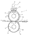
従来、画像形成装置において、記録材上に形成担持させた未定着トナー画像を永久固着画像として加熱定着する装置としては接触加熱型の装置が汎用されている。この接触加熱型の定着装置は、記録材に接触する表面の温度を所定の定着温度に加熱した回転部材(以下、定着ローラと記す)を記録材に対してニップ部にて接触させて、記録材上の未定着トナー画像を永久固着画像として加熱定着するものである。 Conventionally, in an image forming apparatus, a contact heating type apparatus has been widely used as an apparatus for heating and fixing an unfixed toner image formed and supported on a recording material as a permanently fixed image. In this contact heating type fixing device, a rotating member (hereinafter referred to as a fixing roller) whose surface temperature in contact with a recording material is heated to a predetermined fixing temperature is brought into contact with the recording material at a nip portion to perform recording. The unfixed toner image on the material is heat-fixed as a permanently fixed image.
定着ローラの加熱方式の一つとしては、内部加熱方式がある。これは、定着ローラの内部に加熱手段(加熱源:ヒータ等)を配設し、定着ローラを内側から加熱して定着ローラの表面を所定の定着温度に加熱するものである。しかし、内部加熱方式では、ローラ全体を加熱する必要があるため、オンデマンド性には劣る。 One heating system for the fixing roller is an internal heating system. In this method, heating means (heating source: heater or the like) is disposed inside the fixing roller, and the fixing roller is heated from the inside to heat the surface of the fixing roller to a predetermined fixing temperature. However, the internal heating method is inferior in on-demand because it is necessary to heat the entire roller.
オンデマンド性に対応するために、種々の検討がなされており、中でもフィルム加熱定着方式は有用な定着方式である。これは、フィルムを介してヒータを直接加熱する方式であるため、ヒータの熱を効率良く記録材に付与することが出来る。しかし、フィルム加熱定着はフィルムを使用するため、長期使用の際にフィルムが破れる、という不具合が生じることがある。 Various studies have been made in order to cope with the on-demand property, and the film heat fixing method is a useful fixing method. This is a system in which the heater is directly heated via a film, so that the heat of the heater can be efficiently applied to the recording material. However, since film heat fixing uses a film, there may be a problem that the film is broken during long-term use.
こうした懸念点を払拭する新たな定着方法として、外部加熱方式(表面加熱方式)が検討されている。 As a new fixing method to eliminate such concerns, an external heating method (surface heating method) has been studied.
外部加熱方式の装置は、セラミックヒータやハロゲンヒータを内蔵した小径の加熱ローラなどの低熱容量の加熱手段により定着ローラを外側より加熱するため、定着ローラの表面を急激に昇温させることが可能である。そのため、内部加熱方式の装置に比べてウォームアップ時間や、プリント信号を受信してから未定着トナー画像が形成された記録材を加熱定着するまでの時間(以後、ファーストプリントアウトタイムと記す)を短縮できる。それらに伴ってオンデマンド性も高まるため、好ましい。 In the external heating system, the surface of the fixing roller can be rapidly heated because the fixing roller is heated from the outside by a low heat capacity heating means such as a small diameter heating roller incorporating a ceramic heater or a halogen heater. is there. Therefore, the warm-up time compared to the internal heating system and the time from when a print signal is received until the recording material on which the unfixed toner image is formed is heated and fixed (hereinafter referred to as the first printout time). Can be shortened. Along with these, on-demand is also improved, which is preferable.
外部加熱方式に関する技術として、例えば定着ローラの内部を断熱化し、且つ最表層は熱伝導フィラーを導入することで高熱伝導化するものがある(特許文献1,2参照)。しかし、この技術によってウォームアップタイムの短縮がなされオンデマンド性は高まるものの、記録材の巻きつきや低温オフセットに対して、改善の余地を残している。 As a technique related to the external heating method, for example, there is a technique in which the inside of the fixing roller is thermally insulated and the outermost layer is made highly thermally conductive by introducing a heat conductive filler (see Patent Documents 1 and 2). However, although this technique shortens the warm-up time and increases the on-demand property, there is still room for improvement with respect to the winding of the recording material and the low temperature offset.
巻きつきや低温オフセットを改善するために、特許文献3では、表層に離型性の高いPFA(テトラフルオロエチレンとパーフルオロアルキルビニルエーテルとの共重合体)を配置し、用紙への粘着性を低下させる技術が開示されている。しかし、PFA層を有するために熱量の伝達効率が下がり、定着温度が高くなると共にオンデマンド性が劣るものとなるため、更なる改善の余地がある。 In order to improve wrapping and low temperature offset, in Patent Document 3, PFA (copolymer of tetrafluoroethylene and perfluoroalkyl vinyl ether) having high releasability is arranged on the surface layer to reduce the adhesiveness to paper. Techniques for making them disclosed are disclosed. However, since the PFA layer is provided, the heat transfer efficiency is lowered, the fixing temperature is increased, and the on-demand property is deteriorated, so there is room for further improvement.
したがって、更に低い温度での定着を可能にし、オンデマンド性を改善できる画像形成方法、および定着方法が求められている。 Accordingly, there is a need for an image forming method and a fixing method that enable fixing at a lower temperature and improve on-demand characteristics.
一方、従来からトナーの低温定着化については多くの検討がなされており、多官能エステルワックスを用いて低温定着性が改良できるとの報告がある(特許文献4、5、6参照)。また、スチレンに対する溶解度や分子量が規定された多官能エステルワックスを用いたトナーが提案されており、低温定着性に優れ、高解像度の画像を得ることができると報告されている(特許文献7、8参照)。さらに、2種のワックスを併用し低温定着性が改良できるとの報告もある(特許文献9、10、11参照)。
On the other hand, many studies have been made on the low-temperature fixing of toner, and it has been reported that the low-temperature fixing property can be improved by using a polyfunctional ester wax (see Patent Documents 4, 5, and 6). In addition, a toner using a polyfunctional ester wax having prescribed solubility and molecular weight in styrene has been proposed, and it has been reported that it has excellent low-temperature fixability and can obtain a high-resolution image (
しかしながら、このようなトナーを用いても、オンデマンド性、低温定着性、さらには耐巻きつき性について、まだまだ改良の余地があった。 However, even with such a toner, there is still room for improvement in terms of on-demand properties, low-temperature fixability, and wrapping resistance.
本発明の目的は、上記の如き問題点を解決した画像形成方法、定着方法、およびトナーを提供することにある。 An object of the present invention is to provide an image forming method, a fixing method, and a toner that solve the above problems.
従って、本発明の目的は優れた低温定着性、オンデマンド性、及び耐巻きつき性を達成できる画像形成方法、定着方法およびトナーを提供することである。 Accordingly, an object of the present invention is to provide an image forming method, a fixing method, and a toner that can achieve excellent low-temperature fixing property, on-demand property, and wrapping resistance.
本発明は、以下の構成の画像形成方法および定着方法に関する。 The present invention relates to an image forming method and fixing how the following configuration.
(1)静電潜像担持体を帯電手段により帯電する帯電工程、前記帯電された静電潜像担持体を露光して静電潜像を形成する露光工程、前記静電潜像をトナーで現像してトナー像を形成する現像工程、前記トナー像を中間転写体を介して、又は介さずに記録材へ転写する転写工程、前記トナー像を担持する記録材を加圧部材と回転可能な像加熱部材とで形成されるニップ部を通過させることにより加熱加圧定着する定着工程を有する画像形成方法において、
前記像加熱部材は内部に弾性層を有し、その外側に像加熱部材の単位面積あたりの熱容量が、100J/m2K以上600J/m2K以下の蓄熱層を有しており、
前記像加熱部材は、熱伝導率5.0W/mK以上の熱伝導フィラーを含有し、
前記熱伝導フィラーはAl及び/又はZn化合物であり、
前記像加熱部材の表面をEPMA(電子線マイクロアナライザー)により測定した際の前記熱伝導フィラーに由来するアルミニウム元素および/または亜鉛元素の割合が、EPMAで検出される全元素量に対して5.0質量%以上45.0質量%以下であり、
前記トナーは、結着樹脂、着色剤、エステル化合物、及び低融点物質を少なくとも有しており、
前記エステル化合物は4官能以上のエステル化合物であり、前記エステル化合物の融点をTm(A)、前記低融点物質の融点をTm(B)とすると、
Tm(B)≦Tm(A)+5℃
を満たすことを特徴とする画像形成方法。
(1) A charging step of charging the electrostatic latent image carrier with charging means, an exposure step of exposing the charged electrostatic latent image carrier to form an electrostatic latent image, and the electrostatic latent image with toner A development process for developing and forming a toner image, a transfer process for transferring the toner image to a recording material with or without an intermediate transfer member, and a recording material carrying the toner image can be rotated with a pressure member. In an image forming method including a fixing step of fixing by heating and pressing by passing a nip formed by an image heating member,
Said image heating member having an inner elastic layer, the heat capacity per unit area of the image heating member to the outside, has a 100 J / m 2 K or more 600 J / m 2 K or less of the heat storage layer,
The image heating member contains a heat conductive filler having a heat conductivity of 5.0 W / mK or more,
The thermally conductive filler is Al and / or Zn compound,
4. The ratio of the aluminum element and / or zinc element derived from the heat conductive filler when the surface of the image heating member is measured by EPMA (electron beam microanalyzer) is 5. 0 mass% or more and 45.0 mass% or less,
The toner has at least a binder resin, a colorant, an ester compound, and a low melting point substance,
The ester compound is a tetrafunctional or higher functional ester compound, and the melting point of the ester compound is Tm (A), and the melting point of the low melting point substance is Tm (B).
Tm (B) ≦ Tm (A) + 5 ° C
An image forming method characterized by satisfying the above.
(2)静電潜像担持体を帯電手段により帯電する帯電工程、前記帯電された静電潜像担持体を露光して静電潜像を形成する露光工程、前記静電潜像をトナーで現像してトナー像を形成する現像工程、前記トナー像を中間転写体を介して、又は介さずに記録材へ転写する転写工程、前記トナー像を担持する記録材を加圧部材と回転可能な像加熱部材とで形成されるニップ部を通過させることにより加熱加圧定着する定着工程を有する定着方法において、
前記像加熱部材は内部に弾性層を有し、その外側に像加熱部材の単位面積あたりの熱容量が、100J/m2K以上600J/m2K以下の蓄熱層を有しており、
前記像加熱部材は、熱伝導率5.0W/mK以上の熱伝導フィラーを含有し、
前記熱伝導フィラーはAl及び/又はZn化合物であり、
前記像加熱部材の表面をEPMA(電子線マイクロアナライザー)により測定した際の前記熱伝導フィラーに由来するアルミニウム元素および/または亜鉛元素の割合が、EPMAで検出される全元素量に対して5.0質量%以上45.0質量%以下であり、
前記トナーは、結着樹脂、着色剤、エステル化合物、及び低融点物質を少なくとも有しており、
前記エステル化合物は4官能以上のエステル化合物であり、前記エステル化合物の融点をTm(A)、前記低融点物質の融点をTm(B)とすると、
Tm(B)≦Tm(A)+5℃
を満たすことを特徴とする定着方法。
(2) a charging step of charging the electrostatic latent image carrier with charging means, an exposure step of exposing the charged electrostatic latent image carrier to form an electrostatic latent image, and the electrostatic latent image with toner A development process for developing and forming a toner image, a transfer process for transferring the toner image to a recording material with or without an intermediate transfer member, and a recording material carrying the toner image can be rotated with a pressure member. In a fixing method having a fixing step of fixing by heating and pressing by passing through a nip formed by an image heating member,
Said image heating member having an inner elastic layer, the heat capacity per unit area of the image heating member to the outside, has a 100 J / m 2 K or more 600 J / m 2 K or less of the heat storage layer,
The image heating member contains a heat conductive filler having a heat conductivity of 5.0 W / mK or more,
The thermally conductive filler is Al and / or Zn compound,
4. The ratio of the aluminum element and / or zinc element derived from the heat conductive filler when the surface of the image heating member is measured by EPMA (electron beam microanalyzer) is 5. 0 mass% or more and 45.0 mass% or less,
The toner has at least a binder resin, a colorant, an ester compound, and a low melting point substance,
The ester compound is a tetrafunctional or higher functional ester compound, and the melting point of the ester compound is Tm (A), and the melting point of the low melting point substance is Tm (B).
Tm (B) ≦ Tm (A) + 5 ° C
The fixing method characterized by satisfy | filling.
本発明によれば、低温定着性、オンデマンド性、及び耐巻きつき性に優れる画像形成方法、定着方法、およびトナーを提供出来る。 According to the present invention, it is possible to provide an image forming method, a fixing method, and a toner that are excellent in low-temperature fixing property, on-demand property, and wrapping resistance.
以下、本発明を詳細に説明する。 Hereinafter, the present invention will be described in detail.
本発明は、画像形成方法、定着方法及びトナーに関するものであり、像担持体を一様に帯電する帯電工程、帯電した像担持体を露光することで潜像を形成する潜像形成工程、静電潜像を現像してトナー画像を形成する現像工程、現像画像を記録材上に転写する転写工程に関しては、従来公知の電子写真プロセスが適用でき、特に限定されるものではない。 The present invention relates to an image forming method, a fixing method, and a toner, and includes a charging step for uniformly charging an image carrier, a latent image forming step for forming a latent image by exposing the charged image carrier, A conventionally known electrophotographic process can be applied to the developing process for developing the electrostatic latent image to form a toner image and the transferring process for transferring the developed image onto a recording material, and there is no particular limitation.
本発明の画像形成方法は、静電潜像担持体を帯電手段により帯電する帯電工程、前記帯電された静電潜像担持体を露光して静電潜像を形成する露光工程、前記静電潜像をトナーで現像してトナー像を形成する現像工程、前記トナー像を中間転写体を介して、又は介さずに記録材へ転写する転写工程、前記トナー像を担持する記録材を加圧部材と回転可能な像加熱部材とで形成されるニップ部を通過させることにより加熱加圧定着する定着工程を有する画像形成方法において、
前記像加熱部材は内部に弾性層を有し、その外側に像加熱部材の単位面積あたりの熱容量が、100J/m2K以上600J/m2K以下の蓄熱層を有しており、
前記像加熱部材は、熱伝導率5.0W/mK以上の熱伝導フィラーを含有し、
前記熱伝導フィラーはAl及び/又はZn化合物であり、
前記像加熱部材の表面をEPMA(電子線マイクロアナライザー)により測定した際の前記熱伝導フィラーに由来するアルミニウム元素および/または亜鉛元素の割合が、EPMAで検出される全元素量に対して5.0質量%以上45.0質量%以下であり、
前記トナーは、結着樹脂、着色剤、エステル化合物、及び低融点物質を少なくとも有しており、
前記エステル化合物は4官能以上のエステル化合物であり、前記エステル化合物の融点をTm(A)、前記低融点物質の融点をTm(B)とすると、
Tm(B)≦Tm(A)+5℃
を満たすことを特徴とする。
The image forming method of the present invention comprises a charging step of charging an electrostatic latent image carrier with a charging means, an exposure step of exposing the charged electrostatic latent image carrier to form an electrostatic latent image, and the electrostatic A development process for developing a latent image with toner to form a toner image, a transfer process for transferring the toner image to a recording material with or without an intermediate transfer member, and pressurizing the recording material carrying the toner image In an image forming method having a fixing step of fixing by heating and pressing by passing a nip formed by a member and a rotatable image heating member,
Said image heating member having an inner elastic layer, the heat capacity per unit area of the image heating member to the outside, has a 100 J / m 2 K or more 600 J / m 2 K or less of the heat storage layer,
The image heating member contains a heat conductive filler having a heat conductivity of 5.0 W / mK or more,
The thermally conductive filler is Al and / or Zn compound,
4. The ratio of the aluminum element and / or zinc element derived from the heat conductive filler when the surface of the image heating member is measured by EPMA (electron beam microanalyzer) is 5. 0 mass% or more and 45.0 mass% or less,
The toner has at least a binder resin, a colorant, an ester compound, and a low melting point substance,
The ester compound is a tetrafunctional or higher functional ester compound, and the melting point of the ester compound is Tm (A), and the melting point of the low melting point substance is Tm (B).
Tm (B) ≦ Tm (A) + 5 ° C
It is characterized by satisfying.
また本発明の定着方法は、静電潜像担持体を帯電手段により帯電する帯電工程、前記帯電された静電潜像担持体を露光して静電潜像を形成する露光工程、前記静電潜像をトナーで現像してトナー像を形成する現像工程、前記トナー像を中間転写体を介して、又は介さずに記録材へ転写する転写工程、前記トナー像を担持する記録材を加圧部材と回転可能な像加熱部材とで形成されるニップ部を通過させることにより加熱加圧定着する定着工程を有する定着方法において、
前記像加熱部材は内部に弾性層を有し、その外側に像加熱部材の単位面積あたりの熱容量が、100J/m2K以上600J/m2K以下の蓄熱層を有しており、
前記像加熱部材は、熱伝導率5.0W/mK以上の熱伝導フィラーを含有し、
前記熱伝導フィラーはAl及び/又はZn化合物であり、
前記像加熱部材の表面をEPMA(電子線マイクロアナライザー)により測定した際の前記熱伝導フィラーに由来するアルミニウム元素および/または亜鉛元素の割合が、EPMAで検出される全元素量に対して5.0質量%以上45.0質量%以下であり、
前記トナーは、結着樹脂、着色剤、エステル化合物、及び低融点物質を少なくとも有しており、
前記エステル化合物は4官能以上のエステル化合物であり、前記エステル化合物の融点をTm(A)、前記低融点物質の融点をTm(B)とすると、
Tm(B)≦Tm(A)+5℃
を満たすことを特徴とする。
The fixing method of the present invention includes a charging step of charging the electrostatic latent image carrier with a charging unit, an exposure step of exposing the charged electrostatic latent image carrier to form an electrostatic latent image, and the electrostatic A development process for developing a latent image with toner to form a toner image, a transfer process for transferring the toner image to a recording material with or without an intermediate transfer member, and pressurizing the recording material carrying the toner image In a fixing method including a fixing step of fixing by heating and pressing by passing a nip formed by a member and a rotatable image heating member,
Said image heating member having an inner elastic layer, the heat capacity per unit area of the image heating member to the outside, has a 100 J / m 2 K or more 600 J / m 2 K or less of the heat storage layer,
The image heating member contains a heat conductive filler having a heat conductivity of 5.0 W / mK or more,
The thermally conductive filler is Al and / or Zn compound,
4. The ratio of the aluminum element and / or zinc element derived from the heat conductive filler when the surface of the image heating member is measured by EPMA (electron beam microanalyzer) is 5. 0 mass% or more and 45.0 mass% or less,
The toner has at least a binder resin, a colorant, an ester compound, and a low melting point substance,
The ester compound is a tetrafunctional or higher functional ester compound, and the melting point of the ester compound is Tm (A), and the melting point of the low melting point substance is Tm (B).
Tm (B) ≦ Tm (A) + 5 ° C
It is characterized by satisfying.
また本発明のトナーは、静電潜像担持体を帯電手段により帯電する帯電工程、該帯電された静電潜像担持体を露光して静電潜像を形成する露光工程、該静電潜像をトナーで現像してトナー像を形成する現像工程、該トナー像を中間転写体を介して、又は介さずに記録材へ転写する転写工程、該トナー像を担持する記録材を加圧部材と回転可能な像加熱部材とで形成されるニップ部を通過させることにより加熱加圧定着する定着工程を有しており、
前記像加熱部材は内部に弾性層を有し、その外側に像加熱部材の単位面積あたりの熱容量が、100J/m2K以上600J/m2K以下の蓄熱層を有しており、
前記像加熱部材は、熱伝導率5.0W/mK以上の熱伝導フィラーを含有し、
前記熱伝導フィラーはAl及び/又はZn化合物であり、
前記像加熱部材の表面をEPMA(電子線マイクロアナライザー)により測定した際の前記熱伝導フィラーに由来するアルミニウム元素および/または亜鉛元素の割合が、EPMAで検出される全元素量に対して5.0質量%以上45.0質量%以下である画像形成方法に適応されるトナーであって、
前記トナーは、結着樹脂、着色剤、エステル化合物、及び低融点物質を少なくとも有しており、
前記エステル化合物は4官能以上のエステル化合物であり、前記エステル化合物の融点をTm(A)、前記低融点物質の融点をTm(B)とすると、
Tm(B)≦Tm(A)+5℃
を満たすことを特徴とする。
The toner of the present invention includes a charging step of charging the electrostatic latent image carrier with a charging unit, an exposure step of exposing the charged electrostatic latent image carrier to form an electrostatic latent image, and the electrostatic latent image. A development process for developing the image with toner to form a toner image, a transfer process for transferring the toner image to or through the intermediate transfer member, and a pressure member for the recording material carrying the toner image And a fixing step for fixing under heat and pressure by passing through a nip formed by a rotatable image heating member,
Said image heating member having an inner elastic layer, the heat capacity per unit area of the image heating member to the outside, has a 100 J / m 2 K or more 600 J / m 2 K or less of the heat storage layer,
The image heating member contains a heat conductive filler having a heat conductivity of 5.0 W / mK or more,
The thermally conductive filler is Al and / or Zn compound,
4. The ratio of the aluminum element and / or zinc element derived from the heat conductive filler when the surface of the image heating member is measured by EPMA (electron beam microanalyzer) is 5. A toner adapted to an image forming method of 0% by mass or more and 45.0% by mass or less,
The toner has at least a binder resin, a colorant, an ester compound, and a low melting point substance,
The ester compound is a tetrafunctional or higher functional ester compound, and the melting point of the ester compound is Tm (A), and the melting point of the low melting point substance is Tm (B).
Tm (B) ≦ Tm (A) + 5 ° C
It is characterized by satisfying.
本発明者らの検討によると、像加熱部材における蓄熱層は高い熱容量を持つと、定着時に記録材へ十分な熱量を付与出来るため、より低い温度での定着が可能になる。しかし、過剰な熱量はエネルギーロスに繋がってしまう。こうした熱量のロスも抑えつつ、十分な熱量を記録材へ付与するためには、蓄熱層の熱容量を高める必要があった。 According to the study by the present inventors, if the heat storage layer in the image heating member has a high heat capacity, a sufficient amount of heat can be applied to the recording material at the time of fixing, so that fixing at a lower temperature is possible. However, excessive heat leads to energy loss. In order to impart a sufficient amount of heat to the recording material while suppressing such heat loss, it is necessary to increase the heat capacity of the heat storage layer.
具体的には蓄熱層の熱容量を100J/m2K以上が必要であった。一方、熱容量が大きすぎると、像加熱部材表面の温度の上がり方が遅くなる。そのため、オンデマンド性に劣ると共に、定着に必要な熱量は増大してしまう。こうした弊害を無くすためには、蓄熱層の熱容量は600J/m2K以下とする必要があった。 Specifically, the heat capacity of the heat storage layer was required to be 100 J / m 2 K or more. On the other hand, if the heat capacity is too large, the temperature of the surface of the image heating member increases slowly. Therefore, the on-demand property is inferior and the amount of heat necessary for fixing increases. In order to eliminate such harmful effects, the heat capacity of the heat storage layer was required to be 600 J / m 2 K or less.
したがって、蓄熱層の熱量は100J/m2K以上600J/m2K以下とすることが重要である。 Therefore, heat of the heat storage layer is important to the 100 J / m 2 K or more 600 J / m 2 K or less.
熱容量が100J/m2K未満になると、放熱量が多くなると共に記録材に熱を奪われ易くなる。そのため、像加熱部材に付与する熱エネルギーは増大してしまう。600J/m2Kを超えると像加熱部材の温度上昇速度が低下し、ウォームアップタイムが延びるなどしてオンデマンド性に劣るため好ましくない。 When the heat capacity is less than 100 J / m 2 K, the amount of heat radiation increases and the recording material is easily deprived of heat. For this reason, the thermal energy applied to the image heating member increases. If it exceeds 600 J / m 2 K, the temperature increase rate of the image heating member is lowered, the warm-up time is extended, and the on-demand property is inferior.
効率的に蓄熱層の熱容量を100J/m2K以上600J/m2K以下にするためには、高い熱伝導率を有する熱伝導フィラーを含有する必要がある。 The heat capacity of efficiently heat storage layer to below 100 J / m 2 K or more 600 J / m 2 K, it is necessary to contain a thermally conductive filler having a high thermal conductivity.
具体的には熱伝導率5.0W/mK以上の熱伝導フィラーを含有している。5.0W/mK以上の熱伝導フィラーであると、効率的に蓄熱層に熱を伝えることができ、オンデマンド性、低温定着性が向上できる。 Specifically, it contains a heat conductive filler having a heat conductivity of 5.0 W / mK or more. When the heat conductive filler is 5.0 W / mK or more, heat can be efficiently transmitted to the heat storage layer, and on-demand properties and low-temperature fixability can be improved.
5.0W/mK未満であると熱伝達効率の低下に伴って熱量ロスが増大し、オンデマンド性が低下し、定着温度は高まってしまうため好ましくない。 If it is less than 5.0 W / mK, the heat loss increases with decreasing heat transfer efficiency, the on-demand property decreases, and the fixing temperature increases, which is not preferable.
本発明の熱伝導フィラーは、Al及び/又はZn化合物である。Al及び/又はZn化合物は、高い熱伝導性を有し、さらに蓄熱層中にて所望の分散状態が達成可能となるため、像加熱部材としてオンデマンド化、低温定着化が可能となる。 The heat conductive filler of the present invention is an Al and / or Zn compound. Since Al and / or Zn compounds have high thermal conductivity and can achieve a desired dispersed state in the heat storage layer, they can be on-demand and low-temperature fixed as an image heating member.
さらに、本発明者らが検討していく中で、像加熱部材の表面近傍のフィラーの存在状態を制御することで、飛躍的にオンデマンド化、低温定着化が図れることが分かった。つまり、蓄熱層中のフィラーの分散性に傾斜を持たせ、像加熱部材の表面近傍にフィラーを多く存在させるようにする。そうすることでヒータからの熱を効率良く蓄熱できるようになり、従来の像加熱部材に比べて熱応答性が大幅に向上し、オンデマンド性、低温定着性を良化することができる。 Furthermore, as the inventors studied, it was found that the on-demand and low-temperature fixing can be dramatically achieved by controlling the state of the filler in the vicinity of the surface of the image heating member. That is, the dispersibility of the filler in the heat storage layer is inclined so that a large amount of filler exists near the surface of the image heating member. By doing so, the heat from the heater can be efficiently stored, and the thermal responsiveness is greatly improved as compared with the conventional image heating member, and the on-demand property and the low-temperature fixability can be improved.
本発明者らは、熱応答性が向上し、オンデマンド性、低温定着性に優れた像加熱部材を得るためには、像加熱部材の表面をEPMA(電子線マイクロアナライザー)により測定した際の前記熱伝導フィラーに由来するアルミニウム元素および/または亜鉛元素の割合が、EPMAで検出される全元素量に対して5.0質量%以上45.0質量%以下にする必要があることを見出した。 In order to obtain an image heating member having improved thermal responsiveness and excellent on-demand properties and low-temperature fixability, the inventors have measured the surface of the image heating member with an EPMA (electron beam microanalyzer). It has been found that the proportion of the aluminum element and / or zinc element derived from the heat conductive filler must be 5.0% by mass or more and 45.0% by mass or less with respect to the total amount of elements detected by EPMA. .
本発明において、像加熱部材表面近傍のフィラーの検出方法としては、EPMAを用いた。EPMAは表面から数μmの深さまでに存在する元素を測定するものであり、検出されるAlやZn元素は表面から数μmまでの深さに存在する熱伝導フィラー量と対応する。本発明者らの検討によると、EPMA測定で検出されるAl及び/又はZnの存在割合が、検出される全元素量に対して5.0質量%以上45.0質量%以下であると、熱伝導率および熱応答性が向上し、オンデマンド性、低温定着性に効果が得られた。より好ましくは、10.0質量%以上40.0質量%以下であると、熱伝導率および熱応答性がさらに向上する。 In the present invention, EPMA is used as a method for detecting the filler near the surface of the image heating member. EPMA measures an element existing at a depth of several μm from the surface, and detected Al and Zn elements correspond to the amount of thermally conductive filler existing at a depth of several μm from the surface. According to the study by the present inventors, the presence ratio of Al and / or Zn detected by EPMA measurement is 5.0% by mass or more and 45.0% by mass or less with respect to the total amount of elements detected. The thermal conductivity and thermal responsiveness were improved, and an effect was obtained for on-demand and low-temperature fixability. More preferably, the thermal conductivity and thermal responsiveness are further improved when the content is 10.0% by mass or more and 40.0% by mass or less.
5.0質量%未満であると、像加熱部材表面近傍のフィラーが足りず、ヒータから受け取った熱量が像加熱部材に伝達されにくくなり、熱量のロスが生じるため、定着温度は上昇してしまう。一方、45.0質量%を超えると、熱伝導フィラー量が多いために像加熱部材とトナーとの付着力が高くなりすぎるため、トナーの巻きつき性が悪化してしまう。 If it is less than 5.0% by mass, the filler near the surface of the image heating member is insufficient, and the amount of heat received from the heater becomes difficult to be transmitted to the image heating member, resulting in loss of the amount of heat and the fixing temperature increases. . On the other hand, if it exceeds 45.0% by mass, the amount of the heat conductive filler is so large that the adhesive force between the image heating member and the toner becomes too high, so that the wrapping property of the toner is deteriorated.
以上のように、本発明の像加熱部材は、熱伝導率および熱応答性が良化し、オンデマンド性、および低温定着性を向上させることが可能となる。しかし、一方で像加熱部材の表面にトナーと親和性が高いフィラーが多数存在するために、トナーとの離型性が低下し、巻きつき性が悪くなる傾向もある。 As described above, the image heating member of the present invention has improved thermal conductivity and thermal responsiveness, and can improve on-demand properties and low-temperature fixability. However, on the other hand, since there are many fillers having high affinity with the toner on the surface of the image heating member, the releasability from the toner is lowered and the wrapping property tends to be deteriorated.
そこで本発明では、巻きつき性を改善し、且つ低温定着性を向上させるために、画像形成方法に用いるトナーについて種々の検討を行った。 Therefore, in the present invention, in order to improve the wrapping property and improve the low-temperature fixing property, various studies have been made on the toner used in the image forming method.
その結果、オンデマンド性、低温定着性、および耐巻きつき性を達成するためには、本発明の画像形成方法に適用されるトナーは、トナー中にエステル化合物と低融点物質を存在させ、双方の融点の関係を高度に制御することが重要であることが分かった。 As a result, in order to achieve on-demand properties, low-temperature fixability, and wrapping resistance, the toner applied to the image forming method of the present invention contains an ester compound and a low melting point substance in the toner, It was found that it is important to control the melting point relationship of the material to a high degree.
そうすることで、トナーとしてのシャープメルト性が非常に良好になり、低温定着性、および離型性が向上する。さらに、本発明の画像形成方法と組み合わさることで、トナーを急激に加熱できるようになり、像加熱部材またはトナー単独では得られないオンデマンド性、低温定着性、および耐巻きつき性が達成可能となり本発明に至った。 By doing so, the sharp melt property as a toner becomes very good, and the low-temperature fixability and the release property are improved. Furthermore, when combined with the image forming method of the present invention, the toner can be heated rapidly, and on-demand property, low-temperature fixing property, and wrapping resistance that cannot be obtained with an image heating member or toner alone can be achieved. It came to this invention.
本発明者らはこの理由について、以下のように考えている。トナーの可塑性と離型性が十分であった時、本発明のような像加熱部材の表面状態であると、染み出したワックス量と熱伝導フィラー量のバランスが取れているため離型性に関しては十分な性能を保持できる。また、ヒータより得た熱を効率的にトナーに伝えることが可能となると共に、トナーが熱を得てから変形する速度が非常に早くなる。そのため、それらの相乗効果によって、大幅に定着温度を下げることが可能になる。そうして、これまでにないオンデマンド性、低温定着性、および耐巻きつき性が達成可能となったものと考えている。 The present inventors consider this reason as follows. When the toner has sufficient plasticity and releasability, the surface state of the image heating member as in the present invention is balanced with respect to the amount of exuded wax and the amount of heat conductive filler. Can maintain sufficient performance. Further, the heat obtained from the heater can be efficiently transmitted to the toner, and the speed at which the toner is deformed after obtaining the heat becomes very fast. For this reason, the fixing temperature can be greatly lowered by their synergistic effect. Thus, it is considered that unprecedented on-demand, low-temperature fixability, and wrapping resistance can be achieved.
すなわち、本発明のトナーは、結着樹脂、着色剤、エステル化合物、及び低融点物質を少なくとも有するトナーであり、前記エステル化合物は4官能以上のエステル化合物であり、前記エステル化合物の融点をTm(A)、前記低融点物質の融点をTm(B)とするとTm(B)≦Tm(A)+5℃を満たすものである。 That is, the toner of the present invention is a toner having at least a binder resin, a colorant, an ester compound, and a low melting point substance, and the ester compound is a tetrafunctional or higher functional ester compound, and the melting point of the ester compound is Tm ( A) When the melting point of the low melting point substance is Tm (B), Tm (B) ≦ Tm (A) + 5 ° C. is satisfied.
一般的に、溶融定着において低温定着性をトナーで改良するためには、トナーの結着樹脂のガラス転移温度を低くする。もしくは、低融点物質(いわゆるワックス)を添加する等により設計される。しかし、本発明者らが従来製法により、低融点物質を添加した低いガラス転移温度を有するトナーを作製し、本発明を構成している外部加熱定着装置を用いて検討したところ、確かに定着開始温度が下がる兆候は認められたが、加熱部材の蓄えている熱により低融点物質が結着樹脂に染み込み、トナーの溶融粘度が低くなるためか、記録材が定着部材に巻きつく現象が生じ、定着可能な温度領域を殆ど有さない結果となった。 Generally, in order to improve low-temperature fixability with a toner in melt fixing, the glass transition temperature of the binder resin of the toner is lowered. Or it is designed by adding a low melting point substance (so-called wax). However, when the present inventors made a toner having a low glass transition temperature to which a low-melting-point substance was added by a conventional manufacturing method and examined it using an external heating fixing device constituting the present invention, it was confirmed that fixing was started. Although signs of a decrease in temperature were observed, the low melting point material soaks into the binder resin due to the heat stored in the heating member, and the phenomenon that the recording material wraps around the fixing member occurs because the melt viscosity of the toner decreases. As a result, there was almost no temperature range capable of fixing.
上記問題を克服するために、本発明者らがさらに検討した結果、トナーの結着樹脂、4官能以上のエステル化合物、及び低融点物質の関係をコントロールすることで離型性に優れ、長期の使用においても高い画像濃度を得ることができ、さらに、低温定着性に優れ、像加熱装置のウォームアップタイムやファーストプリントアウトタイムを短縮し、消費電力が低減することができることが判明し、本発明に至った。 As a result of further studies by the present inventors to overcome the above problems, it is possible to control the relationship between the binder resin of the toner, the tetrafunctional or higher ester compound, and the low melting point material, thereby providing excellent releasability and long-term performance. It has been found that a high image density can be obtained even in use, excellent in low-temperature fixability, the warm-up time and first printout time of the image heating apparatus can be shortened, and the power consumption can be reduced. It came to.
まず、本発明に用いるエステル化合物であるが、4官能以上のエステル化合物であることから分子構造が嵩高い。このため、定着時に熱を受けて溶融しても結着樹脂中に染み込み難く、トナー表面に染み出しにくい傾向にある。よって、このようなエステル化合物を単独で用いた場合、充分な離型効果を得られずに良好な定着性は得られない。 First, although it is an ester compound used for this invention, since it is a tetrafunctional or more ester compound, its molecular structure is bulky. For this reason, even if it is melted by receiving heat during fixing, it does not easily soak into the binder resin, and tends not to penetrate the toner surface. Therefore, when such an ester compound is used alone, a sufficient releasing effect cannot be obtained, and good fixability cannot be obtained.
しかし、このようなエステル化合物とTm(B)≦Tm(A)+5℃の関係を満たす低融点物質を併用した場合、低温定着性、離型性は非常に良好なものとなる。この理由であるが、本発明者らは以下のように考えている。 However, when such an ester compound and a low melting point material satisfying the relationship of Tm (B) ≦ Tm (A) + 5 ° C. are used in combination, the low-temperature fixability and releasability are very good. For this reason, the present inventors consider as follows.
上記の如き、本発明に用いるエステル化合物は定着時に熱を受けて溶融しても結着樹脂に染み込まない。しかし、溶融しても結着樹脂に染み込まないと言うことは、トナー中で液芯構造に近い状態になっていると考えられる。このような場合、エステル化合物はトナーの外に染み出さないために離型性が悪いものの、トナーは定着時に圧を受けることにより非常に変形し易い状態であると考えられる。 As described above, the ester compound used in the present invention does not soak into the binder resin even when melted by receiving heat during fixing. However, the fact that it does not penetrate into the binder resin even when melted is considered to be in a state close to the liquid core structure in the toner. In such a case, the ester compound does not bleed out of the toner, and thus the releasability is poor. However, the toner is considered to be in a state of being very easily deformed by receiving pressure during fixing.
また、本発明のエステル化合物は嵩高い故に溶融すると体積膨張が他の化合物よりも大きいと考えられる。 Further, since the ester compound of the present invention is bulky, it is considered that when it is melted, the volume expansion is larger than that of other compounds.
一方、本発明においてはTm(B)≦Tm(A)+5℃の関係を満たす低融点物質(いわゆるワックス)も用いることが必須であるが、このような低融点物質とエステル化合物を併用する事によりはじめて非常に良好な低温定着性を達成できる。 On the other hand, in the present invention, it is essential to use a low-melting substance (so-called wax) that satisfies the relationship of Tm (B) ≦ Tm (A) + 5 ° C. However, such a low-melting substance and an ester compound must be used in combination. For the first time, very good low-temperature fixability can be achieved.
これはエステル化合物と低融点物質の融点が近い(もしくは低融点物質の融点が低い)ため、低融点物質が溶融したところにエステル化合物が溶融し、低融点物質を押し出すために良好な離型性を得ることができ、離型性がよくなることで定着部材とトナーが接触する時間が一定になり易く、濃度ムラが発生しにくくなり、また記録材が定着部材に巻きつきにくくなる。さらに、エステル化合物は結着樹脂に染み込まないために液芯構造に近い状態となり、定着時の圧を受けることによりトナーが変形し、メディアとのアンカーリングも良好に行われると考えられる。 This is because the melting point of the low melting point material is close to that of the ester compound (or the low melting point of the low melting point material), so that the ester compound melts and extrudes the low melting point material when the low melting point material melts. Since the releasability is improved, the contact time between the fixing member and the toner tends to be constant, density unevenness is less likely to occur, and the recording material is less likely to wind around the fixing member. Further, since the ester compound does not soak into the binder resin, it becomes a state close to a liquid core structure, and it is considered that the toner is deformed by receiving a pressure at the time of fixing, and anchoring with the medium is performed well.
よって、良好な離型性とメディアへのアンカーリングの両者の効果により非常に良好な低温定着性を得ることが可能となると、本発明者らは考えている。 Therefore, the present inventors consider that very good low-temperature fixability can be obtained by the effects of both good releasability and anchoring to the media.
また、本発明の如きエステル化合物は結晶化度が高く、シャープメルト性も高いことから離型性の低い像加熱部材においても適応性が高く、オンデマンド定着器にも好適に用いることができる。 In addition, since the ester compound of the present invention has a high crystallinity and a high sharp melt property, it is highly adaptable to an image heating member having a low releasability and can be suitably used for an on-demand fixing device.
このような理由から、本発明のトナーは低融点物質と4官能以上のエステル化合物を含有しており、前記エステル化合物の融点をTm(A)、前記低融点物質の融点をTm(B)とすると、Tm(B)≦Tm(A)+5℃を満たすことが重要である。 For this reason, the toner of the present invention contains a low melting point substance and a tetrafunctional or higher functional ester compound. The melting point of the ester compound is Tm (A), and the melting point of the low melting point substance is Tm (B). Then, it is important to satisfy Tm (B) ≦ Tm (A) + 5 ° C.
また、本発明のエステル化合物がモノエステルやグリセリン、エリスリトール等の官能基数が少ないエステル化合物を用いた場合、樹脂への染み込みが生じやすくなり、上述の効果が得られにくく、定着性が劣るものとなる。 In addition, when the ester compound of the present invention uses an ester compound with a small number of functional groups such as monoester, glycerin, erythritol, it is likely to penetrate into the resin, the above-mentioned effects are difficult to obtain, and the fixing property is inferior. Become.
次に、低融点物質であるが、融点がエステル化合物の融点よりも5℃以上高い場合、エステル化合物による押し出し効果が充分に得られにくく、良好な定着性が得られない。 Next, although it is a low melting point substance, when the melting point is higher by 5 ° C. or more than the melting point of the ester compound, the extrusion effect by the ester compound is hardly obtained, and good fixability cannot be obtained.
このような理由から、低融点物質の融点はTm(B)≦Tm(A)+5℃を満たすことが必須であり、より好ましくはTm(B)≦Tm(A)である。 For these reasons, it is essential that the melting point of the low melting point substance satisfy Tm (B) ≦ Tm (A) + 5 ° C., and more preferably Tm (B) ≦ Tm (A).
本発明に用いるエステル化合物は、スチレン−アクリル樹脂への溶解度S(A)が2.5%以下であることが好ましく、より好ましくは1.0%以下である。スチレン−アクリル樹脂への溶解度S(A)が2.5%以下であると、定着時に樹脂への染み込みがより生じ難くなり、定着性がより良好なものとなり好ましい。 The ester compound used in the present invention preferably has a solubility S (A) in a styrene-acrylic resin of 2.5% or less, more preferably 1.0% or less. When the solubility S (A) in the styrene-acrylic resin is 2.5% or less, the penetration into the resin is less likely to occur at the time of fixing, and the fixing property is more preferable.
スチレン−アクリル樹脂への溶解度S(A)は用いるカルボン酸の炭素数やエステル結合数等にて調整可能である。 The solubility S (A) in the styrene-acrylic resin can be adjusted by the number of carbons and the number of ester bonds of the carboxylic acid used.
本発明に用いるエステル化合物の40℃におけるスチレンモノマーに対する溶解度は5.0%未満であると、上記効果が顕著となり、更に好ましい。また、本トナーの製造に好適な懸濁重合法においてトナーを製造する場合、モノマーに対する溶解度が5.0%未満であると重合中に析出し易く、トナー中でコアを形成しやすいと考えられる。本発明においてエステル化合物の役割は上述の如きであり、トナー中ではしっかりしたコアを形成している方が効果としては大きく、定着性は良好なものとなると考えられる。よって、エステル化合物の40℃におけるスチレンモノマーに対する溶解度は5.0%未満であることが好ましい。 When the ester compound used in the present invention has a solubility in a styrene monomer at 40 ° C. of less than 5.0%, the above-described effect becomes remarkable, and it is more preferable. Further, when the toner is produced by a suspension polymerization method suitable for the production of the present toner, it is considered that if the solubility in the monomer is less than 5.0%, it is likely to be precipitated during the polymerization and a core is easily formed in the toner. . In the present invention, the role of the ester compound is as described above. It is considered that the formation of a solid core in the toner is more effective and the fixing property is better. Therefore, it is preferable that the solubility with respect to the styrene monomer in 40 degreeC of an ester compound is less than 5.0%.
本発明に用いる低融点物質はTm(B)≦Tm(A)+5℃の関係を満たす全ての公知のワックスを用いることが可能であるが、低融点物質のスチレン−アクリル樹脂への溶解度S(B)は1.5%以上6.0%以下であり、S(A)<S(B)であることが好ましい。 As the low melting point material used in the present invention, all known waxes satisfying the relationship of Tm (B) ≦ Tm (A) + 5 ° C. can be used, but the solubility S ( B) is 1.5% to 6.0%, and preferably S (A) <S (B).
この理由であるが、上述の如き、低融点物質は結着樹脂に染み込み、トナーの外部に染み出すことで定着性が良好なものとなる。このため、低融点物質のスチレン−アクリル樹脂への溶解度S(B)が1.5%以上であると、トナー外部への染み出し量が充分となり、良好な定着性が得られやすくなる。一方、低融点物質のスチレン−アクリル樹脂への溶解度S(B)が6.0%以下であるとトナー表面へのマイグレーション等が生じにくくなり、保存安定性が向上する。 For this reason, as described above, the low-melting-point substance soaks into the binder resin and exudes to the outside of the toner, so that the fixing property is good. For this reason, when the solubility S (B) of the low-melting-point substance in the styrene-acrylic resin is 1.5% or more, the amount of seepage to the outside of the toner is sufficient, and good fixability is easily obtained. On the other hand, when the solubility S (B) of the low-melting-point substance in the styrene-acrylic resin is 6.0% or less, migration to the toner surface is difficult to occur, and storage stability is improved.
また、S(A)<S(B)であると、エステル化合物の押し出し効果がより顕著に発揮されるため、定着時に離型性が向上し好ましい。 Further, it is preferable that S (A) <S (B) because the extrusion effect of the ester compound is more remarkably exhibited, so that the releasability is improved during fixing.
本発明に用いるエステル化合物はトナーの樹脂成分100質量部あたり2.0質量部以上20.0質量部以下であることが好ましい。 The ester compound used in the present invention is preferably 2.0 parts by mass or more and 20.0 parts by mass or less per 100 parts by mass of the resin component of the toner.
エステル化合物が2.0質量部以上であると、低融点物質の押し出し効果や液芯構造によるトナーの変形が促進されやすくなる。 When the ester compound is 2.0 parts by mass or more, the extrusion effect of the low melting point substance and the deformation of the toner due to the liquid core structure are easily promoted.
一方、エステル化合物の量が20.0質量部以下であると、エステル化合物の分散性が向上し現像性が良化する傾向にある。 On the other hand, when the amount of the ester compound is 20.0 parts by mass or less, the dispersibility of the ester compound is improved and the developability tends to be improved.
また、本発明に用いる低融点物質の含有量は、エステル化合物の含有量に対し1.0から5.0倍であると低融点物質が効率的に染み出しやすくなり、良好な定着性を得ることが出来、好ましい。 Further, when the content of the low-melting-point substance used in the present invention is 1.0 to 5.0 times the content of the ester compound, the low-melting-point substance easily oozes out and obtains good fixability. It is possible and preferable.
本発明に用いるエステル化合物の融点は70℃から90℃であることが好ましい。エステル化合物の融点が70℃以上であると、結着樹脂へ染み込みにくくなるため、良好な定着性が得られ易くなる。 The melting point of the ester compound used in the present invention is preferably 70 ° C to 90 ° C. When the melting point of the ester compound is 70 ° C. or higher, it becomes difficult to soak into the binder resin, so that good fixability is easily obtained.
一方、エステル化合物の融点が90℃以下であると、トナー中での分散性が向上しやすくなり、良好な定着性が得られ易い。 On the other hand, when the melting point of the ester compound is 90 ° C. or less, the dispersibility in the toner is easily improved, and good fixability is easily obtained.
本発明に用いるエステル化合物の分子量は1000以上2500以下であることが好ましい。エステル化合物の分子量が1000以上であると結着樹脂に染み込みにくくなり易く、本発明の効果を発揮し易くなる。また、エステル化合物の分子量が2500以下であるとシャープメルト性が向上しやすくなる。 The molecular weight of the ester compound used in the present invention is preferably 1000 or more and 2500 or less. If the molecular weight of the ester compound is 1000 or more, it will be difficult to soak into the binder resin, and the effects of the present invention will be easily exhibited. Further, when the molecular weight of the ester compound is 2500 or less, the sharp melt property is easily improved.
本発明のトナーは、高画質化を達成すべくより微小な潜像ドットを忠実に現像するために、トナーの重量平均粒径(D4)は3μm以上12μm以下であることが好ましく、より好ましくは4μm以上9μm以下である。トナーの重量平均粒径(D4)が3μm以上であると、現像器内での規制がしやすくなり、均一な帯電性を得やすくなる。また、トナーの重量平均粒径(D4)が12μm以下であるとドット再現性が向上しやすくなり、高精細な画像が得られ易くなる。 The toner of the present invention preferably has a weight average particle diameter (D4) of 3 μm or more and 12 μm or less in order to faithfully develop finer latent image dots in order to achieve high image quality. 4 μm or more and 9 μm or less. When the weight average particle diameter (D4) of the toner is 3 μm or more, it is easy to regulate in the developing device, and uniform chargeability is easily obtained. Further, when the weight average particle diameter (D4) of the toner is 12 μm or less, the dot reproducibility is easily improved and a high-definition image is easily obtained.
本発明のトナーは平均円形度が0.950以上であることが好ましい。トナーの平均円形度が0.950以上ではトナーの形状は球形又はこれに近い形になり、流動性に優れ均一な摩擦帯電性を得られやすく、高精細な画像が得られる。また、トナーの円形度分布において、モード円形度が0.98以上であると上記作用がより一層顕著になり、より好ましい。 The toner of the present invention preferably has an average circularity of 0.950 or more. When the average circularity of the toner is 0.950 or more, the shape of the toner is a sphere or a shape close thereto, and it is easy to obtain a uniform triboelectric chargeability with excellent fluidity, and a high-definition image can be obtained. In the circularity distribution of the toner, when the mode circularity is 0.98 or more, the above action becomes more remarkable, which is more preferable.
本発明のトナーは、トナーのテトラヒドロフラン(THF)可溶分のゲルパーミエーションクロマトグラフィー(GPC)により測定した分子量分布において、分子量10000から40000の範囲にメインピークのピークットップを有することが好ましい。さらに12000から30000の範囲の範囲に上記ピークトップを有することがより好ましい。ピークトップが10000以上であると、保存安定性が向上しやすくなる。また、ピークトップが40000以下であると、低温定着性が向上しやすくなる。 The toner of the present invention preferably has a main peak in the molecular weight range of 10,000 to 40,000 in the molecular weight distribution measured by gel permeation chromatography (GPC) of the tetrahydrofuran (THF) soluble content of the toner. Furthermore, it is more preferable to have the peak top in the range of 12000 to 30000. When the peak top is 10,000 or more, the storage stability is easily improved. Further, when the peak top is 40000 or less, the low-temperature fixability is easily improved.
本発明のトナーは樹脂成分のTHF不溶分を有し、樹脂成分100質量部に対しTHF不溶分は5.0質量%以上65.0質量%以下であることが好ましい。トナー中にTHF不溶分が存在することによりトナーの強度が増し、長期使用においてトナー劣化が生じ難く、長期使用においても高精彩な画像を得ることができる。 The toner of the present invention has a THF insoluble content of the resin component, and the THF insoluble content is preferably 5.0% by mass or more and 65.0% by mass or less with respect to 100 parts by mass of the resin component. The presence of the THF-insoluble component in the toner increases the strength of the toner, so that toner deterioration hardly occurs during long-term use, and a high-definition image can be obtained even during long-term use.
また、定着時にトナーは定着器から受けた熱により溶融するが、THF不溶分を5.0質量%以上65.0質量%以下有することで溶融時でも適度な粘弾性を有することが可能となる。このため、定着時においても定着部材への巻きつきが生じにくくなり好ましい。 In addition, the toner is melted by the heat received from the fixing device at the time of fixing, but by having a THF insoluble content of 5.0% by mass or more and 65.0% by mass or less, it becomes possible to have an appropriate viscoelasticity even at the time of melting. . For this reason, it is preferable that winding around the fixing member hardly occurs even during fixing.
なお、トナーの樹脂成分のTHF不溶分の測定は以下のようにして行うことが可能である。トナー1gを精秤して円筒ろ紙に仕込み、THF200mlにて20時間ソックスレー抽出する。その後円筒ろ紙を取り出し、40℃で20時間真空乾燥して残渣質量を測定し、下式より算出する。なお、トナーの樹脂成分とは、トナーから荷電制御剤、離型剤成分、外添剤、顔料、磁性体を除いた成分である。THF不溶分の測定時には、これらの含有物がTHFに可溶か不溶かを考慮して、樹脂成分を基準としたTHF不溶分を算出する。
THF不溶分(%)=(W2−W3)/(W1−W3−W4)×100
The THF insoluble content of the resin component of the toner can be measured as follows. 1 g of toner is precisely weighed and charged in a cylindrical filter paper, and extracted with 200 ml of THF for 20 hours with Soxhlet. Thereafter, the cylindrical filter paper is taken out, vacuum-dried at 40 ° C. for 20 hours, the residue mass is measured, and calculated from the following formula. The resin component of the toner is a component obtained by removing the charge control agent, the release agent component, the external additive, the pigment, and the magnetic material from the toner. At the time of measuring the THF-insoluble content, the THF-insoluble content based on the resin component is calculated in consideration of whether these contents are soluble or insoluble in THF.
THF insoluble content (%) = (W2-W3) / (W1-W3-W4) × 100
ここで、W1はトナーの質量、W2は残渣質量、W3はトナーの樹脂成分以外のTHFに不溶な成分の質量、W4はトナーの樹脂成分以外のTHFに可溶な成分の質量である。 Here, W1 is the mass of the toner, W2 is the mass of the residue, W3 is the mass of a component insoluble in THF other than the resin component of the toner, and W4 is the mass of a component soluble in THF other than the resin component of the toner.
トナーの樹脂成分のTHF不溶分は、用いる開始剤、架橋剤の種類、量等の組み合わせにより、任意に変えることが可能である。また、連鎖移動剤等を使用しても調整可能である。 The THF insoluble content of the resin component of the toner can be arbitrarily changed depending on the combination of the initiator used, the type and amount of the crosslinking agent, and the like. It can also be adjusted by using a chain transfer agent or the like.
本発明に用いるエステル化合物は4官能以上のアルコール成分とカルボン酸成分から形成されている。4官能以上のアルコール成分としてペンタエリスリトール、ジペンタエリスリトール、トリペンタエリスリトール、ペンタグリセロール等が用いられ、これらの中でもペンタエリスリトール、ジペンタエリスリトールがより好ましく用いられる。
カルボン酸成分としては、ウンデカン酸、ラウリン酸、ミリスチン酸、パルミチン酸、ステアリン酸、ノナデカン酸、アラキジン酸、ベヘン酸、リグノセリン酸、セロチン酸または更に長鎖のアルキル基を有する長鎖アルキルカルボン酸類の如き飽和脂肪酸;ブラシジン酸、エレオステアリン酸、バリナリン酸の如き不飽和脂肪酸が用いられる。これらの中でもアラキジン酸、ベヘン酸がより好ましく用いられる。
The ester compound used in the present invention is formed from a tetrafunctional or higher functional alcohol component and a carboxylic acid component. As the tetrafunctional or higher functional alcohol component, pentaerythritol, dipentaerythritol, tripentaerythritol, pentaglycerol and the like are used, and among these, pentaerythritol and dipentaerythritol are more preferably used.
Examples of the carboxylic acid component include undecanoic acid, lauric acid, myristic acid, palmitic acid, stearic acid, nonadecanoic acid, arachidic acid, behenic acid, lignoceric acid, serotic acid, and long-chain alkyl carboxylic acids having a long-chain alkyl group. Saturated fatty acids such as: unsaturated fatty acids such as brassic acid, eleostearic acid, and valinal acid are used. Among these, arachidic acid and behenic acid are more preferably used.
本発明のエステル化合物の水酸基価は10mgKOH/g以下であり、酸価は10mgKOH/g以下である事が好ましい。 The ester compound of the present invention preferably has a hydroxyl value of 10 mgKOH / g or less and an acid value of 10 mgKOH / g or less.
水酸基価が10mgKOH/g以下であると、長期保存においてトナー表面へのマイグレーションが起こり難いため好ましい。 A hydroxyl value of 10 mgKOH / g or less is preferable because migration to the toner surface hardly occurs during long-term storage.
また、酸価が10mgKOH/g以下であると、トナーの帯電量が安定し易くなる。 Further, when the acid value is 10 mgKOH / g or less, the charge amount of the toner is easily stabilized.
本発明に用いる低融点物質はTm(B)≦Tm(A)+5℃の関係を満たす公知のワックスを使用できる。具体的には、パラフィンワックス、マイクロクリスタリンワックス、ペトロラクタム等の石油系ワックス及びその誘導体;モンタンワックスおよびその誘導体;フィッシャートロプシュ法による炭化水素ワックス及びその誘導体;ポリエチレンに代表されるポリオレフィンワックス及びその誘導体;カルナバワックス、キャンデリラワックス等天然ワックス及びその誘導体などである。ここで、誘導体は酸化物や、ビニル系モノマーとのブロック共重合物、グラフト変性物を含む。更には、高級脂肪族アルコール、ステアリン酸、パルミチン酸等の脂肪酸及びその化合物;酸アミドワックス、エステルワックス、ケトン、硬化ヒマシ油及びその誘導体;植物系ワックス;動物性ワックスなども使用できる。これら本発明に用いる低融点物質の種類は1種でもよく、複数種を併用しても良い。 As the low melting point substance used in the present invention, a known wax satisfying the relationship of Tm (B) ≦ Tm (A) + 5 ° C. can be used. Specifically, petroleum waxes such as paraffin wax, microcrystalline wax, petrolactam and derivatives thereof; montan wax and derivatives thereof; hydrocarbon waxes and derivatives thereof by Fischer-Tropsch method; polyolefin waxes and derivatives thereof typified by polyethylene Natural waxes such as carnauba wax and candelilla wax and derivatives thereof; Here, the derivatives include oxides, block copolymers with vinyl monomers, and graft modified products. Furthermore, fatty acids such as higher aliphatic alcohols, stearic acid and palmitic acid and compounds thereof; acid amide waxes, ester waxes, ketones, hydrogenated castor oil and derivatives thereof; plant waxes; animal waxes and the like can also be used. These low melting point substances used in the present invention may be one kind or a plurality of kinds may be used in combination.
本発明のトナーに用いられる結着樹脂としては、ポリスチレン、ポリビニルトルエンなどのスチレン及びその置換体の単重合体;スチレン−プロピレン共重合体、スチレン−ビニルトルエン共重合体、スチレン−ビニルナフタリン共重合体、スチレン−アクリル酸メチル共重合体、スチレン−アクリル酸エチル共重合体、スチレン−アクリル酸ブチル共重合体、スチレン−アクリル酸オクチル共重合体、スチレン−アクリル酸ジメチルアミノエチル共重合体、スチレン−メタアクリル酸メチル共重合体、スチレン−メタアクリル酸エチル共重合体、スチレン−メタアクリル酸ブチル共重合体、スチレン−メタクリル酸ジメチルアミノエチル共重合体、スチレン−ビニルメチルエーテル共重合体、スチレン−ビニルエチルエーテル共重合体、スチレン−ビニルメチルケトン共重合体、スチレン−ブタジエン共重合体、スチレン−イソプレン共重合体、スチレン−マレイン酸共重合体、スチレン−マレイン酸エステル共重合体などのスチレン系共重合体;ポリメチルメタクリレート、ポリブチルメタクリレート、ポリ酢酸ビニル、ポリエチレン、ポリプロピレン、ポリビニルブチラール、シリコーン樹脂、ポリエステル樹脂、ポリアミド樹脂、エポキシ樹脂、ポリアクリル酸樹脂を用いることができ、これらは単独で又は複数種を組み合わせて用いることができる。この中でも特にスチレン系共重合体及びポリエステル樹脂が現像特性、定着性等の点で好ましい。 Examples of the binder resin used in the toner of the present invention include styrene such as polystyrene and polyvinyltoluene, and homopolymers of substitution products thereof; styrene-propylene copolymer, styrene-vinyltoluene copolymer, styrene-vinylnaphthalene copolymer. Polymer, styrene-methyl acrylate copolymer, styrene-ethyl acrylate copolymer, styrene-butyl acrylate copolymer, styrene-octyl acrylate copolymer, styrene-dimethylaminoethyl acrylate copolymer, styrene -Methyl methacrylate copolymer, styrene-ethyl methacrylate copolymer, styrene-butyl methacrylate copolymer, styrene-dimethylaminoethyl methacrylate copolymer, styrene-vinyl methyl ether copolymer, styrene -Vinyl ethyl ether copolymer, Styrene copolymers such as lene-vinyl methyl ketone copolymer, styrene-butadiene copolymer, styrene-isoprene copolymer, styrene-maleic acid copolymer, styrene-maleic acid ester copolymer; polymethyl methacrylate , Polybutyl methacrylate, polyvinyl acetate, polyethylene, polypropylene, polyvinyl butyral, silicone resin, polyester resin, polyamide resin, epoxy resin, polyacrylic acid resin can be used, and these can be used alone or in combination. Can do. Of these, styrene copolymers and polyester resins are particularly preferred from the standpoints of development characteristics and fixability.
本発明のトナーには、帯電特性向上のために必要に応じて荷電制御剤を配合しても良い。荷電制御剤としては、公知のものが利用できるが、帯電スピードが速く、且つ一定の帯電量を安定して維持できる荷電制御剤が特に好ましい。更に、トナーを後述するような重合法を用いて製造する場合には、重合阻害性が低く、水系分散媒体への可溶化物が実質的にない荷電制御剤が特に好ましい。荷電制御剤のうち、ネガ系荷電制御剤として具体的な化合物として、サリチル酸、アルキルサリチル酸、ジアルキルサリチル酸、ナフトエ酸、ダイカルボン酸などの芳香族カルボン酸の金属化合物;アゾ染料又はアゾ顔料の金属塩又は金属錯体;スルフォン酸又はカルボン酸基を側鎖に持つ高分子型化合物;ホウ素化合物;尿素化合物;ケイ素化合物;カリックスアレーン等が挙げられる。ポジ系荷電制御剤としては、四級アンモニウム塩、該四級アンモニウム塩を側鎖に有する高分子型化合物、グアニジン化合物、ニグロシン系化合物、イミダゾール化合物等が挙げられる。 In the toner of the present invention, a charge control agent may be blended as necessary to improve charging characteristics. As the charge control agent, a known one can be used, but a charge control agent that has a high charging speed and can stably maintain a constant charge amount is particularly preferable. Further, when the toner is produced using a polymerization method as described later, a charge control agent having a low polymerization inhibition property and substantially free from a solubilized product in an aqueous dispersion medium is particularly preferable. Among the charge control agents, specific compounds as negative charge control agents include metal compounds of aromatic carboxylic acids such as salicylic acid, alkylsalicylic acid, dialkylsalicylic acid, naphthoic acid, dicarboxylic acid; metal salts of azo dyes or azo pigments Or a metal complex; a polymer compound having a sulfonic acid or carboxylic acid group in the side chain; a boron compound; a urea compound; a silicon compound; and a calixarene. Examples of the positive charge control agent include a quaternary ammonium salt, a polymer compound having the quaternary ammonium salt in the side chain, a guanidine compound, a nigrosine compound, and an imidazole compound.
荷電制御剤をトナーに含有させる方法としては、トナー粒子内部に添加する方法と、懸濁重合によりトナーの製造を行う場合には、造粒前に重合性単量体組成物中に荷電制御剤を添加する方法が一般的である。また、水中で油液滴を形成し重合を行っている最中、又は重合後に荷電制御剤を溶解、懸濁させた重合性単量体を加えることによりシード重合を行い、トナー表面を均一に覆うことも可能である。また、荷電制御剤として有機金属化合物を用いる場合は、トナー粒子にこれら化合物を添加し、シェアをかけ混合・撹拌することにより導入することも可能である。 As a method for adding a charge control agent to the toner, a method of adding the charge control agent to the inside of the toner particles, and in the case of producing the toner by suspension polymerization, the charge control agent is added to the polymerizable monomer composition before granulation. A method of adding is generally used. Also, during the polymerization by forming oil droplets in water, or after polymerization, seed polymerization is carried out by adding a polymerizable monomer in which the charge control agent is dissolved and suspended, and the toner surface is made uniform. It is also possible to cover. In the case where an organometallic compound is used as the charge control agent, it is also possible to introduce the compound by adding these compounds to the toner particles, and applying a shear and mixing and stirring.
これらの荷電制御剤の使用量は、結着樹脂の種類、他の添加剤の有無、分散方法を含めたトナー製造方法によって決定されるものであり一義的に限定されるものではない。しかし、トナー粒子に内部添加する場合、好ましくは結着樹脂100質量部に対して0.1から10質量部、より好ましくは0.1から5質量部の範囲で用いられる。また、トナー粒子に外部添加する場合、トナー100質量部に対し好ましくは0.005から1.0質量部、より好ましくは0.01から0.3質量部である。 The amount of these charge control agents used is determined by the toner production method including the type of binder resin, the presence or absence of other additives, and the dispersion method, and is not uniquely limited. However, when it is internally added to the toner particles, it is preferably used in the range of 0.1 to 10 parts by mass, more preferably 0.1 to 5 parts by mass with respect to 100 parts by mass of the binder resin. Further, when externally added to the toner particles, the amount is preferably 0.005 to 1.0 part by mass, more preferably 0.01 to 0.3 part by mass with respect to 100 parts by mass of the toner.
本発明のトナーは目的の色味に合わせた着色剤を含有する。本発明のトナーに用いられる着色剤としては公知の有機顔料又は染料、カーボンブラック、磁性粉体等のいずれも用いることができる。 The toner of the present invention contains a colorant that matches the target color. As the colorant used in the toner of the present invention, any of known organic pigments or dyes, carbon black, magnetic powder, and the like can be used.
具体的には、シアン系着色剤として、銅フタロシアニン化合物及びその誘導体,アントラキノン化合物,塩基染料レーキ化合物等が利用できる。具体的には、C.I.ピグメントブルー1,C.I.ピグメントブルー7,C.I.ピグメントブルー15,C.I.ピグメントブルー15:1,C.I.ピグメントブルー15:2,C.I.ピグメントブルー15:3,C.I.ピグメントブルー15:4,C.I.ピグメントブルー60,C.I.ピグメントブルー62,C.I.ピグメントブルー66等が挙げられる。 Specifically, copper phthalocyanine compounds and derivatives thereof, anthraquinone compounds, basic dye lake compounds, and the like can be used as cyan colorants. Specifically, C.I. I. Pigment blue 1, C.I. I. Pigment blue 7, C.I. I. Pigment blue 15, C.I. I. Pigment blue 15: 1, C.I. I. Pigment blue 15: 2, C.I. I. Pigment blue 15: 3, C.I. I. Pigment blue 15: 4, C.I. I. Pigment blue 60, C.I. I. Pigment blue 62, C.I. I. And CI Pigment Blue 66.
マゼンタ系着色剤としては、縮合アゾ化合物,ジケトピロロピロール化合物,アントラキノン,キナクリドン化合物,塩基染料レーキ化合物,ナフトール化合物,ベンズイミダゾロン化合物,チオインジゴ化合物,ペリレン化合物が用いられる。具体的には、C.I.ピグメントレッド2,C.I.ピグメントレッド3,C.I.ピグメントレッド5,C.I.ピグメントレッド6,C.I.ピグメントレッド7,C.I.ピグメントバイオレット19,C.I.ピグメントレッド23,C.I.ピグメントレッド48:2,C.I.ピグメントレッド48:3,C.I.ピグメントレッド48:4,C.I.ピグメントレッド57:1,C.I.ピグメントレッド81:1,C.I.ピグメントレッド122,C.I.ピグメントレッド144,C.I.ピグメントレッド146,C.I.ピグメントレッド166,C.I.ピグメントレッド169,C.I.ピグメントレッド177,C.I.ピグメントレッド184,C.I.ピグメントレッド185,C.I.ピグメントレッド202,C.I.ピグメントレッド206,C.I.ピグメントレッド220,C.I.ピグメントレッド221,C.I.ピルメントレッド254等が挙げられる。
As the magenta colorant, condensed azo compounds, diketopyrrolopyrrole compounds, anthraquinones, quinacridone compounds, basic dye lake compounds, naphthol compounds, benzimidazolone compounds, thioindigo compounds, and perylene compounds are used. Specifically, C.I. I.
イエロー系着色剤としては、縮合アゾ化合物,イソインドリノン化合物,アントラキノン化合物,アゾ金属錯体,メチン化合物,アリルアミド化合物に代表される化合物が用いられる。具体的には、C.I.ピグメントイエロー12,C.I.ピグメントイエロー13,C.I.ピグメントイエロー14,C.I.ピグメントイエロー15,C.I.ピグメントイエロー17,C.I.ピグメントイエロー62,C.I.ピグメントイエロー74,C.I.ピグメントイエロー83,C.I.ピグメントイエロー93,C.I.ピグメントイエロー94,C.I.ピグメントイエロー95,C.I.ピグメントイエロー97,C.I.ピグメントイエロー109,C.I.ピグメントイエロー110,C.I.ピグメントイエロー111,C.I.ピグメントイエロー120,C.I.ピグメントイエロー127,C.I.ピグメントイエロー128,C.I.ピグメントイエロー129,C.I.ピグメントイエロー147,C.I.ピグメントイエロー151,C.I.ピグメントイエロー154,C.I.ピグメントイエロー168,C.I.ピグメントイエロー174,C.I.ピグメントイエロー175,C.I.ピグメントイエロー176,C.I.ピグメントイエロー180,C.I.ピグメントイエロー181,C.I.ピグメントイエロー191,C.I.ピグメントイエロー194等が挙げられる。 As the yellow colorant, compounds represented by condensed azo compounds, isoindolinone compounds, anthraquinone compounds, azo metal complexes, methine compounds, and allylamide compounds are used. Specifically, C.I. I. Pigment yellow 12, C.I. I. Pigment yellow 13, C.I. I. Pigment yellow 14, C.I. I. Pigment yellow 15, C.I. I. Pigment yellow 17, C.I. I. Pigment yellow 62, C.I. I. Pigment yellow 74, C.I. I. Pigment yellow 83, C.I. I. Pigment yellow 93, C.I. I. Pigment yellow 94, C.I. I. Pigment yellow 95, C.I. I. Pigment yellow 97, C.I. I. Pigment yellow 109, C.I. I. Pigment yellow 110, C.I. I. Pigment yellow 111, C.I. I. Pigment yellow 120, C.I. I. Pigment yellow 127, C.I. I. Pigment yellow 128, C.I. I. Pigment yellow 129, C.I. I. Pigment yellow 147, C.I. I. Pigment yellow 151, C.I. I. Pigment yellow 154, C.I. I. Pigment yellow 168, C.I. I. Pigment yellow 174, C.I. I. Pigment yellow 175, C.I. I. Pigment yellow 176, C.I. I. Pigment yellow 180, C.I. I. Pigment yellow 181, C.I. I. Pigment yellow 191, C.I. I. And CI Pigment Yellow 194.
これらの着色剤は、単独で又は2種以上を混合し、更には固溶体の状態でも用いることができる。本発明のトナーに用いられる着色剤は、色相角,彩度,明度,耐光性,OHP透明性,トナーへの分散性の点から適宜選択される。また、着色剤の添加量は、結着樹脂100質量部に対し1から20質量部が好ましい。 These colorants can be used singly or in combination of two or more, and also in a solid solution state. The colorant used in the toner of the present invention is appropriately selected from the viewpoints of hue angle, saturation, brightness, light resistance, OHP transparency, and dispersibility in the toner. Further, the addition amount of the colorant is preferably 1 to 20 parts by mass with respect to 100 parts by mass of the binder resin.
また、黒色着色剤としては、カーボンブラック、磁性粉体、上記イエロー/マゼンタ/シアン着色剤を用いて黒色に調色されたものが利用される。黒色着色剤としてカーボンブラックを用いた場合、その添加量は結着樹脂100質量部に対し1から20質量部用いることが好ましい。 Further, as the black colorant, carbon black, magnetic powder, and a color toned to black using the yellow / magenta / cyan colorant are used. When carbon black is used as the black colorant, the addition amount is preferably 1 to 20 parts by mass with respect to 100 parts by mass of the binder resin.
また、本発明のトナーを磁性トナーとして用いる場合、着色剤として磁性粉体を用いることも可能である。黒色着色剤として磁性粉体を用いた場合、磁性粉体は結着樹脂100質量部に対して20から150質量部を用いることが好ましい。磁性粉体が結着樹脂100質量部に対して20質量部以上であると、トナーの着色力が高くなりやすく、カブリも抑えやすくなる。また、磁性粉体が結着樹脂100質量部に対して150質量部以下であると定着時の吸熱量が抑えやすくなり、定着性が向上する。 When the toner of the present invention is used as a magnetic toner, magnetic powder can be used as a colorant. When magnetic powder is used as the black colorant, the magnetic powder is preferably used in an amount of 20 to 150 parts by mass with respect to 100 parts by mass of the binder resin. When the magnetic powder is 20 parts by mass or more with respect to 100 parts by mass of the binder resin, the coloring power of the toner is easily increased and fogging is also easily suppressed. Further, if the magnetic powder is 150 parts by mass or less with respect to 100 parts by mass of the binder resin, the amount of heat absorbed during fixing can be easily suppressed, and the fixability is improved.
なお、トナー中の磁性粉体の含有量の測定は、パーキンエルマー社製熱分析装置、TGA7を用いて測定することができる。測定方法は以下の通りである。窒素雰囲気下において昇温速度25℃/分で常温から900℃までトナーを加熱する。100℃から750℃まで間の減量質量%を結着樹脂量とし、残存質量を近似的に磁性粉体量とする。 Note that the content of the magnetic powder in the toner can be measured using a thermal analyzer manufactured by PerkinElmer, TGA7. The measuring method is as follows. The toner is heated from room temperature to 900 ° C. at a temperature rising rate of 25 ° C./min in a nitrogen atmosphere. The weight loss mass% between 100 ° C. and 750 ° C. is defined as the binder resin amount, and the remaining mass is approximately defined as the magnetic powder amount.
本発明において重合法を用いてトナーを製造する場合、着色剤の持つ重合阻害性や水相移行性に注意を払う必要がある。そこで、着色剤は、表面改質、例えば、重合阻害のない物質による疎水化処理を施しておいたほうが良い。特に、染料やカーボンブラックは、重合阻害性を有するものが多いので使用の際に注意を要する。 In the present invention, when a toner is produced using a polymerization method, it is necessary to pay attention to the polymerization inhibition property and water phase transfer property of the colorant. Therefore, the colorant is preferably subjected to surface modification, for example, a hydrophobic treatment with a substance that does not inhibit polymerization. In particular, since dyes and carbon black have many polymerization-inhibiting properties, care must be taken when using them.
カーボンブラックについては、カーボンブラックの表面官能基と反応する物質、例えば、ポリオルガノシロキサン等で処理を行っても良い。 About carbon black, you may process with the substance which reacts with the surface functional group of carbon black, for example, polyorganosiloxane.
本発明のトナーに磁性粉体を用いる場合、磁性粉体は、四三酸化鉄やγ−酸化鉄などの磁性酸化鉄を主成分とするものであり、リン、コバルト、ニッケル、銅、マグネシウム、マンガン、アルミニウム、珪素などの元素を含んでもよい。これら磁性粉体は、窒素吸着法によるBET比表面積が2から30m2/gであることが好ましく、3から28m2/gであることがより好ましい。また、モース硬度が5から7のものが好ましい。磁性粉体の形状としては、多面体、8面体、6面体、球形、針状、鱗片状などがあるが、多面体、8面体、6面体、球形等の異方性の少ないものが、画像濃度を高める上で好ましい。 When magnetic powder is used in the toner of the present invention, the magnetic powder is mainly composed of magnetic iron oxide such as triiron tetroxide and γ-iron oxide, and phosphorus, cobalt, nickel, copper, magnesium, Elements such as manganese, aluminum, and silicon may be included. These magnetic powders preferably have a BET specific surface area of 2 to 30 m 2 / g by nitrogen adsorption method, and more preferably 3 to 28 m 2 / g. A Mohs hardness of 5 to 7 is preferred. The shape of the magnetic powder includes polyhedron, octahedron, hexahedron, spherical shape, needle shape, scale shape, etc., but those having low anisotropy such as polyhedron, octahedron, hexahedron, spherical shape, etc. It is preferable in terms of enhancement.
磁性粉体は、体積平均粒径が0.10から0.40μmであることが好ましい。体積平均粒径が0.10μm以上であると黒色度が高くなりやすく、高品位な画像が得られ易くなる。また、体積平均粒径が0.40μm以下では、着色力が向上するため好ましい。 The magnetic powder preferably has a volume average particle size of 0.10 to 0.40 μm. When the volume average particle size is 0.10 μm or more, the blackness tends to be high, and a high-quality image is easily obtained. A volume average particle size of 0.40 μm or less is preferable because coloring power is improved.
なお、磁性粉体の体積平均粒径は、透過型電子顕微鏡を用いて測定できる。具体的には、エポキシ樹脂中へ観察すべきトナー粒子を十分に分散させた後、温度40℃の雰囲気中で2日間硬化させ得られた硬化物を得る。得られた硬化物をミクロトームにより薄片状のサンプルとして、透過型電子顕微鏡(TEM)において1万倍乃至4万倍の拡大倍率の写真で視野中の100個の磁性粉体粒子径を測定する。そして、磁性粉体の投影面積に等しい円の相当径を基に、体積平均粒径の算出を行う。また、画像解析装置により粒径を測定することも可能である。 The volume average particle size of the magnetic powder can be measured using a transmission electron microscope. Specifically, after sufficiently dispersing the toner particles to be observed in the epoxy resin, a cured product obtained by curing in an atmosphere at a temperature of 40 ° C. for 2 days is obtained. The obtained cured product is used as a flaky sample by a microtome, and the diameter of 100 magnetic powder particles in the field of view is measured with a transmission electron microscope (TEM) with a photograph with an enlargement magnification of 10,000 to 40,000 times. Then, the volume average particle diameter is calculated based on the equivalent diameter of a circle equal to the projected area of the magnetic powder. It is also possible to measure the particle size with an image analyzer.
本発明のトナーに用いられる磁性粉体は、例えば下記の方法で製造することができる。第一鉄塩水溶液に、鉄成分に対して当量又は当量以上の水酸化ナトリウム等のアルカリを加え、水酸化第一鉄を含む水溶液を調製する。調製した水溶液のpHをpH7以上に維持しながら空気を吹き込み、水溶液を70℃以上に加温しながら水酸化第一鉄の酸化反応を行い、磁性酸化鉄粉体の芯となる種晶をまず生成する。
The magnetic powder used for the toner of the present invention can be produced, for example, by the following method. An aqueous solution containing ferrous hydroxide is prepared by adding an alkali such as sodium hydroxide in an amount equivalent to or greater than the iron component to the ferrous salt aqueous solution. Air was blown in while maintaining the pH of the prepared aqueous solution at
次に、種晶を含むスラリー状の液に前に加えたアルカリの添加量を基準として約1当量の硫酸第一鉄を含む水溶液を加える。液のpHを5から10に維持しながら空気を吹き込みながら水酸化第一鉄の反応を進め、種晶を芯にして磁性酸化鉄粉体を成長させる。この時、任意のpH及び反応温度、撹拌条件を選択することにより、磁性粉体の形状及び磁気特性をコントロールすることが可能である。酸化反応が進むにつれて液のpHは酸性側に移行していくが、液のpHは5未満にしない方が好ましい。このようにして得られた磁性体を定法によりろ過、洗浄、乾燥することにより磁性粉体を得ることができる。 Next, an aqueous solution containing about 1 equivalent of ferrous sulfate is added to the slurry-like liquid containing seed crystals based on the amount of alkali added previously. While maintaining the pH of the solution at 5 to 10, the reaction of ferrous hydroxide proceeds while blowing air to grow magnetic iron oxide powder with the seed crystal as the core. At this time, it is possible to control the shape and magnetic properties of the magnetic powder by selecting an arbitrary pH, reaction temperature, and stirring conditions. As the oxidation reaction proceeds, the pH of the liquid shifts to the acidic side, but the pH of the liquid is preferably not less than 5. A magnetic powder can be obtained by filtering, washing, and drying the magnetic material thus obtained by a conventional method.
また、本発明において重合法にてトナーを製造する場合、磁性粉体表面を疎水化処理することが非常に好ましい。乾式にて表面処理をする場合、洗浄・ろ過・乾燥した磁性粉体にカップリング剤処理を行う。湿式にて表面処理を行う場合、酸化反応終了後、乾燥させたものを再分散させる、又は酸化反応終了後、洗浄、濾過して得られた酸化鉄体を乾燥せずに別の水系媒体中に再分散させ、カップリング処理を行う。具体的には、再分散液を十分撹拌しながらシランカップリング剤を添加し、加水分解後温度を上げる、或いは、加水分解後に分散液のpHをアルカリ域に調整することでカップリング処理を行う。この中でも、均一な表面処理を行うという観点から、酸化反応終了後、ろ過、洗浄後に乾燥させずそのままリスラリー化し、表面処理を行うことが好ましい。 In the present invention, when the toner is produced by a polymerization method, it is very preferable to subject the surface of the magnetic powder to a hydrophobic treatment. When the surface treatment is performed by a dry method, the coupling agent treatment is performed on the magnetic powder that has been washed, filtered, and dried. When wet surface treatment is performed, after the oxidation reaction is completed, the dried product is redispersed, or after completion of the oxidation reaction, the iron oxide body obtained by washing and filtering is not dried but in another aqueous medium. The dispersion is redispersed and a coupling treatment is performed. Specifically, a silane coupling agent is added while stirring the redispersion sufficiently, and the temperature is increased after hydrolysis, or the coupling is performed by adjusting the pH of the dispersion to an alkaline region after hydrolysis. . Among these, from the viewpoint of performing a uniform surface treatment, it is preferable to carry out the surface treatment by reslurry as it is without drying after filtration and washing after completion of the oxidation reaction.
磁性粉体の表面処理を湿式で、すなわち水系媒体中において磁性粉体をカップリング剤で処理するには、まず水系媒体中で磁性粉体を一次粒径となるよう十分に分散させ、沈降、凝集しないように撹拌羽根等で撹拌する。次いで上記分散液に任意量のカップリグ剤を投入し、カップリング剤を加水分解しながら表面処理するが、この時も撹拌を行いつつピンミル、ラインミルなどの装置を使いながら凝集しないように十分に分散させつつ表面処理を行うことがより好ましい。 In order to treat the surface of the magnetic powder wet, that is, to treat the magnetic powder with a coupling agent in an aqueous medium, first, the magnetic powder is sufficiently dispersed in the aqueous medium to have a primary particle size, and then settled. Stir with a stirring blade to prevent aggregation. Next, an arbitrary amount of coupling agent is added to the dispersion, and the surface treatment is carried out while hydrolyzing the coupling agent. At this time, the dispersion is sufficiently dispersed so as not to aggregate while using a device such as a pin mill or a line mill. More preferably, the surface treatment is carried out.
ここで、水系媒体とは、水を主要成分としている媒体である。具体的には、水そのもの、水に少量の界面活性剤を添加したもの、水にpH調整剤を添加したもの、水に有機溶剤を添加したものが挙げられる。界面活性剤としては、ポリビニルアルコールなどのノンイオン系界面活性剤が好ましい。界面活性剤は、水に対して0.1から5.0質量%添加することが好ましい。pH調整剤としては、塩酸等の無機酸が挙げられる。有機溶剤としてはアルコール類等が挙げられる。 Here, the aqueous medium is a medium containing water as a main component. Specific examples include water itself, water added with a small amount of surfactant, water added with a pH adjuster, and water added with an organic solvent. As the surfactant, nonionic surfactants such as polyvinyl alcohol are preferable. The surfactant is preferably added in an amount of 0.1 to 5.0% by mass with respect to water. Examples of the pH adjuster include inorganic acids such as hydrochloric acid. Examples of the organic solvent include alcohols.
本発明における磁性粉体の表面処理において使用できるカップリング剤としては、例えば、シランカップリング剤、チタンカップリング剤等が挙げられる。より好ましく用いられるのはシランカップリング剤であり、一般式(1)で示されるものである。
RmSiYn 一般式(1)
[式中、Rはアルコキシ基を示し、mは1から3の整数を示し、Yはアルキル基、ビニル基、エポキシ基、(メタ)アクリル基などの官能基を示し、nは1から3の整数を示す。但し、m+n=4である。]
Examples of the coupling agent that can be used in the surface treatment of the magnetic powder in the present invention include a silane coupling agent and a titanium coupling agent. More preferably used are silane coupling agents, which are represented by the general formula (1).
R m SiY n general formula (1)
[Wherein, R represents an alkoxy group, m represents an integer of 1 to 3, Y represents a functional group such as an alkyl group, a vinyl group, an epoxy group, or a (meth) acryl group, and n represents 1 to 3] Indicates an integer. However, m + n = 4. ]
一般式(1)で示されるシランカップリング剤としては、例えば、ビニルトリメトキシシラン、ビニルトリエトキシシラン、ビニルトリス(β−メトキシエトキシ)シラン、β−(3,4エポキシシクロヘキシル)エチルトリメトキシシラン、γ−グリシドキシプロピルトリメトキシシラン、γ−グリシドキシプロピルメチルジエトキシシラン、γ−アミノプロピルトリエトキシシラン、N−フェニル−γ−アミノプロピルトリメトキシシラン、γ−メタクリロキシプロピルトリメトキシシラン、ビニルトリアセトキシシラン、メチルトリメトキシシラン、ジメチルジメトキシシラン、フェニルトリメトキシシラン、ジフェニルジメトキシシラン、メチルトリエトキシシラン、ジメチルジエトキシシラン、フェニルトリエトキシシラン、ジフェニルジエトキシシラン、n−ブチルトリメトキシシラン、イソブチルトリメトキシシラン、トリメチルメトキシシラン、n−ヘキシルトリメトキシシラン、n−オクチルトリメトキシシラン、n−オクチルトリエトキシシラン、n−デシルトリメトキシシラン、ヒドロキシプロピルトリメトキシシラン、n−ヘキサデシルトリメトキシシラン、n−オクタデシルトリメトキシシラン等を挙げることができる。 Examples of the silane coupling agent represented by the general formula (1) include vinyltrimethoxysilane, vinyltriethoxysilane, vinyltris (β-methoxyethoxy) silane, β- (3,4 epoxy cyclohexyl) ethyltrimethoxysilane, γ-glycidoxypropyltrimethoxysilane, γ-glycidoxypropylmethyldiethoxysilane, γ-aminopropyltriethoxysilane, N-phenyl-γ-aminopropyltrimethoxysilane, γ-methacryloxypropyltrimethoxysilane, Vinyltriacetoxysilane, methyltrimethoxysilane, dimethyldimethoxysilane, phenyltrimethoxysilane, diphenyldimethoxysilane, methyltriethoxysilane, dimethyldiethoxysilane, phenyltriethoxysilane, diphenyl Diethoxysilane, n-butyltrimethoxysilane, isobutyltrimethoxysilane, trimethylmethoxysilane, n-hexyltrimethoxysilane, n-octyltrimethoxysilane, n-octyltriethoxysilane, n-decyltrimethoxysilane, hydroxypropyl Examples include trimethoxysilane, n-hexadecyltrimethoxysilane, and n-octadecyltrimethoxysilane.
この中で、高い疎水性を磁性粉体に付与するという観点では、下記一般式(2)で示されるアルキルトリアルコキシシランカップリング剤を用いることが好ましい。
CpH2p+1−Si−(OCqH2q+1)3 一般式(2)
[式中、pは2から20の整数を示し、qは1から3の整数を示す。]
Among these, from the viewpoint of imparting high hydrophobicity to the magnetic powder, it is preferable to use an alkyltrialkoxysilane coupling agent represented by the following general formula (2).
C p H 2p + 1 -Si- ( OC q H 2q + 1) 3 Formula (2)
[Wherein, p represents an integer of 2 to 20, and q represents an integer of 1 to 3. ]
式中のpが2から20の整数(より好ましくは、3から15の整数)を示し、qが1から3の整数(より好ましくは、1又は2の整数)を示すアルキルトリアルコキシシランカップリング剤を使用することが好ましい。式中のpが2から20の整数(より好ましくは、3から15の整数)を示し、qが1から3の整数(より好ましくは、1又は2の整数)を示すと疎水性とトナー中での磁性体の分散性を向上しやすくなる。 Alkyltrialkoxysilane coupling in which p represents an integer of 2 to 20 (more preferably, an integer of 3 to 15) and q represents an integer of 1 to 3 (more preferably, an integer of 1 or 2) It is preferable to use an agent. In the formula, p represents an integer of 2 to 20 (more preferably, an integer of 3 to 15), and q represents an integer of 1 to 3 (more preferably, an integer of 1 or 2). It becomes easy to improve the dispersibility of the magnetic material in the layer.
上記シランカップリング剤を用いる場合、単独で処理する、或いは複数の種類を併用して処理することが可能である。複数の種類を併用する場合、それぞれのカップリング剤で個別に処理してもよいし、同時に処理してもよい。 When using the said silane coupling agent, it is possible to process independently or to process in combination of several types. When using several types together, you may process separately with each coupling agent, and may process simultaneously.
用いるカップリング剤の総処理量は磁性粉体100質量部に対して0.9から3.0質量部であることが好ましく、磁性粉体の表面積、カップリング剤の反応性等に応じて処理剤の量を調整することが重要である。 The total amount of the coupling agent used is preferably 0.9 to 3.0 parts by mass with respect to 100 parts by mass of the magnetic powder, and the treatment is performed according to the surface area of the magnetic powder, the reactivity of the coupling agent, and the like. It is important to adjust the amount of agent.
本発明では、磁性粉体以外に他の着色剤を併用しても良い。併用し得る着色剤としては、上記した公知の染料及び顔料の他、磁性又は非磁性の無機化合物が挙げられる。具体的には、コバルト、ニッケルなどの強磁性金属粒子、又はこれらにクロム、マンガン、銅、亜鉛、アルミニウム、希土類元素などを加えた合金。ヘマタイトなどの粒子、チタンブラック、ニグロシン染料/顔料、カーボンブラック、フタロシアニン等が挙げられる。これらもまた、表面を処理して用いることが好ましい。 In the present invention, other colorants may be used in combination with the magnetic powder. Examples of the colorant that can be used in combination include magnetic or nonmagnetic inorganic compounds in addition to the above-described known dyes and pigments. Specifically, ferromagnetic metal particles such as cobalt and nickel, or alloys obtained by adding chromium, manganese, copper, zinc, aluminum, rare earth elements and the like to these. Examples thereof include particles such as hematite, titanium black, nigrosine dye / pigment, carbon black, and phthalocyanine. These are also preferably used by treating the surface.
本発明のトナーのガラス転移温度(Tg)は40℃から70℃であることが好ましい。ガラス転移温度が40℃以上であると保存安定性が向上しやすくなる。また、ガラス転移温度が70℃以下であると定着性が向上しやすくなる。 The glass transition temperature (Tg) of the toner of the present invention is preferably 40 ° C to 70 ° C. When the glass transition temperature is 40 ° C. or higher, the storage stability is easily improved. Further, when the glass transition temperature is 70 ° C. or lower, the fixability is easily improved.
本発明のトナーは保存安定性の向上、現像性の更なる向上のためにコア−シェル構造を有していることが好ましい。これは、シェル層を有することによりトナーの表面性が均一になり、流動性が向上すると共に帯電性が均一になるためである。 The toner of the present invention preferably has a core-shell structure in order to improve storage stability and developability. This is because by having the shell layer, the surface property of the toner becomes uniform, the fluidity improves and the charging property becomes uniform.
また、高分子量体のシェルが均一に表層を覆うため、長期保存におていも低融点物質の染み出し等が生じ難く保存安定性が向上する。 Further, since the high molecular weight shell uniformly covers the surface layer, the low-melting-point substance does not ooze out even during long-term storage, and the storage stability is improved.
シェルを形成させる具体的手法としては、コア粒子にシェル用の微粒子を埋め込んだり、本発明に好適な製造方法である水系媒体中でトナーを製造する場合はコア粒子にシェル用の超微粒子を付着させ、乾燥させることによりシェル層を形成させることが可能である。また、溶解懸濁法、懸濁重合法においてはシェル用の高分子量体の酸価、親水性を利用し水との界面、即ち、トナー表面近傍にこれら高分子量体を偏在せしめ、シェルを形成する事が可能である。さらには、所謂シード重合法によりコア粒子表面にモノマーを膨潤させ、重合することによりシェルを形成することができる。 Specific methods for forming the shell include embedding the fine particles for the shell in the core particles, or attaching the ultra fine particles for the shell to the core particles when the toner is produced in an aqueous medium which is a preferred production method of the present invention. The shell layer can be formed by drying and drying. In addition, in the suspension suspension method and suspension polymerization method, the acid value and hydrophilicity of the high molecular weight polymer for the shell are utilized to make the shell unevenly distributed at the interface with water, that is, near the toner surface. It is possible to do. Furthermore, a shell can be formed by swelling a monomer on the surface of the core particle by a so-called seed polymerization method and polymerizing the monomer.
シェル層用の高分子量体としては例えば、ポリスチレン、ポリビニルトルエンなどのスチレン及びその置換体の単重合体;スチレン−プロピレン共重合体、スチレン−ビニルトルエン共重合体、スチレン−ビニルナフタリン共重合体、スチレン−アクリル酸メチル共重合体、スチレン−アクリル酸エチル共重合体、スチレン−アクリル酸ブチル共重合体、スチレン−アクリル酸オクチル共重合体、スチレン−アクリル酸ジメチルアミノエチル共重合体、スチレン−メタアクリル酸メチル共重合体、スチレン−メタアクリル酸エチル共重合体、スチレン−メタアクリル酸ブチル共重合体、スチレン−メタクリル酸ジメチルアミノエチル共重合体、スチレン−ビニルメチルエーテル共重合体、スチレン−ビニルエチルエーテル共重合体、スチレン−ビニルメチルケトン共重合体、スチレン−ブタジエン共重合体、スチレン−イソプレン共重合体、スチレン−マレイン酸共重合体、スチレン−マレイン酸エステル共重合体などのスチレン系共重合体;ポリメチルメタクリレート、ポリブチルメタクリレート、ポリ酢酸ビニル、ポリエチレン、ポリプロピレン、ポリビニルブチラール、シリコーン樹脂、ポリエステル樹脂、スチレン−ポリエステル共重合体、ポリ(メタ)アクリレート−ポリエステル共重合体、ポリアミド樹脂、エポキシ樹脂、ポリアクリル酸樹脂、テルペン樹脂、フェノール樹脂等があり、これらを単独で、又は2種以上を混合して使用することができる。また、これらポリマー中にアミノ基、カルボキシル基、水酸基、スルフォン酸基、グリシジル基、ニトリル基等の官能基を導入しても良い。 Examples of the high molecular weight material for the shell layer include styrene such as polystyrene and polyvinyltoluene, and homopolymers of substituted styrene; styrene-propylene copolymer, styrene-vinyltoluene copolymer, styrene-vinylnaphthalene copolymer, Styrene-methyl acrylate copolymer, styrene-ethyl acrylate copolymer, styrene-butyl acrylate copolymer, styrene-octyl acrylate copolymer, styrene-dimethylaminoethyl acrylate copolymer, styrene-meta Methyl acrylate copolymer, styrene-ethyl methacrylate copolymer, styrene-butyl methacrylate copolymer, styrene-dimethylaminoethyl methacrylate copolymer, styrene-vinyl methyl ether copolymer, styrene-vinyl Ethyl ether copolymer, styrene Styrene copolymers such as vinyl methyl ketone copolymer, styrene-butadiene copolymer, styrene-isoprene copolymer, styrene-maleic acid copolymer, styrene-maleic acid ester copolymer; polymethyl methacrylate, poly Butyl methacrylate, polyvinyl acetate, polyethylene, polypropylene, polyvinyl butyral, silicone resin, polyester resin, styrene-polyester copolymer, poly (meth) acrylate-polyester copolymer, polyamide resin, epoxy resin, polyacrylic acid resin, terpene There exist resin, a phenol resin, etc., These can be used individually or in mixture of 2 or more types. Moreover, you may introduce | transduce functional groups, such as an amino group, a carboxyl group, a hydroxyl group, a sulfonic acid group, a glycidyl group, a nitrile group, in these polymers.
これら樹脂の添加量としては、重合性単量体100質量部に対し総量で1から30質量部が好ましい。1質量部以上であると添加の効果がより顕著になりやすい。また、30質量部以下であると種々のトナー物性の設計がしやすくなる。 The amount of these resins added is preferably 1 to 30 parts by mass in total with respect to 100 parts by mass of the polymerizable monomer. If it is 1 part by mass or more, the effect of addition tends to become more prominent. When the amount is 30 parts by mass or less, various toner physical properties can be easily designed.
これらの樹脂の中でも特にポリエステルが上記効果が大きく発現され好ましい。本発明に使用されるポリエステル樹脂は、飽和ポリエステル樹脂、不飽和ポリエステル樹脂、あるいはその両者を適宜選択して使用することが可能である。 Among these resins, polyester is particularly preferable because the above effect is greatly expressed. As the polyester resin used in the present invention, a saturated polyester resin, an unsaturated polyester resin, or both can be appropriately selected and used.
本発明に使用されるポリエステル樹脂は、アルコール成分と酸成分から構成される通常のものが使用でき、両成分については以下に例示する。 As the polyester resin used in the present invention, a normal resin composed of an alcohol component and an acid component can be used, and both components are exemplified below.
アルコール成分としては、エチレングリコール、プロピレングリコール、1,3−ブタンジオール、1,4−ブタンジオール、2,3−ブタンジオール、ジエチレングリコール、トリエチレングリコール、1,5−ペンタンジオール、1,6−ヘキサンジオール、ネオペンチルグリコール、2−エチル−1,3−ヘキサンジオール、シクロヘキサンジメタノール、ブテンジオール、オクテンジオール、シクロヘキセンジメタノール、水素化ビスフェノールA、また(I)で表されるビスフェノール誘導体; As alcohol components, ethylene glycol, propylene glycol, 1,3-butanediol, 1,4-butanediol, 2,3-butanediol, diethylene glycol, triethylene glycol, 1,5-pentanediol, 1,6-hexane Diol, neopentyl glycol, 2-ethyl-1,3-hexanediol, cyclohexanedimethanol, butenediol, octenediol, cyclohexenedimethanol, hydrogenated bisphenol A, and bisphenol derivatives represented by (I);

また、(II)で示されるジオール;
A diol represented by (II);
2価のカルボン酸としてはフタル酸、テレフタル酸、イソフタル酸、無水フタル酸の如きベンゼンジカルボン酸またはその無水物;コハク酸、アジピン酸、セバシン酸、アゼライン酸の如きアルキルジカルボン酸またはその無水物、またさらに炭素数6から18のアルキルまたはアルケニル基で置換されたコハク酸もしくはその無水物;フマル酸、マレイン酸、シトラコン酸、イタコン酸の如き不飽和ジカルボン酸またはその無水物などが挙げられる。 As the divalent carboxylic acid, benzene dicarboxylic acid such as phthalic acid, terephthalic acid, isophthalic acid, phthalic anhydride or the anhydride thereof; alkyl dicarboxylic acid such as succinic acid, adipic acid, sebacic acid, azelaic acid or the anhydride, Further, succinic acid substituted with an alkyl or alkenyl group having 6 to 18 carbon atoms or an anhydride thereof; unsaturated dicarboxylic acid such as fumaric acid, maleic acid, citraconic acid, itaconic acid or the anhydride thereof may be used.
さらに、アルコール成分としてグリセリン、ペンタエリスリトール、ソルビット、ソルビタン、ノボラック型フェノール樹脂のオキシアルキレンエーテルの如き多価アルコールが挙げられ、酸成分としてトリメリット酸、ピロメリット酸、1,2,3,4−ブタンテトラカルボン酸、ベンゾフェノンテトラカルボン酸やその無水物等の多価カルボン酸が挙げられる。 In addition, polyhydric alcohols such as glycerin, pentaerythritol, sorbit, sorbitan, and oxyalkylene ethers of novolac type phenol resins can be cited as the alcohol component, and trimellitic acid, pyromellitic acid, 1,2,3,4- Examples thereof include polyvalent carboxylic acids such as butanetetracarboxylic acid, benzophenonetetracarboxylic acid and anhydrides thereof.
上記ポリエステル樹脂の中では、帯電特性、環境安定性が優れておりその他の電子写真特性においてバランスのとれた前記のビスフェノールAのアルキレンオキサイド付加物が好ましく使用される。この化合物の場合には、定着性やトナーの耐久性の点においてアルキレンオキサイドの平均付加モル数は2から10が好ましい。 Among the polyester resins, the alkylene oxide adduct of bisphenol A, which is excellent in charging characteristics and environmental stability and balanced in other electrophotographic characteristics, is preferably used. In the case of this compound, the average number of added moles of alkylene oxide is preferably 2 to 10 in terms of fixability and toner durability.
本発明におけるポリエステル樹脂は全成分中45から55モル%がアルコール成分であり、55から45モル%が酸成分であることが好ましい。 In the polyester resin of the present invention, 45 to 55 mol% of all components is preferably an alcohol component, and 55 to 45 mol% is preferably an acid component.
本発明のトナーは、少なくとも結着樹脂、着色剤、エステル化合物、及び低融点物質を含有するトナー粒子と、必要に応じてこのトナー粒子に添加される無機微粉体などの添加剤とからなるものである。本発明のトナーは、公知のいずれの方法によっても製造することが可能である。まず、粉砕法により製造する場合は、例えば、結着樹脂、着色剤、エステル化合物、低融点物質、荷電制御剤等のトナーとして必要な成分及びその他の添加剤等をヘンシェルミキサー、ボールミル等の混合器により十分混合する。その後、加熱ロール、ニーダー、エクストルーダーの如き熱混練機を用いて溶融混練してトナー材料を分散又は溶解させ、冷却固化、粉砕後、分級、必要に応じて表面処理を行ってトナー粒子を得ることができる。分級及び表面処理の順序はどちらが先でもよい。分級工程においては生産効率上、多分割分級機を用いることが好ましい。 The toner of the present invention comprises toner particles containing at least a binder resin, a colorant, an ester compound, and a low melting point substance, and additives such as inorganic fine powder added to the toner particles as necessary. It is. The toner of the present invention can be produced by any known method. First, in the case of producing by a pulverization method, for example, a binder resin, a colorant, an ester compound, a low melting point material, a charge control agent and other necessary components and other additives are mixed with a Henschel mixer, a ball mill, etc. Mix thoroughly with a vessel. Thereafter, the toner material is dispersed or dissolved by using a heat kneader such as a heating roll, a kneader, or an extruder to disperse or dissolve the toner material, and after cooling and solidification, pulverization, and surface treatment as necessary to obtain toner particles. be able to. Either the classification or the surface treatment may be performed first. In the classification step, it is preferable to use a multi-division classifier in terms of production efficiency.
粉砕工程は、機械衝撃式、ジェット式等の公知の粉砕装置を用いた方法により行うことができる。また、本発明の好ましい円形度を有するトナーを得るためには、更に熱をかけて粉砕したり、補助的に機械的衝撃を加える処理を行ったりすることが好ましい。また、微粉砕(必要に応じて分級)されたトナー粒子を熱水中に分散させる湯浴法、熱気流中を通過させる方法などを用いても良い。 The pulverization step can be performed by a method using a known pulverizer such as a mechanical impact type or a jet type. Further, in order to obtain a toner having a preferable circularity of the present invention, it is preferable to further heat and pulverize, or to perform a process of applying a mechanical impact as an auxiliary. Further, a hot water bath method in which finely pulverized (classified as necessary) toner particles are dispersed in hot water, a method of passing in a hot air stream, or the like may be used.
機械的衝撃力を加える手段としては、例えば川崎重工社製のクリプトロンシステムやターボ工業社製のターボミル等の機械衝撃式粉砕機を用いる方法が挙げられる。また、ホソカワミクロン社製のメカノフージョンシステムや奈良機械製作所製のハイブリダイゼーションシステム等の装置のように、高速回転する羽根によりトナーをケーシングの内側に遠心力により押しつけ、圧縮力、摩擦力等の力によりトナーに機械的衝撃力を加える方法が挙げられる。 Examples of means for applying a mechanical impact force include a method using a mechanical impact pulverizer such as a kryptron system manufactured by Kawasaki Heavy Industries, Ltd. or a turbo mill manufactured by Turbo Industry. Also, like devices such as Hosokawa Micron's Mechano-Fusion System and Nara Machinery's Hybridization System, the toner is pressed against the inside of the casing by centrifugal force with high-speed rotating blades, and the force of compression force, friction force, etc. There is a method of applying a mechanical impact force to the toner.
本発明のトナーは、上述のように粉砕法によって製造することも可能であるが、この粉砕法で得られるトナー粒子は一般に不定形のものである。この為、本発明に好適に用いられる平均円形度が0.950以上という物性を得る為には、機械的・熱的或いは何らかの特殊な処理を行うことが必要となり、生産性が劣るものとなる。そこで、本発明のトナーは分散重合法、会合凝集法、溶解懸濁法、懸濁重合法等、水系媒体中でトナーを製造することが好ましく、特に懸濁重合法は本発明の好適な物性を満たしやすく非常に好ましい。 The toner of the present invention can be produced by a pulverization method as described above, but the toner particles obtained by this pulverization method are generally indefinite. For this reason, in order to obtain a physical property with an average circularity of 0.950 or more suitably used in the present invention, it is necessary to perform mechanical / thermal or some special treatment, resulting in poor productivity. . Therefore, the toner of the present invention is preferably produced in an aqueous medium such as a dispersion polymerization method, an association aggregation method, a dissolution suspension method, or a suspension polymerization method. In particular, the suspension polymerization method is a suitable physical property of the present invention. It is easy to satisfy and is very preferable.
懸濁重合法とは、重合性単量体及び着色剤(更に必要に応じて重合開始剤、架橋剤、荷電制御剤、その他の添加剤)を均一に溶解又は分散させて重合性単量体組成物を得る。その後、この重合性単量体組成物を分散安定剤を含有する連続層(例えば水相)中に適当な撹拌器を用いて分散し同時に重合反応を行なわせ、所望の粒径を有するトナーを得るものである。この懸濁重合法で得られるトナー(以後「重合トナー」ともいう)は、個々のトナー粒子形状がほぼ球形に揃っているため、平均円形度が0.950以上という本発明に好適な物性要件を満たすトナーが得られやすい。更にこういったトナーは帯電量の分布も比較的均一となるために画質の向上が期待できる。 The suspension polymerization method is a polymerizable monomer in which a polymerizable monomer and a colorant (in addition, a polymerization initiator, a crosslinking agent, a charge control agent, and other additives as necessary) are uniformly dissolved or dispersed. A composition is obtained. Thereafter, the polymerizable monomer composition is dispersed in a continuous layer (for example, an aqueous phase) containing a dispersion stabilizer by using a suitable stirrer, and a polymerization reaction is simultaneously performed to obtain a toner having a desired particle size. To get. Since the toner obtained by this suspension polymerization method (hereinafter also referred to as “polymerized toner”) has individual toner particle shapes that are substantially spherical, the physical property requirement suitable for the present invention that the average circularity is 0.950 or more. It is easy to obtain a toner that satisfies the requirements. Furthermore, since the toner has a relatively uniform charge amount distribution, an improvement in image quality can be expected.
本発明に関わる重合トナーの製造において、重合性単量体組成物を構成する重合性単量体としては以下のものが挙げられる。 In the production of the polymerized toner according to the present invention, examples of the polymerizable monomer constituting the polymerizable monomer composition include the following.
重合性単量体としては、スチレン、o−メチルスチレン、m−メチルスチレン、p−メチルスチレン、p−メトキシスチレン、p−エチルスチレン等のスチレン系単量体;アクリル酸メチル、アクリル酸エチル、アクリル酸n−ブチル、アクリル酸イソブチル、アクリル酸n−プロピル、アクリル酸n−オクチル、アクリル酸ドデシル、アクリル酸2−エチルヘキシル、アクリル酸ステアリル、アクリル酸2−クロルエチル、アクリル酸フェニル等のアクリル酸エステル類、メタクリル酸メチル、メタクリル酸エチル、メタクリル酸n−プロピル、メタクリル酸n−ブチル、メタクリル酸イソブチル、メタクリル酸n−オクチル、メタクリル酸ドデシル、メタクリル酸2−エチルヘキシル、メタクリル酸ステアリル、メタクリル酸フェニル、メタクリル酸ジメチルアミノエチル、メタクリル酸ジエチルアミノエチル等のメタクリル酸エステル類;その他のアクリロニトリル、メタクリロニトリル、アクリルアミド等の単量体が挙げられる。これらの単量体は単独で、又は混合して使用し得る。上述の単量体の中でも、スチレン又はスチレン誘導体を単独で、或いは他の単量体と混合して使用することがトナーの現像特性及び耐久性の点から好ましい。 Examples of the polymerizable monomer include styrene monomers such as styrene, o-methylstyrene, m-methylstyrene, p-methylstyrene, p-methoxystyrene, and p-ethylstyrene; methyl acrylate, ethyl acrylate, Acrylate esters such as n-butyl acrylate, isobutyl acrylate, n-propyl acrylate, n-octyl acrylate, dodecyl acrylate, 2-ethylhexyl acrylate, stearyl acrylate, 2-chloroethyl acrylate, and phenyl acrylate , Methyl methacrylate, ethyl methacrylate, n-propyl methacrylate, n-butyl methacrylate, isobutyl methacrylate, n-octyl methacrylate, dodecyl methacrylate, 2-ethylhexyl methacrylate, stearyl methacrylate, phenyl methacrylate, Methacrylic acid dimethyl aminoethyl, methacrylic acid esters such as diethylaminoethyl methacrylate; and other acrylonitrile, methacrylonitrile, and the like monomers acrylamide. These monomers can be used alone or in combination. Among the above-mentioned monomers, styrene or a styrene derivative is preferably used alone or mixed with other monomers from the viewpoint of developing characteristics and durability of the toner.
本発明のトナーの重合法による製造において使用される重合開始剤としては、重合反応時における半減期が0.5から30時間であるものが好ましい。また、重合性単量体に対して0.5から20質量部の添加量で用いて重合反応を行うと、分子量5,000から50,000の間に極大を有する重合体を得、トナーに望ましい強度と適当な溶融特性を与えることができる。 The polymerization initiator used in the production of the toner according to the present invention by polymerization is preferably one having a half-life of 0.5 to 30 hours during the polymerization reaction. Further, when the polymerization reaction is carried out using an addition amount of 0.5 to 20 parts by mass with respect to the polymerizable monomer, a polymer having a maximum between 5,000 and 50,000 in molecular weight is obtained, and the toner is obtained. Desirable strength and suitable melt properties can be provided.
具体的な重合開始剤例としては、2,2’−アゾビス−(2,4−ジメチルバレロニトリル)、2,2’−アゾビスイソブチロニトリル、1,1’−アゾビス(シクロヘキサン−1−カルボニトリル)、2,2’−アゾビス−4−メトキシ−2,4−ジメチルバレロニトリル、アゾビスイソブチロニトリル等のアゾ系又はジアゾ系重合開始剤、ベンゾイルパーオキサイド、メチルエチルケトンパーオキサイド、ジイソプロピルパーオキシカーボネート、クメンヒドロパーオキサイド、2,4−ジクロロベンゾイルパーオキサイド、ラウロイルパーオキサイド、t−ブチルパーオキシ2−エチルヘキサノエート、t−ブチルパーオキシピバレート等の過酸化物系重合開始剤が挙げられる。 Specific examples of the polymerization initiator include 2,2′-azobis- (2,4-dimethylvaleronitrile), 2,2′-azobisisobutyronitrile, 1,1′-azobis (cyclohexane-1- Carbonitrile), 2,2′-azobis-4-methoxy-2,4-dimethylvaleronitrile, azo or isoazo polymerization initiators such as azobisisobutyronitrile, benzoyl peroxide, methyl ethyl ketone peroxide, diisopropyl peroxide Peroxide polymerization initiators such as oxycarbonate, cumene hydroperoxide, 2,4-dichlorobenzoyl peroxide, lauroyl peroxide, t-butylperoxy 2-ethylhexanoate, t-butylperoxypivalate, etc. Can be mentioned.
本発明のトナーを重合法により製造する際は、架橋剤を添加しても良く、好ましい添加量としては、重合性単量体100質量部に対して0.001から15質量部である。 When the toner of the present invention is produced by a polymerization method, a crosslinking agent may be added, and a preferable addition amount is 0.001 to 15 parts by mass with respect to 100 parts by mass of the polymerizable monomer.
ここで架橋剤としては、主として2個以上の重合可能な二重結合を有する化合物が用いられ、例えば、ジビニルベンゼン、ジビニルナフタレン等のような芳香族ジビニル化合物;例えばエチレングリコールジアクリレート、エチレングリコールジメタクリレート、1,3−ブタンジオールジメタクリレート等のような二重結合を2個有するカルボン酸エステル;ジビニルアニリン、ジビニルエーテル、ジビニルスルフィド、ジビニルスルホン等のジビニル化合物;及び3個以上のビニル基を有する化合物;が単独で、又は2種以上の混合物として用いられる。 Here, as the crosslinking agent, a compound having two or more polymerizable double bonds is mainly used, for example, an aromatic divinyl compound such as divinylbenzene, divinylnaphthalene, etc .; for example, ethylene glycol diacrylate, ethylene glycol diester Carboxylic acid ester having two double bonds such as methacrylate, 1,3-butanediol dimethacrylate, etc .; Divinyl compounds such as divinylaniline, divinyl ether, divinyl sulfide, divinyl sulfone, etc .; and having three or more vinyl groups Are used alone or as a mixture of two or more.
本発明のトナーを重合法で製造する方法では、一般に上述のトナー組成物等を適宜加えて、ホモジナイザー、ボールミル、超音波分散機等の分散機に依って均一に溶解又は分散させた重合性単量体組成物を、分散安定剤を含有する水系媒体中に懸濁する。この時、高速撹拌機もしくは超音波分散機のような高速分散機を使用して一気に所望のトナー粒子のサイズとするほうが、得られるトナー粒子の粒径がシャープになる。重合開始剤添加の時期としては、重合性単量体中に他の添加剤を添加する時同時に加えても良いし、水系媒体中に懸濁する直前に混合しても良い。また、造粒直後、重合反応を開始する前に重合性単量体又は溶媒に溶解した重合開始剤を加えることもできる。 In the method for producing the toner of the present invention by a polymerization method, generally, the above-described toner composition or the like is added as appropriate, and the polymerizable single particle is uniformly dissolved or dispersed by a disperser such as a homogenizer, a ball mill, or an ultrasonic disperser. The meter composition is suspended in an aqueous medium containing a dispersion stabilizer. At this time, the particle size of the obtained toner particles becomes sharper by using a high-speed disperser such as a high-speed stirrer or an ultrasonic disperser to obtain a desired toner particle size at a stretch. The polymerization initiator may be added at the same time when other additives are added to the polymerizable monomer, or may be mixed immediately before being suspended in the aqueous medium. Also, a polymerization initiator dissolved in a polymerizable monomer or solvent can be added immediately after granulation and before starting the polymerization reaction.
造粒後は、通常の撹拌機を用いて、粒子状態が維持され且つ粒子の浮遊・沈降が防止される程度の撹拌を行えば良い。 After granulation, stirring may be performed using a normal stirrer to such an extent that the particle state is maintained and the particles are prevented from floating and settling.
本発明のトナーを製造する場合には、分散安定剤として公知の界面活性剤や有機分散剤・無機分散剤が使用できる。中でも無機分散剤は、その立体障害性により分散安定性を得ているので反応温度を変化させても安定性が崩れ難く、洗浄も容易でトナーに悪影響を与え難いため、好ましく使用できる。こうした無機分散剤の例としては、燐酸三カルシウム、燐酸マグネシウム、燐酸アルミニウム、燐酸亜鉛、ヒドロキシアパタイト等の燐酸多価金属塩、炭酸カルシウム、炭酸マグネシウム等の炭酸塩、メタ硅酸カルシウム、硫酸カルシウム、硫酸バリウム等の無機塩、水酸化カルシウム、水酸化マグネシウム、水酸化アルミニウム等の無機化合物が挙げられる。 When the toner of the present invention is produced, known surfactants, organic dispersants and inorganic dispersants can be used as the dispersion stabilizer. Among these, inorganic dispersants can be preferably used because they have dispersion stability due to their steric hindrance, so that the stability is not easily lost even if the reaction temperature is changed, and the toner is easily washed and does not adversely affect the toner. Examples of such inorganic dispersants include tricalcium phosphate, magnesium phosphate, aluminum phosphate, zinc phosphate, phosphate polyvalent metal salts such as hydroxyapatite, carbonates such as calcium carbonate and magnesium carbonate, calcium metasuccinate, calcium sulfate, Examples thereof include inorganic salts such as barium sulfate and inorganic compounds such as calcium hydroxide, magnesium hydroxide, and aluminum hydroxide.
これらの無機分散剤は、重合性単量体100質量部に対して0.2から20質量部を使用することが望ましい。また、上記分散安定剤は単独で用いても良いし、複数種を併用してもよい。更に、0.001から0.1質量部の界面活性剤を併用しても良い。 These inorganic dispersants are preferably used in an amount of 0.2 to 20 parts by mass with respect to 100 parts by mass of the polymerizable monomer. Moreover, the said dispersion stabilizer may be used independently and may use multiple types together. Furthermore, you may use 0.001 to 0.1 mass part surfactant together.
これら無機分散剤を用いる場合には、そのまま使用しても良いが、より細かい粒子を得るため、水系媒体中にて該無機分散剤粒子を生成させて用いることができる。例えば、燐酸三カルシウムの場合、高速撹拌下、燐酸ナトリウム水溶液と塩化カルシウム水溶液とを混合して、水不溶性の燐酸カルシウムを生成させることができ、より均一で細かな分散が可能となる。この時、同時に水溶性の塩化ナトリウム塩が副生するが、水系媒体中に水溶性塩が存在すると、重合性単量体の水への溶解が抑制されて、乳化重合による超微粒トナーが発生し難くなるので、より好都合である。 When these inorganic dispersants are used, they may be used as they are, but in order to obtain finer particles, the inorganic dispersant particles can be generated and used in an aqueous medium. For example, in the case of tricalcium phosphate, a sodium phosphate aqueous solution and a calcium chloride aqueous solution can be mixed under high-speed stirring to produce water-insoluble calcium phosphate, which enables more uniform and fine dispersion. At the same time, water-soluble sodium chloride salt is produced as a by-product. However, if water-soluble salt is present in the aqueous medium, dissolution of the polymerizable monomer in water is suppressed, and ultrafine toner is generated by emulsion polymerization. This is more convenient.
界面活性剤としては、例えばドデシルベンゼン硫酸ナトリウム、テトラデシル硫酸ナトリウム、ペンタデシル硫酸ナトリウム、オクチル硫酸ナトリウム、オレイン酸ナトリウム、ラウリル酸ナトリウム、ステアリン酸ナトリウム、ステアリン酸カリウム等が挙げられる。 Examples of the surfactant include sodium dodecylbenzene sulfate, sodium tetradecyl sulfate, sodium pentadecyl sulfate, sodium octyl sulfate, sodium oleate, sodium laurate, sodium stearate, potassium stearate and the like.
上記重合性単量体を重合する工程において、重合温度は40℃以上、一般には50℃から90℃の温度に設定される。この温度範囲で重合を行なうと、内部に封じられるべき低融点物質が相分離により析出して内包化がより完全となる。 In the step of polymerizing the polymerizable monomer, the polymerization temperature is set to 40 ° C. or higher, generally 50 ° C. to 90 ° C. When the polymerization is carried out in this temperature range, the low melting point substance to be sealed inside is precipitated by phase separation, and the encapsulation is more complete.
上記重合性単量体の重合終了後、得られた重合体粒子を公知の方法によって濾過、洗浄、乾燥することによりトナー粒子が得られる。このトナー粒子に、後述するような無機微粉体を必要に応じて混合して該トナー粒子の表面に付着させることで、本発明のトナーを得ることができる。また、製造工程(無機微粉体の混合前)に分級工程を入れ、トナー粒子中に含まれる粗粉や微粉をカットすることも可能である。 After the polymerization of the polymerizable monomer is completed, the obtained polymer particles are filtered, washed and dried by a known method to obtain toner particles. The toner of the present invention can be obtained by mixing the toner particles with inorganic fine powder as will be described later, if necessary, and adhering them to the surface of the toner particles. It is also possible to insert a classification step in the manufacturing process (before mixing the inorganic fine powder) to cut coarse powder and fine powder contained in the toner particles.
本発明においてトナーは、流動化剤として個数平均1次粒径が4nmから80nmの無機微粉体がトナー粒子に添加されることも好ましい形態である。無機微粉体は、トナーの流動性改良及びトナー粒子の帯電均一化のために添加されるが、無機微粉体を疎水化処理するなどの処理によってトナーの帯電量の調整、環境安定性の向上等の機能を付与することも好ましい形態である。 In the present invention, it is also preferable that an inorganic fine powder having a number average primary particle size of 4 nm to 80 nm is added to the toner particles as a fluidizing agent. The inorganic fine powder is added to improve the fluidity of the toner and to make the charge of the toner particles uniform. However, adjustment of the charge amount of the toner, improvement of environmental stability, etc. by treatment such as hydrophobizing the inorganic fine powder. It is also a preferable form to provide the function.
本発明において、無機微粉体の個数平均1次粒径の測定法は、走査型電子顕微鏡により拡大撮影したトナーの写真を用いて行う。 In the present invention, the number average primary particle size of the inorganic fine powder is measured using a photograph of the toner magnified by a scanning electron microscope.
本発明で用いられる無機微粉体としては、シリカ、酸化チタン、アルミナなどが使用できる。シリカ微粉体としては、例えば、ケイ素ハロゲン化物の蒸気相酸化により生成されたいわゆる乾式法又はヒュームドシリカと称される乾式シリカ、及び水ガラス等から製造されるいわゆる湿式シリカの両者が使用可能である。しかし、表面及びシリカ微粉体の内部にあるシラノール基が少なく、またNa2O、SO3 2-等の製造残滓の少ない乾式シリカの方が好ましい。また乾式シリカにおいては、製造工程において例えば、塩化アルミニウム、塩化チタン等他の金属ハロゲン化合物をケイ素ハロゲン化合物と共に用いることによって、シリカと他の金属酸化物の複合微粉体を得ることも可能であり、それらも包含する。 Silica, titanium oxide, alumina, etc. can be used as the inorganic fine powder used in the present invention. As the fine silica powder, for example, both a so-called dry method produced by vapor phase oxidation of silicon halide or dry silica called fumed silica, and so-called wet silica produced from water glass or the like can be used. is there. However, dry silica having fewer silanol groups on the surface and in the silica fine powder and less production residue such as Na 2 O and SO 3 2− is more preferable. In dry silica, it is also possible to obtain a composite fine powder of silica and other metal oxides by using other metal halogen compounds such as aluminum chloride and titanium chloride together with silicon halogen compounds in the production process, They are also included.
個数平均1次粒径が4nmから80nmの無機微粉体の添加量は、トナー粒子に対して0.1から3.0質量%であることが好ましい。無機微粉体の含有量は、蛍光X線分析を用い、標準試料から作成した検量線を用いて定量できる。 The amount of inorganic fine powder having a number average primary particle size of 4 nm to 80 nm is preferably 0.1 to 3.0% by mass with respect to the toner particles. The content of the inorganic fine powder can be quantified using a calibration curve prepared from a standard sample using fluorescent X-ray analysis.
本発明において無機微粉体は疎水化処理された物であることが、トナーの環境安定性を向上させることができるため好ましい。トナーに添加された無機微粉体が吸湿すると、トナー粒子の帯電量が著しく低下し、帯電量が不均一になり易く、トナー飛散が起こり易くなる。無機微粉体の疎水化処理に用いる処理剤としては、シリコーンワニス、各種変性シリコーンワニス、シリコーンオイル、各種変性シリコーンオイル、シラン化合物、シランカップリング剤、その他有機硅素化合物、有機チタン化合物等の処理剤を単独で用いてもよいし、2種以上を併用してもよい。 In the present invention, the inorganic fine powder is preferably a hydrophobized product because the environmental stability of the toner can be improved. When the inorganic fine powder added to the toner absorbs moisture, the charge amount of the toner particles is remarkably reduced, the charge amount is likely to be non-uniform, and toner scattering is likely to occur. Treatment agents used for hydrophobizing inorganic fine powders include silicone varnishes, various modified silicone varnishes, silicone oils, various modified silicone oils, silane compounds, silane coupling agents, other organic silicon compounds, and organic titanium compounds. May be used alone or in combination of two or more.
上記処理剤の中でも、シリコーンオイルにより処理したものが好ましく、無機微粉体をシラン化合物で疎水化処理すると同時に又は処理した後に、シリコーンオイルにより処理したものがより好ましい。このような無機微粉体の処理方法としては、例えば第一段反応として、シラン化合物でシリル化反応を行いシラノール基を化学結合により消失させた後、第二段反応としてシリコーンオイルにより表面に疎水性の薄膜を形成することができる。 Among the above-mentioned treatment agents, those treated with silicone oil are preferred, and those treated with silicone oil are more preferred at the same time as or after the hydrophobic treatment of the inorganic fine powder with the silane compound. As a method for treating such inorganic fine powder, for example, as a first-stage reaction, a silanization reaction is performed with a silane compound and silanol groups are eliminated by chemical bonds, and then a hydrophobic reaction is performed on the surface with silicone oil as a second-stage reaction. The thin film can be formed.
使用されるシリコーンオイルとしては、例えばジメチルシリコーンオイル、メチルフェニルシリコーンオイル、α−メチルスチレン変性シリコーンオイル、クロルフェニルシリコーンオイル、フッ素変性シリコーンオイル等が特に好ましい。 As the silicone oil used, for example, dimethyl silicone oil, methylphenyl silicone oil, α-methylstyrene modified silicone oil, chlorophenyl silicone oil, fluorine modified silicone oil and the like are particularly preferable.
無機微粉体をシリコーンオイルで処理する方法としては、例えば、シラン化合物で処理された無機微粉体とシリコーンオイルとをヘンシェルミキサー等の混合機を用いて直接混合する方法や、無機微粉体にシリコーンオイルを噴霧する方法が挙げられる。或いは、適当な溶剤にシリコーンオイルを溶解又は分散させた後、無機微粉体を加えて混合し、溶剤を除去する方法でもよい。無機微粉体の凝集体の生成が比較的少ない点で噴霧する方法がより好ましい。 Examples of the method of treating the inorganic fine powder with silicone oil include a method of directly mixing the inorganic fine powder treated with the silane compound and the silicone oil using a mixer such as a Henschel mixer, or a method of treating the inorganic fine powder with the silicone oil. The method of spraying is mentioned. Alternatively, after dissolving or dispersing silicone oil in an appropriate solvent, an inorganic fine powder may be added and mixed to remove the solvent. A spraying method is more preferred in that the formation of inorganic fine powder aggregates is relatively small.
シリコーンオイルの処理量は、無機微粉体100質量部に対し1から40質量部、好ましくは3から35質量部が良い。シリコーンオイルの量が少なすぎると良好な疎水性が得られず、多すぎるとカブリ発生等の不具合が生ずる傾向がある。 The treatment amount of the silicone oil is 1 to 40 parts by mass, preferably 3 to 35 parts by mass with respect to 100 parts by mass of the inorganic fine powder. If the amount of silicone oil is too small, good hydrophobicity cannot be obtained, and if it is too large, problems such as fogging tend to occur.
本発明で用いられる無機微粉体は、トナーに良好な流動性を付与させる為に、窒素吸着によるBET法で測定した比表面積が20から350m2/g範囲内のものが好ましく、25から300m2/gのものがより好ましい。比表面積は、BET法に従って、比表面積測定装置オートソーブ1(湯浅アイオニクス社製)を用いて試料表面に窒素ガスを吸着させ、BET多点法を用いて算出される。 The inorganic fine powder used in the present invention preferably has a specific surface area measured by the BET method by nitrogen adsorption in the range of 20 to 350 m 2 / g in order to impart good fluidity to the toner, and 25 to 300 m 2. / G is more preferable. The specific surface area is calculated using the BET multipoint method by adsorbing nitrogen gas to the sample surface using a specific surface area measuring device Autosorb 1 (manufactured by Yuasa Ionics) according to the BET method.
本発明のトナーは、クリーニング性向上等の目的で、一次粒径が30nmを超える、より好ましくは一次粒径が50nm以上の無機又は有機の球状に近い微粒子を、更にトナー粒子に添加することも好ましい形態のひとつである。例えば球状シリカ粒子、球状ポリメチルシルセスキオキサン粒子、球状樹脂粒子等が好ましく用いられる。 In the toner of the present invention, for the purpose of improving the cleaning property and the like, an inorganic or organic spherical fine particle having a primary particle size of more than 30 nm, more preferably a primary particle size of 50 nm or more, may be further added to the toner particles. One of the preferred forms. For example, spherical silica particles, spherical polymethylsilsesquioxane particles, spherical resin particles and the like are preferably used.
本発明のトナーには、実質的な悪影響を与えない範囲内で更に他の添加剤、例えばフッ素樹脂粉末、ステアリン酸亜鉛粉末、ポリフッ化ビニリデン粉末の如き滑剤粉末;酸化セリウム粉末、炭化硅素粉末、チタン酸ストロンチウム粉末などの研磨剤;例えば酸化チタン粉末、酸化アルミニウム粉末などの流動性付与剤;ケーキング防止剤;または逆極性の有機微粒子及び無機微粒子を現像性向上剤として少量用いることもできる。これらの添加剤の表面を疎水化処理して用いることも可能である。 In the toner of the present invention, other additives within a range that does not have a substantial adverse effect, for example, a lubricant powder such as fluororesin powder, zinc stearate powder, polyvinylidene fluoride powder; cerium oxide powder, silicon carbide powder, A small amount of an abrasive such as strontium titanate powder; a fluidity-imparting agent such as titanium oxide powder or aluminum oxide powder; an anti-caking agent; or organic fine particles and inorganic fine particles having opposite polarity can be used in small amounts. It is also possible to use the surface of these additives after hydrophobizing them.
次に、本発明の像加熱装置(以下、定着ローラ、とも記載する)について説明する。 Next, the image heating apparatus of the present invention (hereinafter also referred to as a fixing roller) will be described.
本発明の像加熱装置においては、記録材上の未定着トナー画像を熱により溶融定着させる加熱部材は内部に熱源を持たず、その表面より加熱手段から受けた蓄熱をトナー溶融に用いる外部加熱定着装置が好ましく用いられる。これは、内部に断熱性の高い弾性層を有するため、外部から加熱する方が熱量ロスが少ないためである。 In the image heating apparatus of the present invention, the heating member that melts and fixes the unfixed toner image on the recording material by heat does not have a heat source inside, and external heat fixing that uses heat accumulation received from the heating means from the surface for toner melting. An apparatus is preferably used. This is because the inside has an elastic layer having a high heat insulating property, so that heat loss is less when heating from the outside.
図1に示すように、本発明の像加熱部材30は、芯金31の外周に、熱伝導率が低く、弾性を持つ低熱伝導弾性層(以下、弾性層もしくは弾性層と記す)32を形成し、さらに、その外側に、蓄熱層33を形成したものである。
As shown in FIG. 1, the
本発明の像加熱部材の芯金31は、例えば、アルミや鉄、SUM材等の金属材料、セラミック等の他の剛体材料によりより形成される。芯金31は、弾性層32によって定着ローラ表面から断熱される為、低熱伝導性、低熱容量であっても良い。また、その形態は中空の筒状であっても良い。
The cored
芯金31の外周に形成する弾性層32は低熱伝導化したゴム層であり、熱伝導率は蓄熱層33より小さくなるよう配合調整される。本発明において、弾性層は熱伝導率が0.15W/mK以下であると、蓄熱層の熱量は芯金に逃げにくく、熱量のロスがなくなるため好ましい。
The
弾性層32の厚さは特に制限されないが、有効な断熱性を有し、かつ熱容量が大きくなりすぎず、小径の定着ローラ30を構成するためには、1.0mm以上5.0mm以下、好ましくは2.0mm以上4.0mm以下とするのが良い。
The thickness of the
弾性層は、耐久性や断熱性の観点から、オルガノポリシロキサン組成物に中空フィラーを配合した配合物、あるいは、オルガノポリシロキサン組成物に吸水性ポリマーおよび水を配合した配合物を形成後に焼成および硬化して形成されたものが好ましい。 From the viewpoint of durability and heat insulating properties, the elastic layer is formed by firing after forming a blend in which a hollow filler is blended with an organopolysiloxane composition, or a blend in which a water-absorbing polymer and water are blended in an organopolysiloxane composition. Those formed by curing are preferred.
弾性層32の形成方法を以下に例示する。
A method for forming the
例えば、シリコーンゴム組成物であり、熱硬化性オルガノポリシロキサン組成物100質量部に平均粒子径が500μm以下の中空フィラーを0.1質量%以上、200.0質量%以下配合してなるシリコーンゴム組成物を加熱硬化して形成されるバルーンゴム層とする。 For example, a silicone rubber composition, which is formed by blending 0.1 mass% or more and 200.0 mass% or less of a hollow filler having an average particle diameter of 500 μm or less with 100 parts by mass of a thermosetting organopolysiloxane composition. A balloon rubber layer formed by heat-curing the composition is used.
ここで、中空フィラーとしては、硬化物内に気体部分を持つことでスポンジゴムのように熱伝導率を低下させるもので、マイクロバルーン材等がある。このような材料としては、ガラスバルーン、シリカバルーン、カーボンバルーン、フェノールバルーン、アクリロニトリルバルーン、塩化ビニリデンバルーン、アルミナバルーン、ジルコニアバルーン、シラスバルーンなど、いかなるものでもかまわない。 Here, as the hollow filler, there is a microballoon material or the like that reduces the thermal conductivity like sponge rubber by having a gas portion in the cured product. Such materials may be any of glass balloons, silica balloons, carbon balloons, phenol balloons, acrylonitrile balloons, vinylidene chloride balloons, alumina balloons, zirconia balloons, shirasu balloons and the like.
上記の中空フィラーの配合量は、熱硬化性オルガノポリシロキサン組成物100質量部に対し0.1質量部以上200.0質量部以下である。好ましくは0.2質量部以上150.0質量部以下、より好ましくは0.5質量部以上100.0質量部以下である。この場合、中空フィラーの定着ローラ用シリコーンゴム組成物中での含有量が体積比で10%以上80%以下、特に15%以上75%以下となるように配合することが好ましい。体積割合が10%以上となることで、熱伝導率を低下しやすくなる。また、80%以下であると充分なゴム弾性を得やすくなる。 The compounding quantity of said hollow filler is 0.1 to 200.0 mass parts with respect to 100 mass parts of thermosetting organopolysiloxane compositions. Preferably they are 0.2 mass part or more and 150.0 mass parts or less, More preferably, they are 0.5 mass part or more and 100.0 mass parts or less. In this case, it is preferable to blend so that the content of the hollow filler in the silicone rubber composition for a fixing roller is 10% to 80%, particularly 15% to 75% by volume. When the volume ratio is 10% or more, the thermal conductivity is easily lowered. Moreover, it becomes easy to obtain sufficient rubber elasticity as it is 80% or less.
また、例えば、吸水性ポリマーおよび水を添加する方法で、シリコーンゴム断熱層32を形成したものでも良い。かかるシリコーンゴム組成物としては、オルガノポリシロキサン組成物100質量部に吸水性ポリマーを0.1質量部以上50.0質量部以下、水を10質量部以上200質量部以下、その他、白金化合物触媒のような硬化触媒、SiHポリマーのような架橋剤を添加した組成物を形成する。その後、これを加熱成形して弾性層32としても良い。
Alternatively, for example, the silicone rubber
また、この場合には、以下の3段階あるいは2段階に分けて加熱する。即ち、第一段階では、シリコーンベースポリマーの実質的な硬化が起こらず、しかも水分が蒸発しない100℃以下、好ましくは50℃以上、80℃以下のもとで10時間以上30時間以下加熱して型成型する。次いで、第二段階では、前記型成形物を120℃以上250℃以下、好ましくは120℃以上180℃以下で1時間から5時間加熱して、含まれている水及び水を含んだ不純物中の水分を蒸発させる。そして、最後の第三段階では、得られた気泡体を180℃以上300℃以下、好ましくは200℃以上250℃以下で2時間から8時間加熱して、硬化を進めることにより、所望の多孔質ゴム状弾性体のシリコーンゴム層を完成させる。 In this case, heating is performed in the following three or two stages. That is, in the first stage, the silicone base polymer is not substantially cured and the water does not evaporate at 100 ° C. or lower, preferably 50 ° C. or higher and 80 ° C. or lower and heated for 10 hours or longer and 30 hours or shorter. Mold molding. Next, in the second stage, the mold product is heated at 120 ° C. or higher and 250 ° C. or lower, preferably 120 ° C. or higher and 180 ° C. or lower for 1 to 5 hours, in the contained water and impurities containing water. Evaporate moisture. And in the final third stage, the obtained porous body is heated at 180 ° C. or higher and 300 ° C. or lower, preferably 200 ° C. or higher and 250 ° C. or lower for 2 to 8 hours to advance the curing, thereby achieving the desired porous property. A silicone rubber layer of a rubbery elastic body is completed.
よって、弾性層32は、マイクロバルーン等のバルーンや吸水性ポリマーが含有されたオルガノポリシロキサンを主成分とする液状シリコーン組成物より形成されたものが望ましい。このようにして得られた弾性層は、スポンジシリコーンゴム断熱層や、ソリッドゴム断熱層に比べ、断熱性と耐久性に優れ、また、熱膨張も少ない。
Therefore, the
次に、弾性層32の外周に形成する蓄熱層33について説明する。蓄熱層33は、例えばシリコーンゴム、あるいはフッ素ゴムなどに、粉末状の熱伝導フィラー(以下、単に「フィラー」とも呼ぶ)を混入させた層を弾性層32の上に形成したソリッドゴム層が好適な形態として挙げられる。蓄熱層が上記のような形態であると、離型層を介して蓄熱層に付与された熱量が素早く蓄熱層全体に拡散するため、好ましい。
Next, the
前記蓄熱層の熱伝導率は、弾性層32よりも高いことが重要である。好ましくは、一般的なソリッドゴムよりも熱伝導率を高め、0.30W/m・K以上とするのが好ましい。
It is important that the heat storage layer has a higher thermal conductivity than the
内部の断熱層の熱伝導率を、蓄熱層の熱伝導率よりも低くすることで、定着ローラ表面から伝達された熱を、表面近傍の蓄熱層に偏在させ、保ちやすくする。また、蓄熱層の熱伝導率を高くする事で、蓄熱層での熱の吸収と放出を迅速に行うことができる。 By making the thermal conductivity of the internal heat insulating layer lower than the thermal conductivity of the heat storage layer, the heat transferred from the surface of the fixing roller is unevenly distributed in the heat storage layer near the surface, and is easily maintained. Further, by increasing the thermal conductivity of the heat storage layer, heat can be absorbed and released quickly in the heat storage layer.
蓄熱層33の厚みは50.0μm以上500.0μm以下で形成されていることが好ましい。
The thickness of the
蓄熱層33の厚みは50.0μm以上であると、フィラーを均一に分散しやすくなり、安定した熱容量や熱伝導率を得やすくなる。そのため、記録材上のトナーにかかる熱量が均一になりやすくなる。
When the thickness of the
また、蓄熱層33の厚みが500.0μm以下であると定着ローラ中のフィラーの分散性をコントロールしやすくなるため、蓄熱層での熱の吸収と放出を迅速に行い易くなる。
Further, when the thickness of the
本発明は、蓄熱層を形成するゴム100質量部に対して、熱伝導フィラーが7質量部以上60質量部以下含有することも好ましい。 In the present invention, it is also preferable that the heat conductive filler is contained in an amount of 7 parts by mass to 60 parts by mass with respect to 100 parts by mass of the rubber forming the heat storage layer.
熱伝導フィラーが7質量部以上であると蓄熱層の熱容量が十分なものとなりやすく、低温定着性が向上しやすい。また、熱伝導フィラーが60質量部以下であると、定着ローラ表面の硬度が適正な範囲になりやすいため、記録材との密着性が向上しやすくなる。 When the heat conductive filler is 7 parts by mass or more, the heat storage layer tends to have a sufficient heat capacity, and the low-temperature fixability is easily improved. Further, when the heat conductive filler is 60 parts by mass or less, the hardness of the surface of the fixing roller tends to be in an appropriate range, so that the adhesion with the recording material is easily improved.
蓄熱層33は、例えば以下の方法により形成されるが、何ら本発明を限定するものではない。特に、シリコーンゴム、あるいはフッ素ゴムなどに、粉末状の熱伝導フィラーを7質量部以上60質量部混入させた層を弾性層32の上に形成したソリッドゴム層であることが好ましい。
The
本発明の蓄熱層の製造方法としては、任意の手法を用いることが出来る。例えば、ディッピング塗工、スプレー塗工、および円柱状の芯金周囲に円筒形状の塗工ヘッドを用いて液状樹脂を被覆形成するリング塗工などの方法が挙げられる。特に、リング塗工は蓄熱層を均一に塗布できるため、好ましく用いることが出来る。 Any method can be used as the method for producing the heat storage layer of the present invention. For example, methods such as dipping coating, spray coating, and ring coating in which a liquid resin is coated and formed using a cylindrical coating head around a cylindrical core metal. In particular, ring coating can be preferably used because the heat storage layer can be uniformly applied.
図3にリング塗工装置の例を示す。架台71の上に垂直にコラム72が取り付けられ、さらに架台71とコラム72の上部に精密ボールネジ73が垂直に取り付けられている。また、精密ボールネジ73と平行に2本のリニアガイド84がコラム72に取り付けている。LMガイド74はリニアガイド84及び精密ボールネジ73と連結し、サーボモータ75よりプーリ76を介して回転運動が伝達され昇降できるようになっている。コラム72には、円筒状の芯体85の外周面に塗布液を吐出するリング形状の塗工ヘッド78が取り付けられている。さらにLMガイド74上にブラケット77が取り付けられ、このブラケット77には芯体85を保持し固定するワーク下保持具79が垂直に取り付けられ、また逆側の芯体85を保持するワーク上保持具80の中心軸がブラケット77の上部に取り付けられ、ワーク上保持具はワーク下保持具79に対向して同芯になるように配置して芯体85を保持している。
FIG. 3 shows an example of a ring coating apparatus. A
リング形状の塗工ヘッド78の中心軸は、ワーク下保持具79とワーク上保持具80の移動方向と平行となるように支持されている。また、ワーク下保持具79及びワーク上保持具80が昇降移動時において、塗工ヘッド78の内側に開口した環状スリットになっている吐出口の中心軸と、ワーク下保持具79及びワーク上保持具80の中心軸が同芯になるように調節してある。このような構成により塗工ヘッド78の環状スリットになっている吐出口の中心軸を芯体85の中心軸に同芯に合わせることができ、リング形状の塗工ヘッドの内周面と芯体85の外周面との間に均一な隙間が形成される。
The center axis of the ring-shaped
また、塗布液の供給口81は、塗布液搬送用の配管82を介して材料供給弁83に接続されている。材料供給弁83は、その手前に混合ミキサー、材料供給ポンプ、材料定量吐出装置、材料タンク等を備え、定量(単位時間当たりの量が一定)の塗布液を吐出可能なものとしている。
The coating
芯体の外周上に形成された未加硫の液状ゴムを半硬化する工程と、半硬化した液状ゴム及び塗布積層後の樹脂液の硬化接着工程では、周方向の温度を一定に保つためにゴムローラを回転させながら加熱する方法を用いることが好ましい。熱源としては、ゴムローラに非接触で加熱できる遠赤外セラミックヒータ、近赤外線ヒータ、ランプ加熱ヒータ、UVヒータ、マイクロヒータ等が望ましい。 In order to keep the temperature in the circumferential direction constant in the process of semi-curing the unvulcanized liquid rubber formed on the outer periphery of the core body and the process of curing and bonding the semi-cured liquid rubber and the resin liquid after application lamination It is preferable to use a method of heating while rotating the rubber roller. As the heat source, a far-infrared ceramic heater, a near-infrared heater, a lamp heater, a UV heater, a micro heater, or the like that can heat the rubber roller without contact is desirable.
これらの熱源は、ゴムローラの両端部から中央部に向かって連続的に加熱温度を変化させるために、ゴムローラの長手方向に一定間隔で複数配置される。熱源の数はゴムローラの長手方向における加熱温度の変化パターンに合わせて適宜に決定されることになるが、その数が多いほど、ゴムローラの長手方向における温度変化を微妙にかつ正確に制御することが可能となる。 A plurality of these heat sources are arranged at regular intervals in the longitudinal direction of the rubber roller in order to continuously change the heating temperature from both ends of the rubber roller toward the center. The number of heat sources is appropriately determined according to the heating temperature change pattern in the longitudinal direction of the rubber roller, but as the number increases, the temperature change in the longitudinal direction of the rubber roller can be controlled delicately and accurately. It becomes possible.
蓄熱層は、少なくともAl及び/又はZn化合物である熱伝導フィラーを含有する。熱伝導フィラーとしては、例えば、アルミナ、酸化亜鉛、チッ化アルミ、チッ化亜鉛、金属アルミ、金属亜鉛、アルミ含有合金、亜鉛含有合金等の粉末状のフィラーが好ましく用いられる。 A thermal storage layer contains the heat conductive filler which is an Al and / or Zn compound at least. As the heat conductive filler, for example, powdery fillers such as alumina, zinc oxide, aluminum nitride, zinc nitride, metal aluminum, metal zinc, aluminum-containing alloy, and zinc-containing alloy are preferably used.
本発明において、像加熱部材の表面のRzが2.0μm以上20.0μm以下であることが好ましい。より好ましくは、Rzが5.0μm以上15.0μm以下である。Rzが2.0μm以上20.0μm以下であると像加熱部材の表面の比表面積が大きくなり、外側からの加熱の際に効率的に像加熱部材に蓄熱することができる。また、適度に凹凸が存在しているため、優れた熱伝導性を保持しつつ、離型性を向上することができる。 In the present invention, Rz on the surface of the image heating member is preferably 2.0 μm or more and 20.0 μm or less. More preferably, Rz is 5.0 μm or more and 15.0 μm or less. When Rz is 2.0 μm or more and 20.0 μm or less, the specific surface area of the surface of the image heating member increases, and heat can be efficiently stored in the image heating member during heating from the outside. Moreover, since the unevenness | corrugation exists moderately, mold release property can be improved, maintaining the outstanding heat conductivity.
像加熱部材の表面のRzが2.0μm以上であると、トナーとの接触面積を適正化しやすくなるため、耐オフセット性が向上しやすくなる。 When Rz on the surface of the image heating member is 2.0 μm or more, the contact area with the toner is easily optimized, and thus the offset resistance is easily improved.
一方、像加熱部材の表面のRzが20.0μm以下であるとトナーに均一に熱が加わり易くなり、低温定着性が向上しやすくなる。 On the other hand, if Rz on the surface of the image heating member is 20.0 μm or less, the toner is easily heated uniformly, and the low-temperature fixability is easily improved.
Rzの制御の方法として、表面を機械的に研磨する方法を挙げることができる。粗面化方法としては、研磨粒子や、研磨粒子をテープ及び紙等に接着させそれを押し当てることで研磨する等の公知の研磨方法を使用することができる。また、研磨粒子を表面にぶつけるサンドブラスト法なども用いることができる。中でも、研磨ペーパーを用いて研磨するとRzの制御が容易であり、好ましく用いることが出来る。 As a method of controlling Rz, a method of mechanically polishing the surface can be mentioned. As the surface roughening method, a known polishing method such as polishing particles or polishing by adhering the abrasive particles to a tape or paper and pressing it can be used. Further, a sand blasting method in which abrasive particles are hit against the surface can be used. Among these, when polishing is performed using polishing paper, the control of Rz is easy and can be preferably used.
本発明の像加熱部材は、ヒータから熱量を受け取ったあと速やかに記録材へ熱付与できる構成であると良い。したがって、定着ローラ30は小径であることが望ましく、外径5mm以上20mm以下の範囲が好ましい。
The image heating member of the present invention preferably has a configuration that can quickly apply heat to the recording material after receiving the amount of heat from the heater. Therefore, it is desirable that the fixing
次に、本発明の画像形成方法を実施するための画像形成装置について説明する。 Next, an image forming apparatus for carrying out the image forming method of the present invention will be described.
(1)画像形成装置例
図4は、本実施形態の画像形成装置を好適に示す一例たるレーザビームプリンタ(以下、プリンタと略称する)1の概略構成を示す模式的断面図である。
(1) Example of Image Forming Apparatus FIG. 4 is a schematic cross-sectional view showing a schematic configuration of a laser beam printer (hereinafter abbreviated as a printer) 1 as an example suitably showing the image forming apparatus of the present embodiment.
このプリンタ1には、プリンタ本体の外部に設けられたホストコンピュータ等の画像情報提供装置(図示せず)から画像情報が入力する。そして、プリンタ1は、入力した画像情報に応じた画像をシート状の記録材(記録媒体)Pに形成して記録するという一連の画像形成プロセスを公知の電子写真方式に則り行う。 Image information is input to the printer 1 from an image information providing device (not shown) such as a host computer provided outside the printer body. The printer 1 performs a series of image forming processes in which an image corresponding to the input image information is formed and recorded on a sheet-like recording material (recording medium) P according to a known electrophotographic system.
プリンタ1は、潜像担持体としてのドラム状の回転自在な電子写真感光体(以下、感光体と略記する)2と、一次帯電機構8と、現像装置3と、を保持するプロセスカートリッジ4を備えている。また、画像情報提供装置から入力した画像情報に応じた露光処理工程により感光体2の外周面に前記画像情報に応じた静電潜像を形成するレーザスキャナユニット(以下、スキャナと略記する)5を備えている。また、記録材Pに画像を転写する処理を施すロール状の回転自在な転写体6と、画像転写処理済みの記録材Pに加熱及び加圧により定着処理を施す像加熱装置としての定着装置7を備えている。
The printer 1 includes a process cartridge 4 that holds a drum-like rotatable electrophotographic photosensitive member (hereinafter abbreviated as a photosensitive member) 2 as a latent image carrier, a primary charging mechanism 8, and a developing device 3. I have. Further, a laser scanner unit (hereinafter abbreviated as “scanner”) 5 for forming an electrostatic latent image corresponding to the image information on the outer peripheral surface of the
プロセスカートリッジ4はプリンタ本体に対して着脱自在に支持されている。感光体2の修理及び現像装置3への現像剤補給等のメンテナンスが必要であるときには、前記本体にて開閉自在に支持されているカバー9を開いたのち、プロセスカートリッジ4ごと交換することによりメンテナンスの迅速化及び簡易化等が図られている。
The process cartridge 4 is detachably supported with respect to the printer body. When maintenance such as repair of the
一次帯電機構8は、スキャナ5による露光処理工程前において規定のバイアスを印加されることにより、回転している感光体2の外周面を規定電位分布に帯電せしめるようになっている。
The primary charging mechanism 8 is configured to charge the outer peripheral surface of the rotating
スキャナ5は、画像情報提供装置からの画像情報に応じたレーザLaを出力する。そして、そのレーザLaにより、プロセスカートリッジ本体に設けられた窓4aを通して、感光体2の帯電処理済みの外周面が走査及び露光される。これにより、前記画像情報に応じた静電潜像が感光体2の外周面に形成されようになっている。
The scanner 5 outputs a laser La corresponding to the image information from the image information providing apparatus. The laser La scans and exposes the charged outer peripheral surface of the
次に、プリンタ1における一連の画像形成プロセスに関して説明する。プリンタ本体に設けられたスタートボタン等(図示せず)が押されるなどにより、感光体2の回転駆動が開始される。感光体2は矢印K1の時計方向に規定の周速度にて回転駆動される。これと共に、規定のバイアスが印加されている一次帯電機構8により感光体2の外周面が規定の電位分布に帯電せしめられる。
Next, a series of image forming processes in the printer 1 will be described. When the start button or the like (not shown) provided on the printer main body is pressed, the rotation of the
次に、画像情報提供装置からの画像情報に応じて感光体2の外周面の帯電処理済みの部位がスキャナ5により走査及び露光される。これにより、前記画像情報に応じた静電潜像が感光体2の前記部位に形成される。その静電潜像が現像装置3の現像剤により現像されてトナー画像として可視像化される。
Next, the charged portion of the outer peripheral surface of the
一方、所定のタイミングにて駆動された給紙ローラ12により給紙カセット11から記録材Pが給送される。給紙カセット11から給送された記録材Pはレジストローラ対12aにより所定の制御タイミングにて感光体2と転写体6との間に形成された転写ニップ部へと給送され、転写ニップ部を挟持搬送されていく。この挟持搬送過程において感光体2側の前記トナー画像が転写体6により記録材P側に順次に転写される。
On the other hand, the recording material P is fed from the
そして、転写処理済みの記録材Pは、定着装置7によりトナー画像の加熱定着処理が施されたのち、プリンタ本体にて回転自在に支持された定着排紙部10を経由してプリンタ排紙部13により機外へと排紙される。排紙された記録材Pは、プリンタ本体の上面に取り付けられたトレイ14上に積載される。以上により、一連の画像形成プロセスが終了することとなる。
The recording material P that has been subjected to the transfer process is subjected to heat fixing processing of the toner image by the fixing
なお、図4は、本実施形態の画像形成装置を好適に示す一例たる画像形成装置を示したが、なんら限定するものではなく、これ以外に公知の画像形成装置を用いることができる。また本発明のトナーは、磁性トナーであっても非磁性トナーであっても良い。さらには、ジャンピング現像又は接触現像のいずれの方法に用いられるものであっても良い。 FIG. 4 shows an example of an image forming apparatus that suitably illustrates the image forming apparatus according to the present embodiment. However, the image forming apparatus is not limited in any way, and other known image forming apparatuses can be used. The toner of the present invention may be a magnetic toner or a non-magnetic toner. Further, it may be used for any method of jumping development or contact development.
(2)定着装置例
図2は本実施形態を好適に示す一例たる外部加熱方式の像加熱装置である定着装置7の模式的断面図である。
(2) Fixing Device Example FIG. 2 is a schematic cross-sectional view of a
30は記録材上の画像をニップ部にて加熱する回転可能な加熱部材としての定着ローラ(定着用回転体)である。63は加圧部材としての回転可能な加圧ローラである。なお、加圧部材63は固定されたパッドであっても良い。
定着ローラ30と加圧ローラ63は、上下にほぼ並行に配列され、且つ端部の加圧バネ(図示せず)により圧接されている。これにより、両者間に記録材搬送方向において所定幅の定着ニップ部(圧接ニップ部)Ntを形成させている。
The fixing
定着ローラ30は駆動手段(図示せず)によって矢印の時計方向に規定の周速度で回転駆動される。加圧ローラ63は定着ローラ30の回転に従動して回転する。なお、定着ローラ30と、加圧ローラ63を別途、回転駆動しても良い。
The fixing
21は定着ローラ30をその外側から加熱する加熱手段(加熱源)である。本実施例において、この加熱手段21は板状ヒータ(以下、ヒータと略記する)である。このヒータ21は、ヒータホルダ24に固定して保持させて、定着ローラ30上側に並行に配列してある。そして、ホルダ24を加圧機構(図示せず)により一定圧力で加圧し、ヒータ21が定着ローラ30の上面に所定の圧力で圧接するように調整している。ヒータ21は定着ローラ30に対して常に同じ部位で接触して、定着ローラ30との間に定着ローラ30の回転方向において所定幅の加熱ニップ部Nhを形成している。
回転する定着ローラ30は、加熱ニップ部Nhにおいてヒータ21により外側から加熱されて、定着ニップ部Ntにて記録材P上の未定着トナー画像Tを定着するのに必要・十分な熱量が与えられる。
The
記録材Pは前述したように画像形成部にてトナー画像Tが形成されたあと、定着装置7へ送られ、定着ローラ30と加圧ローラ63とで形成される定着ニップ部Ntへ導入されて挟持搬送される。記録材Pはこの定着ニップ部Ntを挟持搬送されていく過程において、定着ローラ30で加熱され、またニップ部圧を受けて、未定着トナー画像Tが記録材P面に永久固着画像として熱圧定着される。
As described above, after the toner image T is formed in the image forming portion, the recording material P is sent to the
次に、本発明に係る各物性の測定方法に関して記載する。 Next, it describes regarding the measuring method of each physical property which concerns on this invention.
(1)定着ローラ表面のEPMA(電子線マイクロアナライザー)による元素量
本発明では、定着ローラの表面を電子線マイクロアナライザー(EPMA)により測定した際の検出される全元素量に対するAl及び/又はZn元素の存在割合を規定している。この時、Al元素やZn元素は熱伝導フィラーに由来するものである。EPMAは表面から数μmの深さまでに存在する元素を測定するものであり、全元素量に対するAlやZnの存在割合は表面から数μmまでの深さに存在する熱伝導フィラー量と対応する。したがって、AlやZnの存在割合が高い場合、表面部分により多く熱伝導フィラーが存在することを示す。
(1) Element amount by EPMA (electron beam microanalyzer) on the surface of the fixing roller In the present invention, Al and / or Zn with respect to the total element amount detected when the surface of the fixing roller is measured by an electron beam microanalyzer (EPMA). The ratio of elements is specified. At this time, the Al element and the Zn element are derived from the heat conductive filler. EPMA measures elements existing to a depth of several μm from the surface, and the ratio of Al and Zn to the total amount of elements corresponds to the amount of thermally conductive filler existing at a depth of several μm from the surface. Therefore, when the abundance ratio of Al or Zn is high, it indicates that more heat conductive filler exists in the surface portion.
<測定条件>
装置:電子線マイクロアナライザー EPMA−1610(島津製作所製)
加速電圧:15kV
照射電流:20nA
計測時間:500msec
ビーム径:10μm
<Measurement conditions>
Apparatus: Electron beam microanalyzer EPMA-1610 (manufactured by Shimadzu Corporation)
Acceleration voltage: 15 kV
Irradiation current: 20 nA
Measurement time: 500msec
Beam diameter: 10 μm
(2)熱伝導フィラー、蓄熱層、弾性層の熱伝導率測定及び蓄熱層の単位面積あたりの熱容量
○蓄熱層の単位面積あたりの熱容量測定
本発明では、蓄熱層の単位面積あたりの熱容量を規定している。ここで、蓄熱層の表面積とは、離型層を全て剥離した際に現れる蓄熱層表面の面積を指す。したがって、「試験片の表面積」も上述のように剥離した際に現れる面の面積のみを表している。
(2) Thermal conductivity measurement of heat conductive filler, heat storage layer, elastic layer and heat capacity per unit area of heat storage layer ○ Measurement of heat capacity per unit area of heat storage layer In the present invention, the heat capacity per unit area of the heat storage layer is specified. doing. Here, the surface area of the heat storage layer refers to the area of the surface of the heat storage layer that appears when all the release layers are peeled off. Therefore, the “surface area of the test piece” also represents only the area of the surface that appears when peeling as described above.
蓄熱層の単位面積あたりの熱容量は、以下の式で求められる。
定着ローラの単位面積あたりの熱容量
=試験片の体積×体積熱容量÷試験片の表面積
または、
=体積熱容量×比熱容量×蓄熱層33厚み 式(Z)
The heat capacity per unit area of the heat storage layer is obtained by the following equation.
Heat capacity per unit area of fixing roller = volume of test piece × volume heat capacity ÷ surface area of test piece, or
= Volumetric heat capacity x Specific heat capacity x
したがって、蓄熱層の単位面積あたりの熱容量を算出するには、まず比熱容量及び体積熱容量を測定する必要がある。比熱容量及び体積熱容量は以下のように求めた。 Therefore, in order to calculate the heat capacity per unit area of the heat storage layer, it is necessary to first measure the specific heat capacity and the volume heat capacity. Specific heat capacity and volumetric heat capacity were determined as follows.
まず、定着ローラ30の蓄熱層33より、縦5mm、横5mmの試験片を切り出し、上記試験片を、乾式自動密度計(型番AccuPyc1330 株式会社 島津製作所)にて測定し、質量密度を求める。
First, a test piece having a length of 5 mm and a width of 5 mm is cut out from the
次に、上記試験片を、示差走査熱量計(型番DSC8240、株式会社リガク製)にて測定し、比熱容量を求める。 Next, the test piece is measured with a differential scanning calorimeter (model number DSC8240, manufactured by Rigaku Corporation) to determine the specific heat capacity.
体積熱容量は、下式から求められるため、上記により得られた値から計算される。
体積熱容量=質量密度×比熱容量
Since the volumetric heat capacity is obtained from the following equation, it is calculated from the value obtained above.
Volumetric heat capacity = mass density x specific heat capacity
こうして得られた比熱容量と体積熱容量を式(Z)に代入することで蓄熱層の単位面積あたりの熱容量を算出した。 The heat capacity per unit area of the heat storage layer was calculated by substituting the specific heat capacity and the volume heat capacity thus obtained into the formula (Z).
○熱伝導フィラー/蓄熱層/弾性層の熱伝導率の測定
熱伝導率はフーリエ変換型温度熱拡散率測定装置(型番FTC−1、アルバック理工株式会社製)にて熱拡散率を測定する。蓄熱層や弾性層を測定する場合、厚み方向の測定を行う。そして、下記の式から、熱伝導フィラーの熱伝導率、及び蓄熱層又は弾性層の厚み方向の熱伝導率を求める。
熱伝導率=熱拡散率×質量密度×比熱容量
○ Measurement of thermal conductivity of thermal conductive filler / heat storage layer / elastic layer Thermal conductivity is measured by a Fourier transform type thermal thermal diffusivity measuring device (model number FTC-1, manufactured by ULVAC-RIKO Co., Ltd.). When measuring a heat storage layer or an elastic layer, the thickness direction is measured. And from the following formula, the thermal conductivity of the thermal conductive filler and the thermal conductivity in the thickness direction of the heat storage layer or the elastic layer are obtained.
Thermal conductivity = thermal diffusivity x mass density x specific heat capacity
(3)像加熱部材表面のRz測定方法
サーフコーダーSE−3300(小坂研究所製)にて、測定距離4mmで測定した。測定箇所は、像加熱部材のゴム端部から30〜40mmの位置の両端部及び、ゴム端部から110〜120mmの位置の中央部とした。それぞれの箇所で軸方向と周方向について測定し、6点の測定値の平均値をRzとした。
(3) Rz measuring method on the surface of the image heating member Measurement was performed at a measuring distance of 4 mm with Surfcoder SE-3300 (manufactured by Kosaka Laboratory). The measurement locations were both
次に、本発明のトナーに係る各物性の測定方法に関して記載する。 Next, a method for measuring each physical property related to the toner of the present invention will be described.
(4)エステル化合物、及び低融点物質の融点
エステル化合物及び低融点物質の融点はDSCにて測定した際の、吸熱ピークのピークトップとする。吸熱ピークのピークトップの測定はASTM D 3417−99に準じて行う。これらの測定には、例えばパーキンエルマー社製DSC−7、TAインストルメント社製DSC2920、TAインストルメント社製Q1000を用いることができる。装置検出部の温度補正はインジウムと亜鉛の融点を用い、熱量の補正についてはインジウムの融解熱を用いる。測定サンプルにはアルミニウム製のパンを用い、対照用に空パンをセットし測定する。
(4) Melting point of ester compound and low melting point substance The melting point of the ester compound and low melting point substance is the peak top of the endothermic peak when measured by DSC. The peak top of the endothermic peak is measured according to ASTM D 3417-99. For these measurements, for example, DSC-7 manufactured by PerkinElmer, DSC2920 manufactured by TA Instruments, and Q1000 manufactured by TA Instruments can be used. The temperature correction of the device detection unit uses the melting points of indium and zinc, and the correction of heat uses the heat of fusion of indium. An aluminum pan is used as a measurement sample, and an empty pan is set for control and measured.
(5)トナーの重量平均粒径(D4)
トナーの重量平均粒径(D4)は、以下のようにして算出する。測定装置としては、100μmのアパーチャーチューブを備えた細孔電気抵抗法による精密粒度分布測定装置「コールター・カウンター Multisizer 3」(登録商標、ベックマン・コールター社製)を用いる。測定条件の設定及び測定データの解析は、付属の専用ソフト「ベックマン・コールター Multisizer 3 Version3.51」(ベックマン・コールター社製)を用いる。尚、測定は実効測定チャンネル数2万5千チャンネルで行なう。
(5) Weight average particle diameter of toner (D4)
The weight average particle diameter (D4) of the toner is calculated as follows. As a measuring device, a precise particle size distribution measuring device “Coulter Counter Multisizer 3” (registered trademark, manufactured by Beckman Coulter, Inc.) using a pore electrical resistance method equipped with a 100 μm aperture tube is used. For setting the measurement conditions and analyzing the measurement data, the attached dedicated software “Beckman Coulter Multisizer 3 Version 3.51” (manufactured by Beckman Coulter, Inc.) is used. Note that the measurement is performed with 25,000 effective measurement channels.
測定に使用する電解水溶液は、特級塩化ナトリウムをイオン交換水に溶解して濃度が約1質量%となるようにしたもの、例えば、「ISOTON II」(ベックマン・コールター社製)が使用できる。 As the electrolytic aqueous solution used for the measurement, special grade sodium chloride is dissolved in ion-exchanged water so as to have a concentration of about 1% by mass, for example, “ISOTON II” (manufactured by Beckman Coulter, Inc.) can be used.
尚、測定、解析を行なう前に、以下のように専用ソフトの設定を行なった。 Prior to measurement and analysis, dedicated software was set up as follows.
専用ソフトの「標準測定方法(SOM)を変更」画面において、コントロールモードの総カウント数を50000粒子に設定し、測定回数を1回、Kd値は「標準粒子10.0μm」(ベックマン・コールター社製)を用いて得られた値を設定する。「閾値/ノイズレベルの測定ボタン」を押すことで、閾値とノイズレベルを自動設定する。また、カレントを1600μAに、ゲインを2に、電解液をISOTON IIに設定し、「測定後のアパーチャーチューブのフラッシュ」にチェックを入れる。 On the “Change Standard Measurement Method (SOM)” screen of the dedicated software, set the total count in the control mode to 50000 particles, set the number of measurements once, and set the Kd value to “standard particles 10.0 μm” (Beckman Coulter, Inc.) Set the value obtained using By pressing the “Threshold / Noise Level Measurement Button”, the threshold and noise level are automatically set. In addition, the current is set to 1600 μA, the gain is set to 2, the electrolyte is set to ISOTON II, and the “aperture tube flush after measurement” is checked.
専用ソフトの「パルスから粒径への変換設定」画面において、ビン間隔を対数粒径に、粒径ビンを256粒径ビンに、粒径範囲を2μmから60μmまでに設定する。 In the “Pulse to particle size conversion setting” screen of the dedicated software, the bin interval is set to logarithmic particle size, the particle size bin is set to 256 particle size bin, and the particle size range is set to 2 μm to 60 μm.
具体的な測定法は以下の通りである。
(1)Multisizer 3専用のガラス製250ml丸底ビーカーに前記電解水溶液約200mlを入れ、サンプルスタンドにセットし、スターラーロッドの撹拌を反時計回りで24回転/秒にて行なう。そして、専用ソフトの「アパーチャーのフラッシュ」機能により、アパーチャーチューブ内の汚れと気泡を除去しておく。
(2)ガラス製の100ml平底ビーカーに前記電解水溶液約30mlを入れる。この中に分散剤として「コンタミノンN」(非イオン界面活性剤、陰イオン界面活性剤、有機ビルダーからなるpH7の精密測定器洗浄用中性洗剤の10質量%水溶液、和光純薬工業社製)をイオン交換水で約3質量倍に希釈した希釈液を約0.3ml加える。
(3)発振周波数50kHzの発振器2個を位相を180度ずらした状態で内蔵し、電気的出力120Wの超音波分散器「Ultrasonic Dispension System Tetora150」(日科機バイオス社製)を準備する。超音波分散器の水槽内に約3.3lのイオン交換水を入れ、この水槽中にコンタミノンNを約2ml添加する。
(4)前記(2)のビーカーを前記超音波分散器のビーカー固定穴にセットし、超音波分散器を作動させる。そして、ビーカー内の電解水溶液の液面の共振状態が最大となるようにビーカーの高さ位置を調整する。
(5)前記(4)のビーカー内の電解水溶液に超音波を照射した状態で、トナー約10mgを少量ずつ前記電解水溶液に添加し、分散させる。そして、さらに60秒間超音波分散処理を継続する。尚、超音波分散にあたっては、水槽の水温が10℃以上40℃以下となる様に適宜調節する。
(6)サンプルスタンド内に設置した前記(1)の丸底ビーカーに、ピペットを用いてトナーを分散した前記(5)の電解質水溶液を滴下し、測定濃度が約5%となるように調整する。そして、測定粒子数が50000個になるまで測定を行なう。
(7)測定データを装置付属の前記専用ソフトにて解析を行ない、重量平均粒径(D4)を算出する。尚、専用ソフトでグラフ/体積%と設定したときの、「分析/体積統計値(算術平均)」画面の「平均径」が重量平均粒径(D4)であり、専用ソフトでグラフ/個数%と設定したときの、「分析/個数統計値(算術平均)」画面の「平均径」が個数平均粒径(D1)である。
The specific measurement method is as follows.
(1) About 200 ml of the electrolytic aqueous solution is put in a glass 250 ml round bottom beaker exclusively for Multisizer 3, set on a sample stand, and the stirrer rod is stirred counterclockwise at 24 rotations / second. Then, the dirt and bubbles in the aperture tube are removed by the “aperture flush” function of the dedicated software.
(2) About 30 ml of the electrolytic aqueous solution is put into a
(3) Two oscillators with an oscillation frequency of 50 kHz are incorporated with the phase shifted by 180 degrees, and an ultrasonic disperser “Ultrasonic Dissipation System Tetora 150” (manufactured by Nikki Bios Co., Ltd.) having an electrical output of 120 W is prepared. About 3.3 l of ion-exchanged water is placed in the water tank of the ultrasonic disperser, and about 2 ml of Contaminone N is added to the water tank.
(4) The beaker of (2) is set in the beaker fixing hole of the ultrasonic disperser, and the ultrasonic disperser is operated. And the height position of a beaker is adjusted so that the resonance state of the liquid level of the electrolyte solution in a beaker may become the maximum.
(5) In a state where the electrolytic aqueous solution in the beaker of (4) is irradiated with ultrasonic waves, about 10 mg of toner is added to the electrolytic aqueous solution little by little and dispersed. Then, the ultrasonic dispersion process is continued for another 60 seconds. In the ultrasonic dispersion, the temperature of the water tank is appropriately adjusted so as to be 10 ° C. or higher and 40 ° C. or lower.
(6) To the round bottom beaker of (1) installed in the sample stand, the electrolyte solution of (5) in which the toner is dispersed is dropped using a pipette, and the measurement concentration is adjusted to about 5%. . The measurement is performed until the number of measured particles reaches 50,000.
(7) The measurement data is analyzed with the dedicated software attached to the apparatus, and the weight average particle diameter (D4) is calculated. When the graph / volume% is set in the dedicated software, the “average diameter” on the “Analysis / volume statistics (arithmetic average)” screen is the weight average particle diameter (D4), and the graph / number% in the dedicated software. The “average diameter” on the “analysis / number statistics (arithmetic mean)” screen is the number average particle diameter (D1).
(6)トナーの平均円形度及びモード円形度
トナーの平均円形度は、フロー式粒子像測定装置「FPIA−2100」(シスメックス社製)を用いて測定する。詳細は以下の通りである。
(6) Average circularity and mode circularity of toner The average circularity of the toner is measured using a flow type particle image measuring device “FPIA-2100” (manufactured by Sysmex Corporation). Details are as follows.
先ず、円形度を次式より算出する。
円形度=(粒子投影面積と同じ面積の円の周囲長)/(粒子投影像の周囲長)
First, the circularity is calculated from the following equation.
Circularity = (perimeter of a circle having the same area as the particle projection area) / (perimeter of the particle projection image)
ここで、「粒子投影面積」とは二値化された粒子像の面積であり、「粒子投影像の周囲長」とは該粒子像のエッジ点を結んで得られる輪郭線の長さである。測定は、512×512の画像処理解像度(0.3μm×0.3μmの画素)で画像処理した時の粒子像の周囲長を用いる。 Here, the “particle projected area” is the area of the binarized particle image, and the “peripheral length of the particle projected image” is the length of the contour line obtained by connecting the edge points of the particle image. . The measurement uses the perimeter of the particle image when image processing is performed at an image processing resolution of 512 × 512 (pixels of 0.3 μm × 0.3 μm).
本発明における円形度は粒子の凹凸の度合いを示す指標であり、粒子が完全な球形の場合に1.00を示し、表面形状が複雑になる程、円形度は小さな値となる。 In the present invention, the degree of circularity is an index indicating the degree of unevenness of particles, and is 1.00 when the particles are perfectly spherical. The more complicated the surface shape, the smaller the degree of circularity.
また、円形度頻度分布の平均値を意味する平均円形度Cは、粒度分布の分割点iでの円形度をci、測定粒子数をmとすると、下記式(1)から算出される。 The average circularity C, which means the average value of the circularity frequency distribution, is calculated from the following formula (1), where ci is the circularity at the dividing point i of the particle size distribution and m is the number of measured particles.
また、円形度標準偏差SDは、平均円形度C、各粒子における円形度ci、測定粒子数をmとすると下記式(2)から算出される。 The circularity standard deviation SD is calculated from the following equation (2) where the average circularity C, the circularity ci of each particle, and the number of measured particles are m.
具体的な測定方法は、以下の通りである。まず、ガラス製の容器中に予め不純固形物などを除去したイオン交換水約10mlを入れる。この中に分散剤として「コンタミノンN」(非イオン界面活性剤、陰イオン界面活性剤、有機ビルダーからなるpH7の精密測定器洗浄用中性洗剤の10質量%水溶液、和光純薬工業社製)をイオン交換水で約3質量倍に希釈した希釈液を約0.1ml加える。更に測定試料を約0.02g加え、超音波分散器を用いて2分間分散処理を行い、測定用の分散液とする。超音波分散器としては、発振周波数50kHzの発振器2個を位相を180度ずらした状態で内蔵し、電気的出力120Wの超音波分散器「Ultrasonic Dispension System Tetora150型」(日科機バイオス社製)を用いる。尚、超音波分散器の水槽内には、約3.3lのイオン交換水を入れ、この水槽中にコンタミノンNを約2ml添加する。その際、該分散液の温度が40℃以上とならない様に適宜冷却する。また、円形度のバラツキを抑えるため、フロー式粒子像分析装置FPIA−2100の機内温度が26〜27℃になるよう装置の設置環境を23℃±0.5℃にコントロールする。また、一定時間おきに、好ましくは2時間おきに2μmの標準ラテックス粒子(例えば、Duke Scientific社製の「RESEARCH AND TEST PARTICLES Latex Microsphere Suspensions 5200A」をイオン交換水で希釈)を用いて自動焦点調整を行う。 A specific measurement method is as follows. First, about 10 ml of ion-exchanged water from which impure solids and the like are previously removed is put in a glass container. In this, "Contaminone N" (nonionic surfactant, anionic surfactant, 10% by weight aqueous solution of neutral detergent for pH7 precision measuring instrument cleaning, made by organic builder, manufactured by Wako Pure Chemical Industries, Ltd. About 0.1 ml of a diluted solution obtained by diluting the solution with ion exchange water about 3 times by mass. Further, about 0.02 g of a measurement sample is added, and dispersion treatment is performed for 2 minutes using an ultrasonic disperser to obtain a dispersion for measurement. As an ultrasonic disperser, two oscillators with an oscillation frequency of 50 kHz are incorporated with the phase shifted by 180 degrees, and an ultrasonic disperser with an electric output of 120 W “Ultrasonic Dispense System Tetora 150 type” (manufactured by Nikkei Bios) Is used. In addition, about 3.3 liters of ion-exchanged water is placed in the water tank of the ultrasonic dispersing device, and about 2 ml of Contaminone N is added to the water tank. In that case, it cools suitably so that the temperature of this dispersion may not be 40 degreeC or more. In order to suppress variation in circularity, the installation environment of the apparatus is controlled to 23 ° C. ± 0.5 ° C. so that the in-machine temperature of the flow type particle image analyzer FPIA-2100 is 26 to 27 ° C. In addition, automatic focus adjustment is performed using standard latex particles of 2 μm at regular intervals, preferably every 2 hours (for example, “RESEARCH AND TEST PARTICLES Latex Microsphere Suspensions 5200A” manufactured by Duke Scientific) is diluted with ion-exchanged water. Do.
トナー粒子の円形度測定には、前記フロー式粒子像測定装置を用い、シース液にはパーティクルシース「PSE−900A」(シスメックス社製)を使用した。前記手順に従い調整した分散液を前記フロー式粒子像分析装置に導入し、測定時のトナー粒子濃度が約5000個/μlとなる様に該分散液濃度を再調整して計測する。計測後、このデータを用いて、円相当径2.00μm以上、40.02未満の範囲のトナーの平均円形度を求める。尚、円相当径は、以下のようにして算出される値である。
円相当径=(粒子投影面積/π)1/2×2
The flow type particle image measuring apparatus was used for measuring the circularity of the toner particles, and the particle sheath “PSE-900A” (manufactured by Sysmex Corporation) was used as the sheath liquid. The dispersion prepared according to the above procedure is introduced into the flow type particle image analyzer, and the concentration of the dispersion is readjusted and measured so that the toner particle concentration at the time of measurement is about 5000 particles / μl. After the measurement, the average circularity of the toner in the range of the circle equivalent diameter of 2.00 μm or more and less than 40.02 is obtained using this data. The equivalent circle diameter is a value calculated as follows.
Equivalent circle diameter = (particle projected area / π) 1/2 × 2
本発明で用いている測定装置である「FPIA−2100」は、従来トナーの形状を観察するために用いられていた「FPIA−1000」と比較して、シースフローの薄層化(7μm→4μm)及び処理粒子画像の倍率が向上した装置である。また、取り込んだ画像の処理解像度を向上(256×256→512×512)させた装置であり、トナーの形状測定の精度が向上した装置である。 “FPIA-2100”, which is a measuring apparatus used in the present invention, has a thinner sheath flow (7 μm → 4 μm) than “FPIA-1000” which has been used for observing the shape of a conventional toner. ) And the magnification of the processed particle image. In addition, the processing resolution of the captured image is improved (256 × 256 → 512 × 512), and the accuracy of toner shape measurement is improved.
(7)トナーのTHF可溶分の分子量測定
トナーのTHF可溶分の分子量分布は、ゲルパーミエーションクロマトグラフィー(GPC)により、以下のようにして測定する。
(7) Measurement of molecular weight of THF soluble part of toner The molecular weight distribution of the THF soluble part of the toner is measured by gel permeation chromatography (GPC) as follows.
まず、室温で24時間かけて、トナーをテトラヒドロフラン(THF)に溶解する。そして、得られた溶液を、ポア径が0.2μmの耐溶剤性メンブランフィルター「マエショリディスク」(東ソー社製)で濾過してサンプル溶液を得る。尚、サンプル溶液は、THFに可溶な成分の濃度が約0.8質量%となるように調整する。このサンプル溶液を用いて、以下の条件で測定する。
装置:HLC8120 GPC(検出器:RI)(東ソー社製)
カラム:Shodex KF−801、802、803、804、805、806、807の7連(昭和電工社製)
溶離液:テトラヒドロフラン(THF)
流速:1.0ml/min
オーブン温度:40.0℃
試料注入量:0.10ml
First, the toner is dissolved in tetrahydrofuran (THF) at room temperature over 24 hours. The obtained solution is filtered through a solvent-resistant membrane filter “Maescho Disc” (manufactured by Tosoh Corporation) having a pore diameter of 0.2 μm to obtain a sample solution. The sample solution is adjusted so that the concentration of the component soluble in THF is about 0.8% by mass. Using this sample solution, measurement is performed under the following conditions.
Apparatus: HLC8120 GPC (detector: RI) (manufactured by Tosoh Corporation)
Column: Seven series of Shodex KF-801, 802, 803, 804, 805, 806, 807 (manufactured by Showa Denko KK)
Eluent: Tetrahydrofuran (THF)
Flow rate: 1.0 ml / min
Oven temperature: 40.0 ° C
Sample injection volume: 0.10 ml
試料の分子量の算出にあたっては、標準ポリスチレン樹脂(例えば、商品名「TSKスタンダード ポリスチレン F−850、F−450、F−288、F−128、F−80、F−40、F−20、F−10、F−4、F−2、F−1、A−5000、A−2500、A−1000、A−500」、東ソ−社製)を用いて作成した分子量校正曲線を使用する。 In calculating the molecular weight of the sample, standard polystyrene resin (for example, trade name “TSK Standard Polystyrene F-850, F-450, F-288, F-128, F-80, F-40, F-20, F— 10, F-4, F-2, F-1, A-5000, A-2500, A-1000, A-500 ", manufactured by Tosoh Corporation) are used.
(8)エステル化合物の酸価の測定方法
エステル化合物の酸価はJIS K1557−1970に準じ測定する。具体的な測定方法を以下に示す。
(8) Method for Measuring Acid Value of Ester Compound The acid value of the ester compound is measured according to JIS K1557-1970. A specific measurement method is shown below.
まず、エステル化合物を2gを精秤する(W(g))。200mlの三角フラスコに試料を入れ、トルエン/エタノール(2:1)の混合溶液100mlを加え、5時間溶解する。指示薬としてフェノールフタレイン溶液を加える。0.1規定のKOHもアルコール溶液を用いて上記溶液をビュレットを用いて滴定する。この時のKOH溶液の量をS(ml)とする。ブランクテストをし、この時のKOH溶液の量をB(ml)とする。 First, 2 g of the ester compound is precisely weighed (W (g)). A sample is put into a 200 ml Erlenmeyer flask, 100 ml of a mixed solution of toluene / ethanol (2: 1) is added and dissolved for 5 hours. Add phenolphthalein solution as indicator. 0.1N KOH is also titrated with a burette using an alcohol solution. The amount of the KOH solution at this time is S (ml). A blank test is performed, and the amount of the KOH solution at this time is defined as B (ml).
次式により酸価を計算する。
酸価=〔(S−B)×f×5.61〕/W
(f:KOH溶液のファクター)
The acid value is calculated by the following formula.
Acid value = [(SB) × f × 5.61] / W
(F: Factor of KOH solution)
(9)エステル化合物の水酸基価の測定法
試料を100mlのナスフラスコに精秤し、これにアセチル化試薬5mlを正しく加える。その後100℃±5℃の浴中に浸して加熱する。1から2時間後フラスコを浴から取り出し放冷後、水を加えて振り動かして無水酢酸を分解する。更に分解を完全にするため再びフラスコを浴中で10分間以上加熱し放冷後、有機溶剤でフラスコの壁を良く洗う。この液をガラス電極を用いてN/2水酸化カリウムエチルアルコール溶液で電位差滴定を行ない水酸基価を求める(JISK0070−1966に準ずる)。
(9) Method for measuring hydroxyl value of ester compound A sample is precisely weighed into a 100 ml eggplant flask, and 5 ml of an acetylating reagent is correctly added thereto. Then, it is immersed in a bath at 100 ° C. ± 5 ° C. and heated. After 1 to 2 hours, the flask is taken out of the bath and allowed to cool, then water is added and shaken to decompose acetic anhydride. Furthermore, in order to complete the decomposition, the flask is again heated in a bath for 10 minutes or more and allowed to cool, and then the wall of the flask is thoroughly washed with an organic solvent. This solution is subjected to potentiometric titration with an N / 2 potassium hydroxide ethyl alcohol solution using a glass electrode to obtain a hydroxyl value (according to JISK0070-1966).
(10)エステル化合物、低融点物質のスチレン−アクリル樹脂への溶解度
エステル化合物および低融点物質のスチレン−アクリル樹脂への溶解度の測定は以下のように行なう。
・スチレン−アクリル樹脂(スチレン74質量部とブチルアクリレート26質量部を重合して得た樹脂。ガラス転移温度(Tg)=54.0℃、数平均分子量(Mn)=20000、重量平均分子量(Mw)=200000):0.10g
・エステル化合物(または、低融点物質):0.01g
(10) Solubility of ester compound and low-melting-point substance in styrene-acrylic resin The solubility of the ester compound and low-melting-point substance in styrene-acrylic resin is measured as follows.
Styrene-acrylic resin (resin obtained by polymerizing 74 parts by mass of styrene and 26 parts by mass of butyl acrylate. Glass transition temperature (Tg) = 54.0 ° C., number average molecular weight (Mn) = 20000, weight average molecular weight (Mw ) = 200000): 0.10 g
・ Ester compound (or low melting point substance): 0.01 g
上記をメノウ乳鉢にて混合し、試料1とする。 The above is mixed in an agate mortar to obtain sample 1.
測定装置としては、示差走査熱量分析装置である「Q1000」(TA Instruments社製)や「DSC2920」(TA Instruments社製)を用いることができ、ASTM D3418−82に準じて測定する。 As a measuring device, a differential scanning calorimeter “Q1000” (manufactured by TA Instruments) or “DSC2920” (manufactured by TA Instruments) can be used, and the measurement is performed according to ASTM D3418-82.
例えば、「Q1000」を用いて、試料1を約10mg精秤し、アルミニウム製のパンの中に入れ、リファレンスとして空のアルミニウム製のパンを用いて、以下のシーケンスで吸熱量の測定を行う。装置検出部の温度補正はインジウムと亜鉛の融点を用い、熱量の補正についてはインジウムの融解熱を用いる。 For example, using “Q1000”, approximately 10 mg of sample 1 is precisely weighed, placed in an aluminum pan, and an endothermic amount is measured in the following sequence using an empty aluminum pan as a reference. The temperature correction of the device detection unit uses the melting points of indium and zinc, and the correction of heat uses the heat of fusion of indium.
そして、2サイクル目の吸熱ピーク熱量をΔH1、4サイクル目の吸熱ピーク熱量をΔH2とし、下記式により溶解度を求める。なお、吸熱ピーク熱量は、昇温過程での温度30〜120℃の範囲におけるDSC曲線での最大の吸熱ピークの熱量とする。
溶解度=(1−ΔH2/ΔH1)×100
Then, the endothermic peak heat quantity of the second cycle is ΔH1, and the endothermic peak heat quantity of the fourth cycle is ΔH2, and the solubility is obtained by the following equation. The endothermic peak heat quantity is the heat quantity of the maximum endothermic peak in the DSC curve in the temperature range of 30 to 120 ° C. in the temperature raising process.
Solubility = (1−ΔH2 / ΔH1) × 100
<シーケンス>
1サイクル目:・30℃にて1分間保持
・2℃/分で60℃まで昇温。昇温後、10分間保持
・10℃/分で30℃まで降温。
2サイクル目:・30℃にて1分間保持
・10℃/分で120℃まで昇温。昇温後、10分間保持
・10℃/分で30℃まで降温。
3サイクル目:・30℃にて1分間保持
・2℃/分で60℃まで昇温。昇温後、10分間保持
・10℃/分で30℃まで降温。
4サイクル目:・30℃にて1分間保持
・10℃/分で120℃まで昇温。昇温後、10分間保持
・10℃/分で30℃まで降温。
<Sequence>
1st cycle:-Hold at 30 ° C for 1 minute
・ Raise the temperature to 60 ° C at 2 ° C / min. Hold for 10 minutes after temperature rise
・ Temperature drop to 30 ° C at 10 ° C / min.
2nd cycle:-Hold at 30 ° C for 1 minute
・ Raise the temperature to 120 ° C at 10 ° C / min. Hold for 10 minutes after temperature rise
・ Temperature drop to 30 ° C at 10 ° C / min.
3rd cycle: · Hold at 30 ° C for 1 minute
・ Raise the temperature to 60 ° C at 2 ° C / min. Hold for 10 minutes after temperature rise
・ Temperature drop to 30 ° C at 10 ° C / min.
4th cycle:-Hold at 30 ° C for 1 minute
・ Raise the temperature to 120 ° C at 10 ° C / min. Hold for 10 minutes after temperature rise
・ Temperature drop to 30 ° C at 10 ° C / min.
尚、上記したスチレン−アクリル樹脂を用いることが好ましいが、調製が困難である場合には、ガラス転移温度54.0℃±1.0℃、数平均分子量20000±2000、重量平均分子量200000±20000のスチレン−アクリル樹脂を用いて測定しても良い。上記の範囲内であれば、溶解度としてはほぼ同様の値が得られる。 In addition, it is preferable to use the styrene-acrylic resin described above, but when preparation is difficult, the glass transition temperature is 54.0 ° C. ± 1.0 ° C., the number average molecular weight is 20000 ± 2000, and the weight average molecular weight is 200,000 ± 20000. The styrene-acrylic resin may be used for measurement. If it is in said range, a substantially similar value will be obtained as solubility.
(11)エステル化合物のスチレンモノマーへの溶解度
40℃のスチレンモノマー100.0gにエステル化合物を5.0g添加し、3時間撹拌した後に不溶解分の有無を目視で判断する。不溶解分がある場合は、スチレンモノマーへの溶解度が5.0%未満とし、すべて溶解した場合は5.0%以上とする。
(11) Solubility of ester compound in styrene monomer 5.0 g of ester compound is added to 100.0 g of styrene monomer at 40 ° C. and stirred for 3 hours, and then the presence or absence of insoluble matter is visually determined. When there is an insoluble matter, the solubility in the styrene monomer is less than 5.0%, and when all are dissolved, the solubility is 5.0% or more.
以下に実施例及び比較例を挙げて本発明を更に詳細に説明する。「部」及び「%」とあるのは特に断りのない限り質量基準である。 Hereinafter, the present invention will be described in more detail with reference to Examples and Comparative Examples. “Part” and “%” are based on mass unless otherwise specified.
(蓄熱層用塗工液の製造)
シリコーンゴム原料組成物として、付加型シリコーンゴム(東レ・ダウコーニング・シリコーン社製(商品名:DY35−561A/B))70.0質量部に対し、フィラーとしてアルミナ(昭和電工(株)製(商品名:アルミナビーズCB−A50S))を30.0質量部配合した。これを固形分濃度10%となるように、メチルエチルケトンで希釈し、蓄熱層用塗工液1を得た。液粘度は3.0×10-2Pa・sであった。また、表1のようにフィラー種及び配合比を調整し、蓄熱層用塗工液2乃至6及び比較用塗工液を得た。なお、表中の「アルミナ」は昭和電工(株)製アルミナ(商品名:アルミナビーズCB−A50S)、「酸化亜鉛」は境化学工業(株)製酸化亜鉛(商品名:LPZINC−11)、「ジルコニア」はアスザック(株)製ジルコニア(商品名:AZI)を示す。
(Manufacture of coating solution for heat storage layer)
As a silicone rubber raw material composition, 70.0 parts by mass of addition-type silicone rubber (manufactured by Toray Dow Corning Silicone Co., Ltd. (trade name: DY35-561A / B)), alumina as a filler (manufactured by Showa Denko KK) 30.0 parts by mass of product name: alumina beads CB-A50S)). This was diluted with methyl ethyl ketone so as to have a solid content concentration of 10% to obtain a heat storage layer coating solution 1. The liquid viscosity was 3.0 × 10 −2 Pa · s. Moreover, the filler seed | species and compounding ratio were adjusted like Table 1, and the
(定着ローラ1の製造方法)
弾性層の製造
信越化学工業製の付加硬化型液状シリコーンゴム材料KE1218A液(主剤)/B液(硬化剤)各50質量部に、中空フィラーとして松本油脂製薬製のマイクロバルーンF80S(材質:アクリロニトリル製、軟化温度:160℃以上170℃以下)を3質量部、ポリエチレングリコール1質量部を添加し、15分撹拌を続け、シリコーンゴムを得た。
(Method for manufacturing fixing roller 1)
Manufacture of elastic layer Addition-curable liquid silicone rubber material KE1218A liquid (main agent) / B liquid (curing agent) manufactured by Shin-Etsu Chemical Co., Ltd. 50 parts by mass, microballoon F80S manufactured by Matsumoto Yushi Seiyaku Co., Ltd. 3 parts by weight and softening temperature: 160 ° C. to 170 ° C.) and 1 part by weight of polyethylene glycol were added, and stirring was continued for 15 minutes to obtain a silicone rubber.
外径8mmのSUM芯金上に、上記で得たシリコーンゴムを注型し、150℃で1時間、一次加硫を行った後、型から脱型して取り出した。次に、200℃で4時間、2次加硫を行った後、更に、230℃で4時間の加熱処理を施すことで、厚み2.0mmの低熱伝導弾性層を有する定着ローラ前駆体を形成した。この低熱伝導弾性層はバルーンゴムであり、熱伝導率0.12W/mKであった。 The silicone rubber obtained above was cast on a SUM metal core having an outer diameter of 8 mm, subjected to primary vulcanization at 150 ° C. for 1 hour, and then removed from the mold and taken out. Next, after secondary vulcanization at 200 ° C. for 4 hours, heat treatment is further performed at 230 ° C. for 4 hours to form a fixing roller precursor having a low thermal conductive elastic layer having a thickness of 2.0 mm. did. This low thermal conductive elastic layer was balloon rubber and had a thermal conductivity of 0.12 W / mK.
蓄熱層の製造
次に前記蓄熱層用塗工液1をリング塗工装置を用いて、定着ローラ前駆体に塗布した。塗布は、リング形状塗布手段の移動速度15mm/s、材料吐出量2100mm3/secの条件で、厚さが150μmとなるまで塗布を行なった。その後300℃の温風循環加熱炉で60分加熱し、その後、表面を研磨ペーパーを用いて研磨(研磨機:松田精機製スーパーフィニッシャー、研磨紙:3Mインペリアルラッピングフィルム15micシリコンカーバイド砥粒タイプ)を行い、蓄熱層を得た。この蓄熱層はソリッドゴム層であり、得られた物性を表2に示す。
Production of heat storage layer Next, the heat storage layer coating liquid 1 was applied to the fixing roller precursor using a ring coating apparatus. The coating was performed until the thickness reached 150 μm under conditions of a moving speed of the ring-shaped coating means of 15 mm / s and a material discharge amount of 2100 mm 3 / sec. Then, it is heated for 60 minutes in a 300 ° C hot air circulating heating furnace, and then the surface is polished with polishing paper (polishing machine: Super Finisher made by Matsuda Seiki, polishing paper: 3M Imperial Lapping Film 15 mic silicon carbide abrasive grain type) The heat storage layer was obtained. This heat storage layer is a solid rubber layer, and the physical properties obtained are shown in Table 2.
なお、表中の「表面存在割合」とは、定着ローラをEPMAで測定した際に得られる全元素量に対するアルミニウム及び/又は亜鉛の存在割合を示す。ここで、アルミニウム、亜鉛元素は熱伝導フィラーに由来するものである。 The “surface presence ratio” in the table indicates the ratio of aluminum and / or zinc to the total amount of elements obtained when the fixing roller is measured by EPMA. Here, aluminum and zinc elements are derived from the heat conductive filler.
(定着ローラ2の製造方法)
定着ローラ1の製造方法において、弾性層に用いるシリコーンゴムを付加型シリコーンゴム(東レ・ダウコーニング・シリコーン社製(商品名:DY35−561A/B))に変え、研磨を(研磨機:松田精機製スーパーフィニッシャー、研磨紙:3Mインペリアルラッピングフィルム5micシリコンカーバイド砥粒タイプ)に変更し、定着ローラ表面のRzが4.0μmになるまで研磨したこと以外は定着ローラ1と同様に製造し、定着ローラ2を得た。弾性層の熱伝導率は0.20W/mKであった。作製したローラの概要は表2のとおりである。
(Method for manufacturing fixing roller 2)
In the method of manufacturing the fixing roller 1, the silicone rubber used for the elastic layer is changed to an addition-type silicone rubber (manufactured by Toray Dow Corning Silicone Co., Ltd. (trade name: DY35-561A / B)), and polishing is performed (polishing machine: Matsuda Seiki). Superfinisher made of abrasive paper: 3M Imperial wrapping film 5 mic silicon carbide abrasive grain type) and manufactured in the same manner as the fixing roller 1 except that the surface of the fixing roller was polished until the Rz became 4.0 μm. 2 was obtained. The thermal conductivity of the elastic layer was 0.20 W / mK. The outline of the produced roller is as shown in Table 2.
(定着ローラ3の製造方法)
定着ローラ2の製造方法において、研磨を(研磨機:松田精機製スーパーフィニッシャー、研磨紙:3Mインペリアルラッピングフィルム30micシリコンカーバイド砥粒タイプ)に変更し、定着ローラ表面のRzが16.0μmとなるまで研磨したこと以外は定着ローラ2と同様に製造し、定着ローラ3を得た。作製したローラの概要は表2のとおりである。
(Method for manufacturing fixing roller 3)
In the manufacturing method of the fixing
(定着ローラ4の製造方法)
定着ローラ2の製造方法において、研磨を(研磨機:松田精機製スーパーフィニッシャー、研磨紙:3Mインペリアルラッピングフィルム5micシリコンカーバイド砥粒タイプ)に変更し、定着ローラ表面のRzが1.4μmとなるまで研磨したこと以外は、定着ローラ2と同様に製造し、定着ローラ4を得た。作製したローラの概要は表2のとおりである。
(Method for manufacturing fixing roller 4)
In the manufacturing method of the fixing
(定着ローラ5の製造方法)
定着ローラ2の製造方法において、研磨を(研磨機:松田精機製スーパーフィニッシャー、研磨紙:3Mインペリアルラッピングフィルム30micシリコンカーバイド砥粒タイプ)に変更し、定着ローラ表面のRzが21.0μmとなるまで研磨したこと以外は定着ローラ2と同様に製造し、定着ローラ5を得た。作製したローラの概要は表2のとおりである。
(Method for Manufacturing Fixing Roller 5)
In the manufacturing method of the fixing
(定着ローラ6の製造方法)
弾性層の製造は、定着ローラ1と同様にして製造を行なった。
(Method for Manufacturing Fixing Roller 6)
The elastic layer was manufactured in the same manner as the fixing roller 1.
蓄熱層の製造
次に前記蓄熱層用塗工液8をリング塗工装置を用いて、定着ローラ前駆体に塗布した。塗布は、リング形状塗布手段の移動速度15mm/s、材料吐出量3000mm3/secの条件で行なった。その後300℃の温風循環加熱炉で60分加熱し、その後、表面を研磨ペーパーを用いて研磨(研磨機:松田精機製スーパーフィニッシャー、研磨紙:3Mインペリアルラッピングフィルム15micシリコンカーバイド砥粒タイプ)を行い、蓄熱層の厚さが495μmの定着ローラ前駆体2を得た。この定着ローラ前駆体2に、前記蓄熱層用塗工液9をリング塗工装置を用いて塗布した。塗布は、リング形状塗布手段の移動速度25mm/s、材料吐出量1500mm3/secの条件で行なった。その後、表面を研磨ペーパーを用いて研磨(研磨機:松田精機製スーパーフィニッシャー、研磨紙:3Mインペリアルラッピングフィルム15micシリコンカーバイド砥粒タイプ)を行い、重ねて塗布された蓄熱層の厚さが10μm(トータルの蓄熱層の厚みが505μm)となるまで研磨を行い、定着ローラ6を得た。この蓄熱層はソリッドゴム層であり、得られた物性を表2に示す。
Production of heat storage layer Next, the heat storage layer coating solution 8 was applied to the fixing roller precursor using a ring coating apparatus. The application was performed under conditions of a moving speed of the ring-shaped application means of 15 mm / s and a material discharge amount of 3000 mm 3 / sec. Then, it is heated for 60 minutes in a 300 ° C hot air circulating heating furnace, and then the surface is polished with polishing paper (polishing machine: Super Finisher made by Matsuda Seiki, polishing paper: 3M Imperial Lapping Film 15 mic silicon carbide abrasive grain type) The fixing
(定着ローラ7の製造方法)
弾性層の製造は、定着ローラ1と同様にして製造を行なった。
(Method for manufacturing fixing roller 7)
The elastic layer was manufactured in the same manner as the fixing roller 1.
蓄熱層の製造
次に前記蓄熱層用塗工液10をリング塗工装置を用いて、定着ローラ前駆体に塗布した。塗布は、リング形状塗布手段の移動速度35mm/s、材料吐出量1500mm3/secの条件で行なった。その後300℃の温風循環加熱炉で60分加熱し、その後、表面を研磨ペーパーを用いて研磨(研磨機:松田精機製スーパーフィニッシャー、研磨紙:3Mインペリアルラッピングフィルム15micシリコンカーバイド砥粒タイプ)を行い、蓄熱層の厚さが38μmの定着ローラ前駆体2を得た。その後、定着ローラ6の製造と同様にして前期蓄熱層用塗工液9をリング塗工装置を用いて塗布し、重ねて塗布された蓄熱層の厚さが10μm(トータルの蓄熱層の厚みが48μm)となるまで研磨を行い、定着ローラ7を得た。この蓄熱層はソリッドゴム層であり、得られた物性を表2に示す。
Production of heat storage layer Next, the heat storage layer coating solution 10 was applied to the fixing roller precursor using a ring coating apparatus. Application was performed under the conditions of a moving speed of the ring-shaped application means of 35 mm / s and a material discharge amount of 1500 mm 3 / sec. Then, it is heated for 60 minutes in a 300 ° C hot air circulating heating furnace, and then the surface is polished with polishing paper (polishing machine: Super Finisher made by Matsuda Seiki, polishing paper: 3M Imperial Lapping Film 15 mic silicon carbide abrasive grain type) The fixing
(定着ローラ8の製造方法)
弾性層の製造は、定着ローラ1と同様にして製造を行なった。
(Method for manufacturing fixing roller 8)
The elastic layer was manufactured in the same manner as the fixing roller 1.
蓄熱層の製造
次に前記蓄熱層用塗工液1を定着ローラ1の製造と同様の条件により塗布・研磨し、蓄熱層の厚さが150μmの定着ローラ前駆体2を得た。その後、定着ローラ6の製造と同様にして前期蓄熱層用塗工液2をリング塗工装置を用いて塗布し、重ねて塗布された蓄熱層の厚さが10μm(トータルの蓄熱層の厚みが160μm)となるまで研磨を行い、定着ローラ8を得た。この蓄熱層はソリッドゴム層であり、得られた物性を表2に示す。
Production of heat storage layer Next, the heat storage layer coating solution 1 was applied and polished under the same conditions as in the production of the fixing roller 1 to obtain a fixing
(定着ローラ9の製造方法)
定着ローラ8の製造において、蓄熱層用塗工液2の代わりに蓄熱層用塗工液3を用いた以外は定着ローラ8と同様にして、定着ローラ9を得た。得られた物性を表2に示す。
(Method for manufacturing fixing roller 9)
A fixing roller 9 was obtained in the same manner as the fixing roller 8 except that the heat storage layer coating solution 3 was used instead of the heat storage
(定着ローラ10の製造方法)
定着ローラ1の製造方法において、蓄熱層用塗工液1の代わりに蓄熱層用塗工液4を用い、リング塗工装置の代わりにディッピング塗工装置を用いた以外は、定着ローラ1と同様にして、定着ローラ10を得た。得られた物性を表2に示す。
(Method for Manufacturing Fixing Roller 10)
In the manufacturing method of the fixing roller 1, the heat storage layer coating solution 4 is used instead of the heat storage layer coating solution 1, and the dipping coating device is used instead of the ring coating device. Thus, the fixing roller 10 was obtained. The obtained physical properties are shown in Table 2.
(定着ローラ11の製造方法)
定着ローラ10の製造方法において、蓄熱層用塗工液4の代わりに蓄熱層用塗工液5を用いた以外は、定着ローラ1と同様にして、定着ローラ11を得た。得られた物性を表2に示す。
(Method for Manufacturing Fixing Roller 11)
A fixing
(定着ローラ12の製造方法)
定着ローラ6の製造方法において、蓄熱層用塗工液8の代わりに蓄熱層用塗工液6を用いたこと以外は、定着ローラ6の製造方法と同様にして定着ローラ12を得た。得られた物性を表2に示す。
(Method for Manufacturing Fixing Roller 12)
A fixing
(定着ローラ13の製造方法)
定着ローラ7の製造方法において、蓄熱層用塗工液10の代わりに蓄熱層用塗工液7を用いたこと以外は、定着ローラ6の製造方法と同様にして定着ローラ13を得た。得られた物性を表2に示す。
(Method for Manufacturing Fixing Roller 13)
A fixing
(定着ローラ14の製造方法)
定着ローラ10の製造方法において、蓄熱層用塗工液4の代わりに蓄熱層用塗工液11を用いたこと以外は、定着ローラ10の製造方法と同様にして定着ローラ14を得た。得られた物性を表2に示す。
(Method for Manufacturing Fixing Roller 14)
A fixing
なお、定着ローラ14に関してのみは、表中の「表面元素割合」はEPAM測定で検出された全元素量に対するジルコニウムの存在割合を示している。
For the fixing
〈磁性粉体の製造例〉
硫酸第一鉄水溶液中に、鉄元素に対して1.0から1.1当量の苛性ソーダ溶液、鉄元素に対しリン元素換算で0.15質量%となる量のP2O5、鉄元素に対して珪素元素換算で0.50質量%となる量のSiO2を混合し、水酸化第一鉄を含む水溶液を調製した。水溶液のpHを8.0とし、空気を吹き込みながら85℃で酸化反応を行い、種晶を有するスラリー液を調製した。
<Production example of magnetic powder>
In an aqueous ferrous sulfate solution, 1.0 to 1.1 equivalents of caustic soda solution with respect to iron element, P 2 O 5 in an amount of 0.15% by mass in terms of phosphorus element with respect to iron element, iron element On the other hand, SiO 2 in an amount of 0.50% by mass in terms of silicon element was mixed to prepare an aqueous solution containing ferrous hydroxide. The pH of the aqueous solution was 8.0, and an oxidation reaction was performed at 85 ° C. while blowing air to prepare a slurry liquid having seed crystals.
次いで、このスラリー液に当初のアルカリ量(苛性ソーダのナトリウム成分)に対し0.9から1.2当量となるよう硫酸第一鉄水溶液を加えた後、スラリー液をpH7.6に維持して、空気を吹込みながら酸化反応をすすめ、磁性酸化鉄を含むスラリー液を得た。濾過、洗浄した後、この含水スラリー液を一旦取り出した。この時、含水サンプルを少量採取し、含水量を計っておいた。次に、この含水サンプルを乾燥せずに別の水系媒体中に投入し、撹拌すると共にスラリーを循環させながらピンミルにて再分散させ、再分散液のpHを約4.8に調整する。そして、撹拌しながらn−ヘキシルトリメトキシシランカップリング剤を磁性酸化鉄100質量部に対し1.6質量部(磁性酸化鉄の量は含水サンプルから含水量を引いた値として計算した)添加し、加水分解を行った。その後、撹拌を十分行うと共にスラリーを循環させながらピンミルにて分散を行い、分散液のpHを8.6にしてカップリング処理を行った。生成した疎水性磁性粉体をフィルタープレスにてろ過し、多量の水で洗浄した後に100℃で15分、90℃で30分乾燥し、得られた粒子を解砕処理して体積平均粒径が0.22μmの磁性粉体1を得た。 Then, after adding ferrous sulfate aqueous solution to this slurry liquid so that it may become 0.9 to 1.2 equivalent with respect to the original alkali amount (sodium component of caustic soda), the slurry liquid is maintained at pH 7.6, The oxidation reaction was promoted while blowing air to obtain a slurry liquid containing magnetic iron oxide. After filtration and washing, the water-containing slurry was once taken out. At this time, a small amount of water-containing sample was collected and the water content was measured. Next, this water-containing sample is put into another aqueous medium without being dried, stirred and redispersed with a pin mill while circulating the slurry, and the pH of the redispersed liquid is adjusted to about 4.8. Then, 1.6 parts by mass of n-hexyltrimethoxysilane coupling agent with respect to 100 parts by mass of magnetic iron oxide (the amount of magnetic iron oxide was calculated as a value obtained by subtracting the water content from the water-containing sample) was added with stirring. Hydrolysis was performed. Thereafter, the mixture was sufficiently stirred and dispersed with a pin mill while circulating the slurry, and the pH of the dispersion was set to 8.6 to perform a coupling treatment. The produced hydrophobic magnetic powder is filtered with a filter press, washed with a large amount of water, dried at 100 ° C. for 15 minutes, and then at 90 ° C. for 30 minutes. Of 0.22 μm was obtained.
<トナーの製造例1>
イオン交換水720質量部に0.1M−Na3PO4水溶液450質量部を投入して60℃に加温した後、1.0M−CaCl2水溶液67.7質量部を添加して、分散安定剤を含む水系媒体を得た。
<Toner Production Example 1>
After adding 450 parts by mass of 0.1M Na 3 PO 4 aqueous solution to 720 parts by mass of ion-exchanged water and heating to 60 ° C., 67.7 parts by mass of 1.0 M CaCl 2 aqueous solution was added to stabilize the dispersion. An aqueous medium containing the agent was obtained.
・スチレン 75.0質量部
・n−ブチルアクリレート 25.0質量部
・ジビニルベンゼン 0.53質量部
・モノアゾ染料の鉄錯体(T−77:保土ヶ谷化学社製) 1.0質量部
・磁性粉体1 90.0質量部
・飽和ポリエステル樹脂 5.0質量部
(ビスフェノールAのE.O.付加物とテレフタル酸との縮合反応により得られる飽和ポリエステル樹脂 Mn=5000、酸価=12mgKOH/g、Tg=68℃)
上記処方をアトライター(三井三池化工機(株))を用いて均一に分散混合して単量体組成物を得た。この単量体組成物を60℃に加温し、そこにパラフィンワックス1(融点:74℃、スチレン−アクリル樹脂への溶解度:2.6%)15質量部、ジペンタエリスリトールのベヘン酸エステル(以後、DP−622と略。物性は表3に示す)10質量部を添加混合し、溶解した後に重合開始剤2,2’−アゾビス(2,4−ジメチルバレロニトリル)4.5質量部を溶解した。
-Styrene 75.0 parts by mass-n-butyl acrylate 25.0 parts by mass-Divinylbenzene 0.53 parts by mass-Monoazo dye iron complex (T-77: manufactured by Hodogaya Chemical Co., Ltd.) 1.0 part by mass-Magnetic powder 1 90.0 parts by mass / saturated polyester resin 5.0 parts by mass (saturated polyester resin obtained by condensation reaction of EO adduct of bisphenol A and terephthalic acid Mn = 5000, acid value = 12 mgKOH / g, Tg = 68 ° C)
The above formulation was uniformly dispersed and mixed using an attritor (Mitsui Miike Chemical Co., Ltd.) to obtain a monomer composition. This monomer composition was heated to 60 ° C., and 15 parts by mass of paraffin wax 1 (melting point: 74 ° C., solubility in styrene-acrylic resin: 2.6%), behenate ester of dipentaerythritol ( Hereinafter, it is abbreviated as DP-622. Physical properties are shown in Table 3. 10 parts by mass are added, mixed and dissolved, and then 4.5 parts by mass of a
上記水系媒体中に上記単量体組成物を投入し、60℃、N2雰囲気下においてクレアミックス(エム・テクニック社製)にて10,000rpmで10分間撹拌し、造粒した。その後パドル撹拌翼で撹拌しつつ70℃で5時間反応させた。反応終了後、懸濁液を冷却し、塩酸を加えて洗浄した後に濾過・乾燥してトナー粒子1を得た。 The monomer composition was charged into the aqueous medium, and granulated by stirring at 10,000 rpm for 10 minutes with Claremix (manufactured by M Technique) in an N 2 atmosphere at 60 ° C. Thereafter, the mixture was reacted at 70 ° C. for 5 hours while stirring with a paddle stirring blade. After completion of the reaction, the suspension was cooled, washed with hydrochloric acid, filtered and dried to obtain toner particles 1.
このトナー粒子1を100質量部と、個数平均1次粒径12nmのシリカをヘキサメチルジシラザンで処理後にシリコーンオイルで処理し、処理後のBET値が120m2/gの疎水性シリカ微粉体1.0質量部をヘンシェルミキサー(三井三池化工機(株))で混合し、重量平均粒径が7.5μmのトナー1を得た。トナー1の物性を表4に示す。 Hydrophobic silica fine powder 1 having 100 parts by mass of toner particles 1 and silica having a number average primary particle size of 12 nm treated with hexamethyldisilazane and then with silicone oil, and a BET value of 120 m 2 / g after treatment. 0.0 part by mass was mixed with a Henschel mixer (Mitsui Miike Chemical Co., Ltd.) to obtain a toner 1 having a weight average particle diameter of 7.5 μm. Table 4 shows the physical properties of Toner 1.
<トナーの製造例2>
トナー1の製造例において、クレアミックス(エム・テクニック社製)にて10,000rpmで10分間撹拌行うことから、7,000rpmで5分間撹拌し、造粒すること以外は、トナー1の製造と同様にし、トナー2を得た。トナー2の物性を表4に示す。
<Toner Production Example 2>
In the production example of the toner 1, since stirring is performed at 10,000 rpm for 10 minutes with CLEARMIX (manufactured by M Technique Co., Ltd.), the toner 1 is manufactured except for stirring for 5 minutes and granulating. In the same manner,
<トナーの製造例3>
トナー1の製造例において、ジビニルベンゼンの量を0.53質量部から0.08質量部に変えたこと以外は、トナー1の製造と同様にし、トナー3を得た。トナー3の物性を表4に示す。
<Toner Production Example 3>
In the production example of toner 1, toner 3 was obtained in the same manner as in the production of toner 1 except that the amount of divinylbenzene was changed from 0.53 parts by mass to 0.08 parts by mass. Table 4 shows the physical properties of Toner 3.
<トナーの製造例4>
トナー1の製造例において、ジビニルベンゼンの量を0.53質量部から1.18質量部に変えたこと以外は、トナー1の製造と同様にし、トナー4を得た。トナー4の物性を表4に示す。
<Toner Production Example 4>
Toner 4 was obtained in the same manner as in the production of toner 1 except that the amount of divinylbenzene was changed from 0.53 parts by mass to 1.18 parts by mass in the production example of toner 1. Table 4 shows the physical properties of Toner 4.
<トナーの製造例5>
トナー1の製造例において、パラフィンワックス1(融点:74℃、スチレン−アクリル樹脂への溶解度:2.6%)から、パラフィンワックス2(融点:85℃、スチレン−アクリル樹脂への溶解度:1.7%)に変えたこと以外は、トナー1の製造と同様にし、トナー5を得た。トナー5の物性を表4に示す。
<Toner Production Example 5>
In the production example of the toner 1, paraffin wax 1 (melting point: 74 ° C., solubility in styrene-acrylic resin: 2.6%) to paraffin wax 2 (melting point: 85 ° C., solubility in styrene-acrylic resin: 1. Toner 5 was obtained in the same manner as in the production of Toner 1 except that the amount was changed to 7%). Table 4 shows the physical properties of Toner 5.
<トナーの製造例6>
トナー1の製造例において、ジペンタエリスリトールのベヘン酸エステルをジペンタエリスリトールのパルミチン酸エステル(以後、DP−616と略)に変えたこと以外は、トナー1の製造と同様にし、トナー6を得た。トナー6の物性を表4に示す。
<Toner Production Example 6>
In the production example of toner 1,
<トナーの製造例7>
トナー1の製造例において、ジペンタエリスリトールのベヘン酸エステルをペンタエリスリトールのミリスチン酸エステル(以後、PE−414と略)に変え、パラフィンワックス1(融点:74℃、スチレン−アクリル樹脂への溶解度:2.6%)から、パラフィンワックス3(融点:63℃、スチレン−アクリル樹脂への溶解度:6.2%)に変えたこと以外は、トナー1の製造と同様にし、トナー7を得た。トナー7の物性を表4に示す。
<Toner Production Example 7>
In the toner 1 production example, dipentaerythritol behenate was changed to pentaerythritol myristic ester (hereinafter abbreviated as PE-414), and paraffin wax 1 (melting point: 74 ° C., solubility in styrene-acrylic resin: 2.6%) was changed to paraffin wax 3 (melting point: 63 ° C., solubility in styrene-acrylic resin: 6.2%), and
<トナーの製造例8>
トナー1の製造例において、ジペンタエリスリトールのベヘン酸エステルをジペンタエリスリトールのセロチン酸エステル(以後、DP−626と略)に変えたこと以外は、トナー1の製造と同様にし、トナー8を得た。トナー8の物性を表4に示す。
<Toner Production Example 8>
A toner 8 was obtained in the same manner as in the production of the toner 1 except that the behenic acid ester of dipentaerythritol was changed to a serotic acid ester of dipentaerythritol (hereinafter abbreviated as DP-626) in the production example of the toner 1. It was. Table 4 shows the physical properties of Toner 8.
<トナーの製造例9>
トナー1の製造例において、パラフィンワックス1(融点:74℃、スチレン−アクリル樹脂への溶解度:2.6%)から、マイクロクリスタリンワックス(融点:88℃、スチレン−アクリル樹脂への溶解度:1.4%)に変えたこと以外は、トナー1の製造と同様にし、トナー9を得た。トナー9の物性を表4に示す。
<Toner Production Example 9>
In the production example of toner 1, from paraffin wax 1 (melting point: 74 ° C., solubility in styrene-acrylic resin: 2.6%) to microcrystalline wax (melting point: 88 ° C., solubility in styrene-acrylic resin: 1. Toner 9 was obtained in the same manner as in the production of toner 1 except that the amount was changed to 4%). Table 4 shows the physical properties of Toner 9.
<トナーの製造例10>
トナー1の製造例において、ジペンタエリスリトールのベヘン酸エステル10質量部から1.8質量部に変えたこと以外は、トナー1の製造と同様にし、トナー10を得た。トナー10の物性を表4に示す。
<Toner Production Example 10>
A toner 10 was obtained in the same manner as in the production of the toner 1 except that in the production example of the toner 1, the behenic acid ester of dipentaerythritol was changed from 10 parts by mass to 1.8 parts by mass. Table 4 shows the physical properties of Toner 10.
<トナーの製造例11>
トナー1の製造例において、ジペンタエリスリトールのベヘン酸エステル10質量部から1.8質量部に変えたこと以外は、トナー1の製造と同様にし、トナー11を得た。トナー11の物性を表4に示す。
<Toner Production Example 11>
A
<トナーの製造例12>
トナー1の製造例において、パラフィンワックス1(融点:74℃、スチレン−アクリル樹脂への溶解度:2.6%)から、天然ガス系フィッシャートロプシュワックス(融点:92℃)に変えたこと以外は、トナー1の製造と同様にし、トナー12を得た。トナー12の物性を表4に示す。
<Toner Production Example 12>
In the production example of toner 1, except that paraffin wax 1 (melting point: 74 ° C., solubility in styrene-acrylic resin: 2.6%) was changed to natural gas Fischer-Tropsch wax (melting point: 92 ° C.), In the same manner as in the production of toner 1,
<トナーの製造例13>
トナー1の製造例において、ジペンタエリスリトールのベヘン酸エステルからトリメリット酸トリベヘニル(以後、TM−322と略)に変えたこと以外は、トナー1の製造と同様にし、トナー13を得た。トナー13の物性を表4に示す。
<Toner Production Example 13>
A
<トナーの製造例14>
トナー1の製造例において、ジペンタエリスリトールのベヘン酸エステルをペンタエリスリトールのステアリン酸エステル(以後、PE−418と略)に変え、パラフィンワックス1(融点:74℃、スチレン−アクリル樹脂への溶解度:2.6%)15質量部から、天然ガス系フィッシャートロプシュワックス(融点:92℃)2質量部に変えたこと以外は、トナー1の製造と同様にし、トナー14を得た。トナー14の物性を表4に示す。
<Toner Production Example 14>
In toner 1 production example, dipentaerythritol behenate was changed to pentaerythritol stearate (hereinafter abbreviated as PE-418), and paraffin wax 1 (melting point: 74 ° C., solubility in styrene-acrylic resin: 2.6%)
<トナーの製造例15>
トナー1の製造例において、ジペンタエリスリトールのベヘン酸エステルをペンタエリスリトールのミリスチン酸エステル(以後、PE−414と略)に変え、パラフィンワックス1(融点:74℃、スチレン−アクリル樹脂への溶解度:2.6%)15質量部から、天然ガス系フィッシャートロプシュワックス(融点:92℃)2質量部に変えたこと以外は、トナー1の製造と同様にし、トナー15を得た。トナー15の物性を表4に示す。
<Toner Production Example 15>
In the toner 1 production example, dipentaerythritol behenate was changed to pentaerythritol myristic ester (hereinafter abbreviated as PE-414), and paraffin wax 1 (melting point: 74 ° C., solubility in styrene-acrylic resin: 2.6%) Toner 15 was obtained in the same manner as in the production of toner 1 except that 15 parts by mass was changed to 2 parts by mass of natural gas Fischer-Tropsch wax (melting point: 92 ° C.). Table 4 shows the physical properties of Toner 15.
<実施例1>
トナー1と定着ローラ1を用いて、図2に示す定着装置7を備えた図4に示す画像形成装置1を用いて、定着特性と現像特性の画像評価を行った。
<Example 1>
Using the toner 1 and the fixing roller 1, the image evaluation of the fixing characteristics and the developing characteristics was performed using the image forming apparatus 1 shown in FIG. 4 provided with the fixing
定着特性の評価は、定着装置7に未定着トナー画像Tを形成した記録材Pを通紙して行い、ヒータ21、定着ローラ、及び定着装置全体の温度が、雰囲気温度になじんだ状態から実験を開始する(以下、この条件をコールドスタートと称する)。
The evaluation of the fixing characteristics is performed by passing the recording material P on which the unfixed toner image T is formed through the fixing
定着ローラ30の表面温度は、定着ローラ30の回転方向において加熱ニップ部Nhから定着ニップ部Ntに至る中間部位置Dの定着ローラの表面温度を非接触の放射温度計103を用いて測定する。
The surface temperature of the fixing
コールドスタートから、定着ローラ30の回転駆動開始と同時に、セラミックヒータ21に500Wの電力を投入し、セラミックヒータを発熱させて、定着ローラ30を加熱し、定着ローラを目標の温度まで立ち上げる。
Simultaneously with the start of rotation of the fixing
定着ローラ30は、放射温度計103を用いて温度制御され、所望の定着ローラ温度に達した後は、目標温度を維持するようセラミックヒータの電力を制御される。
The temperature of the fixing
20秒のウォームアップ時間の後、未定着トナー画像Tを形成した記録材Pを通紙する。 After a warm-up time of 20 seconds, the recording material P on which the unfixed toner image T is formed is passed.
定着ローラの表面温度を変える場合は、セラミックヒータの温調温度を変えることにより制御した。 When changing the surface temperature of the fixing roller, it was controlled by changing the temperature control temperature of the ceramic heater.
画像形成評価を行ったトナーとローラの組み合わせ、及び評価結果を表5に記載する。 Table 5 shows the combinations of toners and rollers that have undergone image formation evaluation, and the evaluation results.
また、市販のレーザービームプリンタLBP−3300を改造し、本発明の定着部材の交換を行なった。また、CRG内のトナーを抜き取り、トナー1を充填したもので長期使用の耐久試験を実施した。具体的には、高温高湿環境下(温度32.5℃、湿度80%)において、2000枚の通紙耐久試験を行なった。原稿は画像比率8%のチャートを使用した。常温常湿環境下においては、画像濃度及び巻きつきを下記評価基準に基づき評価を行なった。その結果、画出し評価初期及び2000枚耐久後において、全く問題の無い画像濃度が得られた。また、2000枚耐久後においても巻きつきの発生が見られなかった。結果を表5に示す。
In addition, the commercially available laser beam printer LBP-3300 was modified to replace the fixing member of the present invention. Further, the toner in the CRG was extracted and filled with the toner 1, and a long-term durability test was conducted. Specifically, 2000 paper passing durability tests were performed in a high temperature and high humidity environment (temperature 32.5 ° C.,
以下に本発明の画像評価方法および評価基準について説明する。 The image evaluation method and evaluation criteria of the present invention will be described below.
(1)画像濃度
Xerox社製Business4200(75g/m2)を用いて、初期及び2000枚のプリントアウトを終了した後、ベタ画像部を形成し評価した。尚、画像濃度は画像濃度測定装置である「マクベス反射濃度計」(マクベス社製)を用いて、原稿濃度が0.00の白地部分のプリントアウト画像に対する相対濃度を測定した。画像濃度は、1.40以上であれば実用的に問題がない画像である。
(1) Image density Using a Business 4200 (75 g / m 2 ) manufactured by Xerox, the solid image portion was formed and evaluated after initial and 2000 printouts were completed. The image density was measured by using a “Macbeth reflection densitometer” (manufactured by Macbeth Co.), which is an image density measuring device, to measure a relative density with respect to a printout image of a white background portion having a document density of 0.00. If the image density is 1.40 or more, the image has no practical problem.
(2)低温定着性
メディアとしてはExtra80g紙を用い、ハーフトーン画像の画像濃度が0.6〜0.65となるように現像バイアスを設定した。次いで、定着器を室温まで冷却し、定着器のヒーター温度を設定し(以後、定着温度と呼ぶ)、通電したのち8秒後に画像を通紙し、定着させた。その後、50g/cm2の加重をかけたシルボン紙で定着画像を10回摺擦し、摺擦後の定着画像の濃度低下率が10%となる温度を定着開始温度とした。
A:最低定着可能温度が150℃以上170℃以下で、安定した定着画像が得られる
B:最低定着可能温度が170℃より高く190℃以下で、安定した定着画像が得られる
C:最低定着可能温度が190℃より高く200℃以下で、安定した定着画像が得られる
D:最低定着可能温度が200℃より高い、又は定着可能温度を有さない。
(2) Low-temperature fixability Extra 80g paper was used as the media, and the development bias was set so that the image density of the halftone image was 0.6 to 0.65. Next, the fixing device was cooled to room temperature, the heater temperature of the fixing device was set (hereinafter, referred to as fixing temperature), and after passing power, the image was passed through and fixed. Thereafter, the fixed image was rubbed 10 times with a Silbon paper to which a weight of 50 g / cm 2 was applied, and the temperature at which the density reduction rate of the fixed image after the rub was 10% was defined as the fixing start temperature.
A: A stable fixed image is obtained when the minimum fixable temperature is 150 ° C. to 170 ° C. B: A stable fixed image is obtained when the minimum fixable temperature is higher than 170 ° C. and lower than 190 ° C. C: Minimum fixable A stable fixed image is obtained when the temperature is higher than 190 ° C. and lower than 200 ° C. D: The minimum fixing temperature is higher than 200 ° C. or does not have a fixing temperature.
(3)定着均一性
ベタ全域画像(先端余白:5mm)をBADGER BOND(60g/m2)紙上に定着温度200℃で出力し、画像内の濃度の最大値と最小値を測定し、その差を求めて定着均一性を下記基準により評価した。なお、画像濃度は画像濃度測定装置である「マクベス反射濃度計」(マクベス社製)を用いて、原稿濃度が0.00の白地部分のプリントアウト画像に対する相対濃度を測定した。
A:濃度差2.0%未満
B:濃度差2.0%以上4.0%未満
C:濃度差4.0%以上6.0%未満
D:濃度差6.0%以上
(3) Fixing uniformity A solid whole area image (leading margin: 5 mm) is output on a BADGER BOND (60 g / m 2 ) paper at a fixing temperature of 200 ° C., and the maximum and minimum density values in the image are measured. The fixing uniformity was evaluated according to the following criteria. The image density was measured by using a “Macbeth reflection densitometer” (manufactured by Macbeth Co.), which is an image density measuring device, to measure the relative density with respect to a printout image of a white background portion having a document density of 0.00.
A: Density difference less than 2.0% B: Density difference 2.0% or more and less than 4.0% C: Density difference 4.0% or more and less than 6.0% D: Density difference 6.0% or more
(4)巻きつきレベル
記録材の先端部から3mmの位置に幅60mmのベタ黒未定着画像をBADGER BOND(60g/m2)紙上に出力し、定着温度200℃で10秒1枚間欠で100枚通紙し、定着ローラーヘの巻きつきについて、下記の基準で評価した。
A:巻きつきが起こらない。
D:巻きつきが起こる。
(4) Wound level A solid black unfixed image having a width of 60 mm is output on a BADGER BOND (60 g / m 2 ) paper at a position 3 mm from the leading end of the recording material, and the sheet is intermittently printed at a fixing temperature of 200 ° C. for 10 seconds. The sheet was passed and the winding around the fixing roller was evaluated according to the following criteria.
A: No wrapping occurs.
D: Winding occurs.
(5)黒後巻きつきレベル
記録材の先端部から3mmの位置に幅60mmのベタ黒未定着画像をBADGER BOND(60g/m2)紙上に出力し、定着温度30℃で1枚通紙した。その後、記録材の先端部から3mmの位置に幅60mmのベタ黒未定着画像をBADGER BOND(60g/m2)紙上に出力し、定着温度200℃で1枚通紙し、定着ローラーヘの巻きつきについて、下記の基準で評価した。
A:10回試験し、巻きつきが1枚も発生しない。
B:10回試験し、巻きつきが1枚から2枚発生した。
C:10回試験し、巻きつきが3枚から5枚発生した。
D:10回試験し、巻きつきが6枚以上発生した。
(5) Black post-wrapping level A solid black unfixed image with a width of 60 mm was output on a BADGER BOND (60 g / m 2 ) paper at a position 3 mm from the leading edge of the recording material, and one sheet was passed at a fixing temperature of 30 ° C. . After that, a solid black unfixed image having a width of 60 mm is output onto a BADGER BOND (60 g / m2) paper at a position 3 mm from the leading edge of the recording material, passed through one sheet at a fixing temperature of 200 ° C., and wrapped around the fixing roller. The evaluation was based on the following criteria.
A: Tested 10 times and no wrapping occurred.
B: Tested 10 times, and 1 to 2 windings occurred.
C: Tested 10 times, and 3 to 5 windings occurred.
D: Tested 10 times and 6 or more windings occurred.
<実施例2乃至19>
トナー1から11、定着ローラ1から9を表5の通り用いたこと以外は実施例1と同様に画出し試験を行った。その結果、いずれも画出し試験で実用上問題ないレベル以上の画像が得られ、良好な定着性を示した。結果を表5に示す。
<Examples 2 to 19>
An image output test was performed in the same manner as in Example 1 except that the toners 1 to 11 and the fixing rollers 1 to 9 were used as shown in Table 5. As a result, in the image output test, an image having a level higher than that practically satisfactory was obtained, and good fixability was exhibited. The results are shown in Table 5.
<比較例1乃至9>
トナー1および12から15と定着ローラ1および10から14を表5の通り、用いたこと以外は実施例1と同様に画出し試験を行った。その結果いずれもトナーと定着ローラとの離型性が不十分であったためか、良好な定着性が得られなかった。結果を表5に示す。
<Comparative Examples 1 to 9>
An image forming test was performed in the same manner as in Example 1 except that
Claims (11)
前記像加熱部材は内部に弾性層を有し、その外側に像加熱部材の単位面積あたりの熱容量が、100J/m2K以上600J/m2K以下の蓄熱層を有しており、
前記像加熱部材は、熱伝導率5.0W/mK以上の熱伝導フィラーを含有し、
前記熱伝導フィラーはAl及び/又はZn化合物であり、
前記像加熱部材の表面をEPMA(電子線マイクロアナライザー)により測定した際の前記熱伝導フィラーに由来するアルミニウム元素および/または亜鉛元素の割合が、EPMAで検出される全元素量に対して5.0質量%以上45.0質量%以下であり、
前記トナーは、結着樹脂、着色剤、エステル化合物、及び低融点物質を少なくとも有しており、
前記エステル化合物は4官能以上のエステル化合物であり、前記エステル化合物の融点をTm(A)、前記低融点物質の融点をTm(B)とすると、
Tm(B)≦Tm(A)+5℃
を満たすことを特徴とする画像形成方法。 A charging step of charging the electrostatic latent image carrier with charging means, an exposure step of exposing the charged electrostatic latent image carrier to form an electrostatic latent image, and developing the electrostatic latent image with toner A developing step for forming a toner image, a transfer step for transferring the toner image to a recording material with or without an intermediate transfer member, and an image heating member capable of rotating the recording material carrying the toner image with a pressure member. In an image forming method having a fixing step of fixing by heating and pressing by passing through a nip formed by
Said image heating member having an inner elastic layer, the heat capacity per unit area of the image heating member to the outside, has a 100 J / m 2 K or more 600 J / m 2 K or less of the heat storage layer,
The image heating member contains a heat conductive filler having a heat conductivity of 5.0 W / mK or more,
The thermally conductive filler is Al and / or Zn compound,
4. The ratio of the aluminum element and / or zinc element derived from the heat conductive filler when the surface of the image heating member is measured by EPMA (electron beam microanalyzer) is 5. 0 mass% or more and 45.0 mass% or less,
The toner has at least a binder resin, a colorant, an ester compound, and a low melting point substance,
The ester compound is a tetrafunctional or higher functional ester compound, and the melting point of the ester compound is Tm (A), and the melting point of the low melting point substance is Tm (B).
Tm (B) ≦ Tm (A) + 5 ° C
An image forming method characterized by satisfying the above.
前記像加熱部材は内部に弾性層を有し、その外側に像加熱部材の単位面積あたりの熱容量が、100J/m2K以上600J/m2K以下の蓄熱層を有しており、
前記像加熱部材は、熱伝導率5.0W/mK以上の熱伝導フィラーを含有し、
前記熱伝導フィラーはAl及び/又はZn化合物であり、
前記像加熱部材の表面をEPMA(電子線マイクロアナライザー)により測定した際の前記熱伝導フィラーに由来するアルミニウム元素および/または亜鉛元素の割合が、EPMAで検出される全元素量に対して5.0質量%以上45.0質量%以下であり、
前記トナーは、結着樹脂、着色剤、エステル化合物、及び低融点物質を少なくとも有しており、
前記エステル化合物は4官能以上のエステル化合物であり、前記エステル化合物の融点をTm(A)、前記低融点物質の融点をTm(B)とすると、
Tm(B)≦Tm(A)+5℃
を満たすことを特徴とする定着方法。 A charging step of charging the electrostatic latent image carrier with charging means, an exposure step of exposing the charged electrostatic latent image carrier to form an electrostatic latent image, and developing the electrostatic latent image with toner A developing step for forming a toner image, a transfer step for transferring the toner image to a recording material with or without an intermediate transfer member, and an image heating member capable of rotating the recording material carrying the toner image with a pressure member. In a fixing method having a fixing step of fixing under heat and pressure by passing through a nip formed by
Said image heating member having an inner elastic layer, the heat capacity per unit area of the image heating member to the outside, has a 100 J / m 2 K or more 600 J / m 2 K or less of the heat storage layer,
The image heating member contains a heat conductive filler having a heat conductivity of 5.0 W / mK or more,
The thermally conductive filler is Al and / or Zn compound,
4. The ratio of the aluminum element and / or zinc element derived from the heat conductive filler when the surface of the image heating member is measured by EPMA (electron beam microanalyzer) is 5. 0 mass% or more and 45.0 mass% or less,
The toner has at least a binder resin, a colorant, an ester compound, and a low melting point substance,
The ester compound is a tetrafunctional or higher functional ester compound, and the melting point of the ester compound is Tm (A), and the melting point of the low melting point substance is Tm (B).
Tm (B) ≦ Tm (A) + 5 ° C
The fixing method characterized by satisfy | filling.
Priority Applications (1)
| Application Number | Priority Date | Filing Date | Title |
|---|---|---|---|
| JP2008139137A JP5339780B2 (en) | 2008-05-28 | 2008-05-28 | Image forming method and fixing method |
Applications Claiming Priority (1)
| Application Number | Priority Date | Filing Date | Title |
|---|---|---|---|
| JP2008139137A JP5339780B2 (en) | 2008-05-28 | 2008-05-28 | Image forming method and fixing method |
Publications (3)
| Publication Number | Publication Date |
|---|---|
| JP2009288381A JP2009288381A (en) | 2009-12-10 |
| JP2009288381A5 JP2009288381A5 (en) | 2011-07-14 |
| JP5339780B2 true JP5339780B2 (en) | 2013-11-13 |
Family
ID=41457675
Family Applications (1)
| Application Number | Title | Priority Date | Filing Date |
|---|---|---|---|
| JP2008139137A Active JP5339780B2 (en) | 2008-05-28 | 2008-05-28 | Image forming method and fixing method |
Country Status (1)
| Country | Link |
|---|---|
| JP (1) | JP5339780B2 (en) |
Families Citing this family (4)
| Publication number | Priority date | Publication date | Assignee | Title |
|---|---|---|---|---|
| JP2012181263A (en) * | 2011-02-28 | 2012-09-20 | Mitsubishi Chemicals Corp | Toner for electrostatic charge image development |
| JP7098388B2 (en) * | 2017-04-28 | 2022-07-11 | キヤノン株式会社 | Method for manufacturing liquid silicone rubber mixture and electrophotographic member |
| US10545439B2 (en) | 2018-06-07 | 2020-01-28 | Canon Kabushiki Kaisha | Fixed member and heat fixing apparatus |
| JP7308222B2 (en) | 2018-10-10 | 2023-07-13 | 日本ゼオン株式会社 | Wax for toner for electrostatic charge image development, and toner for electrostatic charge image development containing the same |
Family Cites Families (10)
| Publication number | Priority date | Publication date | Assignee | Title |
|---|---|---|---|---|
| JP4672850B2 (en) * | 2000-10-17 | 2011-04-20 | キヤノン株式会社 | Fixing device |
| JP2002202624A (en) * | 2000-10-31 | 2002-07-19 | Mitsubishi Chemicals Corp | Electrostatic charge image developing toner and method for producing the same |
| JP4112195B2 (en) * | 2001-07-30 | 2008-07-02 | 三菱化学株式会社 | Toner for electrostatic image development |
| JP2003295652A (en) * | 2002-04-01 | 2003-10-15 | Canon Inc | Fixing device |
| JP2004101865A (en) * | 2002-09-10 | 2004-04-02 | Kyocera Mita Corp | Image forming apparatus |
| JP2004287270A (en) * | 2003-03-24 | 2004-10-14 | Fuji Xerox Co Ltd | Image forming method |
| JP2005049649A (en) * | 2003-07-29 | 2005-02-24 | Canon Inc | Toner |
| JP2005300610A (en) * | 2004-04-06 | 2005-10-27 | Canon Inc | Image forming method and toner |
| JP5013700B2 (en) * | 2005-10-25 | 2012-08-29 | キヤノン株式会社 | Image heating device |
| JP2007316164A (en) * | 2006-05-23 | 2007-12-06 | Sharp Corp | Method for producing toner |
-
2008
- 2008-05-28 JP JP2008139137A patent/JP5339780B2/en active Active
Also Published As
| Publication number | Publication date |
|---|---|
| JP2009288381A (en) | 2009-12-10 |
Similar Documents
| Publication | Publication Date | Title |
|---|---|---|
| US10578990B2 (en) | Toner | |
| CN107561882B (en) | Toner, developing apparatus provided with the toner, and image forming apparatus | |
| JP6891051B2 (en) | Toner, developing equipment, and image forming equipment | |
| JP4987156B2 (en) | toner | |
| JP5341888B2 (en) | toner | |
| JP5230297B2 (en) | toner | |
| JP2010145550A (en) | Toner | |
| JP6907049B2 (en) | Black toner | |
| JP2008015230A (en) | Toner | |
| JP4533061B2 (en) | toner | |
| JP5339780B2 (en) | Image forming method and fixing method | |
| JP2010282146A (en) | Toner | |
| JP2012063574A (en) | Magnetic toner | |
| JP2009288394A (en) | Image forming method, fixing method and magnetic toner | |
| JP5645583B2 (en) | toner | |
| JP6762780B2 (en) | Toner and developing equipment | |
| JP5339778B2 (en) | Image forming method and fixing method | |
| JP5423385B2 (en) | Positively chargeable electrostatic image developing toner and color image forming method using the toner | |
| JP6896545B2 (en) | toner | |
| JP5506336B2 (en) | Toner and toner production method | |
| JP2011047989A (en) | Magnetic toner | |
| JP2009109827A (en) | Magnetic toner | |
| JP4298614B2 (en) | Magnetic toner | |
| JP6789697B2 (en) | toner | |
| JP5317663B2 (en) | toner |
Legal Events
| Date | Code | Title | Description |
|---|---|---|---|
| A521 | Written amendment |
Free format text: JAPANESE INTERMEDIATE CODE: A523 Effective date: 20110526 |
|
| A621 | Written request for application examination |
Free format text: JAPANESE INTERMEDIATE CODE: A621 Effective date: 20110526 |
|
| A977 | Report on retrieval |
Free format text: JAPANESE INTERMEDIATE CODE: A971007 Effective date: 20130510 |
|
| A131 | Notification of reasons for refusal |
Free format text: JAPANESE INTERMEDIATE CODE: A131 Effective date: 20130514 |
|
| A521 | Written amendment |
Free format text: JAPANESE INTERMEDIATE CODE: A523 Effective date: 20130617 |
|
| TRDD | Decision of grant or rejection written | ||
| A01 | Written decision to grant a patent or to grant a registration (utility model) |
Free format text: JAPANESE INTERMEDIATE CODE: A01 Effective date: 20130709 |
|
| A61 | First payment of annual fees (during grant procedure) |
Free format text: JAPANESE INTERMEDIATE CODE: A61 Effective date: 20130806 |
|
| R151 | Written notification of patent or utility model registration |
Ref document number: 5339780 Country of ref document: JP Free format text: JAPANESE INTERMEDIATE CODE: R151 |