JP5323068B2 - Removable adhesive tape and pull tab, and forming method - Google Patents
Removable adhesive tape and pull tab, and forming method Download PDFInfo
- Publication number
- JP5323068B2 JP5323068B2 JP2010514924A JP2010514924A JP5323068B2 JP 5323068 B2 JP5323068 B2 JP 5323068B2 JP 2010514924 A JP2010514924 A JP 2010514924A JP 2010514924 A JP2010514924 A JP 2010514924A JP 5323068 B2 JP5323068 B2 JP 5323068B2
- Authority
- JP
- Japan
- Prior art keywords
- tab
- adhesive
- tape
- adhesive tape
- film
- Prior art date
- Legal status (The legal status is an assumption and is not a legal conclusion. Google has not performed a legal analysis and makes no representation as to the accuracy of the status listed.)
- Expired - Fee Related
Links
- VVCKJKHGVOBPOX-UHFFFAOYSA-N CCC1=CCN1 Chemical compound CCC1=CCN1 VVCKJKHGVOBPOX-UHFFFAOYSA-N 0.000 description 1
Images


Classifications
-
- B—PERFORMING OPERATIONS; TRANSPORTING
- B32—LAYERED PRODUCTS
- B32B—LAYERED PRODUCTS, i.e. PRODUCTS BUILT-UP OF STRATA OF FLAT OR NON-FLAT, e.g. CELLULAR OR HONEYCOMB, FORM
- B32B3/00—Layered products comprising a layer with external or internal discontinuities or unevennesses, or a layer of non-planar form; Layered products having particular features of form
- B32B3/26—Layered products comprising a layer with external or internal discontinuities or unevennesses, or a layer of non-planar form; Layered products having particular features of form characterised by a particular shape of the outline of the cross-section of a continuous layer; characterised by a layer with cavities or internal voids ; characterised by an apertured layer
- B32B3/30—Layered products comprising a layer with external or internal discontinuities or unevennesses, or a layer of non-planar form; Layered products having particular features of form characterised by a particular shape of the outline of the cross-section of a continuous layer; characterised by a layer with cavities or internal voids ; characterised by an apertured layer characterised by a layer formed with recesses or projections, e.g. hollows, grooves, protuberances, ribs
-
- C—CHEMISTRY; METALLURGY
- C09—DYES; PAINTS; POLISHES; NATURAL RESINS; ADHESIVES; COMPOSITIONS NOT OTHERWISE PROVIDED FOR; APPLICATIONS OF MATERIALS NOT OTHERWISE PROVIDED FOR
- C09J—ADHESIVES; NON-MECHANICAL ASPECTS OF ADHESIVE PROCESSES IN GENERAL; ADHESIVE PROCESSES NOT PROVIDED FOR ELSEWHERE; USE OF MATERIALS AS ADHESIVES
- C09J7/00—Adhesives in the form of films or foils
- C09J7/40—Adhesives in the form of films or foils characterised by release liners
- C09J7/403—Adhesives in the form of films or foils characterised by release liners characterised by the structure of the release feature
-
- B—PERFORMING OPERATIONS; TRANSPORTING
- B32—LAYERED PRODUCTS
- B32B—LAYERED PRODUCTS, i.e. PRODUCTS BUILT-UP OF STRATA OF FLAT OR NON-FLAT, e.g. CELLULAR OR HONEYCOMB, FORM
- B32B27/00—Layered products comprising a layer of synthetic resin
-
- B—PERFORMING OPERATIONS; TRANSPORTING
- B32—LAYERED PRODUCTS
- B32B—LAYERED PRODUCTS, i.e. PRODUCTS BUILT-UP OF STRATA OF FLAT OR NON-FLAT, e.g. CELLULAR OR HONEYCOMB, FORM
- B32B27/00—Layered products comprising a layer of synthetic resin
- B32B27/06—Layered products comprising a layer of synthetic resin as the main or only constituent of a layer, which is next to another layer of the same or of a different material
- B32B27/08—Layered products comprising a layer of synthetic resin as the main or only constituent of a layer, which is next to another layer of the same or of a different material of synthetic resin
-
- B—PERFORMING OPERATIONS; TRANSPORTING
- B32—LAYERED PRODUCTS
- B32B—LAYERED PRODUCTS, i.e. PRODUCTS BUILT-UP OF STRATA OF FLAT OR NON-FLAT, e.g. CELLULAR OR HONEYCOMB, FORM
- B32B3/00—Layered products comprising a layer with external or internal discontinuities or unevennesses, or a layer of non-planar form; Layered products having particular features of form
- B32B3/02—Layered products comprising a layer with external or internal discontinuities or unevennesses, or a layer of non-planar form; Layered products having particular features of form characterised by features of form at particular places, e.g. in edge regions
- B32B3/04—Layered products comprising a layer with external or internal discontinuities or unevennesses, or a layer of non-planar form; Layered products having particular features of form characterised by features of form at particular places, e.g. in edge regions characterised by at least one layer folded at the edge, e.g. over another layer ; characterised by at least one layer enveloping or enclosing a material
-
- B—PERFORMING OPERATIONS; TRANSPORTING
- B32—LAYERED PRODUCTS
- B32B—LAYERED PRODUCTS, i.e. PRODUCTS BUILT-UP OF STRATA OF FLAT OR NON-FLAT, e.g. CELLULAR OR HONEYCOMB, FORM
- B32B3/00—Layered products comprising a layer with external or internal discontinuities or unevennesses, or a layer of non-planar form; Layered products having particular features of form
- B32B3/02—Layered products comprising a layer with external or internal discontinuities or unevennesses, or a layer of non-planar form; Layered products having particular features of form characterised by features of form at particular places, e.g. in edge regions
- B32B3/06—Layered products comprising a layer with external or internal discontinuities or unevennesses, or a layer of non-planar form; Layered products having particular features of form characterised by features of form at particular places, e.g. in edge regions for securing layers together; for attaching the product to another member, e.g. to a support, or to another product, e.g. groove/tongue, interlocking
-
- B—PERFORMING OPERATIONS; TRANSPORTING
- B32—LAYERED PRODUCTS
- B32B—LAYERED PRODUCTS, i.e. PRODUCTS BUILT-UP OF STRATA OF FLAT OR NON-FLAT, e.g. CELLULAR OR HONEYCOMB, FORM
- B32B3/00—Layered products comprising a layer with external or internal discontinuities or unevennesses, or a layer of non-planar form; Layered products having particular features of form
- B32B3/02—Layered products comprising a layer with external or internal discontinuities or unevennesses, or a layer of non-planar form; Layered products having particular features of form characterised by features of form at particular places, e.g. in edge regions
- B32B3/08—Layered products comprising a layer with external or internal discontinuities or unevennesses, or a layer of non-planar form; Layered products having particular features of form characterised by features of form at particular places, e.g. in edge regions characterised by added members at particular parts
-
- B—PERFORMING OPERATIONS; TRANSPORTING
- B32—LAYERED PRODUCTS
- B32B—LAYERED PRODUCTS, i.e. PRODUCTS BUILT-UP OF STRATA OF FLAT OR NON-FLAT, e.g. CELLULAR OR HONEYCOMB, FORM
- B32B3/00—Layered products comprising a layer with external or internal discontinuities or unevennesses, or a layer of non-planar form; Layered products having particular features of form
- B32B3/10—Layered products comprising a layer with external or internal discontinuities or unevennesses, or a layer of non-planar form; Layered products having particular features of form characterised by a discontinuous layer, i.e. formed of separate pieces of material
- B32B3/14—Layered products comprising a layer with external or internal discontinuities or unevennesses, or a layer of non-planar form; Layered products having particular features of form characterised by a discontinuous layer, i.e. formed of separate pieces of material characterised by a face layer formed of separate pieces of material which are juxtaposed side-by-side
- B32B3/16—Layered products comprising a layer with external or internal discontinuities or unevennesses, or a layer of non-planar form; Layered products having particular features of form characterised by a discontinuous layer, i.e. formed of separate pieces of material characterised by a face layer formed of separate pieces of material which are juxtaposed side-by-side secured to a flexible backing
-
- B—PERFORMING OPERATIONS; TRANSPORTING
- B32—LAYERED PRODUCTS
- B32B—LAYERED PRODUCTS, i.e. PRODUCTS BUILT-UP OF STRATA OF FLAT OR NON-FLAT, e.g. CELLULAR OR HONEYCOMB, FORM
- B32B7/00—Layered products characterised by the relation between layers; Layered products characterised by the relative orientation of features between layers, or by the relative values of a measurable parameter between layers, i.e. products comprising layers having different physical, chemical or physicochemical properties; Layered products characterised by the interconnection of layers
- B32B7/04—Interconnection of layers
- B32B7/06—Interconnection of layers permitting easy separation
-
- B—PERFORMING OPERATIONS; TRANSPORTING
- B32—LAYERED PRODUCTS
- B32B—LAYERED PRODUCTS, i.e. PRODUCTS BUILT-UP OF STRATA OF FLAT OR NON-FLAT, e.g. CELLULAR OR HONEYCOMB, FORM
- B32B7/00—Layered products characterised by the relation between layers; Layered products characterised by the relative orientation of features between layers, or by the relative values of a measurable parameter between layers, i.e. products comprising layers having different physical, chemical or physicochemical properties; Layered products characterised by the interconnection of layers
- B32B7/04—Interconnection of layers
- B32B7/12—Interconnection of layers using interposed adhesives or interposed materials with bonding properties
-
- B—PERFORMING OPERATIONS; TRANSPORTING
- B65—CONVEYING; PACKING; STORING; HANDLING THIN OR FILAMENTARY MATERIAL
- B65D—CONTAINERS FOR STORAGE OR TRANSPORT OF ARTICLES OR MATERIALS, e.g. BAGS, BARRELS, BOTTLES, BOXES, CANS, CARTONS, CRATES, DRUMS, JARS, TANKS, HOPPERS, FORWARDING CONTAINERS; ACCESSORIES, CLOSURES, OR FITTINGS THEREFOR; PACKAGING ELEMENTS; PACKAGES
- B65D75/00—Packages comprising articles or materials partially or wholly enclosed in strips, sheets, blanks, tubes, or webs of flexible sheet material, e.g. in folded wrappers
- B65D75/52—Details
- B65D75/527—Tear-lines for separating a package into individual packages
-
- C—CHEMISTRY; METALLURGY
- C09—DYES; PAINTS; POLISHES; NATURAL RESINS; ADHESIVES; COMPOSITIONS NOT OTHERWISE PROVIDED FOR; APPLICATIONS OF MATERIALS NOT OTHERWISE PROVIDED FOR
- C09J—ADHESIVES; NON-MECHANICAL ASPECTS OF ADHESIVE PROCESSES IN GENERAL; ADHESIVE PROCESSES NOT PROVIDED FOR ELSEWHERE; USE OF MATERIALS AS ADHESIVES
- C09J5/00—Adhesive processes in general; Adhesive processes not provided for elsewhere, e.g. relating to primers
-
- C—CHEMISTRY; METALLURGY
- C09—DYES; PAINTS; POLISHES; NATURAL RESINS; ADHESIVES; COMPOSITIONS NOT OTHERWISE PROVIDED FOR; APPLICATIONS OF MATERIALS NOT OTHERWISE PROVIDED FOR
- C09J—ADHESIVES; NON-MECHANICAL ASPECTS OF ADHESIVE PROCESSES IN GENERAL; ADHESIVE PROCESSES NOT PROVIDED FOR ELSEWHERE; USE OF MATERIALS AS ADHESIVES
- C09J7/00—Adhesives in the form of films or foils
- C09J7/20—Adhesives in the form of films or foils characterised by their carriers
- C09J7/22—Plastics; Metallised plastics
-
- C—CHEMISTRY; METALLURGY
- C09—DYES; PAINTS; POLISHES; NATURAL RESINS; ADHESIVES; COMPOSITIONS NOT OTHERWISE PROVIDED FOR; APPLICATIONS OF MATERIALS NOT OTHERWISE PROVIDED FOR
- C09J—ADHESIVES; NON-MECHANICAL ASPECTS OF ADHESIVE PROCESSES IN GENERAL; ADHESIVE PROCESSES NOT PROVIDED FOR ELSEWHERE; USE OF MATERIALS AS ADHESIVES
- C09J7/00—Adhesives in the form of films or foils
- C09J7/30—Adhesives in the form of films or foils characterised by the adhesive composition
- C09J7/38—Pressure-sensitive adhesives [PSA]
-
- B—PERFORMING OPERATIONS; TRANSPORTING
- B32—LAYERED PRODUCTS
- B32B—LAYERED PRODUCTS, i.e. PRODUCTS BUILT-UP OF STRATA OF FLAT OR NON-FLAT, e.g. CELLULAR OR HONEYCOMB, FORM
- B32B2250/00—Layers arrangement
-
- B—PERFORMING OPERATIONS; TRANSPORTING
- B32—LAYERED PRODUCTS
- B32B—LAYERED PRODUCTS, i.e. PRODUCTS BUILT-UP OF STRATA OF FLAT OR NON-FLAT, e.g. CELLULAR OR HONEYCOMB, FORM
- B32B2307/00—Properties of the layers or laminate
- B32B2307/40—Properties of the layers or laminate having particular optical properties
-
- B—PERFORMING OPERATIONS; TRANSPORTING
- B32—LAYERED PRODUCTS
- B32B—LAYERED PRODUCTS, i.e. PRODUCTS BUILT-UP OF STRATA OF FLAT OR NON-FLAT, e.g. CELLULAR OR HONEYCOMB, FORM
- B32B2307/00—Properties of the layers or laminate
- B32B2307/50—Properties of the layers or laminate having particular mechanical properties
- B32B2307/51—Elastic
-
- B—PERFORMING OPERATIONS; TRANSPORTING
- B32—LAYERED PRODUCTS
- B32B—LAYERED PRODUCTS, i.e. PRODUCTS BUILT-UP OF STRATA OF FLAT OR NON-FLAT, e.g. CELLULAR OR HONEYCOMB, FORM
- B32B2307/00—Properties of the layers or laminate
- B32B2307/70—Other properties
- B32B2307/732—Dimensional properties
-
- B—PERFORMING OPERATIONS; TRANSPORTING
- B32—LAYERED PRODUCTS
- B32B—LAYERED PRODUCTS, i.e. PRODUCTS BUILT-UP OF STRATA OF FLAT OR NON-FLAT, e.g. CELLULAR OR HONEYCOMB, FORM
- B32B2307/00—Properties of the layers or laminate
- B32B2307/70—Other properties
- B32B2307/748—Releasability
-
- B—PERFORMING OPERATIONS; TRANSPORTING
- B32—LAYERED PRODUCTS
- B32B—LAYERED PRODUCTS, i.e. PRODUCTS BUILT-UP OF STRATA OF FLAT OR NON-FLAT, e.g. CELLULAR OR HONEYCOMB, FORM
- B32B2405/00—Adhesive articles, e.g. adhesive tapes
-
- C—CHEMISTRY; METALLURGY
- C09—DYES; PAINTS; POLISHES; NATURAL RESINS; ADHESIVES; COMPOSITIONS NOT OTHERWISE PROVIDED FOR; APPLICATIONS OF MATERIALS NOT OTHERWISE PROVIDED FOR
- C09J—ADHESIVES; NON-MECHANICAL ASPECTS OF ADHESIVE PROCESSES IN GENERAL; ADHESIVE PROCESSES NOT PROVIDED FOR ELSEWHERE; USE OF MATERIALS AS ADHESIVES
- C09J2301/00—Additional features of adhesives in the form of films or foils
- C09J2301/10—Additional features of adhesives in the form of films or foils characterized by the structural features of the adhesive tape or sheet
- C09J2301/16—Additional features of adhesives in the form of films or foils characterized by the structural features of the adhesive tape or sheet by the structure of the carrier layer
-
- C—CHEMISTRY; METALLURGY
- C09—DYES; PAINTS; POLISHES; NATURAL RESINS; ADHESIVES; COMPOSITIONS NOT OTHERWISE PROVIDED FOR; APPLICATIONS OF MATERIALS NOT OTHERWISE PROVIDED FOR
- C09J—ADHESIVES; NON-MECHANICAL ASPECTS OF ADHESIVE PROCESSES IN GENERAL; ADHESIVE PROCESSES NOT PROVIDED FOR ELSEWHERE; USE OF MATERIALS AS ADHESIVES
- C09J2301/00—Additional features of adhesives in the form of films or foils
- C09J2301/30—Additional features of adhesives in the form of films or foils characterized by the chemical, physicochemical or physical properties of the adhesive or the carrier
- C09J2301/308—Additional features of adhesives in the form of films or foils characterized by the chemical, physicochemical or physical properties of the adhesive or the carrier the adhesive tape or sheet losing adhesive strength when being stretched, e.g. stretch adhesive
-
- C—CHEMISTRY; METALLURGY
- C09—DYES; PAINTS; POLISHES; NATURAL RESINS; ADHESIVES; COMPOSITIONS NOT OTHERWISE PROVIDED FOR; APPLICATIONS OF MATERIALS NOT OTHERWISE PROVIDED FOR
- C09J—ADHESIVES; NON-MECHANICAL ASPECTS OF ADHESIVE PROCESSES IN GENERAL; ADHESIVE PROCESSES NOT PROVIDED FOR ELSEWHERE; USE OF MATERIALS AS ADHESIVES
- C09J2301/00—Additional features of adhesives in the form of films or foils
- C09J2301/30—Additional features of adhesives in the form of films or foils characterized by the chemical, physicochemical or physical properties of the adhesive or the carrier
- C09J2301/312—Additional features of adhesives in the form of films or foils characterized by the chemical, physicochemical or physical properties of the adhesive or the carrier parameters being the characterizing feature
-
- C—CHEMISTRY; METALLURGY
- C09—DYES; PAINTS; POLISHES; NATURAL RESINS; ADHESIVES; COMPOSITIONS NOT OTHERWISE PROVIDED FOR; APPLICATIONS OF MATERIALS NOT OTHERWISE PROVIDED FOR
- C09J—ADHESIVES; NON-MECHANICAL ASPECTS OF ADHESIVE PROCESSES IN GENERAL; ADHESIVE PROCESSES NOT PROVIDED FOR ELSEWHERE; USE OF MATERIALS AS ADHESIVES
- C09J2301/00—Additional features of adhesives in the form of films or foils
- C09J2301/40—Additional features of adhesives in the form of films or foils characterized by the presence of essential components
-
- Y—GENERAL TAGGING OF NEW TECHNOLOGICAL DEVELOPMENTS; GENERAL TAGGING OF CROSS-SECTIONAL TECHNOLOGIES SPANNING OVER SEVERAL SECTIONS OF THE IPC; TECHNICAL SUBJECTS COVERED BY FORMER USPC CROSS-REFERENCE ART COLLECTIONS [XRACs] AND DIGESTS
- Y10—TECHNICAL SUBJECTS COVERED BY FORMER USPC
- Y10T—TECHNICAL SUBJECTS COVERED BY FORMER US CLASSIFICATION
- Y10T156/00—Adhesive bonding and miscellaneous chemical manufacture
- Y10T156/10—Methods of surface bonding and/or assembly therefor
- Y10T156/1002—Methods of surface bonding and/or assembly therefor with permanent bending or reshaping or surface deformation of self sustaining lamina
-
- Y—GENERAL TAGGING OF NEW TECHNOLOGICAL DEVELOPMENTS; GENERAL TAGGING OF CROSS-SECTIONAL TECHNOLOGIES SPANNING OVER SEVERAL SECTIONS OF THE IPC; TECHNICAL SUBJECTS COVERED BY FORMER USPC CROSS-REFERENCE ART COLLECTIONS [XRACs] AND DIGESTS
- Y10—TECHNICAL SUBJECTS COVERED BY FORMER USPC
- Y10T—TECHNICAL SUBJECTS COVERED BY FORMER US CLASSIFICATION
- Y10T428/00—Stock material or miscellaneous articles
- Y10T428/28—Web or sheet containing structurally defined element or component and having an adhesive outermost layer
Abstract
Description
本発明は、取り外し可能な接着テープ及びプルタブ、並びに形成方法に関する。 The present invention relates to a removable adhesive tape and pull tab, and a forming method.
延伸剥離接着テープは、様々な組み立て、接合、取付け、及び据付け用途に有用である。このようなテープは、当該技術分野において周知であり、例えば、物体を別の物体に取付けること、及びいずれかの物体上に残留接着剤の視覚的汚損を全く残さずに、あるいは残留接着剤を残さずに物体を分離できることが所望される状況において使用されることが多い。 Stretch release adhesive tapes are useful for a variety of assembly, joining, mounting, and installation applications. Such tapes are well known in the art and include, for example, attaching an object to another object and leaving no visual fouling of residual adhesive on any object, or removing residual adhesive. Often used in situations where it is desirable to be able to separate objects without leaving them.
米国特許第4,024,312号(コルプマン(Korpman)には、接着層が積層された非常に伸張性及び弾性の高い裏材フィルムを包含する、非常に順応性の高い接着テープが開示されている。この裏材フィルムは、少なくとも約200%の長手方向の破断点伸びを有する。テープは容易に延伸可能であり、表面に対して実質的に平行な方向に長手方向にテープを延伸することによって、表面から取り外されてもよい。 U.S. Pat. No. 4,024,312 (Korpman discloses a very conformable adhesive tape that includes a very stretchable and elastic backing film laminated with an adhesive layer. The backing film has a longitudinal elongation at break of at least about 200% The tape is easily stretchable and the tape is stretched longitudinally in a direction substantially parallel to the surface. May be removed from the surface.
独国特許第33 31 016号には、熱可塑性ゴム及び粘着付与樹脂をベースとする高弾性、低可塑性の接着フィルムが開示されており、接着剤結合は、接着剤結合の平面方向に接着フィルムを延伸することによって破断する可能性がある。 German Patent No. 33 31 016 discloses a high elasticity, low plastic adhesive film based on thermoplastic rubber and tackifying resin, the adhesive bond being in the plane direction of the adhesive bond. There is a possibility of breaking by stretching.
米国特許第5,516,581号(クレッケル(Kreckel)ら)には、感圧性接着剤の層によってコーティングされた非常に伸張性の高い実質的に非弾性の裏材を有する、取り外し可能な接着テープが開示されている。この接着テープは、基材の表面に対して実質的に平行な方向にテープを延伸することによって、基材を破損することなく基材から取り外すことができる。このテープ裏材は、約150%〜約1200%の長手方向の破断点伸び、少なくとも約17.2MPa(2,500psi)〜約500MPa(72,500psi)のヤング率、及び延伸剥離後の約50%未満の弾性回復を有する。 US Pat. No. 5,516,581 (Kreckel et al.) Describes a removable adhesive having a highly extensible and substantially inelastic backing coated with a layer of pressure sensitive adhesive. A tape is disclosed. The adhesive tape can be removed from the substrate without damaging the substrate by stretching the tape in a direction substantially parallel to the surface of the substrate. The tape backing has a longitudinal elongation at break of about 150% to about 1200%, a Young's modulus of at least about 17.2 MPa (2,500 psi) to about 500 MPa (72,500 psi), and about 50 after stretch release. % Elastic recovery.
PCT国際公開第WO 95/06691号には、高分子発泡体の層と、裏材の少なくとも1つの表面上にコーティングされた感圧性接着剤の層とを包含する裏材を含む、取り外し可能な発泡接着テープが開示されている。この裏材の発泡層は、約762〜約25400マイクロメートル(約30〜約1000ミル)の厚さを有し、またこの裏材は、約50%〜約1200%の長手方向の破断点伸び、及び約16.5MPa未満(2,400psi)のヤング率を有する。 PCT International Publication No. WO 95/066691 includes a removable backing comprising a layer of polymeric foam and a layer of pressure sensitive adhesive coated on at least one surface of the backing. A foam adhesive tape is disclosed. The foam layer of the backing has a thickness of about 762 to about 25400 micrometers (about 30 to about 1000 mils) and the backing has a longitudinal elongation at break of about 50% to about 1200%. And a Young's modulus of less than about 16.5 MPa (2,400 psi).
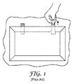
図1の従来技術に図示されるように、延伸剥離接着テープの従来の用途には、可視的なプルタブの存在が含まれることがある。しばしば、延伸剥離接着テープの特定部分の接着面は、接着テープのこの部分がプルタブとしての役割を果たすように、(例えば、コーティングの塗布、フィルムの積層等によって)非接着性とされる。 As illustrated in the prior art of FIG. 1, conventional applications of stretch release adhesive tapes may include the presence of visible pull tabs. Often, the adhesive surface of a particular portion of the stretch release adhesive tape is made non-adhesive (eg, by applying a coating, laminating a film, etc.) so that this portion of the adhesive tape serves as a pull tab.
PCT国際公開第WO 98/06652号には、従来の長い片面接着テープの末端部にプルタブ又は「把持部」を形成するのに使用できる長さ切断固定部が開示されている。長さ切断固定部は、把持部を包含する長いテープを、あらゆる所望の長さに切断する役割も果たす。把持部は、テープの末端部をそれ自体の上に折り返すことによって形成される。 PCT International Publication No. WO 98/06652 discloses a length cutting fixture that can be used to form a pull tab or “grip” at the end of a conventional long single-sided adhesive tape. The length cutting fixing part also serves to cut the long tape including the gripping part into any desired length. The grip is formed by folding the end of the tape over itself.
米国特許第5,491,012号(ルーマン(Luhmann))ら)には、再剥離可能な接着剤結合用接着フィルムのストリップが開示されており、ストリップの一端の両側には紫外線不透過性のカバーが提供され、それが同時に引っ張るためのタブとしての役割を果たす。 US Pat. No. 5,491,012 (Luhmann et al.) Discloses a strip of adhesive film for releasable adhesive bonding, which is UV opaque on both sides of one end of the strip. A cover is provided, which serves as a tab for pulling simultaneously.
米国特許第6,641,910号(ブリーズ(Bries)及びヨハンソン(Johansson))には、手動で係合可能なプルタブを形成するのに使用できる分割型ライナーを包含する延伸剥離テープが開示されている。 US Pat. No. 6,641,910 (Bries and Johansson) discloses a stretch release tape that includes a split liner that can be used to form a manually engageable pull tab. Yes.
出願人は、物体をともに固着するためのキット及び方法を開示する。多くの場合、細長い延伸剥離接着テープは、このような用途に使用される。このような延伸剥離テープは、典型的には、ユーザーが握って引っ張ってテープの延伸剥離特性を活性化し、その結果テープを取り外して物体を分離することのできる非接着性部分(プルタブと呼ばれることが多い)を含む。出願人は、本明細書において、目立たないか又は部分的に若しくは完全に隠れ得るプルタブによって満足のいく外観を提供できるキット及び方法を開示する。 Applicants disclose kits and methods for securing objects together. In many cases, elongated stretch release adhesive tapes are used for such applications. Such stretch release tapes are typically referred to as non-adhesive parts (pull tabs) where the user can grasp and pull to activate the stretch release properties of the tape so that the tape can be removed and the object separated. Many). Applicants disclose herein kits and methods that can provide a satisfactory appearance with a pull tab that can be inconspicuous or partially or completely hidden.
出願人は、選択箇所に手動で係合可能なプルタブを形成するために単一のタブフィルムを接着することのできる、延伸剥離接着テープの細長いストリップも開示する。この延伸剥離接着テープは、別個のストリップとして、又は別個のストリップに細分化できるシートとして、又はロール形態でユーザーに供給することができる。ロールが供給される場合、ユーザーは、ロールからあらゆる所望の長さの別個のストリップを切断し、タブフィルムを使用して、ストリップ上の所望の箇所に(例えば、接着剤ストリップの終端部に)プルタブを形成することができる。 Applicants also disclose an elongated strip of stretch release adhesive tape that can be bonded to a single tab film to form a pullable tab that can be manually engaged at selected locations. The stretch release adhesive tape can be supplied to the user as a separate strip, as a sheet that can be subdivided into separate strips, or in roll form. When a roll is supplied, the user cuts a separate strip of any desired length from the roll and uses a tab film to the desired location on the strip (eg, at the end of the adhesive strip). Pull tabs can be formed.
タブフィルムは複数の個別の片として供給されてもよく、この片は接着テープとともにパッケージ化されてもよいが、テープの接着面と接触しない。接着テープがロールとして供給される場合、タブ片は、ディスペンサー内にパッケージ化されてもよく、このディスペンサーは、接着テープロールが周りに巻きつけられたコアの上に配置されるか又はコアの内部に設置されてもよい。あるいは、ディスペンサー自体がコアを含んでもよく、即ち、例えば成形プラスチック片が利用されてもよく、この成形プラスチック片は、タブフィルム片用のホルダー/ディスペンサーとして、かつ、接着テープが巻きつけられるコアとしての両方の機能を果たす。 The tab film may be supplied as a plurality of individual pieces, which may be packaged with the adhesive tape, but do not contact the adhesive surface of the tape. If the adhesive tape is supplied as a roll, the tab pieces may be packaged in a dispenser, which is placed on or around the core around which the adhesive tape roll is wrapped. May be installed. Alternatively, the dispenser itself may include a core, i.e. a molded plastic piece may be used, for example, as a holder / dispenser for the tab film piece and as a core around which the adhesive tape is wrapped. Fulfills both functions.
タブフィルム片は、延伸剥離テープの接着面に強力に固着することのできる接着可能面を備えたフィルムから成ってもよい。このような構造は、プルタブを形成するために剥離ライナーの使用を伴う構造よりも優れた固着力を提供することができる。 The tab film piece may be made of a film having an adhesive surface that can be firmly fixed to the adhesive surface of the stretch release tape. Such a structure can provide better adhesion than a structure that involves the use of a release liner to form the pull tab.
一実施形態では、タブを形成するために、タブフィルムの1つの主表面の領域が、第1タブ/テープ固着領域を形成するために接着テープの細長い片の1つの主接着面に取付けられ、かつ、タブフィルム片の同一の主表面の別の領域が、第2タブ/テープ固着領域を形成するためにテープの他方の主接着面に取付けられる。一実施形態では、形成されたタブは、接着テープの細長い片の端縁部を越えて突出してもよい。更なる実施形態では、タブは、突起状タブ部の少なくとも一部がタブ/テープ固着領域の少なくとも一部分と重なり合った関係になる、折畳み位置に移動可能である。このような形体では、タブは、固着される物体の裏側に部分的に又は全体的に隠れてもよい。別の実施形態では、タブは、折畳み位置に移動可能であり、それによって突起状タブ部の一部が第1タブ/テープ固着領域の少なくとも一部分と重なり合った関係になるとともに、突起状タブ部の別の部分が第2タブ/テープ固着領域の少なくとも一部分と重なり合った関係になる。別の実施形態では、タブは、伸展位置に移動可能である。更なる実施形態では、タブは、折畳み状態と伸展状態との間で移動可能であってもよい。このような伸展式及び折畳み式のタブは、本明細書で定義されるような伸展比を呈してもよい。 In one embodiment, to form a tab, a region of one major surface of the tab film is attached to one major adhesive surface of an elongated piece of adhesive tape to form a first tab / tape fastening region; And another region of the same major surface of the tab film piece is attached to the other major adhesive surface of the tape to form a second tab / tape fastening region. In one embodiment, the formed tab may protrude beyond the edge of the strip of adhesive tape. In a further embodiment, the tab is movable to a folded position where at least a portion of the protruding tab portion is in an overlapping relationship with at least a portion of the tab / tape anchoring area. In such a configuration, the tab may be partially or totally hidden behind the object to be secured. In another embodiment, the tab is moveable to a folded position so that a portion of the protruding tab portion is in an overlapping relationship with at least a portion of the first tab / tape securing region and the protruding tab portion is Another portion is in an overlapping relationship with at least a portion of the second tab / tape fastening area. In another embodiment, the tab is movable to the extended position. In further embodiments, the tab may be movable between a folded state and an extended state. Such stretchable and foldable tabs may exhibit a stretch ratio as defined herein.
それ故、出願人は、一態様では、延伸剥離接着テープの長さの末端部に非接着性突起状プルタブを形成する方法であって、両方の表面が接着剤を含む、反対方向に面する第1及び第2主表面を有する細長い延伸剥離接着テープを提供することと、少なくとも一方の主表面が接着可能である、反対方向に面する第1及び第2主表面を有する単一片のタブフィルムを提供することと、タブ/テープ固着領域を形成するために、タブフィルムの接着可能な主表面の第1の領域を接着テープの第1主表面の接着剤含有領域と接触させることであって、前記領域が接着テープの終端部にあることと、タブフィルムの一部が細長い延伸剥離接着テープの終端部の端縁部を通り越えて突出するように、タブフィルムを接着テープの終端部の周りに巻きつけることと、タブ/テープ固着領域を形成するために、タブフィルムの接着可能な主表面を接着テープの第2主表面の接着剤含有領域と接触させることであって、前記領域が、接着テープの終端部にあることと、を含み、突起状タブ部を含む非接着性のプルタブが、細長い接着テープの終端部に形成されている方法を開示する。 Therefore, Applicants, in one aspect, are methods of forming non-adhesive protruding pull tabs at the length ends of stretch release adhesive tape, both surfaces containing adhesive and facing in opposite directions Providing an elongated stretch release adhesive tape having first and second major surfaces, and a single piece tab film having first and second major surfaces facing in opposite directions to which at least one major surface can be bonded And contacting the first area of the adhesive main surface of the tab film with the adhesive-containing area of the first main surface of the adhesive tape to form a tab / tape fastening area. The tab film is attached to the end of the adhesive tape such that the region is at the end of the adhesive tape and that a portion of the tab film protrudes beyond the end edge of the end of the elongated stretch release adhesive tape. Wrap around And contacting the adhesive main surface of the tab film with the adhesive-containing region of the second main surface of the adhesive tape to form a tab / tape fastening region, said region comprising an adhesive tape A method is disclosed in which a non-adhesive pull tab including a protruding tab portion is formed at an end portion of an elongated adhesive tape.
他の様々な態様では、出願人は、テープの感圧性接着剤を用いてプルタブを延伸剥離接着テープに取付け得るキット及び方法を開示する。接着テープの延伸剥離特性は、接着テープ自体のいずれの部分も握らずに、プルタブの突起状部分を握って引っ張ることによって活性化されてもよい。即ち、テープの接着面と固着された物体(1つ又は複数)の表面との間の固着を破断するために、タブを引っ張ることによって延伸剥離を活性化する一方で、テープの接着面とプルタブフィルム表面との間の固着を維持してもよい。一実施形態では、接着テープは、プルタブを引っ張ることによって、固着された物体から完全に剥離できる。代替実施形態では、プルタブは、接着テープを固着された物体から部分的に剥離させるとともに、接着テープを部分的に延伸させるために引っ張られてもよく、それによって接着テープの一部が物体の間から十分に突出し、その後、ユーザーは、接着テープの剥離を完了するために、接着テープ自体を握って引っ張ることができる。 In various other aspects, Applicants disclose kits and methods that can attach a pull tab to a stretch release adhesive tape using a tape pressure sensitive adhesive. The stretch release properties of the adhesive tape may be activated by grasping and pulling the protruding portion of the pull tab without grasping any part of the adhesive tape itself. That is, the adhesive surface of the tape and the pull tab are activated while activating the stretch release by pulling the tab to break the bond between the adhesive surface of the tape and the surface of the object (s) to which it is secured. Adhesion with the film surface may be maintained. In one embodiment, the adhesive tape can be completely peeled from the secured object by pulling on the pull tab. In an alternative embodiment, the pull tab may be pulled to partially peel the adhesive tape from the secured object and partially stretch the adhesive tape so that a portion of the adhesive tape is between the objects. And then the user can grasp and pull the adhesive tape itself to complete the peeling of the adhesive tape.
本開示において「上部」、「底部」、「上方」、「下方」、「前側」及び「後側」、並びに「第1」及び「第2」などの用語が使用されることがあるが、これらの用語は、その相対的な意味においてのみ使用されることを理解されたい。例えば、タブフィルムが、延伸剥離物品の(2つの主要面のうちの)第1主表面に取付けられるものとして説明される場合、特に明記しない限り、このような第1表面は、2つの表面のうちのいずれかであり得る。また図面において、類似の参照番号は、全体を通じて類似の特徴を示すのに使用される。図面及び図面中の要素は、注記しない限り、一定の縮尺には従っていない。 Although terms such as “top”, “bottom”, “upper”, “lower”, “front” and “rear”, and “first” and “second” may be used in the present disclosure, It should be understood that these terms are used only in their relative meaning. For example, when a tab film is described as being attached to a first major surface (of two major surfaces) of a stretch-release article, such a first surface is defined as two surfaces unless otherwise specified. It can be any of them. Also in the drawings, like reference numerals are used throughout to designate like features. The drawings and elements in the drawings are not to scale unless otherwise noted.
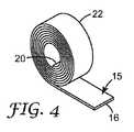
まず図2を参照すると、第1主表面12と、第2(反対側)主表面14と、端縁部16を含む終端部15とを含む、細長い延伸剥離接着テープを含む物品10が示されている。図3に例示された実施形態では、物品10は、第2末端部20を備えた不連続の長さ18として提供される。代替実施形態(図示せず)では、延伸剥離接着テープ材料は、個々の物品10が分離され得る連続シートの形態で提供される。更に別の実施形態では、延伸剥離接着テープ材料は、第2末端部20がロールの内側末端部にある(図4に図示されるような)ロール22の形態で提供される。したがって、この実施形態では、延伸剥離接着テープは、最終用途に応じて選択された長さの複数のストリップを切断することのできる、不定の長さを有する細長いストリップとして提供され得る。
Referring first to FIG. 2, an
延伸剥離接着テープ10は、第1主表面12及び第2主表面14上に接着剤を含む。接着剤は、基材にしっかりと接着され、その後にテープを延伸することによってそこから取り外され得る、あらゆる感圧性接着剤を含み得る。したがって、延伸剥離接着テープは、感圧性接着剤がその上に配置(例えばコーティング)された、弾性的な裏材、又は非常に伸張性の高い実質的に非弾性的な裏材を含み得る。あるいは、テープは、中実の(solid)、弾性的な感圧性接着剤から形成され得る。したがって、この文脈において、用語「テープ」は、(残留接着剤の別個の層を備えた裏材を含む製品に加えて)接着剤の単一の、一体の、又は中実の(solid)構造を含む製品を包含する。好適な延伸剥離テープは、米国特許第4,024,312号(コルプマン(Korpman))、独国特許第33 31 016号、米国特許第5,516,581号(クレッケル(Kreckel)ら)、及びPCT国際公開第WO 95/06691号(ブリーズ(Bries))ら)に記載されている。
The stretch release
一方又は両方の接着面12及び14には、存在するならば、ライナー、即ち剥離ライナーが供給され得る。1つ又は複数のライナー(図2〜4では図示せず)は、あらゆる従来の容易に取り外し可能なライナーであり得る。典型的なライナーとしては、例えば、紙、又はポリエチレン、ポリプロピレン、若しくはポリエステルのような高分子フィルムから形成された裏材が挙げられ、これは、シリコーン、フッ素性化学物質、又は表面を実質的に非接着性とする、その他のいずれかの従来より既知のコーティング(例えば、低接着性バックサイズとして当該技術分野において既知のコーティング)のような剥離剤によってコーティングされる。多くの場合に好ましいライナーは、シリコーンコーティングされた紙である。多くの場合、両方の主表面上に剥離剤が存在しているライナーが延伸剥離接着テープとともに使用され、延伸剥離接着テープの長さがロールを含む場合、ライナーの一方の表面が接着面12と接触し、ライナーの他方の表面が接着面14と接触する。そのような場合、剥離ライナーを1つだけ使用する必要がある。存在するならば、このようなライナーは、典型的には延伸剥離接着テープを使用するときに取り外される。
One or both
(図5〜8に図示されるような)タブフィルム30もまた本明細書に開示される。タブフィルム30は、少なくとも1つの接着可能面を備えるとともに、使用可能なタブを形成するのに十分な強度である、あらゆるフィルム材を含み得る。接着可能面とは一般に、タブフィルムが、感圧性接着剤から取り外し可能ではなく、あるいは、タブフィルムの接着可能面、タブフィルム材料、延伸剥離テープの感圧性接着剤、又は延伸剥離テープの弾性裏材(存在するならば)を損傷せずに取り外しができないように、(例えば米国特許第5,516,581号(クレッケル(Kreckel)ら)に更に詳細に記載され、延伸剥離接着テープに通常使用されるような)感圧性接着剤に固着することのできる表面を指す。そのようなものとして、接着可能面は、上記のような剥離ライナーを含まないあらゆる表面を含んでもよい。即ち、接着可能面とは、剥離コーティング、低接着性バックサイズ、処理又は成分、例えばシリコーン又はシリコーン含有材料、フッ素化又はフッ素含有材料、フルオロシリコーン材料などを含まない表面を指す。タブフィルムに好適な材料の代表例としては、ポリオレフィン、例えば、高密度ポリエチレン、低密度ポリエチレン、線状低密度ポリエチレン、及び線状超低密度ポリエチレンを包含するポリエチレン、ポリプロピレン、並びにポリブチレン、ビニル共重合体、例えば、可塑化された及び可塑化されていないポリ塩化ビニル、並びにポリビニルアセテート、オレフィン共重合体、例えばエチレン/メタクリレート共重合体、エチレン/酢酸ビニル共重合体、アクリロニトリル−ブタジエン−スチレン共重合体、及びエチレン/プロピレン共重合体、アクリル重合体及び共重合体、並びに前述の組み合わせが挙げられる。ポリエステルベースの材料(例えばポリ(エチレンテレフタレート)、ポリ(ブチレンテレフタレート)等)も使用されてもよい。あらゆるプラスチック又はプラスチック及びエラストマー材の混合物又はブレンド、例えばポリプロピレン/ポリエチレン、ポリウレタン/ポリオレフィン、ポリウレタン/ポリカーボネート、ポリウレタン/ポリエステルを使用することもできる。セルロースフィルム(例えば紙、セロハン等)を使用することもできる。タブフィルムはまた、例えば、充填フィルム、例えば炭酸カルシウム充填ポリオレフィンのような充填材料から調製することができる。タブフィルムは、例えば押出成形、共押出し成形、溶液流延などのようなあらゆる既知のフィルム形成方法によって作製され得る。多くの用途に関して、透明フィルムが好ましいことがある。
A tab film 30 (as illustrated in FIGS. 5-8) is also disclosed herein.
タブフィルム材料は、それから形成されたタブ(後に説明する)が握って引っ張られるときに破断又は裂断しないよう、十分な厚さ及び強度を有すべきである。即ち、タブフィルム30は、延伸剥離接着テープの延伸剥離特性を活性化するのに使用される力に耐えるべきである。様々な実施形態において、タブフィルムは、厚さが少なくとも約12マイクロメートルであり得る。しかしながら、タブフィルムは、取り扱いが困難になるほど厚さであってはならない。様々な実施形態において、タブフィルムは、最大限で厚さが約75マイクロメートル又は150マイクロメートルである。
The tab film material should have sufficient thickness and strength so that the tabs formed therefrom (discussed below) do not break or tear when gripped and pulled. That is, the
タブフィルム材料の接着可能面は、延伸剥離接着テープの接着面に対するその接着能力を向上させるように処理されてもよい。例えば、コロナ放電、プラズマ放電、火炎処理、電子ビーム照射、紫外線、化学蒸着、酸エッチング、又は化学的下塗りが使用されてもよい。一実施形態では、接着性を向上させるために、感圧性接着剤がタブフィルムの接着可能面上に配置される。 The bondable surface of the tab film material may be treated to improve its adhesion ability to the adhesive surface of the stretch release adhesive tape. For example, corona discharge, plasma discharge, flame treatment, electron beam irradiation, ultraviolet light, chemical vapor deposition, acid etching, or chemical primer may be used. In one embodiment, a pressure sensitive adhesive is placed on the adhesive side of the tab film to improve adhesion.
タブフィルムの他の表面は、本明細書で規定されるように接着可能である必要がないことがある。しかしながら、この他の表面は、ユーザーによって容易に把持可能であるべきであり、また、把持し易さを向上させるために処理(粗面等)を含んでもよい。本明細書で後に詳細に記載されるように、他の処理が所望に応じて使用されてもよい。 The other surface of the tab film may not need to be adhesive as defined herein. However, this other surface should be easily gripped by the user and may include a treatment (rough surface, etc.) to improve ease of gripping. Other processes may be used as desired, as described in detail later herein.
様々な実施形態において、接着可能面及び把持可能面の一方又は両方は、特定の領域内で、例えばストライプ塗り、模様塗りなどによって、その表面の異なる領域内で異なる特性を提供するように処理されてもよい。例えば、(下塗りによって、又は接着剤コーティング等によって達成される)より高い接着特性の領域が提供されてもよい。その代わりに、又はそれに加えて、(剥離剤コーティング等によって達成される)より低い接着特性の領域が提供されてもよい。 In various embodiments, one or both of the bondable surface and the grippable surface are treated to provide different properties within a particular area, such as by stripe coating, pattern coating, etc., in different areas of the surface. May be. For example, regions of higher adhesive properties (achieved by priming or by adhesive coating or the like) may be provided. Alternatively or in addition, regions of lower adhesive properties (achieved by a release agent coating or the like) may be provided.
様々な実施形態において、タブフィルム30は、延伸剥離接着テープとともにキットで提供されてもよい。タブフィルムは、別個の片として、又は別個の片が切り離され得るロール形態で存在していてもよい。別個の片として提供されるとき、ディスペンサー、例えば、図5に図示される代表的なポップアップ式ディスペンサー80内にタブフィルム片30をパッケージ化することができ、1回に1片のタブフィルム30を取り外して使用することができる。延伸剥離接着テープのロール22と組み合わせて使用されるとき、タブディスペンサー80は、図6に図示されるように、延伸剥離接着テープのロール22に装着され得る。
In various embodiments, the
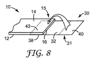
ここで図7を参照すると、一実施形態では、細長い延伸剥離テープ10が提供される。接着テープの第1主表面12の少なくとも終端部15において、接着剤領域36が提供される。(ライナーが存在するならば、少なくとも接着剤領域36を露出させるようにライナーを取り除く)。タブフィルム片30が提供される。タブフィルム30の接着可能面32の第1の領域34は、タブ/テープ固着領域38(図8に図示)を形成するように、領域36と接触し、領域36に接着する。次いで、タブフィルム30は、接着テープの終端部15の周りに巻きつけられる。図8における代表的な方式に図示されるように、一実施形態では、タブフィルムは、細長い延伸剥離接着テープに対して平行な方向に巻きつけられる(例えば、テープの終端部15の端縁部16の周りに巻きつけられる)。図9における代表的な方式で図示されるように、代替実施形態では、タブフィルムは、細長い長さの延伸剥離接着テープに対して垂直な方向に巻きつけられる(例えば、テープの側縁部の周りに巻きつけられる)。接着テープの第2主表面14の少なくとも終端部において、接着剤領域42が提供される(同様に、存在するならば、この領域を露出させるようにライナーを取り除く)。タブフィルムの接着可能面32の第2の領域40は、タブ/テープ固着領域39(図10に図示)を形成するように、接着剤領域42と接触され、接着剤領域42に接着される。様々な実施形態において、それぞれの固着領域38及び39は、接着テープの端縁部16から細長いテープに沿って少なくとも約4、8又は12mmの距離にわたって存在している。
Referring now to FIG. 7, in one embodiment, an elongated
図10に関して、この方法は、細長い接着テープ10の終端部15において、タブ50を提供する。タブ50は、タブ/テープ固着領域38及び39を介して延伸剥離接着テープに取付けられる。図10に例示された実施形態では、タブは、テープの終端部15の端縁部16を越えて突出している。しかしながら、代替実施形態では、タブは、端縁部16を通り越えて突出しないように位置してもよい。様々な実施形態において、タブは、折畳み位置に、及び/又は伸展位置に移動可能であり、以下に詳細に記載するように2つの位置の間で交換可能であってもよい。
With reference to FIG. 10, the method provides a
細長い延伸剥離接着テープ10は、2つの物体をともに固着するのに使用できる。図11に示した一実施形態では、タブフィルムは、物体60及び62がともに固着された後の伸展位置を含む。したがって、例えば、タブ50の部分54は、物体62の縁部を越えて突出して可視されてもよい。一実施形態では、タブは、見えにくいように透明な材料で作製される。別の実施形態では、キットは、(例えば、延伸剥離接着テープのロールが付属したディスペンサー内にパッケージ化された)異なる色彩の複数のタブフィルム片を備えてもよい。したがって、この実施形態では、異なる色彩の様々なタブフィルムから、固着されるべき物体の隣接面(例えば、物体60の表面63)の色彩に最も密接に適合する色彩のタブフィルムが選択されてもよい。
The elongated stretch release
図12に示した別の実施形態では、タブ50は、突起状タブ部54の少なくとも一部がタブ/テープ固着領域38(又は39)の少なくとも一部分と重なり合った関係になるように、折畳み位置に移動可能である。これにより、突起状部分54の少なくとも一部を、物体62の裏側に部分的に又は全体的に隠すことが可能になる。一実施形態では、タブ/テープ固着領域38は、タブフィルムの突起状部分をテープの接着面14と接触させずに折畳むことができるように、寸法設定され、位置決めされる。代替実施形態では、タブ/テープ固着領域38は、後に詳細に説明するように、タブの突起状部分の少なくとも一部を接着面14の少なくとも一部分と接触させるように折畳むことができるように、寸法設定され、位置決めされる。
In another embodiment shown in FIG. 12, the
突起状タブ部54は、延伸剥離接着テープを使用して物体60及び62をともに固着する前に、折畳み位置に配置され得る。あるいは、物体をともに固着することができ、その後に突起状部分54を固着領域39(又は38)と物体60(又は62)との間の空間に折畳むことができる。
The protruding
この実施形態では、タブの折畳まれた部分は、延伸剥離接着テープを活性化すること及び物体60及び62を剥離することが所望されるまで、部分的に又は全体的に隠れたままである。その時、タブは展開され(所望する場合、ワイヤ、折畳まれていない紙用クリップ、つまようじ等のような小型用具をこの操作に使用することができる)、伸展位置に移動され得て、それによってユーザーは、接着テープの延伸剥離特性を活性化するために、タブを握って引っ張ることができる。一実施形態では、タブが伸展位置にあるとき、ユーザーは、延伸剥離接着テープ自体のいずれの部分も握って引っ張らずにテープの延伸剥離特性を活性化するために、タブの突起状部分を握って引っ張ることができる。
In this embodiment, the folded portion of the tab remains partially or totally hidden until it is desired to activate the stretch release adhesive tape and release the
伸展位置は、タブの突起状部分が主に平面形体を含むように配置されている位置を概ね示し、ここで、タブフィルム部分33及び35は、(図13a及び13bにおける代表的な方式に図示されるように)極めて近接しているか又は接触している。そのように伸展されるとき、テープ端縁部16から最も遠い点(本明細書で説明する他の測定距離のように、細長いテープに対して平行な方向に測定される)は、点52を含み、この点52は、様々な実施形態において、接着テープの端縁部16を越えて少なくとも約10又は15mmであってもよい。様々な実施形態において、点52は、端縁部16を越えて最大限で約30又は40mmであってもよい。タブフィルムが細長い長さに対して平行な方向にテープの終端部の周りに巻きつけられた一実施形態では、最遠隔点52は、タブフィルムの連続的な部分である(また、後に詳細に説明するように、図13bに示すような折り目53を含んでもよい)。(図9に示すような)タブフィルムが細長い延伸剥離接着テープに対して垂直な方向に終端部の周りに巻きつけられた代替実施形態では、最遠隔点は、タブフィルムの縁部33により形成されてもよい。
The extended position generally indicates the position at which the protruding portion of the tab is disposed to include a predominantly planar feature, where the
一実施形態では、タブは、端縁部16から最遠隔点52まで完全に伸展した距離(即ち、図13aにおける距離β)が、テープ端縁部16からタブ/テープ固着領域38の縁部37までの距離よりも小さく(及び/又はテープ端縁部16からタブ/テープ固着領域39の縁部36までの距離よりも小さく)なるように、寸法設定され、位置決めされ得る。この実施形態では、(図14に例示されたように)タブが折畳まれているとき、タブフィルムの把持可能面31は、接着面12又は14と接触しないことになる。
In one embodiment, the tab has a fully extended distance from the
代替実施形態では、タブは、端縁部16から最遠隔点52までの完全に伸展した距離(即ち、図13aにおける距離β)が、テープ端縁部16からタブ/テープ固着領域38の縁部37までの距離を超える(及び/又はテープ端縁部16からタブ/テープ固着領域39の縁部36までの距離を超える)ように、寸法設定され、位置決めされ得る。この実施形態では、タブが折畳まれているとき、タブの表面31は、接着面12又は14の少なくとも一部分と接触して配置されてもよい。そのような構成は、タブが展開されることが所望されるときまで、折畳まれた所定の位置で接着剤によってタブを保持しているのが、希望される状況に有利であってもよい。したがって、タブは、折畳まれたときにタブの突起状部分の領域が接着面12又は14の領域と接触し得るように、寸法設定され、位置決めされてもよく、この接着面12又は14の領域は、タブを折畳み位置に保持するのに十分に大きいが、タブをうまく接着面12又は14から引き離して展開するのに十分に小さい。様々な実施形態において、タブは、このようなタブ/接着剤の重なり合った領域が、タブ/テープ固着領域の縁部37又は縁部36から細長いテープに沿って少なくとも約2、4又は6mmの距離にわたって存在するように寸法設定され、位置決めされてもよい。代替実施形態では、タブは、このようなタブ/接着剤の重なり合った領域が、タブ/テープ固着領域の縁部37又は縁部36から細長いテープに沿って最大限で約14、12又は10mmの距離にわたって存在するように寸法設定され、位置決めされてもよい。様々な追加の実施形態では、折畳まれたタブが接着面に付着できるが、後に剥離できるように所望の特性のバランスを達成するために、タブフィルムの表面31の少なくとも一部分が、(例えば、接着性を増強するための下塗り処理、又は接着性を低減するための低エネルギー処理の使用により)処理されてもよい。このような処理は、タブフィルムの表面31の全体に適用されてもよく、あるいは、指定の領域に適用されてもよい。
In an alternative embodiment, the tab has a fully extended distance from the
代替実施形態では、タブ表面31の少なくとも一部分が、接着剤(例えば感圧性接着剤)を含んでもよい。一実施形態では、タブ50の突起状部内の表面31の一部が、タブ/テープ固着領域38又は39内の表面31の一部に固着可能であるように接着剤を含み得る。あるいは、タブ/テープ固着領域38又は39内の表面31の一部が、タブ50の突起状部分内の表面31の一部に固着可能であるように接着剤を含み得る。接着剤の量は、(例えば、模様塗り又はストライプ塗りによって)選択することができ、及び/又は、接着剤組成物は、タブを展開することが所望されるときまでタブを折畳み位置に保持できるように、所望の固着力を有するように選択することができる。
In an alternative embodiment, at least a portion of the
折畳み位置は、(図14における代表的な方式に図示されるように)突起状タブ部の少なくとも一部がタブ/テープ固着領域38又は39の少なくとも一部分と重なり合った関係になるように、タブの突起状部分が位置決めされている位置を概ね示す。そのように折畳まれたとき、テープ端縁部から最も遠い点は、点55を含む。
The folded position is such that at least a portion of the protruding tab portion (as illustrated in the representative manner in FIG. 14) is in an overlapping relationship with at least a portion of the tab /
図13a及び14に例示されるように、伸展比は、折畳まれたときのタブの突出距離(図14におけるテープ端縁部16から最遠隔点55までの距離α)に対する、伸展されたときのタブの突出距離(図13aにおけるテープ端縁部16から最遠隔点52までの距離β)の比として定義され得る。様々な実施形態において、このβ/α伸展比は、少なくとも約3、5、又は7であり得る。
As illustrated in FIGS. 13a and 14, the stretch ratio is when extended relative to the protruding distance of the tab when folded (distance α from the
様々な実施形態において、タブフィルム片は、タブの折畳み位置への移動及び/又はその位置での維持の容易化のために、タブの伸展位置への移動及び/又はその位置での維持の容易化のために、あるいはその両方のために、1つ又は複数の折り目を含む。タブに線形領域に沿って優先的に折れ曲がる傾向を有するタブフィルムを提供するために、このような折り目は、タブフィルム材料が処理(例えば脆弱化、穿孔、アブレーション等)された線形領域を含んでもよい。あるいは、線形領域に沿って特定の方向に優先的に折れ曲がる傾向を有するタブフィルムを提供するために、このような折り目は、フィルム材が偏倚(折畳み、しわ形成等)された線形領域を含んでもよい。一実施形態では、このような折り目は、細長い延伸剥離物品に対して横方向に配向されるように、タブフィルムの短軸に対して平行に配向される(図13bにおける折り目53によって例示される)。
In various embodiments, the tab film piece can be easily moved to and / or maintained in the extended position of the tab to facilitate movement and / or maintenance of the tab in the folded position. One or more folds are included for either or both. In order to provide a tab film that has a tendency to bend preferentially along the linear region on the tab, such folds may include linear regions where the tab film material has been treated (eg, weakened, perforated, ablated, etc.). Good. Alternatively, in order to provide a tab film that has a tendency to preferentially bend along a linear region in a particular direction, such folds may include linear regions in which the film material is biased (folded, wrinkled, etc.). Good. In one embodiment, such folds are oriented parallel to the minor axis of the tab film so that they are oriented transversely to the elongated stretch release article (illustrated by
一実施形態では、先の説明のように、タブフィルムは、タブが伸展位置に配置されたときに最遠隔点52において折り目線53が自然に形成されるように、折り目を含んでもよい(図13bに例示される)。別の実施形態では、タブをZ形折畳み位置に配置できるよう、複数の折り目がタブフィルムに提供される。代表的なZ折畳み式タブフィルムは、図15に示されており、ユーザーがタブフィルムの少なくとも1つの66の一部をタブ−テープ固着領域38と重なり合った関係に配置するのを可能にする働きをする、(少なくとも)2つの横の折り目64及び65を有する。一実施形態では、折り目64及び65は、反対方向に偏倚している。
In one embodiment, as described above, the tab film may include a fold so that a
別の実施形態では、タブフィルムは、適切に寸法設定され、位置決めされ、折り目は、タブ/テープ固着領域38が一部66よりも物品10の細長い方向においてより大きな範囲であるように位置決めされ、離間される。この実施形態では、(図15に例示されるように)タブがZ形に折畳まれるとき、タブは、接着面12と接触する可能性が低い。同様に、一実施形態では、折り目64は、接着面12が露出しないように、端縁部16と同一平面に位置決めされる。代替実施形態では、タブフィルムは、適切に寸法設定され、位置決めされ、折り目は、タブ/テープ固着領域38が部分66よりも物品10の細長い方向においてより小さい範囲であるように位置決めされ、離間され、それによってタブ部66が接着面12の少なくとも一部分と接触して配置されてもよい。上述のように、このような形体は、タブを展開することが所望されるときまで、タブを接着剤手段により折畳み位置に保持することが所望される状況において有利なことがある。
In another embodiment, the tab film is appropriately sized and positioned, and the fold is positioned so that the tab /
更なる実施形態が図16に示される。この2重Z形折畳み構成では、少なくとも4つの折り目、即ち、図15に関して述べた折り目64及び65、並びに2つの同様の折り目74及び75が提供され、それによってタブは、延伸剥離物品の反対側にZ形に折畳まれ、同様の効果を得ることができる。様々な実施形態において、折り目74及び75は反対方向に偏倚しており、またこれらは折り目64及び65に関して上述したのと同様の方式で離間して位置決めされ、同様の効果を得てもよい。二重Z形折畳み形体を提供する折り目に加えて、追加の折り目53が、任意に、先の説明のように最大伸展位置に配置され得る。
A further embodiment is shown in FIG. In this double Z-fold configuration, at least four folds are provided, ie, folds 64 and 65 described with respect to FIG. 15, and two
図16に示すように、タブ50は、タブが距離αをおいて突出するように、二重Z形折畳み位置に配置され得る。(これは、延伸剥離接着テープが物体60及び62の一方又は両方に固着された後に行われてもよいが、好ましくは、タブは、延伸剥離接着テープが物体のいずれかに固着される前に折畳まれる。)延伸剥離を活性化することが所望されるとき、タブは、図17に示すように、タブが距離βをおいて突出するように、伸展位置に(先に説明されるように)展開され移動され得る。このような二重Z形折畳み設計によって、タブは、本明細書で先に規定されたように、高い伸展比を備えることが可能になる。様々な実施形態において、この伸展比は、少なくとも約3、5、又は7であり得る。
As shown in FIG. 16, the
このような本明細書に記載のような折り目は、タブを折畳み形体に迅速かつ容易に配置するための、及び迅速かつ容易にタブをそこから伸展位置に変えるための、既成の能力をユーザーに提供する。様々な実施形態において、タブフィルムには、少なくとも1つの、2つの、3つの、4つの、又は5つの折り目が供給され得る。様々な実施形態において、延伸剥離接着テープを含むキットは、折畳まれた、Z形に折畳まれた、又は二重Z形に折畳まれた形体に予め構成されたタブフィルム片とともに供給され得る。タブフィルム片は、これらの形体のいずれかでディスペンサー内にパッケージ化されてもよい。あるいは、タブフィルム片は、折畳まれない(例えば平坦である)が、ユーザーがタブフィルム片を容易に折畳むことができるように折り目を備えて供給され得る。 Such folds as described herein provide the user with a ready-made ability to quickly and easily place the tab in the folded configuration and to quickly and easily change the tab from there to the extended position. provide. In various embodiments, the tab film can be provided with at least one, two, three, four, or five folds. In various embodiments, a kit comprising a stretch release adhesive tape is supplied with a tab film piece pre-configured in a folded, Z-folded, or double-Z-folded configuration. obtain. The tab film piece may be packaged in a dispenser in any of these forms. Alternatively, the tab film piece is not folded (eg, flat), but can be supplied with a fold so that the user can easily fold the tab film piece.
一実施形態では、細長い延伸剥離接着テープは、一方又は両方の終端部にタブを取付けることのできる別個のストリップとして提供される。それ故、1つ又は複数のタブの形成後に、延伸剥離接着テープ物品は、2つの物体をともに固着するための使用準備が整えられる。タブが取付けられたときに細長い長さがロールの一部である代替実施形態では、細長い長さは、ロールから引き離されて使用される(その後、所望する場合は第2タブが他の末端部に取付けられ得る)。最大の適応性のために、ロールは、ユーザーがいずれかの所望の長さの細長い片を切断できるように提供されてもよい。あるいは、引裂きによって細長い長さを切り離すことができるように、断続的な脆弱線(即ち、刻み目、穿孔等)が、延伸剥離接着テープの幅にわたって横断方向に提供され得る。 In one embodiment, the elongated stretch release adhesive tape is provided as a separate strip that can have a tab attached to one or both ends. Thus, after formation of one or more tabs, the stretch release adhesive tape article is ready for use to secure the two objects together. In an alternative embodiment where the elongate length is part of the roll when the tab is attached, the elongate length is used pulled away from the roll (the second tab is then used at the other end if desired). Can be mounted on). For maximum flexibility, rolls may be provided to allow the user to cut any desired length of strip. Alternatively, intermittent lines of weakness (ie, nicks, perforations, etc.) can be provided across the width of the stretch release adhesive tape so that the elongated length can be cut off by tearing.
本発明の多数の実施形態を記載してきた。いずれにしても、本発明から逸脱することなく様々な修正を行ってもよいことが理解されるであろう。したがって、その他の実施形態も、以下の特許請求の範囲の範疇にある。 A number of embodiments of the invention have been described. In any event, it will be understood that various modifications may be made without departing from the invention. Accordingly, other embodiments are within the scope of the following claims.
Claims (4)
両方の表面が接着剤を含む、第1及び第2主表面(12,14)を有する細長い延伸剥離接着テープ(10)を提供する工程と、
少なくとも一方の主表面が接着可能である、第1及び第2主表面(32,31)を有する単一片のタブフィルム(30)を提供する工程と、
第1タブ/テープ固着領域(38)を形成するために、前記タブフィルム(30)の前記接着可能な主表面(32)の第1の領域(34)を前記接着テープ(10)の前記第1主表面(12)の接着剤含有領域(36)と接触させる工程であって、前記接着テープ(10)の前記第1主表面(12)の前記接着剤含有領域(36)が、前記接着テープ(10)の終端部(15)にある工程と、
前記タブフィルム(30)の一部が前記細長い延伸剥離接着テープ(10)の前記終端部(15)の端縁部(16)を通り越えて突出するように、前記タブフィルム(30)を前記接着テープ(10)の前記終端部(15)の周りに巻きつける工程と、
第2タブ/テープ固着領域(39)を形成するために、前記タブフィルム(30)の前記接着可能な主表面(32)の第2の領域(40)を前記接着テープ(10)の前記第2主表面(14)の接着剤含有領域(42)と接触させる工程であって、前記接着テープ(10)の前記第2主表面(14)の前記接着剤含有領域(42)が、前記接着テープ(10)の前記終端部(15)にある工程と、を含み、
突起状タブ部(54)を含む非接着性のプルタブ(50)が、前記細長い接着テープ(10)の終端部(15)に形成される、方法。 The termination portion of the stretch releasing adhesive tape (10) (15), a method of forming a non-adhesive protruding pull tab (50),
A step of both surfaces of providing comprises an adhesive, an elongate length of stretch releasing adhesive tape having first and second major surfaces (12, 14) (10),
At least one main surface is bondable, providing a tab film (30) of a single piece having first and second major surfaces (32, 31),
In order to form a first tab / tape fastening region (38) , a first region (34) of the adherent major surface (32) of the tab film (30 ) is formed in the first region of the adhesive tape (10) . comprising contacting the adhesive-containing region (36) of the first major surface (12), wherein said adhesive-containing region of the first major surface of the adhesive tape (10) (12) (36), the adhesive A step at the end (15) of the tape (10) ;
So as to protrude beyond through edge (16) of the end portion of a part the elongated stretch releasing adhesive tape (10) of the tub film (30) (15), the said tab film (30) Winding around the end portion (15) of the adhesive tape (10) ;
In order to form a second tab / tape fastening region (39) , a second region (40) of the adherent main surface (32) of the tab film (30 ) is formed in the second region of the adhesive tape (10) . comprising contacting the adhesive-containing region (42) of the second major surface (14), wherein said adhesive-containing region of the second major surface of the adhesive tape (10) (14) (42), the adhesive And at the end (15) of the tape (10) ,
Non-adhesive pull tab comprising protruding tab portion (54) (50) is formed on the end portion (15) of said elongated adhesive tape (10), the method.
Applications Claiming Priority (3)
| Application Number | Priority Date | Filing Date | Title |
|---|---|---|---|
| US11/769,923 US7892384B2 (en) | 2007-06-28 | 2007-06-28 | Removable adhesive tape and pull tab, and method of forming |
| US11/769,923 | 2007-06-28 | ||
| PCT/US2008/065611 WO2009005929A1 (en) | 2007-06-28 | 2008-06-03 | Removable adhesive tape and pull tab, and method of forming |
Publications (3)
| Publication Number | Publication Date |
|---|---|
| JP2010531917A JP2010531917A (en) | 2010-09-30 |
| JP2010531917A5 JP2010531917A5 (en) | 2011-06-02 |
| JP5323068B2 true JP5323068B2 (en) | 2013-10-23 |
Family
ID=40158980
Family Applications (1)
| Application Number | Title | Priority Date | Filing Date |
|---|---|---|---|
| JP2010514924A Expired - Fee Related JP5323068B2 (en) | 2007-06-28 | 2008-06-03 | Removable adhesive tape and pull tab, and forming method |
Country Status (8)
| Country | Link |
|---|---|
| US (1) | US7892384B2 (en) |
| EP (1) | EP2164913B1 (en) |
| JP (1) | JP5323068B2 (en) |
| KR (1) | KR101505220B1 (en) |
| CN (1) | CN101688091B (en) |
| AU (1) | AU2008270911B2 (en) |
| CA (1) | CA2691822C (en) |
| WO (1) | WO2009005929A1 (en) |
Families Citing this family (9)
| Publication number | Priority date | Publication date | Assignee | Title |
|---|---|---|---|---|
| US7857130B2 (en) * | 2007-06-28 | 2010-12-28 | 3M Innovative Properties Company | Removable adhesive tape and pull tab film, and kits |
| US7824753B2 (en) * | 2007-06-28 | 2010-11-02 | 3M Innovative Properties Company | Removable adhesive tape with foldable pull tab |
| TWI466783B (en) * | 2011-12-29 | 2015-01-01 | Yu Ping Philip Lin | Film assembly and method for attaching the same |
| WO2015069268A1 (en) * | 2013-11-08 | 2015-05-14 | Otis Elevator Company | Guide rail for elevator |
| DE102016223783A1 (en) * | 2016-11-30 | 2018-05-30 | Tesa Se | Applicator for plasma-initiated adhesive tapes with folding mechanism |
| US10221883B2 (en) | 2017-04-07 | 2019-03-05 | Artskills, Inc. | Apparatus for supporting articles |
| US10870258B2 (en) | 2017-08-24 | 2020-12-22 | Guangdong Oppo Mobile Telecommunications Corp., Ltd. | Stretch releasing adhesive assembly, housing assembly and mobile terminal |
| JP7017151B2 (en) * | 2019-02-06 | 2022-02-08 | 株式会社村田製作所 | Pasting member |
| JP2022074877A (en) * | 2020-11-05 | 2022-05-18 | レノボ・シンガポール・プライベート・リミテッド | Mobile information instrument and double-sided adhesive tape |
Family Cites Families (28)
| Publication number | Priority date | Publication date | Assignee | Title |
|---|---|---|---|---|
| US3930502A (en) | 1974-11-20 | 1976-01-06 | Johnson & Johnson | Disposable diaper with a tape closure system having a double-folded tab |
| US4024312A (en) | 1976-06-23 | 1977-05-17 | Johnson & Johnson | Pressure-sensitive adhesive tape having extensible and elastic backing composed of a block copolymer |
| DE3331016A1 (en) | 1983-04-06 | 1984-10-11 | Beiersdorf Ag, 2000 Hamburg | Adhesive film for releasable adhesive bonds |
| TW215105B (en) * | 1990-12-20 | 1993-10-21 | Minnesota Mining & Mfg | |
| US5516581A (en) | 1990-12-20 | 1996-05-14 | Minnesota Mining And Manufacturing Company | Removable adhesive tape |
| US5103970A (en) | 1991-04-22 | 1992-04-14 | Fiskars Oy Ab | Collapsible display system |
| US5111381A (en) | 1991-08-12 | 1992-05-05 | Motorola, Inc. | H-bridge flyback recirculator |
| DE4222849C2 (en) | 1992-07-11 | 2000-02-10 | Beiersdorf Ag | Use a strip of adhesive film for releasable gluing |
| WO1995006691A1 (en) | 1993-08-31 | 1995-03-09 | Minnesota Mining And Manufacturing Company | Removable foam adhesive tape |
| DE4339604C2 (en) | 1993-11-20 | 1996-06-05 | Beiersdorf Ag | Use of a section of adhesive film for a detachable bond |
| US5824380A (en) | 1996-05-09 | 1998-10-20 | Menasha Corp. | Package reclosure label and package |
| DE59708107D1 (en) | 1996-07-06 | 2002-10-10 | Tesa Ag | Use a strip of adhesive film |
| DE19631964A1 (en) | 1996-08-08 | 1998-02-12 | Beiersdorf Ag | Cutting device |
| US5759342A (en) | 1996-10-09 | 1998-06-02 | Minnesota Mining And Manufacturing Company | Hand-held tape dispenser |
| DE29619424U1 (en) | 1996-11-08 | 1997-10-02 | Tmtape B V | Cover sheet for painting and painting work |
| US6972141B1 (en) | 1997-12-12 | 2005-12-06 | 3M Innovative Properties Company | Removable adhesive tape laminate and separable fastener |
| DE19849199A1 (en) | 1998-10-26 | 2000-04-27 | Beiersdorf Ag | Adhesive strips |
| US6541089B1 (en) * | 1999-08-24 | 2003-04-01 | 3M Innovative Properties Company | Stretch releasing adhesive tape with integral pull tab |
| US6641910B1 (en) * | 1999-08-24 | 2003-11-04 | 3M Innovative Properties Company | Stretch releasing adhesive tape with segmented release liner |
| SG94851A1 (en) * | 2000-07-12 | 2003-03-18 | Tokyo Electron Ltd | Substrate processing apparatus and substrate processing method |
| US6894204B2 (en) | 2001-05-02 | 2005-05-17 | 3M Innovative Properties Company | Tapered stretch removable adhesive articles and methods |
| US6641096B2 (en) | 2001-09-13 | 2003-11-04 | 3M Innovative Properties Company | Stretch releasing adhesive tape article with bundling strap |
| US6722501B2 (en) | 2002-02-26 | 2004-04-20 | 3M Innovative Properties Company | Package assemblies with attachment strips |
| US20040071918A1 (en) | 2002-10-07 | 2004-04-15 | Eli Cohen | Adhesive release film used in conjunction with adhesive backed material for attaching an object to a surface |
| US7744975B2 (en) | 2004-07-02 | 2010-06-29 | 3M Innovative Properties Company | Contaminant removal tape roll with sheet removal feature and method of manufacturing the same |
| US7506450B2 (en) | 2006-06-30 | 2009-03-24 | The Stanley Works | Adhesive mount for a leveling device and a leveling device |
| US7824753B2 (en) | 2007-06-28 | 2010-11-02 | 3M Innovative Properties Company | Removable adhesive tape with foldable pull tab |
| US7857130B2 (en) | 2007-06-28 | 2010-12-28 | 3M Innovative Properties Company | Removable adhesive tape and pull tab film, and kits |
-
2007
- 2007-06-28 US US11/769,923 patent/US7892384B2/en not_active Expired - Fee Related
-
2008
- 2008-06-03 EP EP08770016.7A patent/EP2164913B1/en not_active Not-in-force
- 2008-06-03 AU AU2008270911A patent/AU2008270911B2/en not_active Ceased
- 2008-06-03 CN CN2008800225101A patent/CN101688091B/en not_active Expired - Fee Related
- 2008-06-03 WO PCT/US2008/065611 patent/WO2009005929A1/en active Application Filing
- 2008-06-03 CA CA2691822A patent/CA2691822C/en not_active Expired - Fee Related
- 2008-06-03 KR KR1020107000945A patent/KR101505220B1/en not_active IP Right Cessation
- 2008-06-03 JP JP2010514924A patent/JP5323068B2/en not_active Expired - Fee Related
Also Published As
| Publication number | Publication date |
|---|---|
| AU2008270911A1 (en) | 2009-01-08 |
| KR20100035165A (en) | 2010-04-02 |
| CA2691822C (en) | 2014-07-22 |
| CN101688091B (en) | 2013-10-30 |
| EP2164913B1 (en) | 2016-10-26 |
| CA2691822A1 (en) | 2009-01-08 |
| WO2009005929A1 (en) | 2009-01-08 |
| EP2164913A1 (en) | 2010-03-24 |
| CN101688091A (en) | 2010-03-31 |
| JP2010531917A (en) | 2010-09-30 |
| US20090000722A1 (en) | 2009-01-01 |
| AU2008270911B2 (en) | 2011-04-14 |
| US7892384B2 (en) | 2011-02-22 |
| KR101505220B1 (en) | 2015-03-23 |
| EP2164913A4 (en) | 2015-06-10 |
Similar Documents
| Publication | Publication Date | Title |
|---|---|---|
| JP5323067B2 (en) | Removable adhesive tape and pull tab film, and kit | |
| JP5323068B2 (en) | Removable adhesive tape and pull tab, and forming method | |
| AU2008270965B2 (en) | Removable adhesive tape with foldable pull tab | |
| EP0963422B1 (en) | Progressively perforated tape roll | |
| US20070014956A1 (en) | Adhesive tape device | |
| US20080041524A1 (en) | Adhesive tape device | |
| CA2714169C (en) | Device for applying a protruding tab to double-sided adhesive tape, and method of using |
Legal Events
| Date | Code | Title | Description |
|---|---|---|---|
| A521 | Request for written amendment filed |
Free format text: JAPANESE INTERMEDIATE CODE: A523 Effective date: 20110415 |
|
| A621 | Written request for application examination |
Free format text: JAPANESE INTERMEDIATE CODE: A621 Effective date: 20110415 |
|
| A977 | Report on retrieval |
Free format text: JAPANESE INTERMEDIATE CODE: A971007 Effective date: 20130121 |
|
| A131 | Notification of reasons for refusal |
Free format text: JAPANESE INTERMEDIATE CODE: A131 Effective date: 20130205 |
|
| A601 | Written request for extension of time |
Free format text: JAPANESE INTERMEDIATE CODE: A601 Effective date: 20130502 |
|
| A602 | Written permission of extension of time |
Free format text: JAPANESE INTERMEDIATE CODE: A602 Effective date: 20130513 |
|
| A521 | Request for written amendment filed |
Free format text: JAPANESE INTERMEDIATE CODE: A523 Effective date: 20130521 |
|
| TRDD | Decision of grant or rejection written | ||
| A01 | Written decision to grant a patent or to grant a registration (utility model) |
Free format text: JAPANESE INTERMEDIATE CODE: A01 Effective date: 20130618 |
|
| A61 | First payment of annual fees (during grant procedure) |
Free format text: JAPANESE INTERMEDIATE CODE: A61 Effective date: 20130716 |
|
| R150 | Certificate of patent or registration of utility model |
Ref document number: 5323068 Country of ref document: JP Free format text: JAPANESE INTERMEDIATE CODE: R150 Free format text: JAPANESE INTERMEDIATE CODE: R150 |
|
| R250 | Receipt of annual fees |
Free format text: JAPANESE INTERMEDIATE CODE: R250 |
|
| R250 | Receipt of annual fees |
Free format text: JAPANESE INTERMEDIATE CODE: R250 |
|
| R250 | Receipt of annual fees |
Free format text: JAPANESE INTERMEDIATE CODE: R250 |
|
| LAPS | Cancellation because of no payment of annual fees |