JP5319276B2 - Dual-modality imaging system and method - Google Patents
Dual-modality imaging system and method Download PDFInfo
- Publication number
- JP5319276B2 JP5319276B2 JP2008507049A JP2008507049A JP5319276B2 JP 5319276 B2 JP5319276 B2 JP 5319276B2 JP 2008507049 A JP2008507049 A JP 2008507049A JP 2008507049 A JP2008507049 A JP 2008507049A JP 5319276 B2 JP5319276 B2 JP 5319276B2
- Authority
- JP
- Japan
- Prior art keywords
- dual
- imaging
- imaging system
- optical
- detector
- Prior art date
- Legal status (The legal status is an assumption and is not a legal conclusion. Google has not performed a legal analysis and makes no representation as to the accuracy of the status listed.)
- Expired - Fee Related
Links
Images


Classifications
-
- A—HUMAN NECESSITIES
- A61—MEDICAL OR VETERINARY SCIENCE; HYGIENE
- A61B—DIAGNOSIS; SURGERY; IDENTIFICATION
- A61B5/00—Measuring for diagnostic purposes; Identification of persons
- A61B5/0059—Measuring for diagnostic purposes; Identification of persons using light, e.g. diagnosis by transillumination, diascopy, fluorescence
- A61B5/0073—Measuring for diagnostic purposes; Identification of persons using light, e.g. diagnosis by transillumination, diascopy, fluorescence by tomography, i.e. reconstruction of 3D images from 2D projections
-
- A—HUMAN NECESSITIES
- A61—MEDICAL OR VETERINARY SCIENCE; HYGIENE
- A61B—DIAGNOSIS; SURGERY; IDENTIFICATION
- A61B5/00—Measuring for diagnostic purposes; Identification of persons
- A61B5/0033—Features or image-related aspects of imaging apparatus classified in A61B5/00, e.g. for MRI, optical tomography or impedance tomography apparatus; arrangements of imaging apparatus in a room
- A61B5/0035—Features or image-related aspects of imaging apparatus classified in A61B5/00, e.g. for MRI, optical tomography or impedance tomography apparatus; arrangements of imaging apparatus in a room adapted for acquisition of images from more than one imaging mode, e.g. combining MRI and optical tomography
-
- A—HUMAN NECESSITIES
- A61—MEDICAL OR VETERINARY SCIENCE; HYGIENE
- A61B—DIAGNOSIS; SURGERY; IDENTIFICATION
- A61B6/00—Apparatus for radiation diagnosis, e.g. combined with radiation therapy equipment
- A61B6/02—Devices for diagnosis sequentially in different planes; Stereoscopic radiation diagnosis
- A61B6/03—Computerised tomographs
- A61B6/037—Emission tomography
-
- G—PHYSICS
- G01—MEASURING; TESTING
- G01T—MEASUREMENT OF NUCLEAR OR X-RADIATION
- G01T1/00—Measuring X-radiation, gamma radiation, corpuscular radiation, or cosmic radiation
- G01T1/16—Measuring radiation intensity
- G01T1/1603—Measuring radiation intensity with a combination of at least two different types of detector
-
- G—PHYSICS
- G01—MEASURING; TESTING
- G01T—MEASUREMENT OF NUCLEAR OR X-RADIATION
- G01T1/00—Measuring X-radiation, gamma radiation, corpuscular radiation, or cosmic radiation
- G01T1/16—Measuring radiation intensity
- G01T1/161—Applications in the field of nuclear medicine, e.g. in vivo counting
- G01T1/164—Scintigraphy
- G01T1/1641—Static instruments for imaging the distribution of radioactivity in one or two dimensions using one or several scintillating elements; Radio-isotope cameras
- G01T1/1648—Ancillary equipment for scintillation cameras, e.g. reference markers, devices for removing motion artifacts, calibration devices
-
- G—PHYSICS
- G01—MEASURING; TESTING
- G01T—MEASUREMENT OF NUCLEAR OR X-RADIATION
- G01T1/00—Measuring X-radiation, gamma radiation, corpuscular radiation, or cosmic radiation
- G01T1/29—Measurement performed on radiation beams, e.g. position or section of the beam; Measurement of spatial distribution of radiation
- G01T1/2914—Measurement of spatial distribution of radiation
- G01T1/2985—In depth localisation, e.g. using positron emitters; Tomographic imaging (longitudinal and transverse section imaging; apparatus for radiation diagnosis sequentially in different planes, steroscopic radiation diagnosis)
-
- G—PHYSICS
- G01—MEASURING; TESTING
- G01N—INVESTIGATING OR ANALYSING MATERIALS BY DETERMINING THEIR CHEMICAL OR PHYSICAL PROPERTIES
- G01N21/00—Investigating or analysing materials by the use of optical means, i.e. using sub-millimetre waves, infrared, visible or ultraviolet light
- G01N21/62—Systems in which the material investigated is excited whereby it emits light or causes a change in wavelength of the incident light
- G01N21/63—Systems in which the material investigated is excited whereby it emits light or causes a change in wavelength of the incident light optically excited
- G01N21/64—Fluorescence; Phosphorescence
- G01N21/645—Specially adapted constructive features of fluorimeters
- G01N21/6456—Spatial resolved fluorescence measurements; Imaging
Description
本発明は、デュアルモダリティイメージング(dual−modality imaging)システム、およびPETイメージングデータを取得するための陽電子放射断層撮影法(PET:positron emission tomography)スキャナと、光イメージングデータを取得するための少なくとも1つの光イメージング検出器とを使用するデュアルモダリティイメージングのための方法に関する。 The present invention relates to a dual-modality imaging system, a positron emission tomography (PET) scanner for acquiring PET imaging data, and at least one for acquiring optical imaging data. The present invention relates to a method for dual modality imaging using an optical imaging detector.
イメージング方法を使用して形態学的、機能的および生化学的パラメータを定性的に、また定量的に取得することは、複数の医学の研究および応用の分野の基礎である。既知のイメージング方法全般の概観は、「Scaling down imaging:Molecular mapping of cancer in mice」,R.Weissleder、Nat Rev Cancer(1/2002)、Volume 2,1−8.の中で与えられる。例えば腫瘍の研究の中で適用される2つの既知のイメージング方法は、陽電子放射断層撮影法(PET)および光イメージング技術である。
The qualitative and quantitative acquisition of morphological, functional and biochemical parameters using imaging methods is the basis of several medical research and application fields. A general overview of known imaging methods can be found in “Scaling down imaging: Molecular mapping of cancer in”, R.A. Weissleder, Nat Rev Cancer (1/2002),
PETは、放射性トレーサイメージング技術であり、この技術では陽電子放射核種が撮像対象の中に投与される。陽電子は、撮像対象中の周囲の電子と対消滅して、光子エネルギー511keVをそれぞれ有する一対のガンマ線を生成し、略反対方向へ進行する。これらのガンマ線は、PETスキャナによって検出され、それによってガンマ線の軌跡の空間中の位置および方向を測定することが可能となる。そこで断層撮影法の再構成方法を使用して、非常に多くの測定された軌跡線からPET画像を再構成する。PETは、生化学的な処理の非侵襲的なアッセイ用の臨床イメージングモダリティである。イメージングの手続きは、繰り返し実行可能であり、それによって使用される患者/動物それぞれとそれ自体の対照として使用できる。陽電子標識化合物は、様々な分子標的に対して合成されてきており、生物学的プロセスの諸例は、受容体および細胞間伝達の伝達物質の合成から、代謝過程および遺伝子発現まで多岐にわたる。この技術によって現像された撮像対象の再構成された投影データまたはサイノグラム(sinogram)データの後続の横断面図は、様々な病気を評価するために使用される。腫瘍学におけるPETの臨床上の主要目的は、腫瘤を測定および格付けすること、腫瘍が良性か悪性か確認すること、原発病の部位を突き止めること、転移性疾患を検出すること、多病巣性の傷害を識別すること、治療計画のために腫瘍の大きさを測定すること、生検を導くこと、予後を確認すること、治療に対する反応を監視すること、局所再発および遠隔再発を検出すること、および残渣塊を評価することである。動物の調査では、PETは、人間でない霊長類および他の動物の研究のためにこれまで広範に使用されてきた。小動物をイメージングするための種々のPETスキャナの設計は、「Molecular imaging of small animals with dedicated PET tomographs」,A.F.Chatziioamiou,Eur J Nucl Med(2002)29:98−114の中に記載されている。 PET is a radiotracer imaging technique in which a positron emitting nuclide is administered into an object to be imaged. The positrons annihilate with surrounding electrons in the imaging target, generate a pair of gamma rays each having a photon energy of 511 keV, and travel in substantially opposite directions. These gamma rays are detected by a PET scanner, which makes it possible to measure the position and direction of the gamma ray trajectory in space. Thus, a tomographic reconstruction method is used to reconstruct a PET image from a large number of measured trajectory lines. PET is a clinical imaging modality for non-invasive assays of biochemical processing. The imaging procedure can be performed repeatedly and can be used as a control for each patient / animal used thereby. Positron-labeled compounds have been synthesized against a variety of molecular targets, and examples of biological processes range from synthesis of receptors and mediators of intercellular communication to metabolic processes and gene expression. Subsequent cross-sectional views of the reconstructed projection data or sinogram data of the imaged object developed by this technique are used to evaluate various diseases. The primary clinical objectives of PET in oncology include measuring and grading masses, identifying whether the tumor is benign or malignant, locating the primary disease, detecting metastatic disease, multifocal Identify injuries, measure tumor size for treatment planning, guide biopsy, confirm prognosis, monitor response to treatment, detect local and distant recurrence, And to evaluate the residue mass. In animal studies, PET has been used extensively for the study of non-human primates and other animals. Various PET scanner designs for imaging small animals are described in “Molecular imaging of small animals with dedicated PET tomography”, A.M. F. Chatzioamiou, Eur J Nucl Med (2002) 29: 98-114.
最先端の既知の生体内(in−vivo)検査のための他のイメージング方法は、蛍光または生物ルミネセンスのイメージングを含む光イメージング技術である。蛍光イメージングでは、ある励起波長の光が、撮像対象を照射し、それによりCCDカメラによって収集可能であるシフトした放射波長が生じる。撮像対象は、このために様々な蛍光プローブを使用して標識される。スマートプローブが開発されており、このスマートプローブは、それがある標的、例えば小分子、ペプチド、酵素基質または抗体と相互作用するときにのみ作動および検出可能である。生物ルミネセンスイメージングは、細胞から放射される光子を光学的に検出するために使用されるものであり、それらは酵素特異性基質(ルシフェリン)の酸化を通じて光生成反応の中で発光酵素、触媒を発現させるために遺伝子操作される。蛍光のアプローチとは異なり、この技術は発光酵素により生成される内部の光に基づいているので、撮像対象は、外部の光源の光にさらされることを必要としない。 Other imaging methods for state-of-the-art known in-vivo examinations are optical imaging techniques including fluorescence or bioluminescence imaging. In fluorescence imaging, light of a certain excitation wavelength illuminates the object to be imaged, thereby producing a shifted emission wavelength that can be collected by a CCD camera. The object to be imaged is labeled using various fluorescent probes for this purpose. A smart probe has been developed and can only be activated and detected when it interacts with a target, such as a small molecule, peptide, enzyme substrate or antibody. Bioluminescence imaging is used to optically detect photons emitted from cells. They are used to detect luminescent enzymes and catalysts in the photogenic reaction through oxidation of an enzyme-specific substrate (luciferin). Genetically engineered for expression. Unlike the fluorescence approach, this technique is based on the internal light generated by the luminescent enzyme, so that the imaging object does not need to be exposed to the light of an external light source.
光平面イメージングおよび光断層撮影法(OT:optical tomography)は、代替の分子イメージングモダリティとして出現しており、それらは、単一または複数の投影で組織を通って伝播される光を検出する。巨視的蛍光反射イメージングから蛍光イメージング/断層撮影法まで、いくつかの光ベースのイメージング技術が利用可能であり、それらは最近、ミリメートルの分解能の高感度で深部組織中の蛍光プローブの場所を突き止めると共に定量化することを実証している。近い将来、光断層撮影法の技術は、例えば変調された強い光またはとても短い光子パルスに基づく、より高密度の測定および改良型光子技術を用いることにより空間分解能がかなり改善されることが期待される。臨床光イメージング応用は、高効率の光子収集システムを必要とすることになる。PETはここ約10年間、人間の癌診断法の標準的な方法であるが、最近はOTも、乳癌、脳機能および生体内の遺伝子発現のイメージングなどに適用されている。光イメージング技術を使用することについての主要な関心は、使用される光学的光子の非侵襲的および危険のない性質にあり、および最も重大には、放射性同位体の崩壊によって放射標識プローブの標的との相互作用と無関係に断続的に信号を生成する放射標識プローブと比べて、励起可能プローブはそれらの標的と相互作用するときのみ信号を生成するという励起可能プローブの有用性にある。OTでは、画像は、空間的に依存性のある組織の吸収特性および散乱特性によって大いに影響される。1つまたはいくつかの源または検出器からの境界測定値を使用して、例えば偏微分方程式によって記述される輸送モデルからの未知のパラメータを埋め合わせる。病気の組織の特性と健康な組織の特性の間のコントラストが臨床診断で使用できる。 Optical planar imaging and optical tomography (OT) have emerged as alternative molecular imaging modalities that detect light propagating through tissue in single or multiple projections. Several light-based imaging techniques are available, from macroscopic fluorescence reflectance imaging to fluorescence imaging / tomography, which have recently been used to locate fluorescent probes in deep tissue with high sensitivity at millimeter resolution. Demonstrates quantification. In the near future, optical tomography techniques are expected to significantly improve spatial resolution by using higher density measurements and improved photon techniques, for example based on modulated intense light or very short photon pulses. The Clinical optical imaging applications will require a highly efficient photon collection system. PET has been the standard method for diagnosing human cancer in the last 10 years, but recently OT has also been applied to breast cancer, brain function and in vivo gene expression imaging. The primary interest in using optical imaging techniques is in the non-invasive and non-hazardous nature of the optical photons used, and most importantly, radiolabeled probe targeting by radioisotope decay. Compared to radiolabeled probes that generate signals intermittently regardless of their interaction, the excitable probes are in the utility of generating signals only when interacting with their targets. In OT, the image is greatly affected by the absorption and scattering properties of the spatially dependent tissue. Boundary measurements from one or several sources or detectors are used to compensate for unknown parameters from, for example, transport models described by partial differential equations. The contrast between the characteristics of diseased tissue and the characteristics of healthy tissue can be used in clinical diagnosis.
最先端技術では、PETイメージングおよび光イメージングは、2つの別個の装置を連続的に使用して別個に適応される2つのイメージング技術である。PETおよび光イメージングに対する二重の識別である単一のレポータ遺伝子は、「Optical bioluminouscence and positron emission tomography imaging of a novel fusion reporter gene in tumor xenografts of living mice」 P.Rayら,Cancer Research 63,1160−1165,March 15,2003の中で説明されている。その中では、単一の物質は二重にラベルされ、したがって2つの異なるイメージングモダリティにより撮像できる。撮像されるネズミは、撮像のためにまず冷却CCDカメラ(光イメージング)を使用してスキャンされ、続いて別個のマイクロPETのスキャンがある。 In the state of the art, PET imaging and optical imaging are two imaging technologies that are separately adapted using two separate devices in succession. A single reporter gene that is a dual identification for PET and optical imaging is “Optical bioluminescence and positron emission tomography imaging of a novel fusion reporter gene.” Ray et al., Cancer Research 63, 1160-1165, March 15, 2003. Among them, a single substance is doubly labeled and can therefore be imaged by two different imaging modalities. The imaged mouse is first scanned using a cooled CCD camera (optical imaging) for imaging, followed by a separate microPET scan.
この2つの技術の組合せを説明する別の論文は、「In−vivo molecular−genetic imaging:multi−modality nuclear and optical combinations」,R.G.Blasberg,Nuclear Medicine and Biology 30(2003)879−888である。同時のPET、蛍光および/または生物ルミネセンスイメージングの機会を含むマルチモダリティレポータ構築(結合された核レポータ遺伝子および光レポータ遺伝子)を使用することによって、モダリティそれぞれ単独の短所の多くは克服できる。その存在までは、撮像対象のイメージングデータを取得するために、そうしたマルチモダリティレポータを用いて2つの別個のイメージングシステムが連続的に使用されている。 Another paper describing the combination of the two technologies is “In-vivo molecular-generative imaging: multi-modality nuclear and optical combinations”, R.A. G. Blasberg, Nucleic Medicine and Biology 30 (2003) 879-888. By using multi-modality reporter construction (combined nuclear reporter gene and light reporter gene), including simultaneous PET, fluorescence and / or bioluminescence imaging opportunities, many of the disadvantages of each modality alone can be overcome. Until then, two separate imaging systems have been used in succession with such multi-modality reporters to acquire imaging data for the imaged object.
2つのイメージング方法によって得られる画像の比較は、それらの画像は同時に得ることができないので、限られた範囲内でのみ可能である。2つの方法が連続的に実行されると、検査される被験者の過度および長時間の負担の問題、動態検査の非再現性の問題、非同一のイメージング形状の問題、動物および器官の動きの問題、および画像の正確な重ね合わせの問題が現れる。 Comparison of images obtained by the two imaging methods is possible only within a limited range since they cannot be obtained simultaneously. When the two methods are carried out sequentially, problems of excessive and long burden on the subject being examined, problems of non-reproducibility of dynamic tests, problems of non-identical imaging shapes, problems of movement of animals and organs And the problem of accurate overlay of images appears.
D.Proutらの:「Detector Concept for OPET,a Combined PET and Optical Imaging System」,2003 IEEE Nuclear Science Symposium Conference Record,vol.5(2003−10−19),2252−2256ページ,ISBN:0−7803−8257−9では、あるイメージングシステムが提示されており、それはPETと生物ルミネセンスプローブだけによって生成される光信号を共に検出および同時イメージング可能であると説明されている。このイメージングシステムでは、変更されたPET検出器は、γ線検出と光イメージングの両方のために使用される。光イメージングについての前提条件として、撮像対象の表面は、光学的光子に対する視野を定めるためにPET検出器の結晶と接触している必要がある。しかし、この条件は、ネズミなどの複雑な幾何学的対象に対しては達成できず、その結果、提案される装置は、低品質な光学投影を生じる。提示されたイメージングシステムは、蛍光イメージングができず、測定される対象と接触していなければならない測定装置として分類される。光イメージングに使用されるProutらにより説明されるこの装置は、レーザまたは他の光源を組み込んでいない。このような理由によりこの装置は生物ルミネセンスイメージングにのみ使用されているが、外部の光源を必要とする蛍光イメージングには使用されていない。さらに、PET検出器は、光イメージング検出器として設計されておらず、光の光子に対して十分に敏感ではない。 D. Prout et al .: "Detector Concept for OPET, a Combined PET and Optical Imaging System", 2003 IEEE Nucleus Science Symphony Record Record, vol. 5 (2003-10-19), 2252-2256, ISBN: 0-7803-8257-9, presents an imaging system that combines optical signals generated only by PET and bioluminescent probes. It is described that detection and simultaneous imaging are possible. In this imaging system, a modified PET detector is used for both gamma ray detection and optical imaging. As a prerequisite for optical imaging, the surface of the imaging object needs to be in contact with the PET detector crystal to define the field of view for the optical photons. However, this condition cannot be achieved for complex geometric objects such as mice, and as a result, the proposed apparatus produces low quality optical projections. The presented imaging system is classified as a measuring device that is not capable of fluorescence imaging and must be in contact with the object to be measured. This device described by Prout et al. Used for optical imaging does not incorporate a laser or other light source. For this reason, this device is only used for bioluminescence imaging, but not for fluorescence imaging that requires an external light source. Furthermore, PET detectors are not designed as optical imaging detectors and are not sensitive enough to photons of light.
したがって、本発明は、従来技術の不利を回避する目的、および上記の2つの技術の利点を組み合わせる目的に基づく。 The present invention is therefore based on the object of avoiding the disadvantages of the prior art and combining the advantages of the above two techniques.
この目的は、デュアルモダリティイメージングシステムを用いることによって達成され、デュアルモダリティイメージングシステムは、PETイメージングデータを取得するための陽電子放射断層撮影法(PET)スキャナ、および光イメージングデータを取得するための少なくとも1つの光イメージング検出器が、撮像対象のPETイメージングデータおよび光イメージングデータを同時に(すなわち、一度におよび重畳視野で)取得するように配置されており、少なくとも1つの光イメージング検出器が非接触光イメージング検出器である。 This object is achieved by using a dual-modality imaging system, the positron emission tomography (PET) scanner for acquiring PET imaging data, and at least one for acquiring optical imaging data. Two optical imaging detectors are arranged to acquire PET imaging data and optical imaging data to be imaged simultaneously (ie, at once and in a superimposed field of view), and at least one optical imaging detector is in contactless optical imaging It is a detector.
提案されるシステムの最も革新的な態様は、例えばデュアルモダリティ小動物イメージングについて統一された同時の取得、再構成およびトレーサ/プローブ動態モデリング(tracers/probe−kinetic modelling)を行うことを可能にする。デュアルモダリティイメージングは、統合的な生物学を理解すること、病気のより早期発見および特徴付け、ならびに治療の評価に関する潜在性を提供できる。この新しいイメージングシステムの使用により、確立された試験管内(in−vitro)および細胞培養の実験のアッセイと具体的なイメージングモダリティ全体にわたる生体内のイメージングの研究を結びつけることを可能にする新しい標準に向けて前進することになる。 The most innovative aspects of the proposed system make it possible to perform unified simultaneous acquisition, reconstruction and tracer / probe-kinetic modeling for eg dual modality small animal imaging. Dual modality imaging can provide the potential for understanding integrated biology, earlier detection and characterization of disease, and assessment of treatment. Use of this new imaging system towards a new standard that will allow established in-vitro and cell culture experimental assays to be combined with in vivo imaging studies across specific imaging modalities Will move forward.
基礎をなす多変数の光子分布の局所的な分布と時間変化は共に取得されおよび対象特有であり、その変化によって多様化し、多くの場合イメージング手続きは同じ生きている対象について短い時間間隔で繰り返し行うことはできないので、新しいシステムを用いて、組み合わされた同時のイメージングを可能にすることは、明らかに有利な点である。他の利点は、トレーサ動態の同時記録、対象の負担少なさ、および同じイメージング形状である。提案した核/光断層撮影法イメージングシステムは、生体内の深部の不均一媒体中の蛍光および生物ルミネセンスを正確に定量化する潜在性を有する。本発明は、一般化されたレポータプローブの開発を支えるものであり、基礎をなす標識の化学(放射性同位体、光学マーカ)は比較的に同様のままであるが、基礎をなす分子構造は、新しい分子標的を撮像するために容易に変更可能である。このシステムにより、低いレベルの生物学的事象により敏感であるイメージングアッセイが可能になる。さらに、このイメージングシステムは、概してそのサブモダリティ(submodality)の同等物よりも費用がかからないものとなるはずであり、このイメージングシステムは基礎科学の研究室の共有資源の中に収められることができる。 The local distribution and temporal changes of the underlying multivariable photon distribution are both acquired and subject-specific and diversify with the changes, often the imaging procedure is repeated over a short time interval on the same living subject Since it is not possible, it is clearly an advantage to enable combined simultaneous imaging using a new system. Other advantages are simultaneous recording of tracer dynamics, less subject burden, and the same imaging shape. The proposed nuclear / optical tomography imaging system has the potential to accurately quantify fluorescence and bioluminescence in deep heterogeneous media in vivo. The present invention supports the development of generalized reporter probes and the underlying label chemistry (radioisotopes, optical markers) remains relatively similar, but the underlying molecular structure is: It can be easily modified to image new molecular targets. This system allows for imaging assays that are more sensitive to low levels of biological events. In addition, the imaging system should generally be less expensive than its submodality equivalent, and the imaging system can be contained within the shared resources of a basic science lab.
本発明によるデュアルモダリティイメージングシステムおよび方法は、学際的な研究を促進する潜在性を有し、それにより新しいレポータ構築の開発をもたらすと共に、病気のメカニズムおよび治療に対する反応についてのより良い理解をもたらし、関係する過程は、例えば発癌イニシエーション、増殖、血管形成、転移、免疫反応の理解をもらす。 The dual-modality imaging system and method according to the present invention has the potential to facilitate interdisciplinary research, thereby leading to the development of new reporter constructions and a better understanding of disease mechanisms and response to therapy, The processes involved, for example, provide an understanding of carcinogenesis initiation, proliferation, angiogenesis, metastasis, and immune response.
本発明は、特にネズミおよびラット等の小さい対象と同一の視野の中で、二重の標識(近赤外)の蛍光、生物ルミネセンスおよび陽電子放射分子のマーカの非侵襲的な十分な断層撮影法の同時の非接触画像取得を可能にするが、肺および皮膚など具体的な人間の器官および組織の中でも可能である。本発明は、種々の装置を用いて別個に標的をイメージングすることに関係がある問題を解決するものであり、例えばトレーサ/マーカ動態、画像レジストレーション、時間分解同時データ分析(time−resolved concurrent data analysis)および動物ハンドリング(animal handling)の直接研究のようなものであり、それらは手の届かないもの(動態)、または重要になるもの(レジストレーション、動物の管理)である。本発明は、同時実行の画像取得手続きを用いて無傷の生きている有機体内で細胞および細胞以下のレベルの生物の過程の視覚表示、特徴付けおよび定量化を評価する。本発明は、生体内で種々のトレーサおよびマーカタイプを同時に検出することによって具体的な分子事象(例えば遺伝子発現および酵素活性)について位置、大きさおよび時間変化を識別することに非常に敏感であるイメージングシステムを提案する。 The present invention provides non-invasive, sufficient tomography of double-labeled (near-infrared) fluorescent, bioluminescent and positron emitting molecular markers, especially in the same field of view as small objects such as mice and rats. Allows simultaneous non-contact image acquisition of the method, but is also possible in specific human organs and tissues such as lungs and skin. The present invention solves the problems associated with separately imaging a target using various devices, such as tracer / marker dynamics, image registration, time-resolved concurrent data analysis. It is like a direct study of analysis and animal handling, which is out of reach (kinetics) or becomes important (registration, animal management). The present invention evaluates the visual display, characterization and quantification of cellular and subcellular biological processes within an intact living organism using a concurrent image acquisition procedure. The present invention is very sensitive to distinguishing position, size and temporal changes for specific molecular events (eg gene expression and enzyme activity) by simultaneously detecting various tracers and marker types in vivo. An imaging system is proposed.
本発明によるデュアルモダリティイメージングシステムの別な利点は、少なくとも1つの光イメージング検出器が非接触検出器として設計されることである。本発明によれば、検出器は、ファイバの終端がその対象と接触して配置される既知のファイバ光学べースの光イメージング設計とは異なり、撮像対象と接触していない。本発明の非接触の光検出器は、撮像対象(例えば生きている動物)の取扱いを簡単にし、実験の複雑さを減らし、研究の管理を簡単にする点でかなり大きい利点を有する。 Another advantage of the dual modality imaging system according to the present invention is that at least one optical imaging detector is designed as a non-contact detector. According to the present invention, the detector is not in contact with the object to be imaged, unlike known fiber optic based optical imaging designs where the end of the fiber is placed in contact with the object. The contactless photodetector of the present invention has significant advantages in that it simplifies the handling of the imaging object (eg, a living animal), reduces the complexity of the experiment, and simplifies the management of the study.
本発明の好ましい実施形態では、少なくとも1つの光イメージング検出器およびPETスキャナが回転可能な共通のガントリ上に装着されている。このガントリは、装置が撮像対象に対して移動されるときでも、イメージングデータ取得の間、(1つまたは複数の)光イメージング検出器とPETスキャナとの固定関係を保証する。ガントリ(およびガントリと一緒のスキャナおよび検出器)は、(例えば撮像対象の縦軸の周りに)回転可能および(例えば撮像対象の縦軸に沿って)平行移動可能であることが好ましい。光イメージング検出器およびPETスキャナを備えるガントリは、その垂直軸および/または縦軸の周りに回転可能とすることができる。ガントリは、360°の間で回転可能とすることができ、これにより光イメージング検出器の任意の半径方向の配置を可能にすると共に断層撮影法イメージングを可能にする。 In a preferred embodiment of the invention, at least one optical imaging detector and PET scanner are mounted on a rotatable common gantry. This gantry ensures a fixed relationship between the optical imaging detector (s) and the PET scanner during imaging data acquisition even when the device is moved relative to the object being imaged. The gantry (and scanner and detector with the gantry) is preferably rotatable (eg, about the longitudinal axis of the imaged object) and translatable (eg, along the longitudinal axis of the imaged object). A gantry comprising an optical imaging detector and a PET scanner can be rotatable about its vertical and / or vertical axis. The gantry can be rotatable between 360 °, thereby allowing any radial placement of the optical imaging detector and tomographic imaging.
本発明によるデュアルモダリティイメージングシステムのPETスキャナは、好ましくは少なくとも2つのガンマ線検出器アレイを備える。ガンマ線検出器アレイは、当技術分野で知られており、シンチレーション結晶のアレイおよび複数の光検出器、例えば位置敏感光電子増倍管を通常含む。ガンマ線検出器アレイおよび少なくとも1つの光イメージング検出器は、好ましくは半径方向に再配置可能である。半径方向の再配置は、撮像対象の位置を参照することに関連しており、これはガンマ線検出器アレイまたは光イメージング検出器と撮像対象の間の距離は変更可能であることを意味する。したがって、ガンマ線検出器アレイの位置および(1つまたは複数の)光イメージング検出器の位置は、イメージングデータを取得する前に、種々の形態および大きさの種々の撮像対象に適合できる。 The PET scanner of the dual-modality imaging system according to the present invention preferably comprises at least two gamma ray detector arrays. Gamma ray detector arrays are known in the art and typically include an array of scintillation crystals and a plurality of photodetectors such as position sensitive photomultiplier tubes. The gamma ray detector array and the at least one optical imaging detector are preferably repositionable in the radial direction. Radial relocation is associated with referring to the position of the imaged object, which means that the distance between the gamma ray detector array or optical imaging detector and the imaged object can be changed. Thus, the position of the gamma detector array and the position of the optical imaging detector (s) can be adapted to different imaging objects of different forms and sizes before acquiring the imaging data.
本発明の一実施形態によれば、PETスキャナは、2つの対向する平坦なガンマ線検出器アレイを備える。この2つの対向する検出器アレイは、撮像対象内で放射されて、反対方向に進行する2本のガンマ線を検出するために設けられる。少なくとも1つの光イメージング検出器が、好ましくは、平坦なガンマ線検出器アレイに対して垂直である平面内で、平坦なガンマ線検出器アレイに隣接して配置される。このデュアルモダリティイメージングシステムは、例えば2つの対向する光イメージング検出器、例えば2つの対向するCCDカメラを備えることができる。 According to one embodiment of the present invention, the PET scanner comprises two opposing flat gamma detector arrays. The two opposing detector arrays are provided to detect two gamma rays that are emitted within the imaged object and travel in opposite directions. At least one optical imaging detector is disposed adjacent to the flat gamma ray detector array, preferably in a plane perpendicular to the flat gamma ray detector array. The dual-modality imaging system can comprise, for example, two opposing optical imaging detectors, eg, two opposing CCD cameras.
CCD(電荷結合素子:charge−coupled device)は、光子を非常に敏感に検出するように働く電荷結合イメージングセンサである。CCDカメラは、画像の個々の点を生成する多数の微小感光区画(画素)に分割されている。画素のグリッドは、半導体結晶(通常はシリコン)上の回路構造によって形成される。CCDカメラの動作方法は、光を半導体材料中で衝突させることによる電子の解放に基づく。光子が画素に当たると画素の位置で電位によって保持固定されている少なくとも1つの電子が解放される。画素の位置で解放される電子の個数は、その位置の入射光の強度に比例する。電子の個数は、画素それぞれで測定され、その結果、画像を再構成することができる。CCDは、冷却されるべきである。そうしないと、入射光によって解放されない多くの電子が、熱の結果として読み出されることになるからである。本発明の場合は、本発明の好ましい一実施形態によれば、生物ルミネセンスおよび/または蛍光マーカの光学的光子は、少なくとも1つのCCDカメラの助けによって検出される。 A CCD (charge-coupled device) is a charge-coupled imaging sensor that works to detect photons very sensitively. The CCD camera is divided into a number of micro-sensitive sections (pixels) that generate individual points of the image. The grid of pixels is formed by a circuit structure on a semiconductor crystal (usually silicon). The method of operation of a CCD camera is based on the release of electrons by colliding light in a semiconductor material. When the photon strikes the pixel, at least one electron held and fixed by the potential at the pixel position is released. The number of electrons released at the pixel position is proportional to the intensity of incident light at that position. The number of electrons is measured at each pixel, so that the image can be reconstructed. The CCD should be cooled. Otherwise, many electrons that are not released by incident light will be read out as a result of heat. In the case of the present invention, according to a preferred embodiment of the present invention, the optical photons of the bioluminescence and / or fluorescent marker are detected with the aid of at least one CCD camera.
2つの対向する平坦なガンマ線検出器アレイおよび2つの隣接した光イメージング検出器(例えばCCDカメラ)を使用することは、様々な大きさの撮像対象(例えば実験動物)に対して検出効率を最適化するために、平坦な検出器アレイおよび光イメージング検出器がそれらを別個に調節可能である(半径方向に再配置可能である)という利点を有する。断層撮影法のデータを取得するために、2つのガンマ線検出器アレイおよび2つの光イメージング検出器を保持するガントリは、データ取得の間、撮像対象の周りを180度シングルステップモードで回転する。 Using two opposing flat gamma detector arrays and two adjacent optical imaging detectors (eg CCD camera) optimizes detection efficiency for various sized imaging objects (eg laboratory animals) In order to do so, a flat detector array and an optical imaging detector have the advantage that they can be adjusted separately (rearranged radially). In order to acquire tomography data, a gantry holding two gamma ray detector arrays and two optical imaging detectors rotates around the object to be imaged in a 180 degree single step mode during data acquisition.
本発明の別の好ましい実施形態では、PETスキャナは、円筒形のリング形の中に配置される複数の平坦なまたは湾曲したガンマ線検出器アレイを備える。検出器アレイのリングは、イメージングデータ取得の間、撮像対象を囲んでいる。好ましくは、このリング形の配置の中で、ガンマ線検出器アレイが2つずつ正反対であり、2つの対向する検出器アレイは、撮像対象内で放射される反対方向に進行する2本のガンマ線を検出するために設けられる。このリング形の半径は変更可能であり、このガンマ線検出器は、システムを種々の撮像対象に適合させるために半径方向に再配置可能である。 In another preferred embodiment of the present invention, the PET scanner comprises a plurality of flat or curved gamma ray detector arrays arranged in a cylindrical ring shape. The detector array ring surrounds the object to be imaged during imaging data acquisition. Preferably, in this ring-shaped arrangement, two gamma ray detector arrays are diametrically opposite, and two opposing detector arrays transmit two gamma rays traveling in opposite directions emitted within the object being imaged. Provided to detect. The ring radius can be varied and the gamma detector can be repositioned radially to adapt the system to different imaging objects.
リング形の中に配置されるガンマ線検出器を備えるデュアルモダリティイメージングシステムの可能な一実施形態は、リング形の中に組み込まれる少なくとも1つの光イメージング検出器(例えば、CCDカメラ)を備える。これは、1つまたは複数の光イメージング検出器(例えば、CCDカメラ)によりリングの中のPETスキャナの1つまたは複数のガンマ線検出器ブロックを交換することによって達成できる。このために、CCDカメラのレンズは、PETスキャナの所与のブロック形状内で適合するように意図的に製造または選択可能である。内蔵CCDカメラは、別個専用の適用例と比べて標準的な同じ画像特性および性能を有するものである。CCDのチップは、量子雑音を低減するために冷却されてもよい。PETガンマ線検出器アレイ(ブロック)の交換は、本質的にトランケーションデータ取得の問題に対応しており、それはPETデータの像構成アルゴリズム内で補償可能である。 One possible embodiment of a dual-modality imaging system comprising a gamma detector arranged in a ring shape comprises at least one optical imaging detector (eg a CCD camera) incorporated in the ring shape. This can be accomplished by replacing one or more gamma ray detector blocks of the PET scanner in the ring by one or more optical imaging detectors (eg, a CCD camera). To this end, CCD camera lenses can be intentionally manufactured or selected to fit within a given block shape of a PET scanner. The built-in CCD camera has the same standard image characteristics and performance as compared to a separate dedicated application. The CCD chip may be cooled to reduce quantum noise. The replacement of the PET gamma ray detector array (block) essentially addresses the truncation data acquisition problem, which can be compensated for in the PET data image construction algorithm.
リング形の中に配置されるガンマ線検出器を備えるデュアルモダリティイメージングシステムの別の可能な実施形態では、リング形は、撮像対象に対して、一方向におよそ第1の角度傾斜されており、少なくとも1つの光イメージング検出器は、反対方向におよそ第2の角度傾斜されている。好ましくは、第1の角度は、5°から25°の範囲内であり、第2の角度は5°から25°の範囲内である。しかし、2つの角度は、0°から90°の範囲内で選択可能である。傾斜の度合いは、カメラのパラメータ、撮像対象の大きさおよびイメージングタスクに応じて調節可能である。モダリティ(PETおよび光)の両方のために取得される(および再構成される)画像は、簡単な数値代数によって逆に傾斜角に対して補正可能である。好ましくは、デュアルモダリティイメージングシステムは、(例えば撮像対象の垂直軸に対して)一方向に傾斜されるガンマ線検出器アレイのリングと、(例えば撮像対象の垂直軸に対して)他の方向に傾斜される1つのCCDカメラとを備える。 In another possible embodiment of a dual-modality imaging system comprising a gamma detector arranged in a ring shape, the ring shape is tilted approximately at a first angle in one direction with respect to the imaged object, at least One optical imaging detector is tilted approximately a second angle in the opposite direction. Preferably, the first angle is in the range of 5 ° to 25 ° and the second angle is in the range of 5 ° to 25 °. However, the two angles can be selected within the range of 0 ° to 90 °. The degree of tilt can be adjusted according to the camera parameters, the size of the object to be imaged, and the imaging task. Images acquired (and reconstructed) for both modalities (PET and light) can be corrected for tilt angles conversely by simple numerical algebra. Preferably, the dual-modality imaging system includes a ring of gamma detector arrays that is tilted in one direction (eg, relative to the vertical axis of the imaged object) and a tilt in the other direction (eg, relative to the vertical axis of the imaged object) One CCD camera.
本発明によるデュアルモダリティイメージングシステムの光イメージング検出器は、好ましくは少なくとも1つの光検出器を備える。 The optical imaging detector of the dual modality imaging system according to the present invention preferably comprises at least one photodetector.
光検出器は、撮像対象から放射される光子を検出するために配置されるセンサである。光検出器は、例えば少なくとも1つのCCDカメラまたは少なくとも1つのフォトダイオードを備える。好ましくは、少なくとも光検出器は位置敏感光検出器であり、この位置敏感光検出器は光子と光子が光検出器に入る位置とを検出する。位置敏感光検出器についての例は、CCD(電荷結合素子)ベースの検出器、APD(アバランシェフォトダイオード)アレイ、フォトダイオードアレイまたはCMOS(相補型金属酸化膜半導体)センサである。APDアレイまたはフォトダイオードアレイは、それぞれアレイの中に配置される複数のAPDまたはフォトダイオードを含む。 The photodetector is a sensor arranged to detect photons emitted from the imaging target. The photodetector comprises for example at least one CCD camera or at least one photodiode. Preferably, at least the photodetector is a position sensitive photodetector, which detects the photon and the position at which the photon enters the photodetector. Examples for position sensitive photodetectors are CCD (charge coupled device) based detectors, APD (avalanche photodiode) arrays, photodiode arrays or CMOS (complementary metal oxide semiconductor) sensors. The APD array or photodiode array includes a plurality of APDs or photodiodes, respectively, disposed in the array.
本発明の別の好ましい実施形態では、光イメージング検出器は、複数のマイクロレンズを備える少なくとも1つのマイクロレンズアレイを備える。 In another preferred embodiment of the present invention, the optical imaging detector comprises at least one microlens array comprising a plurality of microlenses.
本発明の好ましい一実施形態では、マイクロレンズそれぞれは、光ファイバに接続される。この実施形態の利点は、ファイバに接続された光検出器要素それぞれが、それ自体個々のダイナミクスを有することである。好ましくは、マイクロレンズそれぞれは、光ファイバを介して光検出器(例えば、フォトダイオード)または光源に接続される。これらの光ファイバは、2つの異なる目的を帯びることができるものであり、例えば蛍光色素の励起については、マイクロレンズによって収集される光は、検出のためにファイバを通って光検出器まで導かれることになり、または光源(例えばレーザダイオード)からの光は、ファイバを通って撮像対象まで導かれる。 In a preferred embodiment of the present invention, each microlens is connected to an optical fiber. The advantage of this embodiment is that each photodetector element connected to the fiber has its own individual dynamics. Preferably, each microlens is connected to a photodetector (eg, a photodiode) or a light source via an optical fiber. These optical fibers can serve two different purposes, for example, for the excitation of fluorescent dyes, the light collected by the microlens is directed through the fiber to a photodetector for detection. In other words, light from a light source (eg, a laser diode) is directed through a fiber to an object to be imaged.
本発明の別の好ましい実施形態では、少なくとも1つの位置敏感光検出器、好ましくは大きなフィールドのCMOSセンサが、マイクロレンズアレイのうちの1つのマイクロレンズアレイの焦点面で置かれる。この場合、マイクロレンズアレイのマイクロレンズから光検出器まで光子を伝達する光ファイバは必要とされず、検出器の構成を簡単にできる。 In another preferred embodiment of the present invention, at least one position sensitive photodetector, preferably a large field CMOS sensor, is placed at the focal plane of one of the microlens arrays. In this case, an optical fiber that transmits photons from the microlens of the microlens array to the photodetector is not required, and the configuration of the detector can be simplified.
CCDカメラと比較すると、マイクロレンズアレイを備える検出器の直接的な利点の一つは、光システムの局所的に適応するダイナミックレンジにある。結果として、断層撮影法の光システム全体のダイナミックレンジは、大いに改善され、それによってレーザの励起の位置およびパターンに依存しない、高速(平行)で十分な断層撮影法の投影データ取得が可能になる。好ましくは、マイクロレンズそれぞれは、0.1mmから2mmの範囲内の直径を有する。例を挙げると、レンズ直径1mmおよびアレイ全体の大きさ1cm×1cmのあるマイクロアレイは100枚のレンズを集めており、光システムの固有の空間検出分解能に対応する1mmの空間的に分離されたレンズピッチを可能にする。 Compared to CCD cameras, one of the direct advantages of a detector with a microlens array is the locally adaptable dynamic range of the light system. As a result, the dynamic range of the entire tomographic optical system is greatly improved, thereby enabling high-speed (parallel) and sufficient tomographic projection data acquisition independent of the position and pattern of laser excitation. . Preferably, each microlens has a diameter in the range of 0.1 mm to 2 mm. For example, a microarray with a lens diameter of 1 mm and an overall array size of 1 cm × 1 cm collects 100 lenses, a 1 mm spatially separated lens corresponding to the inherent spatial detection resolution of the optical system. Enable pitch.
マイクロレンズアレイは、例えば正方形、長方形、または六角形のパターンを有することができる。光コリメータは、各マイクロレンズアレイの前に置かれることができる。そうした光コリメータは、好ましくはマイクロレンズアレイに適合される多穴コリメータである。本発明によるデュアルモダリティイメージングシステムは、好ましい実施形態では、リング構造の中に配置される複数の平坦なまたは湾曲したマイクロレンズアレイを備える。マイクロレンズアレイに結合される光ファイバの代替として、位置敏感光検出器を備える複数の光検出器がリング構造の中に配置可能である。これらのリング構造は、ガンマ線検出器アレイのリング形内で配置可能である。 The microlens array can have a square, rectangular, or hexagonal pattern, for example. A light collimator can be placed in front of each microlens array. Such an optical collimator is preferably a multi-hole collimator adapted to a microlens array. The dual modality imaging system according to the present invention comprises, in a preferred embodiment, a plurality of flat or curved microlens arrays arranged in a ring structure. As an alternative to an optical fiber coupled to a microlens array, multiple photodetectors with position sensitive photodetectors can be placed in the ring structure. These ring structures can be arranged within the ring shape of the gamma ray detector array.
リング構造の中で配置されるマイクロレンズアレイを備える光イメージング検出器は、(例えばCCDベースのシステムにわたって)改善されたダイナミックレンジ(感度)を用いて対象の全面的な3次元の断層撮影法の光イメージングを可能にする利点を有する。 An optical imaging detector with a microlens array arranged in a ring structure (for example over a CCD-based system) uses an improved dynamic range (sensitivity) for a full three-dimensional tomography of an object. It has the advantage of enabling optical imaging.
したがって、本発明は、撮像対象をデュアルモダリティイメージングする方法についても言及するものであり、PETイメージングは、非接触3次元光イメージングする方法と組み合わされており、撮像対象の光イメージングデータは、リング構造の中に配置されるマイクロレンズアレイを備える光イメージング検出器によって取得され、その目的は撮像対象から放射される光学的光子をコリメートしてさらなる検出用の光投影データを形成することであり、マイクロレンズアレイリング構造は撮像対象を囲んでいる。 Therefore, the present invention also refers to a method of dual-modality imaging of an imaging target, and PET imaging is combined with a method of non-contact three-dimensional optical imaging, and optical imaging data of the imaging target has a ring structure. Obtained by an optical imaging detector comprising a microlens array disposed within the optical imaging detector, the purpose of which is to collimate the optical photons emitted from the imaging object to form light projection data for further detection. The lens array structure surrounds the imaging target.
さらに、本発明は、撮像対象をデュアルモダリティイメージングする方法に関するものであり、撮像対象のPETイメージングデータおよび撮像対象の光イメージングデータは、PETスキャナおよび少なくとも1つの光イメージング検出器によって同時に取得される。この方法に使用されるPETスキャナおよび(1または複数の)光イメージング検出器の設計および機能は、上述のものと同様である。好ましくは、この方法は、取得されたPETイメージングデータおよび光イメージングデータによってPET画像および光画像を再構成するステップと、PET画像、光画像または融合したPET/光画像のうちの少なくとも1つの画像を表示装置上に表示するステップとを含む。 Furthermore, the present invention relates to a method for dual-modality imaging of an imaging target, wherein the PET imaging data of the imaging target and the optical imaging data of the imaging target are acquired simultaneously by the PET scanner and at least one optical imaging detector. The design and function of the PET scanner and optical imaging detector (s) used in this method are similar to those described above. Preferably, the method comprises reconstructing a PET image and an optical image with the acquired PET imaging data and optical imaging data, and at least one image of the PET image, optical image or fused PET / optical image. Displaying on a display device.
本発明は、概して医用イメージングに適用できる。主な適用例は、分子生物学、遺伝子研究、腫瘍学、癌の研究、薬理学および薬物研究である。本発明によるイメージングシステムに関する主要な課題および対象とした適用は、以下の通りである。すなわち、例えば遺伝子発現など特定の細胞および分子の作用、またはタンパク質間相互作用などのより複雑な分子間相互作用を撮像すること、複数の分子事象を同時に監視すること、単一または二重標識の細胞を追跡すること、薬物治療および遺伝子治療を最適化すること、分子および細胞レベルで薬物効果を撮像すること、分子の病理学のレベルで病気の進行を評価すること、単独の、迅速な、再現可能なおよび定量的な手法で上記イメージングの目標全てを達成することの可能性を生むことである。他の適用例について本発明の具体的な用途は、同じ動物(または患者)で遺伝子産物に対する時間依存性の実験の、発達上の、環境上のおよび治療の影響を監視すること、腫瘍細胞と免疫系の相互作用を研究すること、レポータ遺伝子を用いて対象のウイルスに印を付けることによりウイルス感染を研究することなどである。また、生体内の内因性および外因性の遺伝子発現(遺伝子(DNA)、メッセージ(RNA)、タンパク質、機能)の非侵襲的な評価に対して、受容体、酵素、輸送体をイメージングすることに対して、基礎研究および翻訳に関する研究での新しい応用(遺伝子治療)に対して、病気の早期発見に対して、治療法選択のガイダンスに対して、薬物作用の監視に対して、前臨床医薬品開発の助けに対して、非侵襲的および反復的な遺伝子治療の監視に対して、および人間の遺伝子治療の臨床試験の最適化に対して多大な臨床的潜在性がある。 The present invention is generally applicable to medical imaging. The main applications are molecular biology, genetic research, oncology, cancer research, pharmacology and drug research. The main problems and targeted applications for the imaging system according to the present invention are as follows. Imaging specific cellular and molecular actions, such as gene expression, or more complex molecular interactions, such as protein-protein interactions, monitoring multiple molecular events simultaneously, single or double labeled Tracking cells, optimizing drug and gene therapy, imaging drug effects at the molecular and cellular level, assessing disease progression at the molecular pathology level, single, rapid, It creates the possibility of achieving all of the above imaging goals in a reproducible and quantitative manner. Specific applications of the invention for other applications include monitoring developmental, environmental and therapeutic effects of time-dependent experiments on gene products in the same animal (or patient), tumor cells and Studying immune system interactions, studying viral infection by marking the target virus with a reporter gene, and so on. In addition, imaging of receptors, enzymes and transporters for non-invasive evaluation of endogenous and exogenous gene expression (gene (DNA), message (RNA), protein, function) in vivo. In contrast, for new applications (gene therapy) in basic research and translation research, for early detection of illness, for guidance on treatment choice, for preclinical drug development, for drug action monitoring There is tremendous clinical potential for helping non-invasive and repetitive gene therapy monitoring and for optimizing human gene therapy clinical trials.
以下、図面を参照して、本発明を詳細に説明する。 Hereinafter, the present invention will be described in detail with reference to the drawings.
図1は、本発明によるデュアルモダリティイメージングシステム第1の好ましい実施形態を示す。 FIG. 1 shows a first preferred embodiment of a dual modality imaging system according to the present invention.
本発明の好ましい本実施形態の場合は、本発明によるデュアルモダリティイメージングシステムは、互いに向かい合う2つのCCDカメラ1、2と、CCDカメラ1、2に隣接して配置される2つの対向する平坦なガンマ線検出器アレイ3、4を備えるPETスキャナとを備える。CCDカメラ1、2は、平坦なガンマ線検出器アレイ3、4に対して垂直な平面内で配置される。撮像対象5は、CCDカメラ1、2と、検出器アレイ3、4とによって囲まれている。例を挙げると、示されるデュアルモダリティイメージングシステムは、デュアルヘッドPET−OT(Dual−Head PET−OT)システムであり、YSO/LSOホスウィッチ型(phoswitch)PET検出器を備え、1.8×1.8×6/12mmの結晶により視野が74mm2となっている。
In the case of this preferred embodiment of the present invention, the dual modality imaging system according to the present invention comprises two
図2は、本発明によるデュアルモダリティイメージングシステムの第2の好ましい実施形態を示す。 FIG. 2 shows a second preferred embodiment of a dual modality imaging system according to the present invention.
このデュアルモダリティイメージングシステムは、複数のガンマ線検出器アレイ6を備えており、これらの複数のガンマ線検出器アレイ6は、撮像対象5を囲むリング形7に配置される。CCDカメラ8は、ガンマ線検出器アレイ6のうちの1つのガンマ線検出器アレイを置き換えることによりこのリング形7の中に組み込まれる。例を挙げると、円筒形のPETスキャナは、軸方向の視野(FOV)78mmおよびリング直径148mmであるLSO検出器(2.1×2.1×10mm)とすることができる。
The dual modality imaging system includes a plurality of gamma
図3は、本発明によるデュアルモダリティイメージングシステムの第3の好ましい実施形態を示す。 FIG. 3 shows a third preferred embodiment of a dual modality imaging system according to the present invention.
この場合は、PETスキャナは、複数のガンマ線検出器アレイ6を備えており、これらの複数のガンマ線検出器アレイ6は、撮像対象5を囲んでリング形7に配置される。リング形7は、撮像対象5(の垂直軸9)に対して一方向におよそ第1の角度α傾斜されており、光イメージング検出器として機能するCCDカメラ8は、撮像対象5(の垂直軸9)に対して反対方向におよそ第2の角度β傾斜されている。この場合、PETスキャナリング7は、一方向にα=8度だけ傾斜されると共に、CCDカメラ8は他の方向にβ=18度だけ傾斜される。この例の場合、PETリング7の傾斜角αはより小さくなっており、というのはその空間分解能が非等方性、すなわちそれは軸と垂直な方向よりも軸方向に大きく、その視野は検出リングの数に応じて軸方向に制限されるからである。例を挙げると、このデュアルモダリティイメージングシステムは、軸方向の視野(FOV)54mmおよびリング直径114mmである傾斜したPET−OT LYSO/LuYAP検出器(2×2×9)とすることができる。
In this case, the PET scanner includes a plurality of gamma
図1から図3に例示されるシステム全ては意図的に、PET検出器ブロックおよびCCDカメラ8を共通のガントリ上に装着することによって構成されており、それにより撮像対象5の縦軸の周りで十分に回転するものであり、およびその縦軸に沿って平行移動可能である。
All of the systems illustrated in FIGS. 1 to 3 are intentionally constructed by mounting a PET detector block and a CCD camera 8 on a common gantry, so that around the longitudinal axis of the imaged
図1から図3に示される光イメージングシステムは、技術的に変わらない要素およびそれらの物理的性能において影響を受けない要素(レーザ、CCDカメラ、フィルタなど)からなるので、専用のものと比べて検出効率または空間分解能が悪化することはない。 The optical imaging system shown in FIG. 1 to FIG. 3 is composed of elements that are not technically changed and elements that are not affected by their physical performance (laser, CCD camera, filter, etc.). Detection efficiency or spatial resolution is not degraded.
図4は、本発明によるデュアルモダリティイメージングシステムの第4の好ましい実施形態を示す。 FIG. 4 shows a fourth preferred embodiment of a dual modality imaging system according to the present invention.
このデュアルモダリティイメージングシステムは、複数のガンマ線検出器アレイ6を備えたPETスキャナを備え、この複数のガンマ線検出器アレイ6は、撮像対象5を囲むリング形7に配置される。デュアルモダリティイメージングシステムは、複数のマイクロレンズアレイ10をさらに備え、それぞれが複数のマイクロレンズを含む。複数のマイクロレンズアレイ10は、撮像対象5を囲むリング構造11に配置されており、リング構造11は、ガンマ線検出器アレイ6のリング形7内に配置される。したがって、マイクロレンズアレイ10は、システムの内側(光)検出器リングを形成する。本発明によるデュアルモダリティイメージングシステムのこの実施形態は、投影データを検出するためのCCDカメラを用いていない。その代わりに、この実施形態は、PET検出器ブロックの前に装着されるマイクロレンズアレイのラジアル円筒形格子を使用する。高エネルギー(511keV)の同位体光子(isotopic photon)を検出するためのPET検出器ブロック6は、光検出器10に対して径方向の外側に離されている。PET検出器6は、最先端の検出用材料(位置敏感光電子増倍管に光学的に装着されるピクセル化した結晶)からなることができるが、この検出用材料は、マイクロレンズアレイブロック10に関して具体的なブロック形状を反映するために注文製造可能である。光検出システムの部品(マイクロレンズアレイ10、光ファイバ12、ファイバ装着プレート)は、PETサブシステムの視野内にあるが、光システムは同位体光子について影響を受けず、PETシステムは、高エネルギーの光子が組合せ材料をとても小さな減衰および散乱で貫通するので光学的部品によって(ほとんど)影響を受けない。光マイクロレンズ系は、光学的光子(optical photon)を「ストリッピングアウェイ(stripping away)」しているが、光学的光子は同位体光子への影響がない。光ファイバ12は、マイクロレンズに取付けられ、ガンマ線検出器アレイ6の間の空間13を通ってリング形7の外側へ至る。システムの中に組み込まれる光ファイバ束からなるネットワークは、レーザの励起光を外部の多波長レーザ(図示せず)から撮像対象5まで案内するために使用可能であり、または放射光を撮像対象5から検出用の外部の光検出器アレイ(図示せず)まで案内するために使用可能である。個々のファイバ12は、選択的に作動可能であり、様々なレーザ励起パターンを可能にする。
The dual modality imaging system includes a PET scanner including a plurality of gamma
リング構造11ごとのマイクロレンズアレイ10の個数は、撮像対象5の大きさおよびレンズアレイ11の大きさによって定められる。典型的には、小動物(ネズミ)システムの形状を考えると、対象の軸と垂直な方向の3cmの直径と、与えられるレンズアレイの大きさは1cm×1cmなので、リングは10個の半径方向に割り当てられるレンズアレイからなる。マイクロレンズアレイは市販されており、正方形の大きさで0.5cmから1.27cmまで現在製造されている。レンズアレイそれぞれは、正方形、長方形または六角形のパターンの充填されたマイクロレンズからなり、このマイクロレンズは0.1mmから2mmの範囲内の半径でそれぞれ製造されている。マイクロレンズアレイ10およびガンマ線検出器アレイ6は、この実施形態では、共通の回転可能および平行移動可能なガントリ(図示せず)上に装着することもでき、それにより光検出器および光ファイバ束の制約のない任意の軌道配置を可能にする。
The number of
図1から図4で考察されるPETサブシステムは、ゲルマン酸ビスマス(BGO:Bismuth germanate)、オキシオルトケイ酸ルテチウム(LSO:Lutetium oxyorthosilicate)、オルトケイ酸イットリウム(YSO:Yttrium orthosilicate)、セリウムをドープしたルテチウム(LYSO:Cerium doped Lutetium)、ルテチウムアルミニウムペロブスカイト(LuYAP:Lutetium aluminum perovskite)などのシンチレータ材料からなるピクセル化したアレイを備えることができる。これらの材料は、いくつかの企業(Bicron Inc.,Washougal,WAなど)から市販されている。結晶は、先細りした集光系(light collectors)を介して位置敏感光電子増倍管(PSPMTs,Hamamatsu R8520−00−C12など)のアレイに光学的に結合される。市販の読み出し電子機器が使用可能である(Sparrow Corp.,Port Orange,FL)。マイクロレンズアレイは、SUSS MicroOptics SA,Neuchatel,Switzerlandから入手できる。光ファイバ、レーザおよびCCDカメラは、いくつかの製造業者(Roper Scientific,Inc.,Duluth,GAなど)から入手できる。 The PET subsystems discussed in FIGS. 1-4 are bismuth germanate (BGO), lutetium oxyorthosilicate (LSO), yttrium orthosilicate (YSO), and cerium doped. A pixelated array of scintillator materials, such as (LYSO: Cerium doped Luthenium), lutetium aluminum perovskite (LuYAP), can be provided. These materials are commercially available from several companies (such as Micron Inc., Washougal, WA). The crystals are optically coupled to an array of position sensitive photomultiplier tubes (such as PSPMTs, Hamamatsu R8520-00-C12) via tapered collectors. Commercially available readout electronics can be used (Sparrow Corp., Port Orange, FL). Microlens arrays are available from SUSS MicroOptics SA, Neuchatel, Switzerland. Fiber optics, lasers and CCD cameras are available from several manufacturers (such as Roper Scientific, Inc., Duluth, GA).
(図示されていない)波長分離のための軸方向に移動可能な光学フィルタは、図1から図4に示すように全システムの中にやはり組み込まれる。非断層撮影法の光イメージングの場合は、操作者は、対象内の現在の光プローブの分布に応じて光測定のためにレーザ/CCDブロックを光学的軌道配置に置くことになる。 An axially movable optical filter for wavelength separation (not shown) is also incorporated into the overall system as shown in FIGS. In the case of non-tomographic optical imaging, the operator will place the laser / CCD block in an optical orbital arrangement for optical measurements depending on the current optical probe distribution within the subject.
提案されるスキャナの設計全てについて、放射標識データおよび光学的データは、スキャンプロトコルに従って収集される。スキャンプロトコルそれぞれは、動物および研究の具体的な必要性に合わせて構成できる。 For all proposed scanner designs, radiolabel data and optical data are collected according to a scanning protocol. Each scan protocol can be configured to meet the specific needs of the animal and study.
図1から図4は、本発明の4つの可能な実施形態を示す。しかし、空間分解能、エネルギー分解能およびシステム感度の要求に応じて、非常に多くの可能な具体的な形状および材料構成がある。 1 to 4 show four possible embodiments of the present invention. However, there are numerous possible specific shapes and material configurations depending on the requirements of spatial resolution, energy resolution and system sensitivity.
提案されるイメージングシステムの性能を研究するために、特に組み込まれた光学的部品に起因してPETシステムが遭遇するかもしれない起こり得る画像アーチファクトを評価するために、いくつかの専用のモンテカルロシミュレーションの研究が行われてきた。議論される任意のイメージングモダリティのためのモンテカルロシミュレーションの研究を実行することは、医学物理の計装を調査するための幅広く受入れられた標準のツールとなってきている。図1から図4に示される提案したスキャナの設計全ては、物理学的にシミュレートされた。なされる変更(PET検出器ブロック/CCDの交換、軸と垂直な方向のリング/CCDの回転など)全ては、画像再構成アルゴリズム内で訂正可能であるので、認識されるPETシステムの性能上の定量可能な設計特有のアーチファクトまたは性能低下(degradation)は全くまたはほとんどなかった。 To study the performance of the proposed imaging system, in order to evaluate the possible image artifacts that the PET system may encounter, especially due to the integrated optical components, several dedicated Monte Carlo simulations Research has been done. Performing Monte Carlo simulation studies for any of the imaging modalities discussed has become a widely accepted standard tool for investigating medical physics instrumentation. All of the proposed scanner designs shown in FIGS. 1 to 4 were physically simulated. All changes made (PET detector block / CCD replacement, ring perpendicular to axis / CCD rotation, etc.) can be corrected within the image reconstruction algorithm, thus affecting the performance of the recognized PET system. There was no or little design-specific artifacts or degradation that could be quantified.
図5は、図4に示される本実施形態の変形例を示す。 FIG. 5 shows a modification of the present embodiment shown in FIG.
撮像対象5は、その全長に沿ってマイクロレンズアレイ10のリング構造11によって囲まれており、このリング構造11は、リング形7の中の複数のガンマ線検出器アレイ6内に配置される。20個のガンマ線検出器アレイ6からなる6つのリングそれぞれは並んで装着される。それぞれのガンマ線検出器アレイ6は、電気接続14を有する。マイクロレンズアレイ10に取付けられる光ファイバ12は、ファイバ束15の形態でガンマ線検出器アレイ6の間の空間13を通ってPETスキャナを出て行く。リング構造11は、10個のマイクロレンズアレイ10からなる8つのリングそれぞれによって形成される。
The
図6は、図4に示される第4の実施形態の断面図を示す。 FIG. 6 shows a cross-sectional view of the fourth embodiment shown in FIG.
この例示では、撮像対象5の周りにある本発明によるデュアルモダリティイメージングシステムの全構成部分(マイクロレンズアレイ10、光ファイバ12、ガンマ線検出器アレイ6、ファイバ束15)の配置を見ることができる。このシステムは、マイクロレンズアレイ10それぞれの前に光コリメータ16をさらに備える。
In this illustration, the arrangement of all the components of the dual-modality imaging system according to the present invention (
図7は、本発明のために使用可能なマイクロレンズアレイを示す。 FIG. 7 shows a microlens array that can be used for the present invention.
(正方形のパターンの)マイクロレンズアレイ10は、多穴プレート17と、複数の装着されたマイクロレンズ18とを含む。光ファイバ12のネットワークは、個々のマイクロレンズ18の焦点がただ1本のファイバの終点に局所的に対応するように多穴プレート17上に装着される。光ファイバはまとまってファイバ束15になる。
The microlens array 10 (in a square pattern) includes a
図8は、光コリメータを備えるマイクロレンズアレイを示す。 FIG. 8 shows a microlens array with an optical collimator.
ファイバ束15、光ファイバ12、多穴プレート17およびマイクロレンズ18に加えて、図8は、マイクロレンズ18の前に装着された多穴コリメータ16を示しており、コリメータ16の穴19それぞれはマイクロレンズ18に対応している。コリメータ16の目的は、個々のマイクロレンズ18の視野間でクロストークを生じる可能性がある不要な光を遮断することである。
In addition to the
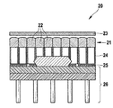
図9は、本発明によるデュアルモダリティイメージングシステムの一部とすることができる光イメージング検出器を示す。 FIG. 9 shows an optical imaging detector that can be part of a dual-modality imaging system according to the present invention.
この図は、検出器ブロック20の断面図を示している。本発明によるデュアルモダリティイメージングシステムの光イメージング検出器は、1つのそうした検出器ブロック20または複数の検出器ブロック20を備えることができる。検出器ブロック20は、2次元の格子の中で配置される複数のマイクロレンズ22を備えるマイクロレンズアレイ21を含む。マイクロレンズ22全ては、同一の幾何学的特性および同一の光学的特性を有することが好ましいが、適用例について必要であれば、これらの特性はマイクロレンズアレイ21の個々のマイクロレンズ22に関連して変更できる。マイクロレンズ22の直径は、適用例に必要とされる空間分解能特性に基づいて選択される。典型的には、レンズ直径0.48mmおよび1.0mmが2つの異なる適用例のために選択されている。
This figure shows a cross-sectional view of the
検出器ブロック20は、マイクロレンズアレイ21の前に置かれるフィルタ23をさらに備える。フィルタ23は、撮像対象(図示せず)に最も近い検出器ブロック20の部品である。マイクロレンズアレイ21は、撮像対象に対し径方向に延長してフィルタ23の背後に装着される。フィルタ23は、例えば検出器ブロック20が蛍光イメージングのために使用されるときにレーザの励起光の除去のために設けられる。フィルタ23は、生物ルミネセンスイメージングのためには必要とされない。
The
マイクロレンズアレイ21の反対側で、光コリメータ24は、マイクロレンズアレイ21の前に置かれる。このフォトレジストコリメータ24は、マイクロレンズアレイ21のマイクロレンズの配列およびピッチと同様の穴の配列およびピッチを有することが好ましい。コリメータ24は、マイクロレンズ22の個々の視野の間でクロストークを回避するために設けられる。径方向に延長したコリメータ24の厚さは、マイクロレンズアレイ21の面に向かい合う背面とマイクロレンズ22の仮想焦点面の間の空間に依存する。
On the opposite side of the
大きなフィールドの光検出器25は、コリメータ24の隣に装着される。光検出器25は、マイクロレンズアレイ21の焦点面に置かれる。この光検出器25は、CCDベースの検出器、APDアレイ、フォトダイオードアレイ、CMOSセンサおよび他の任意の位置敏感光検出器とすることができる。好ましくは、光検出器25は、その性能(感度、ノイズ特性、時間分解能など)の観点およびそのコストの観点で多くの利点を示すCMOSセンサである。光検出器25は、フィルタ23、マイクロレンズアレイ21および光コリメータ24を通過する入射光を電気信号に変換する。
A
マイクロレンズアレイ21のマイクロレンズ22は、あるピッチで離されており、このピッチは、取得される画像の中のモアレアーチファクトを回避するために、多数の光検出器25のピッチに等しくすべきである。典型的にはある実験装置では、レンズピッチ0.48mmに等しいレンズ直径であるマイクロレンズ22が使用される。用いられるCMOSセンサのピッチは、この1/10(0.048mm)となるように選択される。光検出器25は、個々のセンサ素子からなる2次元の格子からなる位置敏感センサである。
The
結像および検出のために使用される前述の検出器の全部品21、23、24および25の全体的な寸法は、等しいものにすべきである。すなわち、マイクロレンズアレイ21の大きさが視野1cm×1cmを描くように選択される場合、センサ25、コリメータ24およびフィルタ23の大きさも同様にすべきである。しかし、これは検出の目的だけに要求されるのではない。原理上は、検出器の部品21、23、および24は、交換可能であってよく、それによりイメージング特性の修正を可能にする。追加の電子機器の部品および信号変換要素26が必要である場合、示したCMOS設計と同じように、追加の電子機器の部品および信号変換要素26は検出器の視野の外側に(PETの視野からも外へ)置かれるべきである。
The overall dimensions of all the
図9の検出器ブロック20は、2次元の(すなわち平坦の)断層撮影法イメージングに使用可能であり、あるいはある形で組み立てられるまたは回転される場合には十分に3次元の断層撮影法イメージングに使用可能である。ほとんどの適用シナリオでは、検出器ブロック20は、撮像対象とは接触しておらず、所定の距離に置かれるが、検出器ブロック20のマイクロレンズアレイ検出器の表面は、撮像対象またはその部分に対して直角に向けられている。そうした検出器ブロック20の感光の大きさ(sensitive size)は、(技術的な処理によって制約されているが)任意に選択できるが、撮像対象またはその部分の大きさによって決定されるべきである。典型的には、検出器ブロックの大きさは、(軸方向に延在している)ネズミ全体が図によって撮像できるように(軸と垂直な方向に)5mm×(軸方向に)70mmであるように選択される。別の具体的な適用例では、ある検出器の大きさは、(軸と垂直な方向に)25mm×(軸方向に)70mmで選択される。この場合、検出器の視野は、ネズミ全体を覆う。
The
図10は、複数の光検出器がリング構造に配置される位置敏感光検出器を備えており、リング構造はガンマ線検出器アレイのリング形の内に配置される、本発明によるデュアルモダリティイメージングシステムの斜視図を示す。 FIG. 10 shows a dual-modality imaging system according to the present invention comprising a position sensitive photodetector in which a plurality of photodetectors are arranged in a ring structure, the ring structure being arranged in a ring shape of a gamma ray detector array. FIG.
図11は、図10によるデュアルモダリティイメージングシステムの軸と垂直な方向の図を示す。 FIG. 11 shows a view in a direction perpendicular to the axis of the dual-modality imaging system according to FIG.
図12は、図10によるデュアルモダリティイメージングシステムの軸方向の図を示す。 FIG. 12 shows an axial view of the dual modality imaging system according to FIG.
図10、図11および図12では、図9による複数の光イメージング検出器ブロック20は、撮像対象27、この場合はネズミのファントムを囲むリング構造に配置される。このデュアルモダリティイメージングシステムは、これらの光イメージング検出器ブロック20の組合せによって構成されており、PETシステムは、撮像対象27を囲むリング形7に配置された複数のガンマ線検出器アレイ6を備えている。ガンマ線検出器アレイ6は、高エネルギー(511keV)の同位体光子を検出することができる。ガンマ線検出器アレイ6は、内部の円筒を形成する光検出器20に対し径方向に延長して離されている。両方のサブシステムは、共通のガントリ上に装着される。(フィルタ、マイクロレンズアレイ、光検出器および光コリメータを備える検出器ブロック20を備える)光検出システムはPETサブシステムの視野内で配置されるが、高エネルギーの光子は組合せ材料の中で減衰および散乱によって最小限に影響を及ぼされるだけであるので、光システムは同位体光子の影響を受けず、PETシステムは光検出器ブロック20によって(ほとんど)影響されない。光マイクロレンズ系は、光学的光子を「ストリッピングアウェイ」しており、同位体光子に影響がない。光/PET検出器ブロックの大きさは任意に選択可能であるが、撮像対象27の大きさまたは撮像対象27の一部分によって決定されるべきである。典型的には、光検出器の大きさは、(軸方向に延在している)ネズミ全体がただ1回の手続きで撮像できるように10個の円筒形に組み立てられた検出器ブロック20(円筒の直径は32mmに等しい)全てについて(軸と垂直な方向に)10mm×(軸方向に)70mmであるように選択される。マイクロレンズ直径は、例えば0.480mmとなるように選択可能である。図10、図11および図12に例示されるPETシステムでは、リング直径70mmであるリング28ごとに円筒形に割り当てられる20個のガンマ線検出器アレイ6がある。ガンマ線検出器アレイ6それぞれは、10mm×10mmの感光区域を有する。互いに取付けられた6つのリング28がある。レーザ29は、PETリング28の背後で径方向に延長して置かれる。レーザ29は、蛍光イメージングでプローブ励起のために使用される。光検出器構成およびPET検出器は、レーザ光ビーム30が個々のブロックの間隙31を通って送られることができるように配置される。レーザ29それぞれは、好ましくはその回転軸に沿って平行移動方向32に平行移動可能であり、システム全体(光検出器20、PET検出器6およびレーザ29)は回転可能である。これにより、特に光システムの任意のプローブ励起および向上した空間サンプリングが可能となる。
In FIGS. 10, 11 and 12, the plurality of optical imaging detector blocks 20 according to FIG. 9 are arranged in a ring structure surrounding an
1 第1のCCDカメラ
2 第2のCCDカメラ
3 第1の平坦なガンマ線検出器アレイ
4 第2の平坦なガンマ線検出器アレイ
5 (「Derenzo」型ファントムとして示される)撮像対象
6 ガンマ線検出器アレイ
7 リング形
8 CCDカメラ
9 垂直軸
10 マイクロレンズアレイ
11 リング構造
12 光ファイバ
13 空間
14 電気接続
15 ファイバ束
16 光コリメータ
17 多穴プレート
18 マイクロレンズ
19 穴
20 検出器ブロック
21 マイクロレンズアレイ
22 マイクロレンズ
23 フィルタ
24 光コリメータ
25 光検出器
26 電子機器の部品および信号変換要素
27 撮像対象
28 リング
29 レーザ
30 レーザ光ビーム
31 間隙
32 平行移動方向
DESCRIPTION OF SYMBOLS 1
Claims (26)
Reconstructing a PET image and an optical image with the acquired PET imaging data and the optical imaging data, and displaying at least one of the PET image, the optical image, or the fused PET / optical image on a display device The method of claim 25, comprising the step of:
Applications Claiming Priority (3)
| Application Number | Priority Date | Filing Date | Title |
|---|---|---|---|
| EP05008552.1 | 2005-04-19 | ||
| EP05008552.1A EP1715361B1 (en) | 2005-04-19 | 2005-04-19 | Dual-modality imaging using a PET scanner and an optical detector |
| PCT/EP2006/061474 WO2006111485A2 (en) | 2005-04-19 | 2006-04-10 | Dual-modality imaging using a pet scanner and an optical detector |
Publications (2)
| Publication Number | Publication Date |
|---|---|
| JP2008538312A JP2008538312A (en) | 2008-10-23 |
| JP5319276B2 true JP5319276B2 (en) | 2013-10-16 |
Family
ID=35355294
Family Applications (3)
| Application Number | Title | Priority Date | Filing Date |
|---|---|---|---|
| JP2008507050A Pending JP2008537131A (en) | 2005-04-19 | 2006-04-10 | Optical imaging detector |
| JP2008507049A Expired - Fee Related JP5319276B2 (en) | 2005-04-19 | 2006-04-10 | Dual-modality imaging system and method |
| JP2012171278A Pending JP2012237759A (en) | 2005-04-19 | 2012-08-01 | Optical imaging detector |
Family Applications Before (1)
| Application Number | Title | Priority Date | Filing Date |
|---|---|---|---|
| JP2008507050A Pending JP2008537131A (en) | 2005-04-19 | 2006-04-10 | Optical imaging detector |
Family Applications After (1)
| Application Number | Title | Priority Date | Filing Date |
|---|---|---|---|
| JP2012171278A Pending JP2012237759A (en) | 2005-04-19 | 2012-08-01 | Optical imaging detector |
Country Status (5)
| Country | Link |
|---|---|
| US (2) | US7786443B2 (en) |
| EP (2) | EP1715361B1 (en) |
| JP (3) | JP2008537131A (en) |
| CA (3) | CA2615580C (en) |
| WO (2) | WO2006111486A1 (en) |
Families Citing this family (26)
| Publication number | Priority date | Publication date | Assignee | Title |
|---|---|---|---|---|
| EP1715361B1 (en) * | 2005-04-19 | 2015-02-25 | Deutsches Krebsforschungszentrum Stiftung des öffentlichen Rechts | Dual-modality imaging using a PET scanner and an optical detector |
| EP1898206A1 (en) | 2006-09-06 | 2008-03-12 | DKFZ Deutsches Krebsforschungszentrum | Dual-modality imaging |
| US7737407B2 (en) * | 2007-07-03 | 2010-06-15 | Siemens Medical Solutions Usa, Inc. | Method and apparatus for providing depth-of-interaction detection using positron emission tomography (PET) |
| WO2009006758A1 (en) * | 2007-07-10 | 2009-01-15 | Tsinghua University | Continuous and dynamical acquisition-type imaging system for small animal induced fluorescence molecule imaging |
| CN101778598B (en) | 2007-08-10 | 2013-03-27 | 皇家飞利浦电子股份有限公司 | Motion detection in medical systems |
| US8653464B2 (en) * | 2007-10-11 | 2014-02-18 | Deutsches Krebsforschungszentrum Stiftung Des Oeffentlichen Rechts | Combination of single photon emission computed tomography and optical imaging detector |
| US20090212224A1 (en) * | 2008-02-21 | 2009-08-27 | James Mark Long | Nuclear imaging scanner with event position-identifying accelerometers |
| US10048392B2 (en) | 2008-02-21 | 2018-08-14 | Siemens Medical Solutions Usa, Inc. | Nuclear imaging scanner with event position-identifying accelerometers |
| CN101485560B (en) * | 2008-11-17 | 2011-04-27 | 清华大学 | Non-contact stationary type fluorescent molecular tomography method and device |
| US8395128B2 (en) * | 2009-02-16 | 2013-03-12 | Shimadzu Corporation | Radiation tomography apparatus |
| CN102598088A (en) * | 2009-11-11 | 2012-07-18 | 艾克提维尤斯有限公司 | Systems & methods for planning and performing percutaneous needle procedures |
| JP6373005B2 (en) | 2010-11-11 | 2018-08-15 | ザ トラスティーズ オブ コロンビア ユニバーシティ イン ザ シティ オブ ニューヨーク | Dynamic optical tomography imaging apparatus, method and system |
| CN102525521A (en) * | 2010-12-13 | 2012-07-04 | 北京大基康明医疗设备有限公司 | Flashing layered phototropic vision |
| ES2793373T3 (en) * | 2010-12-30 | 2020-11-13 | Alltec Angewandte Laserlicht Tech Gesellschaft Mit Beschraenkter Haftung | Sensor apparatus |
| DE102011006435B4 (en) * | 2011-03-30 | 2020-08-27 | Siemens Healthcare Gmbh | Image recording device for the simultaneous recording of magnetic resonance image data and nuclear medicine image data |
| DE112011105202T5 (en) | 2011-05-30 | 2014-01-30 | Hamamatsu Photonics K.K. | Inclined PET device and PET combination device |
| WO2013003469A2 (en) * | 2011-06-27 | 2013-01-03 | Bioscan, Inc. | Method and apparatus for automated indexing of pluralities of filter arrays |
| JP5970785B2 (en) * | 2011-11-16 | 2016-08-17 | ソニー株式会社 | Biological measuring device, biological measuring method, program, and recording medium |
| US9071763B1 (en) | 2012-09-26 | 2015-06-30 | Google Inc. | Uniform illumination image capture |
| US20160141318A1 (en) * | 2013-06-28 | 2016-05-19 | Teledyne Dalsa, Inc. | Method and system for assembly of radiological imaging sensor |
| WO2016168996A1 (en) * | 2015-04-22 | 2016-10-27 | Shenzhen Genorivision Technology Co., Ltd. | A biosensor |
| US9696439B2 (en) | 2015-08-10 | 2017-07-04 | Shanghai United Imaging Healthcare Co., Ltd. | Apparatus and method for PET detector |
| EP3660542A1 (en) * | 2018-11-29 | 2020-06-03 | Koninklijke Philips N.V. | Hybrid x-ray and optical detector |
| DE102019219306A1 (en) | 2019-12-11 | 2021-06-17 | Siemens Healthcare Gmbh | Hybrid medical device |
| EP3855239A1 (en) * | 2020-01-21 | 2021-07-28 | Iray Technology Company Limited | Radiation image detector and manufacture method thereof |
| CN111134705B (en) | 2020-01-21 | 2023-10-13 | 上海奕瑞光电子科技股份有限公司 | Radiation image detector and manufacturing method thereof |
Family Cites Families (29)
| Publication number | Priority date | Publication date | Assignee | Title |
|---|---|---|---|---|
| US3927318A (en) * | 1974-05-06 | 1975-12-16 | Albert Macovski | Cross-sectional fluorescent imaging system |
| US4559597A (en) * | 1982-07-07 | 1985-12-17 | Clayton Foundation For Research | Three-dimensional time-of-flight positron emission camera system |
| JPH03157602A (en) * | 1989-11-16 | 1991-07-05 | Nippon Sheet Glass Co Ltd | Image transmission element and production of light shielding plate used for this element |
| JP3217107B2 (en) | 1992-02-14 | 2001-10-09 | 科学技術振興事業団 | Fluorescence tomogram measurement system |
| JPH05261108A (en) * | 1992-03-19 | 1993-10-12 | Hitachi Ltd | Optically measuring system for living body |
| DE4318823C2 (en) * | 1993-06-07 | 2002-08-29 | Zeiss Carl | Device for scanning optical tissue examination |
| US5656807A (en) * | 1995-09-22 | 1997-08-12 | Packard; Lyle E. | 360 degrees surround photon detector/electron multiplier with cylindrical photocathode defining an internal detection chamber |
| US5825031A (en) | 1996-10-11 | 1998-10-20 | Board Of Regents The University Of Texas System | Tomographic pet camera with adjustable diameter detector ring |
| US5923481A (en) * | 1996-11-27 | 1999-07-13 | The Regents Of The University Of California | Microlens frames for laser diode arrays |
| JP2000180365A (en) | 1998-12-15 | 2000-06-30 | Fuji Photo Film Co Ltd | Image data reading apparatus |
| US6307243B1 (en) * | 1999-07-19 | 2001-10-23 | Micron Technology, Inc. | Microlens array with improved fill factor |
| JP3551860B2 (en) * | 1999-10-05 | 2004-08-11 | 株式会社日立製作所 | DNA testing method and DNA testing device |
| US20020175267A1 (en) | 2000-03-15 | 2002-11-28 | Watson Robert Malcolm | Direct imaging system for emission microscopy |
| EP1284654A4 (en) | 2000-05-09 | 2004-03-24 | Imaging Diagnostic Systems Inc | Medical optical imaging scanner using multiple wavelength simultaneous data acquisition for breast imaging |
| AU2001293592A1 (en) * | 2000-10-06 | 2002-04-15 | Peter R. Herman | Multi-spectral fluorescence imaging and spectroscopy device |
| JP3672085B2 (en) * | 2000-10-11 | 2005-07-13 | シャープ株式会社 | Solid-state imaging device and manufacturing method thereof |
| US7113217B2 (en) | 2001-07-13 | 2006-09-26 | Xenogen Corporation | Multi-view imaging apparatus |
| DE10202050A1 (en) * | 2002-01-18 | 2003-07-31 | Siemens Ag | Imaging of live small animals using luminescence techniques for biological, medical and pharmaceutical research, whereby LEDs are used as a cost effective and low-power light source that provides sufficient excitation light energy |
| US7238943B2 (en) * | 2002-02-01 | 2007-07-03 | Board Of Regents, The University Of Texas System | Asymmetrically placed cross-coupled scintillation crystals |
| DE10225932B4 (en) * | 2002-06-11 | 2007-01-11 | Deutsches Krebsforschungszentrum (Dkfz) | Imaging method and apparatus for carrying it out |
| JP2004191251A (en) * | 2002-12-12 | 2004-07-08 | Olympus Corp | Fluorescence spectroscopic analyzer |
| WO2004081865A2 (en) * | 2003-03-10 | 2004-09-23 | University Of Iowa Research Foundation | Systems and methods for bioliminescent computed tomographic reconstruction |
| US7291841B2 (en) * | 2003-06-16 | 2007-11-06 | Robert Sigurd Nelson | Device and system for enhanced SPECT, PET, and Compton scatter imaging in nuclear medicine |
| JP2005019858A (en) * | 2003-06-27 | 2005-01-20 | Toppan Printing Co Ltd | Two-dimension image converting element |
| US7190991B2 (en) * | 2003-07-01 | 2007-03-13 | Xenogen Corporation | Multi-mode internal imaging |
| US6987619B2 (en) * | 2004-03-31 | 2006-01-17 | General Electric Company | Lens array package and fabrication method |
| JP2006058044A (en) * | 2004-08-18 | 2006-03-02 | Yokogawa Electric Corp | Cartridge for biochip and biochip reading apparatus |
| US6987274B1 (en) * | 2004-08-31 | 2006-01-17 | Palo Alto Research Center Incorporated | Light detection and imaging system and method including an array of sensors |
| EP1715361B1 (en) * | 2005-04-19 | 2015-02-25 | Deutsches Krebsforschungszentrum Stiftung des öffentlichen Rechts | Dual-modality imaging using a PET scanner and an optical detector |
-
2005
- 2005-04-19 EP EP05008552.1A patent/EP1715361B1/en not_active Not-in-force
-
2006
- 2006-04-10 CA CA2615580A patent/CA2615580C/en active Active
- 2006-04-10 CA CA002651257A patent/CA2651257A1/en active Pending
- 2006-04-10 US US11/918,790 patent/US7786443B2/en active Active
- 2006-04-10 EP EP06743272.4A patent/EP1875210B1/en active Active
- 2006-04-10 JP JP2008507050A patent/JP2008537131A/en active Pending
- 2006-04-10 JP JP2008507049A patent/JP5319276B2/en not_active Expired - Fee Related
- 2006-04-10 CA CA2665980A patent/CA2665980C/en not_active Expired - Fee Related
- 2006-04-10 US US11/918,857 patent/US8227754B2/en active Active
- 2006-04-10 WO PCT/EP2006/061475 patent/WO2006111486A1/en not_active Application Discontinuation
- 2006-04-10 WO PCT/EP2006/061474 patent/WO2006111485A2/en not_active Application Discontinuation
-
2012
- 2012-08-01 JP JP2012171278A patent/JP2012237759A/en active Pending
Also Published As
| Publication number | Publication date |
|---|---|
| EP1715361B1 (en) | 2015-02-25 |
| EP1715361A1 (en) | 2006-10-25 |
| JP2008537131A (en) | 2008-09-11 |
| US20090039268A1 (en) | 2009-02-12 |
| EP1875210A1 (en) | 2008-01-09 |
| US7786443B2 (en) | 2010-08-31 |
| US20090032714A1 (en) | 2009-02-05 |
| US8227754B2 (en) | 2012-07-24 |
| CA2615580C (en) | 2014-06-03 |
| EP1875210B1 (en) | 2017-11-01 |
| CA2665980A1 (en) | 2006-10-26 |
| CA2651257A1 (en) | 2006-10-26 |
| CA2665980C (en) | 2015-06-02 |
| JP2012237759A (en) | 2012-12-06 |
| CA2615580A1 (en) | 2006-10-26 |
| JP2008538312A (en) | 2008-10-23 |
| WO2006111485A3 (en) | 2006-12-28 |
| WO2006111485A2 (en) | 2006-10-26 |
| WO2006111486A1 (en) | 2006-10-26 |
Similar Documents
| Publication | Publication Date | Title |
|---|---|---|
| JP5319276B2 (en) | Dual-modality imaging system and method | |
| EP1916543A1 (en) | Triple-modality imaging system | |
| EP2062032B1 (en) | Dual-modality imaging | |
| EP2201408B1 (en) | Combination of single photon emission computed tomography and optical imaging detector | |
| US20090302228A1 (en) | Device for quantification of radioisotope concentrations in a micro-fluidic platform | |
| JP4471834B2 (en) | Imaging method and apparatus for performing the method | |
| Massari et al. | Super Spatial Resolution (SSR) method for small animal SPECT imaging: A Monte Carlo study | |
| MacDonald et al. | The PET/X dedicated breast-PET scanner for optimizing cancer therapy | |
| Peter et al. | PET-MOT-A novel concept for simultaneous positron and optical tomography in small animals | |
| Peter | Dual-Modality Preclinical PET-OI Concepts and Instrumentation | |
| Shao et al. | Design studies of a high-performance onboard positron emission tomography for integrated small animal PET/CT/RT radiation research systems | |
| Peter et al. | Instrumentation setup for simultaneous measurement of optical and positron labeled probes in mice | |
| CN112932513A (en) | Medical imaging system |
Legal Events
| Date | Code | Title | Description |
|---|---|---|---|
| A621 | Written request for application examination |
Free format text: JAPANESE INTERMEDIATE CODE: A621 Effective date: 20090311 |
|
| A131 | Notification of reasons for refusal |
Free format text: JAPANESE INTERMEDIATE CODE: A131 Effective date: 20110705 |
|
| A131 | Notification of reasons for refusal |
Free format text: JAPANESE INTERMEDIATE CODE: A131 Effective date: 20120228 |
|
| A521 | Request for written amendment filed |
Free format text: JAPANESE INTERMEDIATE CODE: A523 Effective date: 20120525 |
|
| A131 | Notification of reasons for refusal |
Free format text: JAPANESE INTERMEDIATE CODE: A131 Effective date: 20130312 |
|
| A521 | Request for written amendment filed |
Free format text: JAPANESE INTERMEDIATE CODE: A523 Effective date: 20130528 |
|
| TRDD | Decision of grant or rejection written | ||
| A01 | Written decision to grant a patent or to grant a registration (utility model) |
Free format text: JAPANESE INTERMEDIATE CODE: A01 Effective date: 20130618 |
|
| A61 | First payment of annual fees (during grant procedure) |
Free format text: JAPANESE INTERMEDIATE CODE: A61 Effective date: 20130711 |
|
| R150 | Certificate of patent or registration of utility model |
Ref document number: 5319276 Country of ref document: JP Free format text: JAPANESE INTERMEDIATE CODE: R150 Free format text: JAPANESE INTERMEDIATE CODE: R150 |
|
| R250 | Receipt of annual fees |
Free format text: JAPANESE INTERMEDIATE CODE: R250 |
|
| R250 | Receipt of annual fees |
Free format text: JAPANESE INTERMEDIATE CODE: R250 |
|
| R250 | Receipt of annual fees |
Free format text: JAPANESE INTERMEDIATE CODE: R250 |
|
| R250 | Receipt of annual fees |
Free format text: JAPANESE INTERMEDIATE CODE: R250 |
|
| R250 | Receipt of annual fees |
Free format text: JAPANESE INTERMEDIATE CODE: R250 |
|
| R250 | Receipt of annual fees |
Free format text: JAPANESE INTERMEDIATE CODE: R250 |
|
| LAPS | Cancellation because of no payment of annual fees |